tivaware™ usb library
TRANSCRIPT

Copyright © 2008-2013Texas Instruments Incorporated
SW-TM4C-USBL-UG-1.1
USER’S GUIDE
TivaWare™ USB Library

CopyrightCopyright © 2008-2013 Texas Instruments Incorporated. All rights reserved. Tiva and TivaWare are trademarks of Texas Instruments Instruments. ARMand Thumb are registered trademarks and Cortex is a trademark of ARM Limited. Other names and brands may be claimed as the property of others.
Please be aware that an important notice concerning availability, standard warranty, and use in critical applications of Texas Instruments semicon-ductor products and disclaimers thereto appears at the end of this document.
Texas Instruments108 Wild Basin, Suite 350Austin, TX 78746www.ti.com/tiva-c
Revision InformationThis is version 1.1 of this document, last updated on July 02, 2013.
2 July 02, 2013
Table of Contents
Table of ContentsCopyright . . . . . . . . . . . . . . . . . . . . . . . . . . . . . . . . . . . . . . . . . . . . . . . . . . . . . 2
Revision Information . . . . . . . . . . . . . . . . . . . . . . . . . . . . . . . . . . . . . . . . . . . . . . . 2
1 Introduction . . . . . . . . . . . . . . . . . . . . . . . . . . . . . . . . . . . . . . . . . . . . . . . . . 51.1 Operating Modes . . . . . . . . . . . . . . . . . . . . . . . . . . . . . . . . . . . . . . . . . . . . . . 51.2 File Structure and Tools . . . . . . . . . . . . . . . . . . . . . . . . . . . . . . . . . . . . . . . . . . . 6
2 Device Functions . . . . . . . . . . . . . . . . . . . . . . . . . . . . . . . . . . . . . . . . . . . . . . 72.1 Introduction . . . . . . . . . . . . . . . . . . . . . . . . . . . . . . . . . . . . . . . . . . . . . . . . . . 72.2 API choices for USB devices . . . . . . . . . . . . . . . . . . . . . . . . . . . . . . . . . . . . . . . . 82.3 Audio Device Class Driver . . . . . . . . . . . . . . . . . . . . . . . . . . . . . . . . . . . . . . . . . 112.4 Audio Device Class Driver Definitions . . . . . . . . . . . . . . . . . . . . . . . . . . . . . . . . . . . 172.5 Bulk Device Class Driver . . . . . . . . . . . . . . . . . . . . . . . . . . . . . . . . . . . . . . . . . . 232.6 Bulk Device Class Driver Definitions . . . . . . . . . . . . . . . . . . . . . . . . . . . . . . . . . . . . 332.7 CDC Device Class Driver . . . . . . . . . . . . . . . . . . . . . . . . . . . . . . . . . . . . . . . . . . 412.8 CDC Device Class Driver Definitions . . . . . . . . . . . . . . . . . . . . . . . . . . . . . . . . . . . . 502.9 Composite Device Class Driver . . . . . . . . . . . . . . . . . . . . . . . . . . . . . . . . . . . . . . . 602.10 Composite Device Class Driver Definitions . . . . . . . . . . . . . . . . . . . . . . . . . . . . . . . . 662.11 Device Firmware Upgrade Device Class Driver . . . . . . . . . . . . . . . . . . . . . . . . . . . . . . 682.12 Device Firmware Upgrade Device Class Driver Definitions . . . . . . . . . . . . . . . . . . . . . . . 722.13 HID Device Class Driver . . . . . . . . . . . . . . . . . . . . . . . . . . . . . . . . . . . . . . . . . . 752.14 HID Device Class Driver Definitions . . . . . . . . . . . . . . . . . . . . . . . . . . . . . . . . . . . . 852.15 HID Mouse Device Class API . . . . . . . . . . . . . . . . . . . . . . . . . . . . . . . . . . . . . . . . 1102.16 HID Mouse Device Class API Definitions . . . . . . . . . . . . . . . . . . . . . . . . . . . . . . . . . 1132.17 HID Keyboard Device Class API . . . . . . . . . . . . . . . . . . . . . . . . . . . . . . . . . . . . . . 1192.18 HID Keyboard Device Class API Definitions . . . . . . . . . . . . . . . . . . . . . . . . . . . . . . . . 1222.19 Mass Storage Device Class API . . . . . . . . . . . . . . . . . . . . . . . . . . . . . . . . . . . . . . 1292.20 Mass Storage Device Class API Definitions . . . . . . . . . . . . . . . . . . . . . . . . . . . . . . . . 1352.21 Using the USB Device API . . . . . . . . . . . . . . . . . . . . . . . . . . . . . . . . . . . . . . . . . 1402.22 USB Device API Definitions . . . . . . . . . . . . . . . . . . . . . . . . . . . . . . . . . . . . . . . . . 151
3 Host Functions . . . . . . . . . . . . . . . . . . . . . . . . . . . . . . . . . . . . . . . . . . . . . . . 1633.1 Introduction . . . . . . . . . . . . . . . . . . . . . . . . . . . . . . . . . . . . . . . . . . . . . . . . . . 1633.2 Host Controller Driver . . . . . . . . . . . . . . . . . . . . . . . . . . . . . . . . . . . . . . . . . . . . 1653.3 Host Controller Driver Definitions . . . . . . . . . . . . . . . . . . . . . . . . . . . . . . . . . . . . . . 1673.4 Host Class Driver . . . . . . . . . . . . . . . . . . . . . . . . . . . . . . . . . . . . . . . . . . . . . . 1843.5 Host Class Driver Definitions . . . . . . . . . . . . . . . . . . . . . . . . . . . . . . . . . . . . . . . . 1953.6 Host Device Interface . . . . . . . . . . . . . . . . . . . . . . . . . . . . . . . . . . . . . . . . . . . . 2193.7 Host Device Interface Definitions . . . . . . . . . . . . . . . . . . . . . . . . . . . . . . . . . . . . . . 2213.8 Host Programming Examples . . . . . . . . . . . . . . . . . . . . . . . . . . . . . . . . . . . . . . . . 226
4 OTG Functions . . . . . . . . . . . . . . . . . . . . . . . . . . . . . . . . . . . . . . . . . . . . . . . 2354.1 Introduction . . . . . . . . . . . . . . . . . . . . . . . . . . . . . . . . . . . . . . . . . . . . . . . . . . 2354.2 OTG Controller Driver . . . . . . . . . . . . . . . . . . . . . . . . . . . . . . . . . . . . . . . . . . . . 2354.3 OTG Controller Definitions . . . . . . . . . . . . . . . . . . . . . . . . . . . . . . . . . . . . . . . . . 2374.4 OTG Programming Examples . . . . . . . . . . . . . . . . . . . . . . . . . . . . . . . . . . . . . . . . 240
5 General Purpose Functions . . . . . . . . . . . . . . . . . . . . . . . . . . . . . . . . . . . . . . . . 2435.1 Introduction . . . . . . . . . . . . . . . . . . . . . . . . . . . . . . . . . . . . . . . . . . . . . . . . . . 2435.2 Function Definitions . . . . . . . . . . . . . . . . . . . . . . . . . . . . . . . . . . . . . . . . . . . . . 2445.3 USB Events . . . . . . . . . . . . . . . . . . . . . . . . . . . . . . . . . . . . . . . . . . . . . . . . . 2535.4 USB Chapter 9 Definitions . . . . . . . . . . . . . . . . . . . . . . . . . . . . . . . . . . . . . . . . . 259
July 02, 2013 3

Table of Contents
5.5 USB Buffer and Ring Buffer APIs . . . . . . . . . . . . . . . . . . . . . . . . . . . . . . . . . . . . . . 2675.6 Internal USB DMA functions . . . . . . . . . . . . . . . . . . . . . . . . . . . . . . . . . . . . . . . . 283
IMPORTANT NOTICE . . . . . . . . . . . . . . . . . . . . . . . . . . . . . . . . . . . . . . . . . . . . . . . 292
4 July 02, 2013

Introduction
1 IntroductionThe Texas Instruments® USB Library is a set of data types and functions for creating USB device,host or On-The-Go (OTG) applications. The contents of the USB library and its associated headerfiles fall into four main groups: general purpose functions, device mode specific functions, hostmode specific functions, and mode detection and control functions.
The set of general purpose functions are those that are be used in device, host, and dual modeapplications. These include functions to parse USB descriptors and configure features of the USBlibrary. The device specific functions provide the class-independent features required by all USBdevice applications such as host connection signaling and responding to standard descriptor re-quests. The USB library also contains a set of modules that handle the class specific requests fromthe USB host as well as a layer to interact with an application. The USB library provides a set oflower level class-independent host functions required by all USB host applications such as devicedetection and enumeration, and endpoint management. This lower layer remains mostly invisibleto the application, but can be exposed to the application via class specific USB host modules. Likethe device mode layer, the host mode class specific modules provide an interface to allow the lowerlevel USB library code to communicate directly over the USB bus and also has a higher level inter-face that interacts with the application. The USB library also provides functions to configure howthe USB controller handles switching between host and device mode operation. The modes andthe functions that control them are described in the next section.
1.1 Operating Modes
There are five modes that the USB Library can function in and they are set by application. Therun time operating mode of the USB controller is set by the way the USB controller is configured todetect the USB connection to another device. This mode detection can be automatic by using fullOTG operation, manual by using dual mode operation, or fixed to either host or device mode. In allcases these modes control how the USB controller interacts with the USB VBUS and USB ID pins.
When an application only needs to run in USB host mode it can choose how the device powersVBUS, the detection of over current, the automatic monitoring of VBUS. These are controlled atinitialization time by calls to USBStackModeSet() with on of the eUSBMode∗ values. If the appli-cation has no need to monitor VBUS it can choose to use the eUSBModeForceHost option. Thisstill provides the ability to control VBUS power and the over current detection but does not allow formonitoring VBUS. When the application does require that the controller be able to monitor VBUS ituses the eUSBModeHost setting. This setting also requires that the ID pin be externally tied lowas it does not fully disable the OTG mode of operation for mode detection.
If an application only needs to run in device mode there are two options to control how device modeis entered. The USBStackModeSet() function is still used to control the mode but and if the appli-cation needs to use the VBUS and ID for other purposes, it can use the eUSBModeForceDeviceto ignore these pins. The impact of this is that the application is not informed of USB discon-nection events because it can no longer monitor VBUS. This is only a problem for self poweredapplications and can be handled by monitoring VBUS on a separate pin. If the application needs toreceive disconnect events it must connect the VBUS pin to the USB connector and leave the ID pinunconnected.
Some application also need to run as either host or device and the USB library provides two meth-ods to handle switching modes on the fly. The first is to use the normal USB OTG signaling tocontrol mode switching which requires both the ID and VBUS pins to be connected to the USB
July 02, 2013 5
Introduction
connector. This is designed to work with a single USB AB connector. See the USB OTG section ofthis document for further details on operating in OTG mode. Another method of switching operatingmode is to allow the application to choose the operating mode of the USB controller manually. Thisis more useful when the application is using a host and a device connector and can detect when itneeds to manually switch the USB operating mode. The APIs and further description is in the dualmode section of this document.
1.2 File Structure and Tools
The following tool chains are supported:
Keil™ RealView® Microcontroller Development Kit
CodeSourcery Sourcery G++
IAR Embedded Workbench®
Texas Instruments Code Composer Studio™
Directory Structure Overview
The following is an overview of the organization of the USB library source code, along with refer-ences to where each portion is described in detail.
usblib The main directory under DriverLib contains the Makefile used to build thelibrary and also source files and headers for functions and data types whichare of general use to device and host applications. The contents of thisdirectory are described in chapter 5.
usblib/device/ This directory contains source code and header files relating to operationas a USB device. The contents of this directory are described in chapter 2.
usblib/host/ This directory contains source code and header files relating to operationas a USB host. The contents of this directory are described in chapter 3.
6 July 02, 2013
Device Functions
2 Device FunctionsIntroduction . . . . . . . . . . . . . . . . . . . . . . . . . . . . . . . . . . . . . . . . . . . . . . . . . . . . . . . . . . . . . . . . . . . . . . . . . . . . . . . . . . . . . . . . . . . . . . . 7API choices for USB devices . . . . . . . . . . . . . . . . . . . . . . . . . . . . . . . . . . . . . . . . . . . . . . . . . . . . . . . . . . . . . . . . . . . . . . . . . . . . . . 8Audio Device Class Driver . . . . . . . . . . . . . . . . . . . . . . . . . . . . . . . . . . . . . . . . . . . . . . . . . . . . . . . . . . . . . . . . . . . . . . . . . . . . . . . .11Audio Device Class Driver Definitions . . . . . . . . . . . . . . . . . . . . . . . . . . . . . . . . . . . . . . . . . . . . . . . . . . . . . . . . . . . . . . . . . . . . 17Bulk Device Class Driver . . . . . . . . . . . . . . . . . . . . . . . . . . . . . . . . . . . . . . . . . . . . . . . . . . . . . . . . . . . . . . . . . . . . . . . . . . . . . . . . . 23Bulk Device Class Driver Definitions . . . . . . . . . . . . . . . . . . . . . . . . . . . . . . . . . . . . . . . . . . . . . . . . . . . . . . . . . . . . . . . . . . . . . .33CDC Device Class Driver . . . . . . . . . . . . . . . . . . . . . . . . . . . . . . . . . . . . . . . . . . . . . . . . . . . . . . . . . . . . . . . . . . . . . . . . . . . . . . . . 41CDC Device Class Driver Definitions . . . . . . . . . . . . . . . . . . . . . . . . . . . . . . . . . . . . . . . . . . . . . . . . . . . . . . . . . . . . . . . . . . . . . 50Composite Device Class Driver . . . . . . . . . . . . . . . . . . . . . . . . . . . . . . . . . . . . . . . . . . . . . . . . . . . . . . . . . . . . . . . . . . . . . . . . . . 60Composite Device Class Driver Definitions . . . . . . . . . . . . . . . . . . . . . . . . . . . . . . . . . . . . . . . . . . . . . . . . . . . . . . . . . . . . . . . 66Device Firmware Upgrade Device Class Driver . . . . . . . . . . . . . . . . . . . . . . . . . . . . . . . . . . . . . . . . . . . . . . . . . . . . . . . . . . . 68Device Firmware Upgrade Device Class Driver Definitions . . . . . . . . . . . . . . . . . . . . . . . . . . . . . . . . . . . . . . . . . . . . . . . . 72HID Device Class Driver . . . . . . . . . . . . . . . . . . . . . . . . . . . . . . . . . . . . . . . . . . . . . . . . . . . . . . . . . . . . . . . . . . . . . . . . . . . . . . . . . 75HID Device Class Driver Definitions . . . . . . . . . . . . . . . . . . . . . . . . . . . . . . . . . . . . . . . . . . . . . . . . . . . . . . . . . . . . . . . . . . . . . . 85HID Mouse Device Class API . . . . . . . . . . . . . . . . . . . . . . . . . . . . . . . . . . . . . . . . . . . . . . . . . . . . . . . . . . . . . . . . . . . . . . . . . . . 110HID Mouse Device Class API Definitions . . . . . . . . . . . . . . . . . . . . . . . . . . . . . . . . . . . . . . . . . . . . . . . . . . . . . . . . . . . . . . . . 113HID Keyboard Device Class API . . . . . . . . . . . . . . . . . . . . . . . . . . . . . . . . . . . . . . . . . . . . . . . . . . . . . . . . . . . . . . . . . . . . . . . . 119HID Keyboard Device Class API Definitions . . . . . . . . . . . . . . . . . . . . . . . . . . . . . . . . . . . . . . . . . . . . . . . . . . . . . . . . . . . . . 122Mass Storage Device Class API . . . . . . . . . . . . . . . . . . . . . . . . . . . . . . . . . . . . . . . . . . . . . . . . . . . . . . . . . . . . . . . . . . . . . . . . 129Mass Storage Device Class API Definitions . . . . . . . . . . . . . . . . . . . . . . . . . . . . . . . . . . . . . . . . . . . . . . . . . . . . . . . . . . . . . 135Using the USB Device API . . . . . . . . . . . . . . . . . . . . . . . . . . . . . . . . . . . . . . . . . . . . . . . . . . . . . . . . . . . . . . . . . . . . . . . . . . . . . . 140Device Function Definitions . . . . . . . . . . . . . . . . . . . . . . . . . . . . . . . . . . . . . . . . . . . . . . . . . . . . . . . . . . . . . . . . . . . . . . . . . . . . . 151
2.1 Introduction
This chapter describes the various API layers within the USB library that offer support for applica-tions wishing to present themselves as USB devices. Several programming interfaces are providedranging from the thinnest layer which merely abstracts the underlying USB controller hardware tohigh level interfaces offering simple APIs supporting specific devices.
Source Code Overview
Source code and headers for the device specific USB functions can be found in the device directoryof the USB library tree, typically DriverLib/usblib/device.
usbdevice.h The header file containing device mode function prototypes and data typesoffered by the library. This file is the main header file defining the USB DeviceAPI.
usbdbulk.h The header file defining the USB generic bulk device class driver API.
usbdcdc.h The header file defining the USB Communication Device Class (CDC) deviceclass driver API.
July 02, 2013 7
Device Functions
usbdhid.h The header file defining the USB Human Interface Device (HID) device classdriver API.
usbdhidkeyb.h The header file defining the USB HID keyboard device class API.
usbdhidmouse.h The header file defining the USB HID keyboard device class API.
usbdenum.c The source code for the USB device enumeration functions offered by thelibrary.
usbdhandler.c The source code for the USB device interrupt handler.
usbdconfig.c The source code for the USB device configuration functions.
usbdcdesc.c The source code for functions used to parse configuration descriptors definedin terms of an array of sections (as used with the USB Device API).
usbdbulk.c The source code for the USB generic bulk device class driver.
usbdcdc.c The source code for the USB Communication Device Class (CDC) deviceclass driver.
usbdhid.c The source code for the USB Human Interface Device (HID) device classdriver.
usbdhidkeyb.c The source code for the USB HID keyboard device class.
usbdhidmouse.c The source code for the USB HID keyboard device class.
usbdevicepriv.h The private header file containing definitions shared between various sourcefiles in the device directory. Applications must not include this header.
2.2 API choices for USB devices
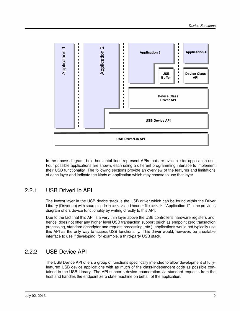
The USB library contains four API layers relevant to the development of USB device applications.Moving down the stack, each API layer offers greater flexibility to an application but this is balancedby the greater effort required to use the lower layers. The available programming interfaces, startingat the highest level and working downwards, are:
Device Class APIs
Device Class Driver APIs
The USB Device API
The USB DriverLib API
8 July 02, 2013
Device Functions
USB Device API
USB DriverLib API
USBBuffer
Device ClassDriver API
Device ClassAPI
App
licat
ion
1
App
licat
ion
2
Application 3 Application 4
In the above diagram, bold horizontal lines represent APIs that are available for application use.Four possible applications are shown, each using a different programming interface to implementtheir USB functionality. The following sections provide an overview of the features and limitationsof each layer and indicate the kinds of application which may choose to use that layer.
2.2.1 USB DriverLib API
The lowest layer in the USB device stack is the USB driver which can be found within the DriverLibrary (DriverLib) with source code in usb.c and header file usb.h. "Application 1" in the previousdiagram offers device functionality by writing directly to this API.
Due to the fact that this API is a very thin layer above the USB controller’s hardware registers and,hence, does not offer any higher level USB transaction support (such as endpoint zero transactionprocessing, standard descriptor and request processing, etc.), applications would not typically usethis API as the only way to access USB functionality. This driver would, however, be a suitableinterface to use if developing, for example, a third-party USB stack.
2.2.2 USB Device API
The USB Device API offers a group of functions specifically intended to allow development of fully-featured USB device applications with as much of the class-independent code as possible con-tained in the USB Library. The API supports device enumeration via standard requests from thehost and handles the endpoint zero state machine on behalf of the application.
July 02, 2013 9
Device Functions
An application using this interface provides the descriptors that it wishes to publish to the host duringinitialization and these provide the information that the USB Device API requires to configure thehardware. Asynchronous events relating to the USB device are notified to the application by meansof a collection of callback functions also provided to the USB Device API on initialization.
This API is used in the development of USB device class drivers and can also be used directlyby applications which want to provide USB functionality not supported by an existing class driver.Examples of such devices would be those requiring complex alternate interface settings.
The USB Device API can be thought of as a set of high level device extensions to the USB DriverLibAPI rather than a wrapper over it. When developing to the USB Device API, some calls to theunderlying USB DriverLib API are still necessary.
The header file for the USB Device API is device/usbdevice.h.
2.2.3 USB Device Class Driver APIs
Device Class Drivers offer high level USB function to applications wishing to offer particular USBfeatures without having to deal with most of the USB transaction handling and connection manage-ment that would otherwise be required. These drivers provide high level APIs for several commonly-used USB device classes with the following features.
Extremely easy to use. Device setup involves creating a set of static data structures andcalling a single initialization API.
Configurable VID/PID, power parameters and string table to allow easy customization of thedevice without the need to modify any library code.
Consistent interfaces. All device class drivers use similar APIs making it very straightforwardto move between them.
Minimal application overhead. The vast majority of USB handling is performed within the classdriver and lower layers leaving the application to deal only with reading and writing data.
May be used with optional USB buffer objects to further simplify data transmission and recep-tion. Using USB buffers, interaction with the device class driver can become as simple as aread/write API with no state machine required to ensure that data is transmitted or received atthe correct time.
Device Class Driver APIs completely wrap the underlying USB Device and USB Driver APIsso only a single API interface is used by the application.
Balancing these advantages, application developers should note the following restrictions that applywhen using the Device Class Driver APIs.
No calls may be made to any other USB layer while the device class driver API is in use.
Alternate configurations are not supported by the supplied device class drivers.
Device class drivers are currently provided to allow creation of a generic bulk device, a Communi-cation Device Class (virtual serial port) device and a Human Interface Device class device (mouse,keyboard, joystick, etc.). A special class driver for composite devices is also included. This acts asa wrapper allowing multiple device class drivers to be used in a single device. Detailed informationon each of these classes can be found later in this document.
10 July 02, 2013
Device Functions
2.2.4 USB Device Class APIs
In some cases, a standard device class may offer the possibility of creating a great number ofdifferent and varied devices using the same class and in these cases an additional API layer canbe provided to further specialize the device operation and simplify the interface to the application.
The Human Interface Device (HID) class is one such class. It is used to support a wide varietyof devices including keyboards, joysticks, mice and game controllers but the interface is specifiedin such a way that it could be used for a huge number of vendor-specific devices offering datagathering capability. As a result, the HID device class driver is extremely general to allow supportfor as wide a range of devices as possible. To simplify the use of the interface, specific APIs areprovided to support BIOS-compatible keyboard and mouse operation. Using the mouse class APIinstead of the base HID class driver API, an application can make itself visible to the USB host asa mouse using an extremely simple interface consisting of an initialization call and a call to informthe host of mouse movement or button presses. Similarly, using the keyboard device class API, theapplication can use a single API to send key make and break information to the host without havingto be aware of the underlying HID structures and USB protocols.
Example applications usb_dev_mouse and usb_dev_keyboard make use of the HID mouse andkeyboard device class APIs respectively.
2.3 Audio Device Class Driver
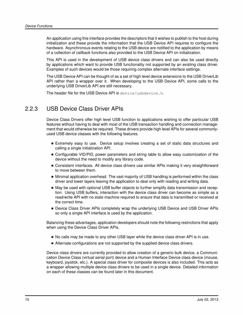
The USB audio device class provides a playback interface which allows an application to act as ageneric USB audio device to any host operating systems that natively supports USB audio devices.Most operating systems provide native support for generic audio class devices which means thatno operating system specific drivers are required. The USB audio device class provides a single16 bit stereo playback interface at 48kHz sample rate and also provides volume and mute controls.
USB
Hos
t
USB
Driv
er
USB
Dev
ice
API
Audi
o C
lass
Driv
er
Appl
icat
ion
Cod
e
Endpoint 0
IsochronousOUT
USB Audio Device Model
Empty Buffer
Audi
o Pl
ayba
ck
Filled Buffer
AudioMessages
Play
Free
July 02, 2013 11
Device Functions
2.3.1 Handling Audio Playback
The audio playback path is handled by the application passing buffers to be filled to the USB audioclass and receiving them back with audio data from the USB host controller. The USB audio classonly holds one buffer at a time and will return it to the application when it is full. Because the USBaudio class only holds one buffer, it is important to pass in a new buffer to the USB audio classas soon as possible once a buffer is returned to the application to prevent underflow from the USBhost controller. Since most audio playback methods uses at least two buffers, one that is playingand one that is being filled, the single buffer in the USB audio class allows for minimal buffering andeliminates copying of data between buffers. When the application has an audio buffer that needsto be filled it passes it to the USB audio class using the USBAudioBufferOut() function. The USBaudio class returns the buffer to the application via the audio message handler that the applica-tion provided in the pfnHandler member of the tUSBDAudioDevice structure. As soon as the audiodevice is active the application can provide a buffer to the USB audio class with a call to USBAu-dioBufferOut(). This call will only fail if the USB audio class already has a buffer, at this point theapplication must wait for a previous buffer to be returned with a USBD_AUDIO_EVENT_DATAOUTmessage. Once the USBD_AUDIO_EVENT_DATAOUT message is received, the buffer has beenfilled and can be played. The buffer provided may not be completely full so the application shouldonly play the portion of the buffer indicated by the message. To prevent underflow the applicationshould always be sure that the audio device class has an empty buffer to fill as soon as a filled bufferis returned. The USB audio class does not provide a way to stop playing audio because typicallywhen the USB host controller stops playing audio the host will simply stop providing data to theUSB audio device and playback will stop. This will not result in any notification to the applicationother than USBD_AUDIO_EVENT_DATAOUT messages will stop being received. If the applicationneeds to stop receiving data, it can simply stop providing buffers to the USB audio class and theaudio class will ignore any incoming data from the USB host controller.
2.3.2 Handling Other Audio Messages
The USB audio class also provides a few other notification messages to the application. Theseare the USBD_AUDIO_EVENT_VOLUME and USBD_AUDIO_EVENT_MUTE messages whichare both inform the application of volume and mute changes in the playback stream. TheUSBD_AUDIO_EVENT_VOLUME message returns a value that ranges from 0 - 100 in percent-age for the playback volume. The USBD_AUDIO_EVENT_MUTE is either zero indicating that theplayback path is not muted or 1 indicating that the playback path is muted. The application shouldalways take care to defer any lenghty processing of messages to its non-callback routines to preventunderflow/overflow conditions from occuring.
2.3.3 Using the Generic Audio Device Class
To add USB Audio data playback capability to your application via the Audio Device Class Driver,take the following steps.
Add the following header files to the source file(s) which are to support USB:
#include "src/usb.h"#include "usblib/usblib.h"#include "usblib/device/usbdevice.h"#include "usblib/device/usbdaudio.h"
12 July 02, 2013

Device Functions
Define the six entry string descriptor table which is used to describe various features ofyour new device to the host system. The following is the string table taken from theusb_dev_audio example application. Edit the actual strings to suit your application andtake care to ensure that you also update the length field (the first byte) of each descriptor tocorrectly reflect the length of the string and descriptor header. The number of string descrip-tors you include must be (1 + (5 ∗ num languages)) where the number of languages agreeswith the list published in string descriptor 0, g_pLangDescriptor . The strings for each languagemust be grouped together with all the language 1 strings before all the language 2 strings andso on.
//*****************************************************************************//// The languages supported by this device.////*****************************************************************************const uint8_t g_pui8LangDescriptor[] ={
4,USB_DTYPE_STRING,USBShort(USB_LANG_EN_US)
};
//*****************************************************************************//// The manufacturer string.////*****************************************************************************const uint8_t g_pui8ManufacturerString[] ={
(17 + 1) * 2,USB_DTYPE_STRING,’T’, 0, ’e’, 0, ’x’, 0, ’a’, 0, ’s’, 0, ’ ’, 0, ’I’, 0, ’n’, 0, ’s’, 0,’t’, 0, ’r’, 0, ’u’, 0, ’m’, 0, ’e’, 0, ’n’, 0, ’t’, 0, ’s’, 0,
};
//*****************************************************************************//// The product string.////*****************************************************************************const uint8_t g_pui8ProductString[] ={
(13 + 1) * 2,USB_DTYPE_STRING,’A’, 0, ’u’, 0, ’d’, 0, ’i’, 0, ’o’, 0, ’ ’, 0, ’E’, 0, ’x’, 0, ’a’, 0,’m’, 0, ’p’, 0, ’l’, 0, ’e’, 0
};
//*****************************************************************************//// The serial number string.////*****************************************************************************const uint8_t g_pui8SerialNumberString[] ={
(8 + 1) * 2,USB_DTYPE_STRING,’1’, 0, ’2’, 0, ’3’, 0, ’4’, 0, ’5’, 0, ’6’, 0, ’7’, 0, ’8’, 0
};
//*****************************************************************************//// The interface description string.//
July 02, 2013 13
Device Functions
//*****************************************************************************const uint8_t g_pui8HIDInterfaceString[] ={
(15 + 1) * 2,USB_DTYPE_STRING,’A’, 0, ’u’, 0, ’d’, 0, ’i’, 0, ’o’, 0, ’ ’, 0, ’I’, 0, ’n’, 0,’t’, 0, ’e’, 0, ’r’, 0, ’f’, 0, ’a’, 0, ’c’, 0, ’e’, 0
};
//*****************************************************************************//// The configuration description string.////*****************************************************************************const uint8_t g_pui8ConfigString[] ={
(20 + 1) * 2,USB_DTYPE_STRING,’A’, 0, ’u’, 0, ’d’, 0, ’i’, 0, ’o’, 0, ’ ’, 0, ’ ’, 0, ’C’, 0,’o’, 0, ’n’, 0, ’f’, 0, ’i’, 0, ’g’, 0, ’u’, 0, ’r’, 0, ’a’, 0,’t’, 0, ’i’, 0, ’o’, 0, ’n’, 0
};
//*****************************************************************************//// The descriptor string table.////*****************************************************************************const uint8_t * const g_ppui8StringDescriptors[] ={
g_pui8LangDescriptor,g_pui8ManufacturerString,g_pui8ProductString,g_pui8SerialNumberString,g_pui8HIDInterfaceString,g_pui8ConfigString
};
#define NUM_STRING_DESCRIPTORS (sizeof(g_ppui8StringDescriptors) / \sizeof(uint8_t *))
Define a tUSBDAudioDevice structure and initialize all fields as required for your application.
const tUSBDAudioDevice g_sAudioDevice ={
//// The Vendor ID you have been assigned by USB-IF.//USB_VID_YOUR_VENDOR_ID,
//// The product ID you have assigned for this device.//USB_PID_YOUR_PRODUCT_ID,
//// The vendor string for your device (8 chars).//USB_YOUR_VENDOR_STRING,
//// The product string for your device (16 chars).//USB_YOUR_PRODUCT_STRING,
//
14 July 02, 2013

Device Functions
// The revision string for your device (4 chars BCD).//USB_YOUR_REVISION_STRING,
//// The power consumption of your device in milliamps.//POWER_CONSUMPTION_MA,
//// The value to be passed to the host in the USB configuration descriptor’s// bmAttributes field.//USB_CONF_ATTR_SELF_PWR,
//// A pointer to your control callback event handler.//YourUSBAudioMessageHandler,
//// A pointer to your string table.//g_ppui8StringDescriptors,
//// The number of entries in your string table.//NUM_STRING_DESCRIPTORS,
//// Maximum volume setting expressed as and 8.8 signed fixed point number.//VOLUME_MAX,
//// Minimum volume setting expressed as and 8.8 signed fixed point number.//VOLUME_MIN,
//// Minimum volume step expressed as and 8.8 signed fixed point number.//VOLUME_STEP
};
From your main initialization function call the audio device class driver initialization function toconfigure the USB controller and place the device on the bus.
pvDevice = USBDAudioInit(0, &g_sAudioDevice);
Assuming pvDevice returned is not NULL, your device is now ready to communicate with aUSB host.
Once the host connects, the audio message handler will be sent theUSB_EVENT_CONNECTED event.
Once the host is configured to use the Audio device the audio message handler will be calledwith a USBD_AUDIO_EVENT_ACTIVE event.
July 02, 2013 15
Device Functions
2.3.4 Using the Audio Device Class in a Composite Device
When using the audio device class in a composite device, the configuration of the device is verysimilar to how it is configured as a non-composite device. Follow all of the configuration steps inthe previous section with the exception of calling USBDAudioCompositeInit() instead of USBDAu-dioInit(). This will prepare an instance of the audio device class to be enumerated as part of acomposite device. The USBDAudioCompositeInit() function takes the audio device structure and apointer to a tCompositeEntry value so that it can properly initialize the audio device and the com-posite entry that will later be passed to the USBDCompositeInit() funtion. The code example belowprovides an example of how to initialize an audio device to be a part of a composite device.
//// These should be initialized with valid values for each class.//extern tUSBDAudioDevice g_sAudioDevice;void *pvAudioDevice;
//// The array of composite device entries.//tCompositeEntry psCompEntries[2];
//// Allocate the device data for the top level composite device class.//tUSBDCompositeDevice g_sCompDevice ={
//// Texas Intruments C-Series VID.//USB_VID_TI_1CBE,
//// Texas Intruments C-Series PID for composite serial device.//USB_PID_YOUR_COMPOSITE_PID,
//// This is in 2mA increments so 500mA.//250,
//// Bus powered device.//USB_CONF_ATTR_BUS_PWR,
//// Composite event handler.//EventHandler,
//// The string table.//g_pui8StringDescriptors,NUM_STRING_DESCRIPTORS,
//// The Composite device array.//2,g_psCompEntries
16 July 02, 2013
Device Functions
};
//// The OTHER_SIZES here are the sizes of the descriptor data for other classes// that are part of the composite device.//#define DESCRIPTOR_DATA_SIZE (COMPOSITE_DAUDIO_SIZE + OTHER_SIZES)uint8_t g_pui8DescriptorData[DESCRIPTOR_DATA_SIZE];
//// Initialize the audio device and its composite entry which is entry 0.//pvAudioDevice = USBDAudioCompositeInit(0, &g_sAudioDevice, &psCompEntries[0]);
//// Initialize other devices to add to the composite device.//
...
USBDCompositeInit(0, &g_sCompDevice, DESCRIPTOR_DATA_SIZE,g_pui8DescriptorData);
All other API calls to the USB audio device class should use the value returned by USBDAudio-CompositeInit() when the APIs call for a pvInstance pointer. Also when using the audio devicein a composite device the COMPOSITE_DAUDIO_SIZE value should be added to the size of theg_pui8DescriptorData array as shown in the example above.
2.3.5 Audio Device Class Events
The audio device class driver sends the following events to the application callback functions:
USBD_AUDIO_EVENT_IDLE - Audio interface is idle.
USBD_AUDIO_EVENT_ACTIVE - Audio interface is active.
USBD_AUDIO_EVENT_DATAOUT - Audio playback buffer released.
USBD_AUDIO_EVENT_VOLUME - Audio playback volume change.
USBD_AUDIO_EVENT_MUTE - Audio mute change.
2.4 Audio Device Class Driver Definitions
Data StructurestUSBDAudioDevice
DefinesCOMPOSITE_DAUDIO_SIZEUSBD_AUDIO_EVENT_ACTIVEUSBD_AUDIO_EVENT_DATAOUTUSBD_AUDIO_EVENT_IDLE
July 02, 2013 17

Device Functions
USBD_AUDIO_EVENT_MUTEUSBD_AUDIO_EVENT_VOLUME
Functionsint32_t USBAudioBufferOut (void ∗pvAudioDevice, void ∗pvBuffer, uint32_t ui32Size, tUSBAu-dioBufferCallback pfnCallback)void ∗ USBDAudioCompositeInit (uint32_t ui32Index, tUSBDAudioDevice ∗psAudioDevice,tCompositeEntry ∗psCompEntry)void ∗ USBDAudioInit (uint32_t ui32Index, tUSBDAudioDevice ∗psAudioDevice)void USBDAudioTerm (void ∗pvAudioDevice)
2.4.1 Detailed Description
The macros and functions defined in this section can be found in header filedevice/usbdaudio.h.
2.4.2 Data Structure Documentation
2.4.2.1 tUSBDAudioDevice
Definition:typedef struct{
const uint16_t ui16VID;const uint16_t ui16PID;const char pcVendor[8];const char pcProduct[16];const char pcVersion[4];const uint16_t ui16MaxPowermA;const uint8_t ui8PwrAttributes;tUSBCallbackconst pfnCallback;const uint8_t *const *ppui8StringDescriptors;const uint32_t ui32NumStringDescriptors;const int16_t i16VolumeMax;const int16_t i16VolumeMin;const int16_t i16VolumeStep;tAudioInstance sPrivateData;
}tUSBDAudioDevice
Members:ui16VID The vendor ID that this device is to present in the device descriptor.ui16PID The product ID that this device is to present in the device descriptor.pcVendor 8 byte vendor string.pcProduct 16 byte vendor string.pcVersion 4 byte vendor string.
18 July 02, 2013
Device Functions
ui16MaxPowermA The maximum power consumption of the device, expressed in mA.ui8PwrAttributes Indicates whether the device is self or bus-powered and whether or
not it supports remote wake up. Valid values are USB_CONF_ATTR_SELF_PWR orUSB_CONF_ATTR_BUS_PWR, optionally ORed with USB_CONF_ATTR_RWAKE.
pfnCallback A pointer to the callback function which will be called to notify the application ofevents relating to the operation of the audio device.
ppui8StringDescriptors A pointer to the string descriptor array for this device. This arraymust contain the following string descriptor pointers in this order. Language descriptor,Manufacturer name string (language 1), Product name string (language 1), Serial numberstring (language 1), Audio Interface description string (language 1), Configuration descrip-tion string (language 1).If supporting more than 1 language, the descriptor block (except for string descriptor 0)must be repeated for each language defined in the language descriptor.
ui32NumStringDescriptors The number of descriptors provided in the ppStringDescriptorsarray. This must be 1 + ((5 + (number of strings)) * (number of languages)).
i16VolumeMax The maximum volume expressed as an 8.8 signed value.i16VolumeMin The minimum volume expressed as an 8.8 signed value.i16VolumeStep The minimum volume step expressed as an 8.8 signed value.sPrivateData The private instance data for the audio device.
Description:The structure used by the application to define operating parameters for the device audio class.
2.4.3 Define Documentation
2.4.3.1 COMPOSITE_DAUDIO_SIZE
Definition:#define COMPOSITE_DAUDIO_SIZE
Description:The size of the memory that should be allocated to create a configuration descriptor for a singleinstance of the USB Audio Device. This does not include the configuration descriptor which isautomatically ignored by the composite device class.
2.4.3.2 USBD_AUDIO_EVENT_ACTIVE
Definition:#define USBD_AUDIO_EVENT_ACTIVE
Description:This USB audio event indicates that the device is connected and is now active.
2.4.3.3 USBD_AUDIO_EVENT_DATAOUT
Definition:#define USBD_AUDIO_EVENT_DATAOUT
July 02, 2013 19
Device Functions
Description:This USB audio event indicates that the device is returning a data buffer provided by the US-BAudioBufferOut() function back to the application with valid audio data received from the USBhost controller. The pvBuffer parameter holds the pointer to the buffer with the new audio dataand the ui32Param value holds the amount of valid data in bytes that are contained in thepvBuffer parameter.
2.4.3.4 USBD_AUDIO_EVENT_IDLE
Definition:#define USBD_AUDIO_EVENT_IDLE
Description:This USB audio event indicates that the device is connected but not active.
2.4.3.5 USBD_AUDIO_EVENT_MUTE
Definition:#define USBD_AUDIO_EVENT_MUTE
Description:This USB audio event indicates that a mute request has occurred. The ui32Param value willeither be a 1 to indicate that the audio is now muted, and a value of 0 indicates that the audiohas been unmuted.
2.4.3.6 USBD_AUDIO_EVENT_VOLUME
Definition:#define USBD_AUDIO_EVENT_VOLUME
Description:This USB audio event indicates that a volume change has occurred. The ui32Param valuecontains a signed 8.8 fixed point value that represents the current volume gain/attenuationin decibels(dB). The provided message handler should be prepared to handle negative andpositive values with the value 0x8000 indicating maximum attenuation. The pvBuffer parametershould be ignored.
2.4.4 Function Documentation
2.4.4.1 USBAudioBufferOut
This function is used to supply buffers to the audio class to be filled from the USB host device.
Prototype:int32_tUSBAudioBufferOut(void *pvAudioDevice,
void *pvBuffer,
20 July 02, 2013
Device Functions
uint32_t ui32Size,tUSBAudioBufferCallback pfnCallback)
Parameters:pvAudioDevice is the pointer to the device instance structure as returned by USBDAudioInit()
or USBDAudioCompositeInit().pvBuffer is a pointer to the buffer to fill with audio data.ui32Size is the size in bytes of the buffer pointed to by the pvBuffer parameter.pfnCallback is a callback that will provide notification when this buffer has valid data.
Description:This function fills the buffer pointed to by the pvBuffer parameter with at mostui32Size one packet of data from the host controller. The ui32Size has a min-imum value of ISOC_OUT_EP_MAX_SIZE since each USB packet can be at mostISOC_OUT_EP_MAX_SIZE bytes in size. Since the audio data may not be received inamounts that evenly fit in the buffer provided, the buffer may not be completely filled. ThepfnCallback function will provide the amount of valid data that was actually stored in the bufferprovided. The function will return zero if the buffer could be scheduled to be filled, otherwisethe function will return a non-zero value if there was some reason that the buffer could not beadded.
Returns:Returns 0 to indicate success any other value indicates that the buffer will not be filled.
2.4.4.2 USBDAudioCompositeInit
This function should be called once for the audio class device to initialized basic operation andprepare for enumeration.
Prototype:void *USBDAudioCompositeInit(uint32_t ui32Index,
tUSBDAudioDevice *psAudioDevice,tCompositeEntry *psCompEntry)
Parameters:ui32Index is the index of the USB controller to initialize for audio class device operation.psAudioDevice points to a structure containing parameters customizing the operation of the
audio device.psCompEntry is the composite device entry to initialize when creating a composite device.
Description:In order for an application to initialize the USB audio device class, it must first call this functionwith the a valid audio device class structure in the psAudioDevice parameter. This allowsthis function to initialize the USB controller and device code to be prepared to enumerate andfunction as a USB audio device. When this audio device is part of a composite device, then thepsCompEntry should point to the composite device entry to initialize. This is part of the arraythat is passed to the USBDCompositeInit() function.
This function returns a void pointer that must be passed in to all other APIs used by the audioclass.
July 02, 2013 21

Device Functions
See the documentation on the tUSBDAudioDevice structure for more information on how toproperly fill the structure members.
Returns:Returns zero on failure or a non-zero instance value that should be used with the remainingUSB audio APIs.
2.4.4.3 USBDAudioInit
This function should be called once for the audio class device to initialized basic operation andprepare for enumeration.
Prototype:void *USBDAudioInit(uint32_t ui32Index,
tUSBDAudioDevice *psAudioDevice)
Parameters:ui32Index is the index of the USB controller to initialize for audio class device operation.psAudioDevice points to a structure containing parameters customizing the operation of the
audio device.
Description:In order for an application to initialize the USB audio device class, it must first call this functionwith the a valid audio device class structure in the psAudioDevice parameter. This allowsthis function to initialize the USB controller and device code to be prepared to enumerate andfunction as a USB audio device.
This function returns a void pointer that must be passed in to all other APIs used by the audioclass.
See the documentation on the tUSBDAudioDevice structure for more information on how toproperly fill the structure members.
Returns:Returns 0 on failure or a non-zero void pointer on success.
2.4.4.4 USBDAudioTerm
Shuts down the audio device.
Prototype:voidUSBDAudioTerm(void *pvAudioDevice)
Parameters:pvAudioDevice is the pointer to the device instance structure as returned by USBDAudioInit().
Description:This function terminates audio interface for the instance supplied. This function should not becalled if the audio device is part of a composite device and instead the USBDCompositeTerm()function should be called for the full composite device. Following this call, the pvAudioDeviceinstance should not me used in any other calls.
22 July 02, 2013
Device Functions
Returns:None.
2.5 Bulk Device Class Driver
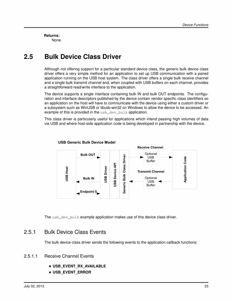
Although not offering support for a particular standard device class, the generic bulk device classdriver offers a very simple method for an application to set up USB communication with a pairedapplication running on the USB host system. The class driver offers a single bulk receive channeland a single bulk transmit channel and, when coupled with USB buffers on each channel, providesa straightforward read/write interface to the application.
The device supports a single interface containing bulk IN and bulk OUT endpoints. The configu-ration and interface descriptors published by the device contain vendor specific class identifiers soan application on the host will have to communicate with the device using either a custom driver ora subsystem such as WinUSB or libusb-win32 on Windows to allow the device to be accessed. Anexample of this is provided in the usb_dev_bulk application.
This class driver is particularly useful for applications which intend passing high volumes of datavia USB and where host-side application code is being developed in partnership with the device.
OptionalUSBBuffer
OptionalUSBBuffer
USB
Hos
t
USB
Driv
er
USB
Dev
ice
API
Gen
eric
Bul
k C
lass
Driv
er
Appl
icat
ion
Cod
e
Endpoint 0
Bulk OUT
Bulk IN
Receive Channel
Transmit Channel
USB Generic Bulk Device Model
The usb_dev_bulk example application makes use of this device class driver.
2.5.1 Bulk Device Class Events
The bulk device class driver sends the following events to the application callback functions:
2.5.1.1 Receive Channel Events
USB_EVENT_RX_AVAILABLE
USB_EVENT_ERROR
July 02, 2013 23

Device Functions
USB_EVENT_CONNECTED
USB_EVENT_DISCONNECTED
USB_EVENT_SUSPEND
USB_EVENT_RESUME
Note: The USB_EVENT_DISCONNECTED event will not be reported to the application if theMCU’s PB1/USB0VBUS pin is connected to a fixed +5 Volts rather than directly to the VBUS pin onthe USB connector or if the USB controller is configured to force device mode.
2.5.1.2 Transmit Channel Events
USB_EVENT_TX_COMPLETE
2.5.2 Using the Generic Bulk Device Class
To add USB bulk data transmit and receive capability to your application via the Generic Bulk DeviceClass Driver, take the following steps.
Add the following header files to the source file(s) which are to support USB:
#include "src/usb.h"#include "usblib/usblib.h"#include "usblib/device/usbdevice.h"#include "usblib/device/usbdbulk.h"
Define the 5 entry string table which is used to describe various features of your new deviceto the host system. The following is the string table taken from the usb_dev_bulk exampleapplication. Edit the actual strings to suit your application and take care to ensure that youalso update the length field (the first byte) of each descriptor to correctly reflect the length ofthe string and descriptor header. The number of strings you include must be 5 ∗ (number oflanguages listed in string descriptor 0, g_pLangDescriptor , and the strings for each languagemust be grouped together with all the language 1 strings before all the language 2 strings andso on.
//*****************************************************************************//// The languages supported by this device.////*****************************************************************************const uint8_t g_pui8LangDescriptor[] ={
4,USB_DTYPE_STRING,USBShort(USB_LANG_EN_US)
};
//*****************************************************************************//// The manufacturer string.////*****************************************************************************const uint8_t g_pui8ManufacturerString[] ={
(17 + 1) * 2,USB_DTYPE_STRING,
24 July 02, 2013
Device Functions
’T’, 0, ’e’, 0, ’x’, 0, ’a’, 0, ’s’, 0, ’ ’, 0, ’I’, 0, ’n’, 0, ’s’, 0,’t’, 0, ’r’, 0, ’u’, 0, ’m’, 0, ’e’, 0, ’n’, 0, ’t’, 0, ’s’, 0,
};
//*****************************************************************************//// The product string.////*****************************************************************************const uint8_t g_pui8ProductString[] ={
(19 + 1) * 2,USB_DTYPE_STRING,’G’, 0, ’e’, 0, ’n’, 0, ’e’, 0, ’r’, 0, ’i’, 0, ’c’, 0, ’ ’, 0, ’B’, 0,’u’, 0, ’l’, 0, ’k’, 0, ’ ’, 0, ’D’, 0, ’e’, 0, ’v’, 0, ’i’, 0, ’c’, 0,’e’, 0
};
//*****************************************************************************//// The serial number string.////*****************************************************************************const uint8_t g_pui8SerialNumberString[] ={
(8 + 1) * 2,USB_DTYPE_STRING,’1’, 0, ’2’, 0, ’3’, 0, ’4’, 0, ’5’, 0, ’6’, 0, ’7’, 0, ’8’, 0
};
//*****************************************************************************//// The data interface description string.////*****************************************************************************const uint8_t g_pui8DataInterfaceString[] ={
(19 + 1) * 2,USB_DTYPE_STRING,’B’, 0, ’u’, 0, ’l’, 0, ’k’, 0, ’ ’, 0, ’D’, 0, ’a’, 0, ’t’, 0,’a’, 0, ’ ’, 0, ’I’, 0, ’n’, 0, ’t’, 0, ’e’, 0, ’r’, 0, ’f’, 0,’a’, 0, ’c’, 0, ’e’, 0
};
//*****************************************************************************//// The configuration description string.////*****************************************************************************const uint8_t g_pui8ConfigString[] ={
(23 + 1) * 2,USB_DTYPE_STRING,’B’, 0, ’u’, 0, ’l’, 0, ’k’, 0, ’ ’, 0, ’D’, 0, ’a’, 0, ’t’, 0,’a’, 0, ’ ’, 0, ’C’, 0, ’o’, 0, ’n’, 0, ’f’, 0, ’i’, 0, ’g’, 0,’u’, 0, ’r’, 0, ’a’, 0, ’t’, 0, ’i’, 0, ’o’, 0, ’n’, 0
};
//*****************************************************************************//// The descriptor string table.////*****************************************************************************const uint8_t * const g_ppui8StringDescriptors[] ={
g_pui8LangDescriptor,
July 02, 2013 25
Device Functions
g_pui8ManufacturerString,g_pui8ProductString,g_pui8SerialNumberString,g_pui8DataInterfaceString,g_pui8ConfigString
};
#define NUM_STRING_DESCRIPTORS (sizeof(g_ppui8StringDescriptors) / \sizeof(uint8_t *))
Define a tUSBDBulkDevice structure and initialize all fields as required for your application.The following example illustrates a simple case where no USB buffers are in use. For an ex-ample using USB buffers, see the source file usb_bulk_structs.c in the usb_dev_bulkexample application.
const tUSBDBulkDevice g_sBulkDevice ={
//// The Vendor ID you have been assigned by USB-IF.//USB_VID_YOUR_VENDOR_ID,
//// The product ID you have assigned for this device.//USB_PID_YOUR_PRODUCT_ID,
//// The power consumption of your device in milliamps.//POWER_CONSUMPTION_MA,
//// The value to be passed to the host in the USB configuration descriptor’s// bmAttributes field.//USB_CONF_ATTR_SELF_PWR,
//// A pointer to your receive callback event handler.//YourUSBReceiveEventCallback,
//// A value that you want passed to the receive callback alongside every// event.//(void *)&g_sYourInstanceData,
//// A pointer to your transmit callback event handler.//YourUSBTransmitEventCallback,
//// A value that you want passed to the transmit callback alongside every// event.//(void *)&g_sYourInstanceData,
//// A pointer to your string table.//g_ppui8StringDescriptors,
26 July 02, 2013
Device Functions
//// The number of entries in your string table.//NUM_STRING_DESCRIPTORS
};
Add a receive event handler function, YourUSBReceiveEventCallback in the previous exam-ple, to your application taking care to handle all messages which require a particular response.For the generic bulk device class, only the USB_EVENT_RX_AVAILABLE MUST be handledby the receive event handler. In response to USB_EVENT_RX_AVAILABLE, your handlershould check the amount of data received by calling USBDBulkRxPacketAvailable() then readit using a call to USBDBulkPacketRead(). This causes the newly received data to be ac-knowledged to the host and instructs the host that it may now transmit another packet. If youare unable to read the data immediately, return 0 from the callback handler and you will becalled back once again a few milliseconds later. Although no other events must be handled,USB_EVENT_CONNECTED and USB_EVENT_DISCONNECTED will typically be requiredsince these indicate when a host connects or disconnects and allow the application to flushany buffers or reset state as required. Attempts to send data when the host is disconnectedwill fail.
Add a transmit event handler function, YourUSBTransmitEventCallback in the previous exam-ple, to your application taking care to handle all messages which require a particular response.For the generic bulk device class, there are no events sent to the transmit callback which MUSTbe handled but applications will usually want to note USB_EVENT_TX_COMPLETE since thisis an interlock message indicating that the previous packet sent has been acknowledged bythe host and a new packet can now be sent.
From your main initialization function call the generic bulk device class driver initializationfunction to configure the USB controller and place the device on the bus.
pvDevice = USBDBulkInit(0, &g_sBulkDevice);
Assuming pvDevice returned is not NULL, your device is now ready to communicate with aUSB host.
Once the host connects, your receive event handler will be sent USB_EVENT_CONNECTEDand the first packet of data may be sent to the host using USBDBulkPacketWrite() with follow-ing packets transmitted as soon as USB_EVENT_TX_COMPLETE is received.
2.5.3 Using the Bulk Device Class in a Composite Device
When using the bulk device class in a composite device, the configuration of the device is verysimilar to how it is configured as a non-composite device. Follow all of the configuration steps in theprevious section with the exception of calling USBDBulkCompositeInit() instead of USBDBulkInit().This will prepare an instance of the bulk device class to be enumerated as part of a compositedevice. The USBDBulkCompositeInit() function takes the bulk device structure and a pointer toa tCompositeEntry value so that it can properly initialize the bulk device and the composite entrythat will later be passed to the USBDCompositeInit() funtion. The code example below provides anexample of how to initialize a bulk device to be a part of a composite device.
//// These should be initialized with valid values for each class.//extern tUSBDBulkDevice g_sBulkDevice;void *pvBulkDevice;
July 02, 2013 27
Device Functions
//// The array of composite devices.//tCompositeEntry psCompEntries[2];
//// Allocate the device data for the top level composite device class.//tUSBDCompositeDevice g_sCompDevice ={
//// Texas Intruments C-Series VID.//USB_VID_TI_1CBE,
//// Texas Intruments C-Series PID for composite serial device.//USB_PID_YOUR_COMPOSITE_PID,
//// This is in 2mA increments so 500mA.//250,
//// Bus powered device.//USB_CONF_ATTR_BUS_PWR,
//// Composite event handler.//EventHandler,
//// The string table.//g_pui8StringDescriptors,NUM_STRING_DESCRIPTORS,
//// The Composite device array.//2,g_psCompEntries
};
//// The OTHER_SIZES here are the sizes of the descriptor data for other classes// that are part of the composite device.//#define DESCRIPTOR_DATA_SIZE (COMPOSITE_DBULK_SIZE + OTHER_SIZES)uint8_t g_pui8DescriptorData[DESCRIPTOR_DATA_SIZE];
//// Initialize the bulk device and its composite entry.//pvBulkDevice = USBDBulkCompositeInit(0, &g_sBulkDevice, &psCompEntries[0]);
//// Initialize other devices to add to the composite device.//
...
28 July 02, 2013
Device Functions
//// Initialize the USB controller as a composite device.//USBDCompositeInit(0, &g_sCompDevice, DESCRIPTOR_DATA_SIZE,
g_pui8DescriptorData);
All other API calls to the USB bulk device class should use the value returned by USBDBulk-CompositeInit() when the API calls for a pvInstance pointer. Also when using the bulk devicein a composite device the COMPOSITE_DBULK_SIZE value should be added to the size of theg_pui8DescriptorData array as shown in the example above.
2.5.4 Windows Drivers for Generic Bulk Devices
Since generic bulk devices appear to a host operating system as vendor-specific devices, no devicedrivers on the host system will be able to communicate with them without some help from the devicedeveloper. This help may involve writing a specific Windows kernel driver for the device or, if kerneldriver programming is too daunting, steering Windows to use one of several possible generic kerneldrivers that can manage the device on behalf of a user mode application.
Using this second model, a device developer need not write any Windows driver code but wouldneed to write an application or DLL that interfaces with the device via the user-mode API offered bywhichever USB subsystem they chose to manage their device. The developer is also responsiblefor producing a suitable INF file to allow Windows to associate the device (identified via its VID/PIDcombination) with a particular driver.
A least two suitable USB subsystems are available for Windows - WinUSB from Microsoft or open-source project libusb-win32 available from SourceForge.
WinUSB supports WindowsXP, Windows Vista and Windows7 systems. Further information can beobtained from MSDN at http://msdn.microsoft.com/en-us/library/aa476426.aspx.To develop applications using the WinUSB interface, the Windows Driver Development Kit (DDK)must be installed on your build PC. This interface is currently used by the Windows example ap-plications, "Oscilloscope" and "USB Bulk Example". These applications can be found in package"PDL-LM3S-win" which may be downloaded via a link on http://www.ti.com/tivaware.
libusb-win32 supports Windows98SE, Windows2000, WindowsNT and WindowsXP and can bedownloaded from http://libusb-win32.sourceforge.net/. It offers a straightforwardmethod of accessing the device and also provides a very helpful INF file generator.
2.5.4.1 Sample WinUSB INF file
This file illustrates how to build an INF to associate your device with the WinUSB subsystem onWindowsXP or Vista. Note that the driver package for the device must include not only this INFfile but the Microsoft-supplied coinstallers listed in the files section. These can be found within theWindows Driver Development Kit (DDK).
; -----------------------------------------------------------------------------;; USBLib Generic Bulk USB device driver installer;; This INF file may be used as a template when creating customized applications; based on the USBLib generic bulk devices. Areas of the file requiring; customization for a new device are commented with NOTEs.;
July 02, 2013 29

Device Functions
; -----------------------------------------------------------------------------
; NOTE: When you customize this INF for your own device, create a new class; name (Class) and a new GUID (ClassGuid). GUIDs may be created using the; guidgen tool from Windows Visual Studio.
[Version]Signature = "$Windows NT$"Class = USBLibBulkDeviceClassClassGuid={F5450C06-EB58-420e-8F98-A76C5D4AFB18}Provider = %ProviderName%CatalogFile=MyCatFile.cat
; ========== Manufacturer/Models sections ===========
[Manufacturer]%ProviderName% = USBLibBulkDevice_WinUSB,NTx86,NTamd64
; NOTE: Replace the VID and PID in the following two sections with the; correct values for your device.
[USBLibBulkDevice_WinUSB.NTx86]%USB\USBLibBulkDevice.DeviceDesc% =USB_Install, USB\VID_1CBE&PID_0003
[USBLibBulkDevice_WinUSB.NTamd64]%USB\USBLibBulkDevice.DeviceDesc% =USB_Install, USB\VID_1CBE&PID_0003
; =================== Installation ===================
[ClassInstall32]AddReg=AddReg_ClassInstall
[AddReg_ClassInstall]HKR,,,,"%DeviceClassDisplayName%"HKR,,Icon,,"-20"
[USB_Install]Include=winusb.infNeeds=WINUSB.NT
[USB_Install.Services]Include=winusb.infAddService=WinUSB,0x00000002,WinUSB_ServiceInstall
[WinUSB_ServiceInstall]DisplayName = %WinUSB_SvcDesc%ServiceType = 1StartType = 3ErrorControl = 1ServiceBinary = %12%\WinUSB.sys
[USB_Install.Wdf]KmdfService=WINUSB, WinUsb_Install
[WinUSB_Install]KmdfLibraryVersion=1.5
[USB_Install.HW]AddReg=Dev_AddReg
; NOTE: Create a new GUID for your interface and replace the following one; when customizing for a new device.
[Dev_AddReg]HKR,,DeviceInterfaceGUIDs,0x10000,"{6E45736A-2B1B-4078-B772-B3AF2B6FDE1C}"
30 July 02, 2013
Device Functions
[USB_Install.CoInstallers]AddReg=CoInstallers_AddRegCopyFiles=CoInstallers_CopyFiles
[CoInstallers_AddReg]HKR,,CoInstallers32,0x00010000,"WdfCoInstaller01005.dll,WdfCoInstaller","WinUSBCoInstaller.dll"
[CoInstallers_CopyFiles]WinUSBCoInstaller.dllWdfCoInstaller01005.dll
[DestinationDirs]CoInstallers_CopyFiles=11
; ================= Source Media Section =====================
[SourceDisksNames]1 = %DISK_NAME%,,,\i3862 = %DISK_NAME%,,,\amd64
[SourceDisksFiles.x86]WinUSBCoInstaller.dll=1WdfCoInstaller01005.dll=1
[SourceDisksFiles.amd64]WinUSBCoInstaller.dll=2WdfCoInstaller01005.dll=2
; =================== Strings ===================
; Note: Replace these as appropriate to describe your device.
[Strings]ProviderName="Texas Instruments"USB\USBLibBulkDevice.DeviceDesc="Generic Bulk Device"WinUSB_SvcDesc="WinUSB"DISK_NAME="USBLib Install Disk"DeviceClassDisplayName="USBLib Bulk Devices"
2.5.4.2 Sample libusb-win32 INF File
The following is an example of an INF file that can be used to associate the usb_dev_bulk ex-ample device with the libusb-win32 subsystem on Windows systems and to install the necessarydrivers. This was created using the "INF Wizard" application which is included in the libusb-win32download package.
[Version]Signature = "$Chicago$"provider = %manufacturer%DriverVer = 03/20/2007,0.1.12.1CatalogFile = usb_dev_bulk_libusb.catCatalogFile.NT = usb_dev_bulk_libusb.catCatalogFile.NTAMD64 = usb_dev_bulk_libusb_x64.cat
Class = LibUsbDevicesClassGUID = {EB781AAF-9C70-4523-A5DF-642A87ECA567}
[ClassInstall]AddReg=libusb_class_install_add_reg
[ClassInstall32]AddReg=libusb_class_install_add_reg
July 02, 2013 31
Device Functions
[libusb_class_install_add_reg]HKR,,,,"LibUSB-Win32 Devices"HKR,,Icon,,"-20"
[Manufacturer]%manufacturer%=Devices,NT,NTAMD64
;--------------------------------------------------------------------------; Files;--------------------------------------------------------------------------
[SourceDisksNames]1 = "Libusb-Win32 Driver Installation Disk",,
[SourceDisksFiles]libusb0.sys = 1,,libusb0.dll = 1,,libusb0_x64.sys = 1,,libusb0_x64.dll = 1,,
[DestinationDirs]libusb_files_sys = 10,system32\driverslibusb_files_sys_x64 = 10,system32\driverslibusb_files_dll = 10,system32libusb_files_dll_wow64 = 10,syswow64libusb_files_dll_x64 = 10,system32
[libusb_files_sys]libusb0.sys
[libusb_files_sys_x64]libusb0.sys,libusb0_x64.sys
[libusb_files_dll]libusb0.dll
[libusb_files_dll_wow64]libusb0.dll
[libusb_files_dll_x64]libusb0.dll,libusb0_x64.dll
;--------------------------------------------------------------------------; Device driver;--------------------------------------------------------------------------
[LIBUSB_DEV]CopyFiles = libusb_files_sys, libusb_files_dllAddReg = libusb_add_reg
[LIBUSB_DEV.NT]CopyFiles = libusb_files_sys, libusb_files_dll
[LIBUSB_DEV.NTAMD64]CopyFiles = libusb_files_sys_x64, libusb_files_dll_wow64, libusb_files_dll_x64
[LIBUSB_DEV.HW]DelReg = libusb_del_reg_hwAddReg = libusb_add_reg_hw
[LIBUSB_DEV.NT.HW]DelReg = libusb_del_reg_hwAddReg = libusb_add_reg_hw
[LIBUSB_DEV.NTAMD64.HW]
32 July 02, 2013
Device Functions
DelReg = libusb_del_reg_hwAddReg = libusb_add_reg_hw
[LIBUSB_DEV.NT.Services]AddService = libusb0, 0x00000002, libusb_add_service
[LIBUSB_DEV.NTAMD64.Services]AddService = libusb0, 0x00000002, libusb_add_service
[libusb_add_reg]HKR,,DevLoader,,*ntkernHKR,,NTMPDriver,,libusb0.sys
; Older versions of this .inf file installed filter drivers. They are not; needed any more and must be removed[libusb_del_reg_hw]HKR,,LowerFiltersHKR,,UpperFilters
; Device properties[libusb_add_reg_hw]HKR,,SurpriseRemovalOK, 0x00010001, 1
;--------------------------------------------------------------------------; Services;--------------------------------------------------------------------------
[libusb_add_service]DisplayName = "LibUsb-Win32 - Kernel Driver 03/20/2007, 0.1.12.1"ServiceType = 1StartType = 3ErrorControl = 0ServiceBinary = %12%\libusb0.sys
;--------------------------------------------------------------------------; Devices;--------------------------------------------------------------------------
[Devices]"Generic Bulk Device"=LIBUSB_DEV, USB\VID_1cbe&PID_0003
[Devices.NT]"Generic Bulk Device"=LIBUSB_DEV, USB\VID_1cbe&PID_0003
[Devices.NTAMD64]"Generic Bulk Device"=LIBUSB_DEV, USB\VID_1cbe&PID_0003
;--------------------------------------------------------------------------; Strings;--------------------------------------------------------------------------
[Strings]manufacturer = "Texas Instruments"
2.6 Bulk Device Class Driver Definitions
Data StructurestUSBDBulkDevice
July 02, 2013 33

Device Functions
DefinesCOMPOSITE_DBULK_SIZE
Functionsvoid ∗ USBDBulkCompositeInit (uint32_t ui32Index, tUSBDBulkDevice ∗psBulkDevice, tCom-positeEntry ∗psCompEntry)void ∗ USBDBulkInit (uint32_t ui32Index, tUSBDBulkDevice ∗psBulkDevice)uint32_t USBDBulkPacketRead (void ∗pvBulkDevice, uint8_t ∗pi8Data, uint32_t ui32Length,bool bLast)uint32_t USBDBulkPacketWrite (void ∗pvBulkDevice, uint8_t ∗pi8Data, uint32_t ui32Length,bool bLast)void USBDBulkPowerStatusSet (void ∗pvBulkDevice, uint8_t ui8Power)bool USBDBulkRemoteWakeupRequest (void ∗pvBulkDevice)uint32_t USBDBulkRxPacketAvailable (void ∗pvBulkDevice)void ∗ USBDBulkSetRxCBData (void ∗pvBulkDevice, void ∗pvCBData)void ∗ USBDBulkSetTxCBData (void ∗pvBulkDevice, void ∗pvCBData)void USBDBulkTerm (void ∗pvBulkDevice)uint32_t USBDBulkTxPacketAvailable (void ∗pvBulkDevice)
2.6.1 Detailed Description
The macros and functions defined in this section can be found in header file device/usbdbulk.h.
2.6.2 Data Structure Documentation
2.6.2.1 tUSBDBulkDevice
Definition:typedef struct{
const uint16_t ui16VID;const uint16_t ui16PID;const uint16_t ui16MaxPowermA;const uint8_t ui8PwrAttributes;tUSBCallbackconst pfnRxCallback;void *pvRxCBData;tUSBCallbackconst pfnTxCallback;void *pvTxCBData;const uint8_t *const *ppui8StringDescriptors;const uint32_t ui32NumStringDescriptors;tBulkInstance sPrivateData;
}tUSBDBulkDevice
Members:ui16VID The vendor ID that this device is to present in the device descriptor.
34 July 02, 2013

Device Functions
ui16PID The product ID that this device is to present in the device descriptor.ui16MaxPowermA The maximum power consumption of the device, expressed in milliamps.ui8PwrAttributes Indicates whether the device is self- or bus-powered and whether or
not it supports remote wakeup. Valid values are USB_CONF_ATTR_SELF_PWR orUSB_CONF_ATTR_BUS_PWR, optionally ORed with USB_CONF_ATTR_RWAKE.
pfnRxCallback A pointer to the callback function which will be called to notify the applicationof events related to the device’s data receive channel.
pvRxCBData A client-supplied pointer which will be sent as the first parameter in all callsmade to the receive channel callback, pfnRxCallback.
pfnTxCallback A pointer to the callback function which will be called to notify the applicationof events related to the device’s data transmit channel.
pvTxCBData A client-supplied pointer which will be sent as the first parameter in all callsmade to the transmit channel callback, pfnTxCallback.
ppui8StringDescriptors A pointer to the string descriptor array for this device. This arraymust contain pointers to the following string descriptors in this order. Language descriptor,Manufacturer name string (language 1), Product name string (language 1), Serial numberstring (language 1), Interface description string (language 1) and Configuration descriptionstring (language 1).If supporting more than 1 language, the strings for indices 1 through 5 must be repeatedfor each of the other languages defined in the language descriptor.
ui32NumStringDescriptors The number of descriptors provided in the ppStringDescriptorsarray. This must be 1 + (5 * number of supported languages).
sPrivateData The private instance data for this device. This memory must not be modified byany code outside the bulk class driver.
Description:The structure used by the application to define operating parameters for the bulk device.
2.6.3 Define Documentation
2.6.3.1 COMPOSITE_DBULK_SIZE
Definition:#define COMPOSITE_DBULK_SIZE
Description:The size of the memory that should be allocated to create a configuration descriptor for a singleinstance of the USB Bulk Device. This does not include the configuration descriptor which isautomatically ignored by the composite device class.
2.6.4 Function Documentation
2.6.4.1 USBDBulkCompositeInit
Initializes bulk device operation for a given USB controller.
Prototype:void *USBDBulkCompositeInit(uint32_t ui32Index,
July 02, 2013 35
Device Functions
tUSBDBulkDevice *psBulkDevice,tCompositeEntry *psCompEntry)
Parameters:ui32Index is the index of the USB controller which is to be initialized for bulk device operation.psBulkDevice points to a structure containing parameters customizing the operation of the
bulk device.psCompEntry is the composite device entry to initialize when creating a composite device.
Description:This call is very similar to USBDBulkInit() except that it is used for initializing an instance of thebulk device for use in a composite device. When this bulk device is part of a composite device,then the psCompEntry should point to the composite device entry to initialize. This is part ofthe array that is passed to the USBDCompositeInit() function.
Returns:Returns zero on failure or a non-zero value that should be used with the remaining USB BulkAPIs.
2.6.4.2 USBDBulkInit
Initializes bulk device operation for a given USB controller.
Prototype:void *USBDBulkInit(uint32_t ui32Index,
tUSBDBulkDevice *psBulkDevice)
Parameters:ui32Index is the index of the USB controller which is to be initialized for bulk device operation.psBulkDevice points to a structure containing parameters customizing the operation of the
bulk device.
Description:An application wishing to make use of a USB bulk communication channel must call this func-tion to initialize the USB controller and attach the device to the USB bus. This function performsall required USB initialization.
On successful completion, this function will return the psBulkDevice pointer passed to it. Thismust be passed on all future calls to the device driver related to this device.
The USBDBulk interface offers packet-based transmit and receive operation. If the applicationwould rather use block based communication with transmit and receive buffers, USB buffersmay be used above the bulk transmit and receive channels to offer this functionality.
Transmit Operation:
Calls to USBDBulkPacketWrite must send no more than 64 bytes of data at a time and mayonly be made when no other transmission is currently outstanding.
Once a packet of data has been acknowledged by the USB host, aUSB_EVENT_TX_COMPLETE event is sent to the application callback to inform it thatanother packet may be transmitted.
Receive Operation:
36 July 02, 2013
Device Functions
An incoming USB data packet will result in a call to the application callback with eventUSBD_EVENT_RX_AVAILABLE. The application must then call USBDBulkPacketRead(),passing a buffer capable of holding 64 bytes, to retrieve the data and acknowledge receptionto the USB host.
Note:The application must not make any calls to the low level USB Device API if interacting with USBvia the USB bulk device class API. Doing so will cause unpredictable (though almost certainlyunpleasant) behavior.
Returns:Returns NULL on failure or void pointer that should be used with the remaining USB bulk classAPSs.
2.6.4.3 USBDBulkPacketRead
Reads a packet of data received from the USB host via the bulk data interface.
Prototype:uint32_tUSBDBulkPacketRead(void *pvBulkDevice,
uint8_t *pi8Data,uint32_t ui32Length,bool bLast)
Parameters:pvBulkDevice is the pointer to the device instance structure as returned by USBDBulkInit().pi8Data points to a buffer into which the received data will be written.ui32Length is the size of the buffer pointed to by pi8Data.bLast indicates whether the client will make a further call to read additional data from the
packet.
Description:This function reads up to ui32Length bytes of data received from the USB host into the suppliedapplication buffer. If the driver detects that the entire packet has been read, it is acknowledgedto the host.
The bLast parameter is ignored in this implementation since the end of a packet can be deter-mined without relying upon the client to provide this information.
Returns:Returns the number of bytes of data read.
2.6.4.4 USBDBulkPacketWrite
Transmits a packet of data to the USB host via the bulk data interface.
Prototype:uint32_tUSBDBulkPacketWrite(void *pvBulkDevice,
uint8_t *pi8Data,
July 02, 2013 37

Device Functions
uint32_t ui32Length,bool bLast)
Parameters:pvBulkDevice is the pointer to the device instance structure as returned by USBDBulkInit().pi8Data points to the first byte of data which is to be transmitted.ui32Length is the number of bytes of data to transmit.bLast indicates whether more data is to be written before a packet should be scheduled for
transmission. If true, the client will make a further call to this function. If false, no furthercall will be made and the driver should schedule transmission of a short packet.
Description:This function schedules the supplied data for transmission to the USB host in a single USBpacket. If no transmission is currently ongoing, the data is immediately copied to the relevantUSB endpoint FIFO for transmission. Whenever a USB packet is acknowledged by the host,a USB_EVENT_TX_COMPLETE event will be sent to the transmit channel callback indicatingthat more data can now be transmitted.
The maximum value for ui32Length is 64 bytes (the maximum USB packet size for the bulkendpoints in use by the device). Attempts to send more data than this will result in a returncode of 0 indicating that the data cannot be sent.
The bLast parameter allows a client to make multiple calls to this function before schedulingtransmission of the packet to the host. This can be helpful if, for example, constructing a packeton the fly or writing a packet which spans the wrap point in a ring buffer.
Returns:Returns the number of bytes actually sent. At this level, this will either be the number of bytespassed (if less than or equal to the maximum packet size for the USB endpoint in use and nooutstanding transmission ongoing) or 0 to indicate a failure.
2.6.4.5 USBDBulkPowerStatusSet
Reports the device power status (bus- or self-powered) to the USB library.
Prototype:voidUSBDBulkPowerStatusSet(void *pvBulkDevice,
uint8_t ui8Power)
Parameters:pvBulkDevice is the pointer to the bulk device instance structure.ui8Power indicates the current power status, either USB_STATUS_SELF_PWR or
USB_STATUS_BUS_PWR.
Description:Applications which support switching between bus- or self-powered operation should call thisfunction whenever the power source changes to indicate the current power status to the USBlibrary. This information is required by the USB library to allow correct responses to be providedwhen the host requests status from the device.
Returns:None.
38 July 02, 2013
Device Functions
2.6.4.6 USBDBulkRemoteWakeupRequest
Requests a remote wake up to resume communication when in suspended state.
Prototype:boolUSBDBulkRemoteWakeupRequest(void *pvBulkDevice)
Parameters:pvBulkDevice is the pointer to the bulk device instance structure.
Description:When the bus is suspended, an application which supports remote wake up (advertised to thehost via the configuration descriptor) may call this function to initiate remote wake up signalingto the host. If the remote wake up feature has not been disabled by the host, this will causethe bus to resume operation within 20mS. If the host has disabled remote wake up, false willbe returned to indicate that the wake up request was not successful.
Returns:Returns true if the remote wake up is not disabled and the signaling was started or false ifremote wake up is disabled or if signaling is currently ongoing following a previous call to thisfunction.
2.6.4.7 USBDBulkRxPacketAvailable
Determines whether a packet is available and, if so, the size of the buffer required to read it.
Prototype:uint32_tUSBDBulkRxPacketAvailable(void *pvBulkDevice)
Parameters:pvBulkDevice is the pointer to the device instance structure as returned by USBDBulkInit().
Description:This function may be used to determine if a received packet remains to be read and allows theapplication to determine the buffer size needed to read the data.
Returns:Returns 0 if no received packet remains unprocessed or the size of the packet if a packet iswaiting to be read.
2.6.4.8 USBDBulkSetRxCBData
Sets the client-specific pointer parameter for the receive channel callback.
Prototype:void *USBDBulkSetRxCBData(void *pvBulkDevice,
void *pvCBData)
July 02, 2013 39

Device Functions
Parameters:pvBulkDevice is the pointer to the device instance structure as returned by USBDBulkInit().pvCBData is the pointer that client wishes to be provided on each event sent to the receive
channel callback function.
Description:The client uses this function to change the callback pointer passed in the first parameter on allcallbacks to the pfnRxCallback function passed on USBDBulkInit().
If a client wants to make runtime changes in the callback pointer, it must ensure that thepvBulkDevice structure passed to USBDBulkInit() resides in RAM. If this structure is in flash,callback pointer changes are not possible.
Returns:Returns the previous callback pointer that was being used for this instance’s receive callback.
2.6.4.9 USBDBulkSetTxCBData
Sets the client-specific pointer parameter for the transmit callback.
Prototype:void *USBDBulkSetTxCBData(void *pvBulkDevice,
void *pvCBData)
Parameters:pvBulkDevice is the pointer to the device instance structure as returned by USBDBulkInit().pvCBData is the pointer that client wishes to be provided on each event sent to the transmit
channel callback function.
Description:The client uses this function to change the callback pointer passed in the first parameter on allcallbacks to the pfnTxCallback function passed on USBDBulkInit().
If a client wants to make runtime changes in the callback pointer, it must ensure that thepvBulkDevice structure passed to USBDBulkInit() resides in RAM. If this structure is in flash,callback pointer changes are not possible.
Returns:Returns the previous callback pointer that was being used for this instance’s transmit callback.
2.6.4.10 USBDBulkTerm
Shut down the bulk device.
Prototype:voidUSBDBulkTerm(void *pvBulkDevice)
Parameters:pvBulkDevice is the pointer to the device instance structure as returned by USBDBulkInit().
40 July 02, 2013
Device Functions
Description:This function terminates device operation for the instance supplied and removes the devicefrom the USB bus. This function should not be called if the bulk device is part of a compositedevice and instead the USBDCompositeTerm() function should be called for the full compositedevice.
Following this call, the pvBulkDevice instance should not me used in any other calls.
Returns:None.
2.6.4.11 USBDBulkTxPacketAvailable
Returns the number of free bytes in the transmit buffer.
Prototype:uint32_tUSBDBulkTxPacketAvailable(void *pvBulkDevice)
Parameters:pvBulkDevice is the pointer to the device instance structure as returned by USBDBulkInit().
Description:This function returns the maximum number of bytes that can be passed on a call to USBD-BulkPacketWrite and accepted for transmission. The value returned will be the maximum USBpacket size (64) if no transmission is currently outstanding or 0 if a transmission is in progress.
Returns:Returns the number of bytes available in the transmit buffer.
2.7 CDC Device Class Driver
The USB Communication Device Class (CDC) class driver supports the CDC Abstract ControlModel variant and allows a client application to be seen as a virtual serial port to the USB hostsystem. The driver provides two channels, one transmit and one receive. The channels may beused in conjunction with USB buffers to provide a simple read/write interface for data transfer to andfrom the host. Additional APIs and events are used to support serial-link-specific operations such asnotification of UART errors, sending break conditions and setting communication line parameters.
The data transmission capabilities of this device class driver are very similar to the genericbulk class but, since this is a standard device class, the host operating system will likelybe able to access the device without the need for any special additional device drivers.On Windows, for example, a simple INF file is all that is required to make the USB de-vice appear as a COM port which can be accessed by any serial terminal application.
July 02, 2013 41

Device Functions
OptionalUSBBuffer
OptionalUSBBufferU
SB H
ost
USB
Driv
er
USB
Dev
ice
API
CD
C C
lass
Driv
er
Appl
icat
ion
Cod
e
Endpoint 0
Bulk OUT
Bulk IN
Receive Channel
Transmit Channel
USB CDC Device Model
Interrupt IN
Control Channel
This device class uses three endpoints in addition to endpoint zero. Two bulk endpoints carry datato and from the host and an interrupt IN endpoint is used to signal any serial errors such as break,framing error or parity error detected by the device. Endpoint zero carries standard USB requestsand also CDC-specific requests which translate to events passed to the application via the controlchannel callback.
The usb_dev_serial example application makes use of this device class driver.
2.7.1 CDC Device Class Events
The CDC device class driver sends the following events to the application callback functions:
2.7.1.1 Receive Channel Events
USB_EVENT_RX_AVAILABLE
USB_EVENT_DATA_REMAINING
USB_EVENT_ERROR
2.7.1.2 Transmit Channel Events
USB_EVENT_TX_COMPLETE
2.7.1.3 Control Channel Events
USB_EVENT_CONNECTED
USB_EVENT_DISCONNECTED
USB_EVENT_SUSPEND
USB_EVENT_RESUME
42 July 02, 2013

Device Functions
USBD_CDC_EVENT_SEND_BREAK
USBD_CDC_EVENT_CLEAR_BREAK
USBD_CDC_EVENT_SET_LINE_CODING
USBD_CDC_EVENT_GET_LINE_CODING
USBD_CDC_EVENT_SET_CONTROL_LINE_STATE
Note: The USB_EVENT_DISCONNECTED event will not be reported to the application if theMCU’s PB1/USB0VBUS pin is connected to a fixed +5 Volts rather than directly to the VBUS pin onthe USB connector or if the USB controller is configured to force device mode.
2.7.2 Using the CDC Device Class Driver
To add USB CDC data transmit and receive capability to your application via the CDC Device ClassDriver, take the following steps.
Add the following header files to the source file(s) which are to support USB:
#include "src/usb.h"#include "usblib/usblib.h"#include "usblib/device/usbdevice.h"#include "usblib/device/usbdcdc.h"
Define the 6 entry string descriptor table which is used to describe various features of your newdevice to the host system. The following is the string table taken from the usb_dev_serialexample application. Edit the actual strings to suit your application and take care to ensurethat you also update the length field (the first byte) of each descriptor to correctly reflect thelength of the string and descriptor header. The number of string descriptors you include mustbe (1 + (5 ∗ num languages)) where the number of languages agrees with the list publishedin string descriptor 0, g_pLangDescriptor . The strings for each language must be groupedtogether with all the language 1 strings before all the language 2 strings and so on.
//*****************************************************************************//// The languages supported by this device.////*****************************************************************************const uint8_t g_pui8LangDescriptor[] ={
4,USB_DTYPE_STRING,USBShort(USB_LANG_EN_US)
};
//*****************************************************************************//// The manufacturer string.////*****************************************************************************const uint8_t g_pui8ManufacturerString[] ={
(17 + 1) * 2,USB_DTYPE_STRING,’T’, 0, ’e’, 0, ’x’, 0, ’a’, 0, ’s’, 0, ’ ’, 0, ’I’, 0, ’n’, 0, ’s’, 0,’t’, 0, ’r’, 0, ’u’, 0, ’m’, 0, ’e’, 0, ’n’, 0, ’t’, 0, ’s’, 0,
};
//*****************************************************************************
July 02, 2013 43
Device Functions
//// The product string.////*****************************************************************************const uint8_t g_pui8ProductString[] ={
2 + (16 * 2),USB_DTYPE_STRING,’V’, 0, ’i’, 0, ’r’, 0, ’t’, 0, ’u’, 0, ’a’, 0, ’l’, 0, ’ ’, 0,’C’, 0, ’O’, 0, ’M’, 0, ’ ’, 0, ’P’, 0, ’o’, 0, ’r’, 0, ’t’, 0
};
//*****************************************************************************//// The serial number string.////*****************************************************************************const uint8_t g_pui8SerialNumberString[] ={
2 + (8 * 2),USB_DTYPE_STRING,’1’, 0, ’2’, 0, ’3’, 0, ’4’, 0, ’5’, 0, ’6’, 0, ’7’, 0, ’8’, 0
};
//*****************************************************************************//// The control interface description string.////*****************************************************************************const uint8_t g_pui8ControlInterfaceString[] ={
2 + (21 * 2),USB_DTYPE_STRING,’A’, 0, ’C’, 0, ’M’, 0, ’ ’, 0, ’C’, 0, ’o’, 0, ’n’, 0, ’t’, 0,’r’, 0, ’o’, 0, ’l’, 0, ’ ’, 0, ’I’, 0, ’n’, 0, ’t’, 0, ’e’, 0,’r’, 0, ’f’, 0, ’a’, 0, ’c’, 0, ’e’, 0
};
//*****************************************************************************//// The configuration description string.////*****************************************************************************const uint8_t g_pui8ConfigString[] ={
2 + (26 * 2),USB_DTYPE_STRING,’S’, 0, ’e’, 0, ’l’, 0, ’f’, 0, ’ ’, 0, ’P’, 0, ’o’, 0, ’w’, 0,’e’, 0, ’r’, 0, ’e’, 0, ’d’, 0, ’ ’, 0, ’C’, 0, ’o’, 0, ’n’, 0,’f’, 0, ’i’, 0, ’g’, 0, ’u’, 0, ’r’, 0, ’a’, 0, ’t’, 0, ’i’, 0,’o’, 0, ’n’, 0
};
//*****************************************************************************//// The descriptor string table.////*****************************************************************************const uint8_t * const g_ppui8StringDescriptors[] ={
g_pui8LangDescriptor,g_pui8ManufacturerString,g_pui8ProductString,g_pui8SerialNumberString,g_pui8ControlInterfaceString,g_pui8ConfigString
44 July 02, 2013
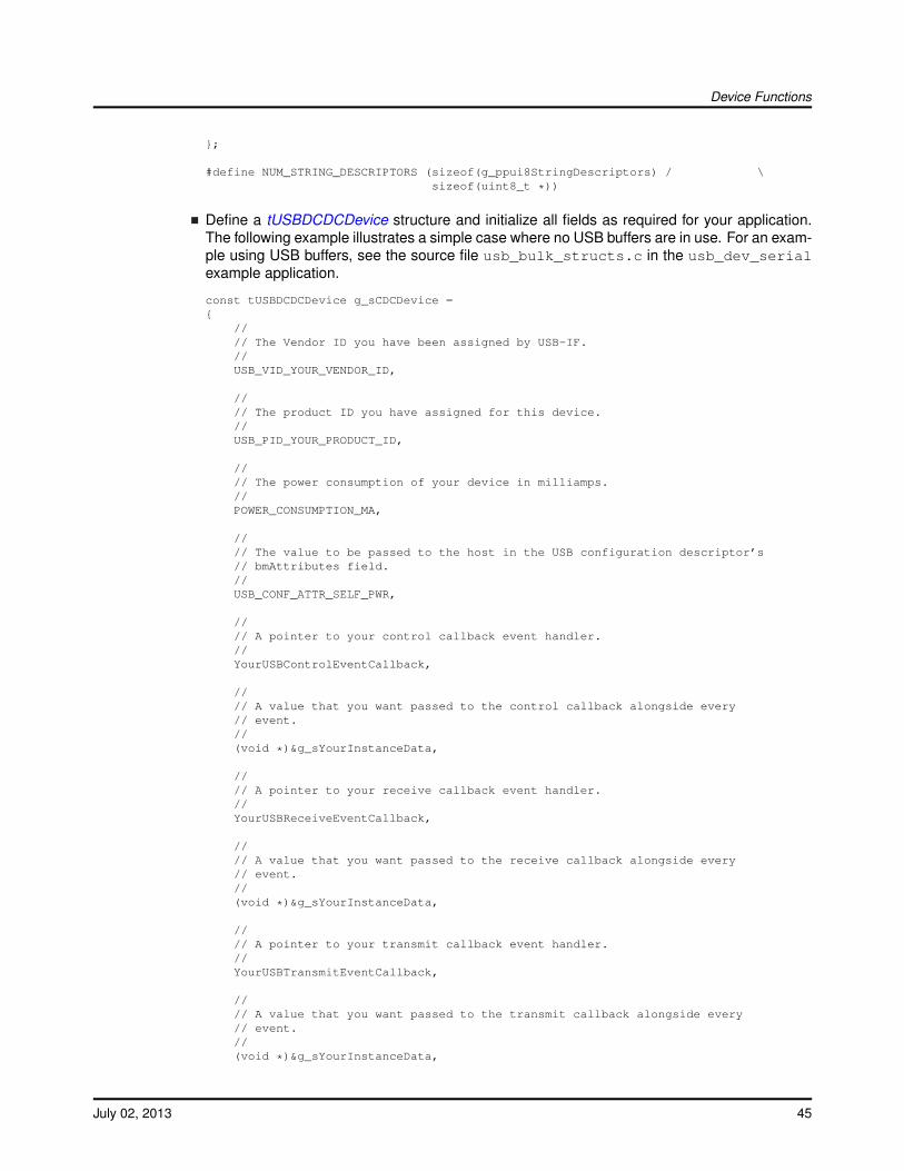
Device Functions
};
#define NUM_STRING_DESCRIPTORS (sizeof(g_ppui8StringDescriptors) / \sizeof(uint8_t *))
Define a tUSBDCDCDevice structure and initialize all fields as required for your application.The following example illustrates a simple case where no USB buffers are in use. For an exam-ple using USB buffers, see the source file usb_bulk_structs.c in the usb_dev_serialexample application.
const tUSBDCDCDevice g_sCDCDevice ={
//// The Vendor ID you have been assigned by USB-IF.//USB_VID_YOUR_VENDOR_ID,
//// The product ID you have assigned for this device.//USB_PID_YOUR_PRODUCT_ID,
//// The power consumption of your device in milliamps.//POWER_CONSUMPTION_MA,
//// The value to be passed to the host in the USB configuration descriptor’s// bmAttributes field.//USB_CONF_ATTR_SELF_PWR,
//// A pointer to your control callback event handler.//YourUSBControlEventCallback,
//// A value that you want passed to the control callback alongside every// event.//(void *)&g_sYourInstanceData,
//// A pointer to your receive callback event handler.//YourUSBReceiveEventCallback,
//// A value that you want passed to the receive callback alongside every// event.//(void *)&g_sYourInstanceData,
//// A pointer to your transmit callback event handler.//YourUSBTransmitEventCallback,
//// A value that you want passed to the transmit callback alongside every// event.//(void *)&g_sYourInstanceData,
July 02, 2013 45
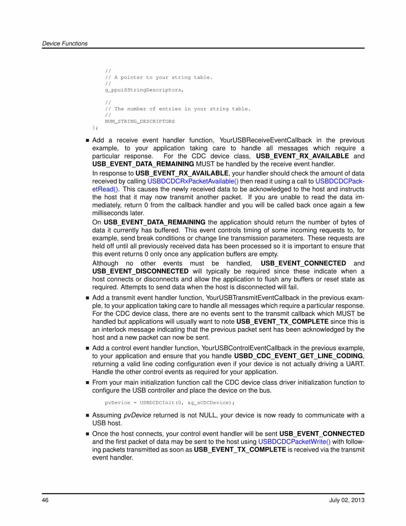
Device Functions
//// A pointer to your string table.//g_ppui8StringDescriptors,
//// The number of entries in your string table.//NUM_STRING_DESCRIPTORS
};
Add a receive event handler function, YourUSBReceiveEventCallback in the previousexample, to your application taking care to handle all messages which require aparticular response. For the CDC device class, USB_EVENT_RX_AVAILABLE andUSB_EVENT_DATA_REMAINING MUST be handled by the receive event handler.In response to USB_EVENT_RX_AVAILABLE, your handler should check the amount of datareceived by calling USBDCDCRxPacketAvailable() then read it using a call to USBDCDCPack-etRead(). This causes the newly received data to be acknowledged to the host and instructsthe host that it may now transmit another packet. If you are unable to read the data im-mediately, return 0 from the callback handler and you will be called back once again a fewmilliseconds later.On USB_EVENT_DATA_REMAINING the application should return the number of bytes ofdata it currently has buffered. This event controls timing of some incoming requests to, forexample, send break conditions or change line transmission parameters. These requests areheld off until all previously received data has been processed so it is important to ensure thatthis event returns 0 only once any application buffers are empty.Although no other events must be handled, USB_EVENT_CONNECTED andUSB_EVENT_DISCONNECTED will typically be required since these indicate when ahost connects or disconnects and allow the application to flush any buffers or reset state asrequired. Attempts to send data when the host is disconnected will fail.
Add a transmit event handler function, YourUSBTransmitEventCallback in the previous exam-ple, to your application taking care to handle all messages which require a particular response.For the CDC device class, there are no events sent to the transmit callback which MUST behandled but applications will usually want to note USB_EVENT_TX_COMPLETE since this isan interlock message indicating that the previous packet sent has been acknowledged by thehost and a new packet can now be sent.
Add a control event handler function, YourUSBControlEventCallback in the previous example,to your application and ensure that you handle USBD_CDC_EVENT_GET_LINE_CODING,returning a valid line coding configuration even if your device is not actually driving a UART.Handle the other control events as required for your application.
From your main initialization function call the CDC device class driver initialization function toconfigure the USB controller and place the device on the bus.
pvDevice = USBDCDCInit(0, &g_sCDCDevice);
Assuming pvDevice returned is not NULL, your device is now ready to communicate with aUSB host.
Once the host connects, your control event handler will be sent USB_EVENT_CONNECTEDand the first packet of data may be sent to the host using USBDCDCPacketWrite() with follow-ing packets transmitted as soon as USB_EVENT_TX_COMPLETE is received via the transmitevent handler.
46 July 02, 2013
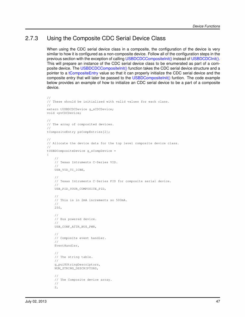
Device Functions
2.7.3 Using the Composite CDC Serial Device Class
When using the CDC serial device class in a composite, the configuration of the device is verysimilar to how it is configured as a non-composite device. Follow all of the configuration steps in theprevious section with the exception of calling USBDCDCCompositeInit() instead of USBDCDCInit().This will prepare an instance of the CDC serial device class to be enumerated as part of a com-posite device. The USBDCDCCompositeInit() function takes the CDC serial device structure and apointer to a tCompositeEntry value so that it can properly initialize the CDC serial device and thecomposite entry that will later be passed to the USBDCompositeInit() funtion. The code examplebelow provides an example of how to initialize an CDC serial device to be a part of a compositedevice.
//// These should be initialized with valid values for each class.//extern tUSBDCDCDevice g_sCDCDevice;void *pvCDCDevice;
//// The array of composited devices.//tCompositeEntry psCompEntries[2];
//// Allocate the device data for the top level composite device class.//tUSBDCompositeDevice g_sCompDevice ={
//// Texas Intruments C-Series VID.//USB_VID_TI_1CBE,
//// Texas Intruments C-Series PID for composite serial device.//USB_PID_YOUR_COMPOSITE_PID,
//// This is in 2mA increments so 500mA.//250,
//// Bus powered device.//USB_CONF_ATTR_BUS_PWR,
//// Composite event handler.//EventHandler,
//// The string table.//g_pui8StringDescriptors,NUM_STRING_DESCRIPTORS,
//// The Composite device array.//2,
July 02, 2013 47
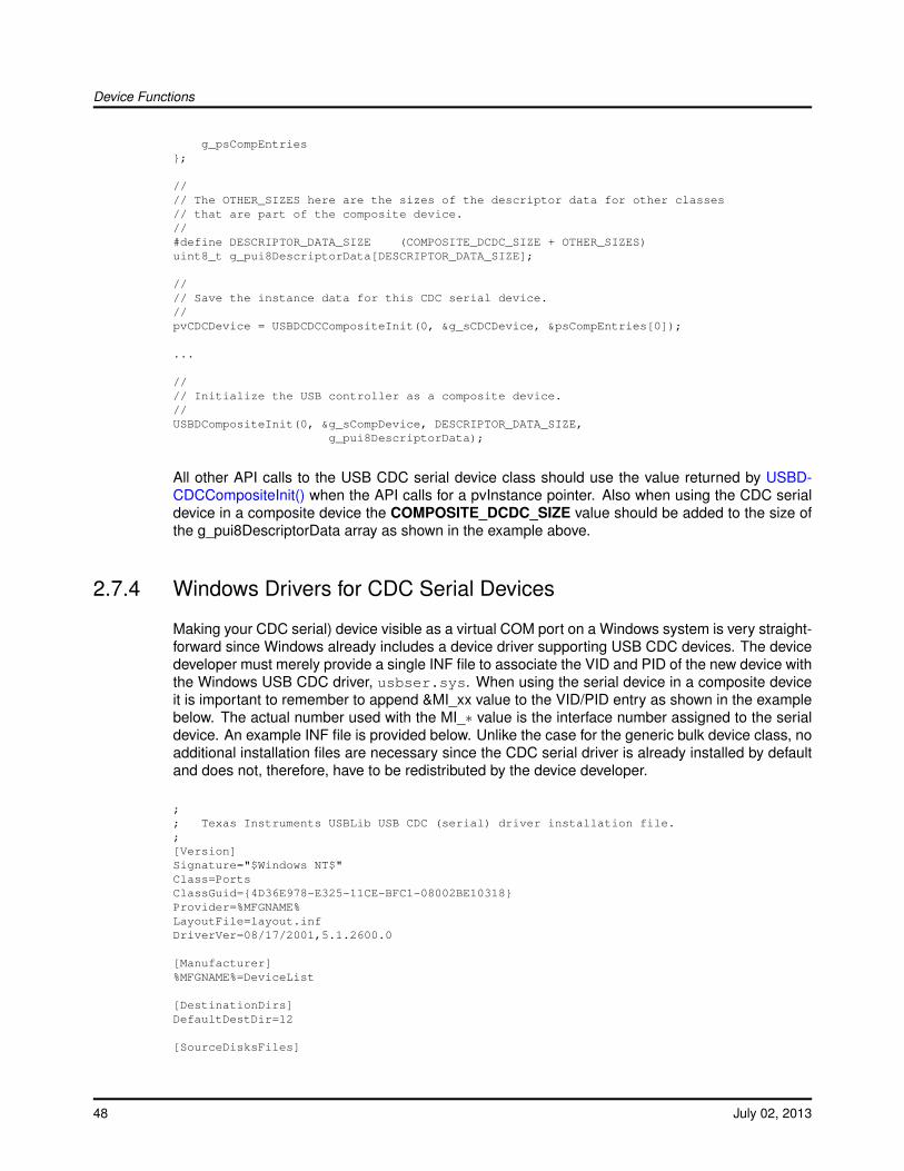
Device Functions
g_psCompEntries};
//// The OTHER_SIZES here are the sizes of the descriptor data for other classes// that are part of the composite device.//#define DESCRIPTOR_DATA_SIZE (COMPOSITE_DCDC_SIZE + OTHER_SIZES)uint8_t g_pui8DescriptorData[DESCRIPTOR_DATA_SIZE];
//// Save the instance data for this CDC serial device.//pvCDCDevice = USBDCDCCompositeInit(0, &g_sCDCDevice, &psCompEntries[0]);
...
//// Initialize the USB controller as a composite device.//USBDCompositeInit(0, &g_sCompDevice, DESCRIPTOR_DATA_SIZE,
g_pui8DescriptorData);
All other API calls to the USB CDC serial device class should use the value returned by USBD-CDCCompositeInit() when the API calls for a pvInstance pointer. Also when using the CDC serialdevice in a composite device the COMPOSITE_DCDC_SIZE value should be added to the size ofthe g_pui8DescriptorData array as shown in the example above.
2.7.4 Windows Drivers for CDC Serial Devices
Making your CDC serial) device visible as a virtual COM port on a Windows system is very straight-forward since Windows already includes a device driver supporting USB CDC devices. The devicedeveloper must merely provide a single INF file to associate the VID and PID of the new device withthe Windows USB CDC driver, usbser.sys. When using the serial device in a composite deviceit is important to remember to append &MI_xx value to the VID/PID entry as shown in the examplebelow. The actual number used with the MI_∗ value is the interface number assigned to the serialdevice. An example INF file is provided below. Unlike the case for the generic bulk device class, noadditional installation files are necessary since the CDC serial driver is already installed by defaultand does not, therefore, have to be redistributed by the device developer.
;; Texas Instruments USBLib USB CDC (serial) driver installation file.;[Version]Signature="$Windows NT$"Class=PortsClassGuid={4D36E978-E325-11CE-BFC1-08002BE10318}Provider=%MFGNAME%LayoutFile=layout.infDriverVer=08/17/2001,5.1.2600.0
[Manufacturer]%MFGNAME%=DeviceList
[DestinationDirs]DefaultDestDir=12
[SourceDisksFiles]
48 July 02, 2013
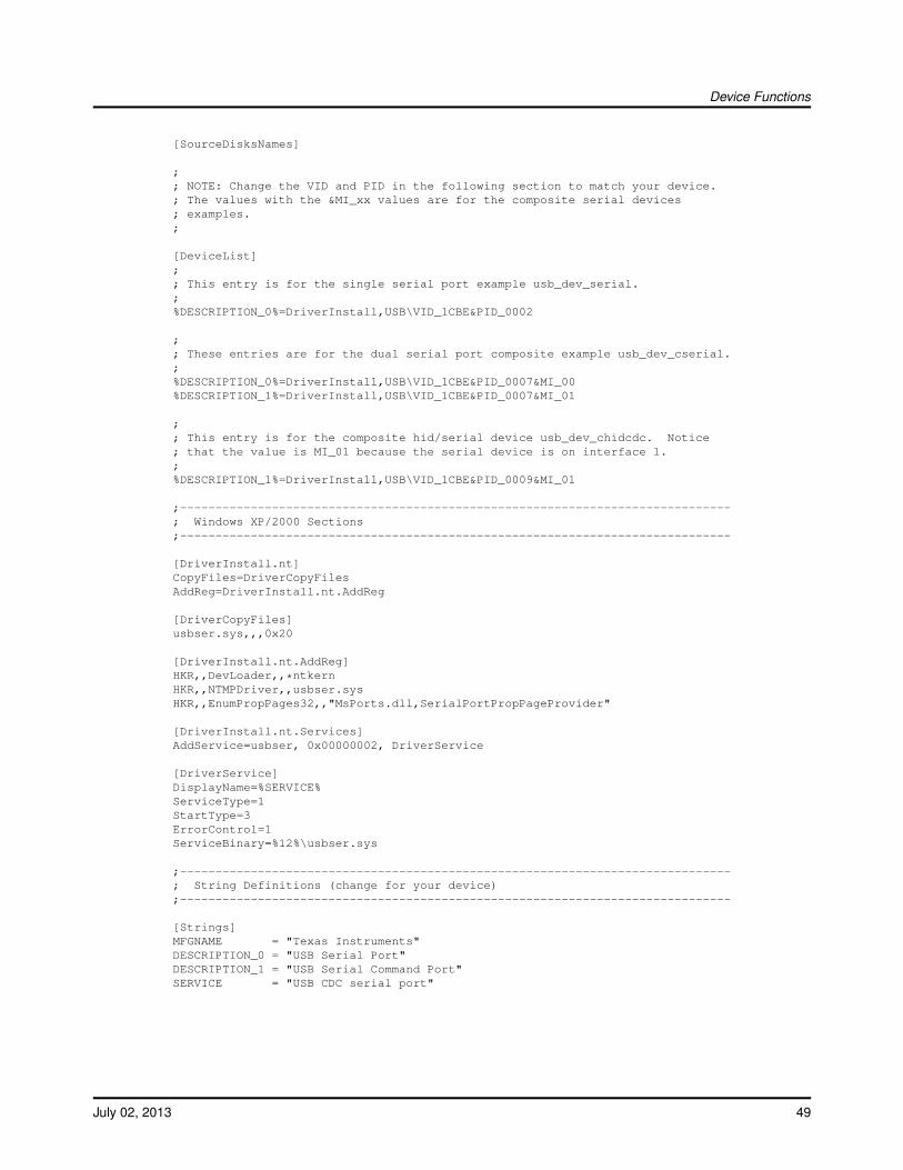
Device Functions
[SourceDisksNames]
;; NOTE: Change the VID and PID in the following section to match your device.; The values with the &MI_xx values are for the composite serial devices; examples.;
[DeviceList];; This entry is for the single serial port example usb_dev_serial.;%DESCRIPTION_0%=DriverInstall,USB\VID_1CBE&PID_0002
;; These entries are for the dual serial port composite example usb_dev_cserial.;%DESCRIPTION_0%=DriverInstall,USB\VID_1CBE&PID_0007&MI_00%DESCRIPTION_1%=DriverInstall,USB\VID_1CBE&PID_0007&MI_01
;; This entry is for the composite hid/serial device usb_dev_chidcdc. Notice; that the value is MI_01 because the serial device is on interface 1.;%DESCRIPTION_1%=DriverInstall,USB\VID_1CBE&PID_0009&MI_01
;------------------------------------------------------------------------------; Windows XP/2000 Sections;------------------------------------------------------------------------------
[DriverInstall.nt]CopyFiles=DriverCopyFilesAddReg=DriverInstall.nt.AddReg
[DriverCopyFiles]usbser.sys,,,0x20
[DriverInstall.nt.AddReg]HKR,,DevLoader,,*ntkernHKR,,NTMPDriver,,usbser.sysHKR,,EnumPropPages32,,"MsPorts.dll,SerialPortPropPageProvider"
[DriverInstall.nt.Services]AddService=usbser, 0x00000002, DriverService
[DriverService]DisplayName=%SERVICE%ServiceType=1StartType=3ErrorControl=1ServiceBinary=%12%\usbser.sys
;------------------------------------------------------------------------------; String Definitions (change for your device);------------------------------------------------------------------------------
[Strings]MFGNAME = "Texas Instruments"DESCRIPTION_0 = "USB Serial Port"DESCRIPTION_1 = "USB Serial Command Port"SERVICE = "USB CDC serial port"
July 02, 2013 49
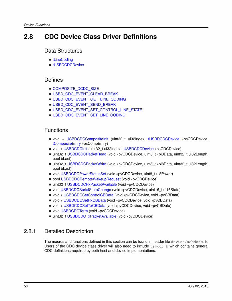
Device Functions
2.8 CDC Device Class Driver Definitions
Data StructurestLineCodingtUSBDCDCDevice
DefinesCOMPOSITE_DCDC_SIZEUSBD_CDC_EVENT_CLEAR_BREAKUSBD_CDC_EVENT_GET_LINE_CODINGUSBD_CDC_EVENT_SEND_BREAKUSBD_CDC_EVENT_SET_CONTROL_LINE_STATEUSBD_CDC_EVENT_SET_LINE_CODING
Functionsvoid ∗ USBDCDCCompositeInit (uint32_t ui32Index, tUSBDCDCDevice ∗psCDCDevice,tCompositeEntry ∗psCompEntry)void ∗ USBDCDCInit (uint32_t ui32Index, tUSBDCDCDevice ∗psCDCDevice)uint32_t USBDCDCPacketRead (void ∗pvCDCDevice, uint8_t ∗pi8Data, uint32_t ui32Length,bool bLast)uint32_t USBDCDCPacketWrite (void ∗pvCDCDevice, uint8_t ∗pi8Data, uint32_t ui32Length,bool bLast)void USBDCDCPowerStatusSet (void ∗pvCDCDevice, uint8_t ui8Power)bool USBDCDCRemoteWakeupRequest (void ∗pvCDCDevice)uint32_t USBDCDCRxPacketAvailable (void ∗pvCDCDevice)void USBDCDCSerialStateChange (void ∗pvCDCDevice, uint16_t ui16State)void ∗ USBDCDCSetControlCBData (void ∗pvCDCDevice, void ∗pvCBData)void ∗ USBDCDCSetRxCBData (void ∗pvCDCDevice, void ∗pvCBData)void ∗ USBDCDCSetTxCBData (void ∗pvCDCDevice, void ∗pvCBData)void USBDCDCTerm (void ∗pvCDCDevice)uint32_t USBDCDCTxPacketAvailable (void ∗pvCDCDevice)
2.8.1 Detailed Description
The macros and functions defined in this section can be found in header file device/usbdcdc.h.Users of the CDC device class driver will also need to include usbcdc.h which contains generalCDC definitions required by both host and device implementations.
50 July 02, 2013
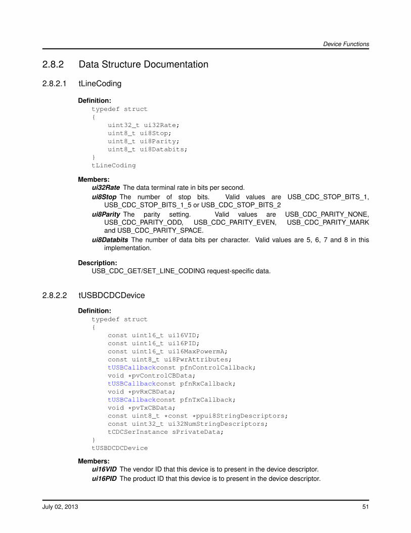
Device Functions
2.8.2 Data Structure Documentation
2.8.2.1 tLineCoding
Definition:typedef struct{
uint32_t ui32Rate;uint8_t ui8Stop;uint8_t ui8Parity;uint8_t ui8Databits;
}tLineCoding
Members:ui32Rate The data terminal rate in bits per second.ui8Stop The number of stop bits. Valid values are USB_CDC_STOP_BITS_1,
USB_CDC_STOP_BITS_1_5 or USB_CDC_STOP_BITS_2ui8Parity The parity setting. Valid values are USB_CDC_PARITY_NONE,
USB_CDC_PARITY_ODD, USB_CDC_PARITY_EVEN, USB_CDC_PARITY_MARKand USB_CDC_PARITY_SPACE.
ui8Databits The number of data bits per character. Valid values are 5, 6, 7 and 8 in thisimplementation.
Description:USB_CDC_GET/SET_LINE_CODING request-specific data.
2.8.2.2 tUSBDCDCDevice
Definition:typedef struct{
const uint16_t ui16VID;const uint16_t ui16PID;const uint16_t ui16MaxPowermA;const uint8_t ui8PwrAttributes;tUSBCallbackconst pfnControlCallback;void *pvControlCBData;tUSBCallbackconst pfnRxCallback;void *pvRxCBData;tUSBCallbackconst pfnTxCallback;void *pvTxCBData;const uint8_t *const *ppui8StringDescriptors;const uint32_t ui32NumStringDescriptors;tCDCSerInstance sPrivateData;
}tUSBDCDCDevice
Members:ui16VID The vendor ID that this device is to present in the device descriptor.ui16PID The product ID that this device is to present in the device descriptor.
July 02, 2013 51
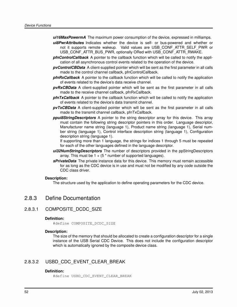
Device Functions
ui16MaxPowermA The maximum power consumption of the device, expressed in milliamps.ui8PwrAttributes Indicates whether the device is self- or bus-powered and whether or
not it supports remote wakeup. Valid values are USB_CONF_ATTR_SELF_PWR orUSB_CONF_ATTR_BUS_PWR, optionally ORed with USB_CONF_ATTR_RWAKE.
pfnControlCallback A pointer to the callback function which will be called to notify the appli-cation of all asynchronous control events related to the operation of the device.
pvControlCBData A client-supplied pointer which will be sent as the first parameter in all callsmade to the control channel callback, pfnControlCallback.
pfnRxCallback A pointer to the callback function which will be called to notify the applicationof events related to the device’s data receive channel.
pvRxCBData A client-supplied pointer which will be sent as the first parameter in all callsmade to the receive channel callback, pfnRxCallback.
pfnTxCallback A pointer to the callback function which will be called to notify the applicationof events related to the device’s data transmit channel.
pvTxCBData A client-supplied pointer which will be sent as the first parameter in all callsmade to the transmit channel callback, pfnTxCallback.
ppui8StringDescriptors A pointer to the string descriptor array for this device. This arraymust contain the following string descriptor pointers in this order. Language descriptor,Manufacturer name string (language 1), Product name string (language 1), Serial num-ber string (language 1), Control interface description string (language 1), Configurationdescription string (language 1).If supporting more than 1 language, the strings for indices 1 through 5 must be repeatedfor each of the other languages defined in the language descriptor.
ui32NumStringDescriptors The number of descriptors provided in the ppStringDescriptorsarray. This must be 1 + (5 * number of supported languages).
sPrivateData The private instance data for this device. This memory must remain accessiblefor as long as the CDC device is in use and must not be modified by any code outside theCDC class driver.
Description:The structure used by the application to define operating parameters for the CDC device.
2.8.3 Define Documentation
2.8.3.1 COMPOSITE_DCDC_SIZE
Definition:#define COMPOSITE_DCDC_SIZE
Description:The size of the memory that should be allocated to create a configuration descriptor for a singleinstance of the USB Serial CDC Device. This does not include the configuration descriptorwhich is automatically ignored by the composite device class.
2.8.3.2 USBD_CDC_EVENT_CLEAR_BREAK
Definition:#define USBD_CDC_EVENT_CLEAR_BREAK
52 July 02, 2013
Device Functions
Description:The host requests that the device stop sending a BREAK condition on its serial communicationchannel.
2.8.3.3 USBD_CDC_EVENT_GET_LINE_CODING
Definition:#define USBD_CDC_EVENT_GET_LINE_CODING
Description:The host is querying the current RS232 communication parameters. The pvMsgData parame-ter points to a tLineCoding structure that the application must fill with the current settings priorto returning from the callback.
2.8.3.4 USBD_CDC_EVENT_SEND_BREAK
Definition:#define USBD_CDC_EVENT_SEND_BREAK
Description:The host requests that the device send a BREAK condition on its serial communication chan-nel. The BREAK should remain active until a USBD_CDC_EVENT_CLEAR_BREAK event isreceived.
2.8.3.5 USBD_CDC_EVENT_SET_CONTROL_LINE_STATE
Definition:#define USBD_CDC_EVENT_SET_CONTROL_LINE_STATE
Description:The host requests that the device set the RS232 signaling lines to a particular state. Theui32MsgValue parameter contains the RTS and DTR control line states as defined in table 51of the USB CDC class definition and is a combination of the following values:
(RTS) USB_CDC_DEACTIVATE_CARRIER or USB_CDC_ACTIVATE_CARRIER (DTR)USB_CDC_DTE_NOT_PRESENT or USB_CDC_DTE_PRESENT
2.8.3.6 USBD_CDC_EVENT_SET_LINE_CODING
Definition:#define USBD_CDC_EVENT_SET_LINE_CODING
Description:The host requests that the device set the RS232 communication parameters. The pvMsgDataparameter points to a tLineCoding structure defining the required number of bits per character,parity mode, number of stop bits and the baud rate.
July 02, 2013 53
Device Functions
2.8.4 Function Documentation
2.8.4.1 USBDCDCCompositeInit
Initializes CDC device operation when used with a composite device.
Prototype:void *USBDCDCCompositeInit(uint32_t ui32Index,
tUSBDCDCDevice *psCDCDevice,tCompositeEntry *psCompEntry)
Parameters:ui32Index is the index of the USB controller in use.psCDCDevice points to a structure containing parameters customizing the operation of the
CDC device.psCompEntry is the composite device entry to initialize when creating a composite device.
Description:This call is very similar to USBDCDCInit() except that it is used for initializing an instance of theserial device for use in a composite device. When this CDC serial device is part of a compositedevice, then the psCompEntry should point to the composite device entry to initialize. This ispart of the array that is passed to the USBDCompositeInit() function.
Returns:Returns zero on failure or a non-zero instance value that should be used with the remainingUSB CDC APIs.
2.8.4.2 USBDCDCInit
Initializes CDC device operation for a given USB controller.
Prototype:void *USBDCDCInit(uint32_t ui32Index,
tUSBDCDCDevice *psCDCDevice)
Parameters:ui32Index is the index of the USB controller which is to be initialized for CDC device operation.psCDCDevice points to a structure containing parameters customizing the operation of the
CDC device.
Description:An application wishing to make use of a USB CDC communication channel and appear as avirtual serial port on the host system must call this function to initialize the USB controller andattach the device to the USB bus. This function performs all required USB initialization.
The value returned by this function is the psCDCDevice pointer passed to it if successful. Thispointer must be passed to all later calls to the CDC class driver to identify the device instance.
The USB CDC device class driver offers packet-based transmit and receive operation. If theapplication would rather use block based communication with transmit and receive buffers,USB buffers on the transmit and receive channels may be used to offer this functionality.
54 July 02, 2013
Device Functions
Transmit Operation:
Calls to USBDCDCPacketWrite() must send no more than 64 bytes of data at a time and mayonly be made when no other transmission is currently outstanding.
Once a packet of data has been acknowledged by the USB host, aUSB_EVENT_TX_COMPLETE event is sent to the application callback to inform it thatanother packet may be transmitted.
Receive Operation:
An incoming USB data packet will result in a call to the application callback with eventUSB_EVENT_RX_AVAILABLE. The application must then call USBDCDCPacketRead(),passing a buffer capable of holding the received packet to retrieve the data and acknowl-edge reception to the USB host. The size of the received packet may be queried by callingUSBDCDCRxPacketAvailable().
Note:The application must not make any calls to the low level USB Device API if interacting withUSB via the CDC device class API. Doing so will cause unpredictable (though almost certainlyunpleasant) behavior.
Returns:Returns NULL on failure or the psCDCDevice pointer on success.
2.8.4.3 USBDCDCPacketRead
Reads a packet of data received from the USB host via the CDC data interface.
Prototype:uint32_tUSBDCDCPacketRead(void *pvCDCDevice,
uint8_t *pi8Data,uint32_t ui32Length,bool bLast)
Parameters:pvCDCDevice is the pointer to the device instance structure as returned by USBDCDCInit().pi8Data points to a buffer into which the received data will be written.ui32Length is the size of the buffer pointed to by pi8Data.bLast indicates whether the client will make a further call to read additional data from the
packet.
Description:This function reads up to ui32Length bytes of data received from the USB host into the suppliedapplication buffer.
Note:The bLast parameter is ignored in this implementation since the end of a packet can be deter-mined without relying upon the client to provide this information.
Returns:Returns the number of bytes of data read.
July 02, 2013 55
Device Functions
2.8.4.4 USBDCDCPacketWrite
Transmits a packet of data to the USB host via the CDC data interface.
Prototype:uint32_tUSBDCDCPacketWrite(void *pvCDCDevice,
uint8_t *pi8Data,uint32_t ui32Length,bool bLast)
Parameters:pvCDCDevice is the pointer to the device instance structure as returned by USBDCDCInit().pi8Data points to the first byte of data which is to be transmitted.ui32Length is the number of bytes of data to transmit.bLast indicates whether more data is to be written before a packet should be scheduled for
transmission. If true, the client will make a further call to this function. If false, no furthercall will be made and the driver should schedule transmission of a short packet.
Description:This function schedules the supplied data for transmission to the USB host in a singleUSB packet. If no transmission is currently ongoing the data is immediately copied to therelevant USB endpoint FIFO. If the bLast parameter is true, the newly written packet isthen scheduled for transmission. Whenever a USB packet is acknowledged by the host, aUSB_EVENT_TX_COMPLETE event will be sent to the application transmit callback indicat-ing that more data can now be transmitted.
The maximum value for ui32Length is 64 bytes (the maximum USB packet size for the bulkendpoints in use by CDC). Attempts to send more data than this will result in a return code of0 indicating that the data cannot be sent.
Returns:Returns the number of bytes actually sent. At this level, this will either be the number of bytespassed (if less than or equal to the maximum packet size for the USB endpoint in use and nooutstanding transmission ongoing) or 0 to indicate a failure.
2.8.4.5 USBDCDCPowerStatusSet
Reports the device power status (bus- or self-powered) to the USB library.
Prototype:voidUSBDCDCPowerStatusSet(void *pvCDCDevice,
uint8_t ui8Power)
Parameters:pvCDCDevice is the pointer to the CDC device instance structure.ui8Power indicates the current power status, either USB_STATUS_SELF_PWR or
USB_STATUS_BUS_PWR.
Description:Applications which support switching between bus- or self-powered operation should call thisfunction whenever the power source changes to indicate the current power status to the USB
56 July 02, 2013
Device Functions
library. This information is required by the USB library to allow correct responses to be providedwhen the host requests status from the device.
Returns:None.
2.8.4.6 USBDCDCRemoteWakeupRequest
Requests a remote wakeup to resume communication when in suspended state.
Prototype:boolUSBDCDCRemoteWakeupRequest(void *pvCDCDevice)
Parameters:pvCDCDevice is the pointer to the CDC device instance structure.
Description:When the bus is suspended, an application which supports remote wakeup (advertised to thehost via the configuration descriptor) may call this function to initiate remote wakeup signalingto the host. If the remote wakeup feature has not been disabled by the host, this will cause thebus to resume operation within 20mS. If the host has disabled remote wakeup, false will bereturned to indicate that the wakeup request was not successful.
Returns:Returns true if the remote wakeup is not disabled and the signaling was started or false ifremote wakeup is disabled or if signaling is currently ongoing following a previous call to thisfunction.
2.8.4.7 USBDCDCRxPacketAvailable
Determines whether a packet is available and, if so, the size of the buffer required to read it.
Prototype:uint32_tUSBDCDCRxPacketAvailable(void *pvCDCDevice)
Parameters:pvCDCDevice is the pointer to the device instance structure as returned by USBDCDCInit().
Description:This function may be used to determine if a received packet remains to be read and allows theapplication to determine the buffer size needed to read the data.
Returns:Returns 0 if no received packet remains unprocessed or the size of the packet if a packet iswaiting to be read.
July 02, 2013 57
Device Functions
2.8.4.8 USBDCDCSerialStateChange
Informs the CDC module of changes in the serial control line states or receive error conditions.
Prototype:voidUSBDCDCSerialStateChange(void *pvCDCDevice,
uint16_t ui16State)
Parameters:pvCDCDevice is the pointer to the device instance structure as returned by USBDCDCInit().ui16State indicates the states of the various control lines and any receive errors detected. Bit
definitions are as for the USB CDC SerialState asynchronous notification and are definedin header file usbcdc.h.
Description:The application should call this function whenever the state of any of the incoming RS232handshake signals changes or in response to a receive error or break condition. The ui16Stateparameter is the ORed combination of the following flags with each flag indicating the presenceof that condition.
USB_CDC_SERIAL_STATE_OVERRUNUSB_CDC_SERIAL_STATE_PARITYUSB_CDC_SERIAL_STATE_FRAMINGUSB_CDC_SERIAL_STATE_RING_SIGNALUSB_CDC_SERIAL_STATE_BREAKUSB_CDC_SERIAL_STATE_TXCARRIERUSB_CDC_SERIAL_STATE_RXCARRIER
This function should be called only when the state of any flag changes.
Returns:None.
2.8.4.9 USBDCDCSetControlCBData
Sets the client-specific pointer for the control callback.
Prototype:void *USBDCDCSetControlCBData(void *pvCDCDevice,
void *pvCBData)
Parameters:pvCDCDevice is the pointer to the device instance structure as returned by USBDCDCInit().pvCBData is the pointer that client wishes to be provided on each event sent to the control
channel callback function.
Description:The client uses this function to change the callback pointer passed in the first parameter on allcallbacks to the pfnControlCallback function passed on USBDCDCInit().
58 July 02, 2013
Device Functions
If a client wants to make runtime changes in the callback pointer, it must ensure that the psCD-CDevice structure passed to USBDCDCInit() resides in RAM. If this structure is in flash, call-back pointer changes will not be possible.
Returns:Returns the previous callback pointer that was being used for this instance’s control callback.
2.8.4.10 USBDCDCSetRxCBData
Sets the client-specific data parameter for the receive channel callback.
Prototype:void *USBDCDCSetRxCBData(void *pvCDCDevice,
void *pvCBData)
Parameters:pvCDCDevice is the pointer to the device instance structure as returned by USBDCDCInit().pvCBData is the pointer that client wishes to be provided on each event sent to the receive
channel callback function.
Description:The client uses this function to change the callback pointer passed in the first parameter on allcallbacks to the pfnRxCallback function passed on USBDCDCInit().
If a client wants to make runtime changes in the callback pointer, it must ensure that the psCD-CDevice structure passed to USBDCDCInit() resides in RAM. If this structure is in flash, call-back data changes will not be possible.
Returns:Returns the previous callback pointer that was being used for this instance’s receive callback.
2.8.4.11 USBDCDCSetTxCBData
Sets the client-specific data parameter for the transmit callback.
Prototype:void *USBDCDCSetTxCBData(void *pvCDCDevice,
void *pvCBData)
Parameters:pvCDCDevice is the pointer to the device instance structure as returned by USBDCDCInit().pvCBData is the pointer that client wishes to be provided on each event sent to the transmit
channel callback function.
Description:The client uses this function to change the callback pointer passed in the first parameter on allcallbacks to the pfnTxCallback function passed on USBDCDCInit().
If a client wants to make runtime changes in the callback pointer, it must ensure that the psCD-CDevice structure passed to USBDCDCInit() resides in RAM. If this structure is in flash, call-back data changes will not be possible.
July 02, 2013 59
Device Functions
Returns:Returns the previous callback pointer that was being used for this instance’s transmit callback.
2.8.4.12 USBDCDCTerm
Shuts down the CDC device instance.
Prototype:voidUSBDCDCTerm(void *pvCDCDevice)
Parameters:pvCDCDevice is the pointer to the device instance structure as returned by USBDCDCInit().
Description:This function terminates CDC operation for the instance supplied and removes the device fromthe USB bus. This function should not be called if the CDC device is part of a composite deviceand instead the USBDCompositeTerm() function should be called for the full composite device.
Following this call, the pvCDCDevice instance should not me used in any other calls.
Returns:None.
2.8.4.13 USBDCDCTxPacketAvailable
Returns the number of free bytes in the transmit buffer.
Prototype:uint32_tUSBDCDCTxPacketAvailable(void *pvCDCDevice)
Parameters:pvCDCDevice is the pointer to the device instance structure as returned by USBDCDCInit().
Description:This function returns the maximum number of bytes that can be passed on a call to USBDCD-CPacketWrite() and accepted for transmission. The value returned will be the maximum USBpacket size if no transmission is currently outstanding or 0 if a transmission is in progress.
Returns:Returns the number of bytes available in the transmit buffer.
2.9 Composite Device Class Driver
The USB composite device class allows classes that are already defined in the USB library to becombined into a single composite device. The device configuration descriptors for the includeddevice classes are merged at run time and returned to the USB host controller during deviceenumeration as a single composite USB device. Since each device class requires some unique
60 July 02, 2013

Device Functions
initialization, the device classes provide a separate initialization API that does not touch the USBcontroller but does perform all other initialization. The initialization of the USB controller is deferreduntil the USB composite device is initialized and has merged the multiple device configuration de-scriptors into a single configuration descriptor so that it can properly initialize the USB controller.The endpoint numbers, interface numbers, and string indexes that are included in the device con-figuration descriptors are modified by the USB composite device class so that the values are validin the composite device configuration descriptor.
2.9.1 Defining a Composite Device
The USB composite device class is defined at the top level in the tUSBDCompositeDevice struc-ture which is used to describe the class to the USB library. In order for the USB composite deviceto enumerate and function properly, all members of this structure must be filled with valid infor-mation. The usVID and usPID values should have valid Vendor ID and Product ID values for thecomposite device. The power requirements for the device as specified in the usMaxPowermA anducPwrAttributes and should take into account the power requirements and settings for all devicesclasses that the composite device is using. The only truly optional member of the tUSBDCompos-iteDevice structure is the pfnCallback function which provides notifications to the application thatare not handled by the individual device classes. The device specific strings should be includedin the ppui8StringDescriptors and ui32NumStringDescriptors members. This list of strings shouldinclude the following three strings in the following order: Manufacturer, Product, and Product serialnumber. All other strings used by the classes are specified and are sourced from the includeddevice classes. The psPrivateData should be set to point to a tCompositeInstance structure whichprovides the composite class with memory for its instance data.
Note: It is important to insure that the microcontroller has enough endpoints to satisfy the numberof devices included in the composite class.
Example:
uint32_t g_pui32CompWorkspace[NUM_DEVICES];
tUSBDCompositeDevice g_sCompDevice ={
//// Vendor ID.//VENDOR_ID,
//// Product ID.//VENDOR_PRODUCT_ID,
//// This is in 2mA increments or 500mA.//250,
//// Bus powered device.//USB_CONF_ATTR_BUS_PWR,
//// Generic USB handler for the composite device.//CompositeHandler,
July 02, 2013 61
Device Functions
//// The string table.//g_pStringDescriptors,NUM_STRING_DESCRIPTORS,
//// The number of device classes in the composite entry array.//NUM_DEVICES,g_psCompDevices
};
2.9.2 Allocating Memory
The USB composite device class requires three different types of memory allocated to properlyenumerate and function with the included device classes. The main allocation is a block of memorythat is used to build up the combined device configuration descriptor for the combination of thedesired device classes. The individual device classes will provide a size in a COMPOSITE_∗_SIZEmacro that indicates the size in bytes required to hold the configuration descriptor for the deviceclass. This allows the application to provide a large enough buffer to the USBDCompositeInit()function for merging the device descriptors.
2.9.2.1 Defining Device Class Instances
When defining a composite device the application must determine the size of the buffer that ispassed into the USBDCompositeInit() function. For example, if a composite device is made up oftwo serial devices then a buffer of size (COMPOSITE_DCDC_SIZE ∗ 2) should be passed into theinitialization routine and an array of that size should be declared in the application.
uint8_t pucDesciptorData[COMPOSITE_DCDC_SIZE*2];
The application must also allocate separate serial device structure for each instance of the devicesthat are included in a composite device. This is true even when including two devices classes ofthe same type are added so that the instances can be differentiated by the USB library. The USBcomposite device class can determine which instance to use based on the interface number that isaccessed by the host controller. The application initializes the data in the array of tCompositeEntrystructures passed into the composite initialization for the class.
Example: Two serial instances and the composite device array.
extern tUSBDCDCDevice g_sCDCDeviceA;extern tUSBDCDCDevice g_sCDCDeviceB;
tCompositeEntry g_psDevices[2];
2.9.2.2 Interface Handling
The device class interfaces will be merged into the composite device descriptor and the compositeclass modifies the default interface assignments to insure monotonically increasing indexes for allof the included interfaces. In the example above for the two serial ports, the first serial device wouldbe interface 0 and the second would enumerate as interface 1.
62 July 02, 2013
Device Functions
2.9.2.3 String Handling
The device class strings will be merged into the composite device descriptor which will require thatthe composite class modify the default string indexes. In doing this it will always ignore the threedefault string indexes in the device descriptor. The remaining string indexes will be modified tomatch in the configuration descriptor.
2.9.3 Example Composite Device
This section will continue with the example above that used two USB device serial classes in asingle device. This will include more detailed examples and code that demonstrate the configurationand setup needed for a composite serial device.
2.9.3.1 Composite Device Instance
The application must first allocate two serial device structures and pass them into the compositeinitialization function for the USB serial CDC device. The allocation and initialization are shownbelow:
//// Buffers for serial device A.//const tUSBBuffer g_sTxBufferA;const tUSBBuffer g_sRxBufferA;
//// Buffers for serial device B.//const tUSBBuffer g_sTxBufferB;const tUSBBuffer g_sRxBufferB;
//// Device description for Serial Device A.//const tUSBDCDCDevice g_sCDCDeviceA ={
USB_VID_TI_1CBE,USB_PID_SERIAL,0,USB_CONF_ATTR_SELF_PWR,ControlHandler,(void *)&g_sCDCDeviceA,USBBufferEventCallback,(void *)&g_sRxBufferA,USBBufferEventCallback,(void *)&g_sTxBufferA,0,0
};
//// Device description for Serial Device B.//const tUSBDCDCDevice g_sCDCDeviceB ={
USB_VID_TI_1CBE,USB_PID_SERIAL,
July 02, 2013 63
Device Functions
0,USB_CONF_ATTR_SELF_PWR,ControlHandler,(void *)&g_sCDCDeviceB,USBBufferEventCallback,(void *)&g_sRxBufferB,USBBufferEventCallback,(void *)&g_sTxBufferB,0,0
};
Now the application must allocate the device array so that it is provided to the USB compositedevice class. The following code shows the allocation of the composite device array that holds thedata for the two serial devices.
tCompositeEntry g_psDevices[2];
Once the array of devices has been allocated, this array is included in the USB composite de-vice structure when the device structure is allocated and initialized. The code below shows thisallocation:
//// Initialize the USB composite device structure.//tUSBDCompositeDevice g_sCompDevice ={
//// TI USBLib VID.//USB_VID_TI_1CBE,
//// PID for the composite serial device.//USB_PID_COMP_SERIAL,
//// This is in 2mA increments so 500mA.//250,
//// Bus powered device.//USB_CONF_ATTR_BUS_PWR,
//// Generic USB handler for the composite device.//CompositeHandler,
//// The string table.//g_pStringDescriptors,NUM_STRING_DESCRIPTORS,
//// Include the array of composite devices.//NUM_DEVICES,
64 July 02, 2013
Device Functions
g_psCompDevices};
The last bit of memory that needs to be allocated is the USB composite device descriptor workspacewhich is provided at Initialization time. The allocation for two serial devices is shown below:
uint8_t pucDesciptorData[COMPOSITE_DCDC_SIZE*2];
Once all of the memory has been initialized and the appropriate memory allocated, the applicationmust call the initialization functions for each device instance. In the case of the serial ports, theUSB buffers used must also first be initialized before completing initialization.
//// Initialize the transmit and receive buffers.//USBBufferInit((tUSBBuffer *)&g_sTxBufferA);USBBufferInit((tUSBBuffer *)&g_sRxBufferA);USBBufferInit((tUSBBuffer *)&g_sTxBufferB);USBBufferInit((tUSBBuffer *)&g_sRxBufferB);
//// Initialize the two serial port instances that are part of this composite// device.//pvSerialDeviceA =
USBDCDCCompositeInit(0, &g_sCDCDeviceA, &g_psCompDevices[0]);pvSerialDeviceB =
USBDCDCCompositeInit(0, &g_sCDCDeviceB, &g_psCompDevices[1]);
//// Pass the device information to the USB library and place the device// on the bus.//USBDCompositeInit(0, &g_sCompDevice, COMPOSITE_DCDC_SIZE*2,
pucDesciptorData);
When calling the USB device classes that are included with a composite device, the instance datafor that class should be passed into the API. In the composite serial example that is being de-scribed in this section, the USB serial device classes provide the same callback function, Control-Handler(). The callback information for this was the device class structure which was specified asg_sCDCDeviceA or g_sCDCDeviceB for the serial devices. Since the device instance is different foreach serial device, the application can simply cast the pointer to a pointer of type tUSBDCDCDeviceand use the data directly as shown below and only access the requested device:
uint32_tControlHandler(void *pvCBData, uint32_t ui32Event,
uint32_t ui32MsgValue, void *pvMsgData){
tUSBDCDCDevice pCDCDevice;
pCDCDevice = (tUSBDCDCDevice *)pvCBData;
//// Which event are we being asked to process?//switch(ui32Event){
...}
}
July 02, 2013 65
Device Functions
2.10 Composite Device Class Driver Definitions
Data StructurestUSBDCompositeDevice
Functionsvoid ∗ USBDCompositeInit (uint32_t ui32Index, tUSBDCompositeDevice ∗psDevice, uint32_tui32Size, uint8_t ∗pui8Data)void USBDCompositeTerm (void ∗pvCompositeInstance)
2.10.1 Detailed Description
Definitions The macros and functions defined in this section can be found in header filedevice/usbdcomp.h.
2.10.2 Data Structure Documentation
2.10.2.1 tUSBDCompositeDevice
Definition:typedef struct{
const uint16_t ui16VID;const uint16_t ui16PID;const uint16_t ui16MaxPowermA;const uint8_t ui8PwrAttributes;tUSBCallbackconst pfnCallback;const uint8_t *const *ppui8StringDescriptors;const uint32_t ui32NumStringDescriptors;const uint32_t ui32NumDevices;tCompositeEntry *const psDevices;tCompositeInstance sPrivateData;
}tUSBDCompositeDevice
Members:ui16VID The vendor ID that this device is to present in the device descriptor.ui16PID The product ID that this device is to present in the device descriptor.ui16MaxPowermA The maximum power consumption of the device, expressed in mA.ui8PwrAttributes Indicates whether the device is self or bus-powered and whether or
not it supports remote wake up. Valid values are USB_CONF_ATTR_SELF_PWR orUSB_CONF_ATTR_BUS_PWR, optionally ORed with USB_CONF_ATTR_RWAKE.
pfnCallback A pointer to the callback function which will be called to notify the application ofevents relating to the operation of the composite device.
66 July 02, 2013
Device Functions
ppui8StringDescriptors A pointer to the string descriptor array for this device. This arraymust contain the following string descriptor pointers in this order. Language descriptor,Manufacturer name string (language 1), Product name string (language 1), Serial numberstring (language 1), Composite device interface description string (language 1), Configu-ration description string (language 1).If supporting more than 1 language, the descriptor block (except for string descriptor 0)must be repeated for each language defined in the language descriptor.
ui32NumStringDescriptors The number of descriptors provided in the ppStringDescriptorsarray. This must be 1 + ((5 + (number of strings)) * (number of languages)).
ui32NumDevices The number of devices in the psDevices array.psDevices This application supplied array holds the the top level device class information as
well as the Instance data for that class.sPrivateData The private data for this device instance. This memory must remain accessible
for as long as the composite device is in use and must not be modified by any code outsidethe composite class driver.
Description:The structure used by the application to define operating parameters for the composite deviceclass.
2.10.3 Function Documentation
2.10.3.1 USBDCompositeInit
This function should be called once for the composite class device to initialize basic operation andprepare for enumeration.
Prototype:void *USBDCompositeInit(uint32_t ui32Index,
tUSBDCompositeDevice *psDevice,uint32_t ui32Size,uint8_t *pui8Data)
Parameters:ui32Index is the index of the USB controller to initialize for composite device operation.psDevice points to a structure containing parameters customizing the operation of the com-
posite device.ui32Size is the size in bytes of the data pointed to by the pui8Data parameter.pui8Data is the data area that the composite class can use to build up descriptors.
Description:In order for an application to initialize the USB composite device class, it must first call thisfunction with the a valid composite device class structure in the psDevice parameter. Thisallows this function to initialize the USB controller and device code to be prepared to enumerateand function as a USB composite device. The ui32Size and pui8Data parameters should belarge enough to hold all of the class instances passed in via the psDevice structure. This istypically the full size of the configuration descriptor for a device minus its configuration header(9bytes).
July 02, 2013 67
Device Functions
This function returns a void pointer that must be passed in to all other APIs used by the com-posite class.
See the documentation on the tUSBDCompositeDevice structure for more information on howto properly fill the structure members.
Returns:This function returns 0 on failure or a non-zero void pointer on success.
2.10.3.2 USBDCompositeTerm
Shuts down the composite device.
Prototype:voidUSBDCompositeTerm(void *pvCompositeInstance)
Parameters:pvCompositeInstance is the pointer to the device instance structure as returned by USBD-
CompositeInit().
Description:This function terminates composite device interface for the instance not me supplied. Followingthis call, the pvCompositeInstance instance should not be used in any other calls.
Returns:None.
2.11 Device Firmware Upgrade Device Class Driver
Although USB Device Firmware Upgrade functionality is provided primarily by the USB boot loader(boot_usb), applications which want to support DFU funcionality should publicize this in theirconfiguration descriptor and be able to receive a request from the host indicating that they shouldswitch into DFU mode to receive an upgrade.
The DFU device class supports this runtime DFU capability, providing a simple method for anapplication to indicate to the host that it is DFU-capable and to be signalled that a USB-basedfirmware upgrade is being requested. The device class is unusual in that it must be used as part ofa composite device. Runtime DFU capability makes no sense on its own since it is basically onlyan indication that the DFU USB boot loader is present and usable.
The USB boot loader must also be used by any device supporting the DFU runtime device classsince it implements all DFU mode operation and performs the actual upgrade operation. The run-time device class adds two sections to the configuration descriptor for the main application - a DFUInterface Descriptor and a DFU Functional Descriptor. Standard DFU DETACH requests sent to theDFU interface from the host result in a callback being made to the client application indicating thatit must transfer control back to the USB boot loader (via the USBDDFUUpdateBegin() function.This function removes the application’s existing device from the USB bus then reenters the bootloader which, in turn, publishes DFU mode descriptors and reconnects to the bus as a pure DFUdevice capable of downloading or uploading application images from the host.
68 July 02, 2013

Device Functions
2.11.1 Using the DFU Device Class
The boot_demo_usb application provides an example of an application using the Device FirmwareUpgrade class. To support DFU in your application, do the following:
1. Ensure that your application is built to run alongside the USB boot loader (boot_usb). Thisrequires that it is linked to run from the address defined in label APP_START_ADDRESSdefined in the bl_config.h used to build the boot loader. Typically, for the USB boot loader,this will be 0x1800.
2. Add a function to your application following the prototype:
uint32_t DFUDetachCallback(void *pvCBData, uint32_t ui32Event,uint32_t ui32MsgData, void *pvMsgData)
This function need only check ui32Event and, if it is USBD_DFU_EVENT_DETACH, signalthe application main loop that it should exit and pass control back to the USB boot loader inpreparation for a firmware upgrade.
3. Add a mechanism in your application main loop to detect the signal set in your DFUDetach-Callback function and call the USBDDFUUpdateBegin() function. This function tidies up andpasses control to the boot loader.
4. Define a structure of type tDFUInstance, ensuring that the linker places it in SRAM. This willbe used as workspace by the DFU class driver.
5. Define a structure of type tUSBDFUDevice and initialize it to contain a pointer to your callbackfunction and instance data workspace.
//*****************************************************************************//// The DFU runtime interface initialization and customization structures////*****************************************************************************const tUSBDDFUDevice g_sDFUDevice ={
DFUDetachCallback,(void *)&g_sDFUDevice
};
6. Create an array of structures of type tCompositeEntry which define the individual device classinstances that are to be used in the composite device. A structure defining a composite devicecontaining a HID interface and the DFU runtime interface would look like the following:
//****************************************************************************//// The number of device class instances that this composite device will// use.////****************************************************************************#define NUM_DEVICES 2
//****************************************************************************//// The array of devices supported by this composite device.////****************************************************************************tCompositeEntry g_psCompDevices[NUM_DEVICES];
7. Define the additional structures and storage required by the composite device class. For theHID/DFU device described above, this would look like:
July 02, 2013 69
Device Functions
//****************************************************************************//// Allocate the Device Data for the top level composite device class.////****************************************************************************tUSBDCompositeDevice g_sCompDevice ={
//// TI USBLib VID.//USB_VID_TI_1CBE,
//// PID for composite HID/DFU device.//USB_PID_COMP_HID_DFU,
//// This is in milliamps.//500,
//// Bus powered device.//USB_CONF_ATTR_BUS_PWR,
//// Device event handler function pointer (receives connect, disconnect// and other device-level notifications).//DeviceHandler,
//// The string table. This is the string table for the main device (no DFU// strings are required).//g_pStringDescriptors,NUM_STRING_DESCRIPTORS,
//// The Composite device array.//NUM_DEVICES,g_psCompDevices
};
//****************************************************************************//// A buffer into which the composite device can write the combined config// descriptor.////****************************************************************************uint8_t g_pui8cDescriptorBuffer[COMPOSITE_DDFU_SIZE + COMPOSITE_DHID_SIZE];
8. Rework the USB library initialization function calls to use the composite device. Again, follow-ing the HID/DFU example:
//// Initialize each of the device instances that will form our composite// USB device.//pvMouseDevice =
USBDHIDMouseCompositeInit(0, &g_sMouseDevice, &g_psCompDevices[0]);pvDFUDevice =
USBDDFUCompositeInit(0, &g_sDFUDevice, &g_psCompDevices[1]);
70 July 02, 2013
Device Functions
//// Pass the USB library our device information, initialize the USB// controller and connect the device to the bus.//USBDCompositeInit(0, &g_sCompDevice, DESCRIPTOR_BUFFER_SIZE,
g_pcDescriptorBuffer);
2.11.2 Windows Drivers for DFU Devices
Since DFU presents itself as another interface on the USB device, a device driver is required eventhough the interface is essentially static and does nothing other than listen for a single request whilein runtime mode. No version of Microsoft Windows includes a generic Device Firmware Upgradedriver so any application supporting DFU must provide a suitable driver. For USBLib applications,a DFU driver is provided in the SW-USB-windrivers-xxxx package which may be downloadedvia a link from http://www.ti.com/tivaware.
The DFU driver is common between the USB boot loader (boot_usb) and the runtime DFU in-terface provided by the DFU device class. It consists of two USBLib-specific DLLs along with theMicrosoft-supplied co-installers for the WinUSB subsystem. Support is provided for WindowsXP,Windows Vista and Windows7 in both 32 bit and 64 bit flavors. The two DLLs are:
lmusbdll.dll A low level interface above WinUSB which provides simple packet transmission andreception and the ability to perform a control transaction on endpoint 0. Applications may bebuilt using this interface without the need to download and install the Windows Device DriverKit. The DLL itself requires the Windows DDK to build since WinUSB headers are not providedin the Windows SDK.
lmdfu.dll A high level API above the DFU function. This DLL allows DFU-capable devices to befound on the bus and application images to be downloaded to or uploaded from those devices.
To create a driver for your DFU-enabled device, either create a new .INF file from theboot_usb.inf example, substituting your device’s VID, PID and DFU interface number for thosein the original file or merge the content of this .inf (with the same changes) into a combined .inf foryour composite device.
Note that the device will publish PID 0x00FF when in DFU mode so you must ensure that yourdriver .INF file contains an entry to install the driver for devices publishing this PID in addition toyour composite device’s standard PID.
2.11.3 Programming DFU Devices
The firmware on a DFU-capable USB device may be updated using either the LM Flash Program-mer application or the command line dfuprog tool. Source code for dfuprog is included in thereleases for all USB-enabled kits and can be found in C:\ti\TivaWare-for-C-Series\tools\dfuprogassuming you installed TivaWare in the default location. The executable for the application is in-stalled as part of the “Windows-side examples for USB kits” package (SW-USB-win-xxxx) whichcan be downloaded via a link on http://www.ti.com/tivaware. By default, dfuprog.execan be found in C:\Program Files\Texas Instruments\TivaWare\usb_examples.
LM Flash Programmer will only list connected DFU devices which are in DFU mode but thedfuprog tool also allows runtime DFU devices to be enumerated and switched into DFU mode
July 02, 2013 71
Device Functions
ready for programming using either LM Flash Programmer or another call to dfuprog. The com-mand
dfuprog -e
will enumerate all DFU-capable devices attached to the host system and provide information oneach. To switch a device from runtime mode to DFU mode, issue the command
dfuprog -i <index> -m
where <index> is the index of the device (as displayed during dfuprog -e) whose mode is to beswitched.
When a device is switched from runtime mode to DFU mode, you will hear Windows’ usual indi-cation that a USB device has been disconnected followed immediately by a reconnection as theboot loader starts and publishes is DFU mode descriptors to the host. These descriptors use PID0x00FF rather than the PID published by the composite device as suggested in the USB DFU speci-fication. Once this mode switch has taken place, the device will be visible in LM Flash Programmer’sdevice list shown when “Manual Configuration” is chosen along with the “USB DFU” interface. IfLMFlash was running when the mode switch took place, press the “Refresh” button to search forand display the DFU device.
To program a device in DFU mode, either use LM Flash Programmer’s GUI or dfuprog -f<filename>.
2.12 Device Firmware Upgrade Device Class Driver Defini-tions
Data StructurestUSBDDFUDevice
DefinesCOMPOSITE_DDFU_SIZEUSBD_DFU_EVENT_DETACH
Functionsvoid ∗ USBDDFUCompositeInit (uint32_t ui32Index, tUSBDDFUDevice ∗psDFUDevice, tCom-positeEntry ∗psCompEntry)void USBDDFUCompositeTerm (void ∗pvDFUInstance)void USBDDFUUpdateBegin (void)
72 July 02, 2013
Device Functions
2.12.1 Detailed Description
Definitions The macros and functions defined in this section can be found in header filedevice/usbddfu-rt.h.
2.12.2 Data Structure Documentation
2.12.2.1 tUSBDDFUDevice
Definition:typedef struct{
tUSBCallbackconst pfnCallback;void *const pvCBData;tDFUInstance sPrivateData;
}tUSBDDFUDevice
Members:pfnCallback A pointer to the callback function which will be called to notify the application of
DETACH requests.pvCBData A client-supplied pointer which will be sent as the first parameter in all calls made
to the pfnCallback function.sPrivateData The private instance data for this device class. This memory must remain ac-
cessible for as long as the DFU device is in use and must not be modified by any codeoutside the DFU class driver.
Description:The structure used by the application to define operating parameters for the DFU device. Notethat, unlike all other devices, this structure does not contain any fields which configure thedevice descriptor sent back to the host. The DFU runtime device class must be used as part ofa composite device since all it provides is the capability to signal the device to switch into DFUmode in preparation for a firmware upgrade. Creating a device with nothing but DFU runtimemode capability is rather pointless so this is not supported.
2.12.3 Define Documentation
2.12.3.1 COMPOSITE_DDFU_SIZE
Definition:#define COMPOSITE_DDFU_SIZE
Description:The size of the memory that should be allocated to create a configuration descriptor for a singleinstance of the DFU runtime device. This does not include the configuration descriptor whichis automatically ignored by the composite device class.
This label is used to compute the value which will be passed to the USBDCompositeInit functionin the ui32Size parameter.
July 02, 2013 73
Device Functions
2.12.3.2 USBD_DFU_EVENT_DETACH
Definition:#define USBD_DFU_EVENT_DETACH
Description:This value is passed to the client via the callback function provided in the tUSBDDFUDe-vice structure and indicates that the host has sent a DETACH request to the DFU interface.This request indicates that the device detach from the USB bus and reattach in DFU mode inpreparation for a firmware upgrade. Currently, this is the only event that the DFU runtime classreports to the client.
When this event is received, the client should call USBDDFUUpdateBegin() from a non-interrupt context at its earliest opportunity.
2.12.4 Function Documentation
2.12.4.1 USBDDFUCompositeInit
Initializes DFU device operation for a given USB controller.
Prototype:void *USBDDFUCompositeInit(uint32_t ui32Index,
tUSBDDFUDevice *psDFUDevice,tCompositeEntry *psCompEntry)
Parameters:ui32Index is the index of the USB controller which is to be initialized for DFU runtime device
operation.psDFUDevice points to a structure containing parameters customizing the operation of the
DFU device.psCompEntry is the composite device entry to initialize when creating a composite device.
Description:The psCompEntry should point to the composite device entry to initialize. This is part of thearray that is passed to the USBDCompositeInit() function.
Returns:Returns zero on failure or a non-zero instance value that should be used with the remainingUSB DFU APIs.
2.12.4.2 USBDDFUCompositeTerm
Shuts down the DFU device.
Prototype:voidUSBDDFUCompositeTerm(void *pvDFUInstance)
74 July 02, 2013

Device Functions
Parameters:pvDFUInstance is the pointer to the device instance structure as returned by USBDDFUCom-
positeInit().
Description:This function terminates DFU operation for the instance supplied and removes the device fromthe USB bus.
Following this call, the pvDFUInstance instance should not me used in any other calls.
Returns:None.
2.12.4.3 USBDDFUUpdateBegin
Removes the current USB device from the bus and transfers control to the DFU boot loader.
Prototype:voidUSBDDFUUpdateBegin(void)
Description:This function should be called from the application’s main loop (i.e. not in interrupt context)following a callback to the USB DFU callback function notifying the application of a DETACHrequest from the host. The function will prepare the system to switch to DFU mode and transfercontrol to the boot loader in preparation for a firmware upgrade from the host.
The application must ensure that it has completed all necessary shutdown activities (saved anyrequired data, etc.) before making this call since the function will not return.
Returns:This function does not return.
2.13 HID Device Class Driver
The USB Human Interface Class device class is an enormously versatile architecture for supportinga wide variety of input/output devices regardless of whether or not they actually deal with "HumanInterfaces". Although typically thought of in the context of keyboards, mice and joysticks, the speci-fication can cover practically any device offering user controls or data gathering capabilities.
Communication between the HID device and host is via a collection of "report" structures which aredefined by the device in HID report descriptors which the host can query. Reports are defined bothfor communication of device input to the host and for output and feature selection from the host.
In addition to the flexibility offered by the basic architecture, HID devices also benefit from excellentoperating system support for the class, meaning that no driver writing is necessary and, in the caseof standard devices such as keyboards and joysticks, the device can connect to and operate withthe host system without any new host software having to be written. Even in the case of a non-standard or vendor-specific HID device, the operating system support makes writing the host-sidesoftware very much more straightforward than developing the device using a vendor-specific class.
July 02, 2013 75

Device Functions
Despite these advantages, there is one downside to using HID. The interface is limited in the amountof data that can be transferred so is not suitable for use by devices which expect to use a high per-centage of the USB bus bandwidth. Devices are limited to a maximum of 64KB of data per secondfor each report they support. Multiple reports can be used if necessary but high bandwidth devicesmay be better implemented using a class which supports bulk rather than interrupt endpoints (suchas CDC or the generic bulk device class).
USB
Hos
t
USB
Driv
er
USB
Dev
ice
API
HID
Cla
ss D
river
Appl
icat
ion
Cod
e
Endpoint 0
OptionalInterrupt OUT Receive Channel
Transmit Channel
USB HID Device Model
Interrupt IN
This device class uses one or, optionally, two endpoints in addition to endpoint zero. One interruptIN endpoint carries HID input reports from the device to the host. Output and Feature reportsfrom the host to the device are typically carried via endpoint zero but devices which expect highhost-to-device data rates can select to offer an independent interrupt OUT endpoint to carry these.Endpoint zero carries standard USB requests and also HID-specific descriptor requests.
The HID mouse and keyboard device APIs described later in this document are both implementedabove the HID Device Class Driver API.
2.13.1 HID Device Class Events
The HID device class driver sends the following events to the application callback functions:
2.13.1.1 Receive Channel Events
USB_EVENT_CONNECTED
USB_EVENT_DISCONNECTED
USB_EVENT_RX_AVAILABLE
USB_EVENT_ERROR
USB_EVENT_SUSPEND
USB_EVENT_RESUME
USBD_HID_EVENT_IDLE_TIMEOUT
USBD_HID_EVENT_GET_REPORT_BUFFER
76 July 02, 2013
Device Functions
USBD_HID_EVENT_GET_REPORT
USBD_HID_EVENT_SET_PROTOCOL
USBD_HID_EVENT_GET_PROTOCOL
USBD_HID_EVENT_SET_REPORT
USBD_HID_EVENT_REPORT_SENT
Note: The USB_EVENT_DISCONNECTED event will not be reported to the application if theMCU’s PB1/USB0VBUS pin is connected to a fixed +5 Volts rather than directly to the VBUS pin onthe USB connector or if the USB controller is configured to force device mode.
2.13.1.2 Transmit Channel Events
USB_EVENT_TX_COMPLETE
2.13.2 Using the HID Device Class Driver
To add a USB HID interface to your application using the HID Device Class Driver, take the followingsteps.
Add the following header files to the source file(s) which are to support USB:
#include "src/usb.h"#include "usblib/usblib.h"#include "usblib/usbhid.h"#include "usblib/device/usbdevice.h"#include "usblib/device/usbdhid.h"
Define the string table which is used to describe various features of your new device to the hostsystem. The following is the string table taken from the usb_dev_mouse example application.Edit the actual strings to suit your application and take care to ensure that you also update thelength field (the first byte) of each descriptor to correctly reflect the length of the string anddescriptor header. The number of strings included will vary depending upon the device butmust be at least 5. HID report descriptors may refer to string IDs and, if the descriptor foryour device includes these, additional strings will be required. Also, if multiple languagesare reported in string descriptor 0, you must ensure that you have strings available for eachlanguage with all language 1 strings occurring in order in a block before all language 2 stringsand so on.
//*****************************************************************************//// The languages supported by this device.////*****************************************************************************const uint8_t g_pui8LangDescriptor[] ={
4,USB_DTYPE_STRING,USBShort(USB_LANG_EN_US)
};
//*****************************************************************************//// The manufacturer string.//
July 02, 2013 77
Device Functions
//*****************************************************************************const uint8_t g_pui8ManufacturerString[] ={
(17 + 1) * 2,USB_DTYPE_STRING,’T’, 0, ’e’, 0, ’x’, 0, ’a’, 0, ’s’, 0, ’ ’, 0, ’I’, 0, ’n’, 0, ’s’, 0,’t’, 0, ’r’, 0, ’u’, 0, ’m’, 0, ’e’, 0, ’n’, 0, ’t’, 0, ’s’, 0,
};
//*****************************************************************************//// The product string.////*****************************************************************************const uint8_t g_pui8ProductString[] ={
(13 + 1) * 2,USB_DTYPE_STRING,’M’, 0, ’o’, 0, ’u’, 0, ’s’, 0, ’e’, 0, ’ ’, 0, ’E’, 0, ’x’, 0, ’a’, 0,’m’, 0, ’p’, 0, ’l’, 0, ’e’, 0
};
//*****************************************************************************//// The serial number string.////*****************************************************************************const uint8_t g_pui8SerialNumberString[] ={
(8 + 1) * 2,USB_DTYPE_STRING,’1’, 0, ’2’, 0, ’3’, 0, ’4’, 0, ’5’, 0, ’6’, 0, ’7’, 0, ’8’, 0
};
//*****************************************************************************//// The interface description string.////*****************************************************************************const uint8_t g_pui8HIDInterfaceString[] ={
(19 + 1) * 2,USB_DTYPE_STRING,’H’, 0, ’I’, 0, ’D’, 0, ’ ’, 0, ’M’, 0, ’o’, 0, ’u’, 0, ’s’, 0,’e’, 0, ’ ’, 0, ’I’, 0, ’n’, 0, ’t’, 0, ’e’, 0, ’r’, 0, ’f’, 0,’a’, 0, ’c’, 0, ’e’, 0
};
//*****************************************************************************//// The configuration description string.////*****************************************************************************const uint8_t g_pui8ConfigString[] ={
(23 + 1) * 2,USB_DTYPE_STRING,’H’, 0, ’I’, 0, ’D’, 0, ’ ’, 0, ’M’, 0, ’o’, 0, ’u’, 0, ’s’, 0,’e’, 0, ’ ’, 0, ’C’, 0, ’o’, 0, ’n’, 0, ’f’, 0, ’i’, 0, ’g’, 0,’u’, 0, ’r’, 0, ’a’, 0, ’t’, 0, ’i’, 0, ’o’, 0, ’n’, 0
};
//*****************************************************************************//// The descriptor string table.//
78 July 02, 2013

Device Functions
//*****************************************************************************const uint8_t * const g_pStringDescriptors[] ={
g_pLangDescriptor,g_pManufacturerString,g_pProductString,g_pSerialNumberString,g_pHIDInterfaceString,g_pConfigString
};
#define NUM_STRING_DESCRIPTORS (sizeof(g_pStringDescriptors) / \sizeof(uint8_t *))
Develop the HID report descriptors and, if required, physical descriptors for your de-vice and, from these, the HID descriptor itself. Details of how to do this are beyondthe scope of this document other than to say that macros in header file usbdhid.hare included to help add the various tags required in the descriptor. For informa-tion on how these descriptors are constructed, please see the "USB Device ClassDefinition for Human Interface Devices, version 1.11" which can be downloaded fromhttp://www.usb.org/developers/devclass_docs/HID1_11.pdf. The requiredstructures for a BIOS-compatible HID mouse are:
//*****************************************************************************//// The report descriptor for the BIOS mouse class device.////*****************************************************************************static const uint8_t g_pui8ucMouseReportDescriptor[]={
UsagePage(USB_HID_GENERIC_DESKTOP),Usage(USB_HID_MOUSE),Collection(USB_HID_APPLICATION),
Usage(USB_HID_POINTER),Collection(USB_HID_PHYSICAL),
//// The buttons.//UsagePage(USB_HID_BUTTONS),UsageMinimum(1),UsageMaximum(3),LogicalMinimum(0),LogicalMaximum(1),
//// 3 - 1 bit values for the buttons.//ReportSize(1),ReportCount(3),Input(USB_HID_INPUT_DATA | USB_HID_INPUT_VARIABLE |
USB_HID_INPUT_ABS),
//// 1 - 5 bit unused constant value to fill the 8 bits.//ReportSize(5),ReportCount(1),Input(USB_HID_INPUT_CONSTANT | USB_HID_INPUT_ARRAY |
USB_HID_INPUT_ABS),
//// The X and Y axis.//
July 02, 2013 79
Device Functions
UsagePage(USB_HID_GENERIC_DESKTOP),Usage(USB_HID_X),Usage(USB_HID_Y),LogicalMinimum(-127),LogicalMaximum(127),
//// 2 - 8 bit Values for x and y.//ReportSize(8),ReportCount(2),Input(USB_HID_INPUT_DATA | USB_HID_INPUT_VARIABLE |
USB_HID_INPUT_RELATIVE),EndCollection,
EndCollection,};
//*****************************************************************************//// The HID class descriptor table. For the mouse class, we have only a single// report descriptor.////*****************************************************************************static const uint8_t * const g_pMouseClassDescriptors[] ={
g_pucMouseReportDescriptor};
//*****************************************************************************//// The HID descriptor for the mouse device.////*****************************************************************************static const tHIDDescriptor g_sMouseHIDDescriptor ={
9, // bLengthUSB_HID_DTYPE_HID, // bDescriptorType0x111, // bcdHID (version 1.11 compliant)0, // bCountryCode (not localized)1, // bNumDescriptorsUSB_HID_DTYPE_REPORT, // Report descriptorsizeof(g_pucMouseReportDescriptor) // Size of report descriptor
};
Define an array of tHIDReportIdle structures in RAM with one entry for each input report yourdevice supports. Initialize the ucDuration4mS and ucReportID fields in each of the entriesto set the default idle report time for each input report. Note that ucDuration4mS definesthe idle time in 4mS increments as used in the USB HID Set_Idle and Get_Idle requests. Thetimes defined in these structures are used to determine how often a given input report is resentto the host in the absence of any device state change. For example, a device supporting twoinput reports with IDs 1 and 2 may initialize the array as follows:
tHIDReportIdle g_psReportIdle[2] ={
{ 125, 1, 0, 0 }, // Report 1 polled every 500mS (4 * 125).{ 0, 2, 0, 0} // Report 2 is not polled (0mS timeout)
};
Define a tUSBDHIDDevice structure and initialize all fields as required for your application.The following example shows a structure suitable for a BIOS-compatible mouse device whichpublishes a single input report.
const tUSBDHIDDevice g_sHIDMouseDevice ={
80 July 02, 2013
Device Functions
//// The Vendor ID you have been assigned by USB-IF.//USB_VID_YOUR_VENDOR_ID,
//// The product ID you have assigned for this device.//USB_PID_YOUR_PRODUCT_ID,
//// The power consumption of your device in milliamps.//POWER_CONSUMPTION_MA,
//// The value to be passed to the host in the USB configuration descriptor’s// bmAttributes field.//USB_CONF_ATTR_BUS_PWR,
//// This mouse supports the boot subclass.//USB_HID_SCLASS_BOOT,
//// This device supports the BIOS mouse report protocol.//USB_HID_PROTOCOL_MOUSE,
//// The device has a single input report.//1,
//// A pointer to our array of tHIDReportIdle structures. For this device,// the array must have 1 element (matching the value of the previous field).//g_psMouseReportIdle,
//// A pointer to your receive callback event handler.//YourUSBReceiveEventCallback,
//// A value that you want passed to the receive callback alongside every// event.//(void *)&g_sYourInstanceData,
//// A pointer to your transmit callback event handler.//YourUSBTransmitEventCallback,
//// A value that you want passed to the transmit callback alongside every// event.//(void *)&g_sYourInstanceData,
//// This device does not want to use a dedicated interrupt OUT endpoint
July 02, 2013 81
Device Functions
// since there are no output or feature reports required.//false,
//// A pointer to the HID descriptor for the device.//&g_sMouseHIDDescriptor,
//// A pointer to the array of HID class descriptor pointers for this device.// The number of elements in this array and their order must match the// information in the HID descriptor provided above.//g_pMouseClassDescriptors,
//// A pointer to your string table.//g_pStringDescriptors,
//// The number of entries in your string table. This must equal// (1 + (5 + (num HID strings)) * (num languages)).//NUM_STRING_DESCRIPTORS
};
Add a receive event handler function, YourUSBReceiveEventCallback in the previous example,to your application taking care to handle all messages which require a particular response. Forthe HID device class the following receive callback events MUST be handled by the application:
• USB_EVENT_RX_AVAILABLE• USBD_HID_EVENT_IDLE_TIMEOUT• USBD_HID_EVENT_GET_REPORT_BUFFER• USBD_HID_EVENT_GET_REPORT• USBD_HID_EVENT_SET_PROTOCOL (for BIOS protocol devices)• USBD_HID_EVENT_GET_PROTOCOL (for BIOS protocol devices)• USBD_HID_EVENT_SET_REPORT
Although no other events must be handled, USB_EVENT_CONNECTED andUSB_EVENT_DISCONNECTED will typically be required since these indicate when ahost connects or disconnects and allow the application to flush any buffers or reset state asrequired. Attempts to send data when the host is disconnected will fail.
Add a transmit event handler function, YourUSBTransmitEventCallback in the previous exam-ple, to your application and use USB_EVENT_TX_COMPLETE to indicate when a new reportmay be scheduled for transmission. While a report is being transmitted, attempts to sendanother report via USBDHIDReportWrite() will fail.
From your main initialization function call the HID device class driver initialization function toconfigure the USB controller and place the device on the bus.
pvDevice = USBDHIDMouseInit(0, &g_sHIDMouseDevice);
Assuming pvDevice returned is not NULL, your device is now ready to communicate with aUSB host.
Once the host connects, your control event handler will be sent USB_EVENT_CONNECTEDand the first input report may be sent to the host using USBDHIDReportWrite() with followingpackets transmitted as soon as USB_EVENT_TX_COMPLETE is received via the transmitevent handler.
82 July 02, 2013
Device Functions
2.13.3 Using the Composite HID Mouse Device Class
When using the HID mouse device class in a composite device, the configuration of the device isvery similar to how it is configured as a non-composite device. Follow all of the configuration stepsin the previous section with the exception of calling USBDHIDMouseCompositeInit() instead of US-BDHIDMouseInit(). This will prepare an instance of the HID mouse device class to be enumeratedas part of a composite device. The USBDHIDMouseCompositeInit() function takes the mouse de-vice structure and a pointer to a tCompositeEntry value so that it can properly initialize the mousedevice and the composite entry that will later be passed to the USBDCompositeInit() funtion. Thecode example below provides an example of how to initialize a mouse device to be a part of acomposite device.
//// These should be initialized with valid values for each class.//extern tUSBDHIDMouseDevice g_sHIDMouseDevice;
//// The array of composited devices.//tCompositeEntry psCompEntries[2];
//****************************************************************************//// Allocate the Device Data for the top level composite device class.////****************************************************************************tUSBDCompositeDevice g_sCompDevice ={
//// TI USBLib VID.//USB_VID_TI_1CBE,
//// PID for composite HID/DFU device.//USB_PID_COMP_HID_DFU,
//// This is in milliamps.//500,
//// Bus powered device.//USB_CONF_ATTR_BUS_PWR,
//// Device event handler function pointer (receives connect, disconnect// and other device-level notifications).//DeviceHandler,
//// The string table. This is the string table for the main device (no DFU// strings are required).//g_pStringDescriptors,NUM_STRING_DESCRIPTORS,
//
July 02, 2013 83
Device Functions
// The Composite device array.//NUM_DEVICES,g_psCompDevices
};
//// The OTHER_SIZES here are the sizes of the descriptor data for other classes// that are part of the composite device.//#define DESCRIPTOR_DATA_SIZE (COMPOSITE_DHID_SIZE + OTHER_SIZES)uint8_t g_pui8DescriptorData[DESCRIPTOR_DATA_SIZE];
//// Initialize the HID mouse and its composite entry.//pvMouseDevice = USBDHIDMouseCompositeInit(0, &g_sHIDMouseDevice,
&psCompEntries[0]);
...
USBDCompositeInit(0, &g_sCompDevice, DESCRIPTOR_DATA_SIZE,g_pui8DescriptorData);
All other API calls to the USB HID mose device class should use the value returned by USBD-HIDMouseCompositeInit() when the API calls for a pvInstance pointer. Also when using the audiodevice in a composite device the COMPOSITE_DHID_SIZE value should be added to the size ofthe g_pui8DescriptorData array as shown in the example above.
2.13.4 Handling HID Reports
Communication between a HID device and host takes place using data structures known as "re-ports".
Input reports are sent from the device to the host in response to device state changes, queries fromthe host or a configurable timeout. In the case of a state change, the device sends a new copy ofthe relevant input report to the host via the interrupt IN endpoint. This is accomplished by callingUSBDHIDReportWrite(). Whereas other USB device class drivers require that the application sendno more than 1 packet of data in each call to the driver’s "PacketWrite" function, the HID deviceclass driver allows a complete report to be sent. If the report passed is longer than the maximumpacket size for the endpoint, the class driver handles the process of breaking it up into multiple USBpackets. Once a full report has been transmitted to the host and acknowledged, the application’stransmit event handler receives USB_EVENT_TX_COMPLETE indicating that the application isfree to send another report.
The host may also poll for the latest version of an input report. This procedure involves a request onendpoint zero and results in a sequence of events that the application must respond to. On receiptof the Get_Report request, the HID device class driver sends USBD_HID_EVENT_GET_REPORTto the application receive callback. The application must respond to this by returning a pointer tothe latest version of the requested report and the size of the report in bytes. This data is thenreturned to the host via endpoint zero and successful completion of the transmission is notified tothe application using USBD_HID_EVENT_REPORT_SENT passed to the receive callback.
One other condition may cause an input report to be sent. Each input report has a timeout associ-ated with it and, when this time interval expires, the report must be returned to the host regardlessof whether or not the device state has changed. The timeout is set using a Set_Idle request from
84 July 02, 2013
Device Functions
the host and may be completely disabled (as is typically done for mice and keyboards when com-municating with a Windows PC, for example) by setting the timeout to 0.
The HID device class driver internally tracks the required timeouts for each input report. Whena timer expires, indicating that the report must be resent, USBD_HID_EVENT_IDLE_TIMEOUTis sent to the application receive callback. As in the previous case, the application must respondwith a pointer to the appropriate report and its length in bytes. In this case, the returned reportis transmitted to the host using the interrupt IN endpoint and the successful completion of thetransmission is notified to the application using USB_EVENT_TX_COMPLETE sent to the transmitcallback. Note that the application returns information on the location and size of the report andMUST NOT call USBDHIDReportWrite() in response to this event.
Output and Feature reports are sent from the host to the device to instruct it to set various parame-ters and options. A device can chose whether all host-to-device report communication takes placevia endpoint zero or whether a dedicated interrupt OUT endpoint is used. Typically host-to-devicetraffic is low bandwidth and endpoint zero communication can be used but, if a dedicated endpointis required, the field bUseOutEndpoint in the tUSBDHIDDevice structure for the device should beset to true.
If using a dedicated endpoint for output and feature reports, the application receive callback willbe called with USB_EVENT_RX_AVAILABLE whenever a report packet is available. During thiscallback, the application can call USBDHIDPacketRead() to retrieve the packet. If it is not possibleto read the packet immediately, the HID device class driver will call the application back later to giveit another opportunity. Until the packet is read, NAK will be sent to the host preventing more datafrom being sent.
In the more typical case where endpoint zero is used to transfer output and feature reports, theapplication can expect the following sequence of events on the receive callback.
USBD_HID_EVENT_GET_REPORT_BUFFER indicates that a Set_Report request has beenreceived from the host and the device class driver is requesting a buffer into which the receivedreport can be written. The application must return a pointer to a buffer which is at least as largeas required to store the report.
USBD_HID_EVENT_SET_REPORT follows next once the report data hasbeen read from endpoint zero into the buffer supplied on the earlierUSBD_HID_EVENT_GET_REPORT_BUFFER callback. The device class driver willnot access the report buffer after this event is sent and the application may handle thememory as it wishes following this point.
2.14 HID Device Class Driver Definitions
Data StructurestHIDClassDescriptorInfotHIDDescriptortHIDKeyboardUsageTabletHIDReportIdletUSBDHIDDevice
July 02, 2013 85
Device Functions
DefinesCollection(ui8Value)COMPOSITE_DHID_SIZEEndCollectionFeature(ui8Value)Feature2(ui16Value)Input(ui8Value)Input2(ui16Value)LogicalMaximum(i8Value)LogicalMinimum(i8Value)Output(ui8Value)Output2(ui16Value)PhysicalMaximum(i16Value)PhysicalMinimum(i16Value)ReportCount(ui8Value)ReportID(ui8Value)ReportSize(ui8Value)Unit(ui32Value)UnitAccelerationSIUnitAngAccelerationSIUnitCurrent_AUnitDistance_cmUnitDistance_iUnitEnergySIUnitExponent(i8Value)UnitForceSIUnitMass_gUnitMomentumSIUnitRotation_degUnitRotation_radUnitTemp_FUnitTemp_KUnitTime_sUnitVelocitySIUnitVoltageUsage(ui8Value)UsageMaximum(ui8Value)UsageMinimum(ui8Value)UsagePage(ui8Value)UsagePageVendor(ui16Value)UsageVendor(ui16Value)USBD_HID_EVENT_GET_PROTOCOLUSBD_HID_EVENT_GET_REPORTUSBD_HID_EVENT_GET_REPORT_BUFFERUSBD_HID_EVENT_IDLE_TIMEOUTUSBD_HID_EVENT_REPORT_SENTUSBD_HID_EVENT_SET_PROTOCOLUSBD_HID_EVENT_SET_REPORT
86 July 02, 2013
Device Functions
Functionsvoid ∗ USBDHIDCompositeInit (uint32_t ui32Index, tUSBDHIDDevice ∗psHIDDevice, tCom-positeEntry ∗psCompEntry)void ∗ USBDHIDInit (uint32_t ui32Index, tUSBDHIDDevice ∗psHIDDevice)uint32_t USBDHIDPacketRead (void ∗pvHIDInstance, uint8_t ∗pi8Data, uint32_t ui32Length,bool bLast)void USBDHIDPowerStatusSet (void ∗pvHIDInstance, uint8_t ui8Power)bool USBDHIDRemoteWakeupRequest (void ∗pvHIDInstance)uint32_t USBDHIDReportWrite (void ∗pvHIDInstance, uint8_t ∗pi8Data, uint32_t ui32Length,bool bLast)uint32_t USBDHIDRxPacketAvailable (void ∗pvHIDInstance)void ∗ USBDHIDSetRxCBData (void ∗pvHIDInstance, void ∗pvCBData)void ∗ USBDHIDSetTxCBData (void ∗pvHIDInstance, void ∗pvCBData)void USBDHIDTerm (void ∗pvHIDInstance)uint32_t USBDHIDTxPacketAvailable (void ∗pvHIDInstance)
2.14.1 Detailed Description
The macros and functions defined in this section can be found in header file device/usbdhid.h.Users of the HID device class driver will also need to include usbhid.h which includes HID-relateddefinitions required by both host and device implementations.
2.14.2 Data Structure Documentation
2.14.2.1 tHIDClassDescriptorInfo
Definition:typedef struct{
uint8_t bDescriptorType;uint16_t wDescriptorLength;
}tHIDClassDescriptorInfo
Members:bDescriptorType The type of HID class descriptor. This will be USB_HID_DTYPE_REPORT
or USB_HID_DTYPE_PHYSICAL.wDescriptorLength The total length of the HID class descriptor.
Description:The class descriptor information structure is used to announce the presence of HID-specificclass descriptors within the HID descriptor.
July 02, 2013 87
Device Functions
2.14.2.2 tHIDDescriptor
Definition:typedef struct{
uint8_t bLength;uint8_t bDescriptorType;uint16_t bcdHID;uint8_t bCountryCode;uint8_t bNumDescriptors;tHIDClassDescriptorInfo sClassDescriptor[1];
}tHIDDescriptor
Members:bLength The length of this descriptor in bytes.bDescriptorType The type of the descriptor. For a HID descriptor, this will be
USB_HID_DTYPE_HID (0x21).bcdHID A BCD value identifying the HID Class specification release supported by the device.
For version 1.11, for example, this value would be 0x0111.bCountryCode The country code for which this hardware is localized or 0 if no localiza-
tion has been performed. Valid country (or language) codes are in labels of the formUSB_HID_COUNTRY_xxx.
bNumDescriptors The number of class-specific descriptors that exist for this device. Thisindicates the number of class descriptor information structures that are appended to thisstructure and must be at least 1 (since all HID devices must publish at least 1 reportdescriptor).
sClassDescriptor A table announcing each of the class-specific descriptors that this devicepublishes. The actual number of entries in the array is given by the bNumDescriptors field.
Description:The HID descriptor is inserted following the interface descriptor and before the endpoint de-scriptors for a HID class device.
2.14.2.3 tHIDKeyboardUsageTable
Definition:typedef struct{
uint8_t ui8BytesPerChar;uint32_t pui32CapsLock[USBH_HID_CAPS_ARRAY_SZ];void *pvCharMapping;
}tHIDKeyboardUsageTable
Members:ui8BytesPerChar Number of bytes per character in the pCharMapping table of this structure.pui32CapsLock This is a packed bitmasked structure with a one bit flags that indicates if the
corresponding Usage ID is affected by the Caps Lock key.pvCharMapping This is the indexed table of Usage ID to character value. It must be at least
ui8BytesPerChar * 2 * USBH_HID_MAX_USAGE bytes in size as it is treated as a doubleindexed array.
88 July 02, 2013
Device Functions
Description:This structure defines the mapping of USB usage identifiers to printable characters. The struc-ture has three members that hold this information. The ui8BytesPerChar, indicates the numberof bytes per character in the table. The pui32CapsLock array holds a packed bit array of usageidentifiers that can be modified by the Caps Lock key. The pCharMapping array is treated as adouble indexed array with two "columns". In the case of a single byte character it is treated aspairs of 8 bit values for unshifted and shifted values. In the case of a double byte characters itis treated as pairs of 16 bit values.
2.14.2.4 tHIDReportIdle
Definition:typedef struct{
uint8_t ui8Duration4mS;uint8_t ui8ReportID;uint16_t ui16TimeTillNextmS;uint32_t ui32TimeSinceReportmS;
}tHIDReportIdle
Members:ui8Duration4mS The idle duration for the report expressed in units of 4mS. 0 indicates infinite
and informs the class driver not to send the report unless a state change occurs.ui8ReportID The ID of the report which this structure applies to. This is the report ID as
specified using a ReportID tag in the report descriptor rather than the index of the reportin the HID class descriptor array. If only a single Input report is supported and, thus, noReportID tag is present, this field should be set to 0.
ui16TimeTillNextmS The number of milliseconds before we need to send a copy of a givenreport back to the host. This field is updated by the HID driver and used to time sending ofUSBD_HID_EVENT_IDLE_TIMEOUT.
ui32TimeSinceReportmS The number of milliseconds that have passed since the last timethis report was sent. The HID class driver needs to track this since Set_Idle requests arerequired to take effect as if issued immediately after the last transmission of the report towhich they refer.
Description:The structure used to track idle time for reports. An array of these structures is passed to theHID device class driver during USBDHIDInit and is used to track automatic resending of eachreport (if not disabled by the host).
2.14.2.5 tUSBDHIDDevice
Definition:typedef struct{
uint16_t ui16VID;uint16_t ui16PID;uint16_t ui16MaxPowermA;uint8_t ui8PwrAttributes;uint8_t ui8Subclass;
July 02, 2013 89
Device Functions
uint8_t ui8Protocol;uint8_t ui8NumInputReports;tHIDReportIdle *psReportIdle;tUSBCallback pfnRxCallback;void *pvRxCBData;tUSBCallback pfnTxCallback;void *pvTxCBData;bool bUseOutEndpoint;const tHIDDescriptor *psHIDDescriptor;const uint8_t *const *ppui8ClassDescriptors;const uint8_t *const *ppui8StringDescriptors;uint32_t ui32NumStringDescriptors;const tConfigHeader *const *ppsConfigDescriptor;tHIDInstance sPrivateData;
}tUSBDHIDDevice
Members:ui16VID The vendor ID that this device is to present in the device descriptor.ui16PID The product ID that this device is to present in the device descriptor.ui16MaxPowermA The maximum power consumption of the device, expressed in milliamps.ui8PwrAttributes Indicates whether the device is self- or bus-powered and whether or
not it supports remote wakeup. Valid values are USB_CONF_ATTR_SELF_PWR orUSB_CONF_ATTR_BUS_PWR, optionally ORed with USB_CONF_ATTR_RWAKE.
ui8Subclass The interface subclass to publish to the server for this HID device.ui8Protocol The interface protocol to publish to the server for this HID device.ui8NumInputReports The number of Input reports that this device supports. This field must
equal the number of reports published in the HID class descriptors for the device and alsothe number of entries in the array whose first element is pointed to by field pi16ReportIdlebelow.
psReportIdle A pointer to the first element in an array of structures used to track idle timefor each Input report. When USBDHIDInit is called, the ui8Duration4mS and ui8ReportIDfields of each of these array members should be initialized to indicate the default idletimeout for each input report. This array must be in RAM since the HID device classdriver will update values in it in response to requests from the host and to track elapsedtime. The number of elements in the array must match the number supplied in theui8NumInputReports field above.
pfnRxCallback A pointer to the callback function which will be called to notify the applicationof general events, events related to report transfers on endpoint zero and events related toreception of Output and Feature reports via the (optional) interrupt OUT endpoint.
pvRxCBData A client-supplied pointer which will be sent as the first parameter in all callsmade to the receive channel callback, pfnRxCallback.
pfnTxCallback A pointer to the callback function which will be called to notify the applicationof events related to transmission of Input reports via the interrupt IN endpoint.
pvTxCBData A client-supplied pointer which will be sent as the first parameter in all callsmade to the transmit channel callback, pfnTxCallback.
bUseOutEndpoint If set to true, this field indicates that the device should use a dedicatedinterrupt OUT endpoint to receive reports from the host. In this case, reports from the hostare passed to the application via the receive callback using USB_EVENT_RX_AVAILABLEevents. If false, reports from the host are received via endpoint zero and passed to theapplication via USBD_HID_EVENT_REPORT_SENT events.
90 July 02, 2013
Device Functions
psHIDDescriptor The HID descriptor that the device is to publish (following the standard in-terface descriptor and prior to the endpoint descriptors for the interface).
ppui8ClassDescriptors The HID class descriptors offered by the device are defined in anarray of byte pointers and this field points to that array. The order and number of elementsin the array must match the associated information provided in the HID descriptor in fieldby pi16HIDDescriptor.
ppui8StringDescriptors A pointer to the string descriptor array for this device. This arraymust contain the following string descriptor pointers in this order. Language descriptor,Manufacturer name string (language 1), Product name string (language 1), Serial numberstring (language 1), HID Interface description string (language 1), Configuration descriptionstring (language 1), (optionally) First HID device-specific string (language 1), (optionally)Second HID device-specific string (language 1), etc.If supporting more than 1 language, the descriptor block (except for string descriptor 0)must be repeated for each language defined in the language descriptor.The number of HID device-specific strings is dependent upon the content of the reportdescriptor passed to the interface and is, thus, application controlled.
ui32NumStringDescriptors The number of descriptors provided in the ppStringDescriptorsarray. This must be 1 + ((5 + (num HID strings)) * (num languages)).
ppsConfigDescriptorsPrivateData The private instance data for this device instance. This memory must remain
accessible for as long as the HID device is in use and must not be modified by any codeoutside the HID class driver.
Description:The structure used by the application to define operating parameters for the HID device.
2.14.3 Define Documentation
2.14.3.1 Collection
This is a macro to assist adding Collection entries in HID report descriptors.
Definition:#define Collection(ui8Value)
Parameters:ui8Value is the type of Collection.
Description:This macro takes a value and prepares it to be placed as a Collection entry into a HID reportstructure. This is the type of values that are being grouped together, for instance input, outputor features can be grouped together as a collection.
Returns:Not a function.
2.14.3.2 COMPOSITE_DHID_SIZE
Definition:#define COMPOSITE_DHID_SIZE
July 02, 2013 91

Device Functions
Description:The size of the memory that should be allocated to create a configuration descriptor for a singleinstance of the USB HID Device. This does not include the configuration descriptor which isautomatically ignored by the composite device class.
2.14.3.3 EndCollection
Definition:#define EndCollection
Description:This is a macro to assist adding End Collection entries in HID report descriptors.
This macro can be used to place an End Collection entry into a HID report structure. This is atag to indicate that a collection of entries has ended in the HID report structure. This terminatesa previous Collection() entry.
Returns:Not a function.
2.14.3.4 Feature
This is a macro to assist adding Feature entries in HID report descriptors.
Definition:#define Feature(ui8Value)
Parameters:ui8Value is bit mask to specify the type of a set of feature report items. Note that if the
USB_HID_FEATURE_BITF flag is required, the Feature2 macro (which uses a 2 byte ver-sion of the Feature item tag) must be used instead of this macro.
Description:This macro takes a value and prepares it to be placed as a Feature entry into a HID reportstructure. This specifies the type of a feature item in a report structure. These refer to a bitmask of flags that indicate the type of feature for a set of items.
Returns:Not a function.
2.14.3.5 Feature2
This is a macro to assist adding Feature entries in HID report descriptors.
Definition:#define Feature2(ui16Value)
Parameters:ui16Value is bit mask to specify the type of a set of feature report items. Note that this macro
uses a version of the Feature item tag with a two byte payload and allows any of the8 possible data bits for the tag to be used. If USB_HID_FEATURE_BITF (bit 8) is notrequired, the Feature macro may be used instead.
92 July 02, 2013
Device Functions
Description:This macro takes a value and prepares it to be placed as a Feature entry into a HID reportstructure. This specifies the type of a feature item in a report structure. These refer to a bitmask of flags that indicate the type of feature for a set of items.
Returns:Not a function.
2.14.3.6 Input
This is a macro to assist adding Input entries in HID report descriptors.
Definition:#define Input(ui8Value)
Parameters:ui8Value is bit mask to specify the type of a set of input report items. Note that if the
USB_HID_INPUT_BITF flag is required, the Input2 macro (which uses a 2 byte versionof the Input item tag) must be used instead of this macro.
Description:This macro takes a value and prepares it to be placed as an Input entry into a HID reportstructure. This specifies the type of an input item in a report structure. These refer to a bitmask of flags that indicate the type of input for a set of items.
Returns:Not a function.
2.14.3.7 Input2
This is a macro to assist adding Input entries in HID report descriptors.
Definition:#define Input2(ui16Value)
Parameters:ui16Value is bit mask to specify the type of a set of input report items. Note that this macro
uses a version of the Input item tag with a two byte payload and allows any of the 8 possibledata bits for the tag to be used. If USB_HID_INPUT_BITF (bit 8) is not required, the Inputmacro may be used instead.
Description:This macro takes a value and prepares it to be placed as an Input entry into a HID reportstructure. This specifies the type of an input item in a report structure. These refer to a bitmask of flags that indicate the type of input for a set of items.
Returns:Not a function.
July 02, 2013 93

Device Functions
2.14.3.8 LogicalMaximum
This is a macro to assist adding Logical Maximum entries in HID report descriptors.
Definition:#define LogicalMaximum(i8Value)
Parameters:i8Value is the Logical Maximum value.
Description:This macro takes a value and prepares it to be placed as a Logical Maximum entry into a HIDreport structure. This is the actual maximum value for a range of values associated with a field.
Returns:Not a function.
2.14.3.9 LogicalMinimum
This is a macro to assist adding Logical Minimum entries in HID report descriptors.
Definition:#define LogicalMinimum(i8Value)
Parameters:i8Value is the Logical Minimum value.
Description:This macro takes a value and prepares it to be placed as a Logical Minimum entry into a HIDreport structure. This is the actual minimum value for a range of values associated with a field.
Returns:Not a function.
2.14.3.10 Output
This is a macro to assist adding Output entries in HID report descriptors.
Definition:#define Output(ui8Value)
Parameters:ui8Value is bit mask to specify the type of a set of output report items. Note that if the
USB_HID_OUTPUT_BITF flag is required, the Output2 macro (which uses a 2 byte versionof the Output item tag) must be used instead of this macro.
Description:This macro takes a value and prepares it to be placed as an Output entry into a HID reportstructure. This specifies the type of an output item in a report structure. These refer to a bitmask of flags that indicate the type of output for a set of items.
Returns:Not a function.
94 July 02, 2013

Device Functions
2.14.3.11 Output2
This is a macro to assist adding Output entries in HID report descriptors.
Definition:#define Output2(ui16Value)
Parameters:ui16Value is bit mask to specify the type of a set of output report items. Note that this macro
uses a version of the Output item tag with a two byte payload and allows any of the 8possible data bits for the tag to be used. If USB_HID_OUTPUT_BITF (bit 8) is not required,the Output macro may be used instead.
Description:This macro takes a value and prepares it to be placed as an Output entry into a HID reportstructure. This specifies the type of an output item in a report structure. These refer to a bitmask of flags that indicate the type of output for a set of items.
Returns:Not a function.
2.14.3.12 PhysicalMaximum
This is a macro to assist adding Physical Maximum entries in HID report descriptors.
Definition:#define PhysicalMaximum(i16Value)
Parameters:i16Value is the Physical Maximum value. It is a signed, 16 bit number.
Description:This macro takes a value and prepares it to be placed as a Physical Maximum entry into a HIDreport structure. This is value is used in conversion of the control logical value, as returned tothe host in the relevant report, to a physical measurement in the appropriate units.
Returns:Not a function.
2.14.3.13 PhysicalMinimum
This is a macro to assist adding Physical Minimum entries in HID report descriptors.
Definition:#define PhysicalMinimum(i16Value)
Parameters:i16Value is the Physical Minimum value. It is a signed, 16 bit number.
July 02, 2013 95
Device Functions
Description:This macro takes a value and prepares it to be placed as a Physical Minimum entry into a HIDreport structure. This is value is used in conversion of the control logical value, as returned tothe host in the relevant report, to a physical measurement in the appropriate units.
Returns:Not a function.
2.14.3.14 ReportCount
This is a macro to assist adding Report Count entries in HID report descriptors.
Definition:#define ReportCount(ui8Value)
Parameters:ui8Value is the number of items in a report item.
Description:This macro takes a value and prepares it to be placed as a Report Count entry into a HIDreport structure. This is number of entries of Report Size for a given item.
Returns:Not a function.
2.14.3.15 ReportID
This is a macro to assist adding Report ID entries in HID report descriptors.
Definition:#define ReportID(ui8Value)
Parameters:ui8Value is the identifier prefix for the current report.
Description:This macro takes a value and prepares it to be placed as a Report ID entry into a HID reportstructure. This value is used as a 1 byte prefix for the report it is contained within.
Returns:Not a function.
2.14.3.16 ReportSize
This is a macro to assist adding Report Size entries in HID report descriptors.
Definition:#define ReportSize(ui8Value)
96 July 02, 2013
Device Functions
Parameters:ui8Value is the size, in bits, of items in a report item.
Description:This macro takes a value and prepares it to be placed as a Report Size entry into a HID reportstructure. This is size in bits of the entries of of a report entry. The Report Count specifies howmany entries of Report Size are in a given item. These can be individual bits or bit fields.
Returns:Not a function.
2.14.3.17 Unit
This is a macro to assist adding Unit entries for uncommon units in HID report descriptors.
Definition:#define Unit(ui32Value)
Parameters:ui32Value is the definition of the unit required as defined in section 6.2.2.7 of the USB HID
device class definition document.
Description:This macro takes a value and prepares it to be placed as a Unit entry into a HID report structure.Note that individual macros are defined for common units and this macro is intended for usewhen a complex or uncommon unit is needed. It allows entry of a 5 nibble unit definition intothe report descriptor.
Returns:Not a function.
2.14.3.18 UnitAccelerationSI
Definition:#define UnitAccelerationSI
Description:This macro inserts a Unit entry for acceleration in cm/s∗∗2 into a report descriptor.
2.14.3.19 UnitAngAccelerationSI
Definition:#define UnitAngAccelerationSI
Description:This macro inserts a Unit entry for angular acceleration in degrees/s∗∗2 into a report descriptor.
July 02, 2013 97
Device Functions
2.14.3.20 UnitCurrent_A
Definition:#define UnitCurrent_A
Description:This macro inserts a Unit entry for voltage into a a report descriptor.
2.14.3.21 UnitDistance_cm
Definition:#define UnitDistance_cm
Description:This macro inserts a Unit entry for centimeters into a report descriptor.
2.14.3.22 UnitDistance_i
Definition:#define UnitDistance_i
Description:This macro inserts a Unit entry for inches into a report descriptor.
2.14.3.23 UnitEnergySI
Definition:#define UnitEnergySI
Description:This macro inserts a Unit entry for energy in (grams ∗ cm∗∗2)/s∗∗2 into a report descriptor.
2.14.3.24 UnitExponent
This is a macro to assist adding Unit Exponent entries in HID report descriptors.
Definition:#define UnitExponent(i8Value)
Parameters:i8Value is the required exponent in the range [-8, 7].
Description:This macro takes a value and prepares it to be placed as a Unit Exponent entry into a HIDreport structure. This is the exponent applied to PhysicalMinimum and PhysicalMaximum whenscaling and converting control values to "real" units.
Returns:Not a function.
98 July 02, 2013
Device Functions
2.14.3.25 UnitForceSI
Definition:#define UnitForceSI
Description:This macro inserts a Unit entry for force in (cm ∗ grams)/s∗∗2 into a report descriptor.
2.14.3.26 UnitMass_g
Definition:#define UnitMass_g
Description:This macro inserts a Unit entry for grams into a report descriptor.
2.14.3.27 UnitMomentumSI
Definition:#define UnitMomentumSI
Description:This macro inserts a Unit entry for momentum in (grams ∗ cm)/s into a report descriptor.
2.14.3.28 UnitRotation_deg
Definition:#define UnitRotation_deg
Description:This macro inserts a Unit entry for degrees into a report descriptor.
2.14.3.29 UnitRotation_rad
Definition:#define UnitRotation_rad
Description:This macro inserts a Unit entry for radians into a report descriptor.
2.14.3.30 UnitTemp_F
Definition:#define UnitTemp_F
Description:This macro inserts a Unit entry for temperature in Fahrenheit into a report descriptor.
July 02, 2013 99
Device Functions
2.14.3.31 UnitTemp_K
Definition:#define UnitTemp_K
Description:This macro inserts a Unit entry for temperature in Kelvin into a report descriptor.
2.14.3.32 UnitTime_s
Definition:#define UnitTime_s
Description:This macro inserts a Unit entry for seconds into a report descriptor.
2.14.3.33 UnitVelocitySI
Definition:#define UnitVelocitySI
Description:This macro inserts a Unit entry for velocity in cm/s into a report descriptor.
2.14.3.34 UnitVoltage
Definition:#define UnitVoltage
Description:This macro inserts a Unit entry for voltage into a a report descriptor.
2.14.3.35 Usage
This is a macro to assist adding Usage entries in HID report descriptors.
Definition:#define Usage(ui8Value)
Parameters:ui8Value is the Usage value.
Description:This macro takes a value and prepares it to be placed as a Usage entry into a HID reportstructure. These are defined by the USB HID specification.
Returns:Not a function.
100 July 02, 2013

Device Functions
2.14.3.36 UsageMaximum
This is a macro to assist adding Usage Maximum entries in HID report descriptors.
Definition:#define UsageMaximum(ui8Value)
Parameters:ui8Value is the Usage Maximum value.
Description:This macro takes a value and prepares it to be placed as a Usage Maximum entry into a HIDreport structure. This is the last or maximum value associated with a usage value.
Returns:Not a function.
2.14.3.37 UsageMinimum
This is a macro to assist adding Usage Minimum entries in HID report descriptors.
Definition:#define UsageMinimum(ui8Value)
Parameters:ui8Value is the Usage Minimum value.
Description:This macro takes a value and prepares it to be placed as a Usage Minimum entry into a HIDreport structure. This is the first or minimum value associated with a usage value.
Returns:Not a function.
2.14.3.38 UsagePage
This is a macro to assist adding Usage Page entries in HID report descriptors.
Definition:#define UsagePage(ui8Value)
Parameters:ui8Value is the Usage Page value.
Description:This macro takes a value and prepares it to be placed as a Usage Page entry into a HID reportstructure. These are defined by the USB HID specification.
Returns:Not a function.
July 02, 2013 101
Device Functions
2.14.3.39 UsagePageVendor
This is a macro to assist adding Usage Page entries in HID report descriptors when a vendor-specific value is to be used.
Definition:#define UsagePageVendor(ui16Value)
Parameters:ui8Value is the Usage Page value.
Description:This macro takes a value and prepares it to be placed as a Usage Page entry into a HID reportstructure. These are defined by the USB HID specification. Vendor-specific values must lie inthe range 0xFF00 to 0xFFFF inclusive.
Returns:Not a function.
2.14.3.40 UsageVendor
This is a macro to assist adding vendor-specific Usage entries in HID report descriptors.
Definition:#define UsageVendor(ui16Value)
Parameters:ui16Value is the vendor-specific Usage value in the range 0xFF00 to 0xFFFF.
Description:This macro takes a value and prepares it to be placed as a Usage entry into a HID reportstructure. These are defined by the USB HID specification.
Returns:Not a function.
2.14.3.41 USBD_HID_EVENT_GET_PROTOCOL
Definition:#define USBD_HID_EVENT_GET_PROTOCOL
Description:This event is sent in response to a Get_Protocol request from the host. The callbackshould provide the current protocol via the return code, USB_HID_PROTOCOL_BOOT orUSB_HID_PROTOCOL_REPORT.
102 July 02, 2013
Device Functions
2.14.3.42 USBD_HID_EVENT_GET_REPORT
Definition:#define USBD_HID_EVENT_GET_REPORT
Description:This event indicates that the host is requesting a particular report be returned via endpoint0, the control endpoint. The ui32MsgValue parameter contains the requested report type inthe high byte and report ID in the low byte (as passed in the wValue field of the USB requeststructure). The pvMsgData parameter contains a pointer which must be written with the ad-dress of the first byte of the requested report. The callback must return the size in bytes of thereport pointed to by ∗pvMsgData. The memory returned in response to this event must remainunaltered until USBD_HID_EVENT_REPORT_SENT is sent.
2.14.3.43 USBD_HID_EVENT_GET_REPORT_BUFFER
Definition:#define USBD_HID_EVENT_GET_REPORT_BUFFER
Description:This event indicates that the host has sent a Set_Report request to the device and requests thatthe device provide a buffer into which the report can be written. The ui32MsgValue parametercontains the received report type in the high byte and report ID in the low byte (as passed inthe wValue field of the USB request structure). The pvMsgData parameter contains the lengthof buffer requested. Note that this is the actual length value cast to a "void ∗" type and not apointer in this case. The callback must return a pointer to a suitable buffer (cast to the standard"uint32_t" return type for the callback).
2.14.3.44 USBD_HID_EVENT_IDLE_TIMEOUT
Definition:#define USBD_HID_EVENT_IDLE_TIMEOUT
Description:This event indicates to an application that a report idle timeout has occurred and requests apointer to the report that must be sent back to the host. The ui32MsgData value will containthe requested report ID and pvMsgData contains a pointer that must be written with a pointerto the report data that is to be sent. The callback must return the number of bytes in the reportpointed to by ∗pvMsgData.
2.14.3.45 USBD_HID_EVENT_REPORT_SENT
Definition:#define USBD_HID_EVENT_REPORT_SENT
Description:This event indicates that a report previously requested via aUSBD_HID_EVENT_GET_REPORT has been successfully transmitted to the host. Theapplication may now free or reuse the report memory passed on the previous event. Although
July 02, 2013 103

Device Functions
this would seem to be an event that would be passed to the transmit channel callback, it isactually passed to the receive channel callback. This ensures that all events related to therequest and transmission of reports via endpoint zero can be handled in a single function.
2.14.3.46 USBD_HID_EVENT_SET_PROTOCOL
Definition:#define USBD_HID_EVENT_SET_PROTOCOL
Description:This event is sent in response to a Set_Protocol request from the host. Theui32MsgData value will contain the requested protocol, USB_HID_PROTOCOL_BOOT orUSB_HID_PROTOCOL_REPORT.
2.14.3.47 USBD_HID_EVENT_SET_REPORT
Definition:#define USBD_HID_EVENT_SET_REPORT
Description:This event indicates that the host has sent the device a report via endpoint 0, the controlendpoint. The ui32MsgValue field indicates the size of the report and pvMsgData points tothe first byte of the report. The report buffer will previously have been returned in responseto an earlier USBD_HID_EVENT_GET_REPORT_BUFFER callback. The HID device classdriver will not access the memory pointed to by pvMsgData after this callback is made so theapplication is free to reuse or free it at this point.
2.14.4 Function Documentation
2.14.4.1 USBDHIDCompositeInit
Initializes HID device operation for a given USB controller.
Prototype:void *USBDHIDCompositeInit(uint32_t ui32Index,
tUSBDHIDDevice *psHIDDevice,tCompositeEntry *psCompEntry)
Parameters:ui32Index is the index of the USB controller which is to be initialized for HID device operation.psHIDDevice points to a structure containing parameters customizing the operation of the HID
device.psCompEntry is the composite device entry to initialize when creating a composite device.
Description:USB HID device classes call this function to initialize the lower level HID interface in the USBcontroller. If this HID device device is part of a composite device, then the psCompEntry should
104 July 02, 2013

Device Functions
point to the composite device entry to initialize. This is part of the array that is passed to theUSBDCompositeInit() function.
Returns:Returns zero on failure or a non-zero instance value that should be used with the remainingUSB HID APIs.
2.14.4.2 USBDHIDInit
Initializes HID device operation for a given USB controller.
Prototype:void *USBDHIDInit(uint32_t ui32Index,
tUSBDHIDDevice *psHIDDevice)
Parameters:ui32Index is the index of the USB controller which is to be initialized for HID device operation.psHIDDevice points to a structure containing parameters customizing the operation of the HID
device.
Description:An application wishing to offer a USB HID interface to a host system must call this function toinitialize the USB controller and attach the device to the USB bus. This function performs allrequired USB initialization.
On successful completion, this function will return the psHIDDevice pointer passed to it. Thismust be passed on all future calls from the application to the HID device class driver.
The USB HID device class API offers the application a report-based transmit interface for Inputreports. Output reports may be received via the control endpoint or via a dedicated InterruptOUT endpoint. If using the dedicated endpoint, report data is delivered to the applicationpacket-by- packet. If the application uses reports longer than USBDHID_MAX_PACKET bytesand would rather receive full reports, it may use a USB buffer above the receive channel toallow full reports to be read.
Transmit Operation:
Calls to USBDHIDReportWrite() pass complete reports to the driver for transmission. Thesewill be transmitted to the host using as many USB packets as are necessary to complete thetransmission.
Once a full Input report has been acknowledged by the USB host, aUSB_EVENT_TX_COMPLETE event is sent to the application transmit callback to inform itthat another report may be transmitted.
Receive Operation (when using a dedicated interrupt OUT endpoint):
An incoming USB data packet will result in a call to the application callback with eventUSB_EVENT_RX_AVAILABLE. The application must then call USBDHIDPacketRead(), pass-ing a buffer capable of holding the received packet. The size of the packet may be determinedby calling function USBDHIDRxPacketAvailable() prior to reading the packet.
Receive Operation (when not using a dedicated OUT endpoint):
If no dedicated OUT endpoint is used, Output and Feature reports are sent from thehost using the control endpoint, endpoint zero. When such a report is received,
July 02, 2013 105
Device Functions
USBD_HID_EVENT_GET_REPORT_BUFFER is sent to the application which must respondwith a buffer large enough to hold the report. The device class driver will then copy the receivedreport into the supplied buffer before sending USBD_HID_EVENT_SET_REPORT to indicatethat the report is now available.
Note:The application must not make any calls to the low level USB device interface if interactingwith USB via the USB HID device class API. Doing so will cause unpredictable (though almostcertainly unpleasant) behavior.
Returns:Returns NULL on failure or the psHIDDevice pointer on success.
2.14.4.3 USBDHIDPacketRead
Reads a packet of data received from the USB host via the interrupt OUT endpoint (if in use).
Prototype:uint32_tUSBDHIDPacketRead(void *pvHIDInstance,
uint8_t *pi8Data,uint32_t ui32Length,bool bLast)
Parameters:pvHIDInstance is the pointer to the device instance structure as returned by USBDHIDInit().pi8Data points to a buffer into which the received data will be written.ui32Length is the size of the buffer pointed to by pi8Data.bLast indicates whether the client will make a further call to read additional data from the
packet.
Description:This function reads up to ui32Length bytes of data received from the USB host into the suppliedapplication buffer. If the driver detects that the entire packet has been read, it is acknowledgedto the host.
The bLast parameter is ignored in this implementation since the end of a packet can be deter-mined without relying upon the client to provide this information.
Returns:Returns the number of bytes of data read.
2.14.4.4 USBDHIDPowerStatusSet
Reports the device power status (bus- or self-powered) to the USB library.
Prototype:voidUSBDHIDPowerStatusSet(void *pvHIDInstance,
uint8_t ui8Power)
106 July 02, 2013
Device Functions
Parameters:pvHIDInstance is the pointer to the HID device instance structure.ui8Power indicates the current power status, either USB_STATUS_SELF_PWR or
USB_STATUS_BUS_PWR.
Description:Applications which support switching between bus- or self-powered operation should call thisfunction whenever the power source changes to indicate the current power status to the USBlibrary. This information is required by the USB library to allow correct responses to be providedwhen the host requests status from the device.
Returns:None.
2.14.4.5 USBDHIDRemoteWakeupRequest
Requests a remote wake up to resume communication when in suspended state.
Prototype:boolUSBDHIDRemoteWakeupRequest(void *pvHIDInstance)
Parameters:pvHIDInstance is the pointer to the HID device instance structure.
Description:When the bus is suspended, an application which supports remote wake up (advertised to thehost via the configuration descriptor) may call this function to initiate remote wake up signalingto the host. If the remote wake up feature has not been disabled by the host, this will causethe bus to resume operation within 20mS. If the host has disabled remote wake up, false willbe returned to indicate that the wake up request was not successful.
Returns:Returns true if the remote wake up is not disabled and the signaling was started or false ifremote wake up is disabled or if signaling is currently ongoing following a previous call to thisfunction.
2.14.4.6 USBDHIDReportWrite
Transmits a HID device report to the USB host via the HID interrupt IN endpoint.
Prototype:uint32_tUSBDHIDReportWrite(void *pvHIDInstance,
uint8_t *pi8Data,uint32_t ui32Length,bool bLast)
Parameters:pvHIDInstance is the pointer to the device instance structure as returned by USBDHIDInit().pi8Data points to the first byte of data which is to be transmitted.
July 02, 2013 107

Device Functions
ui32Length is the number of bytes of data to transmit.bLast is ignored in this implementation. This parameter is required to ensure compatibility
with other device class drivers and USB buffers.
Description:This function schedules the supplied data for transmission to the USB host in a single USBtransaction using as many packets as it takes to send all the data in the report. If no trans-mission is currently ongoing, the first packet of data is immediately copied to the relevant USBendpoint FIFO for transmission. Whenever all the report data has been acknowledged by thehost, a USB_EVENT_TX_COMPLETE event will be sent to the application transmit callbackindicating that another report can now be transmitted.
The caller must ensure that the data pointed to by pui8Data remains accessible and unaltereduntil the USB_EVENT_TX_COMPLETE is received.
Returns:Returns the number of bytes actually scheduled for transmission. At this level, this will eitherbe the number of bytes passed or 0 to indicate a failure.
2.14.4.7 USBDHIDRxPacketAvailable
Determines whether a packet is available and, if so, the size of the buffer required to read it.
Prototype:uint32_tUSBDHIDRxPacketAvailable(void *pvHIDInstance)
Parameters:pvHIDInstance is the pointer to the device instance structure as returned by USBDHIDInit().
Description:This function may be used to determine if a received packet remains to be read and allows theapplication to determine the buffer size needed to read the data.
Returns:Returns 0 if no received packet remains unprocessed or the size of the packet if a packet iswaiting to be read.
2.14.4.8 USBDHIDSetRxCBData
Sets the client-specific pointer parameter for the receive channel callback.
Prototype:void *USBDHIDSetRxCBData(void *pvHIDInstance,
void *pvCBData)
Parameters:pvHIDInstance is the pointer to the device instance structure as returned by USBDHIDInit().pvCBData is the pointer that client wishes to be provided on each event sent to the receive
channel callback function.
108 July 02, 2013
Device Functions
Description:The client uses this function to change the callback pointer passed in the first parameter on allcallbacks to the pfnRxCallback function passed on USBDHIDInit().
If a client wants to make runtime changes in the callback pointer, it must ensure that thepvHIDInstance structure passed to USBDHIDInit() resides in RAM. If this structure is in flash,callback data changes will not be possible.
Returns:Returns the previous callback pointer that was being used for this instance’s receive callback.
2.14.4.9 USBDHIDSetTxCBData
Sets the client-specific data pointer for the transmit callback.
Prototype:void *USBDHIDSetTxCBData(void *pvHIDInstance,
void *pvCBData)
Parameters:pvHIDInstance is the pointer to the device instance structure as returned by USBDHIDInit().pvCBData is the pointer that client wishes to be provided on each event sent to the transmit
channel callback function.
Description:The client uses this function to change the callback data pointer passed in the first parameteron all callbacks to the pfnTxCallback function passed on USBDHIDInit().
If a client wants to make runtime changes in the callback data, it must ensure that the pvHIDIn-stance structure passed to USBDHIDInit() resides in RAM. If this structure is in flash, callbackdata changes will not be possible.
Returns:Returns the previous callback data pointer that was being used for this instance’s transmitcallback.
2.14.4.10 USBDHIDTerm
Shuts down the HID device.
Prototype:voidUSBDHIDTerm(void *pvHIDInstance)
Parameters:pvHIDInstance is the pointer to the device instance structure as returned by USBDHIDInit().
Description:This function terminates HID operation for the instance supplied and removes the device fromthe USB bus. This function should not be called if the HID device is part of a composite deviceand instead the USBDCompositeTerm() function should be called for the full composite device.
Following this call, the pvHIDInstance instance should not me used in any other calls.
July 02, 2013 109
Device Functions
Returns:None.
2.14.4.11 USBDHIDTxPacketAvailable
Returns the number of free bytes in the transmit buffer.
Prototype:uint32_tUSBDHIDTxPacketAvailable(void *pvHIDInstance)
Parameters:pvHIDInstance is the pointer to the device instance structure as returned by USBDHIDInit().
Description:This function indicates to the caller whether or not it is safe to send a new report using acall to USBDHIDReportWrite(). The value returned will be the maximum USB packet size(USBDHID_MAX_PACKET) if no transmission is currently outstanding or 0 if a transmissionis in progress. Since the function USBDHIDReportWrite() can accept full reports longer thana single USB packet, the caller should be aware that the returned value from this class driver,unlike others, does not indicate the maximum size of report that can be written but is merelyan indication that another report can be written.
Returns:Returns 0 if an outgoing report is still being transmitted or USBDHID_MAX_PACKET if notransmission is currently in progress.
2.15 HID Mouse Device Class API
The USB HID device class is extremely versatile but somewhat daunting. For applications whichwant to offer a mouse-like appearance to a USB host, however, the HID Mouse Device ClassAPI may be used without the need to develop any HID-specific software. This high-level interfacecompletely encapsulates the USB stack and USB HID device class driver and allows an applicationto simply instantiate a USB mouse device and call a single function to notify the USB host of mousemovement and button presses.
The USB mouse device uses the BIOS mouse subclass and protocol so is recognized by the vastmajority of host operating systems and BIOSs without the need for additional host-side software.The mouse provides two axis movement (reported to the host in terms of relative position changes)and up to three buttons which may be either pressed or released.
110 July 02, 2013
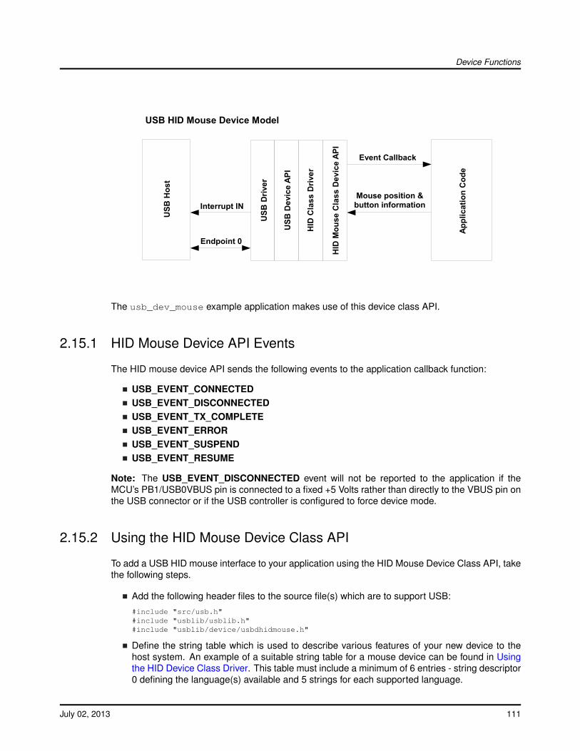
Device Functions
USB
Hos
t
USB
Driv
er
USB
Dev
ice
API
HID
Cla
ss D
river
Appl
icat
ion
Cod
e
Endpoint 0
Mouse position &button information
USB HID Mouse Device Model
Interrupt IN
HID
Mou
se C
lass
Dev
ice
API
Event Callback
The usb_dev_mouse example application makes use of this device class API.
2.15.1 HID Mouse Device API Events
The HID mouse device API sends the following events to the application callback function:
USB_EVENT_CONNECTEDUSB_EVENT_DISCONNECTEDUSB_EVENT_TX_COMPLETEUSB_EVENT_ERRORUSB_EVENT_SUSPENDUSB_EVENT_RESUME
Note: The USB_EVENT_DISCONNECTED event will not be reported to the application if theMCU’s PB1/USB0VBUS pin is connected to a fixed +5 Volts rather than directly to the VBUS pin onthe USB connector or if the USB controller is configured to force device mode.
2.15.2 Using the HID Mouse Device Class API
To add a USB HID mouse interface to your application using the HID Mouse Device Class API, takethe following steps.
Add the following header files to the source file(s) which are to support USB:#include "src/usb.h"#include "usblib/usblib.h"#include "usblib/device/usbdhidmouse.h"
Define the string table which is used to describe various features of your new device to thehost system. An example of a suitable string table for a mouse device can be found in Usingthe HID Device Class Driver. This table must include a minimum of 6 entries - string descriptor0 defining the language(s) available and 5 strings for each supported language.
July 02, 2013 111
Device Functions
Define a tUSBDHIDMouseDevice structure and initialize all fields as required for your applica-tion.const tUSBDHIDMouseDevice g_sMouseDevice ={
//// The Vendor ID you have been assigned by USB-IF.//USB_VID_YOUR_VENDOR_ID,
//// The product ID you have assigned for this device.//USB_PID_YOUR_PRODUCT_ID,
//// The power consumption of your device in milliamps.//POWER_CONSUMPTION_MA,
//// The value to be passed to the host in the USB configuration descriptor’s// bmAttributes field.//USB_CONF_ATTR_SELF_PWR,
//// A pointer to your mouse callback event handler.//YourMouseHandler,
//// A value that you want passed to the callback alongside every event.//(void *)&g_sYourInstanceData,
//// A pointer to your string table.//g_pStringDescriptors,
//// The number of entries in your string table. This must equal// (1 + (5 * (num languages))).//NUM_STRING_DESCRIPTORS
};
Add a mouse event handler function, YourMouseHandler in the previous exam-ple, to your application. A minimal implementation can ignore all events thoughUSB_EVENT_TX_COMPLETE can be used to ensure that mouse messages are not sentwhen a previous report is still in transit to the host. Attempts to send a new mouse re-port when the previous report has not yet been acknowledged will result in return codeMOUSE_ERR_TX_ERROR from USBDHIDMouseStateChange().From your main initialization function call the HID mouse device API initialization function toconfigure the USB controller and place the device on the bus.
pvDevice = USBDHIDMouseInit(0, &g_sMouseDevice);
Assuming pvDevice returned is not NULL, your mouse device is now ready to communicatewith a USB host.Once the host connects, your mouse event handler will be sent USB_EVENT_CONNECTEDafter which calls can be made to USBDHIDMouseStateChange()to inform the host of mouseposition and button state changes.
112 July 02, 2013
Device Functions
2.16 HID Mouse Device Class API Definitions
Data StructurestUSBDHIDMouseDevice
DefinesMOUSE_ERR_NOT_CONFIGUREDMOUSE_ERR_TX_ERRORMOUSE_REPORT_BUTTON_1MOUSE_REPORT_BUTTON_2MOUSE_REPORT_BUTTON_3MOUSE_SUCCESS
Functionsvoid ∗ USBDHIDMouseCompositeInit (uint32_t ui32Index, tUSBDHIDMouseDevice∗psMouseDevice, tCompositeEntry ∗psCompEntry)void ∗ USBDHIDMouseInit (uint32_t ui32Index, tUSBDHIDMouseDevice ∗psMouseDevice)void USBDHIDMousePowerStatusSet (void ∗pvMouseDevice, uint8_t ui8Power)bool USBDHIDMouseRemoteWakeupRequest (void ∗pvMouseDevice)void ∗ USBDHIDMouseSetCBData (void ∗pvMouseDevice, void ∗pvCBData)uint32_t USBDHIDMouseStateChange (void ∗pvMouseDevice, int8_t i8DeltaX, int8_ti8DeltaY, uint8_t ui8Buttons)void USBDHIDMouseTerm (void ∗pvMouseDevice)
2.16.1 Detailed Description
The macros and functions defined in this section can be found in header filedevice/usbdhidmouse.h.
2.16.2 Data Structure Documentation
2.16.2.1 tUSBDHIDMouseDevice
Definition:typedef struct{
const uint16_t ui16VID;const uint16_t ui16PID;const uint16_t ui16MaxPowermA;const uint8_t ui8PwrAttributes;tUSBCallbackconst pfnCallback;
July 02, 2013 113
Device Functions
void *pvCBData;const uint8_t *const *ppui8StringDescriptors;const uint32_t ui32NumStringDescriptors;tHIDMouseInstance sPrivateData;
}tUSBDHIDMouseDevice
Members:ui16VID The vendor ID that this device is to present in the device descriptor.ui16PID The product ID that this device is to present in the device descriptor.ui16MaxPowermA The maximum power consumption of the device, expressed in milliamps.ui8PwrAttributes Indicates whether the device is self- or bus-powered and whether or
not it supports remote wakeup. Valid values are USB_CONF_ATTR_SELF_PWR orUSB_CONF_ATTR_BUS_PWR, optionally ORed with USB_CONF_ATTR_RWAKE.
pfnCallback A pointer to the callback function which will be called to notify the application ofevents relating to the operation of the mouse.
pvCBData A client-supplied pointer which will be sent as the first parameter in all calls madeto the mouse callback, pfnCallback.
ppui8StringDescriptors A pointer to the string descriptor array for this device. This arraymust contain the following string descriptor pointers in this order. Language descriptor,Manufacturer name string (language 1), Product name string (language 1), Serial numberstring (language 1), HID Interface description string (language 1), Configuration descriptionstring (language 1).If supporting more than 1 language, the descriptor block (except for string descriptor 0)must be repeated for each language defined in the language descriptor.
ui32NumStringDescriptors The number of descriptors provided in the ppStringDescriptorsarray. This must be (1 + (5 * (num languages))).
sPrivateData The private instance data for this device. This memory must remain accessiblefor as long as the mouse device is in use and must not be modified by any code outsidethe HID mouse driver.
Description:This structure is used by the application to define operating parameters for the HID mousedevice.
2.16.3 Define Documentation
2.16.3.1 MOUSE_ERR_NOT_CONFIGURED
Definition:#define MOUSE_ERR_NOT_CONFIGURED
Description:USBDHIDMouseStateChange returns this value if it is called before the USB host has con-nected and configured the device. All mouse state information passed on the call will havebeen ignored.
114 July 02, 2013
Device Functions
2.16.3.2 MOUSE_ERR_TX_ERROR
Definition:#define MOUSE_ERR_TX_ERROR
Description:This return code from USBDHIDMouseStateChange indicates that an error was reported whileattempting to send a report to the host. A client should assume that the host has disconnectedif this return code is seen.
2.16.3.3 MOUSE_REPORT_BUTTON_1
Definition:#define MOUSE_REPORT_BUTTON_1
Description:Setting this bit in the ui8Buttons parameter to USBDHIDMouseStateChange indicates to theUSB host that button 1 on the mouse is pressed.
2.16.3.4 MOUSE_REPORT_BUTTON_2
Definition:#define MOUSE_REPORT_BUTTON_2
Description:Setting this bit in the ui8Buttons parameter to USBDHIDMouseStateChange indicates to theUSB host that button 2 on the mouse is pressed.
2.16.3.5 MOUSE_REPORT_BUTTON_3
Definition:#define MOUSE_REPORT_BUTTON_3
Description:Setting this bit in the ui8Buttons parameter to USBDHIDMouseStateChange indicates to theUSB host that button 3 on the mouse is pressed.
2.16.3.6 MOUSE_SUCCESS
Definition:#define MOUSE_SUCCESS
Description:This return code from USBDHIDMouseStateChange indicates success.
July 02, 2013 115
Device Functions
2.16.4 Function Documentation
2.16.4.1 USBDHIDMouseCompositeInit
Initializes HID mouse device operation for a given USB controller.
Prototype:void *USBDHIDMouseCompositeInit(uint32_t ui32Index,
tUSBDHIDMouseDevice *psMouseDevice,tCompositeEntry *psCompEntry)
Parameters:ui32Index is the index of the USB controller which is to be initialized for HID mouse device
operation.psMouseDevice points to a structure containing parameters customizing the operation of the
HID mouse device.psCompEntry is the composite device entry to initialize when creating a composite device.
Description:This call is very similar to USBDHIDMouseInit() except that it is used for initializing an instanceof the HID mouse device for use in a composite device. If this HID mouse is part of a compositedevice, then the psCompEntry should point to the composite device entry to initialize. This ispart of the array that is passed to the USBDCompositeInit() function.
Returns:Returns zero on failure or a non-zero instance value that should be used with the remainingUSB HID Mouse APIs.
2.16.4.2 USBDHIDMouseInit
Initializes HID mouse device operation for a given USB controller.
Prototype:void *USBDHIDMouseInit(uint32_t ui32Index,
tUSBDHIDMouseDevice *psMouseDevice)
Parameters:ui32Index is the index of the USB controller which is to be initialized for HID mouse device
operation.psMouseDevice points to a structure containing parameters customizing the operation of the
HID mouse device.
Description:An application wishing to offer a USB HID mouse interface to a USB host must call this functionto initialize the USB controller and attach the mouse device to the USB bus. This functionperforms all required USB initialization.
On successful completion, this function will return the psMouseDevice pointer passed to it.This must be passed on all future calls to the HID mouse device driver.
116 July 02, 2013

Device Functions
When a host connects and configures the device, the application callback will receiveUSB_EVENT_CONNECTED after which calls can be made to USBDHIDMouseStateChange()to report pointer movement and button presses to the host.
Note:The application must not make any calls to the lower level USB device interfaces if interactingwith USB via the USB HID mouse device API. Doing so will cause unpredictable (though almostcertainly unpleasant) behavior.
Returns:Returns NULL on failure or the psMouseDevice pointer on success.
2.16.4.3 USBDHIDMousePowerStatusSet
Reports the device power status (bus- or self-powered) to the USB library.
Prototype:voidUSBDHIDMousePowerStatusSet(void *pvMouseDevice,
uint8_t ui8Power)
Parameters:pvMouseDevice is the pointer to the mouse device instance structure.ui8Power indicates the current power status, either USB_STATUS_SELF_PWR or
USB_STATUS_BUS_PWR.
Description:Applications which support switching between bus- or self-powered operation should call thisfunction whenever the power source changes to indicate the current power status to the USBlibrary. This information is required by the USB library to allow correct responses to be providedwhen the host requests status from the device.
Returns:None.
2.16.4.4 USBDHIDMouseRemoteWakeupRequest
Requests a remote wake up to resume communication when in suspended state.
Prototype:boolUSBDHIDMouseRemoteWakeupRequest(void *pvMouseDevice)
Parameters:pvMouseDevice is the pointer to the mouse device instance structure.
Description:When the bus is suspended, an application which supports remote wake up (advertised to thehost via the configuration descriptor) may call this function to initiate remote wake up signalingto the host. If the remote wake up feature has not been disabled by the host, this will causethe bus to resume operation within 20mS. If the host has disabled remote wake up, false willbe returned to indicate that the wake up request was not successful.
July 02, 2013 117
Device Functions
Returns:Returns true if the remote wake up is not disabled and the signaling was started or false ifremote wake up is disabled or if signaling is currently ongoing following a previous call to thisfunction.
2.16.4.5 USBDHIDMouseSetCBData
Sets the client-specific pointer parameter for the mouse callback.
Prototype:void *USBDHIDMouseSetCBData(void *pvMouseDevice,
void *pvCBData)
Parameters:pvMouseDevice is the pointer to the mouse device instance structure.pvCBData is the pointer that client wishes to be provided on each event sent to the mouse
callback function.
Description:The client uses this function to change the callback pointer passed in the first parameter on allcallbacks to the pfnCallback function passed on USBDHIDMouseInit().
If a client wants to make runtime changes in the callback pointer, it must ensure that the pv-MouseDevice structure passed to USBDHIDMouseInit() resides in RAM. If this structure is inflash, callback data changes are not possible.
Returns:Returns the previous callback pointer that was set for this instance.
2.16.4.6 USBDHIDMouseStateChange
Reports a mouse state change, pointer movement or button press, to the USB host.
Prototype:uint32_tUSBDHIDMouseStateChange(void *pvMouseDevice,
int8_t i8DeltaX,int8_t i8DeltaY,uint8_t ui8Buttons)
Parameters:pvMouseDevice is the pointer to the mouse device instance structure.i8DeltaX is the relative horizontal pointer movement that the application wishes to report. Valid
values are in the range [-127, 127] with positive values indicating movement to the right.i8DeltaY is the relative vertical pointer movement that the application wishes to report. Valid
values are in the range [-127, 127] with positive values indicating downward movement.ui8Buttons is a bit mask indicating which (if any) of the three mouse buttons is
pressed. Valid values are logical OR combinations of MOUSE_REPORT_BUTTON_1,MOUSE_REPORT_BUTTON_2 and MOUSE_REPORT_BUTTON_3.
118 July 02, 2013
Device Functions
Description:This function is called to report changes in the mouse state to the USB host. These changescan be movement of the pointer, reported relative to its previous position, or changes in thestates of up to 3 buttons that the mouse may support. The return code indicates whether ornot the mouse report could be sent to the host. In cases where a previous report is still beingtransmitted, MOUSE_ERR_TX_ERROR will be returned and the state change will be ignored.
Returns:Returns MOUSE_SUCCESS on success, MOUSE_ERR_TX_ERROR if an error occurredwhile attempting to schedule transmission of the mouse report to the host (typically due to aprevious report which has not yet completed transmission or due to disconnection of the host)or MOUSE_ERR_NOT_CONFIGURED if called before a host has connected to and configuredthe device.
2.16.4.7 USBDHIDMouseTerm
Shuts down the HID mouse device.
Prototype:voidUSBDHIDMouseTerm(void *pvMouseDevice)
Parameters:pvMouseDevice is the pointer to the device instance structure.
Description:This function terminates HID mouse operation for the instance supplied and removes the devicefrom the USB bus. Following this call, the pvMouseDevice instance may not me used in anyother call to the HID mouse device other than USBDHIDMouseInit().
Returns:None.
2.17 HID Keyboard Device Class API
As with the HID Mouse Device Class API described above, the HID Keyboard Device Class APIprovides an easy-to-use high-level interface for applications wishing to appear to the USB host as aBIOS-compatible keyboard. The keyboard supports up to 6 simultaneously pressed, non-modifierkeys and up to 5 state indication LEDs.
Key press and release notifications along with the state of the modifier keys (Shift, Ctrl, Alt, etc.)are passed to the API in a single API call and a callback informs the application whenever the hostrequests that the LED states be changed.
Keys are identified to the API by means of USB HID key usage codes. A subset ofthese are defined in the header file usbhid.h and the full set can be found in the doc-ument "Universal Serial Bus (USB) HID Usage Tables" which can be downloaded fromhttp://www.usb.org/developers/devclass_docs/Hut1_12.pdf.
July 02, 2013 119
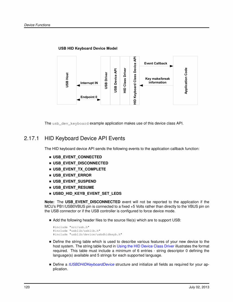
Device Functions
USB
Hos
t
USB
Driv
er
USB
Dev
ice
API
HID
Cla
ss D
river
Appl
icat
ion
Cod
e
Endpoint 0
Key make/breakinformation
USB HID Keyboard Device Model
Interrupt IN
HID
Key
boar
d C
lass
Dev
ice
API
Event Callback
The usb_dev_keyboard example application makes use of this device class API.
2.17.1 HID Keyboard Device API Events
The HID keyboard device API sends the following events to the application callback function:
USB_EVENT_CONNECTED
USB_EVENT_DISCONNECTED
USB_EVENT_TX_COMPLETE
USB_EVENT_ERROR
USB_EVENT_SUSPEND
USB_EVENT_RESUME
USBD_HID_KEYB_EVENT_SET_LEDS
Note: The USB_EVENT_DISCONNECTED event will not be reported to the application if theMCU’s PB1/USB0VBUS pin is connected to a fixed +5 Volts rather than directly to the VBUS pin onthe USB connector or if the USB controller is configured to force device mode.
Add the following header files to the source file(s) which are to support USB:
#include "src/usb.h"#include "usblib/usblib.h"#include "usblib/device/usbdhidkeyb.h"
Define the string table which is used to describe various features of your new device to thehost system. The string table found in Using the HID Device Class Driver illustrates the formatrequired. This table must include a minimum of 6 entries - string descriptor 0 defining thelanguage(s) available and 5 strings for each supported language.
Define a tUSBDHIDKeyboardDevice structure and initialize all fields as required for your ap-plication.
120 July 02, 2013
Device Functions
const tUSBDHIDKeyboardDevice g_sKeyboardDevice ={
//// The Vendor ID you have been assigned by USB-IF.//USB_VID_YOUR_VENDOR_ID,
//// The product ID you have assigned for this device.//USB_PID_YOUR_PRODUCT_ID,
//// The power consumption of your device in milliamps.//POWER_CONSUMPTION_MA,
//// The value to be passed to the host in the USB configuration descriptor’s// bmAttributes field.//USB_CONF_ATTR_SELF_PWR,
//// A pointer to your keyboard callback event handler.//YourKeyboardHandler,
//// A value that you want passed to the callback alongside every event.//(void *)&g_sYourInstanceData,
//// A pointer to your string table.//g_pStringDescriptors,
//// The number of entries in your string table. This must equal// (1 + (5 * (num languages))).//NUM_STRING_DESCRIPTORS
};
Add a keyboard event handler function, YourKeyboardHandler in the previous example, to yourapplication. A minimal implementation can ignore all events since key information is bufferedin the API and sent later if USBDHIDKeyboardKeyStateChange() is called while a previousreport transmission remains unacknowledged.
From your main initialization function call the HID keyboard device API initialization function toconfigure the USB controller and place the device on the bus.
pvDevice = USBDHIDKeyboardInit(0, &g_sKeyboardDevice);
Assuming pvDevice returned is not NULL, your keyboard device is now ready to communicatewith a USB host.
Once the host connects, your keyboard event handler will be sentUSB_EVENT_CONNECTED after which calls can be made to USBDHIDKeyboardKeyState-Change()to inform the host of key press and release events.
July 02, 2013 121
Device Functions
2.18 HID Keyboard Device Class API Definitions
Data StructurestUSBDHIDKeyboardDevice
DefinesKEYB_ERR_NOT_CONFIGUREDKEYB_ERR_NOT_FOUNDKEYB_ERR_TOO_MANY_KEYSKEYB_ERR_TX_ERRORKEYB_MAX_CHARS_PER_REPORTKEYB_SUCCESSUSBD_HID_KEYB_EVENT_SET_LEDS
Functionsvoid ∗ USBDHIDKeyboardCompositeInit (uint32_t ui32Index, tUSBDHIDKeyboardDevice∗psHIDKbDevice, tCompositeEntry ∗psCompEntry)void ∗ USBDHIDKeyboardInit (uint32_t ui32Index, tUSBDHIDKeyboardDevice∗psHIDKbDevice)uint32_t USBDHIDKeyboardKeyStateChange (void ∗pvKeyboardDevice, uint8_t ui8Modifiers,uint8_t ui8UsageCode, bool bPress)void USBDHIDKeyboardPowerStatusSet (void ∗pvKeyboardDevice, uint8_t ui8Power)bool USBDHIDKeyboardRemoteWakeupRequest (void ∗pvKeyboardDevice)void ∗ USBDHIDKeyboardSetCBData (void ∗pvKeyboardDevice, void ∗pvCBData)void USBDHIDKeyboardTerm (void ∗pvKeyboardDevice)
2.18.1 Detailed Description
The macros and functions defined in this section can be found in header filedevice/usbdhidkeyb.h.
2.18.2 Data Structure Documentation
2.18.2.1 tUSBDHIDKeyboardDevice
Definition:typedef struct{
const uint16_t ui16VID;const uint16_t ui16PID;const uint16_t ui16MaxPowermA;
122 July 02, 2013
Device Functions
const uint8_t ui8PwrAttributes;tUSBCallbackconst pfnCallback;void *pvCBData;const uint8_t *const *ppui8StringDescriptors;const uint32_t ui32NumStringDescriptors;tHIDKeyboardInstance sPrivateData;
}tUSBDHIDKeyboardDevice
Members:ui16VID The vendor ID that this device is to present in the device descriptor.ui16PID The product ID that this device is to present in the device descriptor.ui16MaxPowermA The maximum power consumption of the device, expressed in milliamps.ui8PwrAttributes Indicates whether the device is self- or bus-powered and whether or
not it supports remote wakeup. Valid values are USB_CONF_ATTR_SELF_PWR orUSB_CONF_ATTR_BUS_PWR, optionally ORed with USB_CONF_ATTR_RWAKE.
pfnCallback A pointer to the callback function which will be called to notify the applicationof general events and those related to reception of Output and Feature reports via the(optional) interrupt OUT endpoint.
pvCBData A client-supplied pointer which will be sent as the first parameter in all calls madeto the keyboard callback, pfnCallback.
ppui8StringDescriptors A pointer to the string descriptor array for this device. This arraymust contain the following string descriptor pointers in this order. Language descriptor,Manufacturer name string (language 1), Product name string (language 1), Serial numberstring (language 1), HID Interface description string (language 1), Configuration descriptionstring (language 1).If supporting more than 1 language, the descriptor block (except for string descriptor 0)must be repeated for each language defined in the language descriptor.
ui32NumStringDescriptors The number of descriptors provided in the ppStringDescriptorsarray. This must be (1 + (5 * (num languages))).
sPrivateData The private instance data for this device. This memory must remain accessiblefor as long as the keyboard device is in use and must not be modified by any code outsidethe HID keyboard driver.
Description:This structure is used by the application to define operating parameters for the HID keyboarddevice.
2.18.3 Define Documentation
2.18.3.1 KEYB_ERR_NOT_CONFIGURED
Definition:#define KEYB_ERR_NOT_CONFIGURED
Description:USBDHIDKeyboardKeyStateChange returns this value if it is called before the USB host hasconnected and configured the device. Any key usage code passed will be stored and passedto the host once configuration completes.
July 02, 2013 123

Device Functions
2.18.3.2 KEYB_ERR_NOT_FOUND
Definition:#define KEYB_ERR_NOT_FOUND
Description:USBDHIDKeyboardKeyStateChange returns this value if it is called with the bPress parameterset to false but with a ui8UsageCode parameter which does does not indicate a key that iscurrently recorded as being pressed. This may occur if an attempt was previously made toreport more than 6 pressed keys and the earlier pressed keys are released before the laterones. This condition is benign and should not be used to indicate a host disconnection orserious error.
2.18.3.3 KEYB_ERR_TOO_MANY_KEYS
Definition:#define KEYB_ERR_TOO_MANY_KEYS
Description:This return code from USBDHIDKeyboardKeyStateChange indicates that an attempt has beenmade to record more than 6 simultaneously pressed, non-modifier keys. The USB HID BIOSkeyboard protocol allows no more than 6 pressed keys to be reported at one time. Until at leastone key is released, the device will report a roll over error to the host each time it is asked forthe keyboard input report.
2.18.3.4 KEYB_ERR_TX_ERROR
Definition:#define KEYB_ERR_TX_ERROR
Description:This return code from USBDHIDKeyboardKeyStateChange indicates that an error was reportedwhile attempting to send a report to the host. A client should assume that the host has discon-nected if this return code is seen.
2.18.3.5 KEYB_MAX_CHARS_PER_REPORT
Definition:#define KEYB_MAX_CHARS_PER_REPORT
Description:The maximum number of simultaneously-pressed, non-modifier keys that the HID BIOS key-board protocol can send at once. Attempts to send more pressed keys than this will result in arollover error being reported to the host and KEYB_ERR_TOO_MANY_KEYS being returnedfrom USBDHIDKeyboardKeyStateChange.
124 July 02, 2013

Device Functions
2.18.3.6 KEYB_SUCCESS
Definition:#define KEYB_SUCCESS
Description:This return code from USBDHIDKeyboardKeyStateChange indicates success.
2.18.3.7 USBD_HID_KEYB_EVENT_SET_LEDS
Definition:#define USBD_HID_KEYB_EVENT_SET_LEDS
Description:This event indicates that the keyboard LED states are to be set. The ui32MsgValue parametercontains the requested state for each of the LEDs defined as a collection of ORed bits where a 1indicates that the LED is to be turned on and a 0 indicates that it should be turned off. The indi-vidual LED bits are defined using labels HID_KEYB_NUM_LOCK, HID_KEYB_CAPS_LOCK,HID_KEYB_SCROLL_LOCK, HID_KEYB_COMPOSE and HID_KEYB_KANA.
2.18.4 Function Documentation
2.18.4.1 USBDHIDKeyboardCompositeInit
Initializes HID keyboard device operation for a given USB controller.
Prototype:void *USBDHIDKeyboardCompositeInit(uint32_t ui32Index,
tUSBDHIDKeyboardDevice *psHIDKbDevice,tCompositeEntry *psCompEntry)
Parameters:ui32Index is the index of the USB controller which is to be initialized for HID keyboard device
operation.psHIDKbDevice points to a structure containing parameters customizing the operation of the
HID keyboard device.psCompEntry is the composite device entry to initialize when creating a composite device.
Description:This call is very similar to USBDKeyboardInit() except that it is used for initializing an instanceof the HID keyboard device for use in a composite device. If this HID keyboard is part ofa composite device, then the psCompEntry should point to the composite device entry toinitialize. This is part of the array that is passed to the USBDCompositeInit() function.
Returns:Returns zero on failure or a non-zero instance value that should be used with the remainingUSB HID Keyboard APIs.
July 02, 2013 125
Device Functions
2.18.4.2 USBDHIDKeyboardInit
Initializes HID keyboard device operation for a given USB controller.
Prototype:void *USBDHIDKeyboardInit(uint32_t ui32Index,
tUSBDHIDKeyboardDevice *psHIDKbDevice)
Parameters:ui32Index is the index of the USB controller which is to be initialized for HID keyboard device
operation.psHIDKbDevice points to a structure containing parameters customizing the operation of the
HID keyboard device.
Description:An application wishing to offer a USB HID keyboard interface to a USB host must call thisfunction to initialize the USB controller and attach the keyboard device to the USB bus. Thisfunction performs all required USB initialization.
On successful completion, this function will return the psHIDKbDevice pointer passed to it.This must be passed on all future calls to the HID keyboard device driver.
When a host connects and configures the device, the application callback will receiveUSB_EVENT_CONNECTED after which calls can be made to USBDHIDKeyboardKeyStat-eChange() to report key presses and releases to the USB host.
Note:The application must not make any calls to the lower level USB device interfaces if interact-ing with USB via the USB HID keyboard device class API. Doing so will cause unpredictable(though almost certainly unpleasant) behavior.
Returns:Returns NULL on failure or the psHIDKbDevice pointer on success.
2.18.4.3 USBDHIDKeyboardKeyStateChange
Reports a key state change to the USB host.
Prototype:uint32_tUSBDHIDKeyboardKeyStateChange(void *pvKeyboardDevice,
uint8_t ui8Modifiers,uint8_t ui8UsageCode,bool bPress)
Parameters:pvKeyboardDevice is the pointer to the device instance structure as returned by USBDHID-
KeyboardInit().ui8Modifiers contains the states of each of the keyboard modifiers (left/right shift,
ctrl, alt or GUI keys). Valid values are logical OR combinations of the la-bels HID_KEYB_LEFT_CTRL, HID_KEYB_LEFT_SHIFT, HID_KEYB_LEFT_ALT,HID_KEYB_LEFT_GUI, HID_KEYB_RIGHT_CTRL, HID_KEYB_RIGHT_SHIFT,
126 July 02, 2013
Device Functions
HID_KEYB_RIGHT_ALT and HID_KEYB_RIGHT_GUI. Presence of one of thesebit flags indicates that the relevant modifier key is pressed and absence indicates that it isreleased.
ui8UsageCode is the usage code of the key whose state has changed. If only modifier keyshave changed, HID_KEYB_USAGE_RESERVED should be passed in this parameter.
bPress is true if the key has been pressed or false if it has been released. If only modifierkeys have changed state, this parameter is ignored.
Description:This function adds or removes a key usage code from the list of keys currently pressed andschedules a report transmission to the host to inform it of the new keyboard state. If themaximum number of simultaneous key presses are already recorded, the report to the host willcontain the rollover error code, HID_KEYB_USAGE_ROLLOVER instead of key usage codesand the caller will receive return code KEYB_ERR_TOO_MANY_KEYS.
Returns:Returns KEYB_SUCCESS if the key usage code was added to or removed from thecurrent list successfully. KEYB_ERR_TOO_MANY_KEYS is returned if an attempt ismade to press a 7th key (the BIOS keyboard protocol can report no more than 6 si-multaneously pressed keys). If called before the USB host has configured the device,KEYB_ERR_NOT_CONFIGURED is returned and, if an error is reported while attempting totransmit the report, KEYB_ERR_TX_ERROR is returned. If an attempt is made to remove akey from the pressed list (by setting parameter bPressed to false) but the key usage code isnot found, KEYB_ERR_NOT_FOUND is returned.
2.18.4.4 USBDHIDKeyboardPowerStatusSet
Reports the device power status (bus or self powered) to the USB library.
Prototype:voidUSBDHIDKeyboardPowerStatusSet(void *pvKeyboardDevice,
uint8_t ui8Power)
Parameters:pvKeyboardDevice is the pointer to the keyboard device instance structure.ui8Power indicates the current power status, either USB_STATUS_SELF_PWR or
USB_STATUS_BUS_PWR.
Description:Applications which support switching between bus or self powered operation should call thisfunction whenever the power source changes to indicate the current power status to the USBlibrary. This information is required by the USB library to allow correct responses to be providedwhen the host requests status from the device.
Returns:None.
2.18.4.5 USBDHIDKeyboardRemoteWakeupRequest
Requests a remote wake up to resume communication when in suspended state.
July 02, 2013 127

Device Functions
Prototype:boolUSBDHIDKeyboardRemoteWakeupRequest(void *pvKeyboardDevice)
Parameters:pvKeyboardDevice is the pointer to the keyboard device instance structure.
Description:When the bus is suspended, an application which supports remote wake up (advertised to thehost via the configuration descriptor) may call this function to initiate remote wake up signalingto the host. If the remote wake up feature has not been disabled by the host, this will causethe bus to resume operation within 20mS. If the host has disabled remote wake up, false willbe returned to indicate that the wake up request was not successful.
Returns:Returns true if the remote wake up is not disabled and the signaling was started or false ifremote wake up is disabled or if signaling is currently ongoing following a previous call to thisfunction.
2.18.4.6 USBDHIDKeyboardSetCBData
Sets the client-specific pointer parameter for the keyboard callback.
Prototype:void *USBDHIDKeyboardSetCBData(void *pvKeyboardDevice,
void *pvCBData)
Parameters:pvKeyboardDevice is the pointer to the device instance structure as returned by USBDHID-
KeyboardInit().pvCBData is the pointer that client wishes to be provided on each event sent to the keyboard
callback function.
Description:The client uses this function to change the callback pointer passed in the first parameter on allcallbacks to the pfnCallback function passed on USBDHIDKeyboardInit().
If a client wants to make runtime changes in the callback pointer, it must ensure that the pvKey-boardDevice structure passed to USBDHIDKeyboardInit() resides in RAM. If this structure is inflash, callback data changes will not be possible.
Returns:Returns the previous callback pointer that was set for this instance.
2.18.4.7 USBDHIDKeyboardTerm
Shuts down the HID keyboard device.
Prototype:voidUSBDHIDKeyboardTerm(void *pvKeyboardDevice)
128 July 02, 2013
Device Functions
Parameters:pvKeyboardDevice is the pointer to the device instance structure as returned by USBDHID-
KeyboardInit().
Description:This function terminates HID keyboard operation for the instance supplied and removes thedevice from the USB bus. Following this call, the pvKeyboardDevice instance may not meused in any other call to the HID keyboard device other than USBDHIDKeyboardInit().
Returns:None.
2.19 Mass Storage Device Class API
The USB mass storage device class allows an application to act as a physical storage device foruse by another USB application or for a host operating system. Because the type of storage canvary per application, the mass storage class abstracts the storage with a set of block based APIsthat are provided by the application to the USB library. These APIs allow the USB mass storageclass to call an external set of functions that actually perform the operations on the physical storagemedia. The storage APIs are given to the USB library’s mass storage device class initializationfunction and are called by the USB library whenever it needs to access the physical media. Themass storage class implementation does not require any run time calls once it is initialized. Thisis because all interaction with the mass storage class occur through the callback function that isprovided to the USB library’s mass storage class interface. The callback function is used to notifythe application when the device is being read, written or has gone idle. Depending on the operatingsystem and how it accesses the mass storage device, these callbacks may occur at a very rapidrate (once per block) or slower (once per file). The USB library’s mass storage class also providesan interface to inform the USB library when the media status has changed in case the physicalmedia can be ejected. This is important for devices like SD cards that can be removed before thedevice is connected or even while the device is running.
Note:Some care must be taken by the application if it wishes to share the media with the massstorage class. Proper access protection must be in place as the mass storage class may beusing the media access functions during the USB interrupt.
2.19.1 Initialization
The USB library’s mass storage class provides a simple interface to initialize the mass storage classand pass it the needed functions to access a device without having any knowledge of the physicalmedia. The USBDMSCInit() function is the only initialization required by the mass storage classand it uses the structure tUSBDMSCDevice to hold all customizable values for the mass storageclass.
2.19.2 Customization
The USB library’s mass storage class provides the ability to customize how the device is reported tothe USB host controller in the tUSBDMSCDevice structure. The members of this structure contain
July 02, 2013 129
Device Functions
all of the customizable parameters.
2.19.2.1 VID and PID
The VID and PID values reported to the host controller are provided in the usVID and usPID mem-bers of the tUSBDMSCDevice structure and should be valid for the application and unique for allvendors and devices. The mass storage device class also reports some class specific strings to theoperating system which can be customized in the pucVendor, pucProduct, and pucVersion structuremembers. These strings may or may not be requested by the USB host controller, however theyare required. The pucVendor member is an 8 byte character string for the Vendor, and should beexactly 8 bytes padded with spaces(for example: "TI "). The pucProduct member is a 16 characterstring that indicates the product type and it too should be padded out with spaces to 16 bytes(forexample: "Mass Storage "). The last customizable mass storage string is contained in pucVer-sion member and is a character based version which should be a 4 bytes padded with spaces (forexample: "1.00").
2.19.2.2 Power Configuration
The power configuration for the mass storage class device is held in two of the tUSBDMSCDevicemembers variables, usMaxPowermA and ucPwrAttributes. The usMaxPowermA variable holds themaximum power consumption for the device and is expressed in milliamps. The power configurationis held in the ucPwrAttributes member variable and indicates whether the device is self or buspowered. Valid values are USB_CONF_ATTR_SELF_PWR or USB_CONF_ATTR_BUS_PWR.
2.19.2.3 Device Strings
The remaining USB strings are contained in the ppui8StringDescriptors and are just like the stringsthat are used in every other device class in the USB library. The ppui8StringDescriptors is a pointerto the string descriptor array for this device. This array must contain the following string descriptorpointers in this order. Language descriptor, Manufacturer name string (language 1), Product namestring (language 1), Serial number string (language 1), MSC Interface description string (language1), Configuration description string (language 1). If the device is supporting more than 1 language,the descriptor block (except for string descriptor 0) must be repeated for each language defined inthe language descriptor. The number of descriptors provided in the ppui8StringDescriptors arraymust be ((5 + (num MSC strings)) ∗ (num languages)) + 1.
2.19.2.4 Media Access Functions
The media access functions are passed in to the USB mass storage device class in the sMedia-Functions member variable. This structure holds the access functions for the media used by thisinstance of the mass storage class device. All of the functions in this structure are required to befilled out with valid functions. These function will be called by the USB mass storage device classwhenever it needs to read or write the physical media and will assume fixed block sizes of 512 bytesfor the media.
130 July 02, 2013

Device Functions
2.19.2.5 Event Callbacks
In some cases the application may need to be informed when the state of the mass stor-age device has changed. The pfnEventCallback member of the tUSBDMSCDevice structureprovides event notification to applications for the following events: USBD_MSC_EVENT_IDLE,USBD_MSC_EVENT_READING, and USBD_MSC_WRITING. When the function of type tUSB-Callback is called, only the first two parameters pvCBData and ui32Event parameters are valid.The pvCBData is the value that was returned when the application called USBDMSCInit() and canbe used with other APIs. The ui32Event parameter is one of the USBD_MSC_EVENT_∗ values.
2.19.2.6 Misc Features
The mass storage class can be configured to use the uDMA or can function without DMA if theapplication does not require DMA. To enable the use of DMA the ulFlags value should have theUSBD_FLAG_USE_DMA bit set.
2.19.3 the Mass Storage Device Class:
The following sections has some coding examples for the initialization of the mass storage classstructures as well as how to call the initialization function itself.
Example: Device Structure
const tUSBDMSCDevice g_sMSCDevice ={
//// Vendor ID.//USB_VID_TI_1CBE,
//// Product ID.//USB_PID_MSC,
//// Vendor Information.//"TI ",
//// Product Identification.//"Mass Storage ",
//// Revision.//"1.00",
//// 500mA.500,
//// Bus Powered.//
July 02, 2013 131

Device Functions
USB_CONF_ATTR_BUS_PWR,
//// A list of string descriptors and the number of descriptors.//g_pStringDescriptors,NUM_STRING_DESCRIPTORS,
//// The media access functions.//{
USBDMSCStorageOpen,USBDMSCStorageClose,USBDMSCStorageRead,USBDMSCStorageWrite,USBDMSCStorageNumBlocks
},
//// The event notification call back function.//USBMSCDEventCallback,
//// No DMA in use by this application.//0
};
The initialization and configuration calls for the USB library’s mass storage device class are handledby a single call that passes in the tUSBDMSCDevice structure.
Example: Initialization code
//// Pass our device information to the USB library and place the device// on the bus.//USBDMSCInit(0, (tUSBDMSCDevice *)&g_sMSCDevice);
//// Drop into the main loop.//while(1){}
The application’s event call back function provides the application with notifications of changes inthe USB mass storage class. The application can use this information to update it’s own state. Theevents may occur in rapid succession and the application must be careful not to spend much timein this function as it is called from a interrupt handler. The application should expect many calls tothis function during USB transfers.
Example: Callback handler.
uint32_tUSBDMSCEventCallback(void *pvCBData, uint32_t ui32Event,
uint32_t ui32MsgParam, void *pvMsgData){
switch(ui32Event){
132 July 02, 2013
Device Functions
//// Writing to the device.//case USBD_MSC_EVENT_WRITING:{
//// Handle write case.//
...
break;}
//// Reading from the device.//case USBD_MSC_EVENT_READING:{
//// Handle read case.//
...
break;}case USBD_MSC_EVENT_IDLE:{
//// Handle idle case.//
...
}default:{
break;}
}return(0);
}
2.19.4 Using the Composite Mass Storage Device Class
When using the mass storage device class in a composite device, the configuration of the deviceis very similar to how it is configured as a non-composite device. Follow all of the configurationsteps in the previous section with the exception of calling USBDMSCCompositeInit() instead ofUSBDMSCInit(). This will prepare an instance of the mass storage device class to be enumeratedas part of a composite device. The return value from the USBDMSCCompositeInit() function shouldbe placed in the pvInstance member of the tCompositeEntry structure for the mass storage device.The code example below provides an example of how to initialize some of the structures necessaryto use the USB mass storage device class in a composite device.
//// These should be initialized with valid values for each class.//extern tUSBDMSCDevice g_sMSCDevice;
//
July 02, 2013 133
Device Functions
// The array of composite device entries.//tCompositeEntry psCompEntries[2];
//// Allocate the device data for the top level composite device class.//tUSBDCompositeDevice g_sCompDevice ={
//// Texas Intruments C-Series VID.//USB_VID_TI_1CBE,
//// Texas Intruments C-Series PID for composite serial device.//USB_PID_YOUR_COMPOSITE_PID,
//// This is in 2mA increments so 500mA.//250,
//// Bus powered device.//USB_CONF_ATTR_BUS_PWR,
//// Composite event handler.//EventHandler,
//// The string table.//g_pui8StringDescriptors,NUM_STRING_DESCRIPTORS,
//// The Composite device array.//2,g_psCompEntries
};
//// The OTHER_SIZES here are the sizes of the descriptor data for other classes// that are part of the composite device.//#define DESCRIPTOR_DATA_SIZE (COMPOSITE_DMSC_SIZE + OTHER_SIZES)uint8_t g_pui8DescriptorData[DESCRIPTOR_DATA_SIZE];
//// Save the instance data for this mass storage device.//pvAudioDevice = USBDMSCCompositeInit(0, &g_sMSCDevice, &psCompEntries[0]);
...
//// Initialize the USB controller as a composite device.//USBDCompositeInit(0, &g_sCompDevice, DESCRIPTOR_DATA_SIZE,
g_pui8DescriptorData);
134 July 02, 2013
Device Functions
All other API calls to the USB mass storage device class should use the value returned by US-BDAudioCompositeInit() when the API calls for a pvInstance pointer. Also when using the audiodevice in a composite device the COMPOSITE_DMSC_SIZE value should be added to the size ofthe g_pui8DescriptorData array as shown in the example above.
2.20 Mass Storage Device Class API Definitions
Data StructurestMSCDMediatUSBDMSCDevice
DefinesCOMPOSITE_DMSC_SIZEUSBD_MSC_EVENT_IDLEUSBD_MSC_EVENT_READINGUSBD_MSC_EVENT_WRITING
Functionsvoid ∗ USBDMSCCompositeInit (uint32_t ui32Index, tUSBDMSCDevice ∗psMSCDevice,tCompositeEntry ∗psCompEntry)void ∗ USBDMSCInit (uint32_t ui32Index, tUSBDMSCDevice ∗psMSCDevice)void USBDMSCMediaChange (void ∗pvMSCDevice, tUSBDMSCMediaStatus iMediaStatus)void USBDMSCTerm (void ∗pvMSCDevice)
2.20.1 Detailed Description
The macros and functions defined in this section can be found in header file device/usbdmsc.h.
2.20.2 Data Structure Documentation
2.20.2.1 tMSCDMedia
Definition:typedef struct{
void * (*pfnOpen)(uint32_t ui32Drive);void (*pfnClose)(void *pvDrive);uint32_t (*pfnBlockRead)(void *pvDrive,
uint8_t *pui8Data,uint32_t ui32Sector,
July 02, 2013 135
Device Functions
uint32_t ui32NumBlocks);uint32_t (*pfnBlockWrite)(void *pvDrive,
uint8_t *pui8Data,uint32_t ui32Sector,uint32_t ui32NumBlocks);
uint32_t (*pfnNumBlocks)(void *pvDrive);}tMSCDMedia
Members:pfnOpen This function is used to initialize and open the physical drive number associated with
the parameter ui32Drive. The function will return zero if the drive could not be opened forsome reason. In the case of removable device like an SD card this function should returnzero if the SD card is not present. The function returns a pointer to data that should bepassed to other APIs or it will return 0 if no drive was found.
pfnClosepfnBlockReadpfnBlockWritepfnNumBlocks
Description:Media Access functions.
2.20.2.2 tUSBDMSCDevice
Definition:typedef struct{
const uint16_t ui16VID;const uint16_t ui16PID;const uint8_t pui8Vendor[8];const uint8_t pui8Product[16];const uint8_t pui8Version[4];const uint16_t ui16MaxPowermA;const uint8_t ui8PwrAttributes;const uint8_t *const *ppui8StringDescriptors;const uint32_t ui32NumStringDescriptors;tMSCDMediaconst sMediaFunctions;tUSBCallbackconst pfnEventCallback;tMSCInstance sPrivateData;
}tUSBDMSCDevice
Members:ui16VID The vendor ID that this device is to present in the device descriptor.ui16PID The product ID that this device is to present in the device descriptor.pui8Vendor 8 byte vendor string.pui8Product 16 byte vendor string.pui8Version 4 byte vendor string.ui16MaxPowermA The maximum power consumption of the device, expressed in milliamps.
136 July 02, 2013
Device Functions
ui8PwrAttributes Indicates whether the device is self or bus-powered and whether ornot it supports remote wakeup. Valid values are USB_CONF_ATTR_SELF_PWR orUSB_CONF_ATTR_BUS_PWR, optionally ORed with USB_CONF_ATTR_RWAKE.
ppui8StringDescriptors A pointer to the string descriptor array for this device. This arraymust contain the following string descriptor pointers in this order. Language descriptor,Manufacturer name string (language 1), Product name string (language 1), Serial numberstring (language 1), MSC Interface description string (language 1), Configuration descrip-tion string (language 1).If supporting more than 1 language, the descriptor block (except for string descriptor 0)must be repeated for each language defined in the language descriptor.
ui32NumStringDescriptors The number of descriptors provided in the ppStringDescriptorsarray. This must be 1 + ((5 + (num HID strings)) * (num languages)).
sMediaFunctions This structure holds the access functions for the media used by this in-stance of the mass storage class device. All of the functions in this structure are requiredto be filled out with valid functions.
pfnEventCallback This is the callback function for various events that occur during mass stor-age class operation.
sPrivateData The private instance data for this device. This memory must remain accessiblefor as long as the MSC device is in use and must not be modified by any code outside theMSC class driver.
Description:The structure used by the application to define operating parameters for the mass storagedevice.
2.20.3 Define Documentation
2.20.3.1 COMPOSITE_DMSC_SIZE
Definition:#define COMPOSITE_DMSC_SIZE
Description:The size of the memory that should be allocated to create a configuration descriptor for a singleinstance of the USB Audio Device. This does not include the configuration descriptor which isautomatically ignored by the composite device class.
2.20.3.2 USBD_MSC_EVENT_IDLE
Definition:#define USBD_MSC_EVENT_IDLE
Description:This event indicates that the host has completed other operations and is no longer accessingthe device.
July 02, 2013 137
Device Functions
2.20.3.3 USBD_MSC_EVENT_READING
Definition:#define USBD_MSC_EVENT_READING
Description:This event indicates that the host is reading the storage media.
2.20.3.4 USBD_MSC_EVENT_WRITING
Definition:#define USBD_MSC_EVENT_WRITING
Description:This event indicates that the host is writing to the storage media.
2.20.4 Function Documentation
2.20.4.1 USBDMSCCompositeInit
This function should be called once for the mass storage class device to initialized basic operationand prepare for enumeration.
Prototype:void *USBDMSCCompositeInit(uint32_t ui32Index,
tUSBDMSCDevice *psMSCDevice,tCompositeEntry *psCompEntry)
Parameters:ui32Index is the index of the USB controller to initialize for mass storage class device opera-
tion.psMSCDevice points to a structure containing parameters customizing the operation of the
mass storage device.psCompEntry is the composite device entry to initialize when creating a composite device.
Description:In order for an application to initialize the USB device mass storage class, it must first call thisfunction with the a valid mass storage device class structure in the psMSCDevice parameter.This allows this function to initialize the USB controller and device code to be prepared toenumerate and function as a USB mass storage device. If this mass storage device is partof a composite device, then the psCompEntry should point to the composite device entry toinitialize. This is part of the array that is passed to the USBDCompositeInit() function.
This function returns a void pointer that must be passed in to all other APIs used by the massstorage class.
See the documentation on the tUSBDMSCDevice structure for more information on how toproperly fill the structure members.
138 July 02, 2013

Device Functions
Returns:Returns zero on failure or a non-zero instance value that should be used with the remainingUSB mass storage APIs.
2.20.4.2 USBDMSCInit
This function should be called once for the mass storage class device to initialized basic operationand prepare for enumeration.
Prototype:void *USBDMSCInit(uint32_t ui32Index,
tUSBDMSCDevice *psMSCDevice)
Parameters:ui32Index is the index of the USB controller to initialize for mass storage class device opera-
tion.psMSCDevice points to a structure containing parameters customizing the operation of the
mass storage device.
Description:In order for an application to initialize the USB device mass storage class, it must first call thisfunction with the a valid mass storage device class structure in the psMSCDevice parameter.This allows this function to initialize the USB controller and device code to be prepared toenumerate and function as a USB mass storage device.
This function returns a void pointer that must be passed in to all other APIs used by the massstorage class.
See the documentation on the tUSBDMSCDevice structure for more information on how toproperly fill the structure members.
Returns:Returns 0 on failure or a non-zero void pointer on success.
2.20.4.3 USBDMSCMediaChange
This function is used by an application if it can detect insertion or removal of the media.
Prototype:voidUSBDMSCMediaChange(void *pvMSCDevice,
tUSBDMSCMediaStatus iMediaStatus)
Parameters:pvMSCDevice is the mass storage device instance that had a media change.iMediaStatus is the updated status for the media.
Description:This function should be called by an application when it detects a change in the status of themedia in use by the USB mass storage class. The iMediaStatus parameter will indicate the
July 02, 2013 139

Device Functions
new status of the media and can also indicate that the application has no knowledge of themedia state.
There are currently the three following values for the iMediaStatus parameter:
eUSBDMSCMediaPresent indicates that the media is present or has been added.eUSBDMSCMediaNotPresent indicates that the media is not present or was removed.eUSBDMSCMediaUnknown indicates that the application has no knowledge of the mediastate and the USB mass storage class.
It will be left up to the application to call this function whenever it detects a change or simplycall it once with eUSBDMSCMediaUnknown and allow the mass storage class to infer the statefrom the remaining device APIs.
Note:It is recommended that the application use this function to inform the mass storage class ofmedia state changes as it will lead to a more responsive system.
Returns:None.
2.20.4.4 USBDMSCTerm
Shuts down the mass storage device.
Prototype:voidUSBDMSCTerm(void *pvMSCDevice)
Parameters:pvMSCDevice is the pointer to the device instance structure as returned by USBDMSCInit()
or USBDMSCInitComposite().
Description:This function terminates mass storage operation for the instance supplied and removes the de-vice from the USB bus. Following this call, the pvMSCDevice instance may not me used in anyother call to the mass storage device other than USBDMSCInit() or USBDMSCInitComposite().
Returns:None.
2.21 Using the USB Device API
If an existing USB Device Class Driver is not suitable for your application, you may choose todevelop your device using the lower-level USB Device API instead. This offers greater flexibility butinvolves somewhat more work. Creating a device application using the USB Device API involvesseveral steps:
Build device, configuration, interface and endpoint descriptor structures to describe your de-vice.
140 July 02, 2013
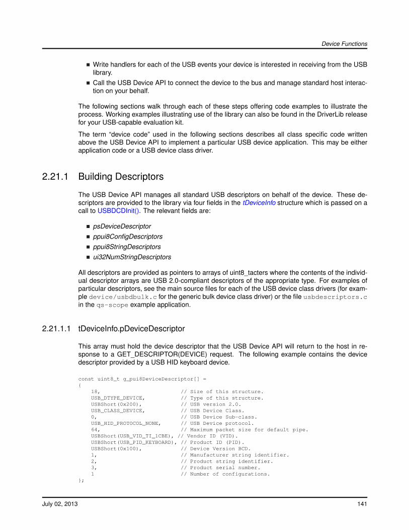
Device Functions
Write handlers for each of the USB events your device is interested in receiving from the USBlibrary.Call the USB Device API to connect the device to the bus and manage standard host interac-tion on your behalf.
The following sections walk through each of these steps offering code examples to illustrate theprocess. Working examples illustrating use of the library can also be found in the DriverLib releasefor your USB-capable evaluation kit.
The term “device code” used in the following sections describes all class specific code writtenabove the USB Device API to implement a particular USB device application. This may be eitherapplication code or a USB device class driver.
2.21.1 Building Descriptors
The USB Device API manages all standard USB descriptors on behalf of the device. These de-scriptors are provided to the library via four fields in the tDeviceInfo structure which is passed on acall to USBDCDInit(). The relevant fields are:
psDeviceDescriptorppui8ConfigDescriptorsppui8StringDescriptorsui32NumStringDescriptors
All descriptors are provided as pointers to arrays of uint8_tacters where the contents of the individ-ual descriptor arrays are USB 2.0-compliant descriptors of the appropriate type. For examples ofparticular descriptors, see the main source files for each of the USB device class drivers (for exam-ple device/usbdbulk.c for the generic bulk device class driver) or the file usbdescriptors.cin the qs-scope example application.
2.21.1.1 tDeviceInfo.pDeviceDescriptor
This array must hold the device descriptor that the USB Device API will return to the host in re-sponse to a GET_DESCRIPTOR(DEVICE) request. The following example contains the devicedescriptor provided by a USB HID keyboard device.
const uint8_t g_pui8DeviceDescriptor[] ={
18, // Size of this structure.USB_DTYPE_DEVICE, // Type of this structure.USBShort(0x200), // USB version 2.0.USB_CLASS_DEVICE, // USB Device Class.0, // USB Device Sub-class.USB_HID_PROTOCOL_NONE, // USB Device protocol.64, // Maximum packet size for default pipe.USBShort(USB_VID_TI_1CBE), // Vendor ID (VID).USBShort(USB_PID_KEYBOARD), // Product ID (PID).USBShort(0x100), // Device Version BCD.1, // Manufacturer string identifier.2, // Product string identifier.3, // Product serial number.1 // Number of configurations.
};
July 02, 2013 141
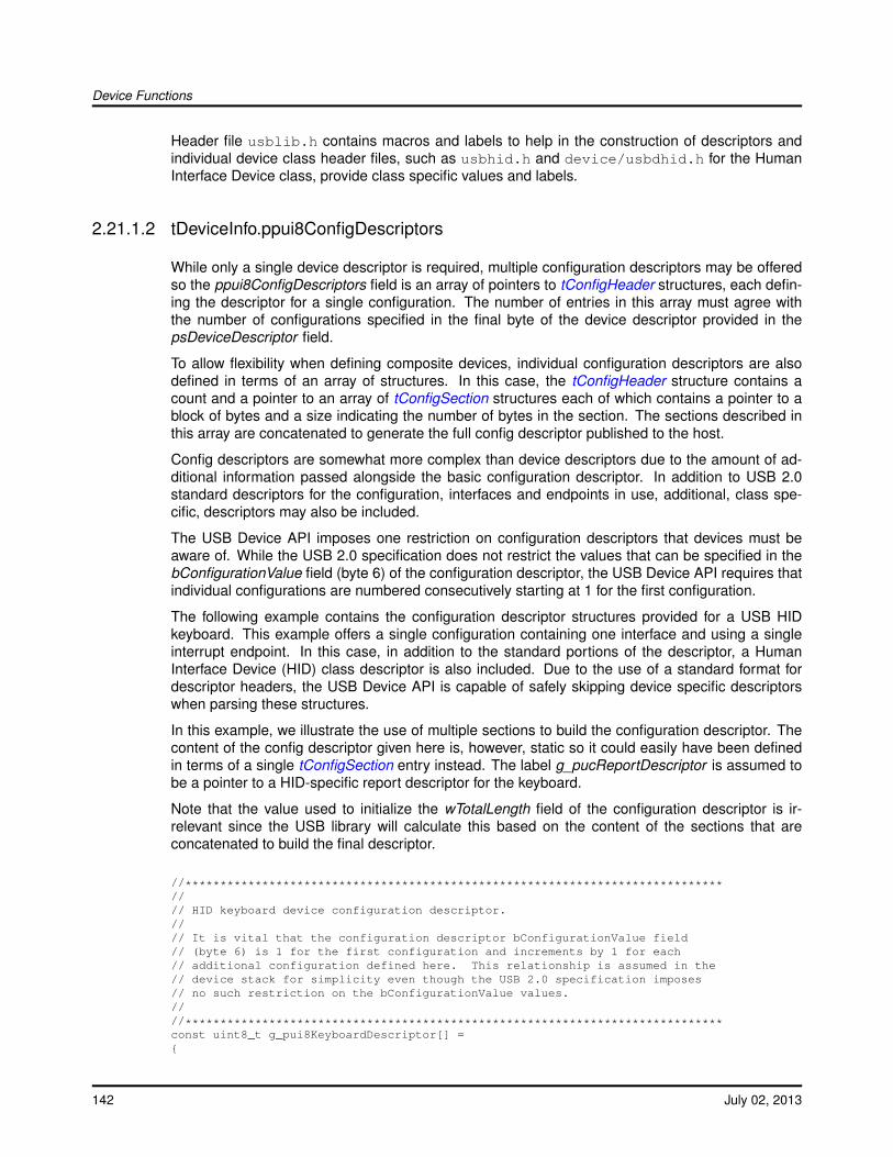
Device Functions
Header file usblib.h contains macros and labels to help in the construction of descriptors andindividual device class header files, such as usbhid.h and device/usbdhid.h for the HumanInterface Device class, provide class specific values and labels.
2.21.1.2 tDeviceInfo.ppui8ConfigDescriptors
While only a single device descriptor is required, multiple configuration descriptors may be offeredso the ppui8ConfigDescriptors field is an array of pointers to tConfigHeader structures, each defin-ing the descriptor for a single configuration. The number of entries in this array must agree withthe number of configurations specified in the final byte of the device descriptor provided in thepsDeviceDescriptor field.
To allow flexibility when defining composite devices, individual configuration descriptors are alsodefined in terms of an array of structures. In this case, the tConfigHeader structure contains acount and a pointer to an array of tConfigSection structures each of which contains a pointer to ablock of bytes and a size indicating the number of bytes in the section. The sections described inthis array are concatenated to generate the full config descriptor published to the host.
Config descriptors are somewhat more complex than device descriptors due to the amount of ad-ditional information passed alongside the basic configuration descriptor. In addition to USB 2.0standard descriptors for the configuration, interfaces and endpoints in use, additional, class spe-cific, descriptors may also be included.
The USB Device API imposes one restriction on configuration descriptors that devices must beaware of. While the USB 2.0 specification does not restrict the values that can be specified in thebConfigurationValue field (byte 6) of the configuration descriptor, the USB Device API requires thatindividual configurations are numbered consecutively starting at 1 for the first configuration.
The following example contains the configuration descriptor structures provided for a USB HIDkeyboard. This example offers a single configuration containing one interface and using a singleinterrupt endpoint. In this case, in addition to the standard portions of the descriptor, a HumanInterface Device (HID) class descriptor is also included. Due to the use of a standard format fordescriptor headers, the USB Device API is capable of safely skipping device specific descriptorswhen parsing these structures.
In this example, we illustrate the use of multiple sections to build the configuration descriptor. Thecontent of the config descriptor given here is, however, static so it could easily have been definedin terms of a single tConfigSection entry instead. The label g_pucReportDescriptor is assumed tobe a pointer to a HID-specific report descriptor for the keyboard.
Note that the value used to initialize the wTotalLength field of the configuration descriptor is ir-relevant since the USB library will calculate this based on the content of the sections that areconcatenated to build the final descriptor.
//*****************************************************************************//// HID keyboard device configuration descriptor.//// It is vital that the configuration descriptor bConfigurationValue field// (byte 6) is 1 for the first configuration and increments by 1 for each// additional configuration defined here. This relationship is assumed in the// device stack for simplicity even though the USB 2.0 specification imposes// no such restriction on the bConfigurationValue values.////*****************************************************************************const uint8_t g_pui8KeyboardDescriptor[] ={
142 July 02, 2013

Device Functions
//// Configuration descriptor header.//9, // Size of the configuration descriptor.USB_DTYPE_CONFIGURATION, // Type of this descriptor.USBShort(34), // The total size of this full structure
// (Value is patched by the USB library so is// not important here)
1, // The number of interfaces in this// configuration.
1, // The unique value for this configuration.5, // The string identifier that describes this
// configuration.USB_CONF_ATTR_SELF_PWR, // Bus Powered, Self Powered, remote wakeup.125, // The maximum power in 2mA increments.
};
//*****************************************************************************//// The interface and HID descriptors for the keyboard device.////*****************************************************************************uint8_t g_pui8HIDInterface[] ={
//// HID Device Class Interface Descriptor.//9, // Size of the interface descriptor.USB_DTYPE_INTERFACE, // Type of this descriptor.0, // The index for this interface.0, // The alternate setting for this interface.1, // The number of endpoints used by this
// interface.USB_CLASS_HID, // The interface classUSB_HID_SCLASS_BOOT, // The interface sub-class.USB_HID_PROTOCOL_KEYB, // The interface protocol for the sub-class
// specified above.4, // The string index for this interface.
//// HID Descriptor.//9, // Size of this HID descriptor.USB_HID_DTYPE_HID, // HID descriptor type.USBShort(0x101), // Version is 1.1.0, // Country code is not specified.1, // Number of descriptors.USB_HID_DTYPE_REPORT, // Type of this descriptor.USBShort(sizeof(g_pucReportDescriptor)),
// Length of the Descriptor.};
//*****************************************************************************//// The interrupt IN endpoint descriptor for the HID keyboard.////*****************************************************************************const uint8_t g_pui8HIDInEndpoint[] ={
//// Interrupt IN endpoint descriptor//7, // The size of the endpoint descriptor.USB_DTYPE_ENDPOINT, // Descriptor type is an endpoint.USB_EP_DESC_IN | USB_EP_TO_INDEX(INT_IN_ENDPOINT),USB_EP_ATTR_INT, // Endpoint is an interrupt endpoint.
July 02, 2013 143
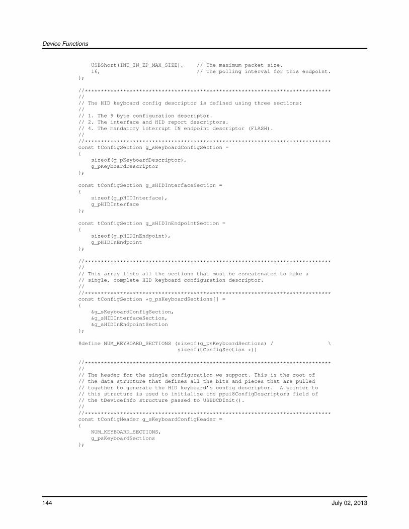
Device Functions
USBShort(INT_IN_EP_MAX_SIZE), // The maximum packet size.16, // The polling interval for this endpoint.
};
//*****************************************************************************//// The HID keyboard config descriptor is defined using three sections://// 1. The 9 byte configuration descriptor.// 2. The interface and HID report descriptors.// 4. The mandatory interrupt IN endpoint descriptor (FLASH).////*****************************************************************************const tConfigSection g_sKeyboardConfigSection ={
sizeof(g_pKeyboardDescriptor),g_pKeyboardDescriptor
};
const tConfigSection g_sHIDInterfaceSection ={
sizeof(g_pHIDInterface),g_pHIDInterface
};
const tConfigSection g_sHIDInEndpointSection ={
sizeof(g_pHIDInEndpoint),g_pHIDInEndpoint
};
//*****************************************************************************//// This array lists all the sections that must be concatenated to make a// single, complete HID keyboard configuration descriptor.////*****************************************************************************const tConfigSection *g_psKeyboardSections[] ={
&g_sKeyboardConfigSection,&g_sHIDInterfaceSection,&g_sHIDInEndpointSection
};
#define NUM_KEYBOARD_SECTIONS (sizeof(g_psKeyboardSections) / \sizeof(tConfigSection *))
//*****************************************************************************//// The header for the single configuration we support. This is the root of// the data structure that defines all the bits and pieces that are pulled// together to generate the HID keyboard’s config descriptor. A pointer to// this structure is used to initialize the ppui8ConfigDescriptors field of// the tDeviceInfo structure passed to USBDCDInit().////*****************************************************************************const tConfigHeader g_sKeyboardConfigHeader ={
NUM_KEYBOARD_SECTIONS,g_psKeyboardSections
};
144 July 02, 2013
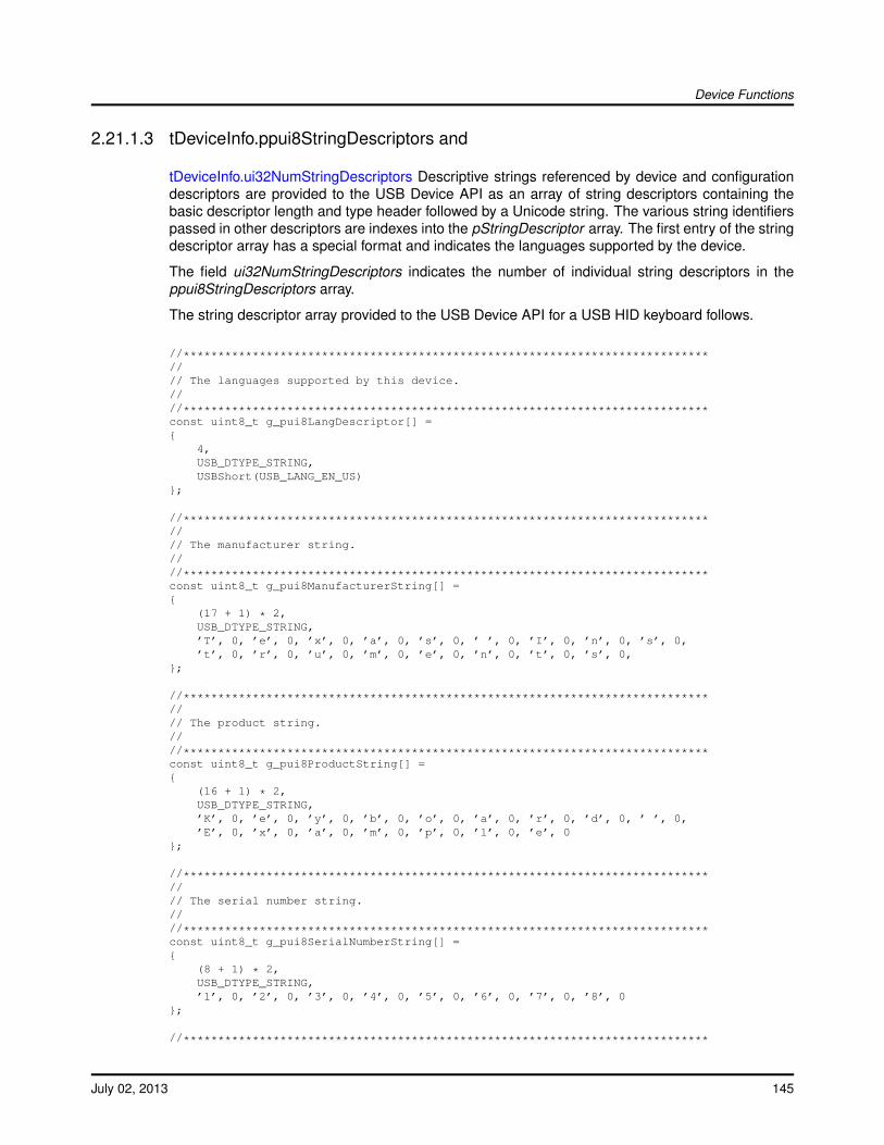
Device Functions
2.21.1.3 tDeviceInfo.ppui8StringDescriptors and
tDeviceInfo.ui32NumStringDescriptors Descriptive strings referenced by device and configurationdescriptors are provided to the USB Device API as an array of string descriptors containing thebasic descriptor length and type header followed by a Unicode string. The various string identifierspassed in other descriptors are indexes into the pStringDescriptor array. The first entry of the stringdescriptor array has a special format and indicates the languages supported by the device.
The field ui32NumStringDescriptors indicates the number of individual string descriptors in theppui8StringDescriptors array.
The string descriptor array provided to the USB Device API for a USB HID keyboard follows.
//****************************************************************************//// The languages supported by this device.////****************************************************************************const uint8_t g_pui8LangDescriptor[] ={
4,USB_DTYPE_STRING,USBShort(USB_LANG_EN_US)
};
//****************************************************************************//// The manufacturer string.////****************************************************************************const uint8_t g_pui8ManufacturerString[] ={
(17 + 1) * 2,USB_DTYPE_STRING,’T’, 0, ’e’, 0, ’x’, 0, ’a’, 0, ’s’, 0, ’ ’, 0, ’I’, 0, ’n’, 0, ’s’, 0,’t’, 0, ’r’, 0, ’u’, 0, ’m’, 0, ’e’, 0, ’n’, 0, ’t’, 0, ’s’, 0,
};
//****************************************************************************//// The product string.////****************************************************************************const uint8_t g_pui8ProductString[] ={
(16 + 1) * 2,USB_DTYPE_STRING,’K’, 0, ’e’, 0, ’y’, 0, ’b’, 0, ’o’, 0, ’a’, 0, ’r’, 0, ’d’, 0, ’ ’, 0,’E’, 0, ’x’, 0, ’a’, 0, ’m’, 0, ’p’, 0, ’l’, 0, ’e’, 0
};
//****************************************************************************//// The serial number string.////****************************************************************************const uint8_t g_pui8SerialNumberString[] ={
(8 + 1) * 2,USB_DTYPE_STRING,’1’, 0, ’2’, 0, ’3’, 0, ’4’, 0, ’5’, 0, ’6’, 0, ’7’, 0, ’8’, 0
};
//****************************************************************************
July 02, 2013 145
Device Functions
//// The array of string descriptors needed by the enumeration code.////****************************************************************************const uint8_t * const g_ppui8StringDescriptors[] ={
g_pui8LangDescriptor,g_pui8ManufacturerString,g_pui8ProductString,g_pui8SerialNumberString
};
In this example, the ppui8StringDescriptors member of the tDeviceInfo structure would be initializedwith the value g_ppui8StringDescriptors and the ui32NumStringDescriptors member would be setto the number of elements in the g_ppui8StringDescriptors array.
2.21.2 USB Event Handlers
The majority of the work in a USB device application will be carried out either in the context of,or in response to callbacks from the USB Device API. These callback functions are made avail-able to the USB Device API in the sCallbacks field of the tDeviceInfo structure passed in a call toUSBDCDInit().
Field sCallbacks is a structure of type tCustomHandlers which contains a function pointer for eachUSB event. The application must populate the table with valid function pointers for each event thatit wishes to be informed of. Setting any function pointer to NULL disables notification for that event.
The tCustomHandlers structure contains the following fields:
pfnGetDescriptor
pfnRequestHandler
pfnInterfaceChange
pfnConfigChange
pfnDataReceived
pfnDataSent
pfnResetHandler
pfnSuspendHandler
pfnResumeHandler
pfnDisconnectHandler
pfnEndpointHandler
pfnDeviceHandler
Note that all callbacks except the pfnDeviceHandler entry are made in interrupt context. It is,therefore, vital that handlers do not block or make calls to functions which cannot safely be madein an interrupt handler.
2.21.2.1 pfnGetDescriptor
Standard USB device, configuration and string descriptors are handled by the USB Device APIinternally but some device classes also define additional, class specific descriptors. In cases where
146 July 02, 2013
Device Functions
the host requests one of these non-standard descriptors, this callback is made to give the devicecode an opportunity to provide its own descriptor to satisfy the request.
If the device can satisfy the request, it must call USBDCDSendDataEP0() to provide the requesteddescriptor data to the host. If the request cannot be satisfied, the device should call USBDCD-StallEP0() to indicate that the descriptor request is not supported.
If this member of sCallbacks is set to NULL, the USB Device API will stall endpoint zero wheneverit receives a request for a non-standard descriptor.
2.21.2.2 pfnRequestHandler
The USB Device API contains handlers for all standard USB requests (as defined in Table 9-3 ofthe USB 2.0 specification) where a standard request is indicated by bits 5 and 6 of the requeststructure bmRequestType field being clear. If a request is received with a non-standard requesttype, this callback is made to give the device code an opportunity to satisfy the request.
The callback function receives a pointer to a standard, 8 byte request structure of type tUSBRe-quest containing information on the request type, the request identifier and various request-specificparameters. The structure also contains a length field, wLength, which indicates how much (if any)data will follow in the data stage of the USB transaction. Note that this data is not available atthe time the callback is made and the device code is responsible for requesting it using a call toUSBDCDRequestDataEP0() if required.
The sequence required when additional data is attached to the request is as follows:
Parse the request to determine the request type and verify that it is handled by the device. Ifnot, call USBDCDStallEP0() to indicate the problem.If the request is to be handled and wLength is non-zero, indicating that additional data isrequired, call USBDCDRequestDataEP0() passing a pointer to the buffer into which the datais to be written and the number of bytes of data to receive.Call USBDevEndpointDataAck() to acknowledge reception of the initial request transmission.This function is found in the Driver Library USB driver API.
Note that it is important to call USBDCDRequestDataEP0() prior to acknowledging the initial requestsince the acknowledgment frees the host to send the additional data. By making the calls in thisorder, the USB Device API is guaranteed to be in the correct state to receive the data when itarrives. Making the calls in the opposite order, creates a race condition which could result in lossof data.
Data received as a result of a call to USBDCDRequestDataEP0() will be delivered asynchronouslyvia the pfnDataReceived callback described below.
If this member of sCallbacks is set to NULL, the USB Device API will stall endpoint zero wheneverit receives a non-standard request.
2.21.2.3 pfnInterfaceChange
Based on the configuration descriptor published by the device code, several different alternate inter-face settings may be supported. In cases where the host wishes to change from the default interfaceconfiguration and the USB library determines that the requested alternate setting is supported, thiscallback is made to inform the device code of the change. The parameters passed provide the newalternate interface (ucAlternateSetting and the interface number (ucInterfaceNum).
July 02, 2013 147

Device Functions
This callback is only made once the USB Device API has validated the requested alternate setting.If the requested setting is not available in the published configuration descriptor, the USB DeviceAPI will stall endpoint zero to indicate the error to the host and make no callback to the device code.
If this member of sCallbacks is set to NULL, the USB Device API will note the interface changeinternally but not report it to the device code.
2.21.2.4 pfnConfigChange
When the host enumerates a device, it will ultimately select the configuration that is to be usedand send a SET_CONFIGURATION request to the device. When this occurs, the USB Device APIvalidates the configuration number passed against the device code’s published configuration de-scriptors then calls the pfnConfigChange callback to inform the device code of the configurationthat is to be used.
If this member of sCallbacks is set to NULL, the USB Device API will note the configuration changeinternally but not report it to the device code.
2.21.2.5 pfnDataReceived
This callback informs the device code of the arrival of data following an earlier call to USBDC-DRequestDataEP0(). On this callback, the received data will have been written into the bufferprovided to the USB Device API in the pucData parameter to USBDCDRequestDataEP0().
The callback handler does not need to acknowledge the data using a call to USBDevEndpoint-DataAck() in this case since this acknowledgment is performed within the USB Device API itself.
If this member of sCallbacks is set to NULL, the USB Device API will read endpoint zero datarequested via USBDCDRequestDataEP0() but not report its availability to the device code. De-vices making use of the USBDCDRequestDataEP0() call must, therefore, ensure that they supplya pfnDataReceived handler.
2.21.2.6 pfnDataSent
The USBDCDSendDataEP0() function allows device code to send an arbitrarily-sized block of datato the host via endpoint zero. The maximum packet size that can be sent via endpoint zero is,however, 64 bytes so larger blocks of data are sent in multiple packets. This callback function isused by the USB Device API to inform the device code when all data provided in the buffer passedto USBDCDSendDataEP0() has been consumed and scheduled for transmission to the host. Onreception of this callback, the device code is free to reuse the outgoing data buffer if required.
If this member of sCallbacks is set to NULL, the USB Device API will not inform the device codewhen a block of EP0 data is sent.
2.21.2.7 pfnResetHandler
The pfnResetHandler callback is made by the USB Device API whenever a bus reset is detected.This will typically occur during enumeration. The device code may use this notification to performany housekeeping required in preparation for a new configuration being set.
148 July 02, 2013
Device Functions
If this member of sCallbacks is set to NULL, the USB Device API will not inform the device codewhen a bus reset occurs.
2.21.2.8 pfnSuspendHandler
The pfnSuspendHandler callback is made whenever the USB Device API detects that suspendhas been signaled on the bus. Device code may make use of this notification to, for example, setappropriate power saving modes.
If this member of sCallbacks is set to NULL, the USB Device API will not inform the device codewhen a bus suspend occurs.
2.21.2.9 pfnResumeHandler
The pfnResumeHandler callback is made whenever the USB Device API detects that resume hasbeen signaled on the bus. Device code may make use of this notification to undo any changesmade in response to an earlier call to the pfnSuspendHandler callback.
If this member of sCallbacks is set to NULL, the USB Device API will not inform the device codewhen a bus resume occurs.
2.21.2.10 pfnDisconnectHandler
The pfnDisconnectHandler callback is made whenever the USB Device API detects that the devicehas been disconnected from the bus.
If this member of sCallbacks is set to NULL, the USB Device API will not inform the device codewhen a disconnection event occurs.
Note: The USB_EVENT_DISCONNECTED event will not be reported to the application if theMCU’s PB1/USB0VBUS pin is connected to a fixed +5 Volts rather than directly to the VBUS pin onthe USB connector or if the USB controller is configured to force device mode.
2.21.2.11 pfnEndpointHandler
While the use of endpoint zero is standardized and supported via several of the other callbacksalready listed (pfnDataSent , pfnDataReceived , pfnGetDescriptor , pfnRequestHandler , pfnInter-faceChange and pfnConfigChange), the use of other endpoints is entirely dependent upon thedevice class being implemented. The pfnEndpointHandler callback is, therefore, made to notifythe device code of all activity on any endpoint other than endpoint zero and it is the device code’sresponsibility to determine the correct action to take in response to each callback.
The ulStatus parameter passed to the handler provides information on the actual endpoint for whichthe callback is being made and allows the handler to determine if the event is due to transmission(if an IN endpoint event occurs) or reception (if an OUT endpoint event occurs) of data.
Having determined the endpoint sourcing the event, the device code can determine the actualevent by calling USBEndpointStatus() for the appropriate endpoint then clear the status by callingUSBDevEndpointStatusClear().
July 02, 2013 149
Device Functions
When incoming data is indicated by the flag USB_DEV_RX_PKT_RDY being set in the endpointstatus, data can be received using a call to USBEndpointDataGet() followed by a call to USBDe-vEndpointDataAck() to acknowledge the reception to the host.
When an event relating to an IN endpoint (data transmitted from the device to the host) is received,the status read from USBEndpointStatus() indicates any errors in transmission. If the value read is0, this implies that the data was successfully transmitted and acknowledged by the host.
Any device whose configuration descriptor indicates that it uses any endpoint (endpoint zero use isassumed) must populate the pfnEndpointHandler member of tCustomHandlers.
2.21.2.12 pfnDeviceHandler
Unlike the other calling functions pfnDeviceHandler specifies a generic input handler to the deviceclass. Callers of this function should check to insure that the class supports this entry by seeing ifthe pfnDeviceHandler is non-zero This call is provided to allow requests based on a given instanceto be passed into a device. This is commonly used by a top level composite device that is usingmultiple instances of the same class.
USB device classes that need to support being part of a composite device must imple-ment this function as the composite device class will need to call this function to in-form the class of interface, endpoint, and string index changes. See the documenta-tion on the USB_EVENT_COMP_IFACE_CHANGE, USB_EVENT_COMP_EP_CHANGE, andUSB_EVENT_COMP_STR_CHANGE.
2.21.3 Interrupt Vector Selection
An application using the USB Device API should normally ensure that the interrupt vector for thehardware USB controller is set to call function USB0DeviceIntHandler .
If the target application is intended to allow switching between USB device and USB host mode,however, this handler should be replaced with USB0DualModeIntHandler to allow the USB libraryto perform appropriate interrupt steering depending upon the current mode of operation. Hybridapplications must also call USBStackModeSet() to indicate the mode they wish to operate in.
2.21.4 Passing Control to the USB Device API
When all previous setup steps have been completed, control can be passed to the USB Device API.The library will enable the appropriate interrupts and connect the device to the bus in preparationfor enumeration by the USB host. This operation is initiated using a call to USBDCDInit() passingthe completed tDeviceInfo structure which describes the device.
Following this call, your device code callback functions will be called when USB events specific toyour device are detected by the library.
//// Pass the USB Device API our device information and connect the device to// the bus.//USBDCDInit(0, &g_sMouseDeviceInfo);
150 July 02, 2013

Device Functions
2.22 USB Device API Definitions
Data StructurestCompositeEntrytConfigHeadertConfigSectiontCustomHandlerstDeviceInfo
DefinesUSB_MAX_INTERFACES_PER_DEVICE
Functionsvoid USB0DeviceIntHandler (void)void USBDCDDeviceInfoInit (uint32_t ui32Index, tDeviceInfo ∗psDeviceInfo)void USBDCDInit (uint32_t ui32Index, tDeviceInfo ∗psDevice, void ∗pvDCDCBData)void USBDCDPowerStatusSet (uint32_t ui32Index, uint8_t ui8Power)bool USBDCDRemoteWakeupRequest (uint32_t ui32Index)void USBDCDRequestDataEP0 (uint32_t ui32Index, uint8_t ∗pui8Data, uint32_t ui32Size)void USBDCDSendDataEP0 (uint32_t ui32Index, uint8_t ∗pui8Data, uint32_t ui32Size)void USBDCDSetDefaultConfiguration (uint32_t ui32Index, uint32_t ui32DefaultConfig)void USBDCDStallEP0 (uint32_t ui32Index)void USBDCDTerm (uint32_t ui32Index)bool USBDeviceConfig (tDCDInstance ∗psDevInst, const tConfigHeader ∗psConfig)bool USBDeviceConfigAlternate (tDCDInstance ∗psDevInst, const tConfigHeader ∗psConfig,uint8_t ui8InterfaceNum, uint8_t ui8AlternateSetting)
2.22.1 Data Structure Documentation
2.22.1.1 tCompositeEntry
Definition:typedef struct{
const tDeviceInfo *psDevInfo;void *pvInstance;uint32_t ui32DeviceWorkspace;
}tCompositeEntry
Members:psDevInfo This is the top level device information structure.
July 02, 2013 151
Device Functions
pvInstance This is the instance data for the device structure.ui32DeviceWorkspace A per-device workspace used by the composite device.
Description:This type is used by an application to describe and instance of a device and an instance datapointer for that class. The psDevice pointer should be a pointer to a valid device class to includein the composite device. The pvInstance pointer should be a pointer to an instance pointer forthe device in the psDevice pointer.
2.22.1.2 tConfigHeader
Definition:typedef struct{
uint8_t ui8NumSections;const tConfigSection *const *psSections;
}tConfigHeader
Members:ui8NumSections The number of sections comprising the full descriptor for this configuration.psSections A pointer to an array of ui8NumSections section pointers which must be concate-
nated to form the configuration descriptor.
Description:This is the top level structure defining a USB device configuration descriptor. A configurationdescriptor contains a collection of device- specific descriptors in addition to the basic config,interface and endpoint descriptors. To allow flexibility in constructing the configuration, thedescriptor is described in terms of a list of data blocks. The first block must contain the con-figuration descriptor itself and the following blocks are appended to this in order to producethe full descriptor sent to the host in response to a GetDescriptor request for the configurationdescriptor.
2.22.1.3 tConfigSection
Definition:typedef struct{
uint16_t ui16Size;const uint8_t *pui8Data;
}tConfigSection
Members:ui16Size The number of bytes of descriptor data pointed to by pui8Data.pui8Data A pointer to a block of data containing an integral number of USB descriptors which
form part of a larger configuration descriptor.
Description:This structure defines a contiguous block of data which contains a group of descriptors thatform part of a configuration descriptor for a device. It is assumed that a config section containsonly whole descriptors. It is not valid to split a single descriptor across multiple sections.
152 July 02, 2013

Device Functions
2.22.1.4 tCustomHandlers
Definition:typedef struct{
tStdRequest pfnGetDescriptor;tStdRequest pfnRequestHandler;tInterfaceCallback pfnInterfaceChange;tInfoCallback pfnConfigChange;tInfoCallback pfnDataReceived;tInfoCallback pfnDataSent;tUSBIntHandler pfnResetHandler;tUSBIntHandler pfnSuspendHandler;tUSBIntHandler pfnResumeHandler;tUSBIntHandler pfnDisconnectHandler;tUSBEPIntHandler pfnEndpointHandler;tUSBDeviceHandler pfnDeviceHandler;
}tCustomHandlers
Members:pfnGetDescriptor This callback is made whenever the USB host requests a non-standard
descriptor from the device.pfnRequestHandler This callback is made whenever the USB host makes a non-standard
request.pfnInterfaceChange This callback is made in response to a SetInterface request from the
host.pfnConfigChange This callback is made in response to a SetConfiguration request from the
host.pfnDataReceived This callback is made when data has been received following to a call to
USBDCDRequestDataEP0.pfnDataSent This callback is made when data has been transmitted following a call to USB-
DCDSendDataEP0.pfnResetHandler This callback is made when a USB reset is detected.pfnSuspendHandler This callback is made when the bus has been inactive long enough to
trigger a suspend condition.pfnResumeHandler This is called when resume signaling is detected.pfnDisconnectHandler This callback is made when the device is disconnected from the USB
bus.pfnEndpointHandler This callback is made to inform the device of activity on all endpoints
other than endpoint zero.pfnDeviceHandler This generic handler is provided to allow requests based on a given in-
stance to be passed into a device. This is commonly used by a top level composite devicethat is using multiple instances of a class.
Description:USB event handler functions used during enumeration and operation of the device stack.
July 02, 2013 153
Device Functions
2.22.1.5 tDeviceInfo
Definition:typedef struct{
const tCustomHandlers *psCallbacks;const uint8_t *pui8DeviceDescriptor;const tConfigHeader *const *ppsConfigDescriptors;const uint8_t *const *ppui8StringDescriptors;uint32_t ui32NumStringDescriptors;
}tDeviceInfo
Members:psCallbacks A pointer to a structure containing pointers to event handler functions provided
by the client to support the operation of this device.pui8DeviceDescriptor A pointer to the device descriptor for this device.ppsConfigDescriptors A pointer to an array of configuration descriptor pointers. Each entry
in the array corresponds to one configuration that the device may be set to use by the USBhost. The number of entries in the array must match the bNumConfigurations value in thedevice descriptor array, pui8DeviceDescriptor.
ppui8StringDescriptors A pointer to the string descriptor array for this device. This arraymust be arranged as follows:HASH(0x10498318)and so on.
ui32NumStringDescriptors The total number of descriptors provided in the ppStringDescrip-tors array.
Description:This structure is passed to the USB library on a call to USBDCDInit and provides the library withinformation about the device that the application is implementing. It contains functions pointersfor the various USB event handlers and pointers to each of the standard device descriptors.
2.22.2 Define Documentation
2.22.2.1 USB_MAX_INTERFACES_PER_DEVICE
Definition:#define USB_MAX_INTERFACES_PER_DEVICE
Description:The maximum number of independent interfaces that any single device implementation cansupport. Independent interfaces means interface descriptors with different bInterfaceNumbervalues - several interface descriptors offering different alternative settings but the same inter-face number count as a single interface.
154 July 02, 2013
Device Functions
2.22.3 Function Documentation
2.22.3.1 USB0DeviceIntHandler
The USB device interrupt handler.
Prototype:voidUSB0DeviceIntHandler(void)
Description:This the main USB interrupt handler entry point for use in USB device applications. Thistop-level handler will branch the interrupt off to the appropriate application or stack handlersdepending on the current status of the USB controller.
Applications which operate purely as USB devices (rather than dual mode applications whichcan operate in either device or host mode at different times) must ensure that a pointer to thisfunction is installed in the interrupt vector table entry for the USB0 interrupt. For dual modeoperation, the vector should be set to point to USB0DualModeIntHandler() instead.
Returns:None.
2.22.3.2 USBDCDDeviceInfoInit
Initialize an instance of the tDeviceInfo structure.
Prototype:voidUSBDCDDeviceInfoInit(uint32_t ui32Index,
tDeviceInfo *psDeviceInfo)
Parameters:ui32Index is the index of the USB controller which is to be initialized.psDeviceInfo is a pointer to the tDeviceInfo structure that needs to be initialized. This function
must be called by a USB device class instance to initialize the basic tDeviceInfo requiredfor all USB device class modules. This is typically called in the initialization routine forUSB device class. For example in usbdaudio.c that supports USB device audio classes,this function is called in the USBDAudioCompositeInit() function which is used for bothcomposite and non-composites instances of the USB audio class.
Note:This function should not be called directly by applications.
Returns:None.
2.22.3.3 void USBDCDInit (uint32_t ui32Index, tDeviceInfo ∗ psDevice, void ∗pvDCDCBData)
Initialize the USB library device control driver for a given hardware controller.
July 02, 2013 155
Device Functions
Parameters:ui32Index is the index of the USB controller which is to be initialized.psDevice is a pointer to a structure containing information that the USB library requires to
support operation of this application’s device. The structure contains event handler call-backs and pointers to the various standard descriptors that the device wishes to publish tothe host.
pvDCDCBData is the callback data for any device callbacks.
Description:This function must be called by a device class which wishes to operate as a USB device andis not typically called by an application. This function initializes the USB device control driverfor the given controller and saves the device information for future use. Prior to returning fromthis function, the device is connected to the USB bus. Following return, the caller can expectto receive a callback to the supplied pfnResetHandler function when a host connects to thedevice. The pvDCDCBData contains a pointer to data that is returned with the DCD calls backto the function in the psDevice->psCallbacks() functions.
The device information structure passed in psDevice must remain unchanged between this calland any matching call to USBDCDTerm() because it is not copied by the USB library.
The USBStackModeSet() function can be called with eUSBModeForceDevice in order to causethe USB library to force the USB operating mode to a device controller. This allows the applica-tion to used the USBVBUS and USBID pins as GPIOs on devices that support forcing OTG tooperate as a device only controller. By default the USB library will assume that the USBVBUSand USBID pins are configured as USB pins and not GPIOs.
Returns:None.
2.22.3.4 USBDCDPowerStatusSet
Reports the device power status (bus- or self-powered) to the library.
Prototype:voidUSBDCDPowerStatusSet(uint32_t ui32Index,
uint8_t ui8Power)
Parameters:ui32Index is the index of the USB controller whose device power status is being reported.ui8Power indicates the current power status, either USB_STATUS_SELF_PWR or
USB_STATUS_BUS_PWR.
Description:Applications which support switching between bus- or self-powered operation should call thisfunction whenever the power source changes to indicate the current power status to the USBlibrary. This information is required by the library to allow correct responses to be providedwhen the host requests status from the device.
Returns:None.
156 July 02, 2013

Device Functions
2.22.3.5 USBDCDRemoteWakeupRequest
Requests a remote wake up to resume communication when in suspended state.
Prototype:boolUSBDCDRemoteWakeupRequest(uint32_t ui32Index)
Parameters:ui32Index is the index of the USB controller that will request a bus wake up.
Description:When the bus is suspended, an application which supports remote wake up (advertised to thehost via the configuration descriptor) may call this function to initiate remote wake up signalingto the host. If the remote wake up feature has not been disabled by the host, this will causethe bus to resume operation within 20mS. If the host has disabled remote wake up, false willbe returned to indicate that the wake up request was not successful.
Returns:Returns true if the remote wake up is not disabled and the signaling was started or false ifremote wake up is disabled or if signaling is currently ongoing following a previous call to thisfunction.
2.22.3.6 USBDCDRequestDataEP0
This function starts the request for data from the host on endpoint zero.
Prototype:voidUSBDCDRequestDataEP0(uint32_t ui32Index,
uint8_t *pui8Data,uint32_t ui32Size)
Parameters:ui32Index is the index of the USB controller from which the data is being requested.pui8Data is a pointer to the buffer to fill with data from the USB host.ui32Size is the size of the buffer or data to return from the USB host.
Description:This function handles retrieving data from the host when a custom command has been is-sued on endpoint zero. If the application needs notification when the data has been received,psCallbacks->pfnDataReceived() in the tDeviceInfo structure must contain valid func-tion pointer. In nearly all cases this is necessary because the caller of this function would likelyneed to know that the data requested was received.
Returns:None.
2.22.3.7 USBDCDSendDataEP0
This function requests transfer of data to the host on endpoint zero.
July 02, 2013 157

Device Functions
Prototype:voidUSBDCDSendDataEP0(uint32_t ui32Index,
uint8_t *pui8Data,uint32_t ui32Size)
Parameters:ui32Index is the index of the USB controller which is to be used to send the data.pui8Data is a pointer to the buffer to send via endpoint zero.ui32Size is the amount of data to send in bytes.
Description:This function handles sending data to the host when a custom command is issued or non-standard descriptor has been requested on endpoint zero. If the application needs notificationwhen this is complete, psCallbacks->pfnDataSent in the tDeviceInfo structure must con-tain a valid function pointer. This callback could be used to free up the buffer passed intothis function in the pui8Data parameter. The contents of the pui8Data buffer must remainunchanged until the pfnDataSent callback is received.
Returns:None.
2.22.3.8 USBDCDSetDefaultConfiguration
This function sets the default configuration for the device.
Prototype:voidUSBDCDSetDefaultConfiguration(uint32_t ui32Index,
uint32_t ui32DefaultConfig)
Parameters:ui32Index is the index of the USB controller whose default configuration is to be set.ui32DefaultConfig is the configuration identifier (byte 6 of the standard configuration descrip-
tor) which is to be presented to the host as the default configuration in cases where theconfiguration descriptor is queried prior to any specific configuration being set.
Description:This function allows a device to override the default configuration descriptor that will be returnedto a host whenever it is queried prior to a specific configuration having been set. The parameterpassed must equal one of the configuration identifiers found in the ppsConfigDescriptorsarray for the device.
If this function is not called, the USB library will return the first configuration in theppsConfigDescriptors array as the default configuration.
Note:The USB device stack assumes that the configuration IDs (byte 6 of the configura-tion descriptor, bConfigurationValue) stored within the configuration descriptor array,ppsConfigDescriptors, are equal to the array index + 1. In other words, the first entryin the array must contain a descriptor with bConfigurationValue 1, the second must havebConfigurationValue 2 and so on.
158 July 02, 2013

Device Functions
Returns:None.
2.22.3.9 USBDCDStallEP0
This function generates a stall condition on endpoint zero.
Prototype:voidUSBDCDStallEP0(uint32_t ui32Index)
Parameters:ui32Index is the index of the USB controller whose endpoint zero is to be stalled.
Description:This function is typically called to signal an error condition to the host when an unsupportedrequest is received by the device. It should be called from within the callback itself (in interruptcontext) and not deferred until later since it affects the operation of the endpoint zero statemachine in the USB library.
Returns:None.
2.22.3.10 USBDCDTerm
Free the USB library device control driver for a given hardware controller.
Prototype:voidUSBDCDTerm(uint32_t ui32Index)
Parameters:ui32Index is the index of the USB controller which is to be freed.
Description:This function should be called by an application if it no longer requires the use of a given USBcontroller to support its operation as a USB device. It frees the controller for use by anotherclient.
It is the caller’s responsibility to remove its device from the USB bus prior to calling this function.
Returns:None.
2.22.3.11 USBDeviceConfig
Configure the USB controller appropriately for the device whose configuration descriptor is passed.
July 02, 2013 159
Device Functions
Prototype:boolUSBDeviceConfig(tDCDInstance *psDevInst,
const tConfigHeader *psConfig)
Parameters:psDevInst is a pointer to the device instance being configured.psConfig is a pointer to the configuration descriptor that the USB controller is to be set up to
support.
Description:This function may be used to initialize a USB controller to operate as the device whose con-figuration descriptor is passed. The function enables the USB controller, partitions the FIFOappropriately and configures each endpoint required by the configuration. If the supplied con-figuration supports multiple alternate settings for any interface, the USB FIFO is set up as-suming the worst case use (largest packet size for a given endpoint in any alternate settingusing that endpoint) to allow for on-the-fly alternate setting changes later. On return from thisfunction, the USB controller is configured for correct operation of the default configuration ofthe device described by the descriptor passed.
USBDCDConfig() is an optional call and applications may chose to make direct calls toSysCtlPeripheralEnable(), SysCtlUSBPLLEnable(), USBDevEndpointConfigSet() and USBFI-FOConfigSet() instead of using this function. If this function is used, it must be called priorto USBDCDInit() since this call assumes that the low level hardware configuration has beencompleted before it is made.
Returns:Returns true on success or false on failure.
2.22.3.12 USBDeviceConfigAlternate
Configure the affected USB endpoints appropriately for one alternate interface setting.
Prototype:boolUSBDeviceConfigAlternate(tDCDInstance *psDevInst,
const tConfigHeader *psConfig,uint8_t ui8InterfaceNum,uint8_t ui8AlternateSetting)
Parameters:psDevInst is a pointer to the device instance being configured.psConfig is a pointer to the configuration descriptor that contains the interface whose alter-
nate settings is to be configured.ui8InterfaceNum is the number of the interface whose alternate setting is to be configured.
This number corresponds to the bInterfaceNumber field in the desired interface descriptor.ui8AlternateSetting is the alternate setting number for the desired interface. This number
corresponds to the bAlternateSetting field in the desired interface descriptor.
Description:This function may be used to reconfigure the endpoints of an interface for operation in oneof the interface’s alternate settings. Note that this function assumes that the endpoint FIFO
160 July 02, 2013

Device Functions
settings will not need to change and only the endpoint mode is changed. This assumption isvalid if the USB controller was initialized using a previous call to USBDCDConfig().
In reconfiguring the interface endpoints, any additional configuration bits set in the endpointconfiguration other than the direction (USB_EP_DEV_IN or USB_EP_DEV_OUT) and mode(USB_EP_MODE_MASK) are preserved.
Returns:Returns true on success or false on failure.
July 02, 2013 161

Device Functions
162 July 02, 2013

Host Functions
3 Host FunctionsIntroduction . . . . . . . . . . . . . . . . . . . . . . . . . . . . . . . . . . . . . . . . . . . . . . . . . . . . . . . . . . . . . . . . . . . . . . . . . . . . . . . . . . . . . . . . . . . . .163Host Controller Driver . . . . . . . . . . . . . . . . . . . . . . . . . . . . . . . . . . . . . . . . . . . . . . . . . . . . . . . . . . . . . . . . . . . . . . . . . . . . . . . . . . . 165Host Controller Driver Definitions . . . . . . . . . . . . . . . . . . . . . . . . . . . . . . . . . . . . . . . . . . . . . . . . . . . . . . . . . . . . . . . . . . . . . . . .167Host Class Driver . . . . . . . . . . . . . . . . . . . . . . . . . . . . . . . . . . . . . . . . . . . . . . . . . . . . . . . . . . . . . . . . . . . . . . . . . . . . . . . . . . . . . . . 184Host Class Driver Definitions . . . . . . . . . . . . . . . . . . . . . . . . . . . . . . . . . . . . . . . . . . . . . . . . . . . . . . . . . . . . . . . . . . . . . . . . . . . .195Host Device Interface . . . . . . . . . . . . . . . . . . . . . . . . . . . . . . . . . . . . . . . . . . . . . . . . . . . . . . . . . . . . . . . . . . . . . . . . . . . . . . . . . . . 219Host Device Interface Definitions . . . . . . . . . . . . . . . . . . . . . . . . . . . . . . . . . . . . . . . . . . . . . . . . . . . . . . . . . . . . . . . . . . . . . . . . 221Host Programming Examples . . . . . . . . . . . . . . . . . . . . . . . . . . . . . . . . . . . . . . . . . . . . . . . . . . . . . . . . . . . . . . . . . . . . . . . . . . . 226
3.1 Introduction
This chapter covers the support provided by the USB library for the USB controller in host mode.In order to simplify the application and the addition of new devices and device classes, the USBlibrary provides a layered interface to the USB host controller. At the top layer of the USB librarythere are application interfaces that provide easy access to the various types of peripherals that aresupported by the USB library. Below this layer are the USB host controller’s device interfaces thathandle the specifics of each type of device and how to communicate with the USB host class driver.The USB host class drivers handle the basics of dealing with whole classes of devices like HID andMass Storage Class devices. The USB host class driver layer communicates with the lowest level ofthe USB library which is the USB host controller driver. This lowest level directly accesses DriverLibfunctions to provide communications with the USB device that is connected. This communication isprovided by callbacks or direct APIs that is discussed in the rest of this chapter. Much like the USBlibrary’s device programming interface, the host interface has the following layers:
Device APIs (Mouse, Keyboard, Filesystem)
USB Class Driver APIs (HID, Mass Storage, Hub)
USB Host Controller APIs
DriverLib USB Driver APIs
July 02, 2013 163
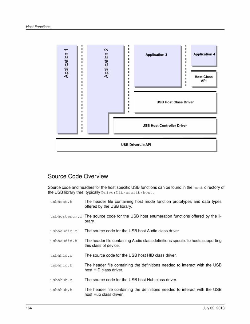
Host Functions
USB Host Controller Driver
USB DriverLib API
USB Host Class Driver
Host ClassAPI
App
licat
ion
1
App
licat
ion
2
Application 3 Application 4
Source Code Overview
Source code and headers for the host specific USB functions can be found in the host directory ofthe USB library tree, typically DriverLib/usblib/host.
usbhost.h The header file containing host mode function prototypes and data typesoffered by the USB library.
usbhostenum.c The source code for the USB host enumeration functions offered by the li-brary.
usbhaudio.c The source code for the USB host Audio class driver.
usbhaudio.h The header file containing Audio class definitions specific to hosts supportingthis class of device.
usbhhid.c The source code for the USB host HID class driver.
usbhhid.h The header file containing the definitions needed to interact with the USBhost HID class driver.
usbhhub.c The source code for the USB host Hub class driver.
usbhhub.h The header file containing the definitions needed to interact with the USBhost Hub class driver.
164 July 02, 2013
Host Functions
usbhhidkeyboard.cThe source code for the USB host HID class keyboard device.
usbhhidkeyboard.hThe header file containing the definitions needed to interact with the USBhost HID class keyboard device.
usbhhidmouse.cThe source code for the USB host HID class mouse device.
usbhhidmouse.hThe header file containing the definitions needed to interact with the USBhost HID class mouse device.
usbhmsc.c The source code for the USB host Mass Storage class driver.
usbhmsc.h The header file containing Mass Storage class definitions specific to hostssupporting this class of device.
usbhscsi.c The source code for a high level SCSI interface which calls the host MassStorage class driver.
3.2 Host Controller Driver
The USB library host controller driver provides an interface to the host controller’s hardware registerinterface. This is the lowest level of the driver interface and it interacts directly with the DriverLibUSB APIs. The host controller driver provides all of the functionality necessary to provide enumer-ation of devices regardless of the type of device that is connected. This portion of the enumerationcode only enumerates the device and allows the higher level drivers to actually handle normal de-vice operations. To allow the application to conserve code and data memory, the host controllerdriver provides a method to allow applications to only include the host class drivers that are neededfor each type of USB device. This allows an application to handle multiple classes of devices butonly include the USB library code that the application needs to communicate with the devices thatthe application supports. While the host controller driver handles the enumeration of devices it re-lies on USB pipes, that are allocated by the higher level class drivers, as the direct communicationsmethod with a devices end points.
3.2.1 Enumeration
The USB host controller driver handles all of the details necessary to discover and enumerate anyUSB device. The USB host controller driver only performs enumeration and relies on the host classdrivers to perform any other communications with USB devices including the allocation of the end-points for the device. Most of the code used to enumerate devices is run in interrupt context and iscontained in the enumeration handler. In order to complete the enumeration process, the host con-troller driver also requires that the application periodically call the USBHCDMain() function. Whena host class driver or an application needs access to endpoint 0 of a device, it uses the USBHCD-ControlTransfer() interface to send data to the device or receive data from the device. During the
July 02, 2013 165

Host Functions
enumeration process the host controller driver searches a list of host class drivers provided by theapplication in the USBHCDRegisterDrivers() call. The details of this structure are covered in thehost class drivers section of this document. If the host controller driver finds a host class driver thatmatches the class of the enumerated device, it calls the open function for that host class driver. If nohost class driver is found the host controller driver ignores the device and there is no notification tothe application. The host controller driver or the host class driver can provide callbacks up throughthe USB library to inform the application of enumeration events. The host class drivers are respon-sible for configuring the USB pipes based on the type of device that is discovered. The applicationis notified of events in two ways: one is from the host class driver for the connected device and theother is from a non-device specific event driver. The class specific events come from the host classdriver, while the generic connection, power and other non-device class specific events come fromthe host event driver if it is included in the application. The section "USB Events Driver" covers thehost events driver, the valid events and how to include the host events driver in an application.
3.2.2 USB Pipes
The host controller driver layer uses interfaces called USB pipes as the primary method of commu-nications with USB devices. These USB pipes can be dynamically allocated or statically allocatedby the USB class drivers during enumeration. The USB pipes are usually only used within theUSB library or by host class drivers and are not usually directly accessed by applications. The USBpipes are allocated and freed by calling the USBHCDPipeAlloc() and USBHCDPipeFree() functionsand are initially configured by calling the USBHCDPipeConfig(). The USBHCDPipeAlloc() and US-BHCDPipeConfig() functions are used during USB device enumeration to allocate USB pipes tospecific endpoints of the USB device. On disconnect, the USBHCDPipeFree() function is calledto free up the USB pipe for use by a new USB device. While in use, the USB pipes can providestatus and perform read and write operations. Calling USBHCDPipeStatus() allows a host classdriver to check the status of a pipe. However most access to the USB pipes occurs through USB-HCDPipeWrite() and USBHCDPipeRead() and the callback function provided when the USB pipewas allocated. These are used to read or write to endpoints on USB devices on endpoints otherthan the control endpoint on endpoint 0. Since endpoint 0 is shared with all devices, the host con-troller interface does not use USB pipes for communications over endpoint 0 and instead uses theUSBHCDControlTransfer() function.
3.2.3 Control Transactions
All USB control transactions are handled through the USBHCDControlTransfer() function. Thisfunction is primarily used inside the host controller driver itself during enumeration, however somedevices may require using control transactions through endpoint 0. The HID class drivers are agood example of a USB class driver that uses control transactions to send data to a USB device.The USBHCDControlTransfer() function should not be called from within interrupt context as controltransfers are a blocking operation that relies on interrupts to proceed. Since most callbacks occurin interrupt context, any calls to USBHCDControlTransfer() should be deferred until running outsidethe callback event. The USB host HID keyboard example is a good example of performing a controltransaction outside of a callback function.
166 July 02, 2013
Host Functions
3.2.4 Interrupt Handling
All interrupt handling is done by the USB library host controller driver and most callbacks are donein interrupt context and like interrupt handlers should defer any real processing of events to occuroutside the interrupt context. The callbacks are used to notify the upper layers of events that occurduring enumeration or during normal operation. Because most of enumeration code is handled byinterrupt handlers the enumeration code does require that the application call the USBHCDMain()function in order to progress through the enumeration states without running all code in interruptcontext.
3.3 Host Controller Driver Definitions
Data StructurestUSBHostClassDriver
DefinesDECLARE_EVENT_DRIVER(VarName, pfnOpen, pfnClose, pfnEvent)
Functionsvoid USB0HostIntHandler (void)uint32_t USBHCDControlTransfer (uint32_t ui32Index, tUSBRequest ∗psSetupPacket, tUSB-HostDevice ∗psDevice, uint8_t ∗pui8Data, uint32_t ui32Size, uint32_t ui32MaxPacketSize)uint8_t USBHCDDevAddress (uint32_t ui32Instance)uint8_t USBHCDDevClass (uint32_t ui32Instance, uint32_t ui32Interface)uint8_t USBHCDDevHubPort (uint32_t ui32Instance)uint8_t USBHCDDevProtocol (uint32_t ui32Instance, uint32_t ui32Interface)uint8_t USBHCDDevSubClass (uint32_t ui32Instance, uint32_t ui32Interface)int32_t USBHCDEventDisable (uint32_t ui32Index, void ∗pvEventDriver, uint32_t ui32Event)int32_t USBHCDEventEnable (uint32_t ui32Index, void ∗pvEventDriver, uint32_t ui32Event)void USBHCDInit (uint32_t ui32Index, void ∗pvPool, uint32_t ui32PoolSize)void USBHCDMain (void)uint32_t USBHCDPipeAlloc (uint32_t ui32Index, uint32_t ui32EndpointType, tUSBHostDevice∗psDevice, tHCDPipeCallback pfnCallback)uint32_t USBHCDPipeAllocSize (uint32_t ui32Index, uint32_t ui32EndpointType, tUSBHost-Device ∗psDevice, uint32_t ui32Size, tHCDPipeCallback pfnCallback)uint32_t USBHCDPipeConfig (uint32_t ui32Pipe, uint32_t ui32MaxPayload, uint32_tui32Interval, uint32_t ui32TargetEndpoint)void USBHCDPipeDataAck (uint32_t ui32Pipe)void USBHCDPipeFree (uint32_t ui32Pipe)uint32_t USBHCDPipeRead (uint32_t ui32Pipe, uint8_t ∗pui8Data, uint32_t ui32Size)uint32_t USBHCDPipeReadNonBlocking (uint32_t ui32Pipe, uint8_t ∗pui8Data, uint32_tui32Size)
July 02, 2013 167
Host Functions
uint32_t USBHCDPipeSchedule (uint32_t ui32Pipe, uint8_t ∗pui8Data, uint32_t ui32Size)uint32_t USBHCDPipeStatus (uint32_t ui32Pipe)uint32_t USBHCDPipeWrite (uint32_t ui32Pipe, uint8_t ∗pui8Data, uint32_t ui32Size)uint32_t USBHCDPowerAutomatic (uint32_t ui32Index)uint32_t USBHCDPowerConfigGet (uint32_t ui32Index)void USBHCDPowerConfigInit (uint32_t ui32Index, uint32_t ui32PwrConfig)uint32_t USBHCDPowerConfigSet (uint32_t ui32Index, uint32_t ui32Config)void USBHCDRegisterDrivers (uint32_t ui32Index, const tUSBHostClassDriver ∗const∗ppsHClassDrvs, uint32_t ui32NumDrivers)void USBHCDReset (uint32_t ui32Index)void USBHCDResume (uint32_t ui32Index)void USBHCDSetAddress (uint32_t ui32DevIndex, uint32_t ui32DevAddress)void USBHCDSetConfig (uint32_t ui32Index, uint32_t ui32Device, uint32_t ui32Configuration)void USBHCDSetInterface (uint32_t ui32Index, uint32_t ui32Device, uint32_t ui32Interface,uint32_t ui32AltSetting)void USBHCDSuspend (uint32_t ui32Index)void USBHCDTerm (uint32_t ui32Index)
3.3.1 Detailed Description
The macros and functions defined in this section can be found in header file host/usbhost.h.
3.3.2 Data Structure Documentation
3.3.2.1 tUSBHostClassDriver
Definition:typedef struct{
uint32_t ui32InterfaceClass;void * (*pfnOpen)(tUSBHostDevice *psDevice);void (*pfnClose)(void *pvInstance);void (*pfnIntHandler)(void *pvInstance);
}tUSBHostClassDriver
Members:ui32InterfaceClass The interface class that this device class driver supports.pfnOpen The function is called when this class of device has been detected.pfnClose The function is called when the device, originally opened with a call to the pfnOpen
function, is disconnected.pfnIntHandler This is the optional interrupt handler that will be called when an endpoint asso-
ciated with this device instance generates an interrupt.
Description:This structure defines a USB host class driver interface, it is parsed to find a USB class driveronce a USB device is enumerated.
168 July 02, 2013

Host Functions
3.3.3 Define Documentation
3.3.3.1 DECLARE_EVENT_DRIVER
This macro is used to declare an instance of an Event driver for the USB library.
Definition:#define DECLARE_EVENT_DRIVER(VarName,
pfnOpen,pfnClose,pfnEvent)
Parameters:VarName is the name of the variable.pfnOpen is the callback for the Open call to this driver. This value is currently reserved and
should be set to 0.pfnClose is the callback for the Close call to this driver. This value is currently reserved and
should be set to 0.pfnEvent is the callback that will be called for various USB events.
Description:The first parameter is the actual name of the variable that will be declared by this macro. Thesecond and third parameter are reserved for future functionality and are unused and should beset to zero. The last parameter is the actual callback function and is specified as a functionpointer of the type:
void (∗pfnEvent)(void ∗pvData);
When the pfnEvent function is called the void pointer that is passed in as a parameter shouldbe cast to a pointer to a structure of type tEventInfo. This will contain the event that caused thepfnEvent function to be called.
3.3.4 Function Documentation
3.3.4.1 void USB0HostIntHandler (void)
The USB host mode interrupt handler for controller index 0.
This the main USB interrupt handler entry point. This handler will branch the interrupt off to theappropriate handlers depending on the current status of the USB controller. This function mustbe placed in the interrupt table in order for the USB Library host stack to function.
Returns:None.
3.3.4.2 USBHCDControlTransfer
Definition:uint32_t USBHCDControlTransfer (uint32_t ui32Index , tUSBRequest
*psSetupPacket , tUSBHostDevice *psDevice , uint8_t *pui8Data ,uint32_t ui32Size , uint32_t ui32MaxPacketSize )
July 02, 2013 169
Host Functions
Description:This function completes a control transaction to a device.
Parameters:ui32Index is the controller index to use for this transfer.psSetupPacket is the setup request to be sent.psDevice is the device instance pointer for this request.pui8Data is the data to send for OUT requests or the receive buffer for IN requests.ui32Size is the size of the buffer in pui8Data.ui32MaxPacketSize is the maximum packet size for the device for this request.
This function handles the state changes necessary to send a control transaction to a device.This function should not be called from within an interrupt callback as it is a blocking function.
Returns:The number of bytes of data that were sent or received as a result of this request.
3.3.4.3 USBHCDDevAddress
Definition:uint8_t USBHCDDevAddress (uint32_t ui32Instance )
Description:This function will return the USB address for the requested device instance.
Parameters:ui32Instance is a unique value indicating which device to query.
This function returns the USB address for the device that is associated with the ui32Instanceparameter. The caller must use a value for ui32Instance have been passed to the applica-tion when it receives a USB_EVENT_CONNECTED event. The function will return the USBaddress for the interface number specified by the ui32Interface parameter.
Returns:The USB address for the requested interface.
3.3.4.4 USBHCDDevClass
Definition:uint8_t USBHCDDevClass (uint32_t ui32Instance , uint32_t
ui32Interface )
Description:This function will return the USB class for the requested device instance.
Parameters:ui32Instance is a unique value indicating which device to query.ui32Interface is the interface number to query for the USB class.
This function returns the USB class for the device that is associated with the ui32Instanceparameter. The caller must use a value for ui32Instance have been passed to the applicationwhen it receives a USB_EVENT_CONNECTED event. The function will return the USB class
170 July 02, 2013

Host Functions
for the interface number specified by the ui32Interface parameter. If ui32Interface is set to0xFFFFFFFF then the function will return the USB class for the first interface that is found inthe device’s USB descriptors.
Returns:The USB class for the requested interface.
3.3.4.5 USBHCDDevHubPort
Definition:uint8_t USBHCDDevHubPort (uint32_t ui32Instance )
Description:This function returns the USB hub port for the requested device instance.
Parameters:ui32Instance is a unique value indicating which device to query.
This function returns the USB hub port for the device that is associated with the ui32Instanceparameter. The caller must use the value for ui32Instance was passed to the application whenit receives a USB_EVENT_CONNECTED event. The function returns the USB hub port for theinterface number specified by the ui32Interface parameter.
Returns:The USB hub port for the requested interface.
3.3.4.6 USBHCDDevProtocol
Definition:uint8_t USBHCDDevProtocol (uint32_t ui32Instance , uint32_t
ui32Interface )
Description:This function returns the USB protocol for the requested device instance.
Parameters:ui32Instance is a unique value indicating which device to query.ui32Interface is the interface number to query for the USB protocol.
This function returns the USB protocol for the device that is associated with the ui32Instanceparameter. The caller must use a value for ui32Instance have been passed to the applicationwhen it receives a USB_EVENT_CONNECTED event. The function will return the USB proto-col for the interface number specified by the ui32Interface parameter. If ui32Interface is set to0xFFFFFFFF then the function will return the USB protocol for the first interface that is foundin the device’s USB descriptors.
Returns:The USB protocol for the requested interface.
July 02, 2013 171

Host Functions
3.3.4.7 USBHCDDevSubClass
Definition:uint8_t USBHCDDevSubClass (uint32_t ui32Instance , uint32_t
ui32Interface )
Description:This function will return the USB subclass for the requested device instance.
Parameters:ui32Instance is a unique value indicating which device to query.ui32Interface is the interface number to query for the USB subclass.
This function returns the USB subclass for the device that is associated with the ui32Instanceparameter. The caller must use a value for ui32Instance have been passed to the applica-tion when it receives a USB_EVENT_CONNECTED event. The function will return the USBsubclass for the interface number specified by the ui32Interface parameter. If ui32Interface isset to 0xFFFFFFFF then the function will return the USB subclass for the first interface that isfound in the device’s USB descriptors.
Returns:The USB subclass for the requested interface.
3.3.4.8 USBHCDEventDisable
Definition:int32_t USBHCDEventDisable (uint32_t ui32Index , void *pvEventDriver
, uint32_t ui32Event )
Description:This function is called to disable a specific USB HCD event notification.
Parameters:ui32Index specifies which USB controller to use.pvEventDriver is the event driver structure that was passed into the USBHCDRegister-
Drivers() function as part of the array of tUSBHostClassDriver structures.ui32Event is the event to disable.
This function is called to disable event callbacks for a specific USB HCD event. The requestedevent is passed in the ui32Event parameter. Not all events can be enables so the functionwill return zero if the event provided cannot be enabled. The pvEventDriver is a pointer to theevent driver structure that the caller passed into the USBHCDRegisterDrivers() function. Thisstructure is typically declared with the DECLARE_EVENT_DRIVER() macro and included aspart of the array of pointers to tUSBHostClassDriver structures that is passed to the USBHC-DRegisterDrivers() function.
Returns:This function returns a non-zero number if the event was successfully disabled and returnszero if the event cannot be disabled.
172 July 02, 2013
Host Functions
3.3.4.9 USBHCDEventEnable
Definition:int32_t USBHCDEventEnable (uint32_t ui32Index , void *pvEventDriver
, uint32_t ui32Event )
Description:This function is called to enable a specific USB HCD event notification.
Parameters:ui32Index specifies which USB controller to use.pvEventDriver is the event driver structure that was passed into the USBHCDRegister-
Drivers() function as part of the array of tUSBHostClassDriver structures.ui32Event is the event to enable.
This function is called to enable event callbacks for a specific USB HCD event. The requestedevent is passed in the ui32Event parameter. Not all events can be enables so the functionwill return zero if the event provided cannot be enabled. The pvEventDriver is a pointer to theevent driver structure that the caller passed into the USBHCDRegisterDrivers() function. Thisstructure is typically declared with the DECLARE_EVENT_DRIVER() macro and included aspart of the array of pointers to tUSBHostClassDriver structures that is passed to the USBHC-DRegisterDrivers() function.
Returns:This function returns a non-zero number if the event was successfully enabled and returnszero if the event cannot be enabled.
3.3.4.10 USBHCDInit
Definition:void USBHCDInit (uint32_t ui32Index , void *pvPool , uint32_t
ui32PoolSize )
Description:This function is used to initialize the HCD code.
Parameters:ui32Index specifies which USB controller to use.pvPool is a pointer to the data to use as a memory pool for this controller.ui32PoolSize is the size in bytes of the buffer passed in as pvPool .
This function will perform all the necessary operations to allow the USB host controller to beginenumeration and communication with devices. This function should typically be called once atthe start of an application once all of the device and class drivers are ready for normal opera-tion. This call will start up the USB host controller and any connected device will immediatelystart the enumeration sequence.
The USBStackModeSet() function can be called with eUSBModeHost in order to cause theUSB library to force the USB operating mode to a host controller. This allows the application toused the USBVBUS and USBID pins as GPIOs on devices that support forcing OTG to operateas a host only controller. By default the USB library will assume that the USBVBUS and USBIDpins are configured as USB pins and not GPIOs.
The memory pool passed to this function must be at least as large as a typical configurationdescriptor for devices that are to be supported. This value is application-dependent however
July 02, 2013 173
Host Functions
it should never be less than 32 bytes and, in most cases, should be at least 64 bytes. If thereis not sufficient memory to load a configuration descriptor from a device, the device will not berecognized by the USB library’s host controller driver.
Returns:None.
3.3.4.11 USBHCDMain
Definition:void USBHCDMain (void)
Description:This function is the main routine for the Host Controller Driver.
This function is the main routine for the host controller driver, and must be called periodicallyby the main application outside of a callback context. This allows for a simple cooperativesystem to access the the host controller driver interface without the need for an RTOS. All timecritical operations are handled in interrupt context but all blocking operations are run from thethis function to allow them to block and wait for completion without holding off other interrupts.
Returns:None.
3.3.4.12 USBHCDPipeAlloc
Definition:uint32_t USBHCDPipeAlloc (uint32_t ui32Index , uint32_t
ui32EndpointType , tUSBHostDevice *psDevice , tHCDPipeCallbackpfnCallback )
Description:This function is used to allocate a USB HCD pipe.
Parameters:ui32Index specifies which USB controller to use.ui32EndpointType is the type of endpoint that this pipe will be communicating with.psDevice is the device instance associated with this endpoint.pfnCallback is the function that will be called when events occur on this USB Pipe.
Since there are a limited number of USB HCD pipes that can be used in the host controller, thisfunction is used to temporarily or permanently acquire one of the endpoints. It also provides amethod to register a callback for status changes on this endpoint. If no callbacks are desiredthen the pfnCallback function should be set to 0. The callback should be used when using theUSBHCDPipeSchedule() function so that the caller is notified when the action is complete.
Returns:This function returns a value indicating which pipe was reserved. If the value is 0 thenthere were no pipes currently available. This value should be passed to any USBHCDPipeAPIs to indicate which pipe is being accessed.
174 July 02, 2013
Host Functions
3.3.4.13 USBHCDPipeAllocSize
Definition:uint32_t USBHCDPipeAllocSize (uint32_t ui32Index , uint32_t
ui32EndpointType , tUSBHostDevice *psDevice , uint32_t ui32Size ,tHCDPipeCallback pfnCallback )
Description:This function is used to allocate a USB HCD pipe.
Parameters:ui32Index specifies which USB controller to use.ui32EndpointType is the type of endpoint that this pipe will be communicating with.psDevice is the device instance associated with this endpoint.ui32Size is the size of the FIFO in bytes.pfnCallback is the function that will be called when events occur on this USB Pipe.
Since there are a limited number of USB HCD pipes that can be used in the host controller,this function is used to temporarily or permanently acquire one of the endpoints. Unlike theUSBHCDPipeAlloc() function this function allows the caller to specify the size of the FIFOallocated to this endpoint in the ui32Size parameter. This function also provides a methodto register a callback for status changes on this endpoint. If no callbacks are desired thenthe pfnCallback function should be set to 0. The callback should be used when using theUSBHCDPipeSchedule() function so that the caller is notified when the action is complete.
Returns:This function returns a value indicating which pipe was reserved. If the value is 0 thenthere were no pipes currently available. This value should be passed to any USBHCDPipeAPIs to indicate which pipe is being accessed.
3.3.4.14 USBHCDPipeConfig
Definition:uint32_t USBHCDPipeConfig (uint32_t ui32Pipe , uint32_t
ui32MaxPayload , uint32_t ui32Interval , uint32_t ui32TargetEndpoint)
Description:This function is used to configure a USB HCD pipe.
This should be called after allocating a USB pipe with a call to USBHCDPipeAlloc(). It is usedto set the configuration associated with an endpoint like the max payload and target endpoint.The ui32MaxPayload parameter is typically read directly from the devices endpoint descriptorand is expressed in bytes.
Setting the ui32Interval parameter depends on the type of endpoint being configured. Forendpoints that do not need to use the ui32Interval parameter ui32Interval should be set to 0.For Bulk ui32Interval is a value from 2-16 and will set the NAK timeout value as 2∧(ui32Interval-1) frames. For interrupt endpoints ui32Interval is a value from 1-255 and is the count in framesbetween polling the endpoint. For isochronous endpoints ui32Interval ranges from 1-16 and isthe polling interval in frames represented as 2∧(ui32Interval-1) frames.
Parameters:ui32Pipe is the allocated endpoint to modify.
July 02, 2013 175
Host Functions
ui32MaxPayload is maximum data that can be handled per transaction.ui32Interval is the polling interval for data transfers expressed in frames.ui32TargetEndpoint is the target endpoint on the device to communicate with.
Returns:If the call was successful, this function returns zero any other value indicates an error.
3.3.4.15 USBHCDPipeDataAck
Definition:void USBHCDPipeDataAck (uint32_t ui32Pipe )
Description:This function acknowledges data received via an interrupt IN pipe.
Parameters:ui32Pipe is the USB INT pipe whose last packet is to be acknowledged.
This function is used to acknowledge reception of data on an interrupt IN pipe. A transfer on aninterrupt IN endpoint is scheduled via a call to USBHCDPipeSchedule() and the application isnotified when data is received using a USB_EVENT_RX_AVAILABLE event. In the handler forthis event, the application must call USBHCDPipeDataAck() to have the USB controller ACKthe data from the device and complete the transaction.
Returns:None.
3.3.4.16 USBHCDPipeFree
Definition:void USBHCDPipeFree (uint32_t ui32Pipe )
Description:This function is used to release a USB pipe.
Parameters:ui32Pipe is the allocated USB pipe to release.
This function is used to release a USB pipe that was allocated by a call to USBHCDPipeAlloc()for use by some other device endpoint in the system. Freeing an unallocated or invalid pipe willnot generate an error and will instead simply return.
Returns:None.
3.3.4.17 USBHCDPipeRead
Definition:uint32_t USBHCDPipeRead (uint32_t ui32Pipe , uint8_t *pui8Data ,
uint32_t ui32Size )
176 July 02, 2013
Host Functions
Description:This function is used to read data from a USB HCD pipe.
Parameters:ui32Pipe is the USB pipe to read data from.pui8Data is a pointer to store the data that is received.ui32Size is the size in bytes of the buffer pointed to by pui8Data.
This function will block and will only return when it has read as much data as requested fromthe USB pipe. The caller must register a callback with the USBHCDPipeAlloc() call in order tobe informed when the data has been received. If the caller provides a non-zero pointer in thepui8Data parameter then the data is copied into the buffer before the callback occurs. If thecaller provides a zero in pui8Data parameter then the caller is responsible for reading the dataout of the FIFO when the USB_EVENT_RX_AVAILABLE callback event occurs. The valuereturned by this function can be less than the ui32Size requested if the USB pipe has less dataavailable than was requested.
Returns:This function returns the number of bytes that were returned in the pui8Data buffer.
3.3.4.18 USBHCDPipeReadNonBlocking
Definition:uint32_t USBHCDPipeReadNonBlocking (uint32_t ui32Pipe , uint8_t
*pui8Data , uint32_t ui32Size )
Description:This function is used to read data from a USB HCD pipe.
Parameters:ui32Pipe is the USB pipe to read data from.pui8Data is a pointer to store the data that is received.ui32Size is the size in bytes of the buffer pointed to by pui8Data.
This function will not block and will only read as much data as requested or as much data iscurrently available from the USB pipe. The caller should have registered a callback with theUSBHCDPipeAlloc() call in order to be informed when the data has been received. The valuereturned by this function can be less than the ui32Size requested if the USB pipe has less dataavailable than was requested.
Returns:This function returns the number of bytes that were returned in the pui8Data buffer.
3.3.4.19 USBHCDPipeSchedule
Definition:uint32_t USBHCDPipeSchedule (uint32_t ui32Pipe , uint8_t *pui8Data ,
uint32_t ui32Size )
Description:This function is used to schedule and IN transaction on a USB HCD pipe.
July 02, 2013 177

Host Functions
Parameters:ui32Pipe is the USB pipe to read data from.pui8Data is a pointer to store the data that is received.ui32Size is the size in bytes of the buffer pointed to by pui8Data.
This function will not block depending on the type of pipe passed in will schedule either a sendof data to the device or a read of data from the device. In either case the amount of data willbe limited to what will fit in the FIFO for a given endpoint.
Returns:This function returns the number of bytes that were sent in the case of a transfer of dataor it will return 0 for a request on a USB IN pipe.
3.3.4.20 USBHCDPipeStatus
Definition:uint32_t USBHCDPipeStatus (uint32_t ui32Pipe )
Description:This function is used to return the current status of a USB HCD pipe.
This function will return the current status for a given USB pipe. If there is no status to reportthis call will simply return USBHCD_PIPE_NO_CHANGE.
Parameters:ui32Pipe is the USB pipe for this status request.
Returns:This function returns the current status for the given endpoint. This will be one of theUSBHCD_PIPE_∗ values.
3.3.4.21 USBHCDPipeWrite
Definition:uint32_t USBHCDPipeWrite (uint32_t ui32Pipe , uint8_t *pui8Data ,
uint32_t ui32Size )
Description:This function is used to write data to a USB HCD pipe.
Parameters:ui32Pipe is the USB pipe to put data into.pui8Data is a pointer to the data to send.ui32Size is the amount of data to send.
This function will block until it has sent as much data as was requested using the USB pipe’sFIFO. The caller should have registered a callback with the USBHCDPipeAlloc() call in orderto be informed when the data has been transmitted. The value returned by this function can beless than the ui32Size requested if the USB pipe has less space available than this request ismaking.
Returns:This function returns the number of bytes that were scheduled to be sent on the given USBpipe.
178 July 02, 2013

Host Functions
3.3.4.22 USBHCDPowerAutomatic
Definition:uint32_t USBHCDPowerAutomatic (uint32_t ui32Index )
Description:This function returns if the current power settings will automatically handle enabling and dis-abling VBUS power.
Parameters:ui32Index specifies which USB controller to query.
This function returns if the current power control pin configuration will automatically apply poweror whether it will be left to the application to turn on power when it is notified.
Returns:A non-zero value indicates that power is automatically applied and a value of zero indicatesthat the application must manually apply power.
3.3.4.23 USBHCDPowerConfigGet
Definition:uint32_t USBHCDPowerConfigGet (uint32_t ui32Index )
Description:This function is used to get the power pin and power fault configuration.
Parameters:ui32Index specifies which USB controller to use.
This function will return the current power control pin configuration as set by the USBHCD-PowerConfigInit() function or the defaults if not yet set. See the USBHCDPowerConfigInit()documentation for the meaning of the bits that are returned by this function.
Returns:The configuration of the power control pins.
3.3.4.24 USBHCDPowerConfigInit
Definition:void USBHCDPowerConfigInit (uint32_t ui32Index , uint32_t
ui32PwrConfig )
Description:This function is used to set the power pin and power fault configuration.
Parameters:ui32Index specifies which USB controller to use.ui32PwrConfig is the power configuration to use for the application.
This function must be called before HCDInit() is called so that the power pin configurationcan be set before power is enabled. The ui32PwrConfig flags specify the power fault levelsensitivity, the power fault action, and the power enable pin level and source.
One of the following can be selected as the power fault level sensitivity:
July 02, 2013 179

Host Functions
USBHCD_FAULT_LOW - An external power fault is indicated by the pin being driven low.USBHCD_FAULT_HIGH - An external power fault is indicated by the pin being driven high.
One of the following can be selected as the power fault action:
USBHCD_FAULT_VBUS_NONE - No automatic action when power fault detected.USBHCD_FAULT_VBUS_TRI - Automatically Tri-state the USBnEPEN pin on a powerfault.USBHCD_FAULT_VBUS_DIS - Automatically drive the USBnEPEN pin to it’s inactivestate on a power fault.
One of the following can be selected as the power enable level and source:
USBHCD_VBUS_MANUAL - Power control is completely managed by the application, theUSB library will provide a power callback to request power state changes.USBHCD_VBUS_AUTO_LOW - USBEPEN is driven low by the USB controller automati-cally if USBOTGSessionRequest() has enabled a session.USBHCD_VBUS_AUTO_HIGH - USBEPEN is driven high by the USB controller automat-ically if USBOTGSessionRequest() has enabled a session.
If USBHCD_VBUS_MANUAL is used then the application must provide an event driver to re-ceive the USB_EVENT_POWER_ENABLE and USB_EVENT_POWER_DISABLE events andenable and disable power to VBUS when requested by the USB library. The application shouldrespond to a power control callback by enabling or disabling VBUS as soon as possible andbefore returning from the callback function.
Note:The following values should no longer be used with the USB li-brary: USB_HOST_PWRFLT_LOW, USB_HOST_PWRFLT_HIGH,USB_HOST_PWRFLT_EP_NONE, USB_HOST_PWRFLT_EP_TRI,USB_HOST_PWRFLT_EP_LOW, USB_HOST_PWRFLT_EP_HIGH,USB_HOST_PWREN_LOW, USB_HOST_PWREN_HIGH,USB_HOST_PWREN_VBLOW, and USB_HOST_PWREN_VBHIGH.
Returns:None.
3.3.4.25 USBHCDPowerConfigSet
Definition:uint32_t USBHCDPowerConfigSet (uint32_t ui32Index , uint32_t
ui32Config )
Description:This function is used to set the power pin and power fault configuration.
Parameters:ui32Index specifies which USB controller to use.ui32Config specifies which USB power configuration to use.
This function will set the current power control pin configuration as set by the USBHCDPow-erConfigInit() function or the defaults if not yet set. See the USBHCDPowerConfigInit() docu-mentation for the meaning of the bits that are set by this function.
180 July 02, 2013

Host Functions
Returns:Returns zero to indicate the power setting is now active.
3.3.4.26 USBHCDRegisterDrivers
Definition:void USBHCDRegisterDrivers (uint32_t ui32Index , const
tUSBHostClassDriver *const *ppsHClassDrvs , uint32_t ui32NumDrivers )
Description:This function is used to initialize the HCD class driver list.
Parameters:ui32Index specifies which USB controller to use.ppsHClassDrvs is an array of host class drivers that are supported on this controller.ui32NumDrivers is the number of entries in the pHostClassDrivers array.
This function will set the host classes supported by the host controller specified by theui32Index parameter. This function should be called before enabling the host controller driverwith the USBHCDInit() function.
Returns:None.
3.3.4.27 USBHCDReset
Definition:void USBHCDReset (uint32_t ui32Index )
Description:This function generates reset signaling on the USB bus.
Parameters:ui32Index specifies which USB controller to use.
This function handles sending out reset signaling on the USB bus. After returning from thisfunction, any attached device on the USB bus should have returned to it’s reset state.
Returns:None.
3.3.4.28 USBHCDResume
Definition:void USBHCDResume (uint32_t ui32Index )
Description:This function will generate resume signaling on the USB bus.
Parameters:ui32Index specifies which USB controller to use.
July 02, 2013 181
Host Functions
This function is used to generate resume signaling on the USB bus in order to cause USBdevices to leave their suspended state. This call should not be made unless a preceding callto USBHCDSuspend() has been made.
Returns:None.
3.3.4.29 USBHCDSetAddress
Definition:void USBHCDSetAddress (uint32_t ui32DevIndex , uint32_t
ui32DevAddress )
Description:This function is used to send the set address command to a device.
Parameters:ui32DevIndex is the index of the device whose address is to be set. This value must be
0 to indicate that the device is connected directly to the host controller. Higher valuesindicate devices connected via a hub.
ui32DevAddress is the new device address to use for a device.
The USBHCDSetAddress() function is used to set the USB device address, once a device hasbeen discovered on the bus. This call is typically issued following a USB reset triggered bya call the USBHCDReset(). The address passed into this function via the ui32DevAddressparameter is used for all further communications with the device after this function returns.
Returns:None.
3.3.4.30 USBHCDSetConfig
Definition:void USBHCDSetConfig (uint32_t ui32Index , uint32_t ui32Device ,
uint32_t ui32Configuration )
Description:This function is used to set the current configuration for a device.
Parameters:ui32Index specifies which USB controller to use.ui32Device is the USB device for this function.ui32Configuration is one of the devices valid configurations.
This function is used to set the current device configuration for a USB device. Theui32Configuration value must be one of the configuration indexes that was returned in theconfiguration descriptor from the device, or a value of 0. If 0 is passed in, the device will returnto it’s addressed state and no longer be in a configured state. If the value is non-zero then thedevice will change to the requested configuration.
Returns:None.
182 July 02, 2013

Host Functions
3.3.4.31 USBHCDSetInterface
Definition:void USBHCDSetInterface (uint32_t ui32Index , uint32_t ui32Device ,
uint32_t ui32Interface , uint32_t ui32AltSetting )
Description:This function is used to set the current interface and alternate setting for an interface on adevice.
Parameters:ui32Index specifies which USB controller to use.ui32Device is the USB device for this function.ui32Interface is one of the valid interface numbers for a device.ui32AltSetting is one of the valid alternate interfaces for the ui32Interface number.
This function is used to change the alternate setting for one of the valid interfaces on a USBdevice. The ui32Device specifies the device instance that was returned when the devicewas connected. This call will set the USB device’s interface based on the ui32Interface andui32AltSetting.
Example: Set the USB device interface 2 to alternate setting 1.
USBHCDSetInterface(0, ui32Device, 2, 1);
Returns:None.
3.3.4.32 USBHCDSuspend
Definition:void USBHCDSuspend (uint32_t ui32Index )
Description:This function will generate suspend signaling on the USB bus.
Parameters:ui32Index specifies which USB controller to use.
This function is used to generate suspend signaling on the USB bus. In order to leave thesuspended state, the application should call USBHCDResume().
Returns:None.
3.3.4.33 USBHCDTerm
Definition:void USBHCDTerm (uint32_t ui32Index )
Description:This function is used to terminate the HCD code.
July 02, 2013 183
Host Functions
Parameters:ui32Index specifies which USB controller to release.
This function will clean up the USB host controller and disable it in preparation for shutdownor a switch to USB device mode. Once this call is made, USBHCDInit() may be called toreinitialize the controller and prepare for host mode operation.
Returns:None.
3.4 Host Class Driver
The host class drivers provide access to devices that use a common USB class interface. TheUSB library currently supports the following two USB class drivers: Mass Storage Class(MSC)and Human Interface Device(HID). In order to use these class drivers, the application must pro-vide a list of the host class drivers that it uses by calling the USBHCDRegisterDrivers() function.The g_USBHIDClassDriver structure defines the interface for the Host HID class driver and theg_USBHostMSCClassDriver structure defines the interface for the Host MSC class driver.
The host class driver provides interfaces at its bottom layer to the USB host controller driver anddevice specific interfaces at it’s top layer. The lower layer interface to the USB host controllerinterface is the same for all USB host class drivers while the device interface layer on top is commonto all USB host device interface of a given class. Thus the top layer of the of the MSC class driverdoes not need to match the top layer of the HID class driver, however the lower layer must be thesame for both. Aside from enumeration, all communication with the host class driver is through itsendpoint pipes. The host class driver parses and allocate any endpoints that it needs by calling theUSBHCDPipeAlloc() and USBHCDPipeConfig() functions. These USB pipes provide the methodsto read/write and get callback notification from the USB host controller driver layer.
3.4.1 USB Events Driver
The USB host library includes a method to receive non-device class specific events in the ap-plication by using a USB event driver. This driver can be included in applications by declaring aninstance of the USB event driver using the DECLARE_EVENT_DRIVER macro and then adding thevariable that is declared to the list of drivers supported by the application. This event driver allowsapplications to notify users that an unsupported device has been inserted or to provide notificationthat a power fault has occurred and power may have been shut off, depending on the settings pro-vided to the USBHCDPowerConfigInit() function. Depending on configuration the following eventscan occur:
USB_EVENT_CONNECTED indicates that a support device has been connected.
USB_EVENT_UNKNOWN_CONNECTED indicates that an unsupported device has beenconnected.
USB_EVENT_DISCONNECTED indicates that an unsupported device has been discon-nected.
USB_EVENT_POWER_FAULT indicates that a power fault has occurred.
USB_EVENT_POWER_ENABLE indicates that power should be enabled by the applicationsince it has requested to manually control the power.
184 July 02, 2013
Host Functions
USB_EVENT_POWER_DISABLE indicates that power should be enabled by the applicationsince it has requested to manually control the power.
USB_EVENT_SOF indicates that a SOF event has occurred(default disabled).
The USB host library provides the ability to enable or disable any of these events by calling the USB-HCDEventEnable() or USBHCDEventDisable() functions. All events except the USB_EVENT_SOFare enabled by default when the USB host library is initialized. The USB_EVENT_SOF event is leftdisabled by default to avoid the excess overhead because this event occurs once per millisecond.
Because the USB events driver reuses the interrupt handler callback that is used for a normal hostcontroller drivers, the application is required to cast the void pointer that is passed in to the functionto a pointer to a tEventInfo structure. The following code example shows a basic implementation ofa USB library event driver callback function.
Example: A USB Event Driver Callback Function
//// Declare the driver.//DECLARE_EVENT_DRIVER(g_sEventDriver, 0, 0, USBHCDEvents)
voidUSBHCDEvents(void *pvData){
tEventInfo *psEventInfo;
//// Cast this pointer to its actual type.//psEventInfo = (tEventInfo *)pvData;
switch(psEventInfo->ui32Event){
//// Unknown device connected.//case USB_EVENT_CONNECTED:{
...
break;}
//// Unknown device disconnected.//case USB_EVENT_DISCONNECTED:{
...
break;}
//// Power Fault detected.//case USB_EVENT_POWER_FAULT:{
...
break;}
July 02, 2013 185
Host Functions
default:{
break;}
}}
3.4.2 Hub Class Driver
The USB Hub class driver provides support for a USB hub device that allows the USB con-troller to communicate with multiple USB devices. The maximum number of devices that aresupported is controlled by the MAX_USB_DEVICES definition in usblib.h. The value defined byMAX_USB_DEVICES defaults to 5, meaning that the USB library supports one hub and four otherdevices. Cascaded USB hubs are not supported because the USB library only supports a sin-gle instance of a USB hub. The application-level interface to the USB hub class consists of onlyan initialization function and requires no additional application-level changes to handle any of thesupported USB classes. When USB hub support is enabled, non-hub devices can still be directlyconnected to the USB controller with no special handling by the application. The next section cov-ers the application interfaces to the USB hub class and the memory requirements when enablingthe USB hub support.
Device Interface
The application layer of the USB hub class driver provides functions that an application uses toconfigure or disable the USB hub class driver. To initialize the USB hub class driver, the applicationmust call USBHHubOpen() and provide it with a memory pool suitable to hold the configuration de-scriptors of the maximum number of attached devices and a hub instance structure. The memorypool allocation is very similar to how an application provides memory to the USBHCDInit() functionwith the exception that that the amount of memory should be multiplied by the number of devicessupported. This memory pool size should be the expected maximum configuration descriptor sizemultiplied by MAX_USB_DEVICES. The application also provides a tHubInstance structure thatholds private instance data that should not be accessed by the application. In order to release aninstance of a hub class driver, the application must call USBHHubClose(). This call to USBHHub-Close() is only made if the application is shutting down the USB interface or when in OTG mode,switching roles from host to device.
Example: USB Hub with Keyboard and MSC support.
//*****************************************************************************//// The size of the host controller’s memory pool in bytes.////*****************************************************************************#define HCD_MEMORY_SIZE 128
//*****************************************************************************//// The memory pool to provide to the Host controller driver.////*****************************************************************************uint8_t g_pui8HCDPool[HCD_MEMORY_SIZE];
//*****************************************************************************//
186 July 02, 2013
Host Functions
// The size of the host controller’s memory pool in bytes.////*****************************************************************************#define HUB_POOL_SIZE (HCD_MEMORY_SIZE * MAX_USB_DEVICES)
//*****************************************************************************//// The memory pool to provide to the hub driver. This pool is used to hold the// configuration descriptors of the devices attached to the hub. It must be// sized to be at least// (MAX_USB_DEVICES * (largest expected configuration descriptor)) bytes.////*****************************************************************************uint8_t g_pui8HubPool[HUB_POOL_SIZE];
//*****************************************************************************//// The instance data for the hub, which is internal data and should not be// accessed by the application.////*****************************************************************************tHubInstance g_sHubInstance;
//*****************************************************************************//// The global that holds all of the host drivers in use in the application.// In this case, the Mass Storage, HID, and Hub class drivers are present.////*****************************************************************************static tUSBHostClassDriver const * const g_ppsHostClassDrivers[] ={
&g_sUSBHostMSCClassDriver,&g_sUSBHIDClassDriver,&g_sUSBHubClassDriver,&g_sUSBEventDriver
};
//*****************************************************************************//// The global that holds the number of class drivers in the// g_ppsHostClassDrivers list.////*****************************************************************************static const uint32_t g_ui32NumHostClassDrivers =
sizeof(g_ppsHostClassDrivers) / sizeof(tUSBHostClassDriver *);
//// Initialize the USB stack mode to host.//USBStackModeSet(0, USB_MODE_HOST, 0);
//// Register the host class drivers.//USBHCDRegisterDrivers(0, g_ppsHostClassDrivers, g_ui32NumHostClassDrivers);
//// Open the Keyboard and Mass storage interfaces.//KeyboardOpen();MSCOpen();
//// Open a hub instance and provide it with the memory required to hold// configuration descriptors for each attached device and the private hub// instance data.
July 02, 2013 187
Host Functions
//USBHHubOpen(HubCallback);
//// Initialize the power configuration by configuring the power enable signal// to be active high and not enabling the power fault.//USBHCDPowerConfigInit(0, USBHCD_VBUS_AUTO_HIGH | USBHCD_VBUS_FILTER);
//// Initialize the USB controller for OTG operation with a 2ms polling// rate.//HCDInit(0, g_pui8HCDPool, HCD_MEMORY_SIZE);
while(1){
HCDMain();}
3.4.3 HID Class Driver
The HID class driver provides access to any type of HID class by leaving the details of the HIDdevice to the layer above the HID class driver. The top layer of the HID class driver providescommon functions to open or close an instance of a HID device, read a device’s report descrip-tor so that it can be parsed by the HID device code, and get and set reports on a HID de-vice. The lower level interface that is connected to the host controller driver is specified in theg_USBHIDClassDriver structure. This structure is used to register the HID class driver with thehost class driver so that it is called when a HID device is connected and enumerated. The functionsin the g_USBHIDClassDriver structure should never be called directly by and application or a hostclass driver as they are reserved for access by the host controller driver.
In the following example the generic HID class driver is registered with the USB host controllerdriver and then a call is made to open an instance of a mouse class device. Typically the call toUSBHHIDOpen() is made from within a device class interface while the USBHCDRegisterDrivers()call is made from the main application. For instance the USBHHIDOpen() for the mouse deviceprovided with the USB library is made in the USBHMouseOpen() function which is part of the USBmouse interface.
Device Interface
At the top layer of the HID class driver, the driver has a device class interface for used by variousHID devices. In order for the HID class driver to recognize a device, the device class is respon-sible for calling the USBHHIDOpen(). This call specifies the type of device and a callback for thisdevice type so that any events related to this device type can be passed back to the device classdriver. The defined classes are in the type defined values in the tHIDSubClassProtocol type andare passed into the USBHHIDOpen() call via the eDeviceType parameter. In order to release aninstance of a HID class driver, the HID device class or application must call the USBHHIDClose() toallow a new or different type of device to be connected. In the examples provided in the USB librarythe report descriptors are retrieved but are not used as the examples rely on the "boot" mode of theUSB keyboard and mouse to fix the format of the report descriptors. This is accomplished by usingthe USBHHIDSetReport() interface to force the device into its boot protocol mode. As this couldbe limiting or not available in other types of applications or devices, the USBHHIDGetReportDe-scriptor() provides the ability of a generic HID device to query the device for its report descriptor(s).
188 July 02, 2013
Host Functions
The last two remaining HID interfaces, USBHHIDSetReport() and USBHHIDGetReport(), provideaccess to the HID reports.
Example: Adding HID Class Driver
const tUSBHostClassDriver * const g_ppsUSBHostClassDrivers[] ={
&g_USBHIDClassDriver};
//// Register the host class drivers.//USBHCDRegisterDrivers(0, g_ppsUSBHostClassDrivers, 1);
...
//// Open an instance of a HID mouse class driver.//psMouseInstance = USBHHIDOpen(USBH_HID_DEV_MOUSE,
USBHMouseCallback,(void *)&g_sUSBHMouse);
Once a HID device has been opened the first callback it receives is a USB_EVENT_CONNECTEDevent, indicating that a HID device of the type passed into the USBHHIDOpen() has been con-nected and the USB library host controller driver has completed enumeration of the device. Whenthe HID device has been removed a USB_EVENT_DISCONNECTED event occurs. When shut-ting down or to release a device, the application should call USBHHIDClose() to disable call-backs. This does not actually power down the device but it stops the driver from calling the ap-plication. During normal operation the host class driver receives USB_EVENT_SCHEDULER andUSB_EVENT_RX_AVAILABLE events. The USB_EVENT_SCHEDULER indicates that the HIDclass driver should schedule a new request if it is ready to do so. This done by calling USBJHCD-PipeSchedule() to request that a new IN request is made on the given Interrupt IN pipe. When theUSB_EVENT_RX_AVAILABLE occurs this indicates that new data is available due to completion ofthe previous request for data on the Interrupt IN pipe. The USB_EVENT_RX_AVAILABLE is passedon the device class interface to allow it to request the data via a call to USBHHIDGetReport(). It isup to the device class driver to interpret the data in the report structure that is returned. In somecases, like the keyboard example, the device class may also need to call the host class driver toissue a set report to send data to the device. This is done by calling the USBHHIDSetReport()interface of the host class driver. This sends data to the device by using the correct USB OUT pipe.
3.4.4 Mass Storage Class Driver
The mass storage host class driver provides access to devices that support the mass storage classprotocol. The most common of these devices are USB flash drives. This host class driver provides asimple block based interface to the devices that can be matched up with an application’s file system.A USB host class driver for mass storage devices is included with the USB library. It provides asimple block based interface that can be used with an application’s file system as it provides directblock interface to mass storage devices based on logical block address.
The mass storage host class driver provides an application API for access to USB flash drives. TheAPI provided is meant to match with file systems that need block based read/write access to flashdrives. The USBHMSCBlockRead() and USBHMSCBlockWrite() functions provide the block readand block write device access. These function performs block operations at the size specified by
July 02, 2013 189
Host Functions
the flash drive. Since some flash drives require some setup time after enumeration before they areready for drive access, the mass storage class driver provides the USBHMSCDriveReady() functionto check if the drive is ready for normal operation.
The mass storage host class driver also provides an interface to the USB library host controllerdriver to complete enumeration of mass storage class devices. The mass storage class driverinformation is held in the global structure g_USBMSCClassDriver. This structure should only bereferenced by the application and the function pointers in this structure should never called directlyby anything other than the host controller driver. The USBHMSCOpen() and USBHMSCClose()provide the interface for the host controller’s enumeration code to call when a mass storage classdevice is detected or removed. It is up to the mass storage host class driver to provide a callback tothe file system or application for notification of the drive being removed or added. To make the themass storage class driver visible to the host controller driver it must be added in the list of driversprovided in the USBHCDRegisterDrivers() function call. The class enumeration constant is set toUSB_CLASS_MASS_STORAGE so any devices enumerating with value loads this class driver.
Device Interface
This next section covers how an application or file system interacts with the host mass storageclass driver provided with the USB library. The application or file system must register the massstorage class driver with a call to USBHCDRegisterDrivers() with the g_USBHostMSCClassDriveras a member of the array passed in to the call. Once the host mass storage class driver has beenregistered, the application must call USBHMSCDriveOpen() to allow the application or file systemto be called when a new mass storage device is connected or disconnected or any other massstorage class event occurs.
Example: Adding Mass Storage Class Driver
const tUSBHostClassDriver * const g_ppsUSBHostClassDrivers[] ={
&g_sUSBHostMSCClassDriver};
//// Register the host class drivers.//USBHCDRegisterDrivers(0, g_ppsUSBHostClassDrivers, 1);
//// Initialize the mass storage class driver on controller 0 with the// MSCCallback() function as the callback for events.//USBHMSCDriveOpen(0, MSCCallback);
The first callback is a USB_EVENT_CONNECTED event, indicating that a mass storage class flashdrive was inserted and the USB library host stack has completed enumeration of the device. Thisdoes not indicate that the flash drive is ready for read/write operations but that is has been detected.The USBHMSCDriveReady() function should be called to determine when the flash drive is readyfor read/write operations. When the device has been removed an USB_EVENT_DISCONNECTEDevent occurs. When shutting down, the application should call USBHMSCDriveClose() to disablecallbacks. This does not actually power down the mass storage device but it stops the driver fromcalling the application.
Once the USBHMSCDriveReady() call indicates that the flash drive is ready, the application can usethe USBHMSCBlockRead() and USBHMSCBlockWrite() functions to access the device. These are
190 July 02, 2013

Host Functions
block based functions that use the logical block address to indicate which block to access. It isimportant to note that the size passed in to these functions is in blocks and not bytes and that themost common block size is 512 bytes. These calls always read or write a full block so space mustbe allocated appropriately. The following example shows calls for both reading and writing blocksfrom the mass storage class device.
Example: Block Read/Write Calls
//// Read 1 block starting at logical block 0.//USBHMSCBlockRead(ui32MSCDevice, 0, pui8Buffer, 1);
//// Write 2 blocks starting at logical block 500.//USBHMSCBlockWrite(ui32MSCDevice, 500, pui8Buffer, 2);
SCSI Functions
Since most mass storage class device adhere to the SCSI protocol for block based calls, the USBlibrary provides SCSI functions for the mass storage class driver to communicate with flash drives.The commands and data pass over the USB pipes provided by the host controller driver. Theonly types of mass storage class devices that are supported are devices that use the SCSI pro-tocol. Since flash drives only support a limited subset of the SCSI protocol, only the SCSI func-tions needed by mass storage class to mount and access flash drives are implemented. TheSCSIRead10() and SCSIWrite10() functions are the two functions used for reading and writing tothe mass storage class devices. The remaining SCSI functions are used to get information aboutthe mass storage devices like the size of the blocks on the device and the number of blocks present.Others are used for error handling or testing if the device is ready for a new command.
3.4.5 Audio Class Driver
The USB audio host class driver provides access to devices that support the USB audio classprotocol. This driver provides access to both audio in and audio out interfaces. The appli-cation opens an instance of the audio device by calling USBHostAudioOpen() and providing acallback function to receive events notifications when an audio device has been enumeratedand is ready for normal operation(USBH_AUDIO_EVENT_OPEN), or when an active audio de-vice has been disconnected(USBH_AUDIO_EVENT_CLOSE). The application should not accessany other APIs that use the interface returned from the USBHostAudioOpen() function until anUSBH_AUDIO_EVENT_OPEN event is received and not after a USBH_AUDIO_EVENT_CLOSEevent is received. When the application no longer needs the audio interface it can call USBHostAu-dioClose() to stop the audio device and no longer be notified of changes to the audio device. Audiooutput is handled by providing buffers to the host audio driver by calling USBHostAudioPlay() andincluding a callback function for the buffer. The buffers are returned to the application by the call-back to the application provided in the USBHostAudioPlay(). This allows the application to gaincontrol while the audio is being scheduled for output. The audio input is handled by providingbuffers to the host audio driver by calling USBHostAudioRecord() and passing in a buffer callbackas well. Buffers are then scheduled to be filled by the USB controller and returned to the applicationby the callback function that the application provided in the USBHostAudioRecord() call. The nextsection provides more detail and examples for each application level API.
July 02, 2013 191
Host Functions
Application Interface
The USB host audio application interface provides a basic method for controlling audio output, inputand some volume control. Since the USB host audio provides only a small amount of buffering, it isup to the application to provide adequate buffering based on it’s other functions to keep the audiostream from starving for data.
The USB host audio driver requires some initial configuration by the application that is outside ofthe USB audio driver’s control. The first of these is to enable the uDMA controller and configurea DMA control table that includes the USB DMA channels. The application must also register theUSB host audio driver by calling USBHCDRegisterDrivers() with the g_USBHostAudioClassDriverstructure pointer in the list of supported drivers. Finally the application must create an instanceof the USB host audio device by calling the USBHostAudioOpen() function and provide it with acallback for basic USB audio events, saving the value returned for use with other APIs.
Example: Initial USB Audio Setup
//// The instance data for the USB host audio driver.//uint32_t g_psAudioInstance = 0;
//// The control table used by the uDMA controller. This table must be aligned// to a 1024 byte boundary. When using USB with uDMA if it is only used for// USB then only first 6 channels are needed.//// Note: If other DMA channels are used then the table must be large enough// to hold all channels in use.//tDMAControlTable g_psDMAControlTable[6];
//// The global that holds all of the host drivers in use in the application.// In this case, only the host audio class is loaded.//static tUSBHostClassDriver const * const g_ppsHostClassDrivers[] ={
&g_sUSBHostAudioClassDriver,&g_sUSBEventDriver
};
...
//// Enable the uDMA controller and set up the control table base.//SysCtlPeripheralEnable(SYSCTL_PERIPH_UDMA);uDMAEnable();uDMAControlBaseSet(g_psDMAControlTable);
//// Register the host class drivers.//USBHCDRegisterDrivers(0, g_ppsHostClassDrivers, g_ui32NumHostClassDrivers);
//// Open an instance of the mass storage class driver.//g_psAudioInstance = USBHostAudioOpen(0, AudioCallback);
...
192 July 02, 2013
Host Functions
Audio output is handled by setting the format of the audio stream and then by calling the USB-HostAudioPlay() function to provide new buffers to the audio device. The callback function that isprovided with this call returns the buffers when the driver is no longer using them. In order for audiooutput to start, the application must first set the audio format with a successful call to USBHostAu-dioFormatSet(). If the format was not supported by the audio device then this function returns anon-zero value and USBHostAudioPlay() should not be called until a valid format is selected. Oncea valid format is set the application should provide audio data to the host audio driver by callingUSBHostAudioPlay() and then always waiting for the callback to indicate that the buffer has beenreleased. Calling the USBHostAudioPlay() function before the previous buffer has been releasedcan cause the previous transfer to be interrupted or canceled. Since the USB host audio driverprovides limited buffering it is up to the application to have data ready for output. The applicationcan safely call USBHostAudioPlay() function directly from the callback function to provide a newbuffer to the USB audio device.
Example: Audio Output
void AudioOutCallback(void *pvBuffer, uint32_t ui32Param, uint32_t ui32Event){
//// Check if this was a buffer free event and provide a new buffer to the// host audio driver.//if(ui32Event == USB_EVENT_TX_COMPLETE){
USBHostAudioPlay(psAudioInstance, pNewBuffer, ui32Size,AudioOutCallback));
}
}
void AudioPlay(void){
//// Wait for USBH_AUDIO_EVENT_OPEN event.//
...
//// Set the audio format to 48KHz 16 bit stereo output.//USBHostAudioFormatSet(psAudioInstance, 48000, 16, 2,
USBH_AUDIO_FORMAT_OUT);
...
//// Start the output of the first buffer and let the callback start the// remaining buffers.//USBHostAudioPlay(psAudioInstance, pBuffer, ui32Size, AudioOutCallback));
//// Handle filling returned buffers.//
...}
Audio input is handled by setting the format of the audio stream and then by calling the USBHostAu-dioRecord() function to provide a new buffer to be filled by the host audio driver. The callback func-tion that is provided with this call returns the buffer when the audio driver has new data available. In
July 02, 2013 193
Host Functions
order for audio input to start, the application must first set the audio input format with a successfulcall to USBHostAudioFormatSet(). If the format was not supported by the audio device then thisfunction returns a non-zero value. USBHostAudioRecord() should not be called until a valid formatis selected. Once a valid format is set the application should provide an audio buffer to the hostaudio driver by calling USBHostAudioRecord() and wait for the callback to indicate that the bufferhas been filled. Calling the USBHostAudioRecord() function before the previous buffer has beenfilled can cause the previous input transfer to be interrupted or lost. Since the USB host audiodriver provides limited buffering it is up to the application to handle the input buffers and providenew buffers. The application can safely call USBHostAudioRecord() function directly from the call-back function to provide a new buffer to the USB audio device, however the same buffer should notbe passed back until it has been processed or the host audio driver may overwrite the data.
Example: Audio Input
void AudioInCallback(tUSBHostAudioInstance *psAudioInstance, uint32_t ui32Event,uint32_t ui32Param, void *pvMsgData)
{//// Check if this was a buffer full event and provide a new buffer to the// host audio driver.//if(ui32Event == USB_EVENT_RX_AVAILABLE){
USBHostAudioRecord(psAudioInstance, pNewBuffer, ui32Size,AudioInCallback));
}
}
void AudioRecord(void){
//// Wait for USBH_AUDIO_EVENT_OPEN event.//
...
//// Set the audio format to 48KHz 16 bit stereo output.//USBHostAudioFormatSet(psAudioInstance, 48000, 16, 2,
USBH_AUDIO_FORMAT_IN);
...
//// Start the input of the first buffer and let the callback start the// remaining buffers.//USBHostAudioRecord(psAudioInstance, pBuffer, ui32Size, AudioInCallback));
//// Handle filling returned buffers.//
...}
194 July 02, 2013
Host Functions
3.4.6 Implementing Custom Host Class Drivers
This next section covers how to implement a custom host class driver and how the host controllerdriver finds the driver. All host class drivers must provide their own driver interface that is visibleto the host controller driver. As with the host class drivers that are included with the USB library,this means exposing a driver interface of the type tUSBClassDriver. In the example below theUSBGenericOpen() function is called when the host controller driver enumerates a device thatmatches the “USB_CLASS_SOMECLASS” interface class. The USBGenericClose() function iscalled when the device of this class is removed. The following example shows a definition of acustom host class driver.
Example: Custom Host Class Driver Interface
tUSBClassDriver sUSBGenericClassDriver ={
USB_CLASS_SOMECLASS,USBGenericOpen,USBGenericClose,USBGenericIntHandler
};
The ulInterfaceClass member of the tUSBClassDriver structure is the class read from the device’sinterface descriptor during enumeration. This number is used to as the primary search value fora host class driver. If a device is connected that matches this structure member then that hostclass driver is loaded. The pfnOpen member of the tUSBClassDriver structure is called when adevice with a matching interface class is detected. This function should do whatever is necessaryto handle device detection and initial configuration of the device, this includes allocating any USBpipes that the device may need for communications. This requires parsing the endpoint descriptorsfor a device’s endpoints and then allocating the USB pipes based on the types and number ofendpoints discover. The host class drivers provided with the USB library demonstrate how to parseand allocate USB pipes. This call is not at made interrupt level so it can be interrupted by other USBevents. Anything that must be done immediately before any other communications with the deviceshould be done in the pfnOpen function. The pfnOpen member should should return a handle thatis passed to the remaining functions pfnClose and pfnIntHandler . This handle should enable thehost class driver to differentiate between different instances of the same type of device. The valuereturned can be any value as the USB library simply returns it unmodified to the other host classdriver functions. The pfnClose structure member is called when the device that was created withpfnOpen call is removed from the system. All driver clean up should be done in the pfnClose callas no more calls are made to the host class driver. If the host class driver needs to respond to USBinterrupts, an optional pfnIntHandler function pointer is provided. This function runs at interrupttime and called for any interrupt that occurs due to this device or for generic USB events. Thisfunction is not required and should only be implemented if it is necessary. It is completely up to thecustom USB host class driver to determine it’s own upper layer interface to applications or to otherdevice interface layers. With the addition of hub support, the application interface layer should takeinto account multiple instances of a device class if multiple instances of devices are supported.
3.5 Host Class Driver Definitions
DefinesUSBH_AUDIO_EVENT_CLOSE
July 02, 2013 195
Host Functions
USBH_AUDIO_EVENT_OPENUSBH_EVENT_HID_KB_MODUSBH_EVENT_HID_KB_PRESSUSBH_EVENT_HID_KB_RELUSBH_EVENT_HID_MS_PRESSUSBH_EVENT_HID_MS_RELUSBH_EVENT_HID_MS_XUSBH_EVENT_HID_MS_Y
EnumerationstHIDSubClassProtocol
Functionsvoid USBHHIDClose (tHIDInstance ∗psHIDInstance)uint32_t USBHHIDGetReport (tHIDInstance ∗psHIDInstance, uint32_t ui32Interface, uint8_t∗pui8Data, uint32_t ui32Size)uint32_t USBHHIDGetReportDescriptor (tHIDInstance ∗psHIDInstance, uint8_t ∗pui8Buffer,uint32_t ui32Size)tHIDInstance ∗ USBHHIDOpen (tHIDSubClassProtocol iDeviceType, tUSBCallback pfnCall-back, void ∗pvCBData)uint32_t USBHHIDSetIdle (tHIDInstance ∗psHIDInstance, uint8_t ui8Duration, uint8_tui8ReportID)uint32_t USBHHIDSetProtocol (tHIDInstance ∗psHIDInstance, uint32_t ui32BootProtocol)uint32_t USBHHIDSetReport (tHIDInstance ∗psHIDInstance, uint32_t ui32Interface, uint8_t∗pui8Data, uint32_t ui32Size)void USBHHubClose (tHubInstance ∗psHubInstance)void USBHHubEnumerationComplete (uint8_t ui8Hub, uint8_t ui8Port)void USBHHubEnumerationError (uint8_t ui8Hub, uint8_t ui8Port)tHubInstance ∗ USBHHubOpen (tUSBHHubCallback pfnCallback)int32_t USBHMSCBlockRead (tUSBHMSCInstance ∗psMSCInstance, uint32_t ui32LBA,uint8_t ∗pui8Data, uint32_t ui32NumBlocks)int32_t USBHMSCBlockWrite (tUSBHMSCInstance ∗psMSCInstance, uint32_t ui32LBA,uint8_t ∗pui8Data, uint32_t ui32NumBlocks)void USBHMSCDriveClose (tUSBHMSCInstance ∗psMSCInstance)tUSBHMSCInstance ∗ USBHMSCDriveOpen (uint32_t ui32Drive, tUSBHMSCCallback pfn-Callback)int32_t USBHMSCDriveReady (tUSBHMSCInstance ∗psMSCInstance)void USBHostAudioClose (tUSBHostAudioInstance ∗psAudioInstance)uint32_t USBHostAudioFormatGet (tUSBHostAudioInstance ∗psAudioInstance, uint32_tui32SampleRate, uint32_t ui32Bits, uint32_t ui32Channels, uint32_t ui32Flags)uint32_t USBHostAudioFormatSet (tUSBHostAudioInstance ∗psAudioInstance, uint32_tui32SampleRate, uint32_t ui32Bits, uint32_t ui32Channels, uint32_t ui32Flags)tUSBHostAudioInstance ∗ USBHostAudioOpen (uint32_t ui32Index, tUSBHostAudioCallbackpfnCallback)
196 July 02, 2013
Host Functions
int32_t USBHostAudioPlay (tUSBHostAudioInstance ∗psAudioInstance, void ∗pvBuffer,uint32_t ui32Size, tUSBHostAudioCallback pfnCallback)int32_t USBHostAudioRecord (tUSBHostAudioInstance ∗psAudioInstance, void ∗pvBuffer,uint32_t ui32Size, tUSBHostAudioCallback pfnCallback)uint32_t USBHostAudioVolumeGet (tUSBHostAudioInstance ∗psAudioInstance, uint32_tui32Interface, uint32_t ui32Channel)uint32_t USBHostAudioVolumeMaxGet (tUSBHostAudioInstance ∗psAudioInstance, uint32_tui32Interface, uint32_t ui32Channel)uint32_t USBHostAudioVolumeMinGet (tUSBHostAudioInstance ∗psAudioInstance, uint32_tui32Interface, uint32_t ui32Channel)uint32_t USBHostAudioVolumeResGet (tUSBHostAudioInstance ∗psAudioInstance, uint32_tui32Interface, uint32_t ui32Channel)void USBHostAudioVolumeSet (tUSBHostAudioInstance ∗psAudioInstance, uint32_tui32Interface, uint32_t ui32Channel, uint32_t ui32Value)uint32_t USBHSCSIInquiry (uint32_t ui32InPipe, uint32_t ui32OutPipe, uint8_t ∗pui8Data,uint32_t ∗pui32Size)uint32_t USBHSCSIModeSense6 (uint32_t ui32InPipe, uint32_t ui32OutPipe, uint32_tui32Flags, uint8_t ∗pui8Data, uint32_t ∗pui32Size)uint32_t USBHSCSIRead10 (uint32_t ui32InPipe, uint32_t ui32OutPipe, uint32_t ui32LBA,uint8_t ∗pui8Data, uint32_t ∗pui32Size, uint32_t ui32NumBlocks)uint32_t USBHSCSIReadCapacities (uint32_t ui32InPipe, uint32_t ui32OutPipe, uint8_t∗pui8Data, uint32_t ∗pui32Size)uint32_t USBHSCSIReadCapacity (uint32_t ui32InPipe, uint32_t ui32OutPipe, uint8_t∗pui8Data, uint32_t ∗pui32Size)uint32_t USBHSCSIRequestSense (uint32_t ui32InPipe, uint32_t ui32OutPipe, uint8_t∗pui8Data, uint32_t ∗pui32Size)uint32_t USBHSCSITestUnitReady (uint32_t ui32InPipe, uint32_t ui32OutPipe)uint32_t USBHSCSIWrite10 (uint32_t ui32InPipe, uint32_t ui32OutPipe, uint32_t ui32LBA,uint8_t ∗pui8Data, uint32_t ∗pui32Size, uint32_t ui32NumBlocks)
Variablesconst tUSBHostClassDriver g_sUSBHIDClassDriverconst tUSBHostClassDriver g_sUSBHostAudioClassDriverconst tUSBHostClassDriver g_sUSBHostMSCClassDriverconst tUSBHostClassDriver g_sUSBHubClassDriver
3.5.1 Detailed Description
The macros and functions defined in this section can be found in header files host/usbhhid.h,host/usbhmsc.h and host/usbhscsi.h.
July 02, 2013 197
Host Functions
3.5.2 Define Documentation
3.5.2.1 USBH_AUDIO_EVENT_CLOSE
Definition:#define USBH_AUDIO_EVENT_CLOSE
Description:This USB host audio event indicates that the previously connected device has been discon-nected. The pvBuffer and ui32Param values are not used in this event.
3.5.2.2 USBH_AUDIO_EVENT_OPEN
Definition:#define USBH_AUDIO_EVENT_OPEN
Description:This USB host audio event indicates that the device is connected and ready to send or receivebuffers. The pvBuffer and ui32Param values are not used in this event.
3.5.2.3 USBH_EVENT_HID_KB_MOD
Definition:#define USBH_EVENT_HID_KB_MOD
Description:The HID keyboard detected one of the keyboard modifiers being pressed.
3.5.2.4 USBH_EVENT_HID_KB_PRESS
Definition:#define USBH_EVENT_HID_KB_PRESS
Description:The HID keyboard detected a key being pressed.
3.5.2.5 USBH_EVENT_HID_KB_REL
Definition:#define USBH_EVENT_HID_KB_REL
Description:The HID keyboard detected a key being released.
198 July 02, 2013
Host Functions
3.5.2.6 USBH_EVENT_HID_MS_PRESS
Definition:#define USBH_EVENT_HID_MS_PRESS
Description:A button was pressed on a HID mouse.
3.5.2.7 USBH_EVENT_HID_MS_REL
Definition:#define USBH_EVENT_HID_MS_REL
Description:A button was released on a HID mouse.
3.5.2.8 USBH_EVENT_HID_MS_X
Definition:#define USBH_EVENT_HID_MS_X
Description:The HID mouse detected movement in the X direction.
3.5.2.9 USBH_EVENT_HID_MS_Y
Definition:#define USBH_EVENT_HID_MS_Y
Description:The HID mouse detected movement in the Y direction.
3.5.3 Enumeration Documentation
3.5.3.1 tHIDSubClassProtocol
Description:The following values are used to register callbacks to the USB HOST HID device class layer.
Enumerators:eUSBHHIDClassNone No device should be used. This value should not be used by appli-
cations.eUSBHHIDClassKeyboard This is a keyboard device.eUSBHHIDClassMouse This is a mouse device.eUSBHHIDClassVendor This is a vendor specific device.
July 02, 2013 199
Host Functions
3.5.4 Function Documentation
3.5.4.1 USBHHIDClose
This function is used to release an instance of a HID device.
Prototype:voidUSBHHIDClose(tHIDInstance *psHIDInstance)
Parameters:psHIDInstance is the instance value for a HID device to release.
Description:This function releases an instance of a HID device that was created by a call to USBHHI-DOpen(). This call is required to allow other HID devices to be enumerated after another HIDdevice has been disconnected. The psHIDInstance parameter should hold the value that wasreturned from the previous call to USBHHIDOpen().
Returns:None.
3.5.4.2 USBHHIDGetReport
This function is used to retrieve a report from a HID device.
Prototype:uint32_tUSBHHIDGetReport(tHIDInstance *psHIDInstance,
uint32_t ui32Interface,uint8_t *pui8Data,uint32_t ui32Size)
Parameters:psHIDInstance is the value that was returned from the call to USBHHIDOpen().ui32Interface is the interface to retrieve the report from.pui8Data is the memory buffer to use to store the report.ui32Size is the size in bytes of the buffer pointed to by pui8Buffer .
Description:This function is used to retrieve a report from a USB pipe. It is usually called when the USBHID layer has detected a new data available in a USB pipe. The USB HID host device code willreceive a USB_EVENT_RX_AVAILABLE event when data is available, allowing the callbackfunction to retrieve the data.
Returns:Returns the number of bytes read from report.
200 July 02, 2013
Host Functions
3.5.4.3 USBHHIDGetReportDescriptor
This function can be used to retrieve the report descriptor for a given device instance.
Prototype:uint32_tUSBHHIDGetReportDescriptor(tHIDInstance *psHIDInstance,
uint8_t *pui8Buffer,uint32_t ui32Size)
Parameters:psHIDInstance is the value that was returned from the call to USBHHIDOpen().pui8Buffer is the memory buffer to use to store the report descriptor.ui32Size is the size in bytes of the buffer pointed to by pui8Buffer .
Description:This function is used to return a report descriptor from a HID device instance so that it candetermine how to interpret reports that are returned from the device indicated by the psHIDIn-stance parameter. This call is blocking and will return the number of bytes read into thepui8Buffer .
Returns:Returns the number of bytes read into the pui8Buffer .
3.5.4.4 USBHHIDOpen
This function is used to open an instance of a HID device.
Prototype:tHIDInstance *USBHHIDOpen(tHIDSubClassProtocol iDeviceType,
tUSBCallback pfnCallback,void *pvCBData)
Parameters:iDeviceType is the type of device that should be loaded for this instance of the HID device.pfnCallback is the function that will be called whenever changes are detected for this device.pvCBData is the data that will be returned in when the pfnCallback function is called.
Description:This function creates an instance of an specific type of HID device. The iDeviceType parameteris one subclass/protocol values of the types specified in enumerated types tHIDSubClassProto-col. Only devices that enumerate with this type will be called back via the pfnCallback function.The pfnCallback parameter is the callback function for any events that occur for this devicetype. The pfnCallback function must point to a valid function of type tUSBCallback for this callto complete successfully. To release this device instance the caller of USBHHIDOpen() shouldcall USBHHIDClose() and pass in the value returned from the USBHHIDOpen() call.
Returns:This function returns and instance value that should be used with any other APIs that requirean instance value. If a value of 0 is returned then the device instance could not be created.
July 02, 2013 201
Host Functions
3.5.4.5 USBHHIDSetIdle
This function is used to set the idle timeout for a HID device.
Prototype:uint32_tUSBHHIDSetIdle(tHIDInstance *psHIDInstance,
uint8_t ui8Duration,uint8_t ui8ReportID)
Parameters:psHIDInstance is the value that was returned from the call to USBHHIDOpen().ui8Duration is the duration of the timeout in milliseconds.ui8ReportID is the report identifier to set the timeout on.
Description:This function will send the Set Idle command to a HID device to set the idle timeout for a givenreport. The length of the timeout is specified by the ui8Duration parameter and the report thetimeout for is in the ui8ReportID value.
Returns:Always returns 0.
3.5.4.6 USBHHIDSetProtocol
This function is used to set or clear the boot protocol state of a device.
Prototype:uint32_tUSBHHIDSetProtocol(tHIDInstance *psHIDInstance,
uint32_t ui32BootProtocol)
Parameters:psHIDInstance is the value that was returned from the call to USBHHIDOpen().ui32BootProtocol is either zero or non-zero to indicate which protocol to use for the device.
Description:A USB host device can use this function to set the protocol for a connected HID device. This iscommonly used to set keyboards and mice into their simplified boot protocol modes to fix thereport structure to a know state.
Returns:This function returns 0.
3.5.4.7 USBHHIDSetReport
This function is used to send a report to a HID device.
Prototype:uint32_tUSBHHIDSetReport(tHIDInstance *psHIDInstance,
202 July 02, 2013

Host Functions
uint32_t ui32Interface,uint8_t *pui8Data,uint32_t ui32Size)
Parameters:psHIDInstance is the value that was returned from the call to USBHHIDOpen().ui32Interface is the interface to send the report to.pui8Data is the memory buffer to use to store the report.ui32Size is the size in bytes of the buffer pointed to by pui8Buffer .
Description:This function is used to send a report to a USB HID device. It can be only be called fromoutside the callback context as this function will not return from the call until the data has beensent successfully.
Returns:Returns the number of bytes sent to the device.
3.5.4.8 USBHHubClose
This function is used to release a hub device instance.
Prototype:voidUSBHHubClose(tHubInstance *psHubInstance)
Parameters:psHubInstance is the hub device instance that is to be released.
Description:This function is called when an instance of the hub device must be released. This function istypically made in preparation for shutdown or a switch to function as a USB device when inOTG mode. Following this call, the hub device is no longer available, but it can be openedagain using a call to USBHHubOpen(). After calling USBHHubClose(), the host hub driver nolonger provides any callbacks or accepts calls to other hub driver APIs.
Returns:None.
3.5.4.9 USBHHubEnumerationComplete
Informs the hub class driver that a downstream device has been enumerated.
Prototype:voidUSBHHubEnumerationComplete(uint8_t ui8Hub,
uint8_t ui8Port)
Parameters:ui8Hub is the address of the hub to which the downstream device is attached.ui8Port is the port on the hub to which the downstream device is attached.
July 02, 2013 203

Host Functions
Description:This function is called by the host controller driver to inform the hub class driver that a down-stream device has been enumerated successfully. The hub driver then moves on and continuesenumeration of any other newly connected devices.
Returns:None.
3.5.4.10 USBHHubEnumerationError
Informs the hub class driver that a downstream device failed to enumerate.
Prototype:voidUSBHHubEnumerationError(uint8_t ui8Hub,
uint8_t ui8Port)
Parameters:ui8Hub is the address of the hub to which the downstream device is attached.ui8Port is the port on the hub to which the downstream device is attached.
Description:This function is called by the host controller driver to inform the hub class driver that an attemptto enumerate a downstream device has failed. The hub driver then cleans up and continuesenumeration of any other newly connected devices.
Returns:None.
3.5.4.11 USBHHubOpen
This function is used to enable the host hub class driver before any devices are present.
Prototype:tHubInstance *USBHHubOpen(tUSBHHubCallback pfnCallback)
Parameters:pfnCallback is the driver call back for host hub events.
Description:This function is called to open an instance of a host hub device and provides a valid callbackfunction for host hub events in the pfnCallback parameter. This function must be called beforethe USB host code can successfully enumerate a hub device or any devices attached to thehub. The pui8HubPool is memory provided to the hub class to manage the devices that areconnected to the hub. The ui32PoolSize is the number of bytes and should be at least 32 bytesper device including the hub device itself. A simple formula for providing memory to the hubclass is MAX_USB_DEVICES ∗ 32 bytes of data to allow for proper enumeration of connecteddevices. The value for MAX_USB_DEVICES is defined in the usblib.h file and controls thenumber of devices supported by the USB library. The ui32NumHubs parameter defaults toone and only one buffer of size tHubInstance is required to be passed in the psHubInstanceparameter.
204 July 02, 2013
Host Functions
Note:Changing the value of MAX_USB_DEVICES requires a rebuild of the USB library to have aneffect on the library.
Returns:This function returns the driver instance to use for the other host hub functions. If there is noinstance available at the time of this call, this function returns zero.
3.5.4.12 USBHMSCBlockRead
This function performs a block read to an MSC device.
Prototype:int32_tUSBHMSCBlockRead(tUSBHMSCInstance *psMSCInstance,
uint32_t ui32LBA,uint8_t *pui8Data,uint32_t ui32NumBlocks)
Parameters:psMSCInstance is the device instance to use for this read.ui32LBA is the logical block address to read on the device.pui8Data is a pointer to the returned data buffer.ui32NumBlocks is the number of blocks to read from the device.
Description:This function will perform a block sized read from the device associated with the psMSCIn-stance parameter. The ui32LBA parameter specifies the logical block address to read on thedevice. This function will only perform ui32NumBlocks block sized reads. In most cases thisis a read of 512 bytes of data. The ∗pui8Data buffer should be at least ui32NumBlocks ∗ 512bytes in size.
Returns:The function returns zero for success and any negative value indicates a failure.
3.5.4.13 USBHMSCBlockWrite
This function performs a block write to an MSC device.
Prototype:int32_tUSBHMSCBlockWrite(tUSBHMSCInstance *psMSCInstance,
uint32_t ui32LBA,uint8_t *pui8Data,uint32_t ui32NumBlocks)
Parameters:psMSCInstance is the device instance to use for this write.ui32LBA is the logical block address to write on the device.pui8Data is a pointer to the data to write out.
July 02, 2013 205

Host Functions
ui32NumBlocks is the number of blocks to write to the device.
Description:This function will perform a block sized write to the device associated with the psMSCInstanceparameter. The ui32LBA parameter specifies the logical block address to write on the device.This function will only perform ui32NumBlocks block sized writes. In most cases this is a writeof 512 bytes of data. The ∗pui8Data buffer should contain at least ui32NumBlocks ∗ 512 bytesin size to prevent unwanted data being written to the device.
Returns:The function returns zero for success and any negative value indicates a failure.
3.5.4.14 USBHMSCDriveClose
This function should be called to release a drive instance.
Prototype:voidUSBHMSCDriveClose(tUSBHMSCInstance *psMSCInstance)
Parameters:psMSCInstance is the device instance that is to be released.
Description:This function is called when an MSC drive is to be released in preparation for shutdown or aswitch to USB device mode, for example. Following this call, the drive is available for otherclients who may open it again using a call to USBHMSCDriveOpen().
Returns:None.
3.5.4.15 USBHMSCDriveOpen
This function should be called before any devices are present to enable the mass storage deviceclass driver.
Prototype:tUSBHMSCInstance *USBHMSCDriveOpen(uint32_t ui32Drive,
tUSBHMSCCallback pfnCallback)
Parameters:ui32Drive is the drive number to open.pfnCallback is the driver callback for any mass storage events.
Description:This function is called to open an instance of a mass storage device. It should be called beforeany devices are connected to allow for proper notification of drive connection and disconnec-tion. The ui32Drive parameter is a zero based index of the drives present in the system. Thereare a constant number of drives, and this number should only be greater than 0 if there is aUSB hub present in the system. The application should also provide the pfnCallback to benotified of mass storage related events like device enumeration and device removal.
206 July 02, 2013
Host Functions
Returns:This function will return the driver instance to use for the other mass storage functions. If thereis no driver available at the time of this call, this function will return zero.
3.5.4.16 USBHMSCDriveReady
This function checks if a drive is ready to be accessed.
Prototype:int32_tUSBHMSCDriveReady(tUSBHMSCInstance *psMSCInstance)
Parameters:psMSCInstance is the device instance to use for this read.
Description:This function checks if the current device is ready to be accessed. It uses the psMSCInstanceparameter to determine which device to check and returns zero when the device is ready. Anynon-zero return code indicates that the device was not ready.
Returns:This function returns zero if the device is ready and it returns a other value if the device is notready or if an error occurred.
3.5.4.17 USBHostAudioClose
This function should be called to release an audio device instance.
Prototype:voidUSBHostAudioClose(tUSBHostAudioInstance *psAudioInstance)
Parameters:psAudioInstance is the device instance that is to be released.
Description:This function is called when a host audio device needs to be released. This could be in prepa-ration for shutdown or a switch to USB device mode, for example. Following this call, the audiodevice is available and can be opened again using a call to USBHostAudioOpen(). After callingthis function, the host audio driver will no longer provide any callbacks or accept calls to otheraudio driver APIs.
Returns:None.
3.5.4.18 USBHostAudioFormatGet
This function is called to determine if an audio format is supported by the connected USB Audiodevice.
July 02, 2013 207

Host Functions
Prototype:uint32_tUSBHostAudioFormatGet(tUSBHostAudioInstance *psAudioInstance,
uint32_t ui32SampleRate,uint32_t ui32Bits,uint32_t ui32Channels,uint32_t ui32Flags)
Parameters:psAudioInstance is the device instance for this call.ui32SampleRate is the sample rate of the audio stream.ui32Bits is the number of bits per sample in the audio stream.ui32Channels is the number of channels in the audio stream.ui32Flags is a set of flags to determine what type of interface to retrieve.
Description:This function is called when an application needs to determine which audio formats are sup-ported by a USB audio device that has been connected. The psAudioInstance value thatis used with this call is the value that was returned from the USBHostAudioOpen() function.This call checks the USB audio device to determine if it can support the values provided inthe ui32SampleRate, ui32Bits, and ui32Channels values. The ui32Flags currently only sup-ports either the USBH_AUDIO_FORMAT_IN or USBH_AUDIO_FORMAT_OUT values thatindicates if a request is for an audio input and an audio output. If the format is supported thisfunction returns zero, and this function returns a non-zero value if the format is not supported.This function does not set the current output or input format.
Returns:A value of zero indicates the supplied format is supported and a non-zero value indicates thatthe format is not supported.
3.5.4.19 USBHostAudioFormatSet
This function is called to set the current sample rate on an audio interface.
Prototype:uint32_tUSBHostAudioFormatSet(tUSBHostAudioInstance *psAudioInstance,
uint32_t ui32SampleRate,uint32_t ui32Bits,uint32_t ui32Channels,uint32_t ui32Flags)
Parameters:psAudioInstance specifies the device instance for this call.ui32SampleRate is the sample rate in Hz.ui32Bits is the number of bits per sample.ui32Channels is then number of audio channels.ui32Flags is a set of flags that determine the access type.
Description:This function is called when to set the current audio output or input format for a USB audiodevice. The psAudioInstance value that is used with this call is the value that was returned from
208 July 02, 2013
Host Functions
the USBHostAudioOpen() function. The application can use this call to insure that the audioformat is supported and set the format at the same time. If the application is just checking forsupported rates, then it should call the USBHostAudioFormatGet().
Note:This function must be called before attempting to send or receive audio with the USBHostAu-dioPlay() or USBHostAudioRecord() functions.
Returns:A non-zero value indicates the supplied format is not supported and a zero value indicates thatthe format was supported and has been configured.
3.5.4.20 USBHostAudioOpen
This function should be called before any devices are present to enable the host audio class driver.
Prototype:tUSBHostAudioInstance *USBHostAudioOpen(uint32_t ui32Index,
tUSBHostAudioCallback pfnCallback)
Parameters:ui32Index is the audio device to open (currently only 0 is supported).pfnCallback is the driver call back for host audio events.
Description:This function is called to open an instance of a host audio device and should provide a validcallback function for host audio events in the pfnCallback parameter. This function must becalled before the USB host code can successfully enumerate an audio device.
Returns:This function returns the driver instance to use for the other host audio functions. If there is noinstance available at the time of this call, this function returns zero.
3.5.4.21 USBHostAudioPlay
This function is called to send an audio buffer to the USB audio device.
Prototype:int32_tUSBHostAudioPlay(tUSBHostAudioInstance *psAudioInstance,
void *pvBuffer,uint32_t ui32Size,tUSBHostAudioCallback pfnCallback)
Parameters:psAudioInstance specifies the device instance for this call.pvBuffer is the audio buffer to send.ui32Size is the size of the buffer in bytes.
July 02, 2013 209

Host Functions
pfnCallback is a pointer to a callback function that is called when the buffer can be usedagain.
Description:This function is called when an application needs to schedule a new buffer for output to the USBaudio device. Since this call schedules the transfer and returns immediately, the applicationshould provide a pfnCallback function to be notified when the buffer can be used again by theapplication. The pfnCallback function provided is called with the pvBuffer parameter set to thepvBuffer provided by this call, the ui32Param can be ignored and the ui32Event parameter isUSB_EVENT_TX_COMPLETE.
Returns:This function returns the number of bytes that were scheduled to be sent. If this function returnszero then there was no USB audio device present or the request could not be satisfied at thistime.
3.5.4.22 USBHostAudioRecord
This function is called to provide an audio buffer to the USB audio device for audio input.
Prototype:int32_tUSBHostAudioRecord(tUSBHostAudioInstance *psAudioInstance,
void *pvBuffer,uint32_t ui32Size,tUSBHostAudioCallback pfnCallback)
Parameters:psAudioInstance specifies the device instance for this call.pvBuffer is the audio buffer to send.ui32Size is the size of the buffer in bytes.pfnCallback is a pointer to a callback function that is called when the buffer has been filled.
Description:This function is called when an application needs to schedule a new buffer for input fromthe USB audio device. Since this call schedules the transfer and returns immediately, theapplication should provide a pfnCallback function to be notified when the buffer has been filledwith audio data. When the pfnCallback function is called, the pvBuffer parameter is set topvBuffer provided in this call, the ui32Param is the number of valid bytes in the pvBuffer andthe ui32Event is set to USB_EVENT_RX_AVAILABLE.
Returns:This function returns the number of bytes that were scheduled to be sent. If this function returnszero then there was no USB audio device present or the device does not support audio input.
3.5.4.23 USBHostAudioVolumeGet
This function is used to get the current volume setting for a given audio device.
210 July 02, 2013
Host Functions
Prototype:uint32_tUSBHostAudioVolumeGet(tUSBHostAudioInstance *psAudioInstance,
uint32_t ui32Interface,uint32_t ui32Channel)
Parameters:psAudioInstance is an instance of the USB audio device.ui32Interface is the interface number to use to query the current volume setting.ui32Channel is the 0 based channel number to query.
Description:The function is used to retrieve the current volume setting for an audio device on the channelspecified by ui32Channel . The ui32Interface is ignored for now and should be set to 0 toaccess the default audio control interface. The ui32Channel value starts with 0 which is themaster audio volume control interface. The remaining ui32Channel values provide access tovarious other audio channels, with 1 and 2 being left and right audio channels.
Note:On devices that do not support volume control interfaces, this call returns 0, indicating a 0dbsetting.
Returns:Returns the current volume setting for the requested interface.
3.5.4.24 USBHostAudioVolumeMaxGet
This function is used to get the maximum volume setting for a given audio device.
Prototype:uint32_tUSBHostAudioVolumeMaxGet(tUSBHostAudioInstance *psAudioInstance,
uint32_t ui32Interface,uint32_t ui32Channel)
Parameters:psAudioInstance is an instance of the USB audio device.ui32Interface is the interface number to use to query the maximum volume control value.ui32Channel is the 0 based channel number to query.
Description:The function is used to retrieve the maximum volume setting for an audio device on the channelspecified by ui32Channel . The ui32Interface is ignored for now and should be set to 0 to accessthe default audio control interface. The ui32Channel value starts with 0 which is the masteraudio volume control interface. The remaining ui32Channel values provide access to variousother audio channels, with 1 and 2 being left and right audio channels.
Note:On devices that do not support volume control interfaces, this call returns 0, indicating a 0dbsetting.
Returns:Returns the maximum volume setting for the requested interface.
July 02, 2013 211

Host Functions
3.5.4.25 USBHostAudioVolumeMinGet
This function is used to get the minimum volume setting for a given audio device.
Prototype:uint32_tUSBHostAudioVolumeMinGet(tUSBHostAudioInstance *psAudioInstance,
uint32_t ui32Interface,uint32_t ui32Channel)
Parameters:psAudioInstance is an instance of the USB audio device.ui32Interface is the interface number to use to query the minimum volume control value.ui32Channel is the 0 based channel number to query.
Description:The function is used to retrieve the minimum volume setting for an audio device on the channelspecified by ui32Channel . The ui32Interface is ignored for now and should be set to 0 toaccess the default audio control interface. The ui32Channel value starts with 0 which is themaster audio volume control interface. The remaining ui32Channel values provide access tovarious other audio channels, with 1 and 2 being left and right audio channels.
Note:On devices that do not support volume control interfaces, this call returns 0, indicating a 0dbsetting.
Returns:Returns the minimum volume setting for the requested interface.
3.5.4.26 USBHostAudioVolumeResGet
This function is used to get the volume control resolution for a given audio device.
Prototype:uint32_tUSBHostAudioVolumeResGet(tUSBHostAudioInstance *psAudioInstance,
uint32_t ui32Interface,uint32_t ui32Channel)
Parameters:psAudioInstance is an instance of the USB audio device.ui32Interface is the interface number to use to query the resolution for the volume control.ui32Channel is the 0 based channel number to query.
Description:The function is used to retrieve the volume control resolution for an audio device on the channelspecified by ui32Channel . The ui32Interface is ignored for now and should be set to 0 to accessthe default audio control interface. The ui32Channel value starts with 0 which is the masteraudio volume control interface. The remaining ui32Channel values provide access to variousother audio channels, with 1 and 2 being left and right audio channels.
212 July 02, 2013

Host Functions
Note:On devices that do not support volume control interfaces, this call returns 0, indicating a 0dbsetting.
Returns:Returns the volume control resolution for the requested interface.
3.5.4.27 USBHostAudioVolumeSet
This function is used to set the current volume setting for a given audio device.
Prototype:voidUSBHostAudioVolumeSet(tUSBHostAudioInstance *psAudioInstance,
uint32_t ui32Interface,uint32_t ui32Channel,uint32_t ui32Value)
Parameters:psAudioInstance is an instance of the USB audio device.ui32Interface is the interface number to use to set the current volume setting.ui32Channel is the 0 based channel number to query.ui32Value is the value to write to the USB audio device.
Description:The function is used to set the current volume setting for an audio device on the channelspecified by ui32Channel . The ui32Interface is ignored for now and should be set to 0 toaccess the default audio control interface. The ui32Channel value starts with 0 which is themaster audio volume control interface. The remaining ui32Channel values provide access tovarious other audio channels, with 1 and 2 being left and right audio channels.
Note:On devices that do not support volume control interfaces, this call returns 0, indicating a 0dbsetting.
Returns:None.
3.5.4.28 USBHSCSIInquiry
This will issue the SCSI inquiry command to a device.
Prototype:uint32_tUSBHSCSIInquiry(uint32_t ui32InPipe,
uint32_t ui32OutPipe,uint8_t *pui8Data,uint32_t *pui32Size)
Parameters:ui32InPipe is the USB IN pipe to use for this command.
July 02, 2013 213
Host Functions
ui32OutPipe is the USB OUT pipe to use for this command.pui8Data is the data buffer to return the results into.pui32Size is the size of buffer that was passed in on entry and the number of bytes returned.
Description:This function should be used to issue a SCSI Inquiry command to a mass storage device.To allow for multiple devices, the ui32InPipe and ui32OutPipe parameters indicate which USBpipes to use for this call.
Note:The pui8Data buffer pointer should have at least SCSI_INQUIRY_DATA_SZ bytes of data orthis function will overflow the buffer.
Returns:This function returns the SCSI status from the command. The value will be eitherSCSI_CMD_STATUS_PASS or SCSI_CMD_STATUS_FAIL.
3.5.4.29 USBHSCSIModeSense6
This will issue the SCSI Mode Sense(6) command to a device.
Prototype:uint32_tUSBHSCSIModeSense6(uint32_t ui32InPipe,
uint32_t ui32OutPipe,uint32_t ui32Flags,uint8_t *pui8Data,uint32_t *pui32Size)
Parameters:ui32InPipe is the USB IN pipe to use for this command.ui32OutPipe is the USB OUT pipe to use for this command.ui32Flags is a combination of flags defining the exact query that is to be made.pui8Data is the data buffer to return the results into.pui32Size is the size of the buffer on entry and number of bytes read on exit.
Description:This function should be used to issue a SCSI Mode Sense(6) command to a mass storagedevice. To allow for multiple devices, the ui32InPipe and ui32OutPipe parameters indicatewhich USB pipes to use for this call. The call will return at most the number of bytes in thepui32Size parameter, however it can return less and change the pui32Size parameter to thenumber of valid bytes in the ∗pui32Size buffer.
The ui32Flags parameter is a combination of the following three sets of definitions:
One of the following values must be specified:
SCSI_MS_PC_CURRENT request for current settings.SCSI_MS_PC_CHANGEABLE request for changeable settings.SCSI_MS_PC_DEFAULT request for default settings.SCSI_MS_PC_SAVED request for the saved values.
214 July 02, 2013
Host Functions
One of these following values must also be specified to determine the page code for the re-quest:
SCSI_MS_PC_VENDOR is the vendor specific page code.SCSI_MS_PC_DISCO is the disconnect/reconnect page code.SCSI_MS_PC_CONTROL is the control page code.SCSI_MS_PC_LUN is the protocol specific LUN page code.SCSI_MS_PC_PORT is the protocol specific port page code.SCSI_MS_PC_POWER is the power condition page code.SCSI_MS_PC_INFORM is the informational exceptions page code.SCSI_MS_PC_ALL will request all pages codes supported by the device.
The last value is optional and supports the following global flag:
SCSI_MS_DBD disables returning block descriptors.
Example: Request for all current settings.
SCSIModeSense6(ui32InPipe, ui32OutPipe,SCSI_MS_PC_CURRENT | SCSI_MS_PC_ALL,pui8Data, pui32Size);
Returns:This function returns the SCSI status from the command. The value will be eitherSCSI_CMD_STATUS_PASS or SCSI_CMD_STATUS_FAIL.
3.5.4.30 USBHSCSIRead10
This function issues a SCSI Read(10) command to a device.
Prototype:uint32_tUSBHSCSIRead10(uint32_t ui32InPipe,
uint32_t ui32OutPipe,uint32_t ui32LBA,uint8_t *pui8Data,uint32_t *pui32Size,uint32_t ui32NumBlocks)
Parameters:ui32InPipe is the USB IN pipe to use for this command.ui32OutPipe is the USB OUT pipe to use for this command.ui32LBA is the logical block address to read.pui8Data is the data buffer to return the data.pui32Size is the size of the buffer on entry and number of bytes read on exit.ui32NumBlocks is the number of contiguous blocks to read from the device.
Description:This function is used to issue a SCSI Read(10) command to a device. The ui32LBA parameterspecifies the logical block address to read from the device. The data from this block will bereturned in the buffer pointed to by pui8Data. The parameter pui32Size should indicate enoughspace to hold a full block size, or only the first pui32Size bytes of the LBA are returned.
July 02, 2013 215
Host Functions
Returns:This function returns the results of the SCSI Read(10) command. The value will be eitherSCSI_CMD_STATUS_PASS or SCSI_CMD_STATUS_FAIL.
3.5.4.31 USBHSCSIReadCapacities
This will issue the SCSI read capacities command to a device.
Prototype:uint32_tUSBHSCSIReadCapacities(uint32_t ui32InPipe,
uint32_t ui32OutPipe,uint8_t *pui8Data,uint32_t *pui32Size)
Parameters:ui32InPipe is the USB IN pipe to use for this command.ui32OutPipe is the USB OUT pipe to use for this command.pui8Data is the data buffer to return the results into.pui32Size is the size of buffer that was passed in on entry and the number of bytes returned.
Description:This function should be used to issue a SCSI Read Capacities command to a mass storagedevice that is connected. To allow for multiple devices, the ui32InPipe and ui32OutPipe param-eters indicate which USB pipes to use for this call.
Returns:This function returns the SCSI status from the command. The value will be eitherSCSI_CMD_STATUS_PASS or SCSI_CMD_STATUS_FAIL.
3.5.4.32 USBHSCSIReadCapacity
This will issue the SCSI read capacity command to a device.
Prototype:uint32_tUSBHSCSIReadCapacity(uint32_t ui32InPipe,
uint32_t ui32OutPipe,uint8_t *pui8Data,uint32_t *pui32Size)
Parameters:ui32InPipe is the USB IN pipe to use for this command.ui32OutPipe is the USB OUT pipe to use for this command.pui8Data is the data buffer to return the results into.pui32Size is the size of buffer that was passed in on entry and the number of bytes returned.
Description:This function should be used to issue a SCSI Read Capacity command to a mass storagedevice that is connected. To allow for multiple devices, the ui32InPipe and ui32OutPipe param-eters indicate which USB pipes to use for this call.
216 July 02, 2013

Host Functions
Note:The pui8Data buffer pointer should have at least SCSI_READ_CAPACITY_SZ bytes of data orthis function will overflow the buffer.
Returns:This function returns the SCSI status from the command. The value will be eitherSCSI_CMD_STATUS_PASS or SCSI_CMD_STATUS_FAIL.
3.5.4.33 USBHSCSIRequestSense
This function issues a SCSI Request Sense command to a device.
Prototype:uint32_tUSBHSCSIRequestSense(uint32_t ui32InPipe,
uint32_t ui32OutPipe,uint8_t *pui8Data,uint32_t *pui32Size)
Parameters:ui32InPipe is the USB IN pipe to use for this command.ui32OutPipe is the USB OUT pipe to use for this command.pui8Data is the data buffer to return the results into.pui32Size is the size of the buffer on entry and number of bytes read on exit.
Description:This function is used to issue a SCSI Request Sense command to a device. It will return thedata in the buffer pointed to by pui8Data. The parameter pui32Size should have the allocationsize in bytes of the buffer pointed to by pui8Data.
Returns:This function returns the results of the SCSI Request Sense command. The value will be eitherSCSI_CMD_STATUS_PASS or SCSI_CMD_STATUS_FAIL.
3.5.4.34 USBHSCSITestUnitReady
This function issues a SCSI Test Unit Ready command to a device.
Prototype:uint32_tUSBHSCSITestUnitReady(uint32_t ui32InPipe,
uint32_t ui32OutPipe)
Parameters:ui32InPipe is the USB IN pipe to use for this command.ui32OutPipe is the USB OUT pipe to use for this command.
Description:This function is used to issue a SCSI Test Unit Ready command to a device. This call willsimply return the results of issuing this command.
July 02, 2013 217
Host Functions
Returns:This function returns the results of the SCSI Test Unit Ready command. The value will beeither SCSI_CMD_STATUS_PASS or SCSI_CMD_STATUS_FAIL.
3.5.4.35 USBHSCSIWrite10
This function issues a SCSI Write(10) command to a device.
Prototype:uint32_tUSBHSCSIWrite10(uint32_t ui32InPipe,
uint32_t ui32OutPipe,uint32_t ui32LBA,uint8_t *pui8Data,uint32_t *pui32Size,uint32_t ui32NumBlocks)
Description:This function is used to issue a SCSI Write(10) command to a device. The ui32LBA parameterspecifies the logical block address on the device. The data to write to this block should bein the buffer pointed to by pui8Data parameter. The parameter pui32Size should indicate theamount of data to write to the specified LBA.
Parameters:ui32InPipe is the USB IN pipe to use for this command.ui32OutPipe is the USB OUT pipe to use for this command.ui32LBA is the logical block address to read.pui8Data is the data buffer to write out.pui32Size is the size of the buffer.ui32NumBlocks is the number of contiguous blocks to write to the device.
Returns:This function returns the results of the SCSI Write(10) command. The value will be eitherSCSI_CMD_STATUS_PASS or SCSI_CMD_STATUS_FAIL.
3.5.5 Variable Documentation
3.5.5.1 g_sUSBHIDClassDriver
Definition:const tUSBHostClassDriver g_sUSBHIDClassDriver
Description:This constant global structure defines the HID Class Driver that is provided with the USB library.
3.5.5.2 g_sUSBHostAudioClassDriver
Definition:const tUSBHostClassDriver g_sUSBHostAudioClassDriver
218 July 02, 2013
Host Functions
Description:This constant global structure defines the Audio Class Driver that is provided with the USBlibrary.
3.5.5.3 g_sUSBHostMSCClassDriver
Definition:const tUSBHostClassDriver g_sUSBHostMSCClassDriver
Description:This constant global structure defines the Mass Storage Class Driver that is provided with theUSB library.
3.5.5.4 g_sUSBHubClassDriver
Definition:const tUSBHostClassDriver g_sUSBHubClassDriver
Description:This constant global structure defines the Hub Class Driver that is provided with the USB library.
3.6 Host Device Interface
The USB library provides a set of example host device interfaces for a HID mouse, a HID keyboardand a mass storage device. The next few sections discusses each briefly and explain how theirinterfaces can be used by an application.
3.6.1 Mouse Device
The HID mouse device interface is controlled mainly through a callback function that is providedas part of the call to open the mouse device interface. In order to open an instance of the mousedevice the application calls USBHMouseOpen() and passes in a callback function as well as somebuffer data for use by the mouse device. The buffer provided is used internally by the mouse deviceand should not be used by the application. Once the device has been opened, the applicationshould wait for a USB_EVENT_CONNECTED event to indicate that a mouse has been successfullydetected and enumerated. At this point the application should call the USBHMouseInit() function toinitialize the actual device that is connected. After this, the application can expect to start receivingthe following events via the callback that was provided in the USBHMouseOpen() call:
USBH_EVENT_HID_MS_PRESS
USBH_EVENT_HID_MS_REL
USBH_EVENT_HID_MS_X
USBH_EVENT_HID_MS_Y
July 02, 2013 219
Host Functions
USBH_EVENT_HID_MS_PRESS
The ui32MsgParam parameter has one of the following values HID_MOUSE_BUTTON_1,HID_MOUSE_BUTTON_2, HID_MOUSE_BUTTON_3 indicating which buttons have changed tothe pressed state.
USBH_EVENT_HID_MS_REL
The ui32MsgParam parameter has one of the following values HID_MOUSE_BUTTON_1,HID_MOUSE_BUTTON_2, HID_MOUSE_BUTTON_3 indicating which buttons have changed tothe released state.
USBH_EVENT_HID_MS_X
The ui32MsgParam parameter has an 8 bit signed value indicating the delta in the X direction sincethe last update.
USBH_EVENT_HID_MS_Y
The ui32MsgParam parameter has an 8 bit signed value indicating the delta in the Y direction sincethe last update.
When the application is done using the mouse device it can call USBHMouseClose() to release theinstance of the mouse device and free up the buffer that it passed to the mouse device.
3.6.2 Keyboard Device
Like the mouse, the HID keyboard device interface is controlled mainly through a callback functionthat is provided as part of the call to open the keyboard device interface. In order to open an in-stance of the keyboard device the application calls USBHKeyboardOpen() and passes in a callbackfunction as well as some buffer data for use by the keyboard device. The buffer provided is usedinternally by the keyboard device and should not be used by the application. Once the device hasbeen opened, the application should wait for a USB_EVENT_CONNECTED event to indicate thata keyboard has been successfully detected and enumerated. At this point the application shouldcall the USBHKeyboardInit() function to initialize the actual keyboard device that is connected. Afterthis, the application can expect to receive the following events via the callback that was provided inthe USBHKeyboardOpen() call:
USBH_EVENT_HID_KB_PRESS
USBH_EVENT_HID_KB_REL
USBH_EVENT_HID_KB_MOD
USBH_EVENT_HID_KB_PRESS
The ui32MsgParam parameter has the USB usage identifier for the key that has been pressed.It is up to the application to map this usage identifier to an actual printable character using theUSBHKeyboardUsageToChar() function, or it can simple respond to the key press without echoingthe key to any output device. It should be noted that "special" keys like the Caps Lock key requirenotifying the actual keyboard device that the host application has detected that the key has beenpressed.
USBH_EVENT_HID_KB_REL
The ui32MsgParam parameter has the USB usage identifier for the key that has been released.
USBH_EVENT_HID_KB_MOD
220 July 02, 2013
Host Functions
The ui32MsgParam parameter has the current state of all of the modifier keys on the connectedkeyboard. This value is a bit mapped representation of the modifier keys that can have any of thefollowing bits set:
HID_KEYB_LEFT_CTRL
HID_KEYB_LEFT_SHIFT
HID_KEYB_LEFT_ALT
HID_KEYB_LEFT_GUI
HID_KEYB_RIGHT_CTRL
HID_KEYB_RIGHT_SHIFT
HID_KEYB_RIGHT_ALT
HID_KEYB_RIGHT_GUI
3.7 Host Device Interface Definitions
Functionsuint32_t USBHKeyboardClose (tUSBHKeyboard ∗psKbInstance)uint32_t USBHKeyboardInit (tUSBHKeyboard ∗psKbInstance)uint32_t USBHKeyboardModifierSet (tUSBHKeyboard ∗psKbInstance, uint32_t ui32Modifiers)tUSBHKeyboard ∗ USBHKeyboardOpen (tUSBHIDKeyboardCallback pfnCallback, uint8_t∗pui8Buffer, uint32_t ui32Size)uint32_t USBHKeyboardPollRateSet (tUSBHKeyboard ∗psKbInstance, uint32_t ui32PollRate)uint32_t USBHKeyboardUsageToChar (tUSBHKeyboard ∗psKbInstance, const tHIDKeyboar-dUsageTable ∗psTable, uint8_t ui8UsageID)uint32_t USBHMouseClose (tUSBHMouse ∗psMsInstance)uint32_t USBHMouseInit (tUSBHMouse ∗psMsInstance)tUSBHMouse ∗ USBHMouseOpen (tUSBHIDMouseCallback pfnCallback, uint8_t ∗pui8Buffer,uint32_t ui32Size)
3.7.1 Detailed Description
The macros and functions defined in this section can be found in header fileshost/usbhhidkeyboard.h and host/usbhhidmouse.h.
3.7.2 Function Documentation
3.7.2.1 USBHKeyboardClose
This function is used close an instance of a keyboard.
Prototype:uint32_tUSBHKeyboardClose(tUSBHKeyboard *psKbInstance)
July 02, 2013 221

Host Functions
Parameters:psKbInstance is the instance value for this keyboard.
Description:This function is used to close an instance of the keyboard that was opened with a call toUSBHKeyboardOpen(). The psKbInstance value is the value that was returned when the ap-plication called USBHKeyboardOpen().
Returns:This function returns 0 to indicate success any non-zero value indicates an error condition.
3.7.2.2 USBHKeyboardInit
This function is used to initialize a keyboard interface after a keyboard has been detected.
Prototype:uint32_tUSBHKeyboardInit(tUSBHKeyboard *psKbInstance)
Parameters:psKbInstance is the instance value for this keyboard.
Description:This function should be called after receiving a USB_EVENT_CONNECTED event in the call-back function provided by USBHKeyboardOpen(), however this function should only be calledoutside the callback function. This will initialize the keyboard interface and determine the key-board’s layout and how it reports keys to the USB host controller. The psKbInstance valueis the value that was returned when the application called USBHKeyboardOpen(). This func-tion only needs to be called once per connection event but it should be called every time aUSB_EVENT_CONNECTED event occurs.
Returns:This function returns 0 to indicate success any non-zero value indicates an error condition.
3.7.2.3 USBHKeyboardModifierSet
This function is used to set one of the fixed modifier keys on a keyboard.
Prototype:uint32_tUSBHKeyboardModifierSet(tUSBHKeyboard *psKbInstance,
uint32_t ui32Modifiers)
Parameters:psKbInstance is the instance value for this keyboard.ui32Modifiers is a bit mask of the modifiers to set on the keyboard.
Description:This function is used to set the modifier key states on a keyboard. The ui32Modifiers value isa bitmask of the following set of values:
222 July 02, 2013

Host Functions
HID_KEYB_NUM_LOCKHID_KEYB_CAPS_LOCKHID_KEYB_SCROLL_LOCKHID_KEYB_COMPOSEHID_KEYB_KANA
Not all of these will be supported on all keyboards however setting values on a key-board that does not have them should have no effect. The psKbInstance value is thevalue that was returned when the application called USBHKeyboardOpen(). If the valueHID_KEYB_CAPS_LOCK is used it will modify the values returned from the USBHKeyboard-UsageToChar() function.
Returns:This function returns 0 to indicate success any non-zero value indicates an error condition.
3.7.2.4 USBHKeyboardOpen
This function is used open an instance of a keyboard.
Prototype:tUSBHKeyboard *USBHKeyboardOpen(tUSBHIDKeyboardCallback pfnCallback,
uint8_t *pui8Buffer,uint32_t ui32Size)
Parameters:pfnCallback is the callback function to call when new events occur with the keyboard returned.pui8Buffer is the memory used by the keyboard to interact with the USB keyboard.ui32Size is the size of the buffer provided by pui8Buffer .
Description:This function is used to open an instance of the keyboard. The value returned from this functionshould be used as the instance identifier for all other USBHKeyboard calls. The pui8Buffermemory buffer is used to access the keyboard. The buffer size required is at least enough tohold a normal report descriptor for the device. If there is not enough space only a partial reportdescriptor will be read out.
Returns:Returns the instance identifier for the keyboard that is attached. If there is no keyboard presentthis will return 0.
3.7.2.5 USBHKeyboardPollRateSet
This function is used to set the automatic poll rate of the keyboard.
Prototype:uint32_tUSBHKeyboardPollRateSet(tUSBHKeyboard *psKbInstance,
uint32_t ui32PollRate)
July 02, 2013 223
Host Functions
Parameters:psKbInstance is the instance value for this keyboard.ui32PollRate is the rate in ms to cause the keyboard to update the host regardless of no
change in key state.
Description:This function will allow an application to tell the keyboard how often it should send updatesto the USB host controller regardless of any changes in keyboard state. The psKbInstancevalue is the value that was returned when the application called USBHKeyboardOpen(). Theui32PollRate is the new value in ms for the update rate on the keyboard. This value is initiallyset to 0 which indicates that the keyboard should only to update when the keyboard statechanges. Any value other than 0 can be used to force the keyboard to generate auto-repeatsequences for the application.
Returns:This function returns 0 to indicate success any non-zero value indicates an error condition.
3.7.2.6 USBHKeyboardUsageToChar
This function is used to map a USB usage ID to a printable character.
Prototype:uint32_tUSBHKeyboardUsageToChar(tUSBHKeyboard *psKbInstance,
const tHIDKeyboardUsageTable *psTable,uint8_t ui8UsageID)
Parameters:psKbInstance is the instance value for this keyboard.psTable is the table to use to map the usage ID to characters.ui8UsageID is the USB usage ID to map to a character.
Description:This function is used to map a USB usage ID to a character. The provided psTable is used toperform the mapping and is described by the tHIDKeyboardUsageTable type defined structure.See the documentation on the tHIDKeyboardUsageTable structure for more details on the in-ternals of this structure. This function uses the current state of the shift keys and the Caps Lockkey to modify the data returned by this function. The psTable structure has values indicatingwhich keys are modified by Caps and alternate values for shifted cases. The number of bytesreturned from Lock this function depends on the psTable structure passed in as it holds thenumber of bytes per character in the table.
Returns:Returns the character value for the given usage id.
3.7.2.7 USBHMouseClose
This function is used close an instance of a mouse.
224 July 02, 2013

Host Functions
Prototype:uint32_tUSBHMouseClose(tUSBHMouse *psMsInstance)
Parameters:psMsInstance is the instance value for this mouse.
Description:This function is used to close an instance of the mouse that was opened with a call to USBH-MouseOpen(). The psMsInstance value is the value that was returned when the applicationcalled USBHMouseOpen().
Returns:Returns 0.
3.7.2.8 USBHMouseInit
This function is used to initialize a mouse interface after a mouse has been detected.
Prototype:uint32_tUSBHMouseInit(tUSBHMouse *psMsInstance)
Parameters:psMsInstance is the instance value for this mouse.
Description:This function should be called after receiving a USB_EVENT_CONNECTED event in the call-back function provided by USBHMouseOpen(), however it should only be called outside of thecallback function. This will initialize the mouse interface and determine how it reports events tothe USB host controller. The psMsInstance value is the value that was returned when the ap-plication called USBHMouseOpen(). This function only needs to be called once per connectionevent but it should be called every time a USB_EVENT_CONNECTED event occurs.
Returns:Non-zero values should be assumed to indicate an error condition.
3.7.2.9 USBHMouseOpen
This function is used open an instance of a mouse.
Prototype:tUSBHMouse *USBHMouseOpen(tUSBHIDMouseCallback pfnCallback,
uint8_t *pui8Buffer,uint32_t ui32Size)
Parameters:pfnCallback is the callback function to call when new events occur with the mouse returned.pui8Buffer is the memory used by the driver to interact with the USB mouse.ui32Size is the size of the buffer provided by pui8Buffer .
July 02, 2013 225
Host Functions
Description:This function is used to open an instance of the mouse. The value returned from this functionshould be used as the instance identifier for all other USBHMouse calls. The pui8Buffer mem-ory buffer is used to access the mouse. The buffer size required is at least enough to hold anormal report descriptor for the device.
Returns:Returns the instance identifier for the mouse that is attached. If there is no mouse present thiswill return 0.
3.8 Host Programming Examples
The USB library provides examples for three host applications that can access mass storage de-vices and HID keyboard and mouse devices. These next sections cover the basics of each of thesethree applications and how they interact with the USB library.
3.8.1 Application Initialization
The USB library host stack initialization is handled in the USBHCDInit() function. This functionshould be called after registering class drivers using USBHCDRegisterDrivers() and, optionally,configuring power pins using USBHCDPowerConfigInit(). Both of these functions are describedlater.
The USBHCDInit() function takes three parameters, the first of which specifies which USB controllerto initialize. This value is a zero based index of the host controller to initialize. The next twoparameters specify a memory pool for use by the host controller driver. The size of this buffer shouldbe at least large enough to hold a typical configuration descriptor for devices that are going to besupported. This value is system dependent so it is left to the application to set the size, howeverit should never be less than 32 bytes and in most cases should be at least 64 bytes. If there isnot enough memory to load a configuration descriptor from a device, the device is not recognizedby USB library’s host controller driver. The USB library also provides a method to shut down aninstance of the host controller driver by calling the USBHCDTerm() function. The USBHCDTerm()function should be called any time the application wants to shut down the USB host controller inorder to disable it, or possibly switch modes in the case of a dual role controller.
The USB library assumes that the power pin configuration has an active high signal for controllingthe external power. If this is not the case or if the application wants control over the power faultlogic provided by the library, then the application should call the USBHCDPowerConfigInit() functionbefore calling USBHCDInit() in order to properly configure the power control pins. The polarity ofthe power pin, the polarity of the the power fault pin and any actions taken in response to a powerfault are all controlled by passing a combination of sets of values in the ulPwrConfig parameter.See the documentation for the USBHCDPowerConfigInit() function for more details on this function.
3.8.2 Application Interface
The USB library host stack requires some portion of the code to not run in the interrupt handlerso it provides the USBHCDMain() function that must be called periodically in the main application.This can be as a result of a timer tick or just once per main loop in a simple application. It should
226 July 02, 2013
Host Functions
not be called in an interrupt handler. Calling the function too often is harmless as it simply returnsif the USB host stack has nothing to do. Calling USBHCDMain() too infrequently can cause enu-meration to take longer than normal. It is up to the application to prioritize the importance of USBcommunications by calling USBHCDMain() at a rate that is reasonable to the application.
All support devices must have a host class driver loaded in order to communicate with each type ofdevice that is supported. The details of interacting with these host class drivers is explained in thehost class driver sections that follow in this document.
3.8.3 Application Termination
When the application needs to shut down the host controller it needs to shutdown all host classdrivers and then shut down the host controller itself. This gives the host class drivers a chance toclose cleanly by calling each host class driver’s close function. Then the USBHCDTerm() functionshould be called to shut down the host controller. This sequence leaves the USB controller and theUSB library stack in a state so that it is ready to be re-initialized or in order to switch USB modefrom host to device.
3.8.4 Example Application Setup
The following example shows the basic setup code needed for any application that is using theUSB library in host mode. The g_pui8HCDPool array which is passed in to the USBHCDInit() isused as heap memory for by the USB library and thus the memory should not be used by theapplication. In this example, the g_ppsHostClassDrivers array holds both HID and MSC classdrivers making it possible for both types of devices to be supported. However if the application onlyneeds to include the classes that it needs to support in order to save code and memory space.The pin and peripheral configuration is left to the application as the USB pins may not always beon the same physical pins for every part supported by the USB library. The macros provided in thepin_map.h file included with DriverLib can be used to indicate which pin and peripheral to use fora given part. See the DriverLib documentation on pin mapping for more details on how it providesmapping of peripherals to pins on devices. The USBHCDRegisterDrivers() call passes in the staticarray of supported USB host class drivers that are supported by the application. As shown in theexample, the application should always call the USB device interfaces open routines before callingUSBHCDInit() since this call enables the USB host controller and start enumerating any connecteddevice. If the device interface has not been called it may miss the connection notification and couldmiss some state information that occurred before the device interface was ready.
Example: Basic Configuration as Host
//*****************************************************************************//// The size of the host controller’s memory pool in bytes.////*****************************************************************************#define HCD_MEMORY_SIZE 128
//*****************************************************************************//// The memory pool to provide to the Host controller driver.////*****************************************************************************uint8_t g_pui8HCDPool[HCD_MEMORY_SIZE];
July 02, 2013 227

Host Functions
//*****************************************************************************//// The global that holds all of the host drivers in use in the application.// In this case, only the Keyboard class is loaded.////*****************************************************************************static tUSBHostClassDriver const * const g_ppsHostClassDrivers[] ={
&g_sUSBHIDClassDriver,&g_sUSBHostMSCClassDriver
};
//*****************************************************************************//// This global holds the number of class drivers in the g_ppsHostClassDrivers// list.////*****************************************************************************static const uint32_t g_ui32NumHostClassDrivers =
sizeof(g_ppsHostClassDrivers) / sizeof(tUSBHostClassDriver *);
...
//// Enable Clocking to the USB controller.//SysCtlPeripheralEnable(SYSCTL_PERIPH_USB0);
//// Enable the peripherals used by this example.//SysCtlPeripheralEnable(SYSCTL_PERIPH_UART0);SysCtlPeripheralEnable(SYSCTL_PERIPH_GPIOH);
//// Set the USB0EPEN and USB0PFLT pins to be controlled by the USB// controller.//GPIOPinTypeUSBDigital(GPIO_PORTH_BASE, GPIO_PIN_3 | GPIO_PIN_4);
//// Register the host class drivers.//USBHCDRegisterDrivers(0, g_ppsUSBHostClassDrivers,
g_ui32NumHostClassDrivers);
...
//// Call any open routines on the device class interfaces here so that they// are ready to receive callbacks if the device is already inserted on// power on.//// Eg: USBHMSCDriveOpen(0, MSCCallback);//
...
//// Initialize the host controller.//USBHCDInit(0, g_pui8HCDPool, HCD_MEMORY_SIZE);
228 July 02, 2013
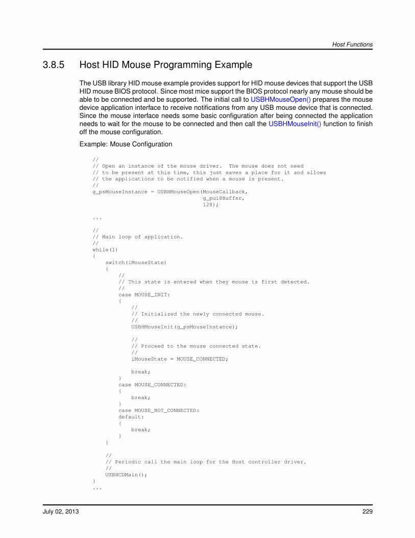
Host Functions
3.8.5 Host HID Mouse Programming Example
The USB library HID mouse example provides support for HID mouse devices that support the USBHID mouse BIOS protocol. Since most mice support the BIOS protocol nearly any mouse should beable to be connected and be supported. The initial call to USBHMouseOpen() prepares the mousedevice application interface to receive notifications from any USB mouse device that is connected.Since the mouse interface needs some basic configuration after being connected the applicationneeds to wait for the mouse to be connected and then call the USBHMouseInit() function to finishoff the mouse configuration.
Example: Mouse Configuration
//// Open an instance of the mouse driver. The mouse does not need// to be present at this time, this just saves a place for it and allows// the applications to be notified when a mouse is present.//g_psMouseInstance = USBHMouseOpen(MouseCallback,
g_pui8Buffer,128);
...
//// Main loop of application.//while(1){
switch(iMouseState){
//// This state is entered when they mouse is first detected.//case MOUSE_INIT:{
//// Initialized the newly connected mouse.//USBHMouseInit(g_psMouseInstance);
//// Proceed to the mouse connected state.//iMouseState = MOUSE_CONNECTED;
break;}case MOUSE_CONNECTED:{
break;}case MOUSE_NOT_CONNECTED:default:{
break;}
}
//// Periodic call the main loop for the Host controller driver.//USBHCDMain();
}...
July 02, 2013 229
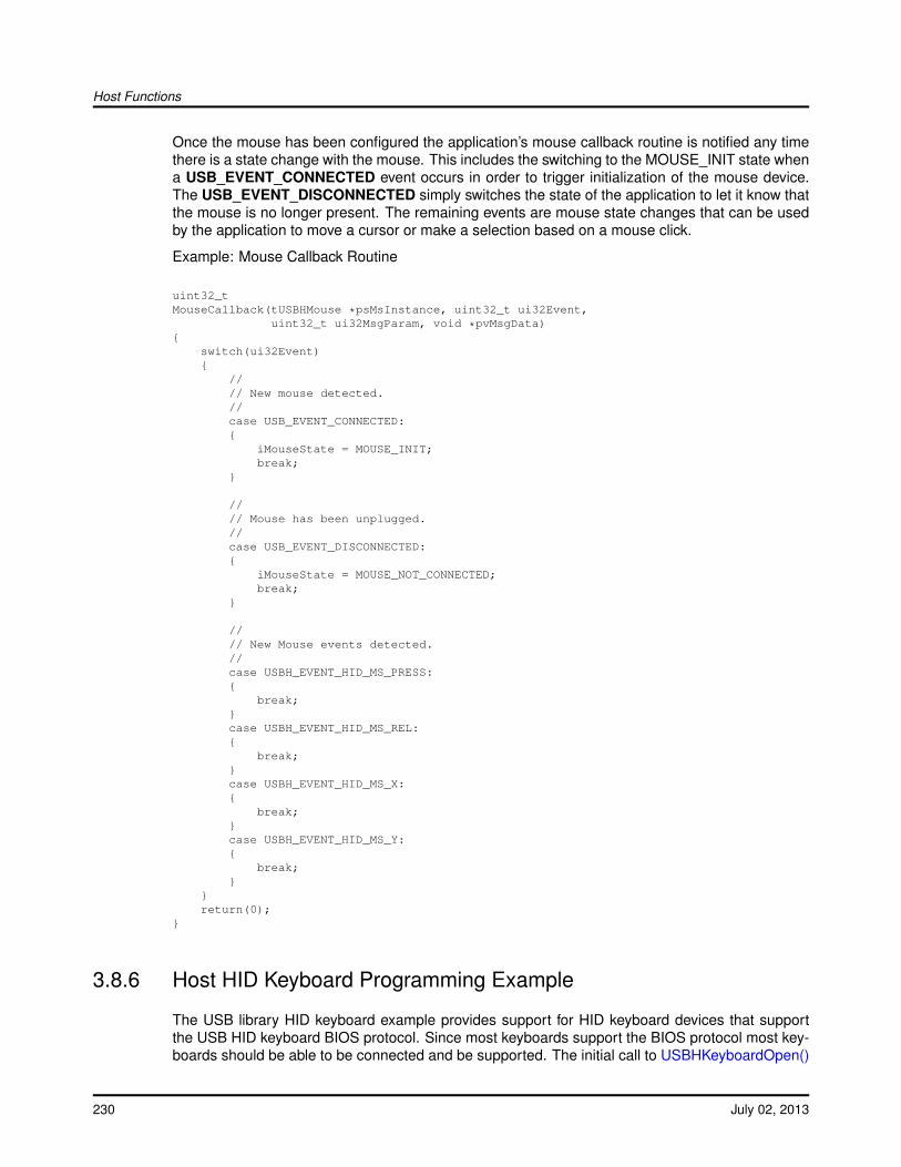
Host Functions
Once the mouse has been configured the application’s mouse callback routine is notified any timethere is a state change with the mouse. This includes the switching to the MOUSE_INIT state whena USB_EVENT_CONNECTED event occurs in order to trigger initialization of the mouse device.The USB_EVENT_DISCONNECTED simply switches the state of the application to let it know thatthe mouse is no longer present. The remaining events are mouse state changes that can be usedby the application to move a cursor or make a selection based on a mouse click.
Example: Mouse Callback Routine
uint32_tMouseCallback(tUSBHMouse *psMsInstance, uint32_t ui32Event,
uint32_t ui32MsgParam, void *pvMsgData){
switch(ui32Event){
//// New mouse detected.//case USB_EVENT_CONNECTED:{
iMouseState = MOUSE_INIT;break;
}
//// Mouse has been unplugged.//case USB_EVENT_DISCONNECTED:{
iMouseState = MOUSE_NOT_CONNECTED;break;
}
//// New Mouse events detected.//case USBH_EVENT_HID_MS_PRESS:{
break;}case USBH_EVENT_HID_MS_REL:{
break;}case USBH_EVENT_HID_MS_X:{
break;}case USBH_EVENT_HID_MS_Y:{
break;}
}return(0);
}
3.8.6 Host HID Keyboard Programming Example
The USB library HID keyboard example provides support for HID keyboard devices that supportthe USB HID keyboard BIOS protocol. Since most keyboards support the BIOS protocol most key-boards should be able to be connected and be supported. The initial call to USBHKeyboardOpen()
230 July 02, 2013
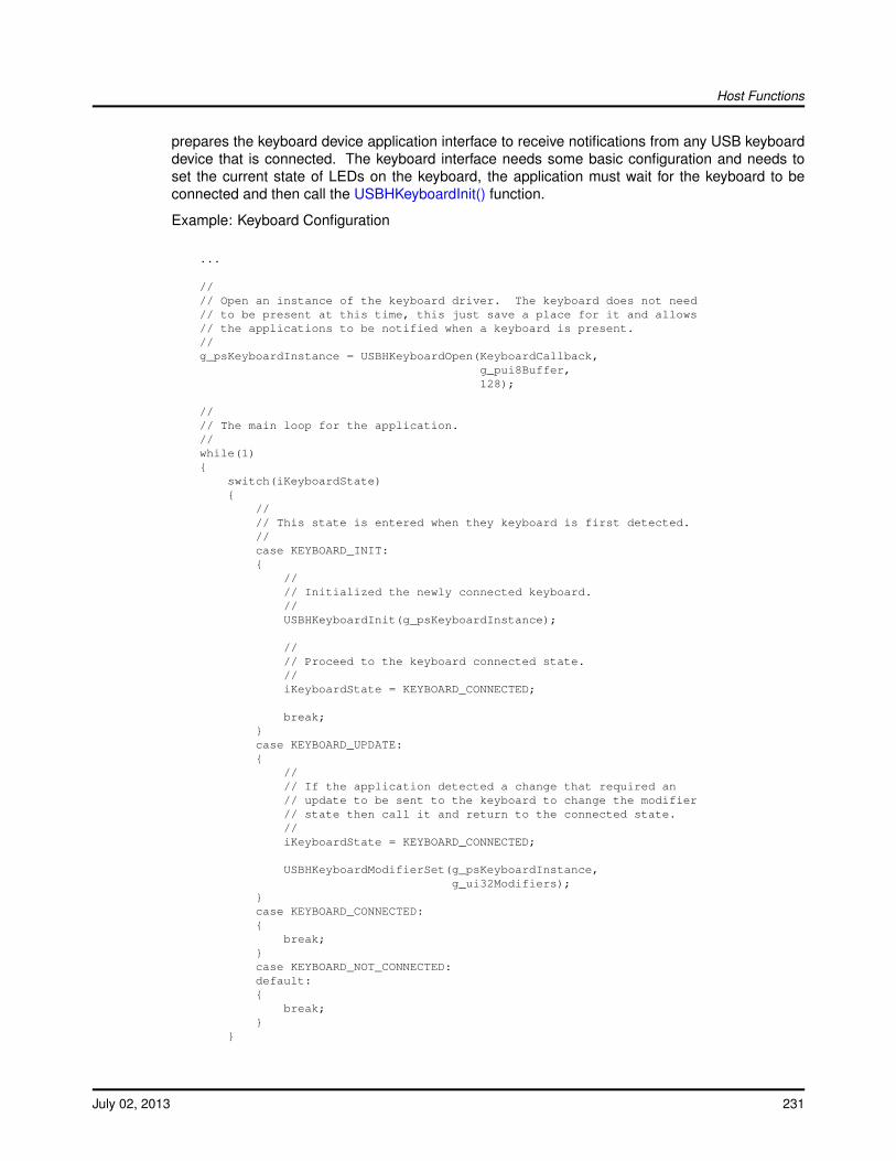
Host Functions
prepares the keyboard device application interface to receive notifications from any USB keyboarddevice that is connected. The keyboard interface needs some basic configuration and needs toset the current state of LEDs on the keyboard, the application must wait for the keyboard to beconnected and then call the USBHKeyboardInit() function.
Example: Keyboard Configuration
...
//// Open an instance of the keyboard driver. The keyboard does not need// to be present at this time, this just save a place for it and allows// the applications to be notified when a keyboard is present.//g_psKeyboardInstance = USBHKeyboardOpen(KeyboardCallback,
g_pui8Buffer,128);
//// The main loop for the application.//while(1){
switch(iKeyboardState){
//// This state is entered when they keyboard is first detected.//case KEYBOARD_INIT:{
//// Initialized the newly connected keyboard.//USBHKeyboardInit(g_psKeyboardInstance);
//// Proceed to the keyboard connected state.//iKeyboardState = KEYBOARD_CONNECTED;
break;}case KEYBOARD_UPDATE:{
//// If the application detected a change that required an// update to be sent to the keyboard to change the modifier// state then call it and return to the connected state.//iKeyboardState = KEYBOARD_CONNECTED;
USBHKeyboardModifierSet(g_psKeyboardInstance,g_ui32Modifiers);
}case KEYBOARD_CONNECTED:{
break;}case KEYBOARD_NOT_CONNECTED:default:{
break;}
}
July 02, 2013 231

Host Functions
//// Periodic call the main loop for the Host controller driver.//USBHCDMain();
}
Much like the mouse, the keyboard handles the reception of events entirely in the callback han-dler. This function should receive and store the keyboard events and handle them in the mainprogram loop when the device is in the connected state. The USB_EVENT_CONNECTED lets themain loop know that it is time to call the USBHKeyboardInit() routine to configure the keyboard.The USB_EVENT_DISCONNECTED event simply informs the application that the keyboard is notlonger present and not to expect any more callbacks until another USB_EVENT_CONNECTED oc-curs. The remaining events all indicate that a key has been pressed or released. Normal keypresses/releases generate USBH_EVENT_HID_KB_PRESS or USBH_EVENT_HID_KB_RELevents while hitting keys like the shift, ctrl, alt and gui keys generate USBH_EVENT_HID_KB_MODevents.
Example: Keyboard Callback
uint32_tKeyboardCallback(tUSBHKeyboard *psKbInstance, uint32_t ui32Event,
uint32_t ui32MsgParam, void *pvMsgData){
uint8_t ui8Char;
switch(ui32Event){
//// New keyboard detected.//case USB_EVENT_CONNECTED:{
iKeyboardState = KEYBOARD_INIT;break;
}
//// Keyboard has been unplugged.//case USB_EVENT_DISCONNECTED:{
iKeyboardState = KEYBOARD_NOT_CONNECTED;break;
}
//// New Key press detected.//case USBH_EVENT_HID_KB_PRESS:{
//// ui32MsgParam holds the USB Usage ID.//break;
}case USBH_EVENT_HID_KB_MOD:{
//// ui32MsgParam holds the USB Modifier bit mask.//break;
}case USBH_EVENT_HID_KB_REL:
232 July 02, 2013
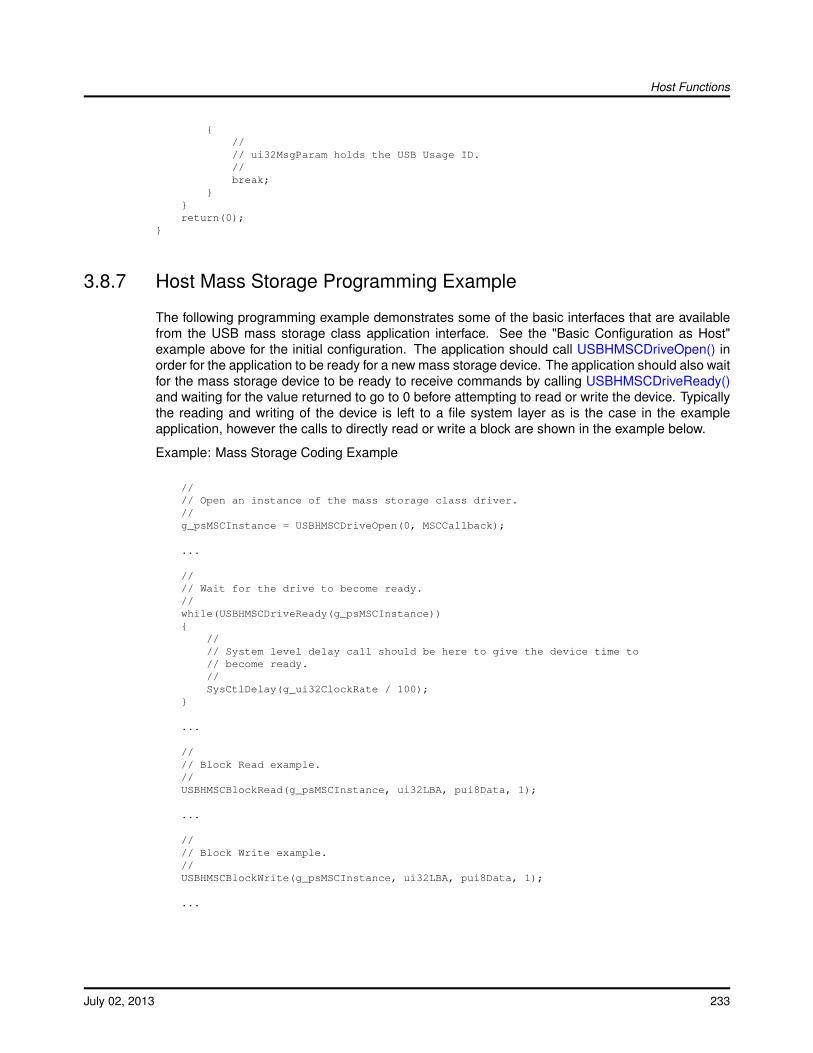
Host Functions
{//// ui32MsgParam holds the USB Usage ID.//break;
}}return(0);
}
3.8.7 Host Mass Storage Programming Example
The following programming example demonstrates some of the basic interfaces that are availablefrom the USB mass storage class application interface. See the "Basic Configuration as Host"example above for the initial configuration. The application should call USBHMSCDriveOpen() inorder for the application to be ready for a new mass storage device. The application should also waitfor the mass storage device to be ready to receive commands by calling USBHMSCDriveReady()and waiting for the value returned to go to 0 before attempting to read or write the device. Typicallythe reading and writing of the device is left to a file system layer as is the case in the exampleapplication, however the calls to directly read or write a block are shown in the example below.
Example: Mass Storage Coding Example
//// Open an instance of the mass storage class driver.//g_psMSCInstance = USBHMSCDriveOpen(0, MSCCallback);
...
//// Wait for the drive to become ready.//while(USBHMSCDriveReady(g_psMSCInstance)){
//// System level delay call should be here to give the device time to// become ready.//SysCtlDelay(g_ui32ClockRate / 100);
}
...
//// Block Read example.//USBHMSCBlockRead(g_psMSCInstance, ui32LBA, pui8Data, 1);
...
//// Block Write example.//USBHMSCBlockWrite(g_psMSCInstance, ui32LBA, pui8Data, 1);
...
July 02, 2013 233

Host Functions
234 July 02, 2013
OTG Functions
4 OTG FunctionsIntroduction . . . . . . . . . . . . . . . . . . . . . . . . . . . . . . . . . . . . . . . . . . . . . . . . . . . . . . . . . . . . . . . . . . . . . . . . . . . . . . . . . . . . . . . . . . . . .235OTG Stack . . . . . . . . . . . . . . . . . . . . . . . . . . . . . . . . . . . . . . . . . . . . . . . . . . . . . . . . . . . . . . . . . . . . . . . . . . . . . . . . . . . . . . . . . . . . . 235OTG Stack Definitions . . . . . . . . . . . . . . . . . . . . . . . . . . . . . . . . . . . . . . . . . . . . . . . . . . . . . . . . . . . . . . . . . . . . . . . . . . . . . . . . . . 237OTG Coding Examples . . . . . . . . . . . . . . . . . . . . . . . . . . . . . . . . . . . . . . . . . . . . . . . . . . . . . . . . . . . . . . . . . . . . . . . . . . . . . . . . . 240
4.1 Introduction
This chapter covers the support provided by the USB library for the USB OTG controller. TheUSB library provides a simplified interface that allows the application to configure how often OTGsessions are requested and a callback method to notify the application when any mode switchhas occurred. Since the OTG portion of the USB library must handle both device and host modeoperation it requires some setup for both device and host modes. This puts some requirements onthe order of initialization of the stacks in order to insure proper operation.
/note The USB library currently only supports OTG session request protocol(SRP) and does notsupport host negotiation protocol(HNP).
Source Code Overview
Source code and headers for the host specific USB functions can be found in the root directory ofthe USB library tree, typically DriverLib/usblib.
usblib.h The header file containing OTG mode and other function prototypes and datatypes offered by the USB library.
usbmode.c The source code for the USB OTG functions are in this file.
4.2 OTG Controller Driver
The USB library OTG functions provide a higher level interface to the USB controller’s OTG hard-ware register interface. The hardware register interface is the lowest level of the interface andit interacts directly with the DriverLib USB APIs. The OTG functions provide the ability to detectwhich end of the USB cable was connected (A side or B side) as well as the presence of a deviceor host being connected. The OTG portion of the USB library requires initialization of the USBlibrary in a certain order to safely bring up the the controller in OTG mode. This is because thestack requires both host and device mode operation. Once the USB library stack is initialized forOTG mode operation, the application will manage OTG notifications via a mode callback functionthat is called any time the USB mode changes.
July 02, 2013 235
OTG Functions
4.2.1 Initialization
The application using the USB library in OTG mode must perform not only the initialization for theOTG functionality but also configure the host and device mode library functions as well. For hostmode this includes registering the supported host classes, configuring the power pins, and callingany application level initialization functions that are required. For device mode, only the applicationlevel initialization is required as the OTG initialization will complete all other initialization requiredby the USB device library.
To properly configure host mode, the application must first configure and enable the host powerpins for USBEPEN and USBPFLT. These are configured using in the library the USBHCDPower-ConfigInit(). The actual physical pins must also be enabled and configured by the application usingSysCtlPeripheralEnable() followed by GPIOPinTypeUSBDigital(). These pins are located on differ-ent physical pins on devices and thus must be configured by the application. The remaining USBpins are handled by the library and do not require any configuration.
Once the pins are configured, the USB library must be put into OTG mode in order to properlyhandle incoming requests. The very first call after pin configuration should be to call USBStack-ModeSet() to register a callback function for OTG events as well as put the library into OTG mode.Next any calls needed to initialize the application level interface for device and host mode need tobe called. For device this would be functions like USBDHIDMouseInit() for a HID mouse or it couldbe USBDCDInit() for a non-library provided device class. For host mode the the drivers must beregistered with a call to USBHCDRegisterDrivers() and if a USB library provided class is used thenit’s application initialization interface must be called as well. For example in the case of supportinga USB mouse, the USBHMouseOpen() should be called to initialize the USB libraries HID mousefunctionality. The last function that should be called by the application to initialize the USB OTGlibrary is to call USBOTGModeInit() in order to finalize the initialization and enable the controller tostart functioning in OTG mode. The USBOTGModeInit() also sets the polling rate for determiningthe mode of the controller as well as provide the memory that is required by the USB library hoststack. Once this call is complete the application should be ready to receive any callbacks from thefunction provided to the USBStackModeSet() and any other device or host specific calls.
4.2.2 Mode Detection
The detection of which end of the cable that the USB controller is on and the current mode isdone automatically in the library. The callback function passed in to USBStackModeSet() providesinformation on mode changes to allow the application to respond. Initially the USB library will startin idle state and remain in that state until a new mode is detected. The rate at which the mode ischecked is passed into the USBOTGModeInit() function or can be set by the USBOTGPollRate()function once the OTG library code has been initialized. If USBOTGPollRate() is called with a pollingrate of zero then polling for mode will stop until the rate is changed to a non-zero value. In a fullOTG system, the polling rate is not required, but it will set how often the USB library issues sessionrequest on B side of the USB cable and how often it will look for devices if on the A side of the cable.Regardless of the mode that is detected the application should periodically call the USBOTGMain()function to allow the polling to function as well as call the USB library’s main function once hostmode is determined. The USBOTGMain() takes the number of elapsed milliseconds since the lastcall to USBOTGMain() in order to provide the USB OTG library functions with some basic timinginformation.
When the USB library detects that it is on the B side of the cable and has been powered, then thelibrary will call back with the mode set to USB_MODE_DEVICE. If the USB controller is connectedto a non-OTG host then the library will simply detect device mode and start operating as a USB
236 July 02, 2013

OTG Functions
device. All other device handling will work exactly as it does for normal device operation. When theUSB cable is disconnected the USB library will return to the idle state and inform the application bycalling the mode callback function with the mode set to USB_MODE_IDLE.
The USB library detects that is is on the A side of the cable via a session request from the B side ordetecting that the A side is connected to a cable due to the polling check. The USB library will thenpower the USB bus, call the mode callback function with the mode set to USB_MODE_HOST, andthen begin enumerating the device. If a non-OTG device was connected the USB library will simplyenumerate the device and function exactly as if the USB controller was in normal host mode.
Once the USB controller is unplugged from the host or detects that a device has been removed inhost mode, the session will end and polling will resume. In both cases the USB library will call thecallback function with the mode set to USB_MODE_NONE to inform the application that the USBlibrary has returned to and idle state and is neither a host or device. Once the USB controller modehas been determined, no other USB library OTG API functions need to be called.
4.2.3 Interrupt Handling
All interrupt handling is done by the USB library USB0OTGModeIntHandler() function which is theinterrupt handler for all USB interrupts in OTG mode. This function must be registered as theinterrupt handler for the USB controller. To simplify handling both modes of operation, the OTGinterrupt handler will take care of routing interrupts to the correct handler in USB library based onthe current mode of operation. The application should be ready to receive any calls from other partsof the USB library based on the current mode of operation that was returned by the mode callbackfunction. Since most callbacks are done in interrupt context they should be treated like interrupthandlers and should defer any real processing of events to occur outside the interrupt context. Thecallbacks are used to notify the applications of events that occur due to OTG negotiations or duringnormal operation.
4.3 OTG Controller Definitions
Functionsvoid USB0OTGModeIntHandler (void)void USBOTGMain (uint32_t ui32MsTicks)void USBOTGModeInit (uint32_t ui32Index, uint32_t ui32PollingRate, void ∗pvPool, uint32_tui32PoolSize)void USBOTGModeTerm (uint32_t ui32Index)void USBOTGPollRate (uint32_t ui32Index, uint32_t ui32PollRate)
4.3.1 Detailed Description
The macros and functions defined in this section can be found in header file usblib.h.
July 02, 2013 237

OTG Functions
4.3.2 Function Documentation
4.3.2.1 USB0OTGModeIntHandler
Handles OTG mode changes and also steers other USB interrupts from the controller to the correcthandler in the USB stack.
Prototype:voidUSB0OTGModeIntHandler(void)
Description:This interrupt handler is used in applications which require to operate in both host and devicemode using OTG. When in host or device mode, it steers the USB hardware interrupt to thecorrect handler in the USB stack depending upon the current operating mode. It also handlesother OTG related interrupt events.
For successful OTG mode operation, an application must register USB0OTGModeIntHandler()in the CPU vector table as the interrupt handler for the USB0 interrupt.
Note:This interrupt handler should only be used on controllers that support OTG functionality.
Returns:None.
4.3.2.2 USBOTGMain
This function is the main routine for the OTG Controller Driver.
Prototype:voidUSBOTGMain(uint32_t ui32MsTicks)
Parameters:ui32MsTicks is the number of milliseconds that have passed since the last time this function
was called.
Description:This function is the main routine for the USB controller when using the library in OTG mode.This routine must be called periodically by the main application outside of a callback context.The ui32MsTicks value is used for basic timing needed by the USB library when operating inOTG mode. This allows for a simple cooperative system to access the the OTG controller driverinterface without the need for an RTOS. All time critical operations are handled in interruptcontext but all longer operations are run from the this function to allow them to block and waitfor completion without holding off other interrupts.
Returns:None.
238 July 02, 2013
OTG Functions
4.3.2.3 USBOTGModeInit
Initializes the USB controller for OTG mode operation.
Prototype:voidUSBOTGModeInit(uint32_t ui32Index,
uint32_t ui32PollingRate,void *pvPool,uint32_t ui32PoolSize)
Parameters:ui32Index specifies the USB controller that is to be initialized for OTG mode operation.ui32PollingRate is the rate in milliseconds to poll the controller for changes in mode.pvPool is a pointer to the data to use as a memory pool for this controller.ui32PoolSize is the size in bytes of the buffer passed in as pvPool .
Description:This function initializes the USB controller hardware into a state suitable for OTG mode oper-ation. Applications must use this function to ensure that the controller is in a neutral state andable to receive appropriate interrupts before host or device mode is chosen by OTG negotia-tion. The ui32PollingRate parameter is used to set the rate at which the USB library will pollthe controller to determine the mode. This has the most effect on how quickly the USB librarywill detect changes when going to host mode. The parameters pvPool and ui32PoolSize arepassed on to the USB host library functions to provide memory for the USB library when it isacting as a host. Any device and host initialization should have been called before calling thisfunction to prevent the USB library from attempting to run in device or host mode before theUSB library is fully configured.
Returns:None.
4.3.2.4 USBOTGModeTerm
Returns the USB controller to and inactive state when in OTG mode operation.
Prototype:voidUSBOTGModeTerm(uint32_t ui32Index)
Parameters:ui32Index specifies the USB controller to end OTG mode operations.
Description:Applications using OTG mode may call this function to disable interrupts in preparation forshutdown or a change of operating mode.
Returns:None.
July 02, 2013 239
OTG Functions
4.3.2.5 USBOTGPollRate
This call sets the USB OTG controllers poll rate when checking for the mode of the controller.
Prototype:voidUSBOTGPollRate(uint32_t ui32Index,
uint32_t ui32PollRate)
Parameters:ui32Index specifies which USB controller to set the polling rate.ui32PollRate is the rate in milliseconds to poll for changes in the controller mode.
Description:This function is called to set the USB OTG libraries polling rate when checking the status of thecable. The ui32PollRate value used sets the rate in milliseconds that the USB OTG library willpoll the cable to see if the controller should enter host mode. This value has no effect on devicedetection rate as the controller will detect being connected to a host controller automatically.The ui32PollRate can be set to 0 to disable polling. The USB OTG library can still function withthe polling rate set to zero, however it will fail to detect host mode properly when no device ispresent at the end of the USB OTG B side of the cable.
Note:This function should only be called on devices that support OTG functionality.
Returns:None.
4.4 OTG Programming Examples
The USB library provides an example OTG application that can act as a mouse device or cansupport being a host to a mouse device. This application uses the USB HID mouse device supportas well as the USB HID mouse host support that is provided with the USB library. To accomplishthis the application must initialize the host stack to support a mouse device and initialize the devicestack to operate as a mouse device. The application should always call USBStackModeSet() inorder to set the mode of the stack to OTG and in order to receive callbacks for any mode changes.
Example: USBStackModeSet
USBStackModeSet(0, USB_MODE_OTG, ModeCallback);
4.4.1 OTG Host Mode Initialization
The USB OTG library requires the application to initialize the host stack almost identically as isdone for normal host mode. The only difference for the USB OTG configuration is that USBHC-DInit() is not called by the application and is handled by the call to USBOTGModeInit(). As withnormal host mode, the application first registers the supported device drivers with a call to USBHC-DRegisterDrivers(). If the top level driver for a device requires any initialization it should be calledas well. Then the application should configure the USB power pins EPEN and FAULT to allow theOTG stack to be able to power the device and detect fault conditions if required. At this point the
240 July 02, 2013
OTG Functions
host mode drivers and stack are ready for normal operation. Unlike normal host mode the applica-tion must periodically call USBOTGMain() instead of USBHCDMain() to allow non-interrupt basedlibrary code to run.
Example: Host Mode Configuration
//// Register the host class drivers.//USBHCDRegisterDrivers(0, g_ppHostClassDrivers, g_ulNumHostClassDrivers);
//// Configure the power pins for host mode.//SysCtlPeripheralEnable(SYSCTL_PERIPH_GPIOH);GPIOPinTypeUSBDigital(GPIO_PORTH_BASE, GPIO_PIN_3 | GPIO_PIN_4);
//// Initialize the power configuration. This sets the power enable signal// to be active high and does not enable the power fault.//USBHCDPowerConfigInit(0, USBHCD_VBUS_AUTO_HIGH);
//// This is the top level call to initialize a mouse driver.//USBHMouseOpen(MouseCallback, g_pucBuffer, MOUSE_MEMORY_SIZE);
4.4.2 OTG Device Mode Initialization
The USB OTG library requires the application to initialize the device stack identically to how it isdone for normal device mode. This includes calling USBDCDInit() for custom classes or a specificUSB library provided device initialization function like USBDHIDMouseInit() in the example below.Once this is done the device mode stack is ready for normal operation in OTG mode.
Example: Device Mode Configuration
//// This is the call to initialize the mouse device stack.//USBDHIDMouseInit(0, (tUSBDHIDMouseDevice *)&g_sMouseDevice);
4.4.3 OTG Mode Initialization
The only remaining initialization required after configuring the device and host stacks is to enableOTG mode with a call to USBOTGModeInit(). This function takes a parameter to specify the pollingintervall for the OTG detection and also two other parameters that are the same as the ones passedto USBHCDInit() as it will pass the memory buffer provided in these two parameters directly toUSBHCDInit(). Once this function returns the OTG stack will be operational and ready for newdevices.
Example: Mouse Configuration
//// Pass in the host stack buffer to the OTG stack.//USBOTGModeInit(0, g_pHCDPool, HCD_MEMORY_SIZE);
July 02, 2013 241
OTG Functions
4.4.4 Application Interface
Once all the host, device and OTG initialization is complete, the USB library is ready to start normaloperation. For device mode this simply means that the next time the device is connected to ahost the application will receive a callback via the function provided with the USBStackModeSet()API. This will inform the application that a device has been detected. Because the USB bus isnot be powered in idle mode, detection of host mode requires polling or actual session requestsignaling from a device in order to detect that host mode should be enabled. In the case wherethe USB controller is connected to the A side of the cable(default Host mode) this will check thecable and inform the application via the mode callback if a device is present. In the case wherethe USB controller is connected to the B side of the cable and an OTG device is on the A side,this call will request that the A side power the USB bus and enumerate the device. If nothing ispresent then the application will receive a callback indicating USB_MODE_NONE as the currentmode was not able to be detected. The application will be informed of a device being disconnectedor being disconnected as a device by receiving a callback that the USB library has returned toUSB_MODE_NONE and possibly also from the USB library device or host library functions aswell.
242 July 02, 2013

General Purpose Functions
5 General Purpose FunctionsIntroduction . . . . . . . . . . . . . . . . . . . . . . . . . . . . . . . . . . . . . . . . . . . . . . . . . . . . . . . . . . . . . . . . . . . . . . . . . . . . . . . . . . . . . . . . . . . . .243Function Definitions . . . . . . . . . . . . . . . . . . . . . . . . . . . . . . . . . . . . . . . . . . . . . . . . . . . . . . . . . . . . . . . . . . . . . . . . . . . . . . . . . . . . .244USB Events . . . . . . . . . . . . . . . . . . . . . . . . . . . . . . . . . . . . . . . . . . . . . . . . . . . . . . . . . . . . . . . . . . . . . . . . . . . . . . . . . . . . . . . . . . . . 253USB Chapter 9 Definitions . . . . . . . . . . . . . . . . . . . . . . . . . . . . . . . . . . . . . . . . . . . . . . . . . . . . . . . . . . . . . . . . . . . . . . . . . . . . . . 259USB Buffer and Ring Buffer APIs . . . . . . . . . . . . . . . . . . . . . . . . . . . . . . . . . . . . . . . . . . . . . . . . . . . . . . . . . . . . . . . . . . . . . . . 267
5.1 Introduction
This chapter describes the set of USB library data types and functions which are of general usein the development of USB applications using this library These elements are not specific to USBhost, device or On-The-Go (OTG) operation.
The functions and types described here fall into three main categories:
Definitions of USB standard types (as found in Chapter 9 of the USB 2.0 specification) andfunctions to parse them.
Functions relating to host/device mode switching for On-The-Go or dual mode applications.
USB device class header files.
Source Code Overview
Source code and headers for the general-purpose USB functions can be found in the top leveldirectory of the USB library tree, typically DriverLib/usblib.
usblib.h The main header file for the USB library containing all data types and def-initions which are common across the library as a whole. Prototypes forgeneral-purpose API functions are also included. All clients of the USB Li-brary should include this header.
usb-ids.h The header file containing labels defining the Texas Instruments USB vendorID (VID) and product IDs (PIDs) for each of the example devices provided inUSB-capable evaluation kits.
usbmsc.h The header file containing definitions specific to the USB Mass StorageClass.
usbcdc.h The header file containing definitions specific to the USB CommunicationDevice Class.
usbhid.h The header file containing definitions specific to the USB Human InterfaceDevice Class.
usbdesc.c The source code for a set of functions allowing parsing of USB descriptors.
usbbuffer.c The source code for a set of functions use to support buffering of USB end-point data streams in some applications.
July 02, 2013 243
General Purpose Functions
usbringbuf.c The source code for a set of functions implementing simple ring buffers.
usbmode.c The source code for a set of functions related to switching between host anddevice modes of operation.
usbtick.c The source code for internal USB library tick handler functions. This file doesnot include any functions accessible by applications.
usblibpriv.h The private header file used to share variables and definitions between thevarious components of the USB Library. Client applications must not includethis header.
5.2 Function Definitions
DefinesUSB_DESC_ANYUSBERR_DEV_RX_DATA_ERRORUSBERR_DEV_RX_FIFO_FULLUSBERR_DEV_RX_OVERRUNUSBERR_HOST_EP0_ERRORUSBERR_HOST_EP0_NAK_TOUSBERR_HOST_IN_DATA_ERRORUSBERR_HOST_IN_ERRORUSBERR_HOST_IN_FIFO_FULLUSBERR_HOST_IN_NAK_TOUSBERR_HOST_IN_NOT_COMPUSBERR_HOST_IN_PID_ERRORUSBERR_HOST_IN_STALLUSBERR_HOST_OUT_ERRORUSBERR_HOST_OUT_NAK_TOUSBERR_HOST_OUT_NOT_COMPUSBERR_HOST_OUT_STALL
EnumerationstUSBMode
FunctionstDescriptorHeader ∗ USBDescGet (tDescriptorHeader ∗psDesc, uint32_t ui32Size, uint32_tui32Type, uint32_t ui32Index)tInterfaceDescriptor ∗ USBDescGetInterface (tConfigDescriptor ∗psConfig, uint32_tui32Index, uint32_t ui32Alt)
244 July 02, 2013
General Purpose Functions
tEndpointDescriptor ∗ USBDescGetInterfaceEndpoint (tInterfaceDescriptor ∗psInterface,uint32_t ui32Index, uint32_t ui32Size)uint32_t USBDescGetNum (tDescriptorHeader ∗psDesc, uint32_t ui32Size, uint32_tui32Type)uint32_t USBDescGetNumAlternateInterfaces (tConfigDescriptor ∗psConfig, uint8_tui8InterfaceNumber)void USBStackModeSet (uint32_t ui32Index, tUSBMode iUSBMode, tUSBModeCallback pfn-Callback)
5.2.1 Detailed Description
This group of functions relates to standard USB descriptor parsing and host/device mode con-trol. Source for these functions can be found in files usbenum.c and usbmode.c. Header fileusblib.h contains prototypes for these functions along with all data type definitions which are notdevice or host specific.
5.2.2 Define Documentation
5.2.2.1 USB_DESC_ANY
Definition:#define USB_DESC_ANY
Description:The USB_DESC_ANY label is used as a wild card in several of the descriptor parsing APIs todetermine whether or not particular search criteria should be ignored.
5.2.2.2 USBERR_DEV_RX_DATA_ERROR
Definition:#define USBERR_DEV_RX_DATA_ERROR
Description:The device detected a CRC error in received data.
5.2.2.3 USBERR_DEV_RX_FIFO_FULL
Definition:#define USBERR_DEV_RX_FIFO_FULL
Description:The device receive FIFO is full.
July 02, 2013 245
General Purpose Functions
5.2.2.4 USBERR_DEV_RX_OVERRUN
Definition:#define USBERR_DEV_RX_OVERRUN
Description:The device was unable to receive a packet from the host since the receive FIFO is full.
5.2.2.5 USBERR_HOST_EP0_ERROR
Definition:#define USBERR_HOST_EP0_ERROR
Description:The host failed to communicate with a device via an endpoint zero.
5.2.2.6 USBERR_HOST_EP0_NAK_TO
Definition:#define USBERR_HOST_EP0_NAK_TO
Description:The host received NAK on endpoint 0 for longer than the configured timeout.
5.2.2.7 USBERR_HOST_IN_DATA_ERROR
Definition:#define USBERR_HOST_IN_DATA_ERROR
Description:The host detected a CRC or bit-stuffing error (isochronous mode).
5.2.2.8 USBERR_HOST_IN_ERROR
Definition:#define USBERR_HOST_IN_ERROR
Description:The host failed to communicate with a device via an IN endpoint.
5.2.2.9 USBERR_HOST_IN_FIFO_FULL
Definition:#define USBERR_HOST_IN_FIFO_FULL
Description:The host receive FIFO is full.
246 July 02, 2013
General Purpose Functions
5.2.2.10 USBERR_HOST_IN_NAK_TO
Definition:#define USBERR_HOST_IN_NAK_TO
Description:The host received NAK on an IN endpoint for longer than the specified timeout period (interrupt,bulk and control modes).
5.2.2.11 USBERR_HOST_IN_NOT_COMP
Definition:#define USBERR_HOST_IN_NOT_COMP
Description:The host did not receive a response from a device.
5.2.2.12 USBERR_HOST_IN_PID_ERROR
Definition:#define USBERR_HOST_IN_PID_ERROR
Description:The host received an invalid PID in a transaction.
5.2.2.13 USBERR_HOST_IN_STALL
Definition:#define USBERR_HOST_IN_STALL
Description:The host received a stall on an IN endpoint.
5.2.2.14 USBERR_HOST_OUT_ERROR
Definition:#define USBERR_HOST_OUT_ERROR
Description:The host failed to communicate with a device via an OUT endpoint.
5.2.2.15 USBERR_HOST_OUT_NAK_TO
Definition:#define USBERR_HOST_OUT_NAK_TO
July 02, 2013 247

General Purpose Functions
Description:The host received NAK on an OUT endpoint for longer than the specified timeout period (bulk,interrupt and control modes).
5.2.2.16 USBERR_HOST_OUT_NOT_COMP
Definition:#define USBERR_HOST_OUT_NOT_COMP
Description:The host did not receive a response from a device (isochronous mode).
5.2.2.17 USBERR_HOST_OUT_STALL
Definition:#define USBERR_HOST_OUT_STALL
Description:The host received a stall on an OUT endpoint.
5.2.3 Typedef Documentation
5.2.3.1 tUSBCallback
USB callback function.
Definition:#define uint32_t(
*tUSBCallback)(void
*pvCBData,uint32_tui32Event,uint32_tui32MsgParam,void
*pvMsgData)
Parameters:pvCBData is the callback pointer associated with the instance generating the callback. This
is a value provided by the client during initialization of the instance making the callback.ui32Event is the identifier of the asynchronous event which is being notified to the client.ui32MsgParam is an event-specific parameter.pvMsgData is an event-specific data pointer.
248 July 02, 2013

General Purpose Functions
Description:A function pointer provided to the USB layer by the application which will be called to notify itof all asynchronous events relating to data transmission or reception. This callback is used bydevice class drivers and host pipe functions.
Returns:Returns an event-dependent value.
5.2.4 Enumeration Documentation
5.2.4.1 tUSBMode
Description:The operating mode required by the USB library client. This type is used by applications whichwish to be able to switch between host and device modes by calling the USBStackModeSet()API.
Enumerators:eUSBModeDevice Operate in USB device mode with active monitoring of VBUS and the ID
pin must be pulled to a logic high value.eUSBModeHost Operate in USB host mode with active monitoring of VBUS and the ID pin
must be pulled to a logic low value.eUSBModeOTG Operate as an On-The-Go device which requires both VBUS and ID to be
connected directly to the USB controller from the USB connector.eUSBModeNone A marker indicating that no USB mode has yet been set by the application.
eUSBModeForceHost Force host mode so that the VBUS and ID pins are not used or mon-itored by the USB controller.
eUSBModeForceDevice Forcing device mode so that the VBUS and ID pins are not used ormonitored by the USB controller.
5.2.5 Function Documentation
5.2.5.1 USBDescGet
Determines the number of individual descriptors of a particular type within a supplied buffer.
Prototype:tDescriptorHeader *USBDescGet(tDescriptorHeader *psDesc,
uint32_t ui32Size,uint32_t ui32Type,uint32_t ui32Index)
Parameters:psDesc points to the first byte of a block of standard USB descriptors.ui32Size is the number of bytes of descriptor data found at pointer psDesc.ui32Type identifies the type of descriptor that is to be found. If the value is USB_DESC_ANY,
the function returns a pointer to the n-th descriptor regardless of type.
July 02, 2013 249
General Purpose Functions
ui32Index is the zero based index of the descriptor whose pointer is to be returned. Forexample, passing value 1 in ui32Index returns the second matching descriptor.
Description:Return a pointer to the n-th descriptor of a particular type found in the block of ui32Size bytesstarting at psDesc.
Returns:Returns a pointer to the header of the required descriptor if found or NULL otherwise.
5.2.5.2 USBDescGetInterface
Returns a pointer to the n-th interface descriptor in a configuration descriptor that applies to thesupplied alternate setting number.
Prototype:tInterfaceDescriptor *USBDescGetInterface(tConfigDescriptor *psConfig,
uint32_t ui32Index,uint32_t ui32Alt)
Parameters:psConfig points to the first byte of a standard USB configuration descriptor.ui32Index is the zero based index of the interface that is to be found. If ui32Alt is set to a
value other than USB_DESC_ANY, this will be equivalent to the interface number beingsearched for.
ui32Alt is the alternate setting number which is to be searched for. If this value isUSB_DESC_ANY, the alternate setting is ignored and all interface descriptors are con-sidered in the search.
Description:Return a pointer to the n-th interface descriptor found in the supplied configuration descriptor.If ui32Alt is not USB_DESC_ANY, only interface descriptors which are part of the supplied al-ternate setting are considered in the search otherwise all interface descriptors are considered.
Note that, although alternate settings can be applied on an interface-by- interface basis, thenumber of interfaces offered is fixed for a given config descriptor. Hence, this function willcorrectly find the unique interface descriptor for that interface’s alternate setting number ui32Altif ui32Index is set to the required interface number and ui32Alt is set to a valid alternate settingnumber for that interface.
Returns:Returns a pointer to the required interface descriptor if found or NULL otherwise.
5.2.5.3 USBDescGetInterfaceEndpoint
Return a pointer to the n-th endpoint descriptor in the supplied interface descriptor.
Prototype:tEndpointDescriptor *USBDescGetInterfaceEndpoint(tInterfaceDescriptor *psInterface,
250 July 02, 2013
General Purpose Functions
uint32_t ui32Index,uint32_t ui32Size)
Parameters:psInterface points to the first byte of a standard USB interface descriptor.ui32Index is the zero based index of the endpoint that is to be found.ui32Size contains the maximum number of bytes that the function may search beyond psIn-
terface while looking for the requested endpoint descriptor.
Description:Return a pointer to the n-th endpoint descriptor found in the supplied interface descriptor. Ifthe ui32Index parameter is invalid (greater than or equal to the bNumEndpoints field of theinterface descriptor) or the endpoint cannot be found within ui32Size bytes of the interfacedescriptor pointer, the function will return NULL.
Note that, although the USB 2.0 specification states that endpoint descriptors must follow theinterface descriptor that they relate to, it also states that device specific descriptors shouldfollow any standard descriptor that they relate to. As a result, we cannot assume that eachinterface descriptor will be followed by nothing but an ordered list of its own endpoints and,hence, the function needs to be provided ui32Size to limit the search range.
Returns:Returns a pointer to the requested endpoint descriptor if found or NULL otherwise.
5.2.5.4 USBDescGetNum
Determines the number of individual descriptors of a particular type within a supplied buffer.
Prototype:uint32_tUSBDescGetNum(tDescriptorHeader *psDesc,
uint32_t ui32Size,uint32_t ui32Type)
Parameters:psDesc points to the first byte of a block of standard USB descriptors.ui32Size is the number of bytes of descriptor data found at pointer psDesc.ui32Type identifies the type of descriptor that is to be counted. If the value is
USB_DESC_ANY, the function returns the total number of descriptors regardless of type.
Description:This function can be used to count the number of descriptors of a particular type within a blockof descriptors. The caller can provide a specific type value which the function matches againstthe second byte of each descriptor or, alternatively, can specify USB_DESC_ANY to have thefunction count all descriptors regardless of their type.
Returns:Returns the number of descriptors found in the supplied block of data.
July 02, 2013 251
General Purpose Functions
5.2.5.5 USBDescGetNumAlternateInterfaces
Determines the number of different alternate configurations for a given interface within a configura-tion descriptor.
Prototype:uint32_tUSBDescGetNumAlternateInterfaces(tConfigDescriptor *psConfig,
uint8_t ui8InterfaceNumber)
Parameters:psConfig points to the first byte of a standard USB configuration descriptor.ui8InterfaceNumber is the interface number for which the number of alternate configurations
is to be counted.
Description:This function can be used to count the number of alternate settings for a specific interfacewithin a configuration.
Returns:Returns the number of alternate versions of the specified interface or 0 if the interface numbersupplied cannot be found in the config descriptor.
5.2.5.6 USBStackModeSet
Allows dual mode application to switch between USB device and host modes and provides amethod to force the controller into the desired mode.
Prototype:voidUSBStackModeSet(uint32_t ui32Index,
tUSBMode iUSBMode,tUSBModeCallback pfnCallback)
Parameters:ui32Index specifies the USB controller whose mode of operation is to be set. This parameter
must be set to 0.iUSBMode indicates the mode that the application wishes to operate in. Valid values are
eUSBModeDevice to operate as a USB device and eUSBModeHost to operate as a USBhost.
pfnCallback is a pointer to a function which the USB library will call each time the mode ischanged to indicate the new operating mode. In cases where iUSBMode is set to eithereUSBModeDevice or eUSBModeHost, the callback will be made immediately to allow theapplication to perform any host or device specific initialization.
Description:This function allows a USB application that can operate in host or device mode to indicateto the USB stack the mode that it wishes to use. The caller is responsible for cleaning up theinterface and removing itself from the bus prior to making this call and reconfiguring afterwards.The pfnCallback function can be a NULL(0) value to indicate that no notification is required.
252 July 02, 2013
General Purpose Functions
For successful dual mode mode operation, an application must registerUSB0DualModeIntHandler() as the interrupt handler for the USB0 interrupt. This han-dler is responsible for steering interrupts to the device or host stack depending uponthe chosen mode. Devices which do not require dual mode capability should reg-ister either USB0DeviceIntHandler() or USB0HostIntHandler() instead. RegisteringUSB0DualModeIntHandler() for a single mode application will result in an application bi-nary larger than required since library functions for both USB operating modes will be includedeven though only one mode is required.
Single mode applications (those offering exclusively USB device or USB host functionality) areonly required to call this function if they need to force the mode of the controller to Host orDevice mode. This is usually in the event that the application needs to reused the USBVBUSand/or USBID pins as GPIOs.
Returns:None.
5.3 USB Events
Data StructurestEventInfo
DefinesUSB_EVENT_COMP_CONFIGUSB_EVENT_COMP_EP_CHANGEUSB_EVENT_COMP_IFACE_CHANGEUSB_EVENT_COMP_STR_CHANGEUSB_EVENT_CONNECTEDUSB_EVENT_DATA_REMAININGUSB_EVENT_DISCONNECTEDUSB_EVENT_ERRORUSB_EVENT_POWER_DISABLEUSB_EVENT_POWER_ENABLEUSB_EVENT_POWER_FAULTUSB_EVENT_REQUEST_BUFFERUSB_EVENT_RESUMEUSB_EVENT_RX_AVAILABLEUSB_EVENT_SCHEDULERUSB_EVENT_SOFUSB_EVENT_STALLUSB_EVENT_SUSPENDUSB_EVENT_TX_COMPLETEUSB_EVENT_UNKNOWN_CONNECTED
July 02, 2013 253

General Purpose Functions
5.3.1 Detailed Description
defined events.
5.3.2 Data Structure Documentation
5.3.2.1 tEventInfo
Definition:typedef struct{
uint32_t ui32Event;uint32_t ui32Instance;
}tEventInfo
Members:ui32Event One of the USB_EVENT_ values.ui32Instance The caller supplied instance value that is passed to event handlers.
Description:This structure is used to return generic event based information to an applica-tion. The following events are currently supported: USB_EVENT_CONNECTED,USB_EVENT_DISCONNECTED, USB_EVENT_POWER_FAULT,USB_EVENT_POWER_FAULT, USB_EVENT_POWER_ENABLE,USB_EVENT_POWER_DISABLE and USB_EVENT_SOF.
5.3.3 Define Documentation
5.3.3.1 USB_EVENT_COMP_CONFIG
Definition:#define USB_EVENT_COMP_CONFIG
Description:This define is used with a device class’s pfnDeviceHandler handler function to indicate that theUSB library has changed the configuration descriptor. This allows the class to make final ad-justments to the configuration descriptor. This event is typically due to the class being includedin a composite device.
The pvInstance is a pointer to an instance of the device being accessed.
The ui32Request is USB_EVENT_COMP_CONFIG.
The pvRequestData is a pointer to the beginning of the configuration descriptor for the deviceinstance.
254 July 02, 2013
General Purpose Functions
5.3.3.2 USB_EVENT_COMP_EP_CHANGE
Definition:#define USB_EVENT_COMP_EP_CHANGE
Description:This define is used with a device class’s pfnDeviceHandler handler function to indicate that theUSB library has changed the endpoint number. This event is typically due to the class beingincluded in a composite device.
The pvInstance is a pointer to an instance of the device being accessed.
The ui32Request is USB_EVENT_COMP_EP_CHANGE.
The pvRequestData is a pointer to a two byte array where the first value is the old endpointnumber and the second is the new endpoint number. The endpoint numbers should be ex-actly as USB specification defines them and bit 7 set indicates an IN endpoint and bit 7 clearindicates an OUT endpoint.
5.3.3.3 USB_EVENT_COMP_IFACE_CHANGE
Definition:#define USB_EVENT_COMP_IFACE_CHANGE
Description:This define is used with a device class’s pfnDeviceHandler handler function to indicate that theUSB library has changed the interface number. This event is typically due to the class beingincluded in a composite device.
The pvInstance is a pointer to an instance of the device being accessed.
The ui32Request is USB_EVENT_COMP_IFACE_CHANGE.
The pvRequestData is a pointer to a two byte array where the first value is the old interfacenumber and the second is the new interface number.
5.3.3.4 USB_EVENT_COMP_STR_CHANGE
Definition:#define USB_EVENT_COMP_STR_CHANGE
Description:This define is used with a device class’s pfnDeviceHandler handler function to indicate that theUSB library has changed the string index number for a string. This event is typically due to theclass being included in a composite device.
The pvInstance is a pointer to an instance of the device being accessed.
The ui32Request is USB_EVENT_COMP_STR_CHANGE.
The pvRequestData is a pointer to a two byte array where the first value is the old string indexand the second is the new string index.
July 02, 2013 255
General Purpose Functions
5.3.3.5 USB_EVENT_CONNECTED
Definition:#define USB_EVENT_CONNECTED
Description:The device is now attached to a USB host and ready to begin sending and receiving data (usedby device classes only).
5.3.3.6 USB_EVENT_DATA_REMAINING
Definition:#define USB_EVENT_DATA_REMAINING
Description:This event is sent by a lower layer to inquire about the amount of unprocessed data buffered inthe layers above. It is used in cases where a low level driver needs to ensure that all precedingdata has been processed prior to performing some action or making some notification. Clientsreceiving this event should return the number of bytes of data that are unprocessed or 0 if nooutstanding data remains.
5.3.3.7 USB_EVENT_DISCONNECTED
Definition:#define USB_EVENT_DISCONNECTED
Description:The device has been disconnected from the USB host (used by device classes only).
Note:In device mode, the USB_EVENT_DISCONNECTED will not be reported if the MCU’sPB1/USB0VBUS pin is connected to a fixed +5 Volts rather than directly to the VBUS pinon the USB connector.
5.3.3.8 USB_EVENT_ERROR
Definition:#define USB_EVENT_ERROR
Description:An error has been reported on the channel or pipe. The ui32MsgValue parameter indicates thesource(s) of the error and is the logical OR combination of "USBERR_" flags defined below.
5.3.3.9 USB_EVENT_POWER_DISABLE
Definition:#define USB_EVENT_POWER_DISABLE
256 July 02, 2013
General Purpose Functions
Description:The controller needs power removed, This is only generated on OTG parts if automatic powercontrol is disabled.
5.3.3.10 USB_EVENT_POWER_ENABLE
Definition:#define USB_EVENT_POWER_ENABLE
Description:The controller has detected a A-Side cable and needs power applied This is only generated onOTG parts if automatic power control is disabled.
5.3.3.11 USB_EVENT_POWER_FAULT
Definition:#define USB_EVENT_POWER_FAULT
Description:The host detected a power fault condition.
5.3.3.12 USB_EVENT_REQUEST_BUFFER
Definition:#define USB_EVENT_REQUEST_BUFFER
Description:This event is sent by a lower layer supporting DMA to request a buffer in which the next receivedpacket may be stored. The ui32MsgValue parameter indicates the maximum size of packet thatcan be received in this channel and pvMsgData points to storage which should be written withthe returned buffer pointer. The return value from the callback should be the size of the bufferallocated (which may be less than the maximum size passed in ui32MsgValue if the clientknows that fewer bytes are expected to be received) or 0 if no buffer is being returned.
5.3.3.13 USB_EVENT_RESUME
Definition:#define USB_EVENT_RESUME
Description:The bus has left suspend state.
5.3.3.14 USB_EVENT_RX_AVAILABLE
Definition:#define USB_EVENT_RX_AVAILABLE
July 02, 2013 257
General Purpose Functions
Description:Data has been received and is in the buffer provided or is ready to be read from the FIFO.
5.3.3.15 USB_EVENT_SCHEDULER
Definition:#define USB_EVENT_SCHEDULER
Description:A scheduler event has occurred.
5.3.3.16 USB_EVENT_SOF
Definition:#define USB_EVENT_SOF
Description:A start of frame event has occurred. This event is disabled by default and must be enabled viaa call from the application to USBHCDEventEnable().
5.3.3.17 USB_EVENT_STALL
Definition:#define USB_EVENT_STALL
Description:A device or host has detected a stall condition.
5.3.3.18 USB_EVENT_SUSPEND
Definition:#define USB_EVENT_SUSPEND
Description:The bus has entered suspend state.
5.3.3.19 USB_EVENT_TX_COMPLETE
Definition:#define USB_EVENT_TX_COMPLETE
Description:Data has been sent and acknowledged. If this event is received via the USB buffer callback,the ui32MsgValue parameter indicates the number of bytes from the transmit buffer that havebeen successfully transmitted and acknowledged.
258 July 02, 2013
General Purpose Functions
5.3.3.20 USB_EVENT_UNKNOWN_CONNECTED
Definition:#define USB_EVENT_UNKNOWN_CONNECTED
Description:An unknown device is now attached to a USB host. This value is only valid for the generic eventhandler and not other device handlers. It is useful for applications that want to know when anunknown device is connected and what the class is of the unknown device.
The ui32Instance is actually the class of the unsupported device that was connected.
5.4 USB Chapter 9 Definitions
Data StructurestConfigDescriptortDescriptorHeadertDeviceDescriptortDeviceQualifierDescriptortEndpointDescriptortInterfaceDescriptortString0DescriptortStringDescriptortUSBRequest
DefinesNEXT_USB_DESCRIPTOR(ptr)USB3Byte(ui32Value)USBLong(ui32Value)USBShort(ui16Value)
5.4.1 Detailed Description
This section describes the various data structures and labels relating to standard USB descriptorsand requests as defined in chapter 9 of the USB 2.0 specification. These definitions can be foundin usblib.h.
For ease of use alongside the USB specification, members of the structures defined here are namedto according to the equivalent field in the USB documentation. Note that this convention departsfrom the naming convention applied to all other Texas Instruments data types.
It is important to be aware that all the structures described in this section are byte packed. Appro-priate typedef modifiers are included in usblib.h to ensure the correct packing for all currently-supported toolchains.
The USB 2.0 specification may be downloaded from the USB Implementers Forum (USB-IF) website at http://www.usb.org/developers/docs/.
July 02, 2013 259
General Purpose Functions
5.4.2 Data Structure Documentation
5.4.2.1 tConfigDescriptor
Definition:typedef struct{
uint8_t bLength;uint8_t bDescriptorType;uint16_t wTotalLength;uint8_t bNumInterfaces;uint8_t bConfigurationValue;uint8_t iConfiguration;uint8_t bmAttributes;uint8_t bMaxPower;
}tConfigDescriptor
Members:bLength The length of this descriptor in bytes. All configuration descriptors are 9 bytes long.bDescriptorType The type of the descriptor. For a configuration descriptor, this will be
USB_DTYPE_CONFIGURATION (2).wTotalLength The total length of data returned for this configuration. This includes the com-
bined length of all descriptors (configuration, interface, endpoint and class- or vendor-specific) returned for this configuration.
bNumInterfaces The number of interface supported by this configuration.bConfigurationValue The value used as an argument to the SetConfiguration standard re-
quest to select this configuration.iConfiguration The index of a string descriptor describing this configuration.bmAttributes Attributes of this configuration.bMaxPower The maximum power consumption of the USB device from the bus in this con-
figuration when the device is fully operational. This is expressed in units of 2mA so, forexample, 100 represents 200mA.
Description:This structure describes the USB configuration descriptor as defined in USB 2.0 specificationsection 9.6.3. This structure also applies to the USB other speed configuration descriptordefined in section 9.6.4.
5.4.2.2 tDescriptorHeader
Definition:typedef struct{
uint8_t bLength;uint8_t bDescriptorType;
}tDescriptorHeader
Members:bLength The length of this descriptor (including this length byte) expressed in bytes.
260 July 02, 2013
General Purpose Functions
bDescriptorType The type identifier of the descriptor whose information follows. For stan-dard descriptors, this field could contain, for example, USB_DTYPE_DEVICE to identify adevice descriptor or USB_DTYPE_ENDPOINT to identify an endpoint descriptor.
Description:This structure describes a generic descriptor header. These fields are to be found at thebeginning of all valid USB descriptors.
5.4.2.3 tDeviceDescriptor
Definition:typedef struct{
uint8_t bLength;uint8_t bDescriptorType;uint16_t bcdUSB;uint8_t bDeviceClass;uint8_t bDeviceSubClass;uint8_t bDeviceProtocol;uint8_t bMaxPacketSize0;uint16_t idVendor;uint16_t idProduct;uint16_t bcdDevice;uint8_t iManufacturer;uint8_t iProduct;uint8_t iSerialNumber;uint8_t bNumConfigurations;
}tDeviceDescriptor
Members:bLength The length of this descriptor in bytes. All device descriptors are 18 bytes long.bDescriptorType The type of the descriptor. For a device descriptor, this will be
USB_DTYPE_DEVICE (1).bcdUSB The USB Specification Release Number in BCD format. For USB 2.0, this will be
0x0200.bDeviceClass The device class code.bDeviceSubClass The device subclass code. This value qualifies the value found in the bDe-
viceClass field.bDeviceProtocol The device protocol code. This value is qualified by the values of bDevice-
Class and bDeviceSubClass.bMaxPacketSize0 The maximum packet size for endpoint zero. Valid values are 8, 16, 32 and
64.idVendor The device Vendor ID (VID) as assigned by the USB-IF.idProduct The device Product ID (PID) as assigned by the manufacturer.bcdDevice The device release number in BCD format.iManufacturer The index of a string descriptor describing the manufacturer.iProduct The index of a string descriptor describing the product.iSerialNumber The index of a string descriptor describing the device’s serial number.
July 02, 2013 261
General Purpose Functions
bNumConfigurations The number of possible configurations offered by the device. This fieldindicates the number of distinct configuration descriptors that the device offers.
Description:This structure describes the USB device descriptor as defined in USB 2.0 specification section9.6.1.
5.4.2.4 tDeviceQualifierDescriptor
Definition:typedef struct{
uint8_t bLength;uint8_t bDescriptorType;uint16_t bcdUSB;uint8_t bDeviceClass;uint8_t bDeviceSubClass;uint8_t bDeviceProtocol;uint8_t bMaxPacketSize0;uint8_t bNumConfigurations;uint8_t bReserved;
}tDeviceQualifierDescriptor
Members:bLength The length of this descriptor in bytes. All device qualifier descriptors are 10 bytes
long.bDescriptorType The type of the descriptor. For a device descriptor, this will be
USB_DTYPE_DEVICE_QUAL (6).bcdUSB The USB Specification Release Number in BCD format. For USB 2.0, this will be
0x0200.bDeviceClass The device class code.bDeviceSubClass The device subclass code. This value qualifies the value found in the bDe-
viceClass field.bDeviceProtocol The device protocol code. This value is qualified by the values of bDevice-
Class and bDeviceSubClass.bMaxPacketSize0 The maximum packet size for endpoint zero when operating at a speed
other than high speed.bNumConfigurations The number of other-speed configurations supported.bReserved Reserved for future use. Must be set to zero.
Description:This structure describes the USB device qualifier descriptor as defined in the USB 2.0 specifi-cation, section 9.6.2.
5.4.2.5 tEndpointDescriptor
Definition:typedef struct{
262 July 02, 2013
General Purpose Functions
uint8_t bLength;uint8_t bDescriptorType;uint8_t bEndpointAddress;uint8_t bmAttributes;uint16_t wMaxPacketSize;uint8_t bInterval;
}tEndpointDescriptor
Members:bLength The length of this descriptor in bytes. All endpoint descriptors are 7 bytes long.bDescriptorType The type of the descriptor. For an endpoint descriptor, this will be
USB_DTYPE_ENDPOINT (5).bEndpointAddress The address of the endpoint. This field contains the endpoint number
ORed with flag USB_EP_DESC_OUT or USB_EP_DESC_IN to indicate the endpoint di-rection.
bmAttributes The endpoint transfer type, USB_EP_ATTR_CONTROL,USB_EP_ATTR_ISOC, USB_EP_ATTR_BULK or USB_EP_ATTR_INT and, ifisochronous, additional flags indicating usage type and synchronization method.
wMaxPacketSize The maximum packet size this endpoint is capable of sending or receivingwhen this configuration is selected. For high speed isochronous or interrupt endpoints, bits11 and 12 are used to pass additional information.
bInterval The polling interval for data transfers expressed in frames or micro frames depend-ing upon the operating speed.
Description:This structure describes the USB endpoint descriptor as defined in USB 2.0 specification sec-tion 9.6.6.
5.4.2.6 tInterfaceDescriptor
Definition:typedef struct{
uint8_t bLength;uint8_t bDescriptorType;uint8_t bInterfaceNumber;uint8_t bAlternateSetting;uint8_t bNumEndpoints;uint8_t bInterfaceClass;uint8_t bInterfaceSubClass;uint8_t bInterfaceProtocol;uint8_t iInterface;
}tInterfaceDescriptor
Members:bLength The length of this descriptor in bytes. All interface descriptors are 9 bytes long.bDescriptorType The type of the descriptor. For an interface descriptor, this will be
USB_DTYPE_INTERFACE (4).
July 02, 2013 263

General Purpose Functions
bInterfaceNumber The number of this interface. This is a zero based index into the array ofconcurrent interfaces supported by this configuration.
bAlternateSetting The value used to select this alternate setting for the interface defined inbInterfaceNumber.
bNumEndpoints The number of endpoints used by this interface (excluding endpoint zero).bInterfaceClass The interface class code as assigned by the USB-IF.bInterfaceSubClass The interface subclass code as assigned by the USB-IF.bInterfaceProtocol The interface protocol code as assigned by the USB-IF.iInterface The index of a string descriptor describing this interface.
Description:This structure describes the USB interface descriptor as defined in USB 2.0 specification sec-tion 9.6.5.
5.4.2.7 tString0Descriptor
Definition:typedef struct{
uint8_t bLength;uint8_t bDescriptorType;uint16_t wLANGID[1];
}tString0Descriptor
Members:bLength The length of this descriptor in bytes. This value will vary depending upon the number
of language codes provided in the descriptor.bDescriptorType The type of the descriptor. For a string descriptor, this will be
USB_DTYPE_STRING (3).wLANGID The language code (LANGID) for the first supported language. Note that this de-
scriptor may support multiple languages, in which case, the number of elements in thewLANGID array will increase and bLength will be updated accordingly.
Description:This structure describes the USB string descriptor for index 0 as defined in USB 2.0 specifi-cation section 9.6.7. Note that the number of language IDs is variable and can be determinedby examining bLength. The number of language IDs present in the descriptor is given by((bLength - 2) / 2).
5.4.2.8 tStringDescriptor
Definition:typedef struct{
uint8_t bLength;uint8_t bDescriptorType;uint8_t bString;
}tStringDescriptor
264 July 02, 2013
General Purpose Functions
Members:bLength The length of this descriptor in bytes. This value will be 2 greater than the number of
bytes comprising the UNICODE string that the descriptor contains.bDescriptorType The type of the descriptor. For a string descriptor, this will be
USB_DTYPE_STRING (3).bString The first byte of the UNICODE string. This string is not NULL terminated. Its length
(in bytes) can be computed by subtracting 2 from the value in the bLength field.
Description:This structure describes the USB string descriptor for all string indexes other than 0 as definedin USB 2.0 specification section 9.6.7.
5.4.2.9 tUSBRequest
Definition:typedef struct{
uint8_t bmRequestType;uint8_t bRequest;uint16_t wValue;uint16_t wIndex;uint16_t wLength;
}tUSBRequest
Members:bmRequestType Determines the type and direction of the request.bRequest Identifies the specific request being made.wValue Word-sized field that varies according to the request.wIndex Word-sized field that varies according to the request; typically used to pass an index
or offset.wLength The number of bytes to transfer if there is a data stage to the request.
Description:The standard USB request header as defined in section 9.3 of the USB 2.0 specification.
5.4.3 Define Documentation
5.4.3.1 NEXT_USB_DESCRIPTOR
Traverse to the next USB descriptor in a block.
Definition:#define NEXT_USB_DESCRIPTOR(ptr)
Parameters:ptr points to the first byte of a descriptor in a block of USB descriptors.
Description:This macro aids in traversing lists of descriptors by returning a pointer to the next descriptor inthe list given a pointer to the current one.
July 02, 2013 265
General Purpose Functions
Returns:Returns a pointer to the next descriptor in the block following ptr .
5.4.3.2 USB3Byte
Write a 24-bit value to a USB descriptor block.
Definition:#define USB3Byte(ui32Value)
Parameters:ui32Value is the 24-bit value that to write to the descriptor.
Description:This helper macro is used in descriptor definitions to write three-byte values. Since the con-figuration descriptor contains all interface and endpoint descriptors in a contiguous block ofmemory, these descriptors are typically defined using an array of bytes rather than as packedstructures.
Returns:Not a function.
5.4.3.3 USBLong
Write a 32-bit value to a USB descriptor block.
Definition:#define USBLong(ui32Value)
Parameters:ui32Value is the 32-bit value that to write to the descriptor.
Description:This helper macro is used in descriptor definitions to write four-byte values. Since the con-figuration descriptor contains all interface and endpoint descriptors in a contiguous block ofmemory, these descriptors are typically defined using an array of bytes rather than as packedstructures.
Returns:Not a function.
5.4.3.4 USBShort
Write a 16-bit value to a USB descriptor block.
Definition:#define USBShort(ui16Value)
Parameters:ui16Value is the 16-bit value to write to the descriptor.
266 July 02, 2013
General Purpose Functions
Description:This helper macro is used in descriptor definitions to write two-byte values. Since the con-figuration descriptor contains all interface and endpoint descriptors in a contiguous block ofmemory, these descriptors are typically defined using an array of bytes rather than as packedstructures.
Returns:Not a function.
5.5 USB Buffer and Ring Buffer APIs
Data StructurestUSBBuffertUSBRingBufObject
DefinesUSB_BUFFER_WORKSPACE_SIZE
Functionsvoid ∗ USBBufferCallbackDataSet (tUSBBuffer ∗psBuffer, void ∗pvCBData)uint32_t USBBufferDataAvailable (const tUSBBuffer ∗psBuffer)void USBBufferDataRemoved (const tUSBBuffer ∗psBuffer, uint32_t ui32Length)void USBBufferDataWritten (const tUSBBuffer ∗psBuffer, uint32_t ui32Length)uint32_t USBBufferEventCallback (void ∗pvCBData, uint32_t ui32Event, uint32_tui32MsgValue, void ∗pvMsgData)void USBBufferFlush (const tUSBBuffer ∗psBuffer)void USBBufferInfoGet (const tUSBBuffer ∗psBuffer, tUSBRingBufObject ∗psRingBuf)const tUSBBuffer ∗ USBBufferInit (const tUSBBuffer ∗psBuffer)uint32_t USBBufferRead (const tUSBBuffer ∗psBuffer, uint8_t ∗pui8Data, uint32_t ui32Length)uint32_t USBBufferSpaceAvailable (const tUSBBuffer ∗psBuffer)uint32_t USBBufferWrite (const tUSBBuffer ∗psBuffer, const uint8_t ∗pui8Data, uint32_tui32Length)void USBBufferZeroLengthPacketInsert (const tUSBBuffer ∗psBuffer, bool bSendZLP)void USBRingBufAdvanceRead (tUSBRingBufObject ∗psUSBRingBuf, uint32_tui32NumBytes)void USBRingBufAdvanceWrite (tUSBRingBufObject ∗psUSBRingBuf, uint32_tui32NumBytes)uint32_t USBRingBufContigFree (tUSBRingBufObject ∗psUSBRingBuf)uint32_t USBRingBufContigUsed (tUSBRingBufObject ∗psUSBRingBuf)bool USBRingBufEmpty (tUSBRingBufObject ∗psUSBRingBuf)void USBRingBufFlush (tUSBRingBufObject ∗psUSBRingBuf)uint32_t USBRingBufFree (tUSBRingBufObject ∗psUSBRingBuf)
July 02, 2013 267

General Purpose Functions
bool USBRingBufFull (tUSBRingBufObject ∗psUSBRingBuf)void USBRingBufInit (tUSBRingBufObject ∗psUSBRingBuf, uint8_t ∗pui8Buf, uint32_tui32Size)void USBRingBufRead (tUSBRingBufObject ∗psUSBRingBuf, uint8_t ∗pui8Data, uint32_tui32Length)uint8_t USBRingBufReadOne (tUSBRingBufObject ∗psUSBRingBuf)uint32_t USBRingBufSize (tUSBRingBufObject ∗psUSBRingBuf)uint32_t USBRingBufUsed (tUSBRingBufObject ∗psUSBRingBuf)void USBRingBufWrite (tUSBRingBufObject ∗psUSBRingBuf, const uint8_t ∗pui8Data,uint32_t ui32Length)void USBRingBufWriteOne (tUSBRingBufObject ∗psUSBRingBuf, uint8_t ui8Data)
5.5.1 Detailed Description
At the lowest level, USB communication is packet-based with the size of each packet dependentupon the configuration of the USB endpoint. In addition, when a packet is in transit, no more datamay be sent on that endpoint until the transmission completes so state machines are required toensure that data is only sent when it is safe to do so.
This model is suitable for some applications but in other cases a simple read/write model allowingarbitrarily sized blocks of data to be received or transmitted at times suitable to the application ismore appropriate. The USB buffer API allows an application to chose this type of operation whenused in conjunction with particular host- or device-class drivers.
A USB buffer provides a unidirectional buffer for a single endpoint and may be configured for op-eration as either a receive buffer (accepting data from the USB controller and passing it to anapplication) or a transmit buffer (accepting data from the application and passing it to the USBcontroller for transmission). In each case, the buffer handles all packetization or depacketization ofdata and allows the application to read or write arbitrarily-sized blocks of data (subject to the spacelimitations in the buffer, of course) at times suitable to it.
Each USB buffer makes use of a ring buffer object to store the buffered data. The ring buffer object isnot USB-specific and does not interact directly with any USB drivers but the API is made availablesince the functionality may be useful to an application in areas outside USB communication, forexample to buffer data from a UART or other peripheral. If attempting to buffer a USB data stream,however, the USB buffer API should be used since it handles the USB driver-side interaction onbehalf of the application. An application must not mix calls to the two APIs for the same object -if using a USB buffer, only APIs of the form USBBufferXxx() should be used to access that bufferand, similarly, if using a plain ring buffer, only USBRingBufXxx() calls must be used.
Source for the USB buffer and ring buffer functions can be found in files usbbuffer.c andusbringbuf.c. Header file usblib.h contains prototypes and data type definitions for thesefunctions.
5.5.2 Using USB Buffers
The USB buffer object is designed to allow insertion between a USB device class driver and the de-vice application or between the USB host controller driver and a host class driver in an application-and class-independent way. Driver data transfer APIs all use a common prototype as do event call-backs so the USB buffer is inserted into the data path using driver function and instance pointers
268 July 02, 2013
General Purpose Functions
provided in static structures during application initialization. This method has the advantage thatthe USB buffer is not directly dependent upon any specific functions in the USB library and, as aresult, using it does not pull extraneous code into the final application image.
During operation, events from the layer below the buffer are inspected in the buffer’s event han-dler. If they are unrecognized or have no effect on the flow of data, they are passed to the higherlayer unaltered. If they relate to data flow, however, the buffer intercepts them and performs thenecessary actions to transmit or receive data before passing appropriate events to the layer above.
To insert a buffer for use on a transmit or receive channel or pipe, a tUSBBuffer structure mustbe initialized as follows.
bTransmitBuffer This field must be set to true if the buffer is passing data from the appli-cation code to the USB controller or false if passing data from the USBcontroller to the application.
pfnCallback This field should point to the event handler callback function in the appli-cation code. Notifications of asynchronous events relating to the bufferwill be made by calls to this function.
pvCBData The callback data pointer written to this field will be passed as the firstparameter on all future calls to the application event handler (set inpfnCallback). Typically an application will set this pointer to some valueallowing it easy access to data associated with the channel, for examplea pointer to an internal instance data structure. The actual content isapplication specific and the USB buffer merely stores the value andpasses it back to the caller when required.
pfnTransfer This field informs the USB buffer of the function to call whenever data isto be transferred between the buffer and the lower layer. This is used totransmit a packet of data if this is a transmit buffer (bTransmitBuffer setto true) or to receive a packet of data if this is a receive buffer (bTrans-mitBuffer set to false). Taking the example of a buffer used to transmitdata to the USB generic bulk device class driver, this would be set topoint to USBDBulkPacketWrite(). A receive buffer used with the samedriver would have this field set to point to USBDBulkPacketRead().
pfnAvailable For a transmit buffer, this function pointer must be set to point to thelower layer function that can be called to determine whether the rele-vant USB endpoint or pipe is ready to accept a new packet for transmis-sion. For a receive buffer, this field points to the function that should becalled to determine the size of buffer required to read a newly-receivedpacket. Using the same example, a transmit buffer above the USBgeneric bulk device class driver would have this field set to point to US-BDBulkTxPacketAvailable() and a receive buffer above the same driverwould set the field to point to USBDBulkRxPacketAvailable().
pvHandle This field must be set to the handle which should be passed as the firstparameter to the functions provided in pfnTransfer and pfnAvailable.This will typically be a pointer to the instance structure for the lowerlayer object in use. In the case of the USB generic bulk device class,this would be the tUSBDBulkDevice pointer originally passed to (andreturned from) USBDBulkInit().
July 02, 2013 269
General Purpose Functions
pcBuffer This field must be initialized to point to the block of RAM that will beused to buffer data on this channel. The buffer will be managed as aring buffer. If the application wishes to access the buffer directly ratherthan via the USBBufferRead() and USBBufferWrite() APIs (thus avoid-ing a copy operation), it is vital to ensure that ring wrap conditions arecorrectly handled in the application code.
ulBufferSize This field provides the size of the buffer pointed to by pcBuffer in bytes.
pvWorkspace The USB buffer requires a block of RAM in which it can store state vari-ables. This field points to application-supplied RAM that can be usedas workspace by the buffer object. This RAM must not be accessedby the application and must remain accessible to the USB buffer foras long as the buffer exists (between calls to USBBufferInit() and USB-BufferTerm()). The label USB_BUFFER_WORKSPACE_SIZE definesthe number of bytes of workspace required.
Once a transmit buffer is initialized, the application can write data to it using function USBBuffer-Write() whenever space is available and the USB buffer driver will handle packet transmission to thelower layer. Similarly USBBufferRead() can be called to read received data from a receive buffer atany time. In both cases, the USB buffer uses the same event protocol that the lower layers use toindicate to the application when more data can be transferred or when data has been sent. Whendata from the USB controller is added to a receive buffer, USB_EVENT_RX_AVAILABLE is passedto the application and when data is removed from a transmit buffer after having been sent to thelower layer, USB_EVENT_TX_COMPLETE is sent.
Applications usb_dev_bulk and usb_dev_serial provide examples of how to use USB buffersin a device application.
5.5.3 Data Structure Documentation
5.5.3.1 tUSBBuffer
Definition:typedef struct{
bool bTransmitBuffer;tUSBCallback pfnCallback;void *pvCBData;tUSBPacketTransfer pfnTransfer;tUSBPacketAvailable pfnAvailable;void *pvHandle;uint8_t *pui8Buffer;uint32_t ui32BufferSize;void *pvWorkspace;
}tUSBBuffer
Members:bTransmitBuffer This field sets the mode of the buffer. If true, the buffer operates as a transmit
buffer and supports calls to USBBufferWrite by the client. If false, the buffer operates as a
270 July 02, 2013
General Purpose Functions
receive buffer and supports calls to USBBufferRead.pfnCallback A pointer to the callback function which will be called to notify the application of
all asynchronous events related to the operation of the buffer.pvCBData A pointer that the buffer will pass back to the client in the first parameter of all
callbacks related to this instance.pfnTransfer The function which should be called to transmit a packet of data in transmit mode
or receive a packet in receive mode.pfnAvailable The function which should be called to determine if the endpoint is ready to
accept a new packet for transmission in transmit mode or to determine the size of thebuffer required to read a packet in receive mode.
pvHandle The handle to pass to the low level function pointers provided in the pfnTransfer andpfnAvailable members. For USB device use, this is the psDevice parameter required bythe relevant device class driver APIs. For USB host use, this is the pipe identifier returnedby USBHCDPipeAlloc.
pui8Buffer A pointer to memory to be used as the ring buffer for this instance.ui32BufferSize The size, in bytes, of the buffer pointed to by pi8Buffer.pvWorkspace A pointer to USB_BUFFER_WORKSPACE_SIZE bytes of RAM that the buffer
object can use for workspace.
Description:The structure used by the application to initialize a buffer object that will provide buffered accessto either a transmit or receive channel.
5.5.3.2 tUSBRingBufObject
Definition:typedef struct{
uint32_t ui32Size;uint32_t ui32WriteIndex;uint32_t ui32ReadIndex;uint8_t *pui8Buf;
}tUSBRingBufObject
Members:ui32Size The ring buffer size.ui32WriteIndex The ring buffer write index.ui32ReadIndex The ring buffer read index.pui8Buf The ring buffer.
Description:The structure used for encapsulating all the items associated with a ring buffer.
5.5.4 Define Documentation
5.5.4.1 USB_BUFFER_WORKSPACE_SIZE
Definition:#define USB_BUFFER_WORKSPACE_SIZE
July 02, 2013 271

General Purpose Functions
Description:The number of bytes of workspace that each USB buffer object requires. This workspacememory is provided to the buffer on USBBufferInit() in the pvWorkspace field of the tUSBBufferstructure.
5.5.5 Typedef Documentation
5.5.5.1 tUSBPacketAvailable
A function pointer type which describes either a class driver transmit or receive packet availablefunction (both have the same prototype) to the USB buffer object.
5.5.5.2 typedef uint32_t(∗ tUSBPacketTransfer)(void ∗pvHandle, uint8_t ∗pi8Data,uint32_t ui32Length, bool bLast)
Definition:#define uint32_t(
*tUSBPacketAvailable)(void
*pvHandle)
Description:A function pointer type which describes either a class driver packet read or packet write function(both have the same prototype) to the USB buffer object.
5.5.6 Function Documentation
5.5.6.1 void∗ USBBufferCallbackDataSet (tUSBBuffer ∗ psBuffer, void ∗ pvCBData)
Sets the callback pointer supplied to clients of this buffer.
Parameters:psBuffer is the pointer to the buffer instance whose callback data is to be changed.pvCBData is the pointer the client wishes to receive on all future callbacks from this buffer.
This function sets the callback pointer which this buffer will supply to clients as the pvCBDataparameter in all future calls to the event callback.
Note:If this function is to be used, the application must ensure that the tUSBBuffer structure usedto describe this buffer is held in RAM rather than flash. The pvCBData value passed is writtendirectly into this structure.
Returns:Returns the previous callback pointer set for the buffer.
272 July 02, 2013
General Purpose Functions
5.5.6.2 USBBufferDataAvailable
Definition:uint32_t USBBufferDataAvailable (const tUSBBuffer *psBuffer )
Description:Returns the number of bytes of data available in the buffer.
Parameters:psBuffer is the pointer to the buffer instance which is to be queried.
This function may be used to determine the number of bytes of data in a buffer. For a receivebuffer, this indicates the number of bytes that the client can read from the buffer using USB-BufferRead(). For a transmit buffer, this indicates the amount of data that remains to be sent tothe USB controller.
Returns:Returns the number of bytes of data in the buffer.
5.5.6.3 USBBufferDataRemoved
Definition:void USBBufferDataRemoved (const tUSBBuffer *psBuffer , uint32_t
ui32Length )
Description:Indicates that a client has read data directly out of the buffer.
Parameters:psBuffer is the pointer to the buffer instance from which data has been read.ui32Length is the number of bytes of data that the client has read.
This function updates the USB buffer read pointer to remove data that the client has read di-rectly rather than via a call to USBBufferRead(). The function is provided to aid a client wishingto minimize data copying. To read directly from the buffer, a client must call USBBufferInfo-Get() to retrieve the current buffer inpsBufVarsdices. With this information, the data followingthe current read index can be read. Once the client has processed much data as it needs,USBBufferDataRemoved() must be called to advance the read pointer past the data that hasbeen read and free up that section of the buffer. The client must take care to correctly handlethe wrap point if accessing the buffer directly.
Returns:None.
5.5.6.4 USBBufferDataWritten
Definition:void USBBufferDataWritten (const tUSBBuffer *psBuffer , uint32_t
ui32Length )
Description:Indicates that a client has written data directly into the buffer and wishes to start transmission.
July 02, 2013 273
General Purpose Functions
Parameters:psBuffer is the pointer to the buffer instance into which data has been written.ui32Length is the number of bytes of data that the client has written.
This function updates the USB buffer write pointer and starts transmission of the data in thebuffer assuming the lower layer is ready to receive a new packet. The function is provided to aida client wishing to write data directly into the USB buffer rather than using the USBBufferWrite()function. This may be necessary to control when the USB buffer starts transmission of a largeblock of data, for example.
A transmit buffer will immediately send a new packet on any call to USBBufferWrite() if the un-derlying layer indicates that a transmission can be started. In some cases this is not desirableand a client may wish to write more data to the buffer in advance of starting transmission tothe lower layer. In such cases, USBBufferInfoGet() may be called to retrieve the current ringbuffer indices and the buffer accessed directly. Once the client has written all data it wishesto send (taking care to handle the ring buffer wrap), it should call this function to indicate thattransmission may begin.
Returns:None.
5.5.6.5 USBBufferEventCallback
Definition:uint32_t USBBufferEventCallback (void *pvCBData , uint32_t ui32Event
, uint32_t ui32MsgValue , void *pvMsgData )
Description:Called by the USB buffer to notify the client of asynchronous events.
Parameters:pvCBData is the client-supplied callback pointer associated with this buffer instance.ui32Event is the identifier of the event being sent. This will be a general event identi-
fier of the form USBD_EVENT_xxxx or a device class-dependent event of the formUSBD_CDC_EVENT_xxx or USBD_HID_EVENT_xxx.
ui32MsgValue is an event-specific parameter value.pvMsgData is an event-specific data pointer.
This function is the USB buffer event handler that applications should register with the USBdevice class driver as the callback for the channel which is to be buffered using this buffer.
Note:This function will never be called by an application. It is the handler that allows the USBbuffer to be inserted above the device class driver or host pipe driver and below the appli-cation to offer buffering support.
Returns:The return value is dependent upon the event being processed.
5.5.6.6 USBBufferFlush
Definition:void USBBufferFlush (const tUSBBuffer *psBuffer )
274 July 02, 2013
General Purpose Functions
Description:Flushes a USB buffer, discarding any data that it contains.
Parameters:psBuffer is the pointer to the buffer instance which is to be flushed.
This function discards all data currently in the supplied buffer without processing (transmittingit via the USB controller or passing it to the client depending upon the buffer mode).
Returns:None.
5.5.6.7 USBBufferInfoGet
Definition:void USBBufferInfoGet (const tUSBBuffer *psBuffer ,
tUSBRingBufObject *psRingBuf )
Description:Returns the current ring buffer indices for this USB buffer.
Parameters:psBuffer is the pointer to the buffer instance whose information is being queried.psRingBuf is a pointer to storage that will be written with the current ring buffer control
structure for this USB buffer.
This function is provided to aid a client wishing to write data directly into the USB buffer ratherthan using the USBBufferWrite() function. This may be necessary to control when the USB-Buffer starts transmission of a large block of data, for example.
A transmit buffer will immediately send a new packet on any call to USBBufferWrite() if the un-derlying layer indicates that a transmission can be started. In some cases this is not desirableand a client may wish to wishes to write more data to the buffer in advance of starting trans-mission to the lower layer. In such cases, this function may be called to retrieve the current ringbuffer indices and the buffer accessed directly. Once the client has written all data it wishes tosend, it should call function USBBufferDataWritten() to indicate that transmission may begin.
Returns:None.
5.5.6.8 USBBufferInit
Definition:const tUSBBuffer *USBBufferInit (const tUSBBuffer *psBuffer )
Description:Initializes a USB buffer object to be used with a given USB controller and device or host classdriver.
Parameters:psBuffer points to a structure containing information on the buffer memory to be used and
the underlying device or host class driver whose data is to be buffered. This structuremust remain accessible for as long as the buffer is in use.
July 02, 2013 275
General Purpose Functions
This function is used to initialize a USB buffer object and insert it into the function and callbackinterfaces between an underlying driver and the application. The caller supplies information onboth the RAM to be used to buffer data, the type of buffer to be created (transmit or receive)and the functions to be called in the lower layer to transfer data to or from the USB controller.
Returns:Returns the original buffer structure pointer if successful or NULL if an error is detected.
5.5.6.9 USBBufferRead
Definition:uint32_t USBBufferRead (const tUSBBuffer *psBuffer , uint8_t
*pui8Data , uint32_t ui32Length )
Description:Reads a block of data from a USB receive buffer into storage supplied by the caller.
Parameters:psBuffer is the pointer to the buffer instance from which data is to be read.pui8Data points to a buffer into which the received data will be written.ui32Length is the size of the buffer pointed to by pui8Data.
This function reads up to ui32Length bytes of data received from the USB host into the suppliedapplication buffer. If the receive buffer contains fewer than ui32Length bytes of data, the datathat is present will be copied and the return code will indicate the actual number of bytes copiedto pui8Data.
Returns:Returns the number of bytes of data read.
5.5.6.10 USBBufferSpaceAvailable
Definition:uint32_t USBBufferSpaceAvailable (const tUSBBuffer *psBuffer )
Description:Returns the number of free bytes in the buffer.
Parameters:psBuffer is the pointer to the buffer instance which is to be queried.
This function returns the number of free bytes in the buffer. For a transmit buffer, this indicatesthe maximum number of bytes that can be passed on a call to USBBufferWrite() and acceptedfor transmission. For a receive buffer, it indicates the number of bytes that can be read fromthe USB controller before the buffer will be full.
Returns:Returns the number of free bytes in the buffer.
276 July 02, 2013
General Purpose Functions
5.5.6.11 USBBufferWrite
Definition:uint32_t USBBufferWrite (const tUSBBuffer *psBuffer , const uint8_t
*pui8Data , uint32_t ui32Length )
Description:Writes a block of data to the transmit buffer and queues it for transmission to the USB controller.
Parameters:psBuffer points to the pointer instance into which data is to be written.pui8Data points to the first byte of data which is to be written.ui32Length is the number of bytes of data to write to the buffer.
This function copies the supplied data into the transmit buffer. The transmit buffer data willbe packetized according to the constraints imposed by the lower layer in use and sent tothe USB controller as soon as possible. Once a packet is transmitted and acknowledged,a USB_EVENT_TX_COMPLETE event will be sent to the application callback indicating thenumber of bytes that have been sent from the buffer.
Attempts to send more data than there is space for in the transmit buffer will result in fewerbytes than expected being written. The value returned by the function indicates the actualnumber of bytes copied to the buffer.
Returns:Returns the number of bytes actually written.
5.5.6.12 USBBufferZeroLengthPacketInsert
Definition:void USBBufferZeroLengthPacketInsert (const tUSBBuffer *psBuffer ,
bool bSendZLP )
Description:Enables or disables zero-length packet insertion.
Parameters:psBuffer is the pointer to the buffer instance whose information is being queried.bSendZLP is true to send zero-length packets or false to prevent them from being sent.
This function allows the use of zero-length packets to be controlled by an application. In caseswhere the USB buffer has sent a full (64 byte) packet and then discovers that the transmitbuffer is empty, the default behavior is to do nothing. Some protocols, however, require that azero- length packet be inserted to signal the end of the data. When using such a protocol, thisfunction should be called with bSendZLP set to true to enable the desired behavior.
Returns:None.
5.5.6.13 USBRingBufAdvanceRead
Definition:void USBRingBufAdvanceRead (tructtUSBRingBufObject tUSBRingBufObject
*psUSBRingBuf , uint32_t ui32NumBytes )
July 02, 2013 277
General Purpose Functions
Description:Removes bytes from the ring buffer by advancing the read index.
Parameters:psUSBRingBuf points to the ring buffer from which bytes are to be removed.ui32NumBytes is the number of bytes to be removed from the buffer.
This function advances the ring buffer read index by a given number of bytes, removing thatnumber of bytes of data from the buffer. If ui32NumBytes is larger than the number of bytescurrently in the buffer, the buffer is emptied.
Returns:None.
5.5.6.14 USBRingBufAdvanceWrite
Definition:void USBRingBufAdvanceWrite (tructtUSBRingBufObject
tUSBRingBufObject *psUSBRingBuf , uint32_t ui32NumBytes )
Description:Adds bytes to the ring buffer by advancing the write index.
Parameters:psUSBRingBuf points to the ring buffer to which bytes have been added.ui32NumBytes is the number of bytes added to the buffer.
This function should be used by clients who wish to add data to the buffer directly rather thanvia calls to USBRingBufWrite() or USBRingBufWriteOne(). It advances the write index by agiven number of bytes.
Note:It is considered an error if the ui32NumBytes parameter is larger than the amount of freespace in the buffer and a debug build of this function will fail (ASSERT) if this conditionis detected. In a release build, the buffer read pointer will be advanced if too much datais written but this will, of course, result in some of the oldest data in the buffer beingdiscarded and also, depending upon how data is being read from the buffer, may result ina race condition which could corrupt the read pointer.
Returns:None.
5.5.6.15 USBRingBufContigFree
Definition:uint32_t USBRingBufContigFree (tructtUSBRingBufObject
tUSBRingBufObject *psUSBRingBuf )
Description:Returns number of contiguous free bytes available in a ring buffer.
Parameters:psUSBRingBuf is the ring buffer object to check.
278 July 02, 2013
General Purpose Functions
This function returns the number of contiguous free bytes ahead of the current write pointer inthe ring buffer.
Returns:Returns the number of contiguous bytes available in the ring buffer.
5.5.6.16 USBRingBufContigUsed
Definition:uint32_t USBRingBufContigUsed (tructtUSBRingBufObject
tUSBRingBufObject *psUSBRingBuf )
Description:Returns number of contiguous bytes of data stored in ring buffer ahead of the current readpointer.
Parameters:psUSBRingBuf is the ring buffer object to check.
This function returns the number of contiguous bytes of data available in the ring buffer aheadof the current read pointer. This represents the largest block of data which does not straddlethe buffer wrap.
Returns:Returns the number of contiguous bytes available.
5.5.6.17 USBRingBufEmpty
Definition:bool USBRingBufEmpty (tructtUSBRingBufObject tUSBRingBufObject
*psUSBRingBuf )
Description:Determines whether a ring buffer is empty or not.
Parameters:psUSBRingBuf is the ring buffer object to empty.
This function is used to determine whether or not a given ring buffer is empty. The structureis specifically to ensure that we do not see warnings from the compiler related to the order ofvolatile accesses being undefined.
Returns:Returns true if the buffer is empty or false otherwise.
5.5.6.18 USBRingBufFlush
Definition:void USBRingBufFlush (tructtUSBRingBufObject tUSBRingBufObject
*psUSBRingBuf )
July 02, 2013 279

General Purpose Functions
Description:Empties the ring buffer.
Parameters:psUSBRingBuf is the ring buffer object to empty.
Discards all data from the ring buffer.
Returns:None.
5.5.6.19 USBRingBufFree
Definition:uint32_t USBRingBufFree (tructtUSBRingBufObject tUSBRingBufObject
*psUSBRingBuf )
Description:Returns number of bytes available in a ring buffer.
Parameters:psUSBRingBuf is the ring buffer object to check.
This function returns the number of bytes available in the ring buffer.
Returns:Returns the number of bytes available in the ring buffer.
5.5.6.20 USBRingBufFull
Definition:bool USBRingBufFull (tructtUSBRingBufObject tUSBRingBufObject
*psUSBRingBuf )
Description:Determines whether a ring buffer is full or not.
Parameters:psUSBRingBuf is the ring buffer object to empty.
This function is used to determine whether or not a given ring buffer is full. The structure isspecifically to ensure that we do not see warnings from the compiler related to the order ofvolatile accesses being undefined.
Returns:Returns true if the buffer is full or false otherwise.
5.5.6.21 USBRingBufInit
Definition:void USBRingBufInit (tructtUSBRingBufObject tUSBRingBufObject
*psUSBRingBuf , uint8_t *pui8Buf , uint32_t ui32Size )
280 July 02, 2013
General Purpose Functions
Description:Initializes a ring buffer object.
Parameters:psUSBRingBuf points to the ring buffer to be initialized.pui8Buf points to the data buffer to be used for the ring buffer.ui32Size is the size of the buffer in bytes.
This function initializes a ring buffer object, preparing it to store data.
Returns:None.
5.5.6.22 USBRingBufRead
Definition:void USBRingBufRead (tructtUSBRingBufObject tUSBRingBufObject
*psUSBRingBuf , uint8_t *pui8Data , uint32_t ui32Length )
Description:Reads data from a ring buffer.
Parameters:psUSBRingBuf points to the ring buffer to be read from.pui8Data points to where the data should be stored.ui32Length is the number of bytes to be read.
This function reads a sequence of bytes from a ring buffer.
Returns:None.
5.5.6.23 USBRingBufReadOne
Definition:uint8_t USBRingBufReadOne (tructtUSBRingBufObject tUSBRingBufObject
*psUSBRingBuf )
Description:Reads a single byte of data from a ring buffer.
Parameters:psUSBRingBuf points to the ring buffer to be written to.
This function reads a single byte of data from a ring buffer.
Returns:The byte read from the ring buffer.
July 02, 2013 281
General Purpose Functions
5.5.6.24 USBRingBufSize
Definition:uint32_t USBRingBufSize (tructtUSBRingBufObject tUSBRingBufObject
*psUSBRingBuf )
Description:Returns the size in bytes of a ring buffer.
Parameters:psUSBRingBuf is the ring buffer object to check.
This function returns the size of the ring buffer.
Returns:Returns the size in bytes of the ring buffer.
5.5.6.25 USBRingBufUsed
Definition:uint32_t USBRingBufUsed (tructtUSBRingBufObject tUSBRingBufObject
*psUSBRingBuf )
Description:Returns number of bytes stored in ring buffer.
Parameters:psUSBRingBuf is the ring buffer object to check.
This function returns the number of bytes stored in the ring buffer.
Returns:Returns the number of bytes stored in the ring buffer.
5.5.6.26 USBRingBufWrite
Definition:void USBRingBufWrite (tructtUSBRingBufObject tUSBRingBufObject
*psUSBRingBuf , const uint8_t *pui8Data , uint32_t ui32Length )
Description:Writes data to a ring buffer.
Parameters:psUSBRingBuf points to the ring buffer to be written to.pui8Data points to the data to be written.ui32Length is the number of bytes to be written.
This function write a sequence of bytes into a ring buffer.
Returns:None.
282 July 02, 2013
General Purpose Functions
5.5.6.27 USBRingBufWriteOne
Definition:void USBRingBufWriteOne (tructtUSBRingBufObject tUSBRingBufObject
*psUSBRingBuf , uint8_t ui8Data )
Description:Writes a single byte of data to a ring buffer.
Parameters:psUSBRingBuf points to the ring buffer to be written to.ui8Data is the byte to be written.
This function writes a single byte of data into a ring buffer.
Returns:None.
5.6 Internal USB DMA functions
DefinesUSBLibDMAArbSizeSet(psUSBDMAInst, ui32Channel, ui32ArbSize)USBLibDMAChannelAllocate(psUSBDMAInst, ui8Endpoint, ui32MaxPacketSize, ui32Config)USBLibDMAChannelDisable(psUSBDMAInst, ui32Channel)USBLibDMAChannelEnable(psUSBDMAInst, ui32Channel)USBLibDMAChannelIntDisable(psUSBDMAInst, ui32Channel)USBLibDMAChannelIntEnable(psUSBDMAInst, ui32Channel)USBLibDMAChannelRelease(psUSBDMAInst, ui8Endpoint)USBLibDMAChannelStatus(psUSBDMAInst, ui32Channel)USBLibDMAIntHandler(psUSBDMAInst, ui32Status)USBLibDMAIntStatus(psUSBDMAInst)USBLibDMAIntStatusClear(psUSBDMAInst, ui32Status)USBLibDMAStatus(psUSBDMAInst)USBLibDMATransfer(psUSBDMAInst, ui32Channel, pvBuffer, ui32Size)USBLibDMAUnitSizeSet(psUSBDMAInst, ui32Channel, ui32BitSize)
FunctionstUSBDMAInstance ∗ USBLibDMAInit (uint32_t ui32Index)
5.6.1 Define Documentation
5.6.1.1 USBLibDMAArbSizeSet
This function is used to set the arbitration size for a DMA channel.
July 02, 2013 283
General Purpose Functions
Definition:#define USBLibDMAArbSizeSet(psUSBDMAInst,
ui32Channel,ui32ArbSize)
Parameters:psUSBDMAInst is the DMA instance data for a USB controller.ui32Channel is the DMA channel number to modify.ui32ArbSize is the transfer arbitration size in bytes.
Description:This function configures the individual transfer size of the DMA channel provided in theui32Channel parameter. The ui32Channel must already be allocated to an endpoint by callingthe USBLibDMAChannelAllocate() function.
Returns:None.
5.6.1.2 USBLibDMAChannelAllocate
This function is used to assign a DMA channel to an endpoint.
Definition:#define USBLibDMAChannelAllocate(psUSBDMAInst,
ui8Endpoint,ui32MaxPacketSize,ui32Config)
Parameters:psUSBDMAInst is the DMA instance data for a USB controller.ui8Endpoint is the endpoint number to assign a DMA channel.ui32MaxPacketSize is the maximum packet size for the endpoint assigned that is being as-
signed to the DMA channel.ui32Config are the basic configuration options for the DMA channel.
Description:This function assigns a DMA channel to a given endpoint. The ui8Endpoint parameter is thezero based endpoint number that is assigned a DMA channel. The ui32Config parameter con-tains any configuration options for the DMA channel. The current options include the following:
USB_DMA_EP_TX - this request is for a transmit DMA channel.USB_DMA_EP_RX - this request is for a receive DMA channel.
Note:The maximum number of available DMA channels to endpoints varies between devices.
Returns:Zero or the DMA channel assigned to the endpoint.
284 July 02, 2013
General Purpose Functions
5.6.1.3 USBLibDMAChannelDisable
This function disables DMA for a given DMA channel.
Definition:#define USBLibDMAChannelDisable(psUSBDMAInst,
ui32Channel)
Parameters:psUSBDMAInst is the DMA structure pointer for this instance.ui32Channel is the DMA channel to disable.
Description:This function disables DMA on the channel number passed in the ui32Channel parameter.
Returns:None.
5.6.1.4 USBLibDMAChannelEnable
This function enables DMA for a given channel.
Definition:#define USBLibDMAChannelEnable(psUSBDMAInst,
ui32Channel)
Parameters:psUSBDMAInst is the DMA structure pointer for this instance.ui32Channel is the DMA channel to enable.
Description:This function enables DMA on the channel number passed in the ui32Channel parameter.
Returns:None.
5.6.1.5 USBLibDMAChannelIntDisable
This function disables DMA interrupt for a given DMA channel.
Definition:#define USBLibDMAChannelIntDisable(psUSBDMAInst,
ui32Channel)
Parameters:psUSBDMAInst is the DMA structure pointer for this instance.ui32Channel is the DMA channel interrupt to disable.
Description:This function disables the DMA interrupt on the channel number passed in the ui32Channelparameter.
July 02, 2013 285
General Purpose Functions
Returns:None.
5.6.1.6 USBLibDMAChannelIntEnable
This function enables the DMA interrupt for a given channel.
Definition:#define USBLibDMAChannelIntEnable(psUSBDMAInst,
ui32Channel)
Parameters:psUSBDMAInst is the DMA structure pointer for this instance.ui32Channel is the DMA channel interrupt to enable.
Description:This function enables DMA interrupt on the channel number passed in the ui32Channel pa-rameter.
Returns:None.
5.6.1.7 USBLibDMAChannelRelease
This function is used to free a DMA channel that was assigned to an endpoint.
Definition:#define USBLibDMAChannelRelease(psUSBDMAInst,
ui8Endpoint)
Parameters:psUSBDMAInst is the DMA instance data for a USB controller.ui8Endpoint is the DMA channel number to free up.
Description:This function frees up a DMA channel that was allocated to an endpoint by the USBLibD-MAChannelAllocate() function.
Returns:None.
5.6.1.8 USBLibDMAChannelStatus
This function returns the current DMA status for a given DMA channel.
Definition:#define USBLibDMAChannelStatus(psUSBDMAInst,
ui32Channel)
286 July 02, 2013
General Purpose Functions
Parameters:psUSBDMAInst is the DMA structure pointer for this instance.ui32Channel is the DMA channel number used to retrieve the DMA status.
Description:This function returns the current status of a DMA transfer on a given DMA channel. The DMAchannel is specified by the ui32Channel parameter.
Returns:This function returns one of the USBLIBSTATUS_DMA_∗ values.
5.6.1.9 USBLibDMAIntHandler
This function is called by the USB interrupt handler.
Definition:#define USBLibDMAIntHandler(psUSBDMAInst,
ui32Status)
Parameters:psUSBDMAInst is the DMA structure pointer for this instance.ui32Status is the DMA interrupt status.
Description:This function is called by the USB interrupt handler to allow the DMA interface to handle inter-rupts outside of the context of the normal USB interrupt handler. The ui32Status is the currentDMA interrupt status at the time of the USB interrupt. Since some DMA controller interrupts arecleared automatically when read, this value must be retrieved by calling the USBLibDMAIntSta-tus() function and passed into this function.
Returns:None.
5.6.1.10 USBLibDMAIntStatus
This function returns the current DMA interrupt status.
Definition:#define USBLibDMAIntStatus(psUSBDMAInst)
Parameters:psUSBDMAInst is the DMA structure pointer for this instance.
Description:This function returns the interrupt status for all DMA channels. The value returned is a perchannel interrupt mapping with the DMA channels mapped into bits 0-31 by channel numberwith channel 1 starting at bit 0.
Note:This function does not return an endpoint interrupt status, but the interrupt status for the DMAinterface used with the USB controller.
July 02, 2013 287

General Purpose Functions
Returns:This function returns the pending DMA interrupts.
5.6.1.11 USBLibDMAIntStatusClear
This function clears the requested DMA interrupt status.
Definition:#define USBLibDMAIntStatusClear(psUSBDMAInst,
ui32Status)
Parameters:psUSBDMAInst is the DMA structure pointer for this instance.ui32Status contains the interrupts to clear.
Description:This function clears the current DMA interrupt status for the controller specified by theui32Instance parameter. The ui32Status value has the same format as the value returnedfrom the USBLibDMAIntStatus() function which is a per channel interrupt mapping. The DMAchannels are mapped into bits 0-31 by channel number with channel 1 starting at bit 0.
Returns:None.
5.6.1.12 USBLibDMAStatus
This function is used to return any global status information for USB DMA.
Definition:#define USBLibDMAStatus(psUSBDMAInst)
Parameters:psUSBDMAInst is a generic instance pointer that can be used to distinguish between different
hardware instances.
Description:This function performs returns the global status for the USB DMA interface.
Returns:Always returns 0.
5.6.1.13 USBLibDMATransfer
This function is configures a USB transfer on a given DMA channel.
Definition:#define USBLibDMATransfer(psUSBDMAInst,
ui32Channel,pvBuffer,ui32Size)
288 July 02, 2013

General Purpose Functions
Parameters:psUSBDMAInst is the DMA structure pointer for this instance.ui32Channel is the DMA channel to use.pvBuffer is a pointer to the buffer to use for the transfer.ui32Size is the size of the data to be transferred in bytes.
Description:This function is called to configure a transfer using the USB controller depending on the pa-rameters. The ui32Channel parameter holds the channel number to use for this transfer whichmust have already been allocated with a call to the USBLibDMAChannelAllocate() function.The transaction is configured to transfer ui32Size bytes to/from the buffer held in the pvBufferpointer.
Returns:This function returns the number of bytes scheduled to be transferred.
5.6.1.14 USBLibDMAUnitSizeSet
This function is used to set the individual transfer size of a DMA channel.
Definition:#define USBLibDMAUnitSizeSet(psUSBDMAInst,
ui32Channel,ui32BitSize)
Parameters:psUSBDMAInst is the DMA instance data for a USB controller.ui32Channel is the DMA channel number to modify.ui32BitSize is the individual transfer size in bits(8, 16 or 32).
Description:This function configures the individual transfer size of the DMA channel provided in theui32Channel parameter. The ui32Channel must already be allocated to an endpoint by callingthe USBLibDMAChannelAllocate() function. The ui32BitSize parameter should be on of thefollowing values: 8, 16 or 32.
Returns:None.
5.6.2 Function Documentation
5.6.2.1 USBLibDMAInit
This function is used to initialize the DMA interface for a USB instance.
Prototype:tUSBDMAInstance *USBLibDMAInit(uint32_t ui32Index)
Parameters:ui32Index is the index of the USB controller for this instance.
July 02, 2013 289

General Purpose Functions
Description:This function performs any initialization and configuration of the DMA portions of the USBcontroller. This function returns a pointer that is used with the remaining USBLibDMA APIsor the function returns zero if the requested controller cannot support DMA. If this function iscalled when already initialized it will not reinitialize the DMA controller and will instead returnthe previously initialized DMA instance.
Returns:A pointer to use with USBLibDMA APIs.
290 July 02, 2013

July 02, 2013 291

IMPORTANT NOTICETexas Instruments Incorporated and its subsidiaries (TI) reserve the right to make corrections, enhancements, improvements and otherchanges to its semiconductor products and services per JESD46, latest issue, and to discontinue any product or service per JESD48,latest issue. Buyers should obtain the latest relevant information before placing orders and should verify that such information is currentand complete. All semiconductor products (also referred to herein as “components”) are sold subject to TI’s terms and conditions of salesupplied at the time of order acknowledgment.
TI warrants performance of its components to the specifications applicable at the time of sale, in accordance with the warranty in TI’s termsand conditions of sale of semiconductor products. Testing and other quality control techniques are used to the extent TI deems necessary tosupport this warranty. Except where mandated by applicable law, testing of all parameters of each component is not necessarily performed.
TI assumes no liability for applications assistance or the design of Buyers’ products. Buyers are responsible for their products and appli-cations using TI components. To minimize the risks associated with Buyers’ products and applications, Buyers should provide adequatedesign and operating safeguards.
TI does not warrant or represent that any license, either express or implied, is granted under any patent right, copyright, mask work right, orother intellectual property right relating to any combination, machine, or process in which TI components or services are used. Informationpublished by TI regarding third-party products or services does not constitute a license to use such products or services or a warranty orendorsement thereof. Use of such information may require a license from a third party under the patents or other intellectual property ofthe third party, or a license from TI under the patents or other intellectual property of TI.
Reproduction of significant portions of TI information in TI data books or data sheets is permissible only if reproduction is without alterationand is accompanied by all associated warranties, conditions, limitations, and notices. TI is not responsible or liable for such altereddocumentation. Information of third parties may be subject to additional restrictions.
Resale of TI components or services with statements different from or beyond the parameters stated by TI for that component or servicevoids all express and any implied warranties for the associated TI component or service and is an unfair and deceptive business practice.TI is not responsible or liable for any such statements.
Buyer acknowledges and agrees that it is solely responsible for compliance with all legal, regulatory and safety-related requirementsconcerning its products, and any use of TI components in its applications, notwithstanding any applications-related information or supportthat may be provided by TI. Buyer represents and agrees that it has all the necessary expertise to create and implement safeguards whichanticipate dangerous consequences of failures, monitor failures and their consequences, lessen the likelihood of failures that might causeharm and take appropriate remedial actions. Buyer will fully indemnify TI and its representatives against any damages arising out of theuse of any TI components in safety-critical applications.
In some cases, TI components may be promoted specifically to facilitate safety-related applications. With such components, TI’s goalis to help enable customers to design and create their own end-product solutions that meet applicable functional safety standards andrequirements. Nonetheless, such components are subject to these terms.
No TI components are authorized for use in FDA Class III (or similar life-critical medical equipment) unless authorized officers of the partieshave executed a special agreement specifically governing such use.
Only those TI components which TI has specifically designated as military grade or “enhanced plastic” are designed and intended for usein military/aerospace applications or environments. Buyer acknowledges and agrees that any military or aerospace use of TI componentswhich have not been so designated is solely at the Buyer’s risk, and that Buyer is solely responsible for compliance with all legal andregulatory requirements in connection with such use.
TI has specifically designated certain components as meeting ISO/TS16949 requirements, mainly for automotive use. In any case of useof non-designated products, TI will not be responsible for any failure to meet ISO/TS16949.
Products ApplicationsAudio www.ti.com/audio Automotive and Transportation www.ti.com/automotiveAmplifiers amplifier.ti.com Communications and Telecom www.ti.com/communicationsData Converters dataconverter.ti.com Computers and Peripherals www.ti.com/computersDLP® Products www.dlp.com Consumer Electronics www.ti.com/consumer-appsDSP dsp.ti.com Energy and Lighting www.ti.com/energyClocks and Timers www.ti.com/clocks Industrial www.ti.com/industrialInterface interface.ti.com Medical www.ti.com/medicalLogic logic.ti.com Security www.ti.com/securityPower Mgmt power.ti.com Space, Avionics and Defense www.ti.com/space-avionics-defenseMicrocontrollers microcontroller.ti.com Video and Imaging www.ti.com/videoRFID www.ti-rfid.comOMAP Applications Processors www.ti.com/omap TI E2E Community e2e.ti.comWireless Connectivity www.ti.com/wirelessconnectivity
Mailing Address: Texas Instruments, Post Office Box 655303, Dallas, Texas 75265Copyright © 2008-2013, Texas Instruments Incorporated
292 July 02, 2013