title: evaluation of the effect of water vapor … · ti lere is evidence that surface oh groups...
TRANSCRIPT

TITLE: EVALUATION OF THE EFFECT OF WATER VAPOR ON
THE PERFORMANCE OF NASA'S NMRO CATALYSTS
FOR CARBON MONOXIDE OXIDATION
GRANT NUMBER: NAG-I-2223
PRINCIPAL INVESTIGATORS: Ares Akyurtlu
Jale F. Akyurtlu
INSTITUTION: Hampton University
Department of Chemical Engineering
Hampton, Virginia 23668
SUPPORTED BY: NASA Langley Research Center
Office of Education
Hampton, VA 23665
TECHNICAL MONITOR: David Schryer, Jeff Jordan
STUDENT RESEARCHERS: Vaughnery Ammons, Taikelia Battle, Amy Gay, Kyle Bray, Boe
Washington
FINAL REPORT
Summary of Research
August 1, 1999 - March 31, 2002
https://ntrs.nasa.gov/search.jsp?R=20020061271 2018-09-27T17:18:19+00:00Z

TABLE OF CONTENTS
INTRODUCTION ................................................................................................................. 1
Background Inforcnation .......................................................................... 1
EXPERIMENTAL .................................................................................................................... 2
RESULTS ............................................................................................................................. 3
Effect of Water or the Reduction-Oxidation Properties of the 15%Pt/SnO2 Catalyst .... 3
TPR of Other Catalysts Prepared by NASA/LaRC ............................................ 5
TPD of Other Catalysts Prepared by NASA/LaRC ............................................. 5
Temperature Programmed Reaction Studies with GC-MS Analyzer ......................... 6
CONCLUSIONS ....................................................................................................................... 7
FIGURES ....................................................................................................................................... 9
REFERENCES ............................................................................................... 50
±

INTRODUCTION
The Noble Metal Reducible Oxide (NMRO) catalysts for the low temperature oxidation of carbon
monoxide were developed by NASA for the reoxidation of carbon monoxide which forms by the
dissociation of carbon dioxide during the operation of sealed carbon dioxide lasers. The NMRO
catalyst, which consi:;ts of a noble metal in conjunction with a reducible metal oxide, was evaluated
under conditions that will be encountered in a CO2 laser operation, namely temperatures in the range
298 to 373 K and no 6gnificant reaction gas components other than CO, C02, and 02. The NMRO
catalysts may have significant potential for spin-off applications such as the prevention of carbon
monoxide build-up iv closed spaces as in space vehicle cabins or submarines, and the elimination of
the cold start-up problem of automobile exhaust catalysts. The most significant difference in the
conditions of these possible future applications is the high moisture content of the gases to be
processed. Lack of understanding of the effects of water vapor and high temperature on catalyst
activity and operatiol_ for extended periods are currently the main stumbling blocks for the transfer
of this NASA technology to be used for commercial purposes.
In the original propo _al the following objectives were stated: To obtain experimental data on the
adsorption, desorptio n and reaction characteristics of CO and 02 on the catalysts under high moisture
conditions; to collect evidence on the presence of carbonate and hydroxyl surface species and their
involvement in the CO oxidation mechanism; and to model the reaction system using a Monte-Carlo
simulation to gain insight on the various steps involved. After the work has commenced the NASA
technical monitor Mr David Schryer informed us that there was increased interest in the possible use
of the NMRO catal3sts as automobile exhaust catalysts and therefore NASA wanted to know
whether the catalysts can operate at high temperatures as well as with high moisture gases. At that
meeting it was decided that investigation of the high temperature performance of the NMRO
catalysts should be gi yen priority and replace the Monte-Carlo simulation objective. As a result, the
modified objectives of the investigation were taken as the investigation of the high-temperature
activity of the NMRC. catalysts, and the effect of water vapor on the performance of these catalysts.
Background Information
The noble metal recucible oxide (NMRO) catalysts have very important applications mostly
involving oxidation or reduction reactions where transfer of oxygen atoms takes place. These
catalysts exhibit a strong synergy between the two metal components producing significantly higher
catalytic activities compared to the single metal catalysts. This synergy may arise from three
different types of interactions w. The presence of one component may alter the properties of the other,
the two components nay independently catalyze different catalytic reaction steps, and/or the two
components may combine to form a different surface species that may create new catalytic sites.
The NMRO catalyst,'; that are of interest for low temperature CO oxidation are based on either
platinum or gold as noble metal. Platinum is generally associated with SnO2 as the reducible oxide
for operation below 373 K as in CO reoxidation catalyst in sealed CO2 lasers, and with ceria or
titania for higher temperature service such as automobile exhaust applications. With Au, the highest
activities were obtained when titanium and manganese oxides were used as the reducible oxides.
Pt/SnO2-based catal)sts were extensively studied for COz laser applications by NASA/LaRC
researchers and investigators in associated universities _2"3"4"5"6"7'8_.These studies have led to the
optimization of the P_:/SnO2-based catalysts with 15-20 % Pt and 5% Pd pretreated at 398 K under
3_

reducingconditions.TI lere is evidence that surface OH groups participate in the oxidation of CO
chemisorbed on Pt sit_:s. In fact, humidification of the catalyst surface after pretreatment or
humidification of the reaction gas mixture, was reported to increase catalyst activity. The Pt/SnO2
catalyst exhibited both long-term and short-term deactivation. Outgassing the CO2 could restore
catalyst activity after short-term decay, and the long-term deactivation could be reversed by the
reduction of the cataly:;t. Isotopic studies have revealed the formation of some carbonate and
bicarbonate species on the surface probably contributing to the short-term activity decay. About 15
% of the CO2 was formcd by the reaction of adsorbed CO with a lattice oxygen from the tin oxide
situated adjacent to the noble metal and the rest resulted from the reaction of CO adsorbed on Pt
reacting with the dissociatively adsorbed oxygen at the Pt-SnO2 interface. Due to the strength of the
O2 double bond, direct reaction of adsorbed CO and oxygen on the catalyst surface is not probable.
Instead, Schryer and Upchurch 99_propose two possible mechanisms involving surface hydroxyl
groups. One mechanism involves oxidation of chemisorbed CO by OH to form CO2 and hydrogen.
The CO 2 desorbs to forn_ gas phase carbon dioxide while the OH is regenerated by the reaction of
hydrogen with the chemisorbed oxygen. The second mechanism is supported by the DRIFTS data
and involves the chemisc.rption of CO on Pt sites while oxygen is chemisorbed on hydroxylated Sn
sites through six hydroxyl groups. This type of chemisorption weakens the 02 double bond thus
allowing for the reaction of oxygen with the adsorbed CO on a neighboring Pt site.
Haruta, et. al. °-_ reported high catalytic activity for CO oxidation on gold supported on TiO2, ot-
Fe203, Co3Oa, NiO, Be(OH)2, and Mg(OH)2 even at temperatures below 273 K. Their results were
taken as an indication of the involvement of adsorbed oxygen in the chemisorption of CO. Their
proposed reaction mechai_ism involved the formation ofbidentate carbonate species by the reaction
of CO adsorbed on gold _nd activated oxygen formed on the support at the gold-support interface.
Gardner, et. al _ synthesi _,¢d and tested several alternative low temperature CO oxidation catalysts
mostly based on manganese oxide as the reducible oxide. They have observed that Au/MnOx catalyst
exhibited significantly higher activity than that of the optimized Pt/SnO2 catalyst and almost no
deactivation. The Att/MnO_ catalyst was cheaper and required no pretreatment. However, Au/MnO_
is deactivated by high concentrations of CO2 and therefore, Au/MnOx is less useful than Pt/SnO2 in
closed CO2 lasers and the treatment of combustion gases.
In contrast to the involvement of surface hydroxyl groups in CO oxidation on Pt/SnO_ catalysts,
measurements on Pt/CeO2 catalysts do not indicate the involvement of hydroxyl groups. Jin, et.al. _
concluded that the lattice oxygen at the Pt-CeO 2interface was involved in the formation of CO2 from
CO and the formation of CO from CO2 occurred through the donation of oxygen from COz to a
lattice vacancy. Pre-dosin_, of water before the CO-TPD indicated adsorption of water but did not
change the CO and CO_ ¢!esorption profiles indicating that surface water did not take part in the
formation of CO and CO_. The CO-TPR results ofMartinez-Arias, et. al. _ also do not indicate any
involvement of surface wa_er or hydroxyl groups below 550 K on Pt/CeO2/A1203. They attributed the
enhanced activity at low temperatures to the enhancement of the reducibility of both the Pt and the
ceria in close vicinity of the Pt-Ceria interface.
EXPERIMENTAL
For the temperature programmed reduction (TPR), Temperature Programmed Oxidation (TPO), and
Temperature Programmed Reaction (TPR.n) experiments Micromeritics Pulse Chemisorb 2705 apparatus
with TPD/TPR 027 option was used in conjunction with a Varian 3800 Gas Chromatograph (GC)-
2

Satum2000MassSpectrometer(MS) fortheanalysisofthegaseousproducts.Gasmixturesusedforthesepurposeswere 6.69'70H2in Ar, 3.6%02 in He, and 10.1% CO in He. Watervaporwasintroducedbybubblingthefeedgasstreamthroughwateratroomtemperature(20-25°C).Toallowfor betterestimationof the:extentof reductiona 3 °C/minheatingratewasusedfor theTPRrunswhilea 5°C/minheatingn_te was used in TPO experiments to reduce the run time.
TPD experiments were performed by injecting 0.993-ml doses of 10.1% CO in He into the test cell
until the observed peak areas remained constant. Helium was used as the cartier gas. Subsequently,
the temperature of the test cell was increased at a rate of 5°C/min to obtain the desorption peaks.
A cold trap containing propanol slush, prepared by mixing propanol with liquid nitrogen, was used
during TPR runs with hydrogen and for all runs with wet gases.
RESULTS
The investigation consisted of two main sections. Since the activity of the tin oxide-based oxidation
catalysts will depend on their reduction-oxidation behavior under the conditions of the proposed
commercial applications, the first part of the investigation focused on the TPR of the fresh and re-
oxidized baseline 15% Pt/SnO2 catalyst up to 1000 °C and under wet or dry reduction/oxidation
conditions, and the TPR of some modified tin oxide based catalysts. The second part involved a
series of TPD and TPRn sta_dies aimed at obtaining information on the mechanism of CO oxidation.
The results that were obtaii_ed can be classified into four groups: TPR results that show the effect of
water vapor on the reducti(,n-oxidation ability of the 15% Pt/SnO2 catalyst, TPR results for various
different catalysts prepared by NASA Langley Research Center (NASA/LaRC), TPD results to show
the effect of various pre-t_ catments, and results of the TPRn studies combined with gas analysis
using a gas chromatograph-mass spectrometer system.
Effect of Water on the Reduction-Oxidation Properties of the 15%Pt/SnO2 Catalyst
Three sets ofTPR-TPO rm_s were made to find out if the reduction and re-oxidation of the catalyst
was affected by the presen,:e of water.
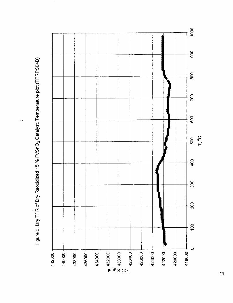
Figures 1-3 show the results for dry reduction, dry re-oxidation, and dry reduction of the re-oxidized
catalyst. Two distinct redt, ction peaks, one at around 130 °C and the other at around 425 °C are
observed for the fresh catalyst (Figure 1). The small jump in the TCD signal just above 500 °C is
probably due to the flow disturbance introduced by the addition of liquid nitrogen to the cold trap to
re-freeze the propanol. The addition of liquid nitrogen to the trap always produced severe
fluctuations in the TCD signal, which in most cases returned to normal. Occasionally, the condensed
moisture froze and partially or totally blocked the flow path, which resulted in permanent flow
disturbance until the cold i:rap is heated to restore the flow. To illustrate this, the points of liquid
nitrogen additions and total flow path blockage are shown on some of the TPR curves. Dry re-
oxidation of the reduced catalyst is seen to be slow, with a rate proportional to the temperature
indicating mass transfer control of this process (Figure 2). The TPR of the re-oxidized catalyst
exhibits two distinct reduction regions, a wide peak around 350 °C, and an incomplete high
temperature peak, which :;tarts at around 750 °C. The shape of the low-temperature peak also
suggests mass transfer limitation at temperatures below 300 °C. Figures 4 and 5 show the amount of
hydrogen consumption by _:he _esh and re-oxidized catalysts. From these graphs it can be observed
that the oxidation-reductioTl capacity of the catalyst has decreased significantly when the catalyst was
subjected to dry TPR up to about 1000 o C. This may be due to the loss of OH groups that were

attachedto tin oxide, but since Figures 2 and 3 indicate the presence of mass transfer limitations, the
deterioration of the low temperature reduction-oxidation activity may be, at least partially, due to the
loss of active sites due to sintering at the high temperatures involved.
Figures 6-8 show the results for dry reduction, wet re-oxidation, and dry reduction of the re-oxidized
catalyst. Figure 6 shows the results of a TPR under the same conditions of those of Figure 1 and
gives an indication of the reproducibility of the results. Comparison of Figure 7 with Figure 2 shows
a higher oxidation rale during wet oxidation, which starts after 500 °C with a peak at around 725 °C.
The higher oxidation rate is also confirmed by the larger reduction peaks that were obtained during
subsequent dry reduction (Figure 8) compared to those shown in Figure 3. A more quantitative
indication of the reproducibility of the results can be obtained by comparing the hydrogen
consumption figures :_hown in Figures 4 and 9. Reproducibility of the total hydrogen consumption is
quite good (8.18 ml STP H2 versus 8.25 ml). The slight discrepancy (1.87 ml STP versus 1.29 ml) in
the amounts of hydrogen consumption corresponding to the low temperature reduction peak is
mainly due to the placement of the baseline, which is complicated by the disturbances introduced
during the addition o f liquid nitrogen to the cold trap as discussed above. In order to obtain a more
reasonable quantitative result, the flow disturbance seen in Figure 8 is omitted in Figure 10 and the
results are reported as estimates. Figure 10 shows that the low temperature reduction peak after wet
re-oxidation is about 2.5 times larger than the low temperature reduction peak obtained after dry re-
oxidation. It is also ebserved that a more significmat increase in the high temperature reduction is
obtained following _ et re-oxidation.
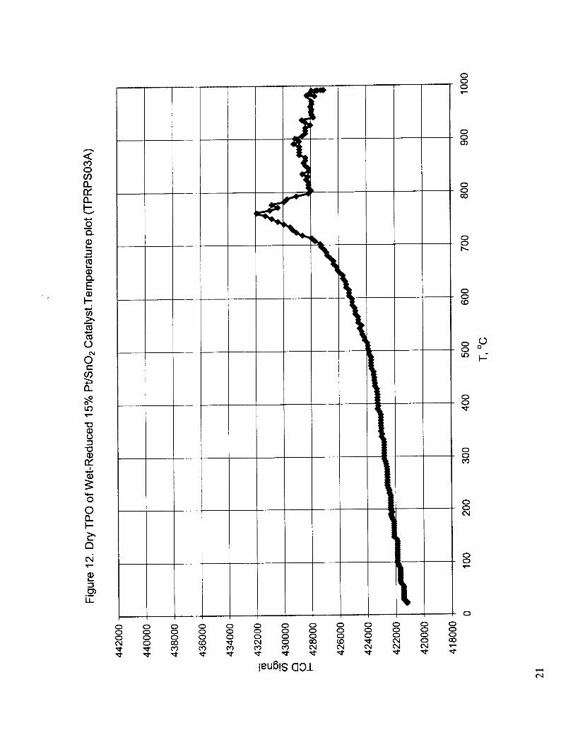
Figures 11-13 preseI_t the results for the wet reduction, dry re-oxidation, and wet reduction of the re-
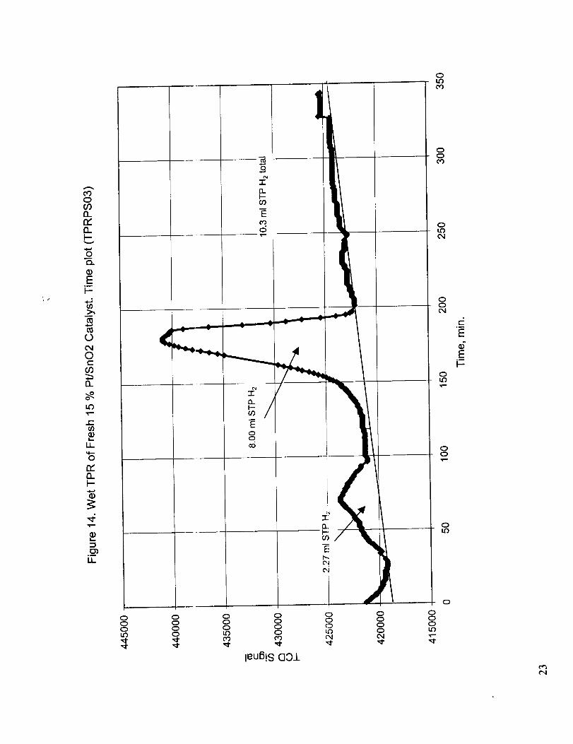
oxidized catalyst and Figures 14 and 15 provides quantitative results for the wet reduction of the
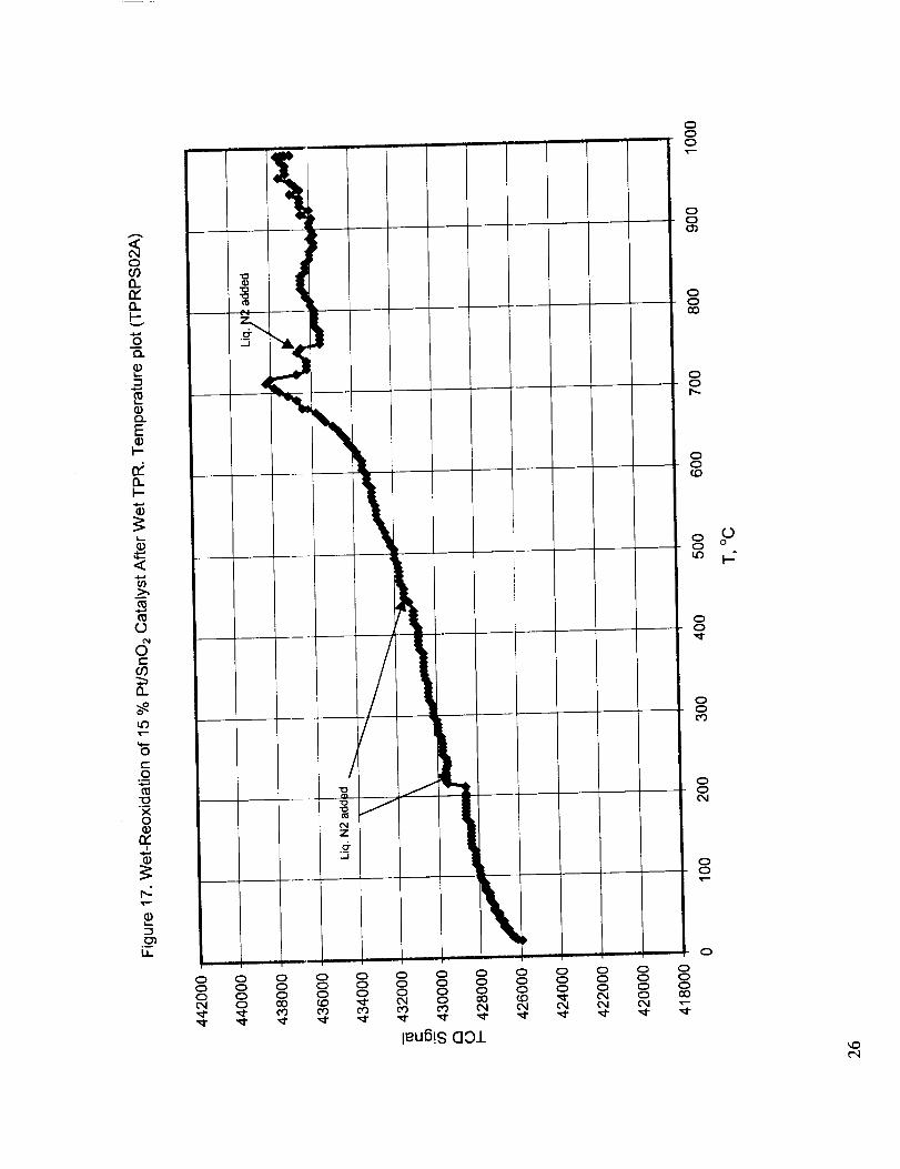
fresh and dry re-oxidized catalyst. Figures 16-20 present the corresponding results for the case of wet
reduction, wet re-oxidation, and wet reduction. Comparison of Figures 11 and 16 with Figures 1 and
6 show that wet redu,ztion does not change the position of the low temperature reduction peak and
moves the high temperature reduction peak to slightly higher temperature (about 30 °C). The
oxidation peak observed at 760 °C in Figure 12 during dry re-oxidation of wet reduced catalyst is
similar to the oxidation peak observed in Figure 7 for the wet re-oxidation of dry reduced catalyst,
but occurs at a slight ly higher temperature. The quantitative results presented in Figures 9 and 14
indicate that the amount of wet reduction obtained both at low temperature (around 150 °C) and high
temperature (around 450 °C) is somewhat higher than those for the dry reduction. On the other hand,
the wet TPR of dry re-oxidized catalyst shown in Figure 13 is significantly different compared to the
dry TPR of the wet re-oxidized catalyst given in Figure 8. The low temperature peak observed at 150
°C during the wet or dry TPR of the fresh catalyst re-appears in the wet reduction of the dry re-
oxidized catalyst, and the high temperature reduction peak that was seen starting around 750 °C in
Figures 3 and 8, sta..-ts at around 500 °C in Figure 13 and peaks at around 850 °C. When the
quantitative results presented in Figures 10 and 15 are compared, it is seen that the total amounts of
reduction of the re-oxidized catalyst in both cases are comparable.The results shown in Figures 16-
20 for the wet reduction, wet re-oxidation case are almost identical to the results of wet reduction,
dry re-oxidation case presented in Figures 11-15.
In summary, the pre_ence of water vapor during the reduction and/or re-oxidation of the catalyst
plays a significant role in retaining the reduction-oxidation activity of the catalyst. While about the
same amount of reduction is obtained for dry reduction-wet re-oxidation and wet reduction-dry or
wet re-oxidation cases, the reduction temperatures are significantly lower for the wet reduction cases.
4

From these observations it may be tentatively concluded that the effect of water vapor during
reduction is to reduce sintering and retain reduction and oxidation activity at lower temperatures
while the effect of water vapor during re-oxidation may be attributed to the enhancement of the
oxidation rate by the presence of OH groups.
TPR of Other Catalysts Prepared by NASA/LaRC
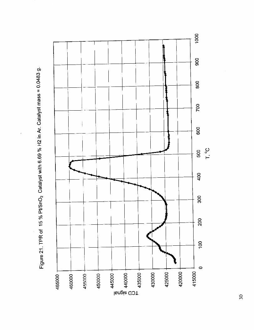
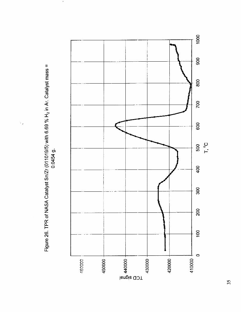
Figure 21 shows the dry TI'R of the baseline 15% Pt/SnO2 catalyst with hydrogen and Figures 22-26show the TPR curves for w_rious combinations of tin oxide with the oxides of cerium, zirconium
and aluminum.
Table 1. Summary ot TPR Results for Various Tin Oxide-Based Mixed Oxide Catalysts
Catalyst
15% Pt/SnOz ..
Sn (011019/1)
SrgCe (011019/2)
SrgCe/Zr
(011019/3)SrgCe/Zr/A1
(011019/4)
Sn/Zr (011019/5)
First ?eak Second Peak
Temp. Range
(pk temp), °C
280-544 (456)
440--690 (613)500-760 (642)
First Peak Size 2ndPeak Size Total reduction
ml STP HJ100
mg cat.2.68
ml STP H2/
100 mg ca t.7.93
ml STP HJ
100 mg cat.10.6
1.36 12.4 13.8
2.05 15.6
13.3
Temp. Range
(pk tO), °C
, 44-222 (148)
150-350(250)175-43 7 (248,
33o)135-330 (238) 390-706 (540) 2.24
13.5
11.1
152-440 (304) 447-840 (600) 2.43 4.65 7.08
150-470 (290) 490-670 (600) 5.78 12.3 18.1
Since the amount of tin o _ide in each mixture is different, relative amounts of reduction cannot be
observed directly from these figures. Therefore, the quantitative results are calculated and presented
in Table 1 along with the information about the reduction peak temperatures. The lowest reduction
peak temperatures are obtained with the Pt-containing baseline catalyst. The other catalysts have
significantly higher peak temperatures, low around 300 °C and high around 600 °C, with the
exception of Srt/ Ce/Zr catalyst, which has reduction peaks around 240 °C and 540 °C. An
interesting observation from the table is the increase in the amounts of both low and high
temperature reductions for Sn/Zr catalyst and the increase in the amount of high temperature
reduction for the Sn/Ce This can be attributed to the ability to create oxygen vacancies and high
oxygen mobility of the cerium and zirconium oxides.
These observations make the investigation of the enhancement of the activity and high temperature stabilityof tin oxide-based catalysts by the introduction of appropriate metal oxides an attractive topic for future
investigations.
TPD of Other Catalysts Prepared by NASA/LaRC
For these experiments the catalyst sample was subjected to various pretreatments. Pretreatments with
dry gases consisted of 3owing a gas stream (He, He+10.1% CO, He+3.6% 02) over the catalyst
sample for two hours at 50 °C. Pretreatment with wet He involved flowing dry He over the catalyst
for 2 hours followed b- a 10-minute flow of He bubbled through de- ionized water at 25 °C. All
pretreatments were followed by He flow over the catalyst at 50 °C for two hours to desorb the
physically adsorbed sp_.cies. This was followed by the injection of 1-ml doses of the CO-containing

gas into the carrier gas str.-am at 30 °C. This dosing was continued until the peak areas stayed
relatively constant. Only CO2 was observed in the exit gas, using a gas chromatograph equipped with
a thermal conductivity detector, indicating that the catalyst was very effective in oxidizing CO. The
CO2 peaks eventually react_ed a relatively constant area, which was smaller than the CO peak of the
feed.
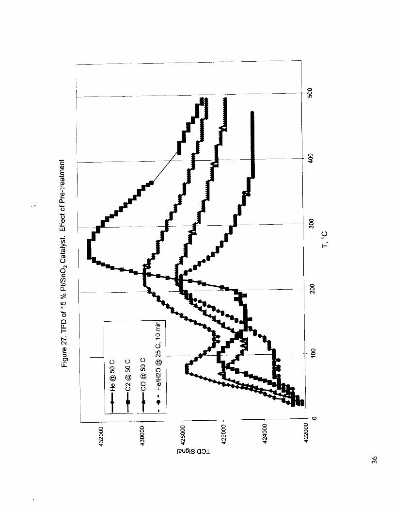
Figure 27 shows the temperature programmed desorption results for catalyst samples subjected to
various pretreatments. The TPD results were different alter the pretreatment of the catalyst in He,
CO, 02, and wet He. Two desorption peaks were obtained with the catalysts pretreated with dry
gases, while only the first desorption peak was obtained with the catalyst pretreated with wet He.
The low temperature peak observed around 75 °C for dry He and CO pre-treatment and at 100 °C for
02 pre-treatment was tentatively attributed to the desorption of physically adsorbed species. The
absence of this low temperature peak for the TPD of the catalyst sample pretreated with wet He can
be explained by the filling of active sites with adsorbed water. Due to the presence of the cold trap
the desorption of water is not observed. The high temperature peak observed around 225-250 °C was
attributed to the formation and subsequent desorption of CO2. Two possible mechanisms may be
possible for the formation of CO2. One may be through the reaction of a CO molecule adsorbed on a
platinum site with the lattice oxygen of an adjacent tin oxide site. Another route to CO2 formation
may be the formation of surface carbonates at the metal oxide sites and the subsequent
decomposition of these surface carbonates. The slightly elevated temperature of the second peak for
oxygen pretreatment will be consistent with this second mechanism. These arguments are based on
the gas chromatographic ar:alysis ofdesorption products, which indicated the presence of only CO2;
but the analysis of the desorption products were not detailed enough to arrive at a more definite
conclusion. Figure 28 shows the effect ofpretreatment temperature on the TPD results after CO pre-
treatment. The low tempelature desorption peak is absent for pretreatment at 125 °C because the
pretreatment temperature is higher than the temperature for the desorption of physically adsorbed
species. The difference in tiae shapes of the desorption curves for the 50 °C and 125 °C pre-treatment
with CO may be due to the decrease of the importance of CO2 formation through the first mechanism
as the result of the decrea:;e in the amount of CO adsorbing at Pt sites at the high pre-treatment
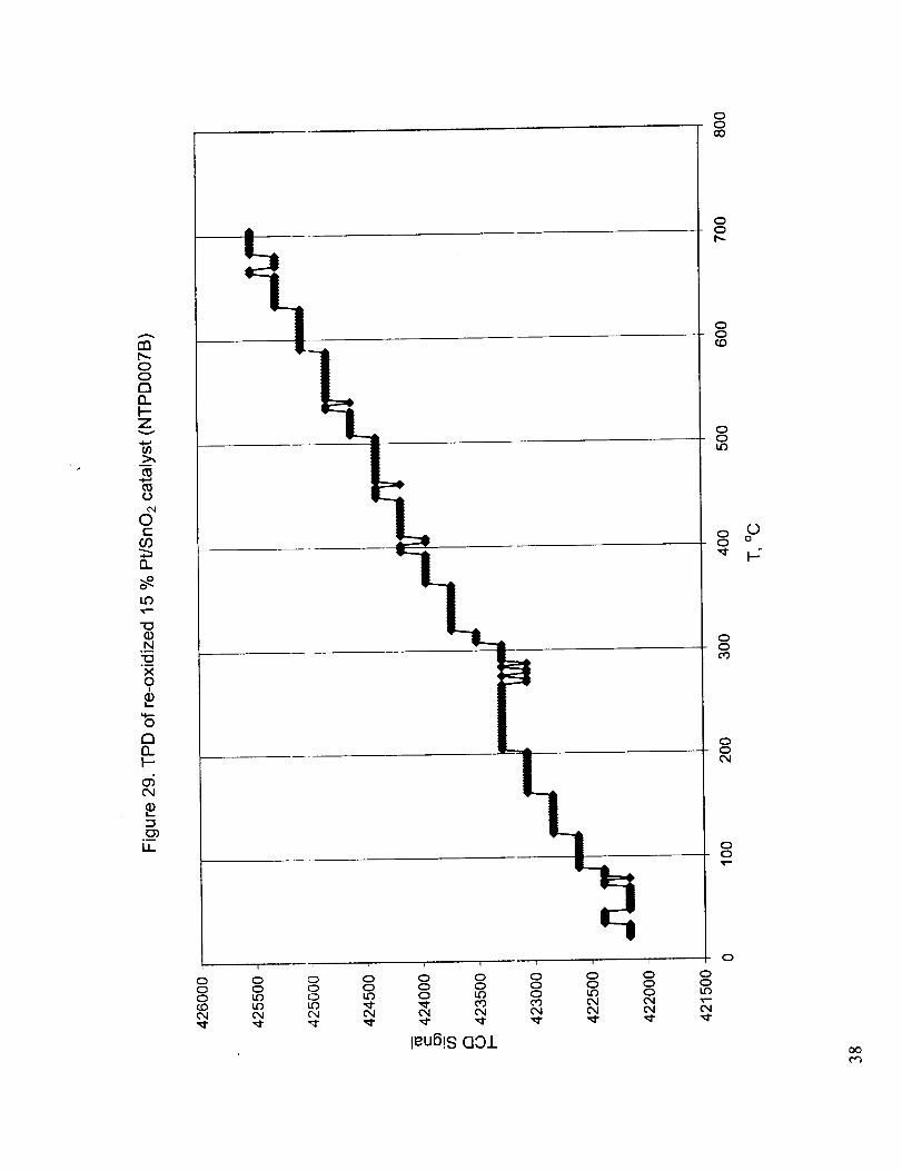
temperature. After the TPD runs up to 600 °C the catalysts were re-oxidized with oxygen at 600 °C
and the re-oxidized catalysts produced TPD curves with no peaks indicating very slow, almost
constant rate desorption (Figure 29).
Temperature Programmed Reaction Studies with GC-MS Analyzer
Since the results of the gas chromatographic analyses were not sufficiently sensitive to provide an
accurate gas compositions, it was decided to replace the gas chromatograph with a new GC-mass
spectrometer system for more detailed product gas analysis and to repeat the CO chemisorption-TPD
runs under He-O2 mixture to obtain more insight into the processes occurring on the catalyst.
Figure 30 shows the relati','e amounts of CO and C O2 obtained when the fresh 15 % Pt/SnO2 catalyst
was subjected to repeated 0.993 ml doses of 10.1% CO in He under flowing He at 50 °C. The
corresponding thermal conductivity detector peak areas indicating the total gas composition change
are also shown. It is seen tltat negligible amounts of CO are present in the product gases and almost
all the injected CO is oxidized to CO2 possibly through the formation and subsequent decomposition
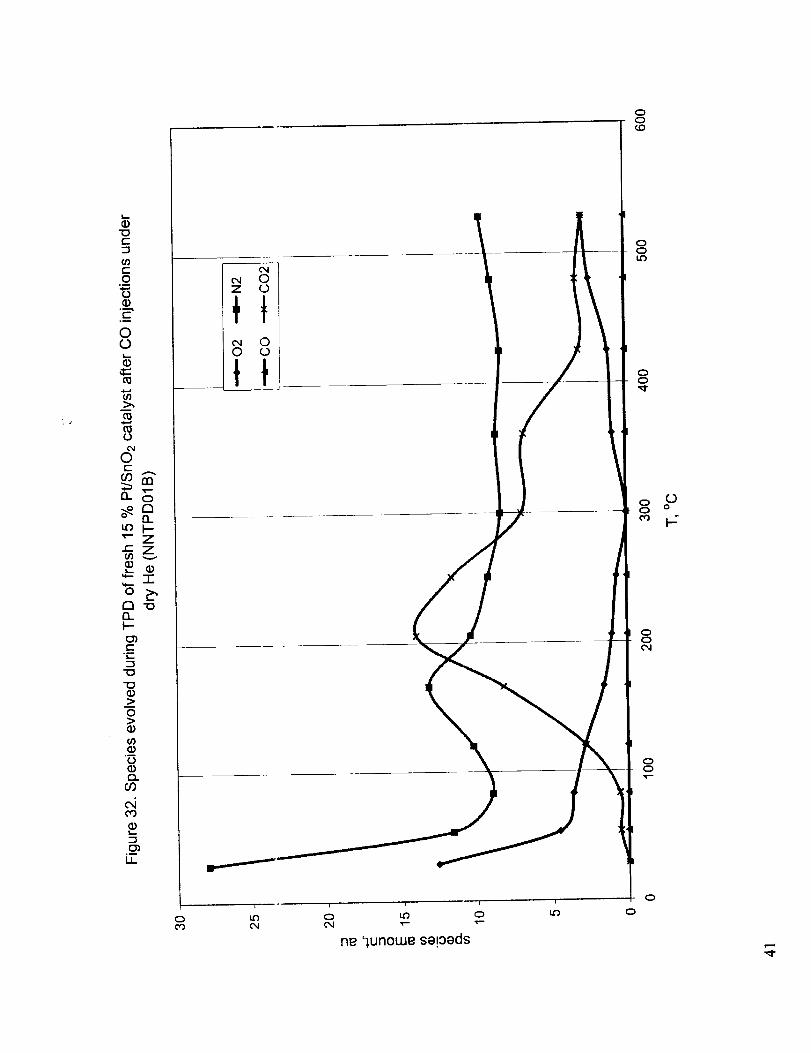
of tin carbonates. Figure 3 l shows the TPD curve obtained after the CO injections of Figure 30,
while the relative amounts of the evolved species are presented in Figure 32. These figures show that
the first TPD peak below 100 °C is due to the desorption of adsorbed air and moisture and the peak
around 220 °C is due to the CO2 evolution as the result of the dissociation of surface carbonate
6

species.Nosignificantquaz_titiesof COweredetected.FollowingtheTPDof Figure31,TPOof thecatalystwasperformedupto 530°C.Figure33showstherelativeamountsof COandCO2obtainedwhenthere-oxidizedcatalbstwassubjectedto repeated0.993ml dosesof 10.1% CO in Heunderflowing Heat 50°C.Deactivationof thecatalystis clearlyvisible. A significantamountof CO isobservedalongwith theC()2(theratioof COto CO2is about2:3).Thefollowing TPD producedaflat curveandtheanalysisof thegasesdid not showanypresenceof CO or CO2 indicating the
absence of carbonate species on the surface. This observation combined with Figure 33 implies that
not all CO z was formed b2y the dissociation of the carbonates, but the reduced catalyst has some
activity for direct CO oxidation as well, possibly involving Pt surface sites.
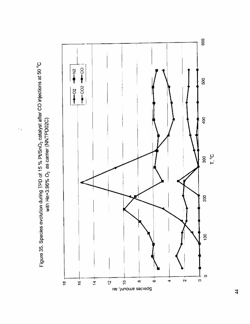
Figure 34 shows the TPD c_Jrve obtained after CO chemisorption under a carrier gas containing 3.6
% O2 in He. This is very similar to Figure 32 except that the observed peak temperature is slightly
higher. The species evolved during TPD is presented in Figure 35. The most important observation
from this figure is the small CO peak occurring at the same temperature as the CO 2 peak. Figures 36
and 37 show the species preduced with fresh and used catalyst during the injection of 0.993 ml doses
of CO under an oxygen-containing gas stream at 50 °C, respectively. With the fresh catalyst no CO is
observed and the CO2 evohation decreases slightly to a steady state value atter about 6 injections. On
the other hand, with the used catalyst the COz evolution increases from zero to about the same steady
state value after about 14 injections, while the observed CO, which is initially about one third of the
steady state CO2 value, decreases continuously with each CO dose. Apparently, presence of oxygen
in the feed inhibits the deactivation of the catalyst, which maintains significant activity even when
heated up to 530 °C. This may be attributed either to the involvement of gaseous oxygen in the
oxidation of CO on the Pt sites, or to the enhancement of the CO oxidation by the oxygen in the gas
phase, which fills the oxygt;n vacancies created in the tin oxide lattice when a CO molecule on the Pt
surface reacts with the lattice oxygen of an adjacent metal oxide site.
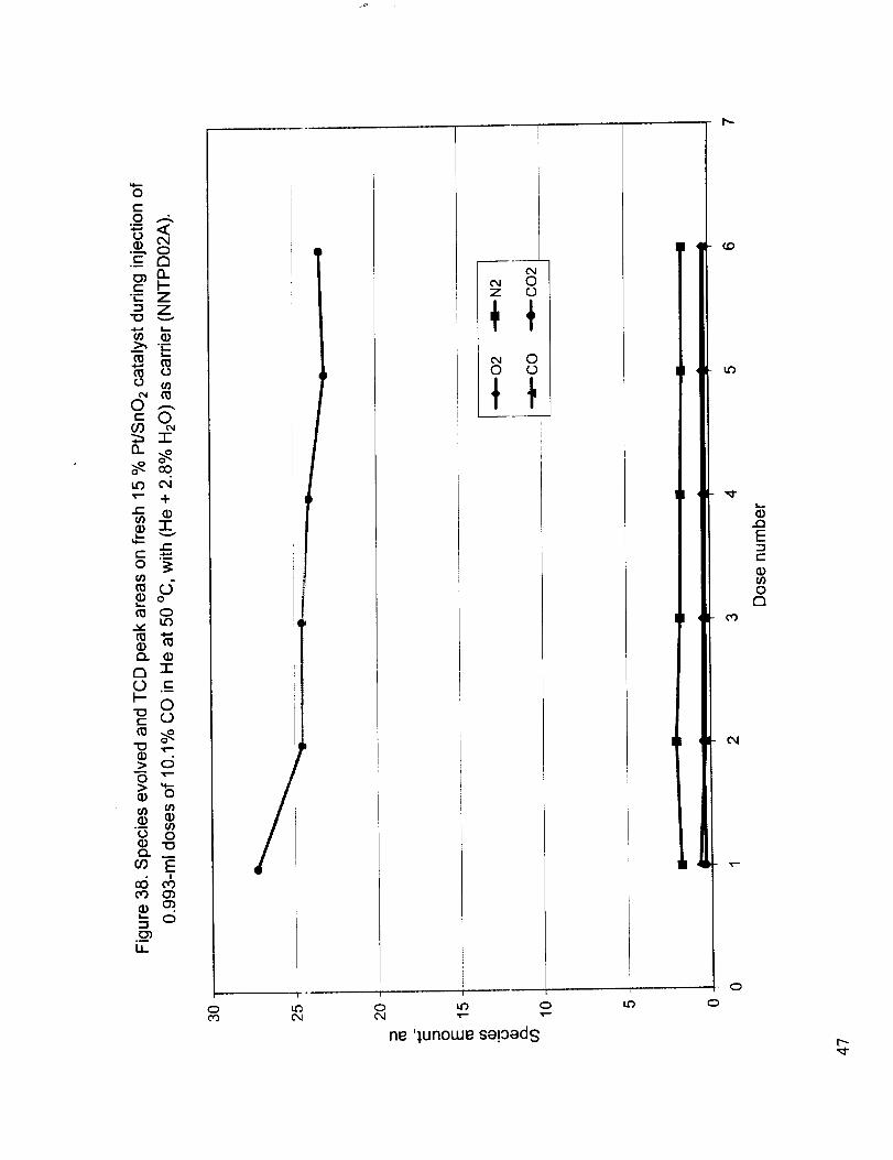
Figure 38 shows the species evolved during 0.993-ml injections of 10.1% CO in He at 50 °C into a
carrier gas stream of moist He containing 2,8 % water vapor. As with the other carrier gas streams
almost all CO is oxidized to CO2. The amount of CO observed is slightly more than those when dry
and oxygen-containing helium is used as the carder gas stream. Figure 39 shows the TPD curve
obtained after CO chemisc, rption under a carrier gas containing 2.8% H20 in He. The desorption
peak occurs at the same temperature as with dry He, but the size of the peak is significantly smaller.
The species evolved during desorption is very similar to those observed after CO injections under
oxygen-containing carrier gas, but the amounts are much smaller (Figure 40). From these
observations it can be coacluded that presence of water during CO injections inhibit surface
carbonate formation, thus trte much smaller desorption peak, but enhance direct CO oxidation on the
Pt sites with water supplyirig the oxygen by some sort of water gas shift mechanism, as evidenced by
the high conversion to CO, shown in Figure 38.
CONCLUSIONS
The main conclusion from the TPR experiments is that the presence of water during reduction, re-
oxidation, or both helps tt:e 15 % Pt/SnO2 catalyst to retain its oxidation-reduction activity even
when heated up to about 1000 °C. This is attributed to the presence of hydroxyl groups attached to
tin oxide, which may facil tate the re-oxidation of the reduced oxide.
The TPD and TPRn result,,; indicate the existence of two different mechanisms for the oxidation of
CO on the

15 % Pt/SnO2 catalyst. One mainly involves the platinum sites and leads to the oxidation of adsorbed
CO either by the lattice oxygen supplied by a neighboring tin oxide site or an adsorbed oxygen atom,
the second going through the formation of surface carbonates and their subsequent desorption. The
extremely high conversion rate for the flesh catalyst during CO injections and the relatively lower conversion
rate on the re-oxidized cataly,,;t indicate the importance of the first mechanism. The second mechanism is the
primary source of CO2 that is observed during temperature programmed desorption.
Both the presence of oxygen or water facilitates the first mechanism by providing external oxygen. High
temperature reduction appea,s to kill the catalyst's activity for the carbonate formation but the catalystmaintains its ability to promc.te CO oxidation via the first mechanism.
Presence of water vapor during CO oxidation diminishes carbonate formation significantly. This is rather
disappointing because water vapor was also found to facilitate the re-oxidation of the catalyst and help retainits reduction-oxidation activity. This indicates the need for finding an appropriate additive to retain the
catalyst activity in high temperature applications. Oxides like ceria, which possess a large oxygen capacity,
high oxygen mobility, and file ability to form oxygen vacancies, are prime candidates for this purpose.Preliminary TPR studies presented in this report for the effect of some additives indicate that results with
ceria and zirconia are very promising. Finding an optimum catalyst composition will be the focus of futureactivities.
8

FIGURES
Figure 1. Dry TPR of fresh 1: % Pt/SnO2 catalyst. Temperature plot.
Figure 2. Dry re-oxidation of dry reduced 15 % PffSnO2 catalyst. Temperature plot.
Figure 3. Dry TPR of dry re-c, xidized 15 % Pt/SnO2catalyst. Tempera_re plot.Figure 4. Dry TPR of fresh 15 % Pt/SnO2 catalyst.. Time plot
Figure 5. Dry TPR of dry re-_,xidized 15 % Pt/SnO2 catalyst. Time plotFigure
FigureFigure
FigureFigure
FigureFigure
FigureFigure
FigureFigure
FigureFigure
FigureFigure
FigureFigure
FigureFigureFigure
FigureFigure
Figure
FigureFigure
FigureFigure
Figure
FigureFigure
Figure
Figure
Figure
Figure
Figure
6. Dry TPR of fresh 15; % Pt/SnO2 catalyst. Temperature plot.7. Wet TPO of dry reduced 15 % Pt/SnO2 catalyst. Temperature plot.
8. Dry TPR of wet re-oxidized 15 % Pt/SnO2 catalyst. Temperature plot.9. Dry TPR of fresh 15 % Pt/SnO2 catalyst. Time plot
10. Dry TPR of wet re-oxidized 15 % Pt/SnO2 catalyst. Time plot11. Wet TPR of fresh 15 % Pt/SnO2 catalyst. Temperature plot.
12. Dry TPO of wet reduced 15 % PffSnO2 catalyst. Temperature plot.13. Wet TPR of wet reduced, dry re-oxidized 15 % Pt/SnO2 catalyst. Temperature plot.
14. Wet TPR of fresh 15 % Pt/SnO2 catalyst. Time plot15. Wet TPR of wet reduced, dry re-oxidized 15 % Pt/SnO2 catalyst. Time plot
16. Wet TPR of fresh 15 % Pt/SnO2 catalyst. Temperature plot.17. Wet TPO of wet reduced 15 % Pt/SnO2 catalyst. Temperature plot.18. Wet TPR of wet re duced, wet re-oxidized 15 % Pt/SnO2 catalyst. Temperature plot.
19. Wet TPR of fresh 15 % Pt/SnO2 catalyst. Time plot20. Wet TPR of wet reduced, wet re-oxidized 15 % Pt/SnO2 catalyst. Time plot
21. TPR of 15 % Pt/SnO2 catalyst with 6.69% H2 in At.22. TPR of NASA catalyst SnEH only (011019/1) with 6.69% H2 in At.
23. TPR of NASA catalyst Sn/Ce (011019/2) with 6.69% H2 in Ar.24. TPR of NASA catalyst Sn/Ce/Zr (011019/3) with 6.69% H2 in At.25. TPR of NASA catalyst SrgCe/Zr/A1 (011019/4) w_th 6.69% H2 in Ar.
26. TPR of NASA catalyst SrdZr (011019/5) with 6.69% H2 in Ar.27. TPD of 15 % Pt/SlaO2 catalyst. Effect of pre-treatment.28. TPD of 15 % Pt/S_IO2 catalyst after pre-treatment with 10.1% CO in He. Effect ofpre-
treatment temperature.29. TPD of re-oxidized 15 % Pt/SnO2 catalyst.
30. Species evolved a_ld TCD peak areas on fresh 15 % Pt/SnO2 catalyst during injection of0.993-ml doses of 10.1% CO in He at 50 °C, with He as carrier.
31. TPD of fresh 15 _J Pt/SnO2 catalyst after CO injections at 50 °C, with He as carrier.
32. Species evolved daring TPD of 15 % Pt/SnO2 catalyst after CO injections under dry He.
33. Species evolved a_ad TCD peak areas on 15 % Pt/SnO2 catalyst re-oxidized after CO sorptionand TPD to 530 "C, during injection of 0.993-ml doses of 10.1% CO in He with He asearner.
34. TPD of fresh 15 o; Pt/SnO2 catalyst after CO injections at 50 °C, with He+ 3.6% 0 2 as carrier.35. Species evolved during TPD of 15 % Pt/SnO2 catalyst after CO injections under He+3.6% 02
as carrier.
36. Species evolved and TCD peak areas on fresh 15 % Pt/SnO2 catalyst during injection of0.993-ml doses t,f 10.1% CO in He at 50 °C, with He+3.6% O5 as carrier.
37. Species evolved and TCD peak areas during re-dosing with CO at 50 °C after TPD to 530 °Cwith He+3.6% Ch as carrier.
38. Species evolved and TCD peak areas on fresh 15 % Pt/SnO2 catalyst during injection of0.993-ml doses of 10.1% CO in He at 50 °C, with He+2.8% H20 as carrier.
39. TPD of fresh 15 o; PtJSnO2 catalyst after CO injections at 50 °C, with He+ 2.8% H20 ascarrier.
40. Species evolved during TPD of 15 % Pt/SnO2 catalyst after CO injections at 50 °C, withHe+3.6% 02 as carrier.

ooo
) ,-
0cOD_n-D_
oQ.
<D
O.
E
_0
0
oc-cO
D_
LO
c-
(DI,-
0
r_
rn°
u_
--i
oo
oo00
oo
oo
oo
ooco
oo
oo
o
0 0 0 C; 0 0 0 0 0 0 0 0 00 0 0 C' 0 0 0 0 0 0 0 0 00 0 0 C_ 0 0 0 0 0 0 0 0 0
T-
leu6!s GOI

oO.
-i
E
I,-
0
0
CO
a_
_<
_- 0O3
"o I--v
n_
0
0
0°m
X0(I)
rY
a
Z3.__LI_ !
0 0 0 0 0 0 (_ 0 0 0 C3 0 (_0 0 0 0 0 0 0 0 0 0 C) 0 00 0 0 0 0 0 0 0 0 0 _ 0 0
_" _f" 03 ("3 CO CO Or) _ _ _ _ _ _--
leU6!SO:Z)L
000
00or)
00
00
00tO
ooo o
00
00cO
00c_
0o
0
000
J
rn0
B_r_nt--v
0
Q.
I,,..
-I
0..
E
I-
0
0t-
co
o.
o_LO
X0
ry
121
0
n,
i-
.__
Jr
00O_
00cO
00
00
0o°o
00
0oco
o0
00
0
0 0 0 0 0 0 0 0 0 0 0 0 00 0 0 0 0 0 0 0 0 0 0 0 00 0 0 0 0 0 0 0 0 0 0 0 0¢Xl 0 CO tJ:) ,_" ¢Xl 0 O0 t4_ _ _ 0 O0
leU6!8 C]O_L

llii
i
o
o3
000nty13_I-
0
O.
E°_
0040t-
OO
Q_
t-
Ll-
0
tyO_h-
rn
p
O)
LL.
0 0 c)0 0 c)0 0 c)
04 c)co cO 0-)
04i in m
:£:£n D..I-- 1--03 o3
E E
•-- u3c5o_
:£13_I--O3 j
EcO03
,,t--
e.4,._ _e." 9
"1-
o_,Doco
c_ o o oo O o Oc) o o o
04 c'xl c',,I 04
leU6!S (]D.L
o0co
oLOO4
00
0
o0
° ki
o
O O O O OO O O O OO O O O OO CO t..O _ 04
t-°_
Ee"EI-

0
O0
a.
v
0
Q.
E°--
>,
oC_
0
O0
LO
"0
N
X0Q)n-
a
o
n,
u6
._
U_
:ff13.t--
E
13_I---
I---
,-:i
i
OOO
O OO OO O
o3 c'q
leu6!sC]3J_
000cOo4
0_,_cO
00
)0t_
00
0(P)
00
0LO
0
000QO
e-°_
E
E°_
b-

0
cO13_n,'13.
v
0
Q.
'-I
E(].)I-
2,
0
ot-
OO
n
¢-
(I)
U-
0
n,"Q_F-
(:3
(.6
LL
/"c"I{:
z
,,._ ,---,-W_-'''" I'''''
I
r
/
__......-
/0
00
oo0',1"-
00
00
o0b.-
oocO
0o
o0
ooc_
oo
., o
0 0 0 0 0 0 0 C) 0 0 0 0 00 0 0 0 0 0 0 C) 0 0 0 0 00 0 0 0 0 0 0 0 0 0 0 _ 0
leu61s (301

%..,.
00313_n-D_
v
0
o
{3.
E
tO0
0t-
03
3
r_
r_
0
0D_
U_
o o _ o oo o o o oo o o o o¢xl o 00 (.(3
I
I
_0
d..
iI
I
z
I
o 0 o oo 0 o o04 _ cO t4O
leu6!s (301
!0 0 0 00 0 0 00 0 0 0
000
00O_
00CO
00
00_0
0o o
o0
oo03
0o
oo
o
_D

_n
0
D_n_D_
v
0Q_
E
0
0t-_0
D_
Lo
X0Q)n,
Q)
0
r_a.F--
a
0)U_
o oo oo o
o•_ _._- _-
C) 0 0 0 0 0 0 0 0 0 0C_ 0 0 0 0 0 0 0 0 0 0C) 0 0 0 0 0 0 0 0 0 0a:) ¢0 _ 04 0 oO ¢0 '_' C_l 0 c_C_) CO co Co Co o,l _ C_ C_ C_ v-
leU6!S O0.L
ooo
oo
ooco
oob..
oo
0oo o
oo
ooco
oo
oo
o

00
0co(3_OC0_Y-V
.¢.,a
0
O.
EY--,e-,#
,w.,a
0C_0c"GO
CL
LO
e-
LL
0
n-il_y--
c_
oi
o
U_
0 0 0 00 0 C) 00 0 0 004 0 cO CO
k
v v
:_' p,
_. f_4
1-
t-
E
°
0
00
0
0
0
00
0
0
0 0 0 C) 0 0 0 00 0 0 0 0 0 0 00 0 0 0 0 0 0 C)
O0 CO ¢9 04 (NI _/ _ 04
leU6!S OOl
°--
E
E
oo

rn
0O0B_n_B_
V
"T
v
o
(D
E°_
0t-O0
D_
LO
X0
n,
o;
on-o_
a
d
--I
°--
u..
o
:ff13_
if?
E
6
t )
I--
ECD
I--
v
coo
\i
,/!I:
ooo00o9,_-
o oo 0o o00 00o3
leu6!8 (391
o0oco
,_-
0oocO
0o
oLO00
0ocO
oLOo4
t-.--
o E
E
oLO
o0
o
o

lo0o
cO0conr_np-
0
Q.
QQ_
Ep-
0
(D
co
n
tO
0
r_n
(D
O3o_
I
J
\
L
r
0 0 0 0 00 0 _ 0 00 0 _ 0 O
00O_
0000
00
00
0
00
0
O0
0
0 0 0 0 0 0 0 Q0 0 0 0 Q 0 0 0O _ 0 O Q 0 0
leU6!SGO.I.
0o
0
CO0
O0
8_
n_D_
V
0
Q.
E
0O_
0
cO
D_
0-s
n_
0
0D_
r_
LL.
'r
L
o0o
o0
0ocO
0o
0
_0
C)
00
o0co
0oo4
00
o
o 0 o CD 0 0 0 0 0 0 0 0 00 0 0 0 0 0 0 0 0 0 0 0 00 0 0 0 0 0 0 0 0 0 0 0 0
leu6!£ (301

O
Q.
E
_D
Occo
D_
.N
X
n
n__5
O
D_D_
05
U-
O O O O OO O o O oO O O O O
, !
\
OOO
OO
OocO
OO
OO
ON0
o0
00
OO
OO
O
0 0 0 0 0 0 0 00 0 0 0 0 0 0 00 0 0 0 0 0 0 0¢xl C_ cO _0 _ Cx.I 0 aO
leu6!sO0.L
COOO3ID_rY&.I-
O
Q..
E°_
I-
OO,IOEO3
8_
LO
J=
LL
O
r_I1.I-
1.1_
o
n1-00
E
o
OOOtO
OOOO
O OO OO OLO O¢O 03
leu6!s O3_L
OOOI.O
0
o3
OO
0I._
00
0
00
0
0
t-°_
E
e"E._

J
OQ.
EI--
>.,
oO4Of-cO
n
N _._
oO
rY
al-v
"10
o
rY
O
rYnF--
LL
E¢0
nI-
E
.¢_ •v,-
I--
.,-3
c_c)c)cooo
o oo oo o
co o,I
leu6!sGO1
ooocoo4
oo
o
ooco
o
o4
o
o
o
oo
o
o
oooao
oI
E
EI-
cq

OO313_r_D_
v
O
r_
E
O
Oc-O0
0_
o_t_
LL
O
n_D_
LL
\
JJ
JJ
Av 4
° ICD.Q.O
!=
z
Fk
O O O O O O O O O O O O OO O O O O O O O O O O O OO O O O O O O O O O O O O
leU6!£GOI
ooo
ooo_
ooco
oo
oo
Oo° o
oo
ooco
oo
oo
o
000a.n"(%F-v
Q.
Q.
E
I.-
>,
0
(-.cO
0
c0o_
x0Q)OC
r_
U-
lluu
3
!
/i
I
00
' 0
oo
o0

0O.
E
t_
0
ot-
O0
D_
_O
.N
0
" v
-o"0
"0
r_
0
r_n
06
°_
IJ_
"0
z
/"10
"rl
t_
z
_J
,)
J r
1
).
k
0 0 0 0 0 0 0 0 0 0 0 0 00 0 0 0 0 0 0 0 0 0 0 0 00 0 0 0 0 0 0 0 0 0 0 0 0
leu6{s(]O.L
000
00
00_0
00
00_0
oooo
o0
00co
00
00
0

C_0Or)ft.n,"
F-v
0
EF-
0O4
0(.-0')
e-
LL
0
0Cfl_F.-
oi
I,.,.
LL.
C_
o
o Q,
"I- U)
.,.-,
co T-
A
v
TC}-I'-OrJ
E
. .=_.4,_---,--,J
/ "iJ
O0
0
0Q
o
o
oo
o
d
EdE

/
0Q.
EI-
0
0
CO
15.
L_
"0
.N_
x0
r_.,Z,'
"0
n_
0
Q.h--
d(NQ
U-
CO
,f
00
CrJ
/
h-if)
-g
b,-
t_
/, r
ooo
o oo oo oco ¢0co _1
10qmXs 1210.1.
00
cN
ooo
oo
o
oo
o
o
o
oo
o
o
°_
E
dEI--
t'N
d_
cO
0
0
II
E
e-°_
I
CD
e,-
ff)
C4
o
LO
0
!---
.__LI_
I
I
000
00
0000
00
00cO
o
c)0
00cO
0004
00
0
0 0 0 0 0 0 0 0 0 0 00 0 0 0 0 0 0 0 0 0 00 o o,, o 0 0 0 0 0 0 0
_D t.O L£. LO _ _ CO O0 04 04 .r-
l_U6!S1301
00
0

II
E
(g
OL
e-°_
Oq"1-
o_O_CO
_6c-
O_
od),r*" O0T'- I_
v
>o.
O
"1-iiie-
cO,4==D
O
cO
Z
O
n_0_F--cqC_
-s
LL
C
.,,,,,=,.,,,=,=,==-_
ooo
ooO')
o00
oo
Z
I
,f
OOt,O
OO
00¢0
00
00
0
0000
0 0 00 0 0o 0 00 0 0
leUf!SGO.L
OOOo¢0
OOOoO4

O_
O
c_II
E
cD
<c-
°_
('4
n-
O_CO
_6t-
O_
O_
O
O
C
O9
0_
t_
<t_
<Z
O
n_D_
_4
r
q
t,
OOoO
OOOO
O OO Oo oO O
leU6!S (]OJ.
00
000
00
00
00r_
00cO
oQ o
00
OOcO
OO
OO
O
OOOO

II
(/)
E
t/)
0
c-
"i-
O3tO
C_3
c-
O3
O_v- t_0v- CO
0vO
0t-
O3
0
03
z
0
n-nF-
a)
It
ooooto
(v
0 0 00 0 00 0 00 0 0
leU6!S GO.L
0000
0000
000
0003
00(30
00
00_0
0o° o
00
00o9
00C_
00
0
eel

O_
c-
_6
oo
0e-
car}
ccJ
ill
<o9<Z
0
re"nF-
L6C_
-!
I.l_
0000¢0
0 0 00 0 00 0 00 0 0
_ o3
leU6!S GO.I_
000o
{0
0009
00o,1
00
0
0000
c_
II
t_
Et_>.,
o
t-°i
"1-
_0
_6
LO
c_ c_
0 LO
T- 00 •
¢--
o
CO
Z
0
n-
la_
/
C_C)C_C_
0 0 00 0 00 0 00 o o1.0 _ co
leuB!sC]OI
0
C_
g
8
800
g?
00
00cO
00
00
0
000o
I-
E
-.y
i.ii0
0
#:LLI
,.i-,
0
0t-
n
0
rmnI-
Ll_
00
0o
i
0 00 00 0
00
0
_0

0
UJ
-r
t-°_
0
0
t-
¢-
E_
_EQ__-
<E
oA-
o
O9
D_
_O
0
nD_
o6
-I
II
00
0 0 0 0 0 0 0 00 0 0 0 0 0 0 00 0 0 0 0 0 0 0O_ CO I_- t_ Lt_ _ CO t_I
_ C_I ¢_I £_I _ ¢_I £_I
leU6_S GOI
_o
0_o
00
o
¢o
oo¢o
_3_ o
oo
o_o
0o
o_o
0
rn
00
tma_
zv
0t-CO
n
"0
.N_o--X
9
0
121
I--
CN
L..
.__u_
i .... i i _ i F i i
0 0 0 0 0 0 0 0 0 00 0 0 0 0 0 0 0 0 0
leU6!S GO.L
o0cO
00
oo
00
0oo o
o0or)
o0O4
00
0
C_

r- T-
O
-_ 13.._n I---- Z
Zv
0 ,-
0r- 0_03 o
Lo "l-r-
t- 0
0 0
__ "1-
o- 0a 00
"0,-- d
.__ E
C1. l_
O
_ 0
.__ "6U- 0
"E"°_
'1
c
8
8,
_'3 0 I.t) 0
ne '_,unotue sa!0ads Jo eaJe _tead GO.I.
0
_4
o
o
E
r-
U.IO90121

oQ
0-m-t-
O"0
0_O
.o0
0O,.c
0
O'ECO o
n
t-
O
rnn
09
°_
I.l.
,,d
X
o o Q oo o o oo o o oo 0_ co b.-09 o4 _1 o_
ooLO
oo
oc_c_
ocD
o
0 0 0 0 0 0 00 0 0 0 0 0 00 0 0 0 0 0 0CO L.O _1" CO C_l _'- 0
•_. ,_. _ ,_" _ _
lndlno CIOJ.
c-O
0
00
0
0
"- z_z
4- -r
n15.i-
omL
"0
0
0
0
000
co
c,i
U-
o
ooco
0o o
oo
oo
o
o

:5_o_
I-.- "a"13
=ou"O O
032O> O
ID¢) 13-
Q.. r'-09
O
I,,- f"-
0
iT__0O
o¢o
uJn,"
,<,,oo_
\
t t
r
,I
o I,D o
ne '_,unouJe sapads JO eaJe _eed (301
i.o o
o
co
E'mt-
ILlOr)O13
o

C_
0
CO÷
"rv
o"0
0
c-
._o_6
°_
(b rn_- 13-
v
09 "-"
n
tO
0
rnn
CO
.__LL
4
4
\\
0 0 0 0 0 0 Q 0 00 0 0 0 0 0 0 0 00 0 0 0 0 0 0 0 0
leU6!SCIO_L
oo0
oot_
oo
oo
ooc'q
00
o
oooo
(20
OO
Olz3
_Dc-O
°_.4...a
o0.-,_t-
°_
OO
¢1= ,-_
O->'a
oGzf-00_"-_'E13_
oOn_13- cOI-- O_I_eOt- 4-
"_- (D-l-t-
.o
0
CDc/)
°_
Q)Q..
CO
-.sc2_
0_
U-
0
I"o0
\
I
41
I
Im
%!
ne '],unowe sa!:)eds
/I
b
/I
<
/
co _ ¢,,I
\
oo¢o
oo
oo
o_o
c)o
oo
oo

e- "E
"0 0
0o
0 ¢.oe- o')co co
+n
o_'T"v
I..o e-
,.-- _:(/)
cu
D
I"-•"a c5e"
0.._
0 0
E•_ d_o
_ o
_ 0
iT "_"
/4
LL_ C_
f
('xl Cx,I ',-" "--
0C_
(.0
":1"
0
l'N
Eo z
.¢,,00r_
00
0
lunowe se!oeds Jo eeJe _egd aOl

0O9
ne '_,unowe sa!oads Jo eaJe C]O.L
o
o
o
00
co
Cxl
0
J
0
c-O .-_
.__ c_
"_- Z"_ Z"C_ v
0 --.m 0
m
_D 04
T- -l-
• -i-v
o
0
D n-O .__
_- 0-or- 0
n_ _-.
> d
G) 0
.___o 0
m E
• o.__LI_
0
0Z 0
oo o
c_ C_ v-- v-
ne '_unowe se!0eds
LO 0
c_E
0a
c0
o

CO
C_
+
"I-
c-
,I
0oOLr3
c-
O°I
0
c-
O
0 ,_
--_m
0c"
O0
O_
u3
c-
o
r_o_
CO
I,_
O3
InC3Q0c_C_
KI
!
p
oou3
c_
(:3 o oo tc_ QC_J v- v-
c_ c_ c_
ne 'leU6!SO0.L
oot_3oc_
ooooc_
o
oo
o
ooto
o
oot(3
o
oo
o
o
o
o
o
oo
o
o
00

J
0
o
_oo o
2_t-
iZ.
i _ " i t i i i i
_._ _-. _-- _- 0 0 6 0
ne 'lunowe se!0eds
00
o
o
o
oo
o
I
o
o
0

REFERENCES
. Herz, R. K., in "Low Temperature CO-Oxidation Catalysts for Long-Life CO2 Lasers", NASA
Conf. Publ. 3076, D. R Schryer and G. B. Hoflund, Eds., pp. 21-40, National Information
Service, Springfield, VA, 1990.
. Sehryer. D. R., Upchurch, B. T., Hess, R. V., Wood, G. M., Sydney, B. D., Miller, I. M.,
Brown, K. G., Van Norman, J. D., Schryer, J., Brown, D. R., Hoflund, G. B., and Herz, R.
K., in "Low Temperature CO-Oxidation Catalysts for Long-Life CO2 Lasers", NASA Conf.
Publ. 3076, D. R. Schrycr and G. B. Hoflund, Eds., pp. 41-53, National Information Service,
Springfield, VA, 1990.
. Upehureh, B. T., Kielin, E. J., and Miller, I. M., in "Low Temperature CO-Oxidation
Catalysts for Long-Life CO2 Lasers", NASA Conf. Publ. 3076, D. R. Schryer and G. B.
Hofltmd, Eds., pp. 69-90, National Information Service, Springfield, VA, 1990.
. Van Norman, J. D., Brown, K. G., Schryer, J., Sehryer. D. R., Upehurch, B. T., Sydney, B.
D., in "Low Temperature CO-Oxidation Catalysts for Long-Life CO2 Lasers", NASA Conf.
Publ. 3076, D. R. Schryt._r and G. B. Hoflund, Eds., pp. 181-191, National Information Service,
Springfield, VA, 1990.
. Upchureh, B. T., Wood, G. M., Schryer. D. R., Hess, R. V., Miller, I. M., Kielin, E. J., in
"Low Temperature CO Oxidation Catalysts for Long-Life CO2 Lasers", NASA Conf. Publ.
3076, D. R. Schryer and G. B. Hoflund, Eds., pp. 41-53, National Information Service,
Springfield, VA, 1990.
. Gardner, S. D., Hoflund, G. B., Schryer. D. IL, Upchurch, B. T., in "Low Temperature CO-
Oxidation Catalysts for Long-Life CO2 Lasers", NASA Conf. Publ. 3076, D. R. Schryer and G.
B. Hoflund, Eds., pp. 2t 7-229, National Information Service, Springfield, VA, 1990.
. Keiser, J. T. and Upchurch, B. T., in "Low Temperature CO-Oxidation Catalysts for Long-
Life CO2 Lasers", NASA Conf. Publ. 3076, D. R. Schryer and G. B. Hoflund, Eds., pp. 313-320,
National Information St:rvice, Springfield, VA, 1990.
_ Brown, K. G., Ohorodnik, S. K., Van Norman, J. D., Schryer, J., Upchurch, B. T., Schryer.
D. R., in "Low Temperature CO-Oxidation Catalysts for Long-Life CO2 Lasers", NASA Conf.
Publ. 3076, D. R. Schrver and G. ]3. Hoflund, Eds., pp. 41-53, National Information Service,
Springfield, VA, 1990,
9. Schryer. D. R., Upchureh, B. T., "Low Temperature Oxidation Catalysts: A Mechanistic
Overview", unpublished private communication.
10. Haruta, M., Tsubota, S., Kobayashi, T., Kageyama, H., Genet, M. J., and Delmon, B.,
Journal if Catalysis 144, 175-192, 1993.
11. Gardner, S. D., Hoflund, G. B., Sehryer. D. IL, Schryer, J., Upchurch, B. T., and Brown, D.
R., in "Low Temperature CO-Oxidation Catalysts for Long-Life CO 2 Lasers", NASA Conf.
5O

Publ.3076,D. R. Schrye:andG.B. Hoflund,Eds.,pp. 123-137,NationalInformationService,Springfield,VA, 1990.
12.Jin, T., Okuhara, T., Mains, G. J., and White, J. M., J. Phys. Chem. B 91, 3310-3315, 1997.
13. Martinez-Arias, A., Coronado, J. M., Cataluna, R., Conesa, J. C., and Sofia, J., J. Phys.
Chem. B 122, 4357-4365, 1998.
51