title estimation of power packet transfer properties on
TRANSCRIPT

RIGHT:
URL:
CITATION:
AUTHOR(S):
ISSUE DATE:
TITLE:
Estimation of Power PacketTransfer Properties on IndoorPower Line Channel
Takahashi, Ryo; Takuno, Tsuguhiro; Hikihara,Takashi
Takahashi, Ryo ...[et al]. Estimation of Power Packet Transfer Propertieson Indoor Power Line Channel. Energies 2012, 5(7): 2141-2149
2012-06
http://hdl.handle.net/2433/162895
© 2012 by the authors; licensee MDPI, Basel, Switzerland. This article is an open accessarticle distributed under the terms and conditions of the Creative Commons Attributionlicense (http://creativecommons.org/licenses/by/3.0/).

Energies 2012, 5, 2141-2149; doi:10.3390/en5072141OPEN ACCESS
energiesISSN 1996-1073
www.mdpi.com/journal/energies
Article
Estimation of Power Packet Transfer Properties on IndoorPower Line ChannelRyo Takahashi *, Tsuguhiro Takuno and Takashi Hikihara
Department of Electrical Engineering, Kyoto University, Katsura, Nishikyo, Kyoto 615-8510, Japan;E-Mails: [email protected] (T.T.); [email protected] (T.H.)
* Author to whom correspondence should be addressed; E-Mail: [email protected];Tel.: +81-75-383-2243.
Received: 3 May 2012; in revised form: 8 June 2012 / Accepted: 22 June 2012 /Published: 26 June 2012
Abstract: The dispatching properties of power packets in indoor power line channel wereinvestigated. A power packet is physically composed of a power payload and informationsignals. For evaluation, the arrival power ratio and the bit error rate were calculated bynumerical simulation. The results are important for the development and design of powerpacket transfer, based on the transmission frequency and bit energy parameters.
Keywords: power packet; power routing; coloring; power line channel
1. Introduction
Smart Grid power systems require highly efficient and reliable energy generation, distribution, andconsumption. Highly developed information and communications technology (ICT) is utilized toimprove the control and optimization of the performance of power distribution systems.
To increase energy generation, various dispersed power sources such as photovoltaic, wind powerand fuel cells are incorporated in power supply systems. These dispersed power sources are not alwaysguaranteed to generate high-quality power. For example, the generation rate of photovoltaic generatingpower is weather dependent. Usually, DC power from the dispersed sources is inverted to AC power,whose quality might be lower than the commercial power generated at power station, to be deliveredthrough the commercial power network. Conversely, some loads do not necessarily require high-qualitypower. For example, charging batteries does not require high-quality power. Hence, the balance
A Self-archived copy inKyoto University Research Information Repository
https://repository.kulib.kyoto-u.ac.jp

Energies 2012, 5 2142
between the loads and the generated powers in the system is one of the important factors for effectivepower consumption.
To realize these needs, power packetization and its routing have been proposed for use as in-homepower transfer systems [1–4]. In communication networks, the packet delivers information. A powerpacket delivers electric power together with an information tag superimposed on its voltage waveformin the power network. It enables us to deliver the power to the destination load while balancing thepower quality with the load demand. The concept of power packetization in a power distribution linewas proposed in [5]. In the Cloud Computing context, energy dispatched as a pulse, called an energypacket, is also proposed as means to provide energy on demand to Cloud Computing servers [6], in amanner similar to power packetization. In [5,6], to attach the information tag to the electric power, theinformation transmission lines were set up separately from the power distribution lines, or the methodswere not mentioned explicitly. In the system proposed in this study, the power packet [1–4] consists ofthe power payload and the information tags, i.e., the information tags are physically added to the electricpower. The payload is the power supplied by the selected power sources. The distribution control of thepower packet flow is realized by reading the information tag contained in the power packets.
In this study, the power packet transfer property is investigated for a conventional indoor power linechannel composed of a VVF (Vinyl insulation, Vinyl sheath, Flat) electrical cable, which is widelyused for indoor power lines. The dispatch of a sufficient amount of power without error is an essentialrequirement in the design of the power packet system. For this purpose, we estimate individually thearrival power ratio of the consumed power at the destination load passing through the power line channelfor payload, and the bit error rate (BER) of the information signal.
This paper is organized as follows. In Section 2, the concept of power packet and its routing ispresented. In Section 3, the power line channel used here is explained in detail. In Sections 4 and 5,the arrival power ratio and the BER are investigated, respectively. Finally, in Section 6, we present ourconclusions and discuss the implementation of the power packet.
2. Power Packet and its Routing
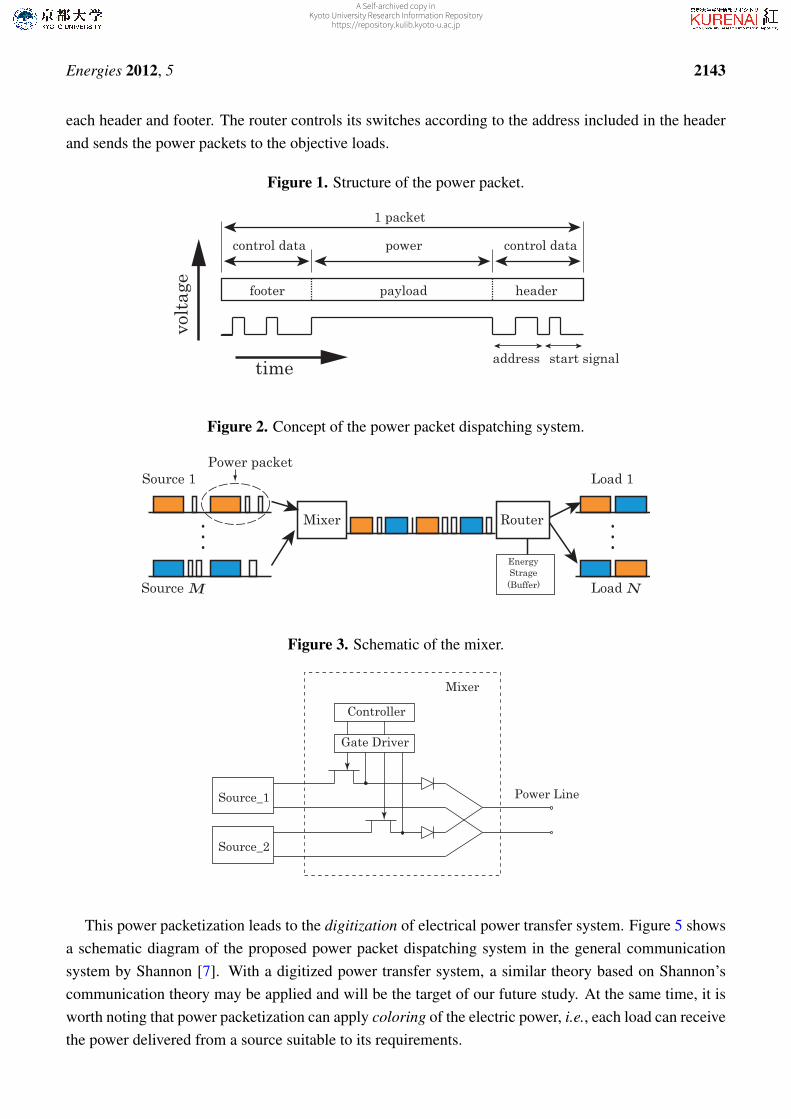
The structure of the power packet is depicted in the time domain in Figure 1 [2]. The amount ofsupplied power per packet is regulated by changing the length of the payload or modulating the payloads.The header and footer are physically attached to the payload as a tag. The tag contains several pieces ofinformation such as the address of the source and the destination of the load. The footer is the mark ofthe end of the packet. The electric power and the information tag are transferred together in a packet inthe same physical layer.
Figure 2 shows a conceptual diagram of the power packet dispatching system. The system consistsof multiple power sources, multiple loads, a mixer, a router, and a distribution line between the mixerand router. Each of these sources and loads is assigned a unique address. Figures 3 and 4 depict thecircuit diagram of the mixer used in the experiment and a schematic diagram of the router shown in [2],respectively. The mixer has already been implemented and tested. The mixer sorts the packets fromvarious sources to prevent overlapping of the payloads by controlling the switches on the lines. Thus,the mixer performs the time-division multiple access (TDMA). The router receives the packets and reads
A Self-archived copy inKyoto University Research Information Repository
https://repository.kulib.kyoto-u.ac.jp
Energies 2012, 5 2143
each header and footer. The router controls its switches according to the address included in the headerand sends the power packets to the objective loads.
Figure 1. Structure of the power packet.
headerpayloadfooter
control data control datapower
start signaladdress
1 packet
time
volt
age
Figure 2. Concept of the power packet dispatching system.
●
●
●
●
●
●
Source 1
Source
Load 1
LoadM N
Power packet
Mixer Router
EnergyStrage
(Buffer)
Figure 3. Schematic of the mixer.
Source_1
Source_2
Gate Driver
Controller
Mixer
Power Line
This power packetization leads to the digitization of electrical power transfer system. Figure 5 showsa schematic diagram of the proposed power packet dispatching system in the general communicationsystem by Shannon [7]. With a digitized power transfer system, a similar theory based on Shannon’scommunication theory may be applied and will be the target of our future study. At the same time, it isworth noting that power packetization can apply coloring of the electric power, i.e., each load can receivethe power delivered from a source suitable to its requirements.
A Self-archived copy inKyoto University Research Information Repository
https://repository.kulib.kyoto-u.ac.jp

Energies 2012, 5 2144
Figure 4. Schematic of the router.
Load_1
Load_2
ControllerIsolator
Power Line
Router
Figure 5. Schematic diagram comparing a general communication system and a powerpacket dispatching system. Communication and power packet dispatching systems areindicated in blue (upper) and red (lower), respectively.
Transmitter
Noise
Destination
Channel
Receiver
Signal
Message
Message
Message+
Load
Information source
Power source
Power
Message+
Power
Signal+
Power
3. Indoor Power Line Channel
Recently, the propagation characteristics of power line channels have been investigated in the contextof power line communication [8–10]. Tsuzuki et al. estimated the transfer function of indoor powerline channels [8]. Figure 6 shows one of the configurations of these channels. The power line is a VVFcable with two wires of ϕ1.6 mm, which is widely used for indoor power lines in Japan. The signal istransmitted and received at points A and D. At points E and F, appliances can be connected. Impedancemismatching causes a signal reflection, which results in a frequency selective fading response in thepower line channel. In [8], the practical mathematical model of the transfer function is developed for theVVF cable by adopting measured parameters.
Here, we consider two configurations for dispatching power packets based on the model obtainedin [8]. One is the branched configuration shown in Figure 6. The other is the branch-less configurationbased on the above model, i.e., a straight VVF cable stretched between points A and D. The transferfunction of the branch-less model can be obtained by adopting the parameters of the above model. Weassume that a power source and a destination load are set at points A and D, respectively. A mixeris set between the source and the power line, and a router is also set between the power line and theload. Ideally, the mixer and the router are assumed to be included in the source and load, respectively.The impedances are matched among the VVF cable, the switches in the mixer and router, the internalresistance of the source, and the destination load. Thus, there is no signal reflection at the junction points
A Self-archived copy inKyoto University Research Information Repository
https://repository.kulib.kyoto-u.ac.jp
Energies 2012, 5 2145
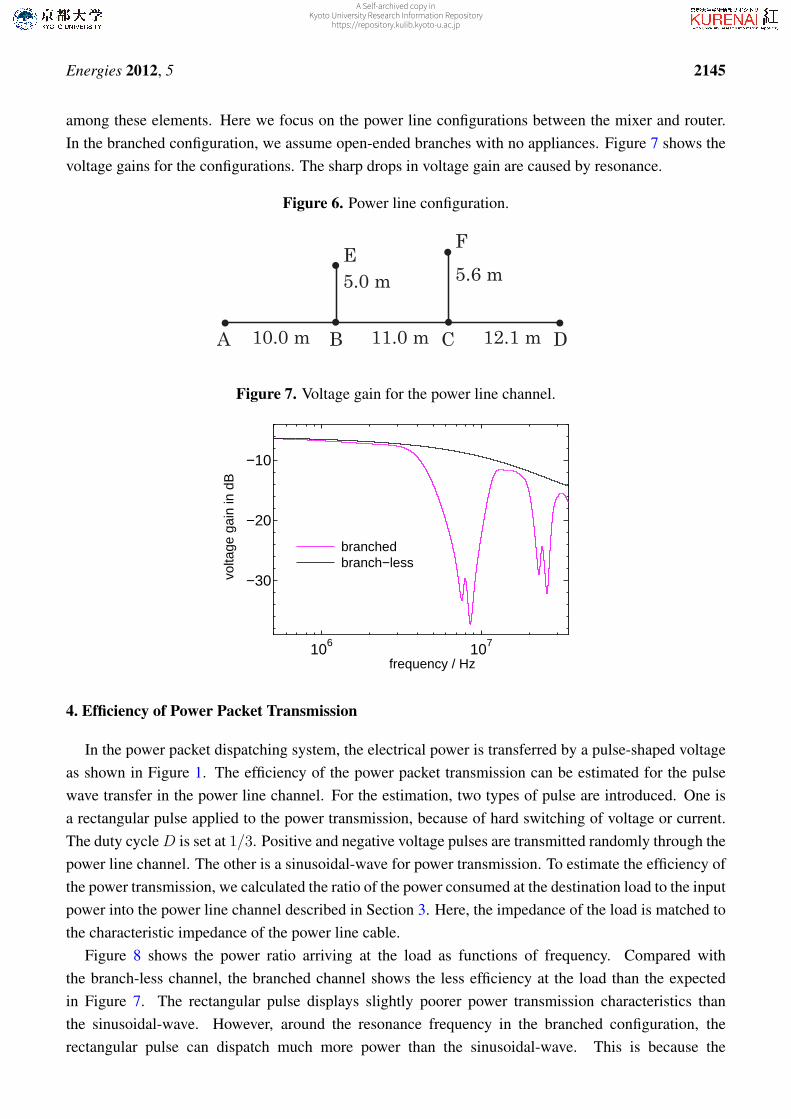
among these elements. Here we focus on the power line configurations between the mixer and router.In the branched configuration, we assume open-ended branches with no appliances. Figure 7 shows thevoltage gains for the configurations. The sharp drops in voltage gain are caused by resonance.
Figure 6. Power line configuration.
A B C D
EF
10.0 m 11.0 m 12.1 m
5.0 m 5.6 m
Figure 7. Voltage gain for the power line channel.
106 107
−30
−20
−10
frequency / Hz
volta
ge g
ain
in d
B
branchedbranch−less
4. Efficiency of Power Packet Transmission
In the power packet dispatching system, the electrical power is transferred by a pulse-shaped voltageas shown in Figure 1. The efficiency of the power packet transmission can be estimated for the pulsewave transfer in the power line channel. For the estimation, two types of pulse are introduced. One isa rectangular pulse applied to the power transmission, because of hard switching of voltage or current.The duty cycle D is set at 1/3. Positive and negative voltage pulses are transmitted randomly through thepower line channel. The other is a sinusoidal-wave for power transmission. To estimate the efficiency ofthe power transmission, we calculated the ratio of the power consumed at the destination load to the inputpower into the power line channel described in Section 3. Here, the impedance of the load is matched tothe characteristic impedance of the power line cable.
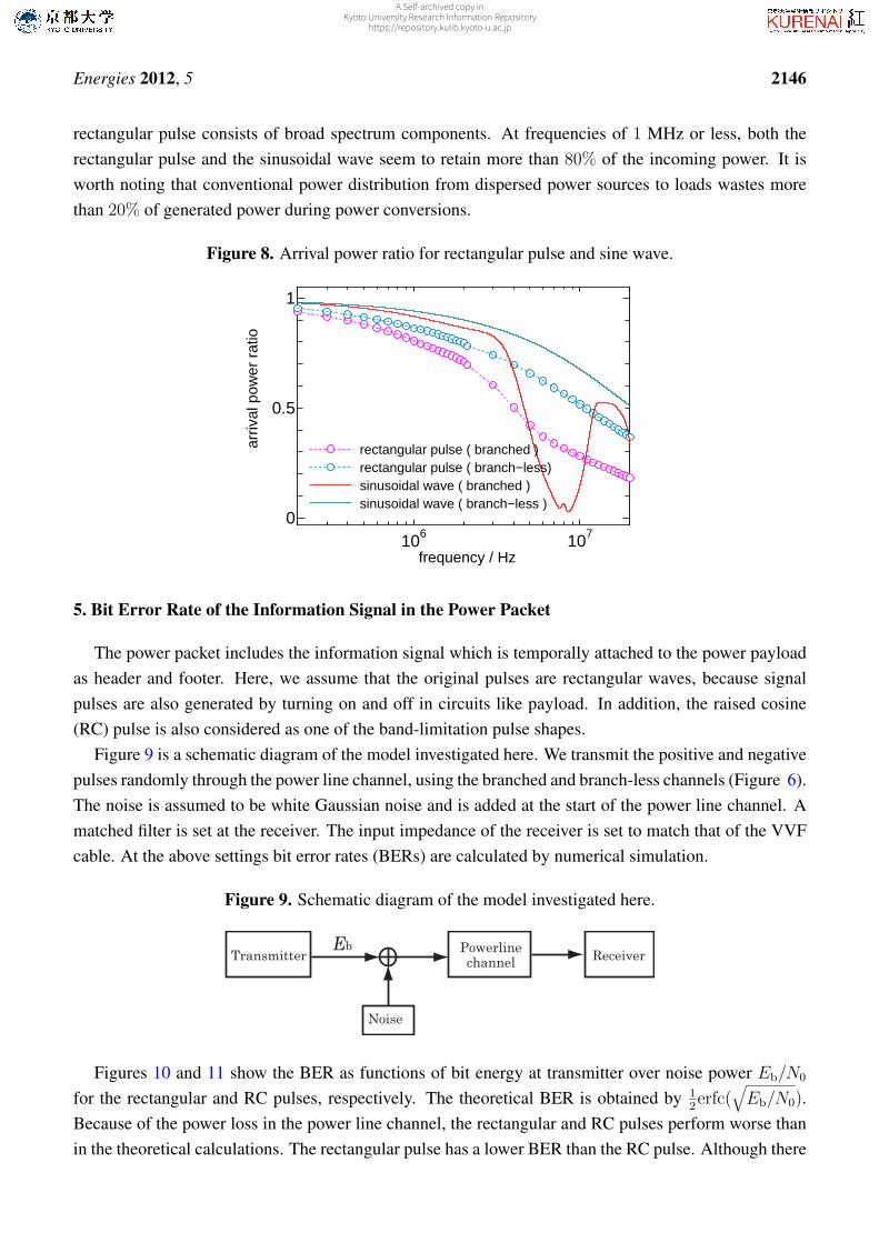
Figure 8 shows the power ratio arriving at the load as functions of frequency. Compared withthe branch-less channel, the branched channel shows the less efficiency at the load than the expectedin Figure 7. The rectangular pulse displays slightly poorer power transmission characteristics thanthe sinusoidal-wave. However, around the resonance frequency in the branched configuration, therectangular pulse can dispatch much more power than the sinusoidal-wave. This is because the
A Self-archived copy inKyoto University Research Information Repository
https://repository.kulib.kyoto-u.ac.jp
Energies 2012, 5 2146
rectangular pulse consists of broad spectrum components. At frequencies of 1 MHz or less, both therectangular pulse and the sinusoidal wave seem to retain more than 80% of the incoming power. It isworth noting that conventional power distribution from dispersed power sources to loads wastes morethan 20% of generated power during power conversions.
Figure 8. Arrival power ratio for rectangular pulse and sine wave.
106 1070
0.5
1
frequency / Hz
arriv
al p
ower
rat
io
rectangular pulse ( branched )rectangular pulse ( branch−less)sinusoidal wave ( branched )sinusoidal wave ( branch−less )
5. Bit Error Rate of the Information Signal in the Power Packet
The power packet includes the information signal which is temporally attached to the power payloadas header and footer. Here, we assume that the original pulses are rectangular waves, because signalpulses are also generated by turning on and off in circuits like payload. In addition, the raised cosine(RC) pulse is also considered as one of the band-limitation pulse shapes.
Figure 9 is a schematic diagram of the model investigated here. We transmit the positive and negativepulses randomly through the power line channel, using the branched and branch-less channels (Figure 6).The noise is assumed to be white Gaussian noise and is added at the start of the power line channel. Amatched filter is set at the receiver. The input impedance of the receiver is set to match that of the VVFcable. At the above settings bit error rates (BERs) are calculated by numerical simulation.
Figure 9. Schematic diagram of the model investigated here.
Powerline
channel
Noise
EbTransmitter Receiver
Figures 10 and 11 show the BER as functions of bit energy at transmitter over noise power Eb/N0
for the rectangular and RC pulses, respectively. The theoretical BER is obtained by 12erfc(
√Eb/N0).
Because of the power loss in the power line channel, the rectangular and RC pulses perform worse thanin the theoretical calculations. The rectangular pulse has a lower BER than the RC pulse. Although there
A Self-archived copy inKyoto University Research Information Repository
https://repository.kulib.kyoto-u.ac.jp

Energies 2012, 5 2147
is no bandwidth limitation for the rectangular pulse, in practice it is necessary to apply band-limitedpulse shaping, similar to that of the RC pulse. In both cases, it is clear that the branch-less channelperforms better than the branched channel. These results are important when designing the signal partof the packet with respect to the number of bits in the header and footer. For example, the required bitenergy can be estimated at the transmitter to obtain the desired BER.
Figure 10. Bit error rate for rectangular pulse.
0 10 20
10−20
10−10
100
Eb / N0 in dB
BE
R
: branch−less: branched: theoretical
blackredblue
500kHz2MHz10MHz
Figure 11. Bit error rate for RC pulse.
0 10 20
10−4
10−2
100
Eb / N0 in dB
BE
R
: branch−less: branched: theoretical
500kHz2MHz10MHz
blackred
blue
6. Discussion and Conclusions
We investigated the transfer property of the power packet for indoor power line channels. Twofundamental power line network configurations—branched and branch-less—were considered. We usedtwo-wire VVF electric cable, which is generally adopted for home power lines in Japan. We assumedmatched impedance among the cables, the internal resistance in the packet transmitter and destinationload. In the branched configuration, no appliance connection is assumed at the ends of branches except
A Self-archived copy inKyoto University Research Information Repository
https://repository.kulib.kyoto-u.ac.jp

Energies 2012, 5 2148
the destination load. We investigated the BER and the ratio between the power at the source and at theload by numerical simulations for the two system configurations.
This power packet system is intended to be implemented in a DC power delivery system. Thepower packet is formed by an on–off switch connected to the DC power sources. Currently, AC powerdistribution systems lose more than 20% power because of power conversion. Our investigation showsthat more than 80% of the source power can be dispatched to the destination load at frequencies up to1 MHz for both the branched and branch-less channels used in this study. In addition, “coloring” androuting can be obtained by using the power packet, enabling the balancing of the power quality betweenthe source and the load. Initially, power distribution is considered inside a small unit such as a home or abuilding with an independent power line from the commercial power system. From the BER evaluation,it is possible to estimate the bit energy at the transmitter to obtain the desired BER. This estimationmakes it possible to estimate the number of bits that can be used as the header and footer. In the powerpacket dispatching system, the mixer and router are set at the connection point of the source, load, andpower line. Here, the mixer and router are assumed to be included in the source and load, respectively. Inpractice, the impedances of the mixer and router are not always matched with the other impedances suchas the internal resistance of the source. The impedance mismatching causes the reflection of voltage orcurrent, and changes the transfer function of the channel. Moreover, the switching generates noise in thechannel. The effects of switching noise and impedance mismatching at the sources, loads, mixers, androuters on the power packet dispatching system will be considered as a future topic of this study.
The concept of power packetization and its routing leads to the digitization of the power transferitself. For this, a more effective digital modulation method will be needed. Depending on the numberof the sources and loads, other channel access methods may be used, apart from TDMA. The flow ofthe power packet contains a wealth of information on people’s private daily consumption habits. Thus,the power packet system requires highly secure structure. The security of the system is a further topicto be discussed in this research. To implement the system, high-voltage and high-frequency powerswitching device are essential to the power packet. In addition, the switching devices should be asenergy efficient as possible. Simultaneously, experimental verification is also important. The generationof power packets has already been verified in experiments in laboratory and in residential houses [2,4].The implementation of SiC power devices depends on the system ratings. It has the benefit of low powerloss for high frequency applications.
The power packets have the potential to achieve efficient power transfer to the objective load. It isconsidered that the power packet routing system can achieve the on-demand home energy networkingrequirements [11]. It is also possible to stop the power supply to idling loads and save wasted electricitybecause of the path selection and bi-directional characteristics attained by the power packet transmission.This power packet transfer system makes it possible to control the flow of electric power in the form ofdiscretization. In this study, we focus on one source and one load connection as a small network unit.In this unit, the packet routing control is not considered. In a practical network system, it would benecessary to consider the routing algorithm and its evaluation, e.g., [11,12]. The expansion of networkis also future topic in our research. We expect to obtain an effective decrease in energy loss and to beable to select power sources without mixing power by using power packetization and its routing.
A Self-archived copy inKyoto University Research Information Repository
https://repository.kulib.kyoto-u.ac.jp

Energies 2012, 5 2149
Acknowledgments
This research is partially supported by the National Institute of Information and CommunicationsTechnology, Japan. We greatly appreciate the fruitful discussion with Yasuo Okabe, Kyoto University.The authors would like to thank the reviewers for their valuable comments.
References
1. Hikihara, T. Power router and packetization project for home electric energy management.Presented at the Santa Barbara Summit on Energy Efficiency; Santa Barbara, CA, USA, 2010.
2. Takuno, T.; Koyama, M.; Hikihara, T. In-home power distribution systems by circuit switchingand power packet dispatching. In Proceedings of the 2010 First IEEE International Conference onSmart Grid Communications, Gaithersburg, MD, USA, 2010; pp. 427–430.
3. Takuno, T.; Kitamori, U.; Takahashi, R.; Hikihara, T. AC Power routing system in home based ondemand and supply utilizing distributed power sources. Energies 2011, 4, 717–726.
4. Takuno, T. High Frequency Switching of SiC Transistors and Its Application to In-Home PowerDistribution. Ph.D. Dissertation, Kyoto University, Kyoto, Japan, 2012.
5. Toyoda, J.; Saitoh, H. Proposal of an Open-Electric-Energy-Network(OEEN) to realize cooperativeoperations of IOU and IPP. In Proceedings of the 1998 International Conference on EnergyManagement and Power Delivery (EMPD ’98), Singapore, 3–5 March 1998; Volume 1,pp. 218–222.
6. Gelenbe, E. Energy packet networks: Adaptive energy management for the cloud. In Proceedingsof the 2nd International Workshop on Cloud Computing Platforms, Bern, Switzerland, 10 April2012; Article No. 1.
7. Shannon, C.E. A mathematical theory of communication. Bell Syst. Tech. J. 1948, 27, 379–423;623–656.
8. Tsuzuki, S.; Takamatsu T.; Nishio, H.; Yamada, Y. An estimation method of the transfer function ofindoor power-line channels for japanese houses. In Proceedings of IEEE International Symposiumon Power-Line Communications and Its Applications (ISPLC2002), Athens, Greece, 27–29 March2002; pp. 55–59.
9. Zimmermann, M.; Dostert, K. A Multipath model for the powerline channel. IEEE Trans.Commun. 2002, 50, 553–559.
10. Galli, S.; Banwell, T. A novel approach to the modeling of the indoor power line channel—Part II:Transfer function and its properties. IEEE Trans. Power Deliv. 2005, 20, 1869–1878.
11. Sakai, K.; Okabe, Y. Quality-aware energy routing toward on-demand home energy networking.In Proceedings of 2011 IEEE Consumer Communications an Network Conference; Las Vegas, NV,USA, 9–12 January 2011; pp. 1041–1044.
12. Gelenbe, E.; Morfopoulou, C. A framework for energy aware routing in packet networks. Comp.J. 2011, 54, 850–859.
c⃝ 2012 by the authors; licensee MDPI, Basel, Switzerland. This article is an open access articledistributed under the terms and conditions of the Creative Commons Attribution license(http://creativecommons.org/licenses/by/3.0/).
A Self-archived copy inKyoto University Research Information Repository
https://repository.kulib.kyoto-u.ac.jp