“tiso-production” ltd servo-operated waist-high turnstile ... · “tiso-production” ltd....
TRANSCRIPT
1
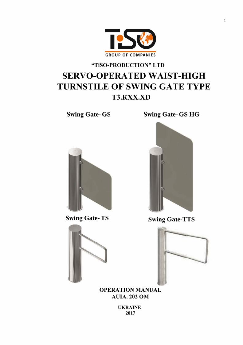
“TiSO-PRODUCTION” LTD
SERVO-OPERATED WAIST-HIGH TURNSTILE OF SWING GATE TYPE
T3.КХХ.XD
Swing Gate- GS Swing Gate- GS HG
Swing Gate- TS Swing Gate-TTS
OPERATION MANUALAUIA. 202 OM
UKRAINE2017

2
CONTENTS
INTRODUCTION.......................................................................................................................................................... 3
1. DESCRIPTION AND OPERATION......................................................................................................................... 5
1.1 General Information and Purpose.................................................................................................................... 5
1.2 Specifications...................................................................................................................................................6
1.1 Configuration and Scope of Delivery.............................................................................................................. 7
1.4 Design and Operation .................................................................................................................................... .8
1.5 Instrumentation, tools and accessories.......................................................................................................... .10
1.6 Marking........................................................................................................................................................ .10
1.7 Packing .......................................................................................................................................................... 11
1.8 Description and operation of controllers as a component of the turnstile...................................................... 12
2. INTENDED USE...................................................................................................................................................... 16
2.1 Operation restrictions..................................................................................................................................... 16
2.2 Layout and installation. ................................................................................................................................ 16
2.3 Preparation for use ........................................................................................................................................ 22
2.4 Contingency actions...................................................................................................................................... 22
3. MAINTENANCE.................................................................................................................................................... 23
3.1 General guidelines........................................................................................................................................ 23
3.2 Safety measures............................................................................................................................................ 23
3.3 Maintenance procedure................................................................................................................................. 23
4. ROUTINE MAINTENANCE..................................................................................................................................24
4.1 General guidelines.........................................................................................................................................24
4.2 Troubleshooting.............................................................................................................................................24
4.3 Postrepair checkout....................................................................................................................................... 25
5. TRANSPORTATION AND STORAGE....... .......................................................................................................... 25
5.1 Turnstile storage............................................................................................................................................ 25
5.2 Turnstile transportation..................................................................................................................................25
6. DISPOSAL.............................................................................................................................................................. .25
7. PACKING CERTIFICATE..................................................................................................................................... 26
8. ACCEPTANCE CERTIFICATE............................................................................................................................ .26
9. MANUFACTURER’S WARRANTY AND TERMS OF WARRANTY MAINTENANCE..................................27Annex А 1: Design, overall, and installation dimensions of the "Swing Gate GS" type turnstile................................29
Annex B: Control panel and connection diagram......................................................................................................... 33
Annex C: Wirung diagram of the swing gate type servo-operated waist-high turnstile............................................. 35
Annex D 1: Wiring diagram of the turnstile connection to access control system (ACS)...........................................36
Annex D 2: Wiring diagram of the turnstile connection to fire alarm system (FAS)..................................................... 37
Annex D 6: Diagram of the turnstile connection to control panel.................................................................................. 41
Annex А 2: Design, overall, and installation dimensions of the "Swing Gate GS HG" type turnstile.........................30
Annex А 3: Design, overall, and installation dimensions of the "Swing Gate TS" type turnstile................................31
Annex А 4: Design, overall, and installation dimensions of the "Swing Gate TTS" type turnstile.............................32
Annex D 3: Wiring diagram of the turnstile connection to fire alarm system (FAS).................................................... 38
Annex D 4: Wiring diagram of the turnstile connection to fire alarm system (FAS).................................................... 39
Annex D 5: Wiring diagram of the turnstile connection to fire alarm system (FAS)..................................................... 40

3
T3.К ХХ.X D
Waist-high turnstile
Swing Gate with P-shape barrier rotation to both sides
Servo-operated,
with P-shape stainless steel barrier
СН K Painted housing
P Polished stainless steel
Servo-operated, with P-shape glass
barrier СС S Brushed stainless steel
Example of reference designation of the servo-operated waist-high turnstile of swing gate type made of brushed stainless steel when the turnstile T3.КСС.PD ТY Y 31.6-32421280-004:2010 is ordered.
INTRODUCTIONThis Operation Manual (hereinafter referred to as OM) covers the servo-operated waist-high turnstile of swing gate type (hereinafter referred to as the "turnstile"). The Operation Manual contains information about design, specifications, installation for proper operation and maintenance of the turnstile.
This Operation Manual is prepared in compliance with the specification requirements ТY Y 31.6-32421280-004:2010.
The turnstile shall be serviced only by the qualified staff having the relevant class of permit to work with electrical facilities with voltage up to 1000V and scrutinizing this Operation Manual, obtaining safety instructions and trained for operation and maintenance of the turnstile. Reliability and durability of the turnstile operation is provided with observation of modes and conditions of transportation, storage, installation and operation. So, fulfillment of all requirements specified in this document is mandatory.
Depending on the purpose and design features of the turnstile, the following pattern of reference designation is accepted:
Due to regular improvement of the product its design can be modified without degradation of the product features and quality not covered by this Operation Manual.

4
WARNINGS TO THE CUSTOMER ON SAFE OPERATION OF THE TURNSTILE
These warnings are designed for ensuring of safety during operation of the turnstile to prevent violation of safety characteristics by improper installation or operation. These warnings are aimed at drawing attention of the customer to safety problems.
GENERAL WARNINGSThe Operation Manual is an integral part of the product and it shall be handed over to the customer. The OM shall be kept for later use and consulted for clarifications if required. If the turnstile is resold, handed over to another owner or transported to another place, make sure that the OM is enclosed to the turnstile to be used by new owner and/or maintenance staff during installation and/or operation.
Safety measures and requirements specified in this in this OM must be observed:– the turnstile must be connected to ground loop prior to operation;– the turnstile should be connected to AC network with parameters specified in paragraph
1.2 "Specifications";– inspection, adjustment and repair should be performed only after the turnstile is
deenergized.
After purchasing of the turnstile it should be unpacked and its integrity should be checked. In case of doubt in integrity of the turnstile it should not be used and the customer should refer to the supplier or to the manufacturer. Packing accessories (wooden pallet, nails, clips, polyethylene bags, cardboard etc.) as potential sources of hazard must be removed to unacceptable place prior to proper use of the turnstile. As electric shock protection device the turnstile is related to 01 protection class according to GOST (State Standard) 12.2.007.0-75 and is not intended for operation in explosive and fire-hazardous areas by the "Rules for design of electrical installations".
Using of the turnstile for unintended purpose, improper installation, nonobservance of conditions of transportation, storage, installation and operation, specified by this OM, may result in damage to people, animals or property for which the manufacturer is not responsible.

5
Table 1
Designation of modification
Model AUIA.202
Access way
width
Dimensions, mm Max.weight, kg Height Length Width
Т3.KСC.SD
Т3.KСC.PD
Т3.KСC.KD
«Gate-GS» 650
1000 225 836
80 900 1071
«Gate-GS-HG» 650
1540 225 836
90 900 1071
Т3.KСН.SD
Т3.KСН.PD
Т3.KСН.KD
«Gate-TS» 650
1000 225 837
60 900 1087
«Gate-TTS» 550-900 1000 225 765-1115 70
Table 2
Continued Table 2
1. DESCRIPTION AND OPERATION
1.1 General Information and Purpose
1.1.1 Name of product: Swing gate type waist-high turnstile T3.K________.D______
MC4
_______________ 20_____
"TiSO-PRODUCTION" LTD., City of Kiev
Designation: Climatic modification: Date of manufacture: Manufacturer: Serial Number: _________________________________
1.1.2 Purpose:
The turnstile is designed for pedestrian movement control at access points of industrial enterprises, banks, stadiums, administrative facilities etc. controlled by access control system (from proximity card readers) or manually (from manual control panel).
The turnstile traffic flow capacity without personal identification is at least 20 persons per minute in one direction.
1.1.3 The turnstile dimensions and weight correspond to the values specified in Table 1.
1.1.4 The operation condition parameters according to GOST 15150-69 and GOST 12997-84 are specified in Table 3.
Operation conditions
For climatic modification Parameter value
Ambient air temperature +1 to +40°С
Relative air humidity 80% at +20ºС

6
1.1.5 Reliability indices:
1.2 Specifications
The key parameters of the turnstile are specified in Table 3. Table 3
Parameter description Unit measure Parameter value
Minimum traffic flow capacity in free access mode man/min. 60
Minimum traffic flow capacity in single access mode man/min. 20
Maximum access way width- narrow P-shape barrier - wide P-shape barrier - controlled P-shape barrier
mm 675*
925*
925**
Power supply voltage:
MC4Ambient air allowable pressure 84 to 106,7kPa
Transportation temperature range - 40°С to + 50°С
Storage temperature range + 5 to + 40°С
Group of mechanical application
MC4
L3
Altitude above sea level up to 2000m
Environment
Explosion-proof, does not contain current-conducting dust, aggressive gases and vapours in concentration destroying isolation and metals, disturbing normal operation of the equipment installed in turnstiles
Installation siteIn enclosed spaces in the absence of direct impact of precipitations and solar radiation
Operating positionVertical, deviation from vertical position no more than 1º to any side is allowed
mean time to repair (without delivery time of spare parts, tools and accessories) – at most 6 hours;– mean time to failure – at least 1 500 000 accesses;– mean service life between overhauls – at least 10 years.

7
Continued Table 3
1.3 Configuration and Scope of Delivery
1.3.1 The swing gate type waist-high turnstile design includes the following key devices and components:
– body;
– P-shape barrier;– actuator;– control unit;
Design, overall and installation dimensions of the turnstile are shown in Annex A.
1.3.1.2 The turnstile modification is based on the P-shape barrier material: 1) stainless steel P-shape barrier (reference designation T3.КCН.XD);2) glass P-shape barrier (reference designation T3.КСС.XD).
1.3.1.3 The turnstile modifications are manufactured from:
– brushed stainless steel (reference designation T3.КXХ.SD).
– polished stainless steel (reference designation T3.КXХ.РD).
– carbon steel subject to painting (reference designation T3.КXХ.КD);
1.3.2 Scope of Delivery
The turnstile is delivered by one package, dimensions of which are 353х1060х976 mm.
Scope of delivery is specified in Table 4. Table 4
Product description
Product designation /parameters
Quantity,piece
Note
Swing gate type servo-operated waist-high turnstile Т3.К_______._____D 1 –
Accessories
Control panel AUIA.111.22.00.00 1 –
Mounting kit Redibolt 92116A3-N
(16×130 М12) 3
Anchor with jacket and screw
Operation Manual AUIA.202 OM 1 –
Packing – 1 –
– AC power supply (primary) V
Hz
100 240
~ 50/60
– DC power supply (secondary) W 12
Maximum power consumption WА 55
Index of protection according to GOST ГОСТ 14254-96 - IP41
The turnstile also includes control panel.

8
1.3.3 Design, overall and installation dimensions of the turnstile are shown in Annex А.
1.3.4 The turnstile material of manufacture is carbon steel subject to painting, brushed stainless steel or polished stainless steel.
Fig. 1 – General appearance of the turnstile
1.4.2 Turnstile design
1.4.2.1 The swing gate consists of cup 2 with fixed base (See Figures 1, 2).
1) Body 6 with P-shape barrier 1 from glass or tube is installed on cup 2 from the top.
Body is connected with control unit and servomotor by means of screw with washers, providing rotation of P-shape barrier to both sides at the angle of 90°.
1.4.2.2 Lid 7 is installed on body from the top and is fixed with a screw with washers. Plug 4 is fixed to the lid at the top by means of magnet (included in the scope of delivery) after the turnstile installation, connection and assembly.
1.4 Design and operation
1.4.1 General appearance of the turnstile
Body Lid Glass holder
Actuator
Control unit P-shape barrier*
Cup
* P-shape barrier options
P-shape barrier from glass
P-shape barrier from glass
P-shape barrier from stainless steel
Extendible P-shape barrier from stainless steel

9
1.4.2.3 Control unit and servo motor 3 are located at the bottom of the turnstile body. P-shape barrier is automatically brought to initial position by means of servomotor after each turnstile access.
1.4.2.4 Control unit 3 is a metal box installed on cup 2. Power supply unit and card, on which controllers with electronic components and connectors for peripheral connections are fixed inside control unit.
Control unit is designed for the turnstile energization and latching control.
1.4.2.5 Control panel is made as small desktop device in plastic case and is designed for setting and indication of operating modes when the turnstile is operated manually. Control panel and its connection diagram are shown in Annex A.
Fig. 2 – Design of swing gate type turnstile
1 – P-shape barrier (glass or tube);
2 – cup;
3 – control unit and actuator; 4 – plug;
5 – screw М12 with washers;
6 – body;
7 – lid;
8 – screw М16;
9 – spring washer; 10 – flat washer; 11 – anchor М12;

10
1.4.3 Principle of operation
1.4.3.1 Turnstile operating modes:
1) to be opened in the direction “A” or “B”;
2) free access in the direction “A” or “B”.
Switching of the turnstile operating modes is performed either by control panel or as part of automated access control system (ACS) (by means of cards, badges etc.).
1.4.3.2 In the initial state, when the turnstile is energized, P-shape barrier is locked from rotation in both directions by actuator. After access permission command in one of directions is received:
– P-shape barrier is unlocked;
– servomotor rotates P-shape barrier to the angle of 90° in the appropriate direction;
– after access permission command is cancelled, servomotor brings P-shape barrier back to initial position and it is locked from rotation in both directions
More detailed description of the turnstile operating modes is given in section 1.8 "Description and operation of controller as a component of the turnstile”. 1.4.3.3 12V DC power voltage is provided by power supply unit.
1.4.3.4 The turnstile wiring diagram is shown in Annex C.
1.5 Instrumentation, tools and accessories Dedicated tools are not required for installation of the turnstile (multi-purpose measurement instrumentation and installation tools are sufficient (Fig. 3)).
1.6 Marking
1.6.1 Marking of the turnstiles to be delivered within Ukraine is in Ukrainian language and for export delivery in English.Each turnstile is equipped with identification plate (Fig.4) containing the following data:
name of manufacturer and trade mark;– reference designation of turnstile modification;– index of protection;– serial number;– value of voltage, type of current, frequency
and current consumption;– weight, kg;– date of manufacture;– inscription “MADE IN UKRAINE”.
Identification plate is placed inside the turnstile’s post.
Figure 4 - Identification plate

11
1.6.2 Marking of transportation packing contains as follows:1) Information inscriptions:
turnstile modification reference designation;– dimensions of cargo package in centimeters;– gross weight in kg;– net weight in kg;– volume of package in cubic meters;
2) Handling marks:– "Fragile. Handle with Care";– "Keep dry";– "Centre of gravity";– "Top".
1.6.3 Shipping and operational documentation is packed in a bag from polyethylene film. Marking is applied on insert from cardboard or paper.
1.7 Packing
1.7.1 The turnstile is delivered ready-to-install by components. Types of packing:
– consumer packaging (corrugated cardboard box);– transportation packaging (cases from wood-fiber board or crates).
The turnstile is fixed from displacement in the middle of transportation package with blocking lumbers. Cushion pads are placed between turnstile and lumbers.
1.7.2 Shipping documentation sealed in a bag from polyethylene film is enclosed to the turnstile packing.

12
1.8 DESCRIPTION AND OPERATION OF CONTROLERS AS A COMPONENT OF THE TURNSTILE1.8.1 Purpose of the turnstile controller РСВ.201.01.00.00
The controller is designed for acquisition of commands from external control devices (control panel, access control system etc.) and generation of control signals for swing gate motorized mechanism. 1.8.2 The controller is assembled on the (85 х 70mm) board, on which electronic components and connectors for external connections are mounted.
Table 5
Parameter description Parameter value
Number of inputs 2
Number of outputs 4
Type of input logical Type of output GRN1, RED1, GRN2, RED2 open collector Logical «1» voltage (3,7 5) V
Logical «0» voltage (0 1,7) V
Peak voltage applied to inputs «IN1»÷« IN8» 15 V
Peak voltage switched by outputs «GRN1», «RED1», «GRN2»,
«RED2» 30 V
Peak current switched by outputs «GRN1», «RED1», «GRN2»,
«RED2» 2 А
Peak voltage switched by outputs «-MG1», «-MG2» 50 V
Peak current switched by outputs «-MG1», «-MG2» 5 A
Peak voltage switched by outputs «MOT1», «MOT2» 27 V
Peak current switched by outputs «MOT1», «MOT2» ≤ 4 А
Controller supply voltage (10 27)
V Consumption current when outputs «MOT1» and «МОТ2» are OFF ≤0,15 А
Climatic modification and location category according to GOST 15150-69 MC4
Controller appearance is shown in Figure 2.
13 LEDs are installed on controller board. Their purpose is as follows: • 8 LEDs indicate condition of inputs “IN1» «IN8”. • «POWER» LED indicates availability of supply voltage 5V. • 4 LEDs indicate condition of outputs for connection of motor.24 terminals are installed on board: 2 of them are designed for external connections, the rest are designed for connection to the turnstile units or are standby.
1.8.3 Technical features The controller technical features are shown in Table 5.

13
1.8.4 Description of operation
The controller operates according to the program entered into memory of microprocessor. swing The swing gate mechanism is controlled based on commands coming from external devices (control panel, access control system etc.) and position of rotor based on the logic downloaded into program. Control commands are generated to controller via logical inputs «IN1», «IN2» and «IN3», «IN4» by means of closing them on «GND». Inputs «IN1» and «IN3» are designed for opening of the turnstile in the direction “A” and Inputs «IN2» and «IN4» are designed for opening of the turnstile in the direction “B”. The difference is that 4 sec. closing delay is counted via inputs «IN3» and «IN4». That is in case of short time short-circuit of «IN3» or «IN4» on «GND», the turnstile will open completely and only after a lapse of time it will start closing. There is no such delay via inputs «IN1» and «IN2», and the turnstile will start closing at once from the moment of disappearance of input signal, even if the turnstile is not fully opened. Normally opened contacts of buttons, relay contacts or outputs of open collector type can be used for generation of control commands. That is, in order to generate the command “TO BE OPENED IN THE DIRECTION “A” it is necessary to connect input “IN1» (X1/1) or «IN3» (X1/3) to one of terminals "GND" (X1/9 X1/11)¸ X1/11), accordingly for generation of command “TO BE OPENED IN THE DIRECTION “B” it is necessary to connect input «IN2» (X1/2) or «IN4» (X1/4) to terminal "GND". After obtaining opening command the controller deenergizes winding of solenoid, fixing rotor, connected to output “-MG2” (X2/7). It results in that rotor will be unlock and can be freely rotated in any direction. After that controller feeds current to motor winding via outputs “MOT1” and “MOT2” (X2/9 and X2/10). It results in that rotor starts to rotate opening the access. During rotation of rotor controller reads actual angle of rotation from position sensor rigidly connected to the swing gate rotor. Sensor signals come to inputs “IN5”, “IN6”, “IN8” (X1/5, X1/6, X1/8). Rotation speed signal from the relevant sensor come to the controller input «IN7» (X1/7). Besides motor current is constantly measured and is limited, if necessary. After rotor reaches the definite angle, the controller switches motor to braking mode to prevent impact of rotor about rotation limiter. As soon as rotor rests against limiter, controller feeds little current to motor to hold rotor in open position. Now access opening procedure is finished. In this state the swing gate will remain until the relevant “TO BE OPENED …” command is active. The controller appearance is shown in Figure 4.Closing procedure begins after connection of the relevant input “IN1” or “IN2” with “GND” is open and upon expiration of 4 sec. after connection of input “IN3” or “IN4” with “GND” is open. In order to close the turnstile the controller actuates motor, having changed current polarity via it, that leads to rotation of rotor in opposite direction. In this case angle of rotor rotation and motor speed are controlled. When rotor approaches to fixation point in closed position, the controller reduces revolutions of motor. Then when rotor reached initial position, it feeds current to the solenoid, which fixes rotor, via input «-MG2» (X2/7). It results in complete stopping and locking of rotor in initial position. Now access closing procedure is completed.

14
Fig. 4 – Appearance, overall and connection dimensions of controller РСВ.201.01.00.00
The controller’s contacts designed for connection of peripherals are specofied in Table 6.
Table 6
Connector /Contact No Designation Direction Purpose Signal parameters and
description
1 2 3 4 5
X1/1 IN1 ENTRY Command “ TO BE OPENED IN THE DIRECTION А”
X1/2 IN2 ENTRY Command “ TO BE OPENED IN THE DIRECTION B”
X1/3 IN3 ENTRY Command “ TO BE OPENED IN THE DIRECTION А” (with 4 sec. closing delay)
X1/4 IN4 ENTRY Command “ TO BE OPENED IN THE DIRECTION B” (with 4 sec. closing delay)
1)
(0 1,7) V;
2) logical «1»
(3,7 5) V;
3) active level of signal– logical «0»;
4) voltage on openinput ≤ 5 V
logical «0»

15
Continued Table 6
1 2 3 4 5
X1/5 IN5 ENTRY To be connected to position sensor X1/6 IN6 ENTRY
X1/7 IN7 ENTRY To be connected to speed sensor
X1/8 IN8 ENTRY To be connected to position sensor
X1/9 GND «-» power supply (common wire) X1/10 GND
X1/11 GND
X1/12 +5 В EXIT Not applicable
X2/1 GRN1 EXIT To be connected to green LED display of the direction «А»
X2/2 RED1 EXIT To be connected to red LED display of the direction «А»
X2/3 GRN2 EXIT To be connected to green LED display of the direction «B»
X2/4 RED2 EXIT To be connected to red LED display of the direction «B»
X2/5 -MG1 EXIT Connection of solenoid forcing winding
1) type of output – open collector; 2) peak voltage on privacy key – 50 V; 3) peak current of public key – 5 A
X2/6 +MG1 EXIT Connection of solenoid forcing winding (cathode of protective diode)
X2/7 -MG2 EXIT Not applicable
X2/8 +MG2 EXIT
X2/9 MOT1 EXIT
Motor connection 1) voltage(10 ÷ 27) V;
2) current ≤ 4 АX2/10 MOT2 EXIT
X2/11 GND
X2/12 +24 V ENTRY «+» power supply (controller energization)
1) voltage(10 ÷ 27) В;
2) current ≤ 4 А
1) type of output – open collector; 2) peak voltage on privacy key – 50 V; 3) peak current of public key – 5 A
«-» power supply (common wire)

16
2 INTENDED USE 2.1 Operation restrictions
2.1.1 The turnstile must be used in the environment specified in p. 1.1.5 of this document subject to the specifications listed in section 1.2.
IT IS FORBIDDEN:
1) TO MISUSE THE TURNSTILE (See section 1 "DESCRIPTION AND
2) TO USE THE TURNSTILE UNEARTHED;
3) TO USE HEATING PIPES AND RADIATIONS AS WELL AS PIPES OF
4) TO REPAIR AND ADJUST WITHOUT DEENERGIZATION;5) TO RELOCATE THE OBJECTS EXCEEDING THE PASSAGEWAY
WIDTH THROUGH THE TURNSTILE ACCESS AREA;6) TO JERK AND IMPACT BARRIER RODS, LED DISPLAY OR OTHER
PARTS THE PRODUCT, WHICH MAY CAUSE THEIR MECHANICALDAMAGE;
7) EXERT FORCE ON LEAVES MORE THAN 400 Н (40 KG) IN“ACCESS LOCKING” MODE
2.1.2 It is forbidden to use the turnstile:– at the presence of mechanical rattle in movable parts of the turnstile;– when metalwork of the turnstile and its components and accessories are mechanically
damaged.
2.1.3 List of special operation conditions Mean time of the turnstile access (in single access mode) equals to 3 sec.
The turnstile’s mechanism allows emergency access by means of antipanic device.
The force applied by accessor to barrier rod should not exceed 60Н.
Escape door, portal or pedestrian gate can be installed near the turnstile to increase
the turnstile traffic flow capacity in case of emergency.
IMPORTANT: MANUFACTURER WARNS OF THE NECESSITY TO KEEP SEALS OF THE MANUFACTURER ON THE TURNSTILE’S COMPONENTS!
2.2 Layout and installation
2.2.1 The turnstile and components of scope of supply to be delivered to installation site in factory packing. The turnstile to be unpacked only on installation site.
OPERATION");
CENTRAL WATER SUPPLY FOR EARTHING

17
2.2.2 Preparation of the turnstile for installation (dismounting) and commissioning to be performed according to this OM with mandatory observation of safety measures specified in p. 2.1 and general electrical safety code.
2.2.3 Safety Measures:
Installation to be performed only by the persons briefed on safety and studied thismanual;
Only serviceable tools to be used during installation of the turnstile;
Connection of all cables to be performed only when power supply is OFF;
Cables to be laid in compliance with electric code;
The turnstile to be installed by at least 2 installers.
2.2.4 Tools and accessories to be used (Fig.8):
puncher; concrete drills (according to diameter of anchors included in the turnstile scope of delivery; extension cord;
kit of end and pin wrenches;
kit of hexagons;
kit of screwdrivers;
hammer; multimeter (tester); measuring tape ; marker; pliers, side cutters;
builder's level.
Figure 5 - Tools and accessories for layout and installation
WARNING: The turnstile damages occurred during transportation are not covered by themanufacturer's warranty liabilities.

18
2.2.5 Turnstile layout options
Option А Option B
Figure 6 – Turnstile layout options
3) Make sure that the turnstile installation area is ready as follows: The installation site surface to be flat, hard and without defects (potholes, unevenness
etc.) and upright installation plus minus 1° to be provided; Thickness of concrete blinding coat under site to be at least 150 mm.
WARNING: The turnstile is fixed by means of Redibolt (with jacket and screw) included in the scope of delivery.
5) The turnstile fixation holes to be marked on the area surface according to Figure 10. The turnstile itself can be used as a template.
6) The relevant holes to be drilled on the surface according to the marking due to diameter of anchors (12×120М10) for the turnstile fixation.
7) Anchor jackets to be inserted into the prepared holes.
WARNING:The turnstile installation and fixation to be performed only after all electric cables are pulled.
2.2.6 Installation procedureThe turnstile installation procedure is as follows:
1) The package integrity to be checked prior to unpacking. If package is damaged, thendamages to be fixed (picture to be taken, damage report to be made).
2) The turnstiled to be unpacked and inspected for defects and damages as well as completeness to be checked according to the turnstile data sheet;
WARNING:
When the turnstile damages are detected or in case of shortage of delivery, installation work to be stopped and the turnstile supplier to be referred to.

19
Figure 7 – Swing gate type turnstile installation marking
Fig. 8 – Swing gate type turnstile cable entry in corrugated or metal pipes
8) The following cables to be run to the turnstile installation site:
Power supply cable 220 V ~; Control panel connection cable; Access Control System connection cables, if available; Cables between pedestrian gates (Figure 12)
Cables to be run in corrugated or metal pipes (See Figure 8).

20
1
2
3
4
5
9) The length of cable free ends to be at least1 m to provide their entry, termination andconnection to the relevant terminals in theturnstile post.
10) The cable outlet point to be aligned withthe hole on the turnstile mounting plate.
11) The turnstile to be installed upright at theprepared location (Figure 9).- Cables to be pulled through availableaccess holes in the turnstile post bottomend part by relining the turnstile.- Fixation holes at the turnstile bottomplate to be aligned with prepared surfaceholes.- The turnstile to be fixed by means ofanchors included in the scope of delivery.
- Swing gate body to be joined with P-shape barrier:а) The swing gate with glass P-shape barrier to be attached by means of two screws and washers to glassholder,which is welded to the swing gatebody.b) The swing gate with stainless steelP-shape barrier to be attached by screwsМ16 to be tightened from inside.- The swing gate with P-shape barrier to be installed on cup.
* The turnstile to be connected prior toinstallation (See p.12 of section 2.2.6)
- Lid to be installed on body of assembled swing gate.
- Fixing screw with washers to be tighten (not up to the stop) with a force not more than 2N × m.The turnstile performance to be checked.
* In case of difficul moving (turning) of theswing gate, the screw to be a littleloosened. Plug to be put on the turnstileupper lid (with magnet down) uponcompletion of adjustment.
Fig. 9 – Installation of swing gate type turnstile

21
а) to terminal 220 V
b) Power supply ON/OFFbutton
Figure 10 – Connection of power supply cable
Figure 11 – Connection of control panel communication cable to terminals
WARNING:
During the turnstile installation it is necessary to take into account that P-shape barrier to be located at a distance not more than (50 ÷ 100 mm) from access way creator (any surface perpendicular to P-shape barrier: enclosure module, wall etc.).
12) Turnstile connection:
a) Power supply cable ~220 V to be connected(Fig. 10):- Phase L to be connected to the circuit breaker;- Neutral (N) to be connected to terminal ~220V(N);
- Earth (РЕ) to be connected to earthing terminal (РЕ).
b) Control panel cable to be connected to terminals(Fig. 11):1 - LED «Closed A»2 - LED «Opened A»3 - «Open A»4 - +12 V5 - GND - common wire of control panel;6 - «Open B»
7 - LED «Open B»
8 - LED «Closed B»
Connection diagram of the turnstile and control panel is shown Annex D6.

22
2.3 Preparation for use
Table 7
Operation modeControl panel
Required inspections Toggle-switch position
utton position
1 Initial state(swing gate is in closed position) OFF Released
Make sure that rotor is locked from rotation in any direction
2 To be opened in the relevant direction OFF
Button of the relevant direction
is pushed
Make sure that rotor is turned in the desired direction to the angle of about 90°, and after the button is released it should return to the initial state
3 Free access in the relevant direction
Toggle-switch of the relevant
direction is ON
Released
Make sure that rotor is turned in the desired direction to the angle of about 90°, and after the toggle-switch button is OFF it should return to the initial state
2.3.2.2 After the turnstile is inspected it is ready for long-term operation.
2.4 Contingency actions
For emergency evacuation of people (in case of fire, acts of God etc.) and providing free access the turnstile to be unlocked from control panel by sending the relevant command.
2.3.1 Commission guidelinesPrior to the turnstile energization:
1) make sure of proper connection and good condition of all connecting cables;2) clear the turnstile’s P-shape barrier turning area from foreign particles.
otation of P-shape barrier is locked when mains cable of power supply unit is connected to the network. The turnstile is put in initial state access is blocked by P-shape barrier.
2.3.2 Required inspections2.3.2.1 hen the turnstile is commissioned it is necessary to perform the inspections specified in Table . During inspections the wiring diagram according to Annex C and the control panel according to Annex to be used.

23
3 MAINTENANCE
3.1 General guidelines
3.1.1 Commissioning and subsequent maintenance of the turnstile to be performed only by the staff to be in charge of the turnstile.
3.1.2 The turnstile to be serviced only by the staff having the relevant electrical safety qualification level according to the national requirements.
3.1.3 The turnstile to be installed and operated only by the qualified safety briefed staff having the relevant class of permit to work with electrical facilities with voltage up to 1000V, awaring of this OM, the turnstile design and principle of operation.
3.2 Safety Measures
3.2.1 During maintenance of the turnstile the relevant safety measures according to p. 2.1 to be observed.
FUSES, IT IS FORBIDDEN: TO USE DEFECTIVE APPLIANCES, TOOLS, INSTRUMENTATION THE SERVICE LIFE OF WHICH EXPIRED.
3.2.2 When instrumentations are prepared for operation it is necessary to strictly comply with the safety requirements specified in instrumentation instruction manuals.
3.3 Maintenance procedure
3.3.1 The turnstile maintenance includes preventive measures which are taken according to the established frequency to maintain the turnstile in operational condition, decreasing of component wearing and prevention of faults and malfunctions.
3.3.2 Daily and periodic maintenance of the turnstile are recommended. Normally the daily maintenance is carried out before the beginning of operation or during operational timeout and includes visual inspection of the turnstile's housing and, if required, troubleshooting of mechanical damages, surface corrosion and contamination.
IT IS FORBIDDEN:TO USE ABRASIVE AND CHEMICALLY ACTIVE SUBSTANCES DURING CLEANING OF CONTAMINATED EXTERNAL SURFACES OF THE TURNSTILE.
The recommended stainless steel detergents are given in Table 8.

24
Table 8
Table 9
Symptom Possible cause Remedy
1 Turnstile is not locked in initial position and don’t respond to commands and in this case indication on control panel is absent
Absense of 220V supply voltage
Availability of 220V on the turnstile relevant terminals to be checked and in case of absence the cause to be removed
Power supply unit is out of order Service center to be referred to
2 Control panel does not open turnstile in one or both directions or indication on
Break of circuit between control panel and turnstile controller
Fault to be found and remedied
Detergent description Manufacturer Country of origin
Stainless steel cleaning spray f Polich 3М Group of European companies
Cleaning fluid WellDone Well Done Hungary
Cleaning solution SANO MULTI METAL SANO Israel Foam Dr.BECKMANN Dr.Beckmann Germany Cleaning solution Reinex Edelstahlreiniger Reinex Germany
Stainless steel cleaner Onish United Kingdom
3.3.3 Periodic maintenance is performed at least twice a year and includes as follows: – visual inspection of the turnstile's body, control mechanism and other components for absence of corrosion, warps and other mechanical defects and pollutions;– visual inspection of condition of connecting and mains cables as well as earthing;– verification of the turnstile's performance during manual control in the modes specified in Table 7;– check of security of the turnstile's screw tightening;– lubrication with lubricant ОКB-122-7 according to GOST 18179-90 or Litol 24 (rubbing levers, wheel and pinion teeth of the turnstile actuator (monthly).
4 ROUTINE MAINTENANCE
4.1 General guidelines
Minor malfunctions of the turnstile are listed in Table 9 and are remedied by the customer. More complicated malfunctions are remedied by the manufacturer’s representative.
IMPORTANT: INSPECTION, CLEANING, REPAIR OF THE TURNSTILE COMPONENTS TO BE PERFORMED ONLY AFTER THE TURNSTILE DEENERGIZATION !
4.2 Possible malfunctions
Possible malfunctions of the turnstile and their remedies are listed in Table 9.

25
control panel is violated Controller is out of order Service center to be referred to
Control panel is out of order Service center to be referred to
4.3 Postrepair checkout
The turnstile performance is checked after repair according to paragraph 2.3.2 of this OM.
5 TRANSPORTATION AND STORAGE
5.1 Turnstile storage
It is forbidden to subject the turnstile to jerks and impacts during storage. Transportation trolleys to be used for handling of the turnstile. In storage facilities there should not be aggressive gases and vapours causing metal corrosion.
Air temperature during storage should not be below +50 С and above +400 С and relative air humidity should not be more than 80% at the temperature 20° С.
5.2 Turnstile transportation
The ready-to-install turnstile to be transported according to the transportation regulations related to the relevant mode of transport, such as: – in railway or special containers;
– in closed vehicles;
– waterborne (in ship’s hold) .
Transportation on open platforms is allowed. In this case the packed turnstile to be covered with canvas. Air temperature during transportation should not be below -40°С and above +50°С. After transportation or storage of the turnstile at negative temperatures or increased humidity the turnstile to be kept indoor with normal climatic conditions without original packing within 12 hours before commissioning:1) ambient temperature: + 15°С to +35°С;2) relative humidity: 45% to 80 %;3) atmospheric pressure: 84,0 to 106,7kPa (630-800 mm Hg).
6 DISPOSAL
The turnstile design does not contain materials environmentally hostile and hazardous to health and special measures are not required for its disposal.

26
8. ACCEPTANCE CERTIFICATE
7. PACKING CERTIFICATE
Servo-operated waist-high turnstile Т3. . No. ___________ __
Name of Product Trademark Serial Number
has been packed by "TiSO -PRODUCTION" LTD. _
Name or code of the manufacturer
__________________________________
according to the requirements specified by the applicable technical documentation.
__________________________ ____________________Position Personal Signature Printed Name
__________________________
Year, Month, Date
. No.Servo-operated waist-high turnstile Т3. _________________
Name of Product Trademark Serial Number
has been manufactured and accepted according to the mandatory requirements of the appropriate standards, applicable technical documentation and classified as fit for use.
Head of Quality Control Department
L.S. ______________________________________ ___________________ Personal Signature Printed Name
____________________
Year, Month, Date

27
9 MANUFACTURER'S WARRANTY AND TERMS OF WARRANTY MEAINTENANCE
9.1. The manufacturer guarantees good state and declared quality of the turnstile if conditions of transportation, storage, installation and operation are observed by the consumer.
9.2. The warranty period of the turnstile from the date of sale is:
12 months;
24 months;
36 months,
unless otherwise specified by mutual agreement.9.3 During warranty period the Manufacturer undertakes to perform repair or replacement within 10 days (at the discretion of Manufacturer) of the failed turnstile or its parts having proven factory defects (not due to nonobservance of storage, transportation, installation and operation conditions specified by this OM) preventing further use of the turnstile.
The Manufacturer does not bear responsibility and warranty liabilities for consequences (damage) due to nonobservance of the conditions specified by this OM.
9.4 Warranty liabilities of the Manufacturer are valid only if sections 7, 8, 9 of this OM and warranty coupon are completed as well as the relevant signatures and seals are available. The turnstile is repaired only by the authorized service center of the manufacturer with use of exclusively original spare parts. Warranty liabilities don’t include free-of-charge arrival of technical staff to the Customer for repair.
9.5 The Manufacturer does not bear responsibility and warranty liabilities in case of unintended use of the turnstile (p.2.1.2).
9.6 The relationships between the Manufacturer and the Customer under warranty liabilities are regulated by the applicable law of Ukraine, concluded purchase contracts and manufacturer's warranty according to instruction manuals.
Manufacturer:"TiSO-PRODUCTION" LTD72 Yamskaya str., 03680, Kiev, Ukraine Tel.: +38 (044) 461-79-69 Tel../Fax: +38 (044) 586-46-47E-mail: [email protected], [email protected] www.tiso-turnstile.com
Our equipment complies with requirements of the European Standards:EN 60335-1:2002, EN 61000-6-1:2007; EN 61000-6-3:2007;
EN 61000-4-2:2009; EN 61000-4-3:2006;
EN 61000-4-4:2004; EN 61000-4-5:2006; EN 61000-4-11:2004
and is in conformity with requirements of the following EC Directives:
2004/108/EC; 2006/95/ EC; 2006/42/ EC

28
(ref
eren
ce d
esig
natio
n)(te
ar-o
ff li
ne)
WARRANTY COUPON No. 1
To be completed by the Manufacturer
Servo-operated waist-high turnstile (reference designation)
Serial number
Date of manufacture(Year, Month, Date)
Representative of the Manufacturer’s Quality Control Department
Place of Seal (Signature) (Printed Name )
Det
acha
ble
stub
for w
arra
nty
repa
ir of
the
serv
o-op
erat
ed w
aist
-hig
h tu
rnst
ile
of sw
ing
gate
type
Address for product quality reclamation
72 Yamskaya str., 03680, Kiev, UkraineTel.: +38 (044) 461-79-69 Tel../Fax: +38 (044) 586-46-47
To be completed by Seller repre entati e
Date of sale(Year, Month, Date)
Продавец
Place of Seal(Signature) (Printed Name)
Cu tomer data
Repair data Fault/performed work
Service center Customer(Signature) (Signature)
APPRO ED Y:
Head of Quality
Control Department (Signature) (Year, Month, Date)

29
Annex А.1(mandatory)
Design, overall and installation dimensions of the Swing Gate GS type turnstile
Figure А.1 – Swing Gate GS type turnstile with access way 650 mm and 900 mm

30
Annex А.2(mandatory)
Design, overall and installation dimensions of the Swing Gate GS-HG type turnstile
Figure А.2 – Swing Gate GS-HG type turnstile with access way 650 mm and 900 mm

31 Annex А.3(mandatory)
Design, overall and installation dimensions of the Swing Gate TS type turnstile
Figure А.3 – Swing Gate TS type turnstile with access way 650 mm and 900 mm
32
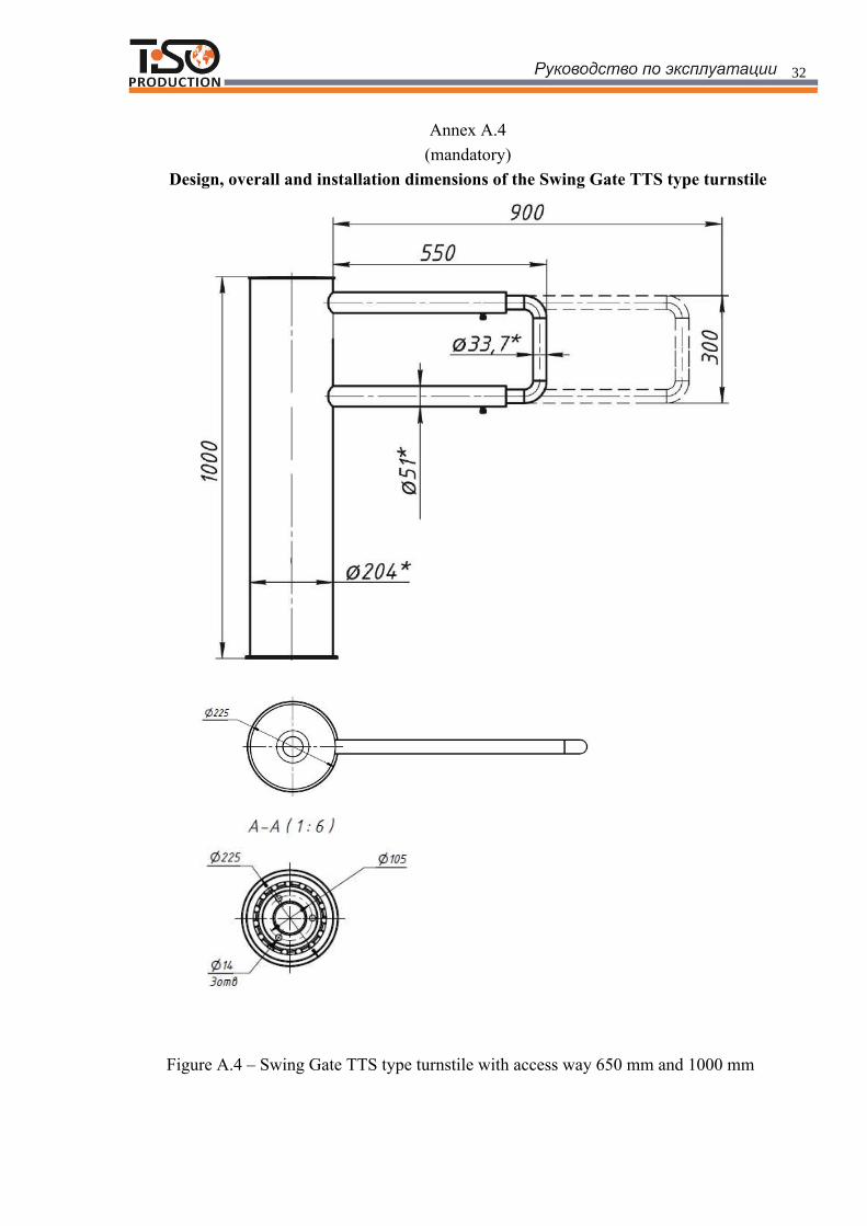
Annex А.4(mandatory)
Design, overall and installation dimensions of the Swing Gate TTS type turnstile
Figure А.4 – Swing Gate TTS type turnstile with access way 650 mm and 1000 mm

33
Annex B
(mandatory)
Control panel and connection diagram
1 – control panel housing ;3 – front face;3,5 – access direction LED displays4 – "SINGLE ACCESS" mode control button;
6 – "FREE ACCESS" mode switch;7 – controller connection terminals
Figure B.1 – Control panel AUIA.114.22.00.00

34
Continued Annex B
Control panel and connection diagram
Figure B.2 – Connection diagram of control panel AUIA.114.22.00.00

35
11
10
6
7
24
25
1 2
22
23
12
13
8
9
17
18
20
19
4-2
4-3
5-3
4-3
20
5-4
4-2
17
18
195-1 4-1
5 4
4
5
32-1
1-1
2-1
1-1
2
1
3
6
7
85
4-4
9
10
115-6
5-112
134-4
4-1
WIRING DIAGRAM OF THE TURNSTILE
Figure В.1 – Wiring diagram of the turnstile connection
Annex C (mandatory)
Wiring diagram of the Swing Gate TTS type servo-operated turnstile

36
TURNSTILE
12
34
56
78
910
11
12
34
56
78
910
11
12
12
34
5
6
78
910
11
12
34
5
6
78
910
11
12
1212
LED “Closed A”
LED “Opened A”
+12 V
“Open A”
GND
“Open B”
LED “Opened B”
LED “Closed B”
+12 V“Open A”(ACS)
“Open B”(ACS)
GND
RELAY 1
RELAY 2
NC
COM
NO
NC
COM
NO
Figure D.1 – Wiring diagram of the turnstile connection to ACS
Annex D.1
(mandatory)
Wiring diagram of the turnstile connection to access control system (ACS)
WIRING DIAGRAM OF THE TURNSTILE CONNECTION TO ACCESS CONTROL SYSTEM
37
TURNSTILE
1
2
34
56
78
9
10
1112
34
56
78
9
10
1112
1
234
56
78
9
10
1112
34
56
78
9
10
1112
1212
LED “Closed A”
LED “Opened A”
+12 V“Open A”
GND
“Open B”
LED “Opened B”
LED “Closed B”
+12 V
“Open A”(ACS)
“Open B”(ACS)GND
RELAY 1
NC
COM
NO
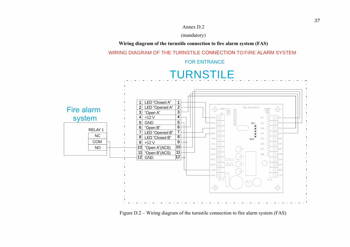
WIRING DIAGRAM OF THE TURNSTILE CONNECTION TO FIRE ALARM SYSTEM
Annex D.2
(mandatory)
Wiring diagram of the turnstile connection to fire alarm system (FAS)
Figure D.2 – Wiring diagram of the turnstile connection to fire alarm system (FAS)

38
W IR
IN
G D
IA
G
R
A
M O
F T
H
E T
U
R
N
S
T
IL
E CONNECTION TO F
IR
E ALARM S
Y
S
T
E
M
TURNSTILE
1
2
3
4
5
6
7
8
9
10
11
12
3
4
5
6
7
8
9
10
11
12
1
2
3
4
5
6
7
8
9
10
11
12
3
4
5
6
7
8
9
10
11
12
1
2
1
2
LED “Closed A”
LED “Opened A”
+12 V
“Open A”
GND
“Open B”
LED “Opened B”
LED “Closed B”
+12 V
“Open A”(ACS)
“Open B”(ACS)
GND
RELAY 1
NC
COM
NO
TURNSTILE
1
2
3
4
5
6
7
8
9
10
11
12
3
4
5
6
7
8
9
10
11
12
1
2
3
4
5
6
7
8
9
10
11
12
3
4
5
6
7
8
9
10
11
12
1
2
1
2
LED “Closed A”
LED “Opened A”
+12 V
“Open A”
GND
“Open B”
LED “Opened B”
LED “Closed B”
+12 V
“Open A”(ACS)
“Open B”(ACS)
GND
Annex D.3
(mandatory)
Wiring diagram of the turnstile connection to fire alarm system (FAS)
Figure D.3 – Wiring diagram of the turnstile connection to fire alarm system (FAS)

39
TURNSTILE
12
3
4
56
7
8
910
1112
3
4
56
7
8
910
1112
12
3
4
56
7
8
910
1112
3
4
56
7
8
910
1112
1212
LED “Closed A”LED “Opened A”
+12 V
“Open A”
GND
“Open B”
LED “Opened B”
LED “Closed B”
+12 V“Open A”(ACS)
“Open B”(ACS)GND
RELAY 1
NC
COM
NO
WIRING DIAGRAM OF THE TURNSTILE CONNECTION TO FIRE ALARM SYSTEM
Annex D.4
(mandatory)
Wiring diagram of the turnstile connection to fire alarm system (FAS)
.4 –

40
TURNSTILE
1
2
3
4
5
6
7
8
9
10
11
12
3
4
5
6
7
8
9
10
11
12
1
2
3
4
5
6
7
8
9
10
11
12
3
4
5
6
7
8
9
10
11
12
1
2
1
2
LED “Closed A”
LED “Opened A”
+12 V
“Open A”
GND
“Open B”
LED “Opened B”
LED “Closed B”
+12 V
“Open A”(ACS)
“Open B”(ACS)
GND
RELAY 1
NC
COM
NO
TURNSTILE
1
2
3
4
5
6
7
8
9
10
11
12
3
4
5
6
7
8
9
10
11
12
1
2
3
4
5
6
7
8
9
10
11
12
3
4
5
6
7
8
9
10
11
12
1
2
1
2
LED “Closed A”
LED “Opened A”
+12 V
“Open A”
GND
“Open B”
LED “Opened B”
LED “Closed B”
+12 V
“Open A”(ACS)
“Open B”(ACS)
GND
Figure D.5 – Wiring diagram of the turnstile connection to fire alarm system (FAS)
W IR IN G D IA G R A M O F T H E T U R N S T IL E CONNECTION T O F IR E ALARM S Y S T E M
Annex D.5
(mandatory)
Wiring diagram of the turnstile connection to fire alarm system (FAS)

41
W I R I N G D I A G R A M
TURNSTILE
12
34
5
6
78
910
11
12
34
5
6
78
910
11
12
12
34
5
6
78
910
1112
34
5
6
78
910
1112
1
2
1
2LED “Closed A”
LED “Opened A”
+12 V“Open A”
GND
“Open B”
LED “Opened B”
LED “Closed B”
+12 V
“Open A”(ACS)
“Open B”(ACS)
GND
3
4
56
7
8
12
Annex D.4
(mandatory)
Wiring diagram of the turnstile connection to control panel
O F T H E T U R N S T I L E CONNECTION T O C O N T R O PANEL
Figure D.6 – Wiring diagram of the turnstile connection to control panel