tip: 3425 kittle loco with lp4.0 micro conversion and...
TRANSCRIPT

Tip: 3425 Kittle Loco with LP4.0 Micro Conversion and LED Lighting Date: 07-02-2012, Corrections 22-07-2012 Addition 25-09-2016 Link added 03-03-2017
http://members.ozemail.com.au/~rossstew/rms/marklin.html 1
Hi All,
This is the last of Rudolf’s LokPilot Micro V4.0 decoder conversions. He asked me to convert his
Märklin Delta 3425 steam locomotive and wanted to improve the lighting effects for the cabin, change the
yellow LED’s for the front and rear lights to white LED’s and to have a prototypical speed of 60 km/h.
The results proved worthwhile and Rudolf’s loco is back on his favourite list.
Warning: - You undertake the following modifications at your own risk. This is not for the faint hearted
as it requires fine soldering skills, milling of the chassis to allow clearance for wires and modifications to
the existing PCB.
Addition 25-09-2016
Please see last page for a few problems that I had to fine tune on this locomotive.
Parts required:-
Part Number Supplier Description Quantity
54683 ESU ESU LokPilot Micro V4.0 Decoder 1
51940 ESU White cable, 0.5mm diameter, AWG36, 10m 1
51942 ESU Black cable, 0.5mm diameter, AWG36, 10m 1
51943 ESU Red cable, 0.5mm diameter, AWG36, 10m 1
51944 ESU Orange cable, 0.5mm diameter, AWG36, 10m 1
51946 ESU Grey cable, 0.5mm diameter, AWG36, 10m 1
51947 ESU Yellow cable, 0.5mm diameter, AWG36, 10m 1
51949 ESU Blue cable, 0.5mm diameter, AWG36, 10m 1
102-3035 Element14 Harwin SIL Socket 32Way D01-9973242 1
108-1177 Element14 1N4148 Signal diode 2
934-1102 Element14 1K MF25 Resistor 0.25W, 1% 2
120-1478 Element14 Protoboard 100x220 or similar 1
0805LWCT Ledz.com 0805 white LED 4
PLCC2LW3CT Ledz.com PLCC2 warm white LED 2

Tip: 3425 Kittle Loco with LP4.0 Micro Conversion and LED Lighting Date: 07-02-2012, Corrections 22-07-2012 Addition 25-09-2016 Link added 03-03-2017
http://members.ozemail.com.au/~rossstew/rms/marklin.html 2
Mechanical Requirements for the Chassis, PCB and Interior Insert
First I stripped the locomotive down and removed the driving wheels at the motor end and the drive shaft
after marking the location for a 3mm hole indicated by the red arrow.
Using a 3mm drill, drill at the location indicated then de burr on both sides using a larger drill. The break
out slot from the 3mm hole is not required.
Replace the PCB and mark the location for the hole, remove and drill with a 3mm drill. Finally replace
the PCB then insert the interior detail, mark the hole, remove and drill with the same drill. Using side
cutters break out the hole in the interior detail as shown in the photo. At the location shown by the violet
arrow use a small file and undercut a small notch on the seat to allow the wires to clear the motor
flywheel.

Tip: 3425 Kittle Loco with LP4.0 Micro Conversion and LED Lighting Date: 07-02-2012, Corrections 22-07-2012 Addition 25-09-2016 Link added 03-03-2017
http://members.ozemail.com.au/~rossstew/rms/marklin.html 3
Protoboard (Vero Board) Interconnection Panel
The interconnection Vero board size is (9 foils x 7 holes) then cut to fit.
The black shapes indicate locations where to cut
the interconnection panel outline.
The black dot is an approximate location for a
2.5mm drill. The location for the hole should be
determined once the 3way SIL socket has been
fitted and plugged into the existing locomotive
PCB.
Red circle indicates 3x 2mm counter bore holes
from the non foil side to allow 1x SIL socket (3
pins) to sit flush with the Vero board. This is most
important to obtain the correct mounting distance.
On the foil side use a 3mm drill to cut the foil at
the locations marked with a green circle with a
cross.
ESU Wire Colours.
The Interconnection panel component side. The faint black indicates the centre line of the drive shaft.
The wide green line indicates approx 1mm clearance is required from the sides of the locomotive to allow
re fitting the decoder cover which also holds the collector shoe.
Cut out the Vero board as shown, fit the 3way SIL socket connector then plug into the locomotive PCB.
Now mark where the 2.5-3mm hole should be, remove and using a 2mm drill, drill the hole then enlarge it
with a round needle file so you get a nice fit over the screw mounting location.
Now try fitting the decoder cover/collector shoe holder and ensure it fits well without using any force.
Make any adjustments for a good fit then complete the Interconnection Panel and mount in place.
Description Colour
Motor L Grey
Motor R Orange
Ground Black
Centre Rail Red
+ Pole Blue
Head Light White
Rear Light Yellow
LP Micro Connection Points
Kittle PCB Wiring Connections

Tip: 3425 Kittle Loco with LP4.0 Micro Conversion and LED Lighting Date: 07-02-2012, Corrections 22-07-2012 Addition 25-09-2016 Link added 03-03-2017
http://members.ozemail.com.au/~rossstew/rms/marklin.html 4
Locomotive PCB Modifications
After drilling the 3mm hole I removed the yellow LED’s and replaced them with 0805 white LED’s with
the orientation as indicated by the black symbols.
Next I removed the two 560 ohm resistors (violet arrow) as they are not required.
Locomotive PCB Cut Track Modifications
Cut two very small parallel cuts at
each red mark with a very sharp
knife being careful not to cut the
other tracks and of course don’t cut
yourself. Remove the copper track
between the cuts with a soldering
iron.
Next at the yellow marks carefully
scratch the resist away from the
copper track and tin with some
solder.
PCB Circuit Connections to Interconnection Panel The +Pole can be linked across the two blue pads (removed resistor) and
the indicated wire link is required.
Below wires are shown at the correct locations.
3mm Hole
M
M FL
+Pole RL
Wire Link

Tip: 3425 Kittle Loco with LP4.0 Micro Conversion and LED Lighting Date: 07-02-2012, Corrections 22-07-2012 Addition 25-09-2016 Link added 03-03-2017
http://members.ozemail.com.au/~rossstew/rms/marklin.html 5
Interconnection Panel Wiring Harness
Insert the colour wires from the locomotive PCB through the hole ready for soldering to the
interconnection panel below.
Photo above shows the SIL connector socket to be
plugged into the pins from the locomotive PCB
(violet arrows). The yellow notch is where the
cables from the decoder must be run to connect to the interconnection panel (see top right photo as well).
The top right photo shows the location of the LP Micro which is a neat fit between the drive shaft and the
inside edge of the locomotive. This is held in place by hot melt glue, making sure there is an approx
clearance of 1mm (see wide green line)
The mounting screw has a small washer under it. This is used to make a connection for the chassis ground
on the two left most foils. Ensure the washer is isolated from the third foil from the left hand side by
drilling the isolating hole in the foil. The black wire from the decoder is soldered as the chassis ground.
Refer to page 3 for “LP Micro Connection Points” which should match the view above.
Bottom right photo shows the plastic centre rail isolator in place (red arrow). All wires from the
locomotive PCB are connected to the interconnection panel. Refer to page 3 for “LP Micro Connection
Points” which should match the view above.
Note: - The blue wire (blue arrow) is redundant as the +pole is on the middle pin of the SIL connector. I
have marked it as a dotted line, Refer to page 3 for “Kittle PCB Wiring Connections.”

Tip: 3425 Kittle Loco with LP4.0 Micro Conversion and LED Lighting Date: 07-02-2012, Corrections 22-07-2012 Addition 25-09-2016 Link added 03-03-2017
http://members.ozemail.com.au/~rossstew/rms/marklin.html 6
Cabin LED Lighting
Two warm white PLCC2 LEDS with 1k resistors were used for the interior lighting and connected as
shown above. I have put two black dots on the seats (red arrow) to indicate the resistor side in case the
LED lights are removed for servicing.
The yellow circle indicates the top of the motor, in case it is removed for any reason.
The blue arrow shows where the notch in the seat allows for the wires just to clear the motor flywheel.
Body Shell Modifications
Machine down approx 1mm in the areas shown by the red and blue arrows and de burr the edges of the
milled areas, this will allow just enough clearance above the locomotive PCB so you don’t pinch any
wires or create any short circuits. Apply a small piece of electrical tape to both sides (shown by red
arrow)
Fit the body shell on and test that there are no short circuits between the body and the interconnection
panel connections also inspect the wires to make sure none are pinched.
If you are happy there are no problems it’s time to programme the decoder.
a
k
a
k
Tip: 3425 Kittle Loco with LP4.0 Micro Conversion and LED Lighting Date: 07-02-2012, Corrections 22-07-2012 Addition 25-09-2016 Link added 03-03-2017
http://members.ozemail.com.au/~rossstew/rms/marklin.html 7
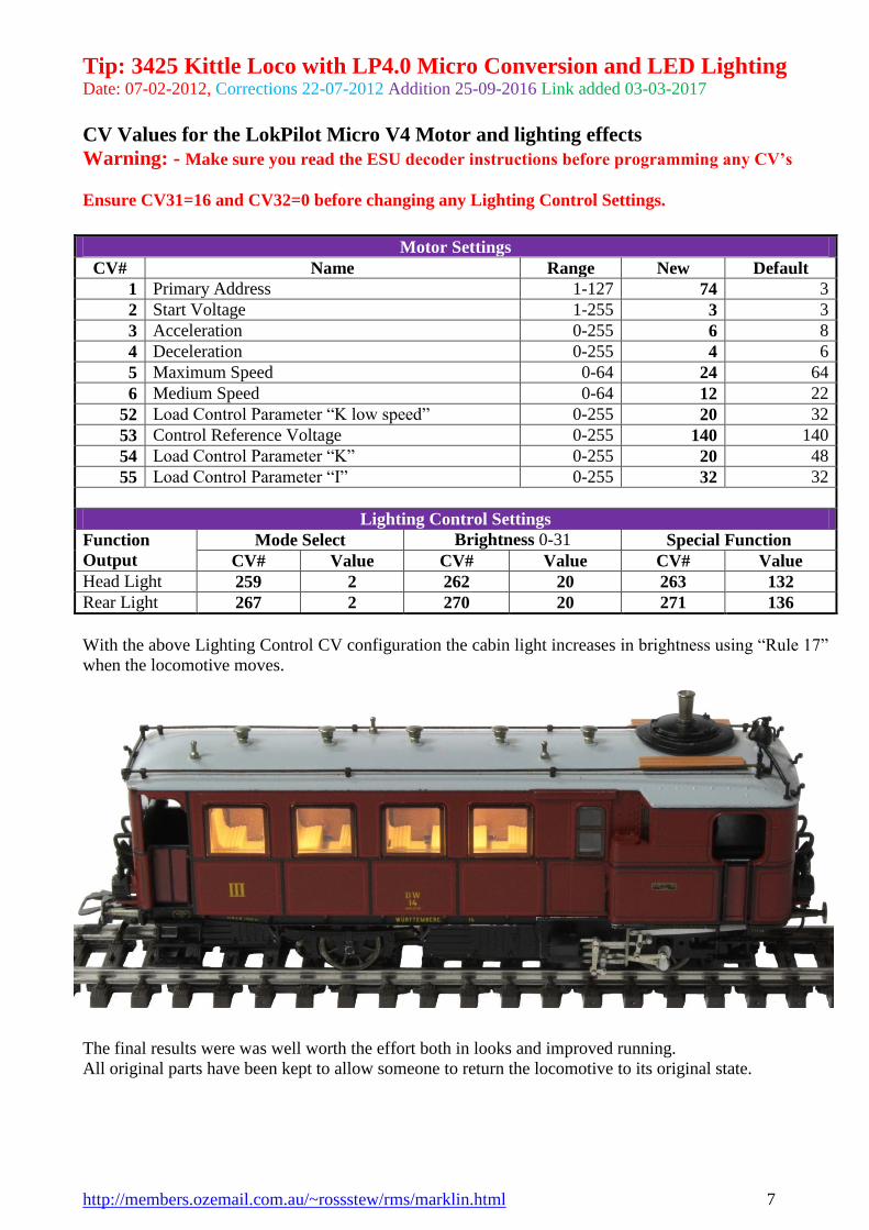
CV Values for the LokPilot Micro V4 Motor and lighting effects
Warning: - Make sure you read the ESU decoder instructions before programming any CV’s
Ensure CV31=16 and CV32=0 before changing any Lighting Control Settings.
With the above Lighting Control CV configuration the cabin light increases in brightness using “Rule 17”
when the locomotive moves.
The final results were was well worth the effort both in looks and improved running.
All original parts have been kept to allow someone to return the locomotive to its original state.
Motor Settings
CV# Name Range New Default
1 Primary Address 1-127 74 3
2 Start Voltage 1-255 3 3
3 Acceleration 0-255 6 8
4 Deceleration 0-255 4 6
5 Maximum Speed 0-64 24 64
6 Medium Speed 0-64 12 22
52 Load Control Parameter “K low speed” 0-255 20 32
53 Control Reference Voltage 0-255 140 140
54 Load Control Parameter “K” 0-255 20 48
55 Load Control Parameter “I” 0-255 32 32
Lighting Control Settings
Function
Output
Mode Select Brightness 0-31 Special Function
CV# Value CV# Value CV# Value
Head Light 259 2 262 20 263 132
Rear Light 267 2 270 20 271 136

Tip: 3425 Kittle Loco with LP4.0 Micro Conversion and LED Lighting Date: 07-02-2012, Corrections 22-07-2012 Addition 25-09-2016 Link added 03-03-2017
http://members.ozemail.com.au/~rossstew/rms/marklin.html 8
Other Useful Information
TrainAnimator file that you can use with TrainController.
3425.yra
Tip: 3425 Kittle Loco with LP4.0 Micro Conversion and LED Lighting Date: 07-02-2012, Corrections 22-07-2012 Addition 25-09-2016 Link added 03-03-2017
http://members.ozemail.com.au/~rossstew/rms/marklin.html 9
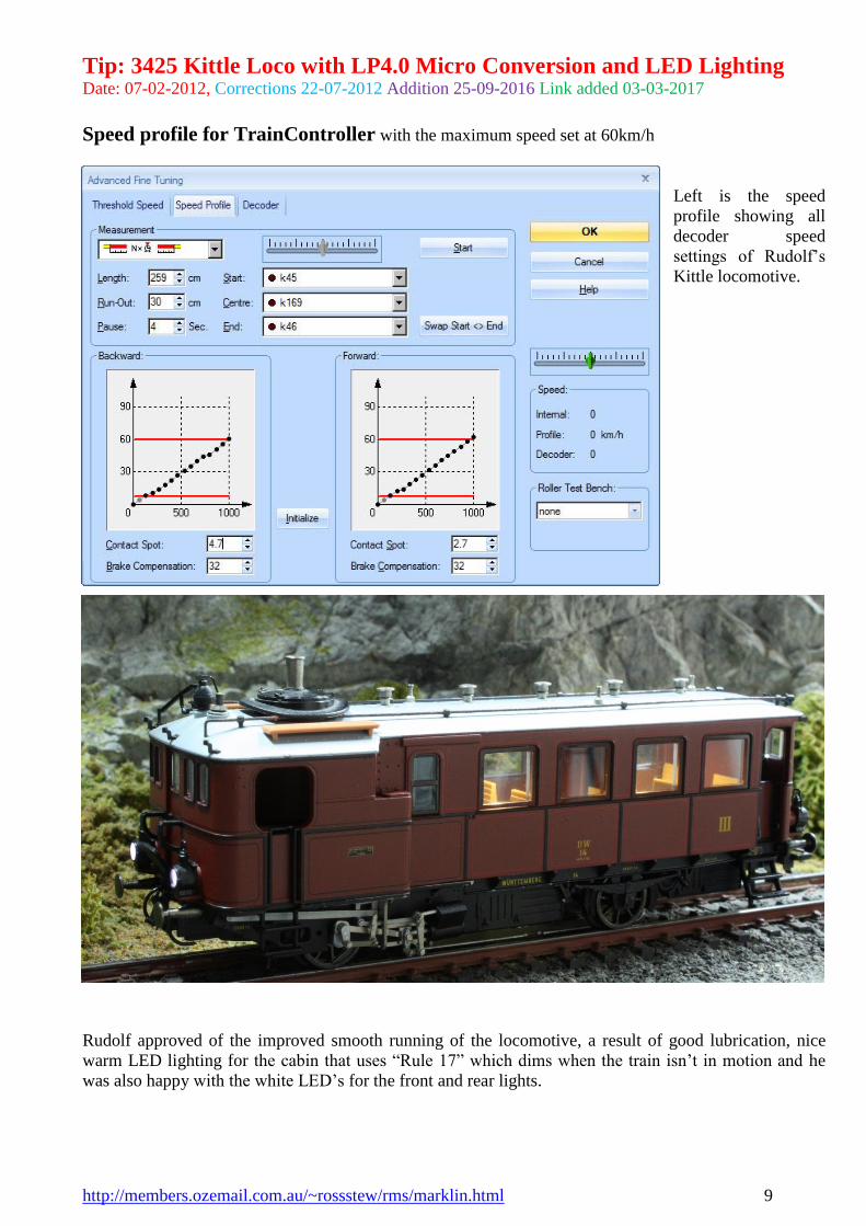
Speed profile for TrainController with the maximum speed set at 60km/h
Left is the speed
profile showing all
decoder speed
settings of Rudolf’s
Kittle locomotive.
Rudolf approved of the improved smooth running of the locomotive, a result of good lubrication, nice
warm LED lighting for the cabin that uses “Rule 17” which dims when the train isn’t in motion and he
was also happy with the white LED’s for the front and rear lights.

Tip: 3425 Kittle Loco with LP4.0 Micro Conversion and LED Lighting Date: 07-02-2012, Corrections 22-07-2012 Addition 25-09-2016 Link added 03-03-2017
http://members.ozemail.com.au/~rossstew/rms/marklin.html 10
Addition 25-09-2016
After some time running this locomotive it started to exhibit poor running by stopping after a few
seconds.
There were two problems found.
1. The motor brushes had poor contact with the contact springs.
As the contact springs are quite
long I was able to bend each
spring over to the inside closest to
the brush holder by about 3mm to
double the contact thickness. This
was just enough to apply more
pressure to each brush to stop the
intermittent contact.
2. The collector shoe contact pin was loose because of a dry solder
joint caused by possible flexing of the pin when trying to fit the
collector shoe assembly.
The mounting of the collector shoe pin in the PCB is very poor as it is too short to get a nice flow
of solder around the pin as shown. I soldered a component lead off cut into the hole of the pin to
allow the wire to protrude through the PCB hole then resoldered the pin onto the PCB.
If this fails again I will remove the contact pin and solder a wire direct to the collector shoe.
Supplement Article by Ed Lekanides using a LokSound Micro.
As always enjoy your model trains.