tio-541 series - lycoming engines · lubrication system the lubrication system is of the pressure...
TRANSCRIPT

Operator�s Manual
Lycoming
TIO-541 Series
Approved by FAA
3rd Edition Part No. 60297-13
652 Oliver StreetWilliamsport, PA. 17701 U.S.A.570/323-6181
December 2007
TIO-541 Series Operator�s Manual Lycoming Part Number: 60297-13
©2007 by Lycoming. All rights reserved.Lycoming and �Powered by Lycoming� are trademarks or registered trademarks of Lycoming.
All brand and product names referenced in this publication are trademarks or registeredtrademarks of their respective companies.
For additional information:
Mailing address:
Lycoming Engines652 Oliver StreetWilliamsport, PA 17701 U.S.A.
Phone:
Factory: 570-323-6181Sales Department: 570-327-7268Fax: 570-327-7101
Lycoming�s regular business hours are Monday through Friday from 8:00 AMthrough 5:00 PM Eastern Time (-5 GMT)
Visit us on the World Wide Web at:http://www.lycoming.com

LYCOMING OPERATOR�S MANUAL
ATTENTION
OWNERS, OPERATORS AND MAINTENANCE PERSONNEL
This operator�s manual contains a description of the engine, its specifications, and detailed information onhow to operate and maintain it. Such maintenance procedures that may be required in conjunction withperiodic inspections are also included. This manual is intended for use by owners, pilots and maintenancepersonnel responsible for care of Lycoming powered aircraft. Modifications and repair procedures arecontained in Lycoming overhaul manuals; maintenance personnel should refer to these for such procedures.
SAFETY WARNING
Neglecting to follow the operating instructions and to carry out periodic maintenance procedures can resultin poor engine performance and power loss. Also, if power and speed limitations specified in this manualare exceeded, for any reason, damage to the engine and personal injury can happen. Consult your localFAA approved maintenance facility.
SERVICE BULLETINS, INSTRUCTIONS, AND LETTERS
Although the information contained in this manual is up-to-date at time of publication, users are urged tokeep abreast of later information through Lycoming Service Bulletins, Instructions and Service Letters,which are available for all Lycoming distributors or, from the factory by subscription. Consult the latestrevision of Service Letter No. L114 for subscription information.
SPECIAL NOTE
The illustrations, pictures and drawings shown in this publication are typical of the subject matter theyportray; in no instance are they to be interpreted as examples of any specific engine, equipment or partthereof.
iii

LYCOMING OPERATOR�S MANUAL
IMPORTANT SAFETY NOTICE
Proper service and repair is essential to increase the safe, reliable operation of all aircraft engines. Theservice procedures recommended by Lycoming are effective methods for performing service operations.Some of these service operations require the sue of tools specially designed for the task. These special toolsmust be used when and as recommended.
It is important to note that most Lycoming publications contain various Warnings and Cautions whichmust be carefully read in order to minimize the risk of personal injury or the use of improper servicemethods that may damage the engine or render it unsafe.
It is also important to understand that these Warnings and Cautions are not all inclusive. Lycoming couldnot possibly know, evaluate or advise the service trade of all conceivable ways in which service might bedone or of the possible hazardous consequences that may be involved. Accordingly, anyone who uses aservice procedure must first satisfy themselves thoroughly that neither their safety nor aircraft safety will bejeopardized by the service procedure they select.
iv

LYCOMING OPERATOR�S MANUAL
TABLE OF CONTENTS
Page
SECTION 1 DESCRIPTION 1-1
SECTION 2 SPECIFICATIONS 2-1
SECTION 3 OPERATING INSTRUCTIONS 3-1
SECTION 4 PERIODIC INSPECTIONS 4-1
SECTION 5 MAINTENANCE PROCEDURES 5-1
SECTION 6 TROUBLE-SHOOTING 6-1
SECTION 7 INSTALLATION AND STORAGE 7-1
SECTION 8 TABLES 8-1
v

LYCOMING OPERATOR�S MANUAL
¾ Left Front View � TIO-541-E1B4
Right Side View � TIO-541-A1A
vi

LYCOMNG OPERATOR�S MANUAL
¾ Right Rear View � TIO-541-E1B4
WARNING
THESE ENGINES ARE EQUIPPED WITH A DYNAMIC COUNTERWEIGHT SYSTEM ANDMUST BE OPERATED ACCORDINGLY; AVOID HIGH ENGINE SPEED, LOWMANIFOLD PRESSURE OPERATION. USE A SMOOTH STEADY MOVEMENT OF THETHROTTLE (AVOID RAPID OPENING AND CLOSING). IF THIS WARNING IS NOTHEEDED, THERE COULD BE SEVERE DAMAGE TO THE COUNTERWEIGHTS,ROLLERS AND BUSHINGS.
vii

This Page Intentionally Left Blank.

LYCOMING OPERATOR�S MANUAL
SECTION 1DESCRIPTION
Page
General.......................................................................................................................................................... 1-1
Cylinders....................................................................................................................................................... 1-1
Valve Operating Mechanism ...................................................................................................................... 1-1
Crankshaft .................................................................................................................................................... 1-1
Crankcase ..................................................................................................................................................... 1-1
Oil Sump ....................................................................................................................................................... 1-1
Connecting Rods .......................................................................................................................................... 1-1
Pistons ........................................................................................................................................................... 1-2
Gears ............................................................................................................................................................. 1-2
Cooling System............................................................................................................................................. 1-2
Lubrication System...................................................................................................................................... 1-2
Induction System.......................................................................................................................................... 1-2
Turbocharger System .................................................................................................................................. 1-2
Ignition System............................................................................................................................................. 1-2
Propeller Governor Drives.......................................................................................................................... 1-2
Accessory Drives .......................................................................................................................................... 1-2

This Page Intentionally Left Blank.

LYCOMING OPERATOR�S MANUAL SECTION 1 TIO-541 SERIES DESCRIPTION
SECTION 1
DESCRIPTION
General � The Lycoming TIO-541 aircraft engine is a six cylinder, direct drive, horizontally opposed, wetsump, fuel injected, turbocharged, air-cooled model with side mounted accessories and incorporating pistoncooling oil jets in the crankcase.
In referring to the location of the various engine components, the parts will be described in theirrelationship to the engine as installed in the airframe. Thus the power take-off section will be considered thefront and the sump section will be considered the bottom. References to the left and right sides of the engineare made with the observer facing the rear of the engine. Thus the front cylinder on the left bank is number 1and the rear cylinder number 5. The front cylinder on the right bank is number 2 and the rear cylinder isnumber 6. The direction of rotation for the accessory drives is determined by the observer when facing theaccessory mounting pad.
Cylinders � The cylinders are of air-cooled construction with the two major parts, head and barrel, screwedand shrunk together. The heads are made from an aluminum casting with a fully machined combustionchamber. The cylinder barrels are machined from chrome nickel molybdenum steel forgings with deepintegral cooling fins. The interior of the barrel is nitrided; requiring the use of chrome plated piston rings.
Rocker shaft bearing supports and the rocker box housings are cast integrally with the cylinder head. Theintake and exhaust valves are angled. The intake port is on the top and the exhaust port on the bottom of thecylinder. Long reach spark plugs are employed.
Valve Operating Mechanism � The camshaft is located parallel to and below the crankshaft and operates inaluminum bearings. The camshaft actuates the valves by means of hydraulic lifters, which automaticallykeep the valve clearance at zero. The valve rockers are supported on full floating steel shafts. The valvesprings bear against hardened steel seats.
Crankshaft � The crankshaft is made from a chrome nickel molybdenum steel forging. All bearing journalsurfaces are nitrided. The crankshaft is fitted with pendulum type dynamic counterweights.
Crankcase � The crankcase consists of two reinforced aluminum alloy castings divided vertically at thecenter line of the engine and fastened together by means of thru bolts and nuts. The mating surfaces of thecrankcase are joined without the use of a gasket, and the main bearing bores are machined for use ofprecision type main bearing inserts.
Oil Sump � The oil sump fastens to the bottom of the crankcase. It incorporates two oil drain plugs, the oilsuction screen housing, and a boss for mounting the fuel drain manifold assembly.
Connecting Rods � The connecting rods are made in the form of �H� sections from alloy steel forgings. They have replaceable bearing inserts in the crankshaft ends and bronze bushings in the piston ends. Thebearing caps on the crankshaft ends of the rods are retained by means of two bolts and nuts through eachcap.
1-1

SECTION 1 LYCOMING OPERATOR�S MANUAL DESCRIPTION TIO-541 SERIES
Pistons � The pistons are machined from an aluminum alloy. Two compression rings and an oil regulatingring are located above the piston pin. The pistons are equipped with full floating type pins with a pluglocated at each end of the pin.
Gears � The gears are of conventional type and are precision machined. They are hardened to insure longlife and satisfactory operating qualities.
Cooling System � The air pressure cooling system is actuated by the forward speed of the aircraft. Bafflesare provided to build up a pressure between the cowling and the cylinders, thus forcing the air through thecylinder fins. The air is then exhausted through gills usually located at the rear of the engine cowling.
Lubrication System � The lubrication system is of the pressure wet sump type.
Induction System � This engine employs a Bendix RSA type fuel injection system.
The fuel injection system is based on the principle of measuring air flow and uses the air flow signal in astem type regulator to convert the air force into a fuel force. This fuel force (fuel pressure differential) whenapplied across the fuel metering section, makes fuel flow proportional to air flow. A manual mixture controland idle cut-off are provided.
Turbocharger System � The turbocharger system is mounted as an integral part of the engine. Its turbineutilizes the engine exhaust gases to drive a compressor, which furnishes air to the engine induction systemand air for pressurized cabins.
The variable pressure controller senses the compressor discharge pressure (deck pressure) and in turnregulates the oil pressure, which controls the position of the exhaust bypass valve located on the engineexhaust. The desired compressor discharge pressure is determined by positioning the throttle control, whichis linked to the controller cam. Engine oil pressure is utilized as the �muscle� for this control system.
The variable pressure controller employed on the �A� series has two settings, the maximum boost setting and the minimum boost setting. The maximum setting is 37 in. hg. ± 0.5, the minimum setting is 24 � 26 in. hg.
The action of the turbocharger control system is automatic and modulates continuously as engine power,speed and altitude are varied. Bleed air to the cabin, on models �A1A, -E1A4 and �E1C4, is controlled by a sonic nozzle that limits the flow of air to the cabin.
Ignition System � Dual ignition is furnished by two Scintilla �1200 series magnetos. The S6LN-1208 magneto is a retard breaker magneto providing a fixed retard and a long duration spark for easier starting.The S6RN-1209 is a conventional magneto, which is grounded out at the time the engine is started. A sourceof DC power and a starting vibrator are required to complete the installation. The �1200 series magnetos incorporate an integral feed-thru capacitor and require no external noise filter in the ground leads.
Propeller Governor Drive � A propeller governor drive is furnished as standard equipment. The propellergovernor mounting pad is located on the lower right front side of the crankcase.
Accessory Drives � The following accessory drives are furnished as standard equipment: starter, alternator,propeller governor, vacuum pump, hydraulic pump, tachometer and fuel pump. The �E� series incorporates a Freon compressor drive that may be used for air conditioning.
1-2

LYCOMING OPERATOR�S MANUAL
SECTION 2SPECIFICATIONS
Page
Specifications � TIO-541-E Series .............................................................................................................. 2-2
Specifications � TIO-541-A Series.............................................................................................................. 2-3
Detail Weights � TIO-541-A Series
Engine (Standard)..................................................................................................................................... 2-4
Engine Installation Standard Parts......................................................................................................... 2-4
Accessories, Drives and Optional Parts .................................................................................................. 2-4
Detail Weights � TIO-541-E1A4, -E1B4, -E1C4
Engine (Standard)..................................................................................................................................... 2-5
Detail Weights � TIO-541-E1D4
Engine (Standard)..................................................................................................................................... 2-6
Detail Weights � TIO-541-E Series
Engine Installation Standard Parts......................................................................................................... 2-6
Accessories, Drives and Optional Parts .................................................................................................. 2-6

This Page Intentionally Left Blank.

LYCOMING OPERATOR�S MANUAL SECTION 2 TIO-541 SERIES SPECIFICATIONS
SECTION 2
SPECIFICATIONS
NOTE
The model specifications shown on the following pages of this section are divided accordingto model designation. When differences among models can be clearly stated, thespecifications of more than one model are combined in a single group; otherwise, eachmodel has its specifications listed separately. Also, as additional models are added to thisseries, new specification pages containing data pertinent to the new models will be added.
2-1

SECTION 2 LYCOMING OPERATOR�S MANUAL SPECIFICAIONS TIO-541 SERIES
SPECIFICATIONS
TIO-541-E SERIES
FAA Type Certificate ..............................................................................................................................E10EARated horsepower, RPM, Alt. ......................................................................................... 380 @ 2900/15,000 ft.Performance Cruise horsepower, RPM, Alt. .................................................................. 300 @ 2750/21,000 ft.Economy Cruise, horsepower, RPM................................................................................................247 @ 2650Bore, inches.................................................................................................................................................5.125Stroke, inches..............................................................................................................................................4.375Displacement, cubic inches.........................................................................................................................541.5Compression ratio ....................................................................................................................................... 7.3:1Fuel Injector, Bendix type...............................................................................................................RSA-10DB1Magnetos, (1) Scintilla (right).......................................................................................................... S6RN-1209Magnetos, (1) Scintilla (left).............................................................................................................S6LN-1208Firing order .......................................................................................................................................1-4-5-2-3-6Spark occurs, degrees BTC..............................................................................................................................20Valve rocker clearance (hydraulic liters collapsed)............................................................................. .040-.105Dimensions:
Height, inches ..........................................................................................................................................25.17Width, inches ...........................................................................................................................................35.66Length, inches ..........................................................................................................................................52.07
Accessory Drive Drive Ratio *Direction of Rotation
Starter 16.556:1 CounterclockwiseAlternator 3.250:1 ClockwiseOptional Generator Drive 1.910:1 ClockwiseOptional Generator Drive 2.500:1 ClockwiseVacuum Pump 1.000:1 ClockwiseHydraulic Pump 1.000:1 CounterclockwiseTachometer 0.500:1 CounterclockwisePropeller Governor 0.895:1 CounterclockwiseFuel Pump 1.000:1 Counterclockwise
* - Facing drive pad.
2-2

LYCOMING OPERATOR�S MANUAL SECTION 2 TIO-541 SERIES SPECIFICATIONS
SPECIFICATIONS (CONT.)
TIO-541-A SERIES
FAA Type Certificate ..............................................................................................................................E10EARated horsepower, RPM, Alt. ......................................................................................... 310 @ 2575/15,000 ft.Performance Cruise (75% rated horsepower), Alt. .......................................................................230/25,000 ft.Economy Cruise (65% rated horsepower) .....................................................................................................185Bore, inches.................................................................................................................................................5.125Stroke, inches..............................................................................................................................................4.375Displacement, cubic inches.........................................................................................................................541.5Compression ratio ....................................................................................................................................... 7.3:1Fuel Injector, Bendix type...............................................................................................................RSA-10AD1Magnetos, (1) Scintilla (right).......................................................................................................... S6RN-1209Magnetos, (1) Scintilla (left).............................................................................................................S6LN-1208Firing order .......................................................................................................................................1-4-5-2-3-6Spark occurs, degrees BTC..............................................................................................................................20Valve rocker clearance (hydraulic lifters collapsed) ........................................................................... .040-.105Dimensions:
Height, inches ..........................................................................................................................................21.38Width, inches ...........................................................................................................................................34.25Length, inches ..........................................................................................................................................49.09
Accessory Drive Drive Ratio *Direction of Rotation
Starter 16.556:1 CounterclockwiseAlternator 3.250:1 ClockwiseOptional Generator Drive 1.910:1 ClockwiseOptional Generator Drive 2.500:1 ClockwiseVacuum Pump 1.500:1 ClockwiseHydraulic Pump 1.500:1 CounterclockwiseTachometer 0.500:1 CounterclockwisePropeller Governor 0.895:1 CounterclockwiseFuel Pump 1.000:1 Counterclockwise
* - Facing drive pad.
2-3

SECTION 2 LYCOMING OPERATOR�S MANUAL SPECIFICAIONS TIO-541 SERIES
DETAIL WEIGHTS
TIO-541-A SERIES
1. ENGINE (STANDARD)
Basic engine ..............................................................................................................................................421.32Turbocharger, AiResearch Model T1823 ...................................................................................................48.25Mounting bracket, exhaust manifold, controller, oil lines and baffles .......................................................36.50Fuel injector, Bendix RSA-10AD1...............................................................................................................8.00Magneto, Scintilla S6LN-1208 .....................................................................................................................5.85Magneto, Scintilla S6RN-1209.....................................................................................................................5.75Oil cooler ......................................................................................................................................................4.50Oil filter and adapter .....................................................................................................................................2.50Spark plugs, shielded ....................................................................................................................................3.00Ignition system, shielded ..............................................................................................................................5.40Starter and alternator drive............................................................................................................................6.53Starter, 3.38:1, geared, Prestolite with Bendix unit ....................................................................................16.90Alternator, Delco-Remy 12V., 70A., with mounting bracket.....................................................................13.00Intercylinder cooling baffles .........................................................................................................................1.50
Standard Engine Dry Weight (Pounds).....................................................................................................579.00
2. ENGINE INSTALLATION STANDARD PARTS
Starter switch, magnetic................................................................................................................................1.16Transistor voltage regulator, 12V. ................................................................................................................1.25Overvoltage relay, 12V....................................................................................................................................85
Weight of Installation Parts ..........................................................................................................................3.26
3. ACCESSORIES, DRIVES AND OPTIONAL PARTS
Alternator, Prestolite, 12V., 40A., with bracket .........................................................................................13.0024V., 50A., with bracket.........................................................................................13.00
Starter, Prestolite, 24V................................................................................................................................16.90Cylinder Base Thermocouples......................................................................................................................0.16Cylinder Head Thermocouples, Bayonet Type.............................................................................................0.59Rear Dynafocal Mounting Brackets..............................................................................................................9.50Bed-Type Mounting Brackets.......................................................................................................................4.60
2-4

LYCOMING OPERATOR�S MANUAL SECTION 2 TIO-541 SERIES SPECIFICATIONS
DETAIL WEIGHTS (CONT.)
TIO-541-E1A4, -E1B4
1. ENGINE (STANDARD)
Basic engine ..............................................................................................................................................452.51Turbocharger, AiResearch Model T8123 ...................................................................................................48.25Mounting bracket, exhaust manifold, exhaust bypass valve, controller, oil lines and baffles....................43.50Fuel injector, Bendix RSA-10DB1...............................................................................................................8.00Magneto, Scintilla S6LN-1208 .....................................................................................................................5.85Magneto, Scintilla S6RN-1209.....................................................................................................................5.75Oil cooler ....................................................................................................................................................10.50Oil filter and adapter .....................................................................................................................................3.50Spark plugs, shielded ....................................................................................................................................3.00Ignition system, shielded ..............................................................................................................................3.86Starter and alternator drive............................................................................................................................6.53Starter, 3.38:1 geared, Prestolite with mounting bracket............................................................................16.90Alternator, Prestolite 12V., 40A., with mounting bracket ..........................................................................13.00Intercylinder cooling baffles .........................................................................................................................1.50Compressor drive ..........................................................................................................................................2.35
Standard Engine Dry Weight (Pounds).....................................................................................................625.00
TIO-541-E1C4
Basic engine ..............................................................................................................................................453.76Turbocharger, AiResearch Model T1879 ...................................................................................................40.00Mounting bracket, exhaust manifold, exhaust bypass valve, controller, oil lines and baffles....................41.50Fuel injector, Bendix RSA-10DB1...............................................................................................................8.00Magneto, Scintilla S6LN-1208 .....................................................................................................................5.85Magneto, Scintilla S6RN-1209.....................................................................................................................5.75Oil cooler, de-congealing............................................................................................................................10.50Oil filter and adapter .....................................................................................................................................3.50Spark plugs, shielded ....................................................................................................................................3.00Ignition system, shielded ..............................................................................................................................3.86Starter and alternator drive............................................................................................................................6.53Starter, 3/38:1 geared, Prestolite with Bendix unit .....................................................................................16.90Alternator, Prestolite 12V., 40A., with mounting bracket ..........................................................................13.00Intercylinder cooling baffles .........................................................................................................................1.50Compressor drive ..........................................................................................................................................2.35
Standard Engine Dry Weight (Pounds).....................................................................................................616.00
2-5

SECTION 2 LYCOMING OPERATOR�S MANUAL SPECIFICATIONS TIO-541 SERIES
DETAIL WEIGHTS (CONT.)
TIO-541-E1D4
1. ENGINE (STANDARD) (CONT.)
Basic engine ..............................................................................................................................................451.76Turbocharger, AiResearch Model T1879 ...................................................................................................40.00Mounting bracket, exhaust manifold, exhaust bypass valve, controller, oil lines and baffles....................41.50Fuel injector, Bendix RSA-10DB1...............................................................................................................8.00Magneto, Scintilla S6LN-1208 .....................................................................................................................5.85Magneto, Scintilla S6RN-1209.....................................................................................................................5.75Oil cooler, de-congealing............................................................................................................................10.50Oil filter and adapter .....................................................................................................................................3.50Spark plugs, shielded ....................................................................................................................................3.00Ignition system, shielded ..............................................................................................................................3.86Starter and alternator drive............................................................................................................................6.53Starter, 3/38:1 geared, Prestolite with Bendix unit .....................................................................................16.90Alternator, Prestolite 12V., 40A., with mounting bracket ..........................................................................13.00Intercylinder cooling baffles .........................................................................................................................1.50Compressor drive ..........................................................................................................................................2.35
Standard Engine Dry Weight (Pounds).....................................................................................................614.00
2. ENGINE INSTALLATION STANDARD PARTS
TIO-541-E SERIES
Starter switch, magnetic................................................................................................................................1.16Transistor voltage regulator ..........................................................................................................................1.25Overvoltage relay, 12V.................................................................................................................................0.85
Weight of Installation Parts ..........................................................................................................................3.26
3. ACCESSORIES, DRIVES AND OPTIONAL PARTS
TIO-541-E SERIES
Alternator, Prestolite, 12V., 70A, with bracket ..........................................................................................13.0024V., 50A, with bracket..........................................................................................13.0024V., 100A., with bracket.......................................................................................22.00
Starter and alternator drive (Ford) ................................................................................................................6.53Starter and generator drive (Lear-Siegler) ....................................................................................................7.48Alternator brackets (Ford).............................................................................................................................0.85Generator brackets (Lear-Siegler).................................................................................................................1.25Starter, Prestolite, 24V................................................................................................................................16.90Cylinder Base Thermocouples......................................................................................................................0.16
2-6

LYCOMING OPERATOR�S MANUAL SECTION 2 TIO-541 SERIES SPECIFICATIONS
DETAIL WEIGHTS (CONT.)
3. ACCESSORIES, DRIVE AND OPTIONAL PARTS (CONT.)
TIO-541-E SERIES (CONT.)
Cylinder Head Thermocouples, Bayonet Type.............................................................................................0.59Rear Dynafocal Mounting Brackets..............................................................................................................9.50Bed-Type Mounting Brackets.......................................................................................................................4.60Transistor voltage regulator, 24V. ................................................................................................................1.25Overvoltage regulator, 24V. .........................................................................................................................0.85Turbocharger blanket ....................................................................................................................................1.00
2-7

This Page Intentionally Left Blank.

LYCOMING OPERATOR�S MANUAL
SECTION 3OPERATING INSTRUCTIONS
Page
General.......................................................................................................................................................... 3-1
Care of New Engine ..................................................................................................................................... 3-1
Fuel ................................................................................................................................................................ 3-1
Oil Change .................................................................................................................................................... 3-1
Prestarting Procedure ................................................................................................................................. 3-1
Starting Procedure....................................................................................................................................... 3-1
Cold Weather Starting ................................................................................................................................ 3-2
Ground Running and Warm-Up................................................................................................................ 3-2
Ground Check .............................................................................................................................................. 3-3
Operation in Flight ...................................................................................................................................... 3-3
Engine Shut-Down ....................................................................................................................................... 3-5
Engine Flight Chart ..................................................................................................................................... 3-5
Performance Curves .................................................................................................................................... 3-7

This Page Intentionally Left Blank.

LYCOMING OPERATOR�S MANUAL SECTION 3 TIO-541 SERIES OPERATING INSTRUCTIONS
SECTION 3
OPERATING INSTRUCTIONS
1. General. Close adherence to these instructions will greatly contribute to long life, economy andsatisfactory operation of the engine.
NOTE
YOUR ATTENTION IS DIRECTED IN PARTICULAR TO THE WARRANTIES THATAPPEAR IN THE FRONT OF THIS MANUAL REGARDING ENGINE SPEED, THE USEOF SPECIFIED FUELS, LUBRICANTS, REPAIRS AND ALTERATIONS. PERHAPS NOOTHER ITEM OF ENGINE OPERATION AND MAINTENANCE CONTRIBUTES QUITESO MUCH TO SATISFACTORY PERFORMANCE AND LONG LIFE AS THE CONSTANTUSE OF CORRECT GRADES OF FUEL AND OIL, CORRECT ENGINE TIMING ANDFLYING THE AIRPLANE AT ALL TIMES WITHIN THE SPEED AND POWER RANGESPECIFIED FOR THE ENGINE. DO NOT FORGET THAT VIOLATION OF THEOPERATION AND MAINTENANCE SPECIFICATIONS FOR YOUR ENGINE WILL NOTONLY VOID YOUR WARRANTY, BUT WILL SHORTEN THE LIFE OF YOUR ENGINEAFTER THE WARRANTY PERIOD HAS PASSED.
Care of New Engine � New engines have been carefully run-in by Lycoming and therefore no further break-in is necessary insofar as operation is concerned; however, new or newly overhauled engines should beoperated on multi-viscosity ashless dispersant oil conforming to Specification MIL-L-22581 or an FAA orLycoming approved synthetic lubricant. Oil grades are listed in the Flight Chart, part 9 of this section. Thelatest revision of Service Instruction No. 1014 contains complete lubricating oil recommendations.
Fuel � The TIO-541 series engine is designed to operate on 100/130 (minimum) octane aviation grade fuel.
NOTE
Under no circumstances should aviation fuel of a lower octane than specified nor automotivefuel (regardless of octane) be used.
Oil Change � It is recommended that the lubrication oil be changed every 50 hours, unless a full flow oilfilter in installed. In that case, this period can be extended as stated in latest revision of Lycoming SpecialService Publication No. SSP-885.
2. PRESTARTING ITEMS OF MAINTENANCE. Before starting the aircraft engine for the first flight of theday, there are several items of maintenance inspection that should be performed. These are described inSection 4 under Daily Pre-Flight Inspection. They must be observed before the engine is started.
3. STARTING PROCEDURE.
a. Set propeller governor control lever in �Full RPM� position.
b. Turn fuel valve on.
c. Mixture control in �Idle Cut-Off�.
3-1

SECTION 3 LYCOMING OPERATOR�S MANUAL OPERATING INSTRUCTIONS TIO-541 SERIES
d. Crack throttle to approximately ¼ travel.
e. Turn boost pump on and move mixture control to �Full Rich� position until a slight but steady flow is indicated. Then return to �Idle Cut-Off� position.
f. Move ignition switch to �Left� and engage starter. On installations employing a combination magnetostarter switch, move the switch to �Start�.
g. As engine starts, move mixture control slowly and smoothly to �Full Rich�.
h. Turn ignition switch to �Both�. Combination spring-loaded switches will return to �Both�.
i. When engine starts, set the throttle for �Fast Idle�. If oil pressure is not indicated within thirty seconds, stop the engine and determine trouble.
NOTE
If engine fails to achieve a normal start, assume it to be flooded and use standard clearingprocedure. Then repeat above procedure.
Hot Engine � Because of the fact that the fuel percolates and the system must be purged of vapor, it isrecommended that the same procedure, as outlined above, be used for starting a hot engine.
4. COLD WEATHER STARTING. During extreme cold weather it may be necessary to heat the engine or oilbefore starting. If engine fails to start at the first attempt, another attempt should be made without priming.If this fails, it is possible that the engine is overprimed. Turn switch to �OFF� position, open the throttle slowly and turn the engine over approximately ten revolutions. Proceed with normal start.
CAUTION
ON INSTALLATIONS EQUIPPED WITH COMBINATION MAGNETO STARTER SWITCH,IT IS NOT POSSIBLE TO CRANK THE ENGINE WITH SWITCH IN �OFF� POSITION. WHEN CLEARING THESE ENGINES OF EXCESSIVE FUEL, THEREFORE, THEIGNITION SYSTEM IS �HOT� AND THE ENGINE MAY START AT ANY TIME.
5. GROUND RUNNING AND WARM-UP. The Lycoming TIO-541 is an air-pressure cooled engine thatdepends on the forward speed of the airplane to maintain proper cooling. Therefore, particular care isnecessary when operating this engine on the ground. To prevent overheating, it is recommended that thefollowing precautions be followed:
a. Head airplane into the wind.
b. Operate the engine on the ground only with the propeller in minimum blade angle setting.
c. Avoid prolonged idling at low RPM as this practice may result in fouled spark plugs.
d. Leave mixture control in �FULL RICH� position.
3-2

LYCOMING OPERATOR�S MANUAL SECTION 3 TIO-541 SERIES OPERATING INSTRUCTIONS
e. Warm up engine at 800 to 1300 RPM.
6. GROUND CHECK.
a. Warm up as described above.
b. Check both oil pressure and oil temperature.
c. Leave mixture in �FULL RICH�.
d. Move propeller control through its complete range to check operation and return to full low pitchposition. Full feathering check is not recommended on the ground but the feathering action can bechecked by running the engine between 1000 and 1500, then momentarily pulling the propellercontrol into the feathering position. Do not allow the RPM to drop more than 500 RPM.
e. A proper magneto check is important. Additional factors, other than the ignition system, affectmagneto drop-off. They are load-power output, propeller pitch and mixture strength. The importantthing is that the engine runs smoothly because drop-off is affected by the variables listed above. Makethe magneto check in accordance with the following procedures:
(1) With the propeller in minimum blade angle, set engine to produce 50 � 65% power as indicated bythe manifold pressure gage. Mixture control should be in full rich position, and propeller inminimum blade angle. At these settings the ignition system and spark plugs must work harderbecause of the greater pressures within the cylinders. Under these conditions ignition problems, ifthey exist, will occur. Magneto checks at low power setting only indicate fuel-air-distributionquality.
(2) Check magneto drop-off. Normal drop-off is 100 RPM. Drop-off should not exceed 175 RPM.Drop-off between magnetos should not exceed 50 RPM. A smooth drop-off past normal is usuallya sign of a too lean or too rich mixture.
(3) Do not operate on a single magneto for too long a period. Two to three seconds is sufficient andwill prevent plug fouling.
f. The engine is warm enough for take-off when the throttle can be opened without the engine faltering.Take-off with turbocharged engine should not be started if indicated lubricating oil pressure, due tocold temperature, is above maximum. Excessive oil pressure can cause over boost and consequentengine damage. If it is necessary to hold for clearance instructions, operate engine at 1400 to 1500RPM to provide cooling and minimize spark plug fouling.
CAUTION
Do not exceed 2200 RPM while on the ground.
7. OPERATION IN FLIGHT. These engines are equipped with a dynamic counterweight system and mustbe operated accordingly. Avoid rapid closing or opening of the throttle.
3-3

SECTION 3 LYCOMING OPERATOR�S MANUAL OPERATING INSTRUCTIONS TIO-541 SERIES
See airframe manufacturer�s instructions for correct manifold pressure for power settings.
Turbocharger � The exhaust bypass valve controller used with the turbocharger system preventsoverboosting of the engine at lower altitudes and maintains a supply of air to the intake manifold to producesea level power at altitude.
Mixture Control � The mixture control, in addition to incorporating an idle cut-off when fully closed, isused to manually lean the fuel/air mixture.
One of the most important factors in flying an aircraft is to maintain the proper fuel/air mixture. Propercruise mixture control to the engine will give maximum range, economical operation and maximum servicelife.
LEANING PRECAUTIONS
Never operate an engine in excess of the maximum cylinder head temperature specified.
For continuous operation cylinder head temperatures should be maintained below 435°F (224°C).
Never exceed the maximum turbine inlet temperature of 1650°F (899°C).
Maintain mixture control in �Full Rich� position for rated take-off, rated maximum continuous climb andcruise powers above 75% unless aircraft operator�s manual shows otherwise. However, during take-offfrom high elevation airports or during climb, roughness or loss of power may result from over-richness. Inthis event adjust mixture control only enough to obtain smooth operation.
Always enrich mixture before increasing power.
Manual leaning may be monitored most accurately by an exhaust gas temperature gage.
It is recommended that the following be adhered to when manually leaning with the aid of the EGT.
a. Above 75% power.
(1) Never lean beyond 150°F on the rich side of peak EGT unless airframe operator�s manual shows otherwise. Monitor cylinder head temperature.
b. 75% Power and Below.
(1) Operate at peak EGT, or if desired, drop 50°F on the rich side of peak EGT.
NOTE
Although operation on the lean side of peak EGT will result in slightly better fuel economyand lower cylinder head temperatures, in some cases unstable engine operation may beencountered.
3-4

SECTION 3 LYCOMING OPERATOR�S MANUAL OPERATING INSTRUCTIONS TIO-541 SERIES
8. ENGINE SHUT-DOWN. After landing, shut down the engine according to the following procedure:
a. Before the engine is shut down, it must be idled long enough to reduce temperatures.
b. Move the mixture control to �Idle Cut-Off�.
c. When engine stops, set ignition switch in the �OFF� position.
9. ENGINE FLIGHT CHART.
Fuel and Oil �
Fuel Aviation Grade.................................................................................................100/130 octane (minimum)
Fuel Pressure (psi above injector deck pressure) at inlet to fuel injector.
Maximum Minimum Idling
TIO-541-E 60 20 12TIO-541-A 60 29 12
Lubricating Oil Recommendations � See latest revision of Service Instruction No. 1014 for completelubricating oil recommendations. TIO-541 series must be operated with ashless dispersant lubricating oilessentially conforming to specification MIL-L-22851. However, newly overhauled engines of this seriesmay be run-in on the test stand with single viscosity oil, grade SAE 50 conforming with specification MIL-L-6082.
*Recommended Grade OilAverage Ambient Ashless DispersantAir Temperature Specification MIL-L-22851
Above 60°F Use grade equivalent to SAE 50 or SAE 60Below 30°F Use grade equivalent to SAE 40
* - Consult latest revision of Service Instruction No. 1014.
*Recommended Oil TemperatureAverage AmbientAir Temperature Desired Maximum
Above 30°F 180°F 245°F0° to 70°F 170°F 225°F
Below 10°F 160°F 210°F
* - Engine oil temperature should not be below 140°F (60°C) during continuous operation.
3-5

SECTION 3 LYCOMING OPERATOR�S MANUAL OPERATING INSTRUCTIONS TIO-541 SERIES
-A Series -E Series
Oil Sump Capacity 14 qts. 13 qts.Minimum safe quantity of
lubricating oil in sump 4 qts. 2-1/2 qts.
These engines are equipped with a full-flow oil filter. This feature extends the normal oil change intervalsof 50 hours by 25 to 100 percent, depending on environmental conditions, and provided the filter element ischanged after each 50 hours of operation.
Oil Pressure, psi Maximum Minimum Idling
Start and Warm-Up 100Normal Oil Pressure 90 55 10
OPERATING CONDITIONS
TIO-541-A SERIES
Operation HPFuel Cons.
Gal./Hr.
Max.Oil Cons.
Qt./Hr.
*Max.Cyl. Head
Temp.
Normal Rated 310 ------ 2.06 475°FPerformance Cruise
(75% Rated) 230 20.5 1.53 475°FEconomy Cruise
(60% Rated) 185 13.5 1.23 475°F
TIO-541-E SERIES
Operation HPFuel Cons.
Gal/Hr.
Max.Oil Cons.
Qt./Hr.
*Max.Cyl. Head
Temp.
Normal Rated 380 ------ 2.11 475°FPerformance Cruise
(75% Rated) 300 22.9 1.66 475°FEconomy Cruise
(60% Rated) 247 16.7 1.37 475°F
* - At bayonet location � For maximum service life of the engine, maintain cylinder head temperatures between 150°F and 435°F (65°C and 224°C) during continuous operation.
3-6

LYCOMING OPERATOR�S MANUAL SECTION 3 TIO-541 SERIES OPERATING INSTRUCTIONS
Figure 3-1. Fuel Flow vs Percent Rated Power � TIO-541-A Series
3-7

SECTION 3 LYCOMING OPERATOR�S MANUAL OPERATING INSTRUCTIONS TIO-541 SERIES
Figure 3-2. Sea Level and Altitude Performance � TIO-541-A Series
3-8

LYCOMING OPERATOR�S MANUAL SECTION 3 TIO-541 SERIES OPERATING INSTRUCTIONS
Figure 3-3. Fuel Flow vs Percent Rated Power � TIO-541-E Series
3-9

SECTION 3 LYCOMING OPERATOR�S MANUAL OPERATING INSTRUCTIONS TIO-541 SERIES
Figure 3-4. Sea Level and Altitude Performance � TIO-540-E Series � Sheet 1 of 7
3-10

LYCOMING OPERATOR�S MANUAL SECTION 3 TIO-541 SERIES OPERATING INSTRUCTIONS
Figure 3-5. Sea Level and Altitude Performance � TIO-540-E Series � Sheet 2 of 7
3-11

SECTION 3 LYCOMING OPERATOR�S MANUAL OPERATING ISNTRUCTIONS TIO-541 SERIES
USING CURVE TO FIND ACTUAL HORSEPOWER �
The following is an example of how to use the Sea Level and Altitude Performance curves forturbocharged engines, printed on these pages, to determine actual horsepower being delivered by the enginefor given altitude, RPM, manifold pressure and air inlet temperature. This example (using figures fromcurve Figure 3-5) is for illustration purposes only. Example: With the aircraft flying at 13,500 feet, with apower setting of 2750 RPM, 29 inches of manifold pressure and 48°F air inlet temperature.
1. Locate given manifold pressure and altitude performance curve (Point �A�).
2. Correct power approximately 1% for each 10°F variation in air inlet temperature from standardaltitude temperature shown below. Add correction for temperature below standard; subtract correctionfor temperatures above standard. Example: With an air inlet temperature of 48°F at 13,500 feet, 48°less 10° = 38° variation. 1% for each 10° variation is 3.8%. 3.8% of 270 HP is approximately 10 HP.Since temperature is above standard, subtract correction.
3. 270 HP less 10 HP equals 260 HP. (Point �B�.)
STANDARD ALTITUDE TEMPERATURE IN DEGREES F
Pressure Altitude(Thousands) SL 2 4 6 8 10 12 14 16 18 20 22 24
Standard AltitudeTemperature (°F) 59 52 45 38 31 23 16 9 + 2 -5 -12 -19 -27
3-12

LYCOMING OPERATOR�S MANUAL SECTION 3 TIO-541 SERIES OPERATING INSTRUCTIONS
Figure 3-6. Sea Level and Altitude Performance � TIO-541-E Series � Sheet 3 of 7
3-13

SECTION 3 LYCOMING OPERATOR�S MANUAL OPERATING INSTRUCTIONS TIO-541 SERIES
Figure 3-7. Sea Level and Altitude Performance � TIO-541-E Series � Sheet 4 of 7
3-14

LYCOMING OPERATOR�S MANUAL SECTION 3 TIO-541 SERIES OPERATING INSTRUCTIONS
Figure 3-8. Sea Level and Altitude Performance � TIO-541-E Series � Sheet 5 of 7
3-15

SECTION 3 LYCOMING OPERATOR�S MANUAL OPERATING INSTRUCTIONS TIO-541 SERIES
Figure 3-9. Sea Level and Altitude Performance � TIO-541-E Series � Sheet 6 of 7
3-16

LYCOMING OPERATOR�S MANUAL SECTION 3 TIO-541 SERIES OPERATING INSTRUCTIONS
Figure 3-10. Sea Level and Altitude Performance � TIO-541-E Series � Sheet 7 of 7
3-17

This Page Intentionally Left Blank.

LYCOMING OPERATOR�S MANUAL
SECTION 4PERIODIC INSPECTIONS
Page
Pre-Starting Inspection ............................................................................................................................... 4-1
Daily Pre-Flight (Engine) ............................................................................................................................ 4-1
Daily Pre-Flight (Turbocharger) ................................................................................................................ 4-2
25-Hour Inspection ...................................................................................................................................... 4-2
50-Hour Inspection (Engine)....................................................................................................................... 4-2
50-Hour Inspection (Turbocharger) .......................................................................................................... 4-3
100-Hour Inspection (Engine)..................................................................................................................... 4-3
100-Hour Inspection (Turbocharger) ........................................................................................................ 4-4
400-Hour Inspection .................................................................................................................................... 4-5
Non-Scheduled Inspection........................................................................................................................... 4-5

This Page Intentionally Left Blank.

LYCOMING OPERATOR�S MANUAL SECTION 4 TIO-541 SERIES PERIODIC INSPECTIONS
SECTION 4
PERIODIC INSPECTIONS
NOTE
Perhaps no other factor is quite so important to safety and durability of the aircraft and itscomponents as faithful and diligent attention to regular checks for minor troubles andprompt repair when they are found.
The operator should bear in mind that the items listed in the following pages do not constitute a completeaircraft inspection, but are meant for the engine only. Consult the airframe manufacturer�s handbook for additional instructions.
Pre-Starting Inspection � The daily pre-flight inspection is a check of the aircraft prior to the first flight ofthe day. This inspection is to determine the general condition of the aircraft and engine.
The importance of proper pre-flight inspection cannot be overemphasized. Statistics prove that severalhundred accidents occur yearly directly responsible to poor pre-flight.
Among the major causes of poor pre-flight inspection are lack of concentration, reluctance toacknowledge the need for a check list, carelessness bred by familiarity and haste.
1. DAILY PRE-FLIGHT (ENGINE).
a. Be sure all switches are in the �Off� position.
b. Be sure magneto ground wires are connected.
c. Check oil level.
d. See that fuel tanks are full.
e. Check fuel injector and fuel and oil line connections. Note minor indications for repair at 50-hourinspection. Repair any leaks before aircraft is flown.
f. Open the fuel drain to remove any accumulation of water and sediment.
g. Make sure all shields and cowling are in place and secure. If any are missing or damaged, repair orreplacement should be made before the aircraft is flown.
h. Check engine controls for general condition, travel, and freedom of operation.
i. Induction system air filter should be inspected and serviced in accordance with the airframemanufacturer�s recommendations.
j. Inspect safe tying of all drain plugs and covers.
4-1

SECTION 4 LYCOMING OPERATOR�S MANUAL PERIODIC INSPECTIONS TIO-541 SERIES
k. Inspect engine for evidence of leakage.
l. Check engine crankcase breather for restriction to breather.
2. DAILY PRE-FLIGHT (TURBOCHARGER SYSTEM).
a. Inspect mounting and connections of turbocharger for security, oil leakage, and air or exhaust gasleakage.
NOTE
Exhaust gas leakage may be indicated by streaks of exhaust deposits at joints and insidescorching of nacelles. Oil streaks under wings indicate possible oil leaks at controllers orbroken seals at the exhaust bypass valve.
3. 25-HOUR INSPECTION (ENGINE). After the first 25 hours operating time, new, rebuilt or newlyoverhauled engines should undergo a 50-hour inspection including draining and renewing lubricating oil. Ifa new alternator drive belt has been installed during the past 25 hours, check for correct tension adjustment.
4. 50-HOUR INSPECTION (ENGINE). In addition to the items listed for daily pre-flight inspection, thefollowing maintenance checks should be made after every 50 hours of operation.
a. Ignition System �
(1) If fouling of spark plugs has been apparent, rotate bottom plugs to upper position.
(2) Examine spark plug leads of cable and ceramics for corrosion and deposits. This condition isevidence of either leaking spark plugs, or improper cleaning of the spark plug walls or connectorends. Where this condition is found, clean the cable ends, spark plug walls and ceramics with adry, clean cloth or a clean cloth moistened with methyl-ethyl ketone. All parts should be clean anddry before reassembly. Spark plug elbows and shielding nuts must be secure.
(3) Check ignition harness for security of mounting clamps and be sure connections are tight at sparkplug and magneto terminals.
b. Fuel and Induction System � Remove and clean the fuel inlet strainers. Remove and clean fuel injectorfuel strainer. Reinstall strainers.
NOTE
The above steps are most essential to insure proper operation of the fuel inspection system.Failure to comply could cause irreparable damage.
Check the mixture control and throttle linkage for travel, freedom of movement, security of theclamps, and lubricate if necessary. Check the air intake ducts for leaks, security, filter damage;evidence of dust or other solid material in the ducts is indicative of inadequate filter care or damagedfilter. Check vent lines for evidence of fuel or oil seepage; if present, fuel pump may requirereplacement.
4-2

LYCOMING OPERATOR�S MANUAL SECTION 4 TIO-541 SERIES PERIODIC INSPECTIONS
c. Lubrication System �
(1) Check oil lines for leaks, particularly at connections; check for security of anchorage and for wearcaused by rubbing or vibration; check for dents and cracks.
(2) Install new element in external full flow oil filter.
d. Exhaust System � Check attaching flanges at exhaust ports on cylinders for evidence of leakage. Ifthey are loose, they must be removed and machined flat before they are reassembled and tightened.Examine exhaust manifolds for general condition.
e. Cooling System � Check cowling and baffles for damage and secure anchorage. Any damaged ormissing part of the cooling system must be repaired or replaced before the aircraft resumes operation.
f. Cylinders � Check rocker box covers for evidence of oil leaks. If found, install new gasket and tightenscrews to specified torque (50 in.-lbs.).
Check cylinders for evidence of excessive heat, which is indicated by burned paint on the cylinder.This condition is indicative of internal damage to the cylinder and, if found, its cause must bedetermined and corrected before the aircraft resumes operation.
Heavy discoloration and appearance of seepage at cylinder head and barrel attachment area isusually due to emission of thread lubricant used during the assembly of the barrel at the factory, or byslight gas leakage, which stops after the cylinder has been in service for awhile. This condition isneither harmful nor detrimental to engine performance and operation. If it can be proven that theleakage exceeds these conditions, the cylinder should be replaced.
5. 50-HOUR INSPECTION (TURBOCHARGER). All fluid power lines and mounting bracket incorporatedin turbocharger system should be checked for leaks, tightness, and any damage that may cause a restriction.
Check for accumulation of dirt or other interference with the linkage between the bypass valve and theactuator, which may impair operation of turbocharger. Clean or correct cause of interference.
The vent line from the actuator should be checked for oil leakage. Any constant oil leakage is cause forreplacement of piston seal.
NOTE
The above operations should be performed in addition to those listed under �Daily Pre-Flight (Turbocharger)� inspection.
6. 100-HOUR INSPECTION (ENGINE). In addition to the items listed for daily pre-flight and 50-hourinspection, the following maintenance checks should be made after every one hundred hours of operation.
a. Electrical System �
(1) Check all wiring connected to the engine or accessories. Any shielded cables that are damagedshould be replaced. Replace any clamps or loose wires and check terminals for security andcleanliness.
4-3

SECTION 4 LYCOMING OPERATOR�S MANUAL PERIODIC INSPECTIONS TIO-541 SERIES
(2) Remove spark plugs; test, clean and regap. Install new plugs, if necessary.
b. Lubrication System � Drain and renew lubricating oil. Install new filter element.
c. Magnetos � Check breaker points for pitting and minimum gap. Check for excessive oil in the breakercompartment; if found, wipe dry with a clean lintless cloth. The felt located at the breaker pointsshould be lubricated in accordance with the magneto manufacturer�s instructions. Check magneto-to-engine timing. Timing procedure is described in Section 5, 1, b of this manual.
NOTE
Engines equipped with pressurized ignition systems should be checked using the BendixModel 11-10090 (Lycoming Special Tool ST-395) airflow tester as described in latestrevision of Service Instruction No. 1308.
d. Engine Accessories � Engine mounted accessories such as pumps, temperature and pressure sensingunits should be checked for secure mounting and tight connections. Check alternator drive belt forproper tension.
e. Cylinders � Check cylinders visually for cracked or broken fins.
f. Fuel Injector Nozzles and Fuel Lines � Check fuel injector nozzles for looseness, tighten to 15 � 20 ft.-lbs. torque. Check fuel lines for dye stains at connections (indicating leakage) and security of lines.Repair or replacement must be accomplished before the aircraft resumes operation.
g. Engine Mounts � Check engine mounting bolts and bushings for security and excessive wear. Replaceany bushings that are excessively worn.
NOTE
All the above operations should be performed in addition to these listed under �Daily Pre-Flight� and �50-Hour (Engine)�.
7. 100-HOUR INSPECTION (TURBOCHARGER). Inspect all air ducting and connections in turbochargersystem for leaks. Make inspection both with engine shut down and with engine running. Check at manifoldconnections to turbine inlet and at engine exhaust manifold gasket for possible at leakage.
CAUTION
DO NOT OPERATE THE TURBOCHARGER SYSTEM IF LEAKS EXIST IN THEDUCTING, OR IF AIR CLEANER IS NOT FILTERING EFFICIENTLY. DUST LEAKINGINTO AIR DUCTING CAN DAMAGE TURBOCHARGER AND ENGINE.
Check for dirt or dust build-up within the turbocharger. Check for uneven deposits on the impeller.Consult AiResearch Industrial Div. Manual TP-21 for method to remove all such foreign matter.
NOTE
All the above operations should be performed in addition to those listed under �Daily Pre-Flight� and �50-Hour (Turbocharger)� inspection.
4-4

LYCOMING OPERATOR�S MANUAL SECTION 4 TIO-541 SERIES PERIODIC INSPECTIONS
8. 400-HOUR INSPECTION. In addition to the items listed for daily pre-flight, 50-hour and 100-hourinspections, the following maintenance check should be made after every 400 hours of operation.
Valve Inspection � Remove rocker box covers and check for freedom of valve rockers when valves areclosed. Look for evidence of abnormal wear or broken parts in the area of the valve tips, valve keeper,springs and spring seats. If any indications are found, the cylinder and all of its components should beremoved (including the piston and connecting rod assembly) and inspected for further damage. Replace anyparts that do not conform with the limits shown in the latest revision of Special Service Publication No.SSP-1776.
9. NON-SCHEDULED INSPECTIONS. Occasionally, service bulletins or service instructions are issued byLycoming that require inspection procedures that are not listed in this manual. Such publications usually arelimited to specified engine models and become obsolete after corrective modification has beenaccomplished. All such publications are available from Lycoming distributors, or from the factory bysubscription. Consult the latest revision of Service Letter No. L114 for subscription information.Maintenance facilities should have an up-to-date file of these publications available at all times.
4-5

This Page Intentionally Left Blank.

LYCOMING OPERATOR�S MANUAL
SECTION 5MAINTENANCE PROCEDURES
Page
Ignition and Electrical System
Ignition Harness and Wire Replacement................................................................................................ 5-1
Timing Magnetos to Engine ..................................................................................................................... 5-1
Generator or Alternator Output ............................................................................................................. 5-2
Fuel System
Repair of Fuel Lines.................................................................................................................................. 5-2
Fuel Injector Inlet Screen Assembly ....................................................................................................... 5-3
Fuel Grades and Limitations ................................................................................................................... 5-3
Air Intake Ducts and Filter...................................................................................................................... 5-3
Idle Speed and Mixture Adjustment ....................................................................................................... 5-3
Lubrication System
Oil Grades and Limitations...................................................................................................................... 5-4
Oil Pressure Relief Valve Adjustment .................................................................................................... 5-4
Cylinders
Removal of Cylinder Assembly................................................................................................................ 5-4
Assembly of Cylinder and Related Parts ................................................................................................ 5-6
Turbocharger System
Turbocharger Exhaust Bypass Valve Settings ....................................................................................... 5-8

This Page Intentionally Left Blank.

LYCOMING OPERATOR�S MANUAL SECTION 5 TIO-541 SERIES MAINTENANCE PROCEDURES
SECTION 5
MAINTENANCE PROCEDURES
The procedures described in this section are provided to guide and instruct personnel in performing suchmaintenance operations that may be required in conjunction with the periodic inspections listed in thepreceding section. No attempt is made to include repair and replacement operations that will be found in theapplicable Lycoming Overhaul Manual.
1. IGNITION AND ELECTRICAL SYSTEM.
a. Ignition Harness and Wire Replacement � In the event that an ignition harness or an individual lead isto be replaced, consult the wiring diagram to be sure that harness is correctly installed. Mark locationof clamps and clips to be certain that the replacement is clamped at correct locations.
b. Timing Magnetos to Engine � Magnetos are timed to the engine in the following manner:
NOTE
The retard breaker magneto is installed on the left side of the engine.
(1) Remove a spark plug from No. 1 cylinder and place a thumb over the spark plug hole. Rotate thecrankshaft in direction of normal rotation until the compression stroke is reached; this is indicatedby a positive pressure inside the cylinder, tending to push the thumb off the spark plug hole.Continue rotating the crankshaft in direction of normal rotation until the 20°BTC advance timingmark on the front face of the starter ring gear is in exact alignment with the small hole located onthe front face of the starter housing at the eight o�clock position.
NOTE
If the crankshaft is accidentally turned in the direction opposite normal rotation, repeat theabove procedure since accumulated backlash will make the final timing incorrect.
(2) At this point, the engine is ready for assembly of the magnetos. Remove the inspection plug froma magneto and turn the drive shaft in direction of normal rotation until the first painted chamferedtooth on the distributor gear is aligned in the center of the inspection window. Being sure that thegear does not move from this position, install gasket and magneto on the engine. Secure withwashers and nuts; tighten only finger tight. Repeat for second magneto.
(3) Using a battery powered timing light, attach the positive lead to a suitable terminal connected tothe switch terminal of the magneto and the negative lead to any unpainted portion of the engine.
(4) Rotate a magneto in its mounting flange to a point where the light comes on, then slowly turn it inthe opposite direction until the light goes out. Bring the magneto back slowly until the light justcomes on. Repeat this with the second magneto.
NOTE
Use only the main breaker points when timing the retard breaker magneto to the engine.Never attempt to time using the retard breaker points.
5-1
SECTION 5 LYCOMING OPERATOR�S MANUAL MAINTENANCE PROCEDURES TIO-541 SERIES
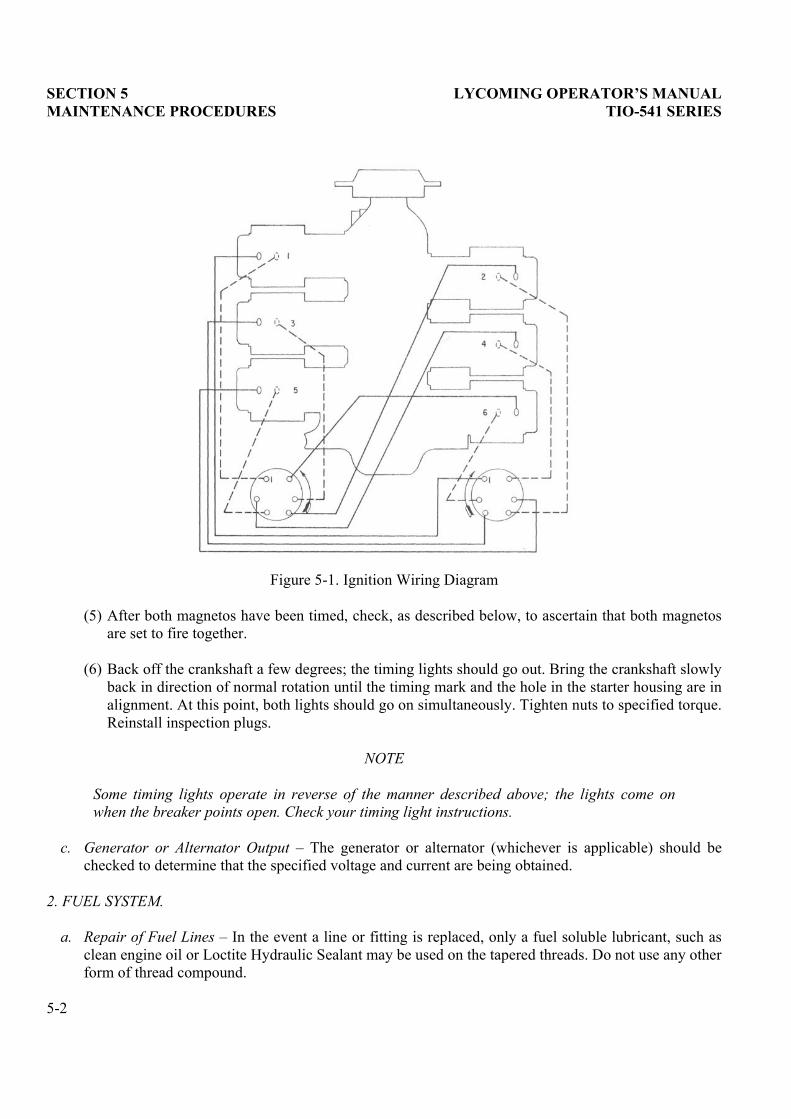
Figure 5-1. Ignition Wiring Diagram
(5) After both magnetos have been timed, check, as described below, to ascertain that both magnetosare set to fire together.
(6) Back off the crankshaft a few degrees; the timing lights should go out. Bring the crankshaft slowlyback in direction of normal rotation until the timing mark and the hole in the starter housing are inalignment. At this point, both lights should go on simultaneously. Tighten nuts to specified torque.Reinstall inspection plugs.
NOTE
Some timing lights operate in reverse of the manner described above; the lights come onwhen the breaker points open. Check your timing light instructions.
c. Generator or Alternator Output � The generator or alternator (whichever is applicable) should bechecked to determine that the specified voltage and current are being obtained.
2. FUEL SYSTEM.
a. Repair of Fuel Lines � In the event a line or fitting is replaced, only a fuel soluble lubricant, such asclean engine oil or Loctite Hydraulic Sealant may be used on the tapered threads. Do not use any otherform of thread compound.
5-2

LYCOMING OPERATOR�S MANUAL SECTION 5 TIO-541 SERIES MAINTENANCE PROCEDURES
b. Fuel Injector Inlet Screen Assembly � Remove the assembly and check the screen for distortion oropenings in the strainer. Install a new screen if either of these conditions exists. Clean screen assemblyin solvent and dry with compressed air. To install the screen assembly, place the gasket on the screenassembly and install the assembly in the throttle body and tighten to 65-70 in.-lbs. torque.
c. Fuel Grades and Limitations � Aviation grade fuel 100/130 octane minimum is the specified fuel forthese engines. In the event that the specified fuel is not available at some locations, it is permissible touse higher octane fuel. Fuel of a lower octane than specified is not to be used. Under no circumstancesshould automotive fuel be used (regardless of octane rating).
NOTE
It is recommended that personnel be familiar with the latest revision of Service InstructionNo. 1070 regarding specified fuel for Lycoming engines.
d. Air Intake Ducts and Filter � Check all air intake ducts for dirt or restrictions. Inspect and service airfilters as instructed in the airframe manufacturer�s handbook.
e. Idle Speed and Mixture Adjustment �
(1) Start the engine and warm up in the usual manner until oil and cylinder head temperatures arenormal.
(2) Check magnetos. If the �mag-drop� is normal, proceed with idle adjustment.
(3) Close throttle so that the engine idles at the airframe manufacturer�s recommended idling RPM. If the RPM changes appreciably after making idle mixture adjustment during the succeeding steps,readjust the idle speed to the desired RPM.
NOTE
The idle mixture must be adjusted with the fuel boost pump �ON�.
(4) When the idling speed has stabilized, move the cockpit mixture control lever with a smooth,steady pull toward the Idle Cut-Off position and observe the tachometer for any change during theleaning process. Caution must be exercised to return the mixture control to �Full Rich� position before the RPM can drop to a point where the engine cuts out. An increase of more than 50 RPMwhile �leaning out� indicates an excessively rich idle mixture An immediate decrease in RPM (ifnot preceded by a momentary increase) indicates that the idle mixture is too lean.
If the above indicates that the idle adjustment is too rich or too lean, turn the idle mixtureadjustment in the direction required for correction, and check this new position by repeating theabove procedure. Make additional adjustments as necessary until a check results in a momentarypick-up of approximately 50 RPM. Each time the adjustment is changed, the engine should be runup to 2000 RPM to clear the engine before proceeding with the RPM check. Make finaladjustment of the idle speed adjustment to obtain the desired idling RPM with closed throttle. Theabove method aims at a setting that will obtain maximum RPM with minimum manifold pressure.In case the setting does not remain stable, check the idle linkage; any looseness in this linkagewould cause erratic idling. In all cases, allowance should be made for the effect of weatherconditions and field altitude upon idling adjustment.
5-3

SECTION 5 LYCOMING OPERATOR�S MANUAL MAINTENANCE PROCEDURES TIO-541 SERIES
3. LUBRICATION SYSTEM.
a. Oil Grades and Limitations � Service the engine in accordance with the recommendations shown inSection 3.
NOTE
TIO-541-E series engines must be operated with ashless dispersant lubrication oil asdescribed in latest revision of Service Bulletin No. 318.
b. The adjustable oil relief valve, located at the right rear side of the engine below the oil filter, enablesthe operator to maintain the oil pressure within specified limits. If the pressure under normal operatingconditions should consistently exceed the maximum or minimum specified limits, adjust the valve asfollows:
With the engine warmed up and running at approximately 2000 RPM, observe the reading on the oilpressure gage. If the pressure is above maximum or below minimum specified limits, stop the engineand screw the adjusting screw in to increase pressure or out to decrease pressure. The adjusting screwmay be turned with either a screw driver or a box wrench.
4. CYLINDERS.
a. Removal of Cylinder Assembly �
(1) Remove exhaust manifold.
(2) Remove intake pipe, fuel drain lines, baffle and any clips that might interfere with the cylinderremoval.
(3) Disconnect ignition cable at spark plugs and remove spark plugs.
(4) Remove rocker box cover and rotate crankshaft until piston is approximately at top center of thecompression stroke. This approximate position may be located by observing top of piston throughthe spark plug hole and by watching the valve action.
(5) Pull rocker shafts into cylinder head far enough to remove valve rockers and washers. Removevalve stem cap from exhaust valve. Valve rocker shafts can be removed when cylinder is removedfrom the engine.
(6) Remove push rods by grasping ball end and pulling out of shroud tube. Remove shroud tube bygrasping tube and turning 90° either way. This releases detent on tube from spring. Remove thetubes by first releasing them from the seal seat in the cylinder head and then withdrawing tubesfrom shroud tube adapter on crankcase. Remove shroud tube seal sleeves and seals from outer endof tubes, also remove seals from adapter. Discard all seals. Place washers, springs, and seal sleevesin proper compartment of cleaning basket.
NOTE
The hydraulic lifters, push rods, rocker arms, and valves must be assembled in the samelocation from which they were removed.
5-4

LYCOMING OPERATOR�S MANUAL SECTION 5 TIO-541 SERIES MAINTENANCE PROCEDURES
(7) Remove cylinder base hold-down nuts; then remove cylinder by pulling directly away from thecrankcase. Be careful not to allow the piston to drop against the crankcase as the piston leaves thecylinder.
(8) Use the old cylinder base oil seal ring and crisscross over cylinder base studs and aroundconnecting rod to prevent rod from striking crankcase.
NOTE
In the event that a spark plug Heli-coil must be replaced, it must be replaced with a .010oversize Heli-coil.
b. Removal of Valves and Valve Springs from Cylinder �
(1) Place cylinder over a block of wood to hold the valves in a closed position.
(2) Compress valve springs, using a valve spring compressor.
(3) Remove tapered split keys from the end of valve stems. The valve springs and valve spring seatsmay now be removed from cylinder head.
(4) Hold valve stems so that valves will not fall out. Remove cylinder from holding block.
(5) Remove valves from the inside of the cylinder.
c. Removal of Piston from Connecting Rod � Insert the piston pin puller tube through the piston pin.Assemble the puller nut and proceed to remove the piston pin.
d. Removal, Disassemble, Cleaning, Inspection and Reassembly of Hydraulic Lifters �
(1) Remove capscrews that secure shroud tube adapter over the lifter.
(2) Remove adapter gasket. Lifter can be withdrawn by fingers.
(3) Being careful not to scratch socket, insert a screw driver into lifter and push. This will force thetrapped oil out of the vent hole and release the pressure on the circlip.
(4) Remove and discard the circlip.
CAUTION
UPON RELEASE, CIRCLIP MAY SPRING UP WITH GREAT FORCE. BE CAREFUL!
(5) Remove the spring, plunger and socket from the lifter and clean the parts and the lifter body insolvent. Inspect the lifter body for the following imperfections.
Spalling � If the face of the lifter shows small nicks or indentations near the center of the face, it isconsidered pitted or spalled. The pitting will constitute small irregular holes, not to be confusedwith Rockwell hardness check marks, which are round and even. The area covered by spalling willvary with different lifters, but regardless of the degree, the lifter must be replaced.
5-5

SECTION 5 LYCOMING OPERATOR�S MANUAL MAINTENANCE PROCEDURES TIO-541 SERIES
Scoring � The lifter face is scored when small scratch-like lines are found on the surface. Thesemarks are usually found near the outer edge of the face and will appear to radiate from the center.Other scoring marks may be present and extend to the center of the lifter face. Any lifter, with thiscondition in evidence, must be replaced.
Face Wear � The operation of the lifter provides that the lifter rotates during wiping operation ofthe cam. This will form a groove, or path. This path will extend all the way across the face anddeeper penetrations will be noted at the center of the face. If the wear is excessive, it will benoticeable to the touch if the fingernail is rubbed across the lifter face. This condition requiresreplacement of the lifter body.
(6) Reassemble the spring, plunger and socket into the body and secure with a new circlip.
NOTE
The lifter must be perfectly dry to obtain proper dry tappet clearance.
(7) Install the lifter assembly in its position in the crankcase. Install a new shroud tube adapter gasketand secure the shroud tube adapter with capscrews.
e. Assembly of Valves in Cylinder �
(1) Prelubricate valve stems and interior of valve guides with Molytex Grease O or equivalent andinsert each valve stem in its respective guide.
(2) Place cylinder over a wood block so that the valves are held against the seats and assemble thelower spring seat, auxiliary valve spring and outer valve spring over the valve stem and guide.Place the upper spring seat on top of the springs.
NOTE
Place dampener end of spring (close-wound coils marked with dye or lacquer) toward thecylinder.
(3) Using a valve spring compressor, compress the valve springs and place the split keys in the groovearound the upper end of the valve stem. Slowly release the pressure on the valve springcompressor and allow the upper spring seat to lock itself in place around the valve keys.
f. Assembly of Cylinder and Related Parts �
(1) Rotate crankshaft so that the connecting rod of the cylinder being assembled is at top centerposition with both tappets on the low side of the cam in a position that corresponds with bothvalves closed.
(2) Assemble piston with rings so that the cylinder number stamped on the piston pin boss is towardthe front of the engine. The piston pin should be a hand push fit. During assembly always use agenerous quantity of oil, both in the piston pin hole and on the piston pin.
5-6

LYCOMING OPERATOR�S MANUAL SECTION 5 TIO-541 SERIES MAINTENANCE PROCEDURES
(3) Assemble a piston pin plug at each end of the piston pin and place a new rubber oil seal ringaround the cylinder skirt. Coat piston and rings and the inside of the cylinder generously with oil.
NOTE
Before installing cylinder hold-down nuts, lubricate crankcase thru-stud threads with anyone of the following lubricants, or combination of lubricants.1. 90% SAE 50W engine oil and 10% STP.2. Parker Thread Lube.3. 60% SAE 30 engine oil and 40% Parker Thread Lube.
(4) Using a piston ring compressor, assemble the cylinder over the piston with the intake port at thetop and the exhaust port on the bottom.
(5) Push the cylinder all the way on, catching the ring compressor as it is pushed off, and installapplicable cylinder base hold-down nuts. Tighten hold-down nuts to specified torque in themanner described in the following paragraphs.
NOTE
The front two ½ inch thru-studs on each cylinder pad are not secured by screw threads.Therefore, torque must be applied at both ends simultaneously. At any time a cylinder isreplaced, it is necessary to retorque the cylinder base nuts on the opposite cylinder.
(6) Tighten the ½ inch cylinder base nuts to 300 in.-lbs., starting at top left and proceedingcounterclockwise.
(7) Repeat the tightening sequence and tighten all ½ inch nuts to 600 in.-lbs. torque. Be certain allnuts are tightened in the sequence stated.
(8) Tighten the 3/8 inch nuts to 300 in.-lbs. toque. Sequence is optional.
(9) During the final tightening procedure, bearing crush or crankcase shift may have occurred,relieving the load on certain ½ inch nuts. Therefore, as a final check, repeat step (7) above todetermine if all ½ inch cylinder base nuts are tightened to 600 in.-lbs. Hold torque wrench on each½ inch nut for about 5 seconds. If the nut does not turn, it is presumed to be tightened to theproper torque.
CAUTION
AFTER INSTALLATION OF CYLINDER IS COMPLETED, REMOVE ANY NICKS IN THECYLINDER FINS BY FILING OR BURRING.
(10) Assemble new shroud tube oil seals in the shroud tube adapter on the crankcase and on outer endof the push rod shroud tubes; then assemble a shroud tube seal sleeve over each of the outer seals,centering the sleeve on the seal.
5-7

SECTION 5 LYCOMING OPERATOR�S MANUAL TIO-541 SERIES MAINTENANCE PROCEDURES
(11) Assemble shroud tube spring over inner ends of the shroud tubes so that the detent notches areapproximately 90° removed from detents on the tubes. Use shroud tube washers (maximum oftwo) to bring minimum overlap between the spring and detent lugs to 1/8 inch and insert tube endsthrough oil seals in the adapter. Hold both push rod shroud tubes with detent at inner end atunlocked position and insert the outer ends of tubes in holes in cylinder head rocker box. See thatall seals are inserted squarely, and turn each shroud tube 90° thus locking the tubes by engagingthe detents with the notches in the spring. Select the proper push rods, dip ball ends inpreservative oil and insert full length through shroud tubes.
(12) Assemble cap on end of exhaust valve stem and assemble each rocker in its respective positionbetween the bosses; insert the thrust washer between the rocker and inner box and slide valverocker shaft in place to retain the rocker.
(13) Be sure that the piston is at top center of compression stroke and that both valves are closed.Check clearance between the valve stem tip and valve rocker. In order to check this clearance,place the thumb of one hand on the valve rocker directly over the end of the push rod and pushdown so as to compress the hydraulic lifter spring. While holding the spring compressed, checkclearance with feeler gage; the clearance should be between 0.040 and 0.105 inch. If clearancedoes not come within these limits, remove the push rod and insert a longer or shorter push rod asrequired to correct clearance.
NOTE
Inserting a longer push rod will decrease valve clearance.
(14) Install rocker box covers, inter-cylinder baffles, spark plugs, intake pipes, ignition cables, fueldrain lines, exhaust manifold, plus any clips that may have been removed at disassembly.
5. TURBOCHARGER EXHAUST BYPASS VALVE SETTINGS. The butterfly valve in the exhaust bypassvalve is set to a predetermined open and closed clearance. The open and closed positions and directions onhow to set them are called out in Figures 5-2 and 5-3.
6. SETTING FUEL INJECTOR AND CONTROLLER LINKAGE.
The fuel injector and controller linkage must be set as described below to provide the proper amount ofturbocharging and fuel metering to the engine.
a. Remove no. 2 and 4 intake pipes on TIO-541 engines and necessary baffling. Cover intake ports toprevent foreign objects from falling into cylinder. Disconnect aircraft throttle cable from cross shaftcontrol lever. Remove injector connecting rod from both the cross shaft control lever and the throttlelever.
NOTE
In order to insure proper settings, all washers and spacers must be installed properly asspecified in Figure 5-10.
5-8

LYCOMING OPERATOR�S MANUAL SECTION 5 TIO-541 SERIES MAINTENANCE PROCEDURES
Figure 5-2. Open and Closed Position of Exhaust Bypass Valve � TIO-541-A1A, -E1A5, -E1B4
Figure 5-3. Open and Closed Position of Exhaust Bypass Valve � TIO-541-E1C4, -E1D4
5-9

SECTION 5 LYCOMING OPERATOR�S MANUAL MAINTENANCE PROCEDURES TIO-541 SERIES
b. Position the cross shaft control lever using fixture ST-319 thus: Mount the fixture over no. 4 cylinderhold-down 3/8 inch studs and nuts. Secure with two (P/N 383-B) nuts. If unable to secure with nutsbecause of insufficient thread, hold the fixture by hand. The fixture in position is shown in Figure 5-4.
c. Back off idle stop adjusting screw until it just touches the injector stop pin when the throttle butterflyis fully closed. Check clearance with a piece of shim stock or a .0015-inch feeler gage. See Figure 5-5.
d. Place gage (ST-318) over injector stop pin with side marked �.040� down and between pin and end of idle stop adjusting screw. Do not turn from full closed setting at this time. See Figure 5-6.
e. Align hole in ball end of injector connecting rod; hole in cross shaft control lever and hole in fixture.Insert fixture pin through all three holes. See Figure 5-4. With throttle lever held firmly against gageon injector, adjust the connecting rod length (maintaining approximately equal thread engagements onboth ends) and attach to throttle lever. Remove fixture (ST-319) and attach injector connecting rod tothe cross shaft control lever using hardware shown in Figure 5-10. Remove gage (ST-318).
f. Replace gage (ST-318) on injector stop pin with the side marked �.025� up. This is the desired clearance between the pad of the throttle arm and the injector stop pin with the throttle lever in fullopen position. Move cross shaft control lever forward to put injector throttle lever in full open positionand maintain a constant pressure between the throttle arm pad and the gage while completing thefollowing step. See Figure 5-7.
g. Remove the controller connecting rod at the controller end. Push the controller arm against the fullboost stop pin (forward). See Figure 5-8. With the controller arm in this position and the throttle leverin the position obtained in the preceding step, adjust the controller connecting rod (maintainingapproximately equal thread engagement on both ends) to match hole locations in both the controllerarm and the connecting rod. Attach the connecting rod to the controller arm and remove the gage fromthe injector stop pin. See Figure 5-9.
h. Check to make certain that all connecting rods are installed with the proper hardware (see Figure 5-10); jam nuts and linkage nuts are tight, and safety the linkage nuts with cotter pins.
i. Reset the idle stop adjusting screw until correct idle is obtained. If throttle lever on the aircraft consoleis misaligned, adjustment may be made either at the ball end of the aircraft throttle cable or by movingthe bracket which holds the throttle cable to the engine. Attach aircraft throttle cable to top hole of thecross shaft control lever.
5-10

LYCOMING OPERATOR�S MANUAL SECTION 5 TIO-541 SERIES MAINTENANCE PROCEDURES
Figure 5-4. Fixture ST-319 Installed and Showing Cross ShaftControl Level in Closed Throttle Position
Figure 5-5. Setting Idle Adjusting Screw at Injector Stop Pin
5-11

SECTION 5 LYCOMING OPERATOR�S MANUAL MAINTENANCE PROCEDURES TIO-541 SERIES
Figure 5-6. Obtaining Clearance of Throttle Lever in Closed Position
Figure 5-7. Obtaining Clearance of Throttle Lever in Full Open Position
5-12

LYCOMING OPERATOR�S MANUAL SECTION 5 TIO-541 SERIES MAINTENANCE PROCEDURES
Figure 5-8. View Showing Controller Arm in Full Boost Position
Figure 5-9. View Showing Controller Connecting Rod SecuredTo Controller Arm in Full Boost Position
5-13

SECTION 5 LYCOMING OPERATOR�S MANUAL MAINTENANCE PROCEDURES TIO-541 SERIES
Figure 5-10. Fuel Injector and Controller Rods Attaching Parts
5-14

LYCOMING OPERATOR�S MANUAL
SECTION 6TROUBLE-SHOOTING � ENGINE
Page
Failure of Engine to Start............................................................................................................................ 6-1
Failure of Engine to Idle Properly.............................................................................................................. 6-1
Low Power and Uneven Running............................................................................................................... 6-2
Failure of Engine to Develop Full Power................................................................................................... 6-2
Rough Engine ............................................................................................................................................... 6-2
Low Oil Pressure.......................................................................................................................................... 6-3
High Oil Temperature ................................................................................................................................. 6-3
Excessive Oil Consumption......................................................................................................................... 6-3
TROUBLE-SHOOTING � TURBOCHARGER
Excessive Noise or Vibration....................................................................................................................... 6-4
Engine Will Not Deliver Rated Power ....................................................................................................... 6-4
Critical Altitude Lower Than Specified..................................................................................................... 6-5
Engine Surges or Smokes ............................................................................................................................ 6-5
High Deck Pressure (Compressor Discharge Pressure) ........................................................................... 6-5

This Page Intentionally Left Blank.

LYCOMING OPERATOR�S MANUAL SECTION 6 TIO-541 SERIES TROUBLE-SHOOTING
SECTION 6
TROUBLE-SHOOTING
Experience has proven that the best method of trouble-shooting is to decide on the various possible causesof a given trouble and then to eliminate causes one by one, beginning with the most probable. The followingcharts list some of the more common troubles which may be encountered in maintaining aircraft engines andturbochargers; their probable causes and remedies.
1. TROUBLE-SHOOTING � ENGINE.
TROUBLE PROBABLE CAUSE REMEDY
Failure of Engine to Start Lack of fuel. Check fuel system for leaks. Fillfuel tank. Clean dirty lines,strainers, or fuel valves.
Overpriming. Unload engine by standardclearing procedure.
Incorrect throttle setting. Open throttle to ¼ of its range.
Defective spark plugs. Clean and adjust or replace sparkplugs.
Defective ignition wire. Check with tester and replace anydefective wires.
Improper operation of magneto. Clean points. Check timing.
Internal failure. Check oil screens for metalparticles. If found, completeoverhaul of engine is indicated.
Failure of Engine to Idle Properly Incorrect idle mixture. Adjust mixture control.
Incorrect idle speed. Adjust idle speed.
Leak in induction system. Tighten all connections andreplace any defective parts.
Uneven cylinder compression. Check condition of piston ringsand valve seats.
Faulty ignition system. Check ignition system.
6-1

SECTION 6 LYCOMING OPERATOR�S MANUAL TROUBLE-SHOOTING TIO-541 SERIES
TROUBLE PROBABLE CAUSE REMEDY
Low Power and Uneven Running Mixture too rich; indicated bysluggish engine, red exhaustflame. Extreme cases indicated byblack smoke at exhaust.
Readjustment of fuel injector isindicated.
Mixture too lean; indicated byoverheating and back firing.
Check fuel lines for restrictions.Readjust mixture.
Leak in induction system. Tighten all connections, replaceany defective parts.
Defective spark plugs. Clean and gap or replace sparkplugs.
Improper fuel. Fill tank with fuel ofrecommended grade.
Magneto breaker points notworking properly.
Clean points, check timing.
Defective ignition wire. Check wires with tester, replaceany defective wires.
Defective spark plug terminalconnectors.
Check and replace connectors ifnecessary.
Failure of Engine to Develop FullPower
Leak in induction system. Tighten all connections, replaceany defective parts.
Throttle lever out of adjustment. Check travel of throttle linkage.
Improper fuel flow. Check strainers and flow at fuelinjector.
Restriction in air scoop. Examine air scoop and removeany obstructions.
Improper fuel. Drain and refill tank with fuel ofrecommended grade.
Faulty ignition. Check ignition system.
Rough Engine Cracked engine mount. Replace or repair mount.
Defective mounting busing. Replace bushing.
Uneven compression. Check condition of piston ringsand valve seats.
6-2

LYCOMING OPERATOR�S MANUAL SECTION 6 TIO-541 SERIES TROUBLE-SHOOTING
TROUBLE PROBABLE CAUSE REMEDY
Low Oil Pressure Insufficient oil. Fill sump with oil.
Air lock or dirt in relief valve. Remove and clean oil pressurerelief valve.
Dirty oil strainers. Remove and clean oil strainers.
High oil temperatures. See �High Oil Temperatures� in �Trouble� column.
Defective pressure gage. Replace gage.
Stoppage in oil pump intakepassage.
Check line for obstruction.
High Oil Temperature Insufficient oil supply. Fill sump with oil ofrecommended grade.
Low grade of oil. Drain and fill sump with oilconforming to specifications.
Clogged oil lines or strainers. Clean oil lines and strainers.
Excessive blow-by. Usually caused by worn or struckrings.
Failed or failing bearings. Examine oil strainers for metalparticles. If found, overhaul ofengine is indicated.
Defective temperature gage. Replace gage.
Excessive Oil Consumption Low grade of oil. Fill sump with oil conforming tospecifications.
Failing or failed bearings. Examine oil strainers for metalparticles. If found, overhaul ofengine is indicated.
Worn piston rings. Install new rings.
Incorrect installation of pistonrings.
Install new rings.
Failure of rings to seat (newnitrided barrels).
Climb to cruise altitude at fullpower and operate at 75% cruisepower setting until consumptionstabilizes.
6-3

SECTION 6 LYCOMING OPERATOR�S MANUAL TROUBLE-SHOOTING TIO-541 SERIES
2. TROUBLE-SHOOTING � TURBOCHARGER
TROUBLE PROBABLE CAUSE REMEDY
Excessive Noise or Vibration Improper bearing lubrication. Supply required oil pressure.Clean or replace oil line. If troublecontinues, overhaul turbocharger.
Leak in engine intake or exhaustmanifold.
Tighten loose connections, orreplace manifold gaskets asnecessary.
Engine Will Not Deliver RatedPower
Clogged manifold system. Clean all ducting.
Foreign material lodged incompressor impeller or turbine.
Disassemble and clean.
Excessive dirt build-up incompressor.
Thoroughly clean compressorassembly. Service air cleaner andcheck for leakage.
Leak in engine intake or exhaustmanifold.
Tighten loose connections, orreplace manifold gaskets asnecessary.
Rotating assembly bearingseizure.
Overhaul turbocharger.
Restriction in return lines fromexhaust bypass valve to variablepressure controller.
Remove and clean lines.
Variable pressure controller out ofadjustment.
Adjust variable pressurecontroller.
Oil pressure too low. Tighten fittings, replace lines orhoses. Increase oil pressure.
Oil inlet to exhaust bypass valveclogged.
Remove oil line at inlet and cleanorifice.
Variable pressure controllermalfunction.
Adjust controller. Install newcontroller if needed.
Exhaust bypass valve not closingbecause of low oil pressure orbutterfly shaft binding.
Check for oil pressure difficulty.Examine shaft for evidence ofbinding.
6-4

LYCOMING OPERATOR�S MANUAL SECTION 6 TIO-541 SERIES TROUBLE-SHOOTING
TROUBLE PROBABLE CAUSE REMEDY
Engine Will Not Deliver RatedPower (Cont.)
Impeller binding, frozen orfouling housing.
Check bearings for evidence offailure. Overhaul turbocharger.
Piston seal in exhaust bypassvalve actuator leaking.
Replace piston seal.
Critical Altitude Lower ThanSpecified
Controller not getting enough oilpressure to close bypass valve.
Check pump outlet pressure, oilfilters and lines for leaks orobstructions.
Chips under metering valve incontroller holding it open.
Replace controller.
Metering jet in exhaust bypassvalve actuator plugged.
Remove exhaust bypass valveactuator and clean jet.
Exhaust bypass valve actuatorpiston seal leaking excessively.
Clean cylinder and replace pistonseal.
Exhaust bypass valve sticking. Clean and free action.
Engine Surges or Smokes Air in oil lines or exhaust bypassvalve actuator.
Bleed system.
Controller metering valve stemseal leaking oil into manifold.
Replace controller.
Exhaust bypass valve actuator tobypass valve linkage binding.
Correct cause of binding.
Clogged breather. Check breather for restriction toair flow.
NOTE
Smoke would be normal if engine has idled for a prolonged period.
High Deck Pressure (CompressorDischarge Pressure)
Controller metering valve notopening.
Replace controller.
Exhaust bypass valve stickingclosed.
Shut off valve in return lineinoperative.
Controller return line restricted. Clean or replace line.
Oil pressure too high. Reduce oil pressure.
Exhaust bypass valve actuatorpiston locked in closed position.
Disassemble actuator, checkcondition of piston and packing.
Variable pressure controllermalfunction.
Replace controller.
6-5

This Page Intentionally Left Blank.

LYCOMING OPERATOR�S MANUAL
SECTION 7INSTALLATION AND STORAGE
Page
Unpacking..................................................................................................................................................... 7-1
Preparation of Engine for Installation....................................................................................................... 7-1
Inspection of Engine Mounting .................................................................................................................. 7-2
Attaching Engine to Mounts ....................................................................................................................... 7-2
Engine Accessories ....................................................................................................................................... 7-2
Location of Accessories, Drives, and Oil and Fuel Connections ............................................................. 7-2
Corrosion Prevention in Engines Installed in Inactive Aircraft.............................................................. 7-2

This Page Intentionally Left Blank.

LYCOMING OPERATOR�S MANUAL SECTION 7 TIO-541 SERIES INSTALLATION AND STORAGE
SECTION 7
INSTALLATION AND STORAGE
1. UNPACKING.
General � Lycoming TIO-541 series aircraft engines are securely packed for shipment, one to the crate in ahorizontal position. The attaching parts are packed in a separate carton within the engine crate.
Unpacking � Open shipping crate. Remove inner carton containing loose attaching parts. Attach lifting cableto lifting eyes. With a suitable hoist take up the slack cable. Remove the bolts and lift engine clear ofshipping crate. With the engine in this position, remove the bottom plugs from each cylinder and rotatecrankshaft a few revolutions to drain the oil from the cylinders. Assemble spark plugs and clean the exteriorof the engine thoroughly.
2. PREPARATION OF ENGINE FOR INSTALLATION. Before installing an engine that has been preparedfor storage, remove all dehydrator plugs and preservative oil. Should any of the dehydrator plugs, containingcrystals of silica-gel or similar material, be broken during their term of storage or upon their removal fromthe engine, and if any of the content shall fall into the engine, that portion of the engine must bedisassembled and thoroughly cleaned before using the engine. Preservative oil can be removed by removingthe bottom spark plugs and turning the crankshaft three or four revolutions by hand. The preservative oilwill then drain through the spark plugholes. Draining will be facilitated if the engine is tilted from side toside during the above operation. Preservative oil which has accumulated in the sump can be drained byremoving the oil sump drain plug. Engines that have been stored in a cold place should be removed to anenvironment of at least 70°F (21°C) for a period of 24 hours before preservative oil is drained from thecylinders. If this is not possible, heat the cylinders with heat lamps before attempting to drain the engine.
After the oil sump has been drained, the plug should be replaced, safety-wired, and the sump filled withlubricating oil. The latest revision of Service Instruction No. 1014 contains complete lubricating oilrecommendations. The crankshaft should again be turned several revolutions to saturate the interior of theengine with clean oil. When installing spark plugs, make sure that they are clean; if not, wash them in cleanpetroleum solvent. Of course, there will be a small amount of preservative oil remaining in the engine butnot in sufficient quantity to prove harmful. However, after twenty-five hours of operation, the lubricating oilshould be drained while the engine is hot. This will remove any residual preservative oil that may bepresent.
CAUTION
DO NOT ROTATE THE CRANKSHAFT OF AN ENGINE CONTAINING PRESERVATIVEOIL BEFORE REMOVING THE SPARK PLUGS, BECAUSE IF THE CYLINDERSCONTAIN ANY APPRECIABLE AMOUNT OF THE MIXTURE, THE RESULTINGACTION, KNOWN AS HYDRAULICING, WILL CAUSE DAMAGE TO THE ENGINE.ALSO, ANY CONTACT OF THE PRESERVATIVE OIL WITH PAINTED SURFACESSHOULD BE AVOIDED.
7-1

SECTION 7 LYCOMING OPERATOR�S MANUAL INSTALLATION AND STORAGE TIO-541 SERIES
The oil strainers should be removed and cleaned in gasoline or some other hydrocarbon solvent. The fuelfilter screen located in the fuel inlet of the throttle body should also be removed and cleaned in ahydrocarbon solvent. Inject clean fuel into the fuel inlet with the fuel outlets uncapped until clean fuel flowsfrom the outlets. Do not exceed 15 psi inlet pressure. The operator should also note if any valves aresticking. If they are, this condition can be eliminated by coating the valve stem generously with lubricatingoil.
Inspection of Engine Mounting � If the aircraft is one from which an engine has been removed, make surethat the engine mounts are not bent or damaged by distortion or misalignment. If so, abnormal stresses canbe produced within the engine.
Attaching Engine to Mounts � See aircraft manufacturer�s recommendations for method of mounting engine.
Engine Accessories � Considerable time and effort can be saved if the accessories are assembled on theengine before installation in the airframe.
CORROSION PREVENTION IN ENGINES INSTALLED IN INACTIVE AIRCRAFT
Corrosion can occur, especially in new or overhaul engines, on cylinder walls of engines that will beinoperative for periods as brief as two days. Therefore, the following preservation procedure isrecommended for inactive engines and will be effective in minimizing the corrosion condition for a periodup to thirty days.
NOTE
Ground running the engine for brief periods of time is not a substitute for the followingprocedure; in fact, the practice of ground running will tend to aggravate rather thanminimize the corrosion condition.
a. As soon as possible after the engine is stopped, move the aircraft into the hangar, or other shelterwhere the preservation process if to be performed.
b. Remove sufficient cowling to gain access to the spark plugs and remove both spark plugs from eachcylinder.
c. Spray the interior of each cylinder with approximately two (2) ounces of corrosion preventive oilwhile cranking the engine about five (5) revolutions with the starter. The spray gun nozzle may beplaced in either of the spark plug holes.
NOTE
Spraying should be accomplished using an airless spray gun (Spraying Systems Co.,�Gunjet� Model 24A-8395 or equivalent). In the event an airless spray gun is not available,personnel should install a moisture trap in the air line of a conventional spray gun and becertain oil is hot at the nozzle before spraying cylinders.
d. With the crankshaft stationary, again spray each cylinder through the spark plug holes withapproximately two (2) ounces of corrosion preventive oil. Assemble spark plugs and do not turncrankshaft after cylinders have been sprayed.
7-2

LYCOMING OPERATOR�S MANUAL SECTION 7 TIO-541 SERIES INSTALLATION AND STORAGE
The corrosion preventive oil to be used in the foregoing procedure should conform to specification MIL-L-6529, Type 1, heated to 200°F/220°F (93°C/104°C) spray nozzle temperature. It is not necessary to flushpreservative oil from the cylinder prior to flying the aircraft. The small quantity of oil coating the cylinderswill be expelled from the engine during the first few minutes of operation.
NOTE
Oils of the type mentioned are to be used in Lycoming aircraft engines for corrosionprevention only, and not for lubrication. See the latest revision of Lycoming ServiceInstruction No. 1014 and Service Bulletin No. 318 for recommended lubricating oil.
Figure 7-1. Installation Drawing � Left Side View � TIO-541-A Series
7-3

SECTION 7 LYCOMING OPERATOR�S MANUAL INSTALLATION AND STORAGE TIO-541 SERIES
Figure 7-2. Installation Drawing � Right Side View � TIO-541-A Series
Figure 7-3. Installation Drawing � Left Side View � TIO-541-E Series
7-4

LYCOMING OPERATOR�S MANUAL SECTION 7 TIO-541 SERIES INSTALLATION AND STORAGE
Figure 7-4. Installation Drawing � Right Side View � TIO-541-E Series
7-5

This Page Intentionally Left Blank.

LYCOMING OPERATOR�S MANUAL
SECTION 8TABLES
Page
Ground Run After Top Overhaul .............................................................................................................. 8-2
Flight Test After Top Overhaul.................................................................................................................. 8-3
Table of Speed Equivalents ......................................................................................................................... 8-4
Centigrade-Fahrenheit Conversion Table................................................................................................. 8-5
Inch Fractions Conversions ........................................................................................................................ 8-6

This Page Intentionally Left Blank.

LYCOMING OPERATOR�S MANUAL SECTION 8 TIO-541 SERIES TABLES
SECTION 8
TABLES
FOR TIGHTENING TORQUE RECOMMENDATIONS AND INFORMATION
CONCERNING TOLERANCES AND DIMENSIONS THAT MUST BE MAINTAINED
IN LYCOMING AIRCRAFT ENGINES, CONSULT LATEST REVISION OF SPECIAL
SERVICE PUBLICATION NO. SSP-1776.
CONSULT LATEST REVISION OF LYCOMING SERVICE INSTRUCTION NO. 1029
AND NO. 1150 FOR THE PROPER PROCEDURE FOR TIGHTENING CYLINDER
BASE HOLD DOWN NUTS TO CORRECT TORQUE.
8-1

SECTION 8 LYCOMING OPERATOR�S MANUAL TABLES TIO-541 SERIES
8-2

LYCOMING OPERATOR�S MANUAL SECTION 8 TIO-541 SERIES TABLES
8-3

SECTION 8 LYCOMING OPERATOR�S MANUAL TABLES TIO-541 SERIES
TABLE OF SPEED EQUIVALENTS
Sec./Mi. M.P.H. Sec./Mi. M.P.H. Sec./Mi. M.P.H.
72.065.560.055.451.448.045.042.340.037.936.034.332.731.330.028.8
50556065707580859095100105110115120125
27.726.625.724.824.023.222.521.821.220.620.019.418.918.418.017.6
130135140145150155160165170175180185190195200205
17.116.716.416.015.615.014.413.813.312.812.412.011.611.210.910.6
210215220225230240250260270280290300310320330340
8-4

LYCOMING OPERATOR�S MANUAL SECTION 8 TIO-541 SERIES TABLES
CENTIGRADE-FAHRENHEIT CONVERSION TABLE
Example: To convert 20°C to Fahrenheit, find 20 in the center column headed (F-C); then read 68.0°F inthe column (F) to the right. To convert 20°F to Centigrade; find 20 in the center column and read �6.67°C in the (C) column to the left.
C F-C F C F-C C
-56.7 -70 -94.0 104.44 220 428.0-51.1 -60 -76.0 110.00 230 446.0-45.6 -50 -58.0 115.56 240 464.0-40.0 -40 -40.0 121.11 250 482.0-34.0 -30 -22.0 126.67 260 500.0-28.9 -20 -4.0 132.22 270 518.0-23.3 -10 14.0 137.78 280 536.0-17.8 0 32.0 143.33 290 554.0
-12.22 10 50.0 148.89 300 572.0-6.67 20 68.0 154.44 310 590.0-1.11 30 86.0 160.00 320 608.04.44 40 104.0 165.56 330 626.0
10.00 50 122.0 171.11 340 644.015.56 60 140.0 176.67 350 662.021.11 70 158.0 182.22 360 680.026.67 80 176.0 187.78 370 698.032.22 90 194.0 193.33 380 716.037.78 100 212.0 198.89 390 734.043.33 110 230.0 204.44 400 752.048.89 120 248.0 210.00 410 770.054.44 130 266.0 215.56 420 788.060.00 140 284.0 221.11 430 806.065.56 150 302.0 226.67 440 824.071.00 160 320.0 232.22 450 842.076.67 170 338.0 237.78 460 860.082.22 180 356.0 243.33 470 878.087.78 190 374.0 248.89 480 896.093.33 200 392.0 254.44 490 914.098.89 210 410.0 260.00 500 932.0
8-5

SECTION 8 LYCOMING OPERATOR�S MANUAL TABLES TIO-541 SERIES
INCH FRACTIONS CONVERSIONSDecimals, Area of Circles and Millimeters
Inch Decimal Area MM Inch Decimal Area MMFraction Equiv. Sq. In. Equiv. Fraction Equiv. Sq. In. Equiv.
1/64 .0156 .0002 .397 1/2 .5 .1964 12.7001/32 .0312 .0008 .794 17/32 .5312 .2217 13.494
3/64 .0469 .0017 1.191 35/64 .5469 .2349 13.8911/16 .0625 .0031 1.587 9/16 .5625 .2485 14.288
3/32 .0937 .0069 2.381 19/32 .5937 .2769 15.0817/64 .1094 .0094 2.778 39/64 .6094 .2916 15.478
1/8 .125 .0123 3.175 5/8 .625 .3068 15.8755/32 .1562 .0192 3.969 21/32 .6562 .3382 16.669
11/64 .1719 .0232 4.366 43/64 .6719 .3545 17.0653/16 .1875 .0276 4.762 11/16 .6875 .3712 17.462
7/32 .2187 .0376 5.556 23/32 .7187 .4057 18.25615/64 .2344 .0431 5.593 47/64 .7344 .4235 18.653
1/4 .25 .0491 6.350 3/4 .75 .4418 19.0509/32 .2812 .0621 7.144 25/32 .7812 .4794 19.844
19/64 .2969 .0692 7.540 51/64 .7969 .4986 20.2415/16 .3125 .0767 7.937 13/16 .8125 .5185 20.637
11/32 .3437 .0928 8.731 27/32 .8437 .5591 21.43123/64 .3594 .1014 9.128 55/64 .8594 .5800 21.828
3/8 .375 .1105 9.525 7/8 .875 .6013 22.22513/32 .4062 .1296 10.319 29/32 .9062 .6450 23.019
27/64 .4219 .1398 10.716 59/64 .9219 .6675 23.4167/16 .4375 .1503 11.112 15/16 .9375 .6903 23.812
15/32 .4687 .1725 11.906 31/32 .9687 .7371 24.60631/64 .4844 .1842 12.303 63/64 .9844 .7610 25.003
8-6