timken thrust and plain bearings catalog ** book …
TRANSCRIPT
CYLINDRICAL ROLLER BEARING CATALOGCCCCCCCCCYYYYYYYYYLLLLLLLLLIIIIIIIIINNNNNNNNNDDDDDDDDDRRRRRRRRRIIIIIIIIICCCCCCCCCAAAAAAAAALLLLLLLLL RRRRRRRRROOOOOOOOOLLLLLLLLLLLLLLLLLLEEEEEEEEERRRRRRRRR BBBBBBBBBEEEEEEEEEAAAAAAAAARRRRRRRRRIIIIIIIIINNNNNNNNNGGGGGGGGG CCCCCCCCCAAAAAAAAATTTTTTTTTAAAAAAAAALLLLLLLLLOOOOOOOOOGGGGGGGGGTIMKEN THRUST AND PLAIN BEARINGS CATALOG


•TIMKEN PRODUCTS CATALOG B415
A
AB
Spherical Plain Bearings
FPOFPO
SPHERICAL PLAIN
Overview: Timken’s spherical plain bearings consist of a spherically ground inner ring housed in a mating outer ring without any rolling elements.
• Sizes: 12.7 mm - 600 mm bore (0.5 in. - 23.622 in.).
• Markets: Construction, mining, metals, power generation, oils and gas, aggregate, paper and forest products.
• Applications: Articulation joints, A-frames, cylinders (steering, lift, tilt, dump), struts, traction bars.
• Features: Lubrication grooves and holes, seals to retain lubricant andprevent contamination, special materials available.
• Benefits: Can carry radial and axial loads in a small envelope and canaccommodate moderate misalignment.
FPO

•
Spherical Plain Bearings
Seal Designator:
TT reinforced rubber seals
SS synthetic resin seals
SF spherical plain type (radial inch); single fractured outer ring
SFH spherical plain type (radial inch); single fractured outer ring, wide inner ring
SBB spherical plain type (radial inch); double fractured outer ring
SBT spherical plain angular contact type (radial inch)
FS spherical plain type (radial metric); single fractured outer ring
FSH spherical plain type (radial metric); single fractured outer ring, wide inner ring
One, two, or three digit number.
For inch series, the number indicates the exact bore size in 1/16ths of an inch (e.g., 12 refers to12/16 in. which is a 3/3 4// in. bore).
For metric series, the number indicates the exact outside diameter size (e.g., 62 is 62 mm).
7 SF 12 – SSSF 12
One, two, or three digit “Series” number.
For inch series, the number indicates thenominal bore size (e.g., 10 is 1.00 in.) or an approximate bore size (e.g., 17 is 1.75 in.).
For metric series, the number indicates the exact bore size (e.g., 40 is 40 mm).
B
• B416 TIMKEN PRODUCTS CATALOG

• TIMKEN PRODUCTS CATALOG B417
BSphericalPlain Bearings Page
Introduction . . . . . . . . . . . . . . . . . . . . . . . . . . . . . . . . . . . . . . . B418
General Features . . . . . . . . . . . . . . . . . . . . . . . . . . . . . . . . . . . B418
BEARING TYPES
SF & FS. . . . . . . . . . . . . . . . . . . . . . . . . . . . . . . . . . . . . . . . . . . B418
SF…TT, SF…SS, FS…TT, FS…SS. . . . . . . . . . . . . . . . . . . . . . B418
SBT & SBDT . . . . . . . . . . . . . . . . . . . . . . . . . . . . . . . . . . . . . . . B418
Internal Clearances . . . . . . . . . . . . . . . . . . . . . . . . . . . . . . . . . B419
Load Ratings . . . . . . . . . . . . . . . . . . . . . . . . . . . . . . . . . . . . . . B419
Misalignment. . . . . . . . . . . . . . . . . . . . . . . . . . . . . . . . . . . . . . B420
Housing Design . . . . . . . . . . . . . . . . . . . . . . . . . . . . . . . . . . . . B421
Shaft Design. . . . . . . . . . . . . . . . . . . . . . . . . . . . . . . . . . . . . . . B421
Lubrication (SF, FS, SBT) . . . . . . . . . . . . . . . . . . . . . . . . . . . . B421
Temperature. . . . . . . . . . . . . . . . . . . . . . . . . . . . . . . . . . . . . . . B422
Shaft Fits . . . . . . . . . . . . . . . . . . . . . . . . . . . . . . . . . . . . . . . . . B422
Tolerances . . . . . . . . . . . . . . . . . . . . . . . . . . . . . . . . . . . . . . . . B423
Radial Bearings, Type SF . . . . . . . . . . . . . . . . . . . . . . . . . . . . B424
Radial Bearings, Type FS . . . . . . . . . . . . . . . . . . . . . . . . . . . . B426
Radial Bearings, FSH. . . . . . . . . . . . . . . . . . . . . . . . . . . . . . . . B428
Radial Bearings, Type SFH . . . . . . . . . . . . . . . . . . . . . . . . . . . B430
Angular Contact Bearings, Type SBT . . . . . . . . . . . . . . . . . . B432

• B418 TIMKEN PRODUCTS CATALOG
A
AB
SPHERICAL PLAIN BEARINGS
BEARING TYPESSF & FS
These bearings are designed primarily to carry radial loads and handle moderate misalignment. The outer ring is usually fractured axially in one place, parallel to its axis, to permit assembly of the bearing rings, which do not have loading slots.
These types can also be supplied with double-fractured outer rings (designation SBB) when this feature is desired for easier assembly in an application.
SF…TT, SF…SS, FS…TT, FS…SSThese bearings are dimensionally interchangeable with the SF
and FS Series, and have the same general characteristics. However, they also incorporate lip seals.
The seals are securely retained in the outer ring and will withstand high grease pressures during relubrication. Positive retention of the seals assures full distribution of the lubricant to all bearing surfaces. SF…TT and FS…TT incorporate two reinforced nitrile rubber seals. SF…SS and FS…SS are assembled with synthetic resin seals; Operating temperatures of the seals should not exceed 212° F (100° C).
SBT & SBDTThese bearings are designed for single direction thrust loading
and some misalignment. Inner and outer rings are separable. The raceways are essentially hemispherical, and the rings are designed to provide maximum spherical raceway contact in the axial direction.
The SBDT style is designed for single direction thrust loading while the SBDT style is designed for thrust loading in two directions
SF and FS
SF and FS
The spherical plain bearing has a spherically shaped inner ring with a ground cylindrical bore for shaft mounting. The cylindrical outer surface of the outer ring permits convenient mounting in a housing.
Spherical plain bearings offer the following advantages:• High capacity• Ability to accommodate misalignment • Superior performance in low frequency oscillating
applications• Simplified housing and shaft design• Easy installation• Radial types available with seals
For all types of spherical plain bearings, both the inner and outer rings are manufactured from through-hardened steel and are precision ground.
The dimensional data lists spherical plain bearings successively by larger bore sizes.
Timken also supplies spherical plain bearings made to special designs. These include standard design bearings made with special materials, clearances, and finishes or bearings with special configurations, such as extended inner rings.
INTRODUCTION GENERAL FEATURES METAL ON METAL BEARINGS
Rings are phosphate treated and coated with molybdenum disulfide (MoS2) to minimize friction of contacting surfaces.
These bearings are available as radial types (SF Series and FS Series) and angular contact thrust (SBT Series).
SF and FS Series include lubrication holes and grooves in both inner and the outer rings to permit relubrication through either the shaft or housing.
SBT angular contact bearings have lubricating holes and grooves in the outer ring for relubrication through the housing.
SF and FS Series are available with integral seals as SF…TT, SF…SS, FS…TT and FS…SS, and incorporate lip seals designed to retain lubricant and protect the spherical surfaces from external contamination.
SBT SBDT

• TIMKEN PRODUCTS CATALOG B419
A
AB
Spherical Plain Bearings
INTERNAL CLEARANCESRadial internal clearance is defined as the total possible
movement of the inner ring relative to the outer ring in a radial direction. Axial internal clearance is the total possible movement of the inner relative to the outer ring in an axial direction.
Radial internal clearances listed for the SF and FS Series are for finish ground, unmounted bearings prior to fracture of the outer ring. The molybdenum disulfide coating reduces this clearance by a maximum of .05 mm (.002 in.). The maximum interference fits using suggested housing and shaft dimensions will maintain a satisfactory minimum internal clearance in the mounted condition, accommodating coating thickness, outer ring compression, and inner ring expansion.
LOAD RATINGSDYNAMIC LOAD RATINGS
SF & FSThe dynamic load rating listed in the tables of dimensions is
based on a maximum stress level of 85 megapascals (approximately 12,300 psi) between the sliding contact surfaces. It is the maximum load suggested for bearings subjected to intermittent operation with periodic lubrication.
The dynamic load rating is based on the radially projected area of the inner ring bore under the condition where, with the suggested fitting practice and periodic lubrication, rotation normally takes place.
For intermittent loading and operation, the applied radial load should not exceed the dynamic load rating. For constant loading and continuous operation, the applied radial load should not exceed 75 percent of the dynamic load rating. For dynamic or static thrust loading, use 25 percent of the respective radial load rating value should be used. For combined radial and thrust ratings, consult your Timken representative.
SBTThe dynamic load rating is based on the same stress levels as
SF shown above and is the maximum thrust load suggested for extended life with periodic lubrication. It is based on the axially projected area of the spherical surfaces in contact. Where the shaft shoulder supports high thrust loads, it is suggested that hardened shafts be employed.
EQUIVALENT THRUST LOAD
SBTFor combined radial and thrust loading under intermittent
dynamic conditions, the equivalent thrust load (Te) must not exceed the dynamic load rating. For constant loading and continuous operation, the equivalent load (Te), or the axial load (T) when the radial load (R) is zero, must not exceed 70 percent of the dynamic load rating:
Te = T + 1.4RTe = Equivalent thrust load per bearingT = Applied thrust load and ⁄ or preloadR = Applied radial load per bearing
The limit load rating of all spherical plain bearings listed is the maximum static load that can be applied to the bearing. This load should not be exceeded. The ultimate, or static fracture rating of the bearing is at least 1.5 times the limit load rating.
Shaft and housing stresses should be checked when the applied load approaches the limit load rating since the shaft or housing may then become the critical factor.

• B420 TIMKEN PRODUCTS CATALOG
A
AB
SPHERICAL PLAIN BEARINGS
In many applications, the degree of misalignment of the radial types of spherical plain bearings is determined by the side clearance between the yoke and the bearing housing as illustrated.
When the bearing is mounted without such restrictions, a larger misalignment can be accommodated: is the maximum angle of misalignment for sealed bearings as illustrated. If is exceeded, the seal lips will slide off the spherical surface. Seal effectiveness is then lost and damage to the seal lip will occur if contact is made between the seal lip and shaft shoulder.
Greater misalignment under light to medium loads is possible with unsealed plain radial bearings as shown by angle '. This requires limiting the shaft shoulder diameter to the suggested dimension (da) and also requires sufficient side clearance for the outer ring and housing.
Misalignment greater than ' reduces the load carrying ability of the radial plain spherical bearings. When extreme misalignment is present, the strength of the shaft in shear and bending should be carefully checked, since the shaft support may be some distance away from the bearing.
Type SBT angular contact bearing permits a tilting angle provided the housing shoulder clears the shaft. Such misaligment is limited by the bore of the outer ring touching the through shaft, as shown. A larger angle of misalignment is possible where a stub shaft is used. If the tilting angle exceeds , your Timken representative should be consulted for suggestions.
MISALIGNMENT
'
da
Side clearance between yoke and bearing housing
Maximum tilt Maximum tiltsealed bearing unsealed bearing
Maximum tilt(provided housing shoulder clears shaft)
• TIMKEN PRODUCTS CATALOG B421
A
AB
Spherical Plain Bearings
TABLE 1 – STRESS CONCENTRATION FACTOR
Da/D K Da/D K Da/D K
1.2 1.8 1.8 2.4 3 3.7
1.4 2 2 2.7 4 4.7
1.6 2.2 2.5 3.2 5 5.5
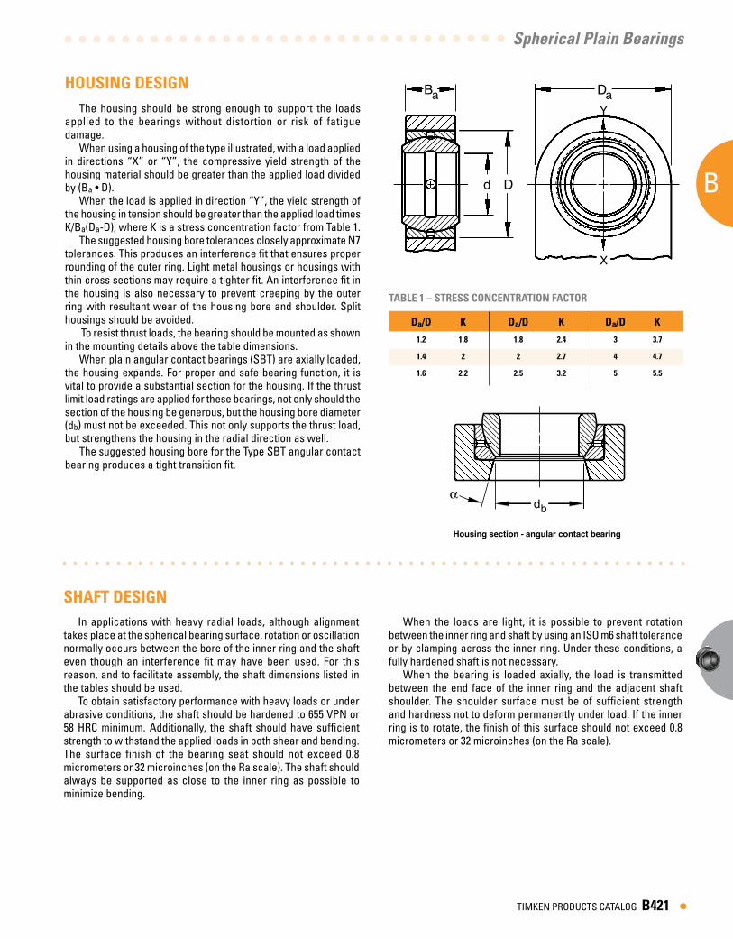
The housing should be strong enough to support the loads applied to the bearings without distortion or risk of fatigue damage.
When using a housing of the type illustrated, with a load applied in directions “X” or “Y”, the compressive yield strength of the housing material should be greater than the applied load divided by (Ba • D).
When the load is applied in direction “Y”, the yield strength of the housing in tension should be greater than the applied load times K/Ba(Da-D), where K is a stress concentration factor from Table 1.
The suggested housing bore tolerances closely approximate N7 tolerances. This produces an interference fit that ensures proper rounding of the outer ring. Light metal housings or housings with thin cross sections may require a tighter fit. An interference fit in the housing is also necessary to prevent creeping by the outer ring with resultant wear of the housing bore and shoulder. Split housings should be avoided.
To resist thrust loads, the bearing should be mounted as shown in the mounting details above the table dimensions.
When plain angular contact bearings (SBT) are axially loaded, the housing expands. For proper and safe bearing function, it is vital to provide a substantial section for the housing. If the thrust limit load ratings are applied for these bearings, not only should the section of the housing be generous, but the housing bore diameter (db) must not be exceeded. This not only supports the thrust load, but strengthens the housing in the radial direction as well.
The suggested housing bore for the Type SBT angular contact bearing produces a tight transition fit.
HOUSING DESIGN
In applications with heavy radial loads, although alignment takes place at the spherical bearing surface, rotation or oscillation normally occurs between the bore of the inner ring and the shaft even though an interference fit may have been used. For this reason, and to facilitate assembly, the shaft dimensions listed in the tables should be used.
To obtain satisfactory performance with heavy loads or under abrasive conditions, the shaft should be hardened to 655 VPN or 58 HRC minimum. Additionally, the shaft should have sufficient strength to withstand the applied loads in both shear and bending. The surface finish of the bearing seat should not exceed 0.8 micrometers or 32 microinches (on the Ra scale). The shaft should always be supported as close to the inner ring as possible to minimize bending.
SHAFT DESIGNWhen the loads are light, it is possible to prevent rotation
between the inner ring and shaft by using an ISO m6 shaft tolerance or by clamping across the inner ring. Under these conditions, a fully hardened shaft is not necessary.
When the bearing is loaded axially, the load is transmitted between the end face of the inner ring and the adjacent shaft shoulder. The shoulder surface must be of sufficient strength and hardness not to deform permanently under load. If the inner ring is to rotate, the finish of this surface should not exceed 0.8 micrometers or 32 microinches (on the Ra scale).
Ba
d D
Da
X
Y
db
Housing section - angular contact bearing

• B422 TIMKEN PRODUCTS CATALOG
A
AB
SPHERICAL PLAIN BEARINGS
SHAFT FITS• The shaft diameters listed in the dimension tables show the
suggested fits for normal service.• The table below is to be used only for applications where
a shaft interference fit is required. Consult your Timken representative for suggestions.
The dry film lubricant (MoS2) is sufficient for static applications and for relatively short periods of dynamic operation.
The bonds between the rings and MoS2 coating may be destroyed by any fluid including oils, greases and water. Any abrasive material present on the dynamic bearing surfaces will ruin the MoS2 coating. If the bearing is subjected to such operating or environmental conditions, it is necessary to relubricate frequently.
The radial bearings, both with and without seals, have lubricating holes and grooves in both the inner and outer rings, permitting relubrication through either the shaft or the housing.
The angular contact bearings have lubricating holes and grooves in the outer ring for relubrication through the bearing housing. The lubrication grooves in the spherical bore of the outer ring traverse a pattern designed to provide effective lubrication. These grooves extend into the small bore of the ring, permitting relubrication through the end of the housing as illustrated.
LUBRICATION (SF, FS, SBT)
TEMPERATURESpherical plain bearings without seals will operate satisfactorily
up to temperatures of 392° F (200° C). For operation at greater temperatures, special materials and lubricants will be required. Operating temperatures for sealed bearings should not exceed 212° F (100° C).
(SF, SFH, FS, FSH, SBT) BEARINGS,Shaft Diameter Tolerance for Interference Fit for Inch and Metric Series
Bore Diameter, d Shaft Tolerance m6
mm inch mm inch
over incl. over incl. high low high low
10 18 0.3937 0.7087 +0.018 +0.007 +0.0007 +0.000318 30 0.7087 1.1811 +0.021 +0.008 +0.0008 +0.000330 50 1.1811 1.9685 +0.025 +0.009 +0.0010 +0.000450 80 1.9685 3.1496 +0.030 +0.011 +0.0012 +0.000580 120 3.1496 4.7244 +0.035 +0.013 +0.0014 +0.0005
120 180 4.7244 7.0866 +0.040 +0.015 +0.0016 +0.0006180 250 7.0866 9.8425 +0.046 +0.017 +0.0018 +0.0007
SBT – Relubricatable mounting
The relubrication cycle will depend on the magnitude of the load, frequency and amplitude of oscillation, environmental conditions and the effectiveness of the sealing used to exclude foreign materials from the bearing surfaces.
If bearings are relubricated, the dynamic load rating depends on the film strength of the added lubricant. High quality EP greases are suggested for best results.

• TIMKEN PRODUCTS CATALOG B423
A
AB
Spherical Plain Bearings
TABLE 3 INNER RING (SF, SFH, SBT, SBDT) BEARINGS, INCH SERIES
Bore Diameter, d Single Mean Width, B1 Bore Diameter, dmp(1)
mm inch mm inch mm in.
over incl. over incl. high low high low high low high low
11.112 50.800 0.4375 2.0000 +0 -0.013 +0 -0.0005 +0 -0.13 +0 -0.00550.800 76.200 2.0000 3.0000 +0 -0.015 +0 -0.0006 +0 -0.13 +0 -0.00576.200 120.650 3.0000 4.7500 +0 -0.020 +0 -0.0008 +0 -0.13 +0 -0.005
120.6500 152.400 4.7500 6.0000 +0 -0.025 +0 -0.0010 +0 -0.13 +0 -0.005
(1) “Single Mean Diameter” is defined as the mean diameter in a single radial plane.
TOLERANCES• Tolerances on pages B412-B420 list the nominal bearing
dimensions.• Tolerances for these dimensions are listed in Tables 1 through
4. They are expressed as variances from nominal.
TABLE 4 OUTER RING (SF, SFH, SBT, SBDT) BEARINGS, INCH SERIES
Outside Diameter, D Single Mean Width, B Outside Diameter, Dmp(2)
mm inch mm inch mm in.
over incl. over incl. high low high low high low high low
20.638 50.800 0.8125 2.0000 +0 -0.013 +0 -0.0005 +0 -0.13 0 -0.00550.800 80.962 2.0000 3.1875 +0 -0.015 +0 -0.0006 +0 -0.13 0 -0.00580.962 120.650 3.1875 4.7500 +0 -0.020 +0 -0.0008 +0 -0.13 0 -0.005
120.650 177.800 4.7500 7.0000 +0 -0.025 +0 -0.0010 +0 -0.13 0 -0.005177.800 222.250 7.0000 8.7500 +0 -0.030 +0 -0.0012 +0 -0.13 0 -0.005
(2) Tolerances apply before coating with MoS2 and fracturing outer ring. “Single Mean Diameter” is defined as the mean diameter in a single radial plane.
TABLE 1 INNER RING (FS, FSH) BEARINGS, METRIC SERIES
Bore Diameter, d Single Mean Width, B1 Bore Diameter, dmp(1)
mm inch mm inch mm in.
over incl. over incl. high low high low high low high low
10 18 0.3937 0.7087 +0 -0.008 +0 -0.0003 +0 -0.12 +0 -0.00518 30 0.7087 1.1811 +0 -0.010 +0 -0.0004 +0 -0.12 +0 -0.00530 50 1.1811 1.9685 +0 -0.012 +0 -0.0005 +0 -0.12 +0 -0.00550 80 1.9685 3.1496 +0 -0.015 +0 -0.0006 +0 -0.15 +0 -0.00680 120 3.1496 4.7244 +0 -0.020 +0 -0.0008 +0 -0.20 +0 -0.008
120 180 4.7244 7.0866 +0 -0.025 +0 -0.0010 +0 -0.25 +0 -0.010180 250 7.0866 9.8425 +0 -0.030 +0 -0.0012 +0 -0.30 +0 -0.012250 315 9.8425 12.4015 +0 -0.035 +0 -0.0014 +0 -0.35 +0 -0.014
(1) “Single Mean Diameter” is defined as the mean diameter in a single radial plane.
TABLE 2 OUTER RING (FS, FSH) BEARINGS, METRIC SERIES
Outside Diameter, D Single Mean Width, B Outside Diameter, Dmp(2)
mm inch mm inch mm in.
over incl. over incl. high low high low high low high low
18 30 0.7087 1.1811 +0 -0.009 +0 -0.0004 +0 -0.24 +0 -0.00930 50 1.1811 1.9685 +0 -0.011 +0 -0.0004 +0 -0.24 +0 -0.00950 80 1.9685 3.1496 +0 -0.013 +0 -0.0005 +0 -0.30 +0 -0.01280 120 3.1496 4.7244 +0 -0.015 +0 -0.0006 +0 -0.40 +0 -0.016
120 150 4.7244 5.9055 +0 -0.018 +0 -0.0007 +0 -0.50 +0 -0.020
150 180 5.9055 7.0866 +0 -0.025 +0 -0.0010 +0 -0.50 +0 -0.020180 250 7.0866 9.8425 +0 -0.030 +0 -0.0012 +0 -0.60 +0 -0.024250 315 9.8425 12.4015 +0 -0.035 +0 -0.0014 +0 -0.70 +0 -0.028315 400 12.4015 15.7480 +0 -0.040 +0 -0.0016 +0 -0.80 +0 -0.031400 500 15.7480 19.6850 +0 -0.045 +0 -0.0018 +0 -0.90 +0 -0.035
(2) Tolerances apply before coating with MoS2 and fracturing outer ring. “Single Mean Diameter” is defined as the mean diameter in a single radial plane.
• Metric-inch conversions are shown in the following tables.
• B424 TIMKEN PRODUCTS CATALOG
A
AB
SPHERICAL PLAIN BEARINGS
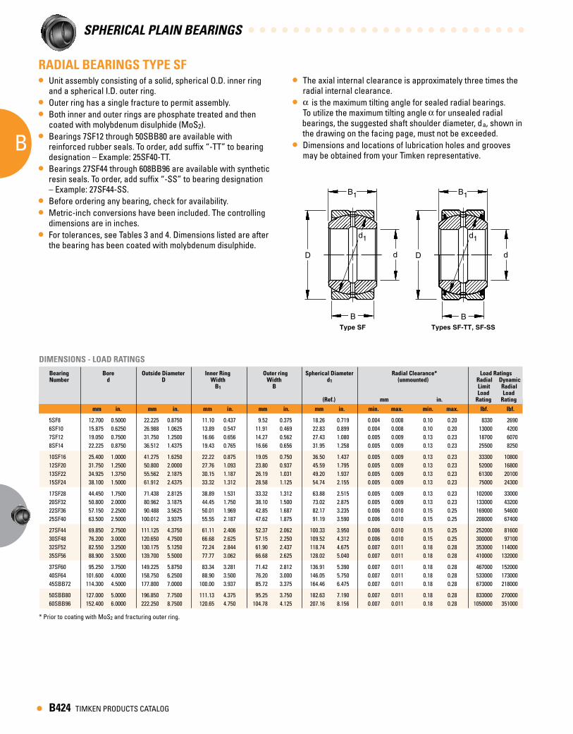
RADIAL BEARINGS TYPE SF• Unit assembly consisting of a solid, spherical O.D. inner ring
and a spherical I.D. outer ring.• Outer ring has a single fracture to permit assembly.• Both inner and outer rings are phosphate treated and then
coated with molybdenum disulphide (MoS2).• Bearings 7SF12 through 50SBB80 are available with
reinforced rubber seals. To order, add suffix “-TT” to bearing designation – Example: 25SF40-TT.
• Bearings 27SF44 through 608BB96 are available with synthetic resin seals. To order, add suffix “-SS” to bearing designation – Example: 27SF44-SS.
• Before ordering any bearing, check for availability.• Metric-inch conversions have been included. The controlling
dimensions are in inches.• For tolerances, see Tables 3 and 4. Dimensions listed are after
the bearing has been coated with molybdenum disulphide.
DIMENSIONS - LOAD RATINGS
Bearing Bore Outside Diameter Inner Ring Outer ring Spherical Diameter Radial Clearance* Load RatingsNumber d D Width Width d1 (unmounted) Radial Dynamic
B1 B Limit Radial Load Load (Ref.) mm in. Rating Rating
mm in. mm in. mm in. mm in. mm in. min. max. min. max. lbf. lbf.
5SF8 12.700 0.5000 22.225 0.8750 11.10 0.437 9.52 0.375 18.26 0.719 0.004 0.008 0.10 0.20 8330 26906SF10 15.875 0.6250 26.988 1.0625 13.89 0.547 11.91 0.469 22.83 0.899 0.004 0.008 0.10 0.20 13000 42007SF12 19.050 0.7500 31.750 1.2500 16.66 0.656 14.27 0.562 27.43 1.080 0.005 0.009 0.13 0.23 18700 60708SF14 22.225 0.8750 36.512 1.4375 19.43 0.765 16.66 0.656 31.95 1.258 0.005 0.009 0.13 0.23 25500 8250
10SF16 25.400 1.0000 41.275 1.6250 22.22 0.875 19.05 0.750 36.50 1.437 0.005 0.009 0.13 0.23 33300 1080012SF20 31.750 1.2500 50.800 2.0000 27.76 1.093 23.80 0.937 45.59 1.795 0.005 0.009 0.13 0.23 52000 1680013SF22 34.925 1.3750 55.562 2.1875 30.15 1.187 26.19 1.031 49.20 1.937 0.005 0.009 0.13 0.23 61300 2010015SF24 38.100 1.5000 61.912 2.4375 33.32 1.312 28.58 1.125 54.74 2.155 0.005 0.009 0.13 0.23 75000 24300
17SF28 44.450 1.7500 71.438 2.8125 38.89 1.531 33.32 1.312 63.88 2.515 0.005 0.009 0.13 0.23 102000 3300020SF32 50.800 2.0000 80.962 3.1875 44.45 1.750 38.10 1.500 73.02 2.875 0.005 0.009 0.13 0.23 133000 4320022SF36 57.150 2.2500 90.488 3.5625 50.01 1.969 42.85 1.687 82.17 3.235 0.006 0.010 0.15 0.25 169000 5460025SF40 63.500 2.5000 100.012 3.9375 55.55 2.187 47.62 1.875 91.19 3.590 0.006 0.010 0.15 0.25 208000 67400
27SF44 69.850 2.7500 111.125 4.3750 61.11 2.406 52.37 2.062 100.33 3.950 0.006 0.010 0.15 0.25 252000 8160030SF48 76.200 3.0000 120.650 4.7500 66.68 2.625 57.15 2.250 109.52 4.312 0.006 0.010 0.15 0.25 300000 9710032SF52 82.550 3.2500 130.175 5.1250 72.24 2.844 61.90 2.437 118.74 4.675 0.007 0.011 0.18 0.28 353000 11400035SF56 88.900 3.5000 139.700 5.5000 77.77 3.062 66.68 2.625 128.02 5.040 0.007 0.011 0.18 0.28 410000 132000
37SF60 95.250 3.7500 149.225 5.8750 83.34 3.281 71.42 2.812 136.91 5.390 0.007 0.011 0.18 0.28 467000 15200040SF64 101.600 4.0000 158.750 6.2500 88.90 3.500 76.20 3.000 146.05 5.750 0.007 0.011 0.18 0.28 533000 17300045SBB72 114.300 4.5000 177.800 7.0000 100.00 3.937 85.72 3.375 164.46 6.475 0.007 0.011 0.18 0.28 673000 218000
50SBB80 127.000 5.0000 196.850 7.7500 111.13 4.375 95.25 3.750 182.63 7.190 0.007 0.011 0.18 0.28 833000 27000060SBB96 152.400 6.0000 222.250 8.7500 120.65 4.750 104.78 4.125 207.16 8.156 0.007 0.011 0.18 0.28 1050000 351000
* Prior to coating with MoS2 and fracturing outer ring.
• The axial internal clearance is approximately three times the radial internal clearance.
• is the maximum tilting angle for sealed radial bearings. To utilize the maximum tilting angle for unsealed radial bearings, the suggested shaft shoulder diameter, da, shown in the drawing on the facing page, must not be exceeded.
• Dimensions and locations of lubrication holes and grooves may be obtained from your Timken representative.
dD
B1
d1
BType SF Types SF-TT, SF-SS
dD
B1
d1
B

• TIMKEN PRODUCTS CATALOG B425
A
AB
Spherical Plain Bearings
MOUNTING• Housing bore dimensions listed below are applicable to bearings
mounted in steel.• Because of fracturing, the outer ring may be slightly out-of-round. • Roundness will be restored when the bearing is mounted in a
housing of sufficient cross section.• Preferred shaft and housing bore dimensions are listed below.• Refer to the m6 tolerance limits per ANSI B4.1 in the Shaft Diameter
Tolerance table on page B410 for a shaft interference fit.
MOUNTING DIMENSIONS
Weight Tilting Angle Shaft Shaft Housing Shaft Diameter Housing Bore Shoulder Fillet Fillet S H Diameter Radius* Radius ' da ra† rb‡ (Approx.) (Max.) (Max.) mm in. mm in.
kg lbs. deg. deg. mm in. mm in. mm in. max. min. max. min. max. min. min. max.
0.020 0.044 5.5 14 14.3 0.56 * * 0.6 0.022 12.695 12.685 0.4998 0.4994 22.197 22.217 0.8739 0.8747 0.036 0.079 6 14 17.8 0.70 * * 0.8 0.032 15.870 15.860 0.6248 0.6244 26.960 26.980 1.0614 1.0622 0.057 0.126 6 14.5 21.4 0.84 * * 0.8 0.032 19.042 19.029 0.7497 0.7492 31.717 31.742 1.2487 1.2497 0.087 0.193 6 14.5 25.0 0.98 * * 0.8 0.032 22.217 22.204 0.8747 0.8742 36.479 36.504 1.4362 1.4372
0.125 0.276 6 14.5 28.6 1.12 * * 0.8 0.032 25.392 25.379 0.9997 0.9992 41.242 41.267 1.6237 1.6247 0.234 0.516 6 14.5 35.7 1.41 * * 0.8 0.032 31.740 31.725 1.2496 1.2490 50.762 50.792 1.9985 1.9997 0.349 0.770 5.5 14 38.9 1.53 * * 0.8 0.032 34.915 34.900 1.3746 1.3740 55.524 55.554 2.1860 2.1872 0.424 0.934 6 14.5 43.3 1.70 * * 0.8 0.032 38.090 38.075 1.4996 1.4990 61.874 61.904 2.4360 2.4372
0.649 1.430 6 15.5 50.0 1.97 * * 0.8 0.032 44.440 44.425 1.7496 1.7490 71.399 71.429 2.8110 2.8122 0.939 2.070 6 15.5 57.2 2.25 * * 0.8 0.032 50.790 50.772 1.9996 1.9989 80.914 80.950 3.1856 3.1870 1.324 2.920 6 14 65.1 2.56 * * 0.8 0.032 57.140 57.122 2.2496 2.2489 90.439 90.475 3.5606 3.5620 1.855 4.090 6 14 72.2 2.84 * * 0.8 0.032 63.490 63.472 2.4996 2.4989 99.964 100.000 3.9356 3.9370
2.440 5.380 6 12 79.4 3.12 0.6 0.022 0.8 0.032 69.840 69.822 2.7496 2.7489 111.077 111.113 4.3731 4.3745 3.116 6.870 6 12 86.5 3.41 0.6 0.022 0.8 0.032 76.190 76.172 2.9996 2.9989 120.594 120.635 4.7478 4.7494 3.914 8.630 6 12 94.1 3.70 0.6 0.022 0.8 0.032 82.537 82.514 3.2495 3.2486 130.119 130.160 5.1228 5.1244 4.853 10.700 6 12 101.0 3.97 0.6 0.022 0.8 0.032 88.887 88.864 3.4995 3.4986 139.644 139.685 5.4978 5.4994
5.897 13.000 6 12 108.0 4.25 0.6 0.022 0.8 0.032 95.237 95.214 3.7495 3.7486 149.169 149.210 5.8728 5.8744 7.076 15.600 6 11.5 116.0 4.56 0.6 0.022 0.8 0.032 101.587 101.564 3.9995 3.9986 158.694 158.735 6.2478 6.2494 9.934 21.900 6 12 130.0 5.12 0.8 0.032 1.1 0.044 114.287 114.264 4.4995 4.4986 177.744 177.785 6.9978 6.9994
13.472 29.700 6 12 144.0 5.69 0.8 0.032 1.1 0.044 126.985 126.960 4.9994 4.9984 196.784 196.830 7.7474 7.7492 17.600 38.800 5 10.5 168.0 6.59 0.8 0.032 1.1 0.044 152.385 152.360 5.9994 5.9984 222.184 222.230 8.7474 8.7492
* For bearing sizes 5SF8 through 25SF40, shaft and shoulder should be undercut to eliminate fillet. † Equal to minimum inner ring bore chamfer.‡ Equal to minimum outer ring O.D. chamfer.
'
d a d a
r b
S r a H
Maximum tilt Maximum tilt Mounting detailfor sealed bearing for bearing without seals

• B426 TIMKEN PRODUCTS CATALOG
A
AB
SPHERICAL PLAIN BEARINGS
RADIAL BEARINGS TYPE FS• Type FS spherical plain radial bearing is a unit assembly
consisting of a solid, spherical O.D. inner ring and a spherical I.D. outer ring.
• The outer ring has a single fracture to permit assembly. Both inner and outer rings are phosphate treated and then coated with molybdenum disulphide (MoS2).
• Bearings 16FS30 through 60FS90 are available with reinforced rubber seals. To order, add suffix “TT” to bearing designation - Example: 16FS30-TT.
• Bearings 70FS105 through 300FS430 are available with synthetic resin seals. To order, add suffix “SS” to bearing designation - Example: 70FS105-SS.
• Before ordering any bearing, check for availability.• Type FS bearings are a metric series which follows proposed
International Standards Organization (ISO) standards. Metric-Inch conversions given are for the convenience of the user. The controlling dimensions are in millimeters.
DIMENSIONS - LOAD RATINGS
Bearing Bore Outside Diameter Inner Ring Outer ring Spherical Diameter Radial Clearance* Load Ratings Number d D Width Width d1 (unmounted) Radial Dynamic B1 B Limit Radial Load Load (Ref.) mm in. Rating Rating
mm in. mm in. mm in. mm in. mm in. min. max. min. max. lbf. lbf.
12FS22 12 .4724 22 0.8661 10 .394 7 .276 19 .748 0.10 0.22 .004 .009 8630 2290 14FS26 14 .5512 26 1.0236 12 .472 9 .354 22 .866 0.10 0.22 .004 .009 11600 3210 16FS30 16 .6300 30 1.1811 14 .551 10 .394 25 .984 0.10 0.22 .004 .009 14400 4280 20FS35 20 .7874 35 1.3780 16 .630 12 .472 30 1.181 0.12 0.24 .005 .010 21500 6110
24FS42 24 .9449 42 1.6142 20 .787 16 .630 36 1.417 0.12 0.24 .005 .010 31000 9170 30FS47 30 1.1811 47 1.8504 22 .866 18 .709 41 1.614 0.12 0.24 .005 .010 40200 12600 35FS55 35 1.3780 55 2.1654 25 .984 20 .787 48 1.890 0.12 0.24 .005 .010 55100 16700 40FS62 40 1.5748 62 2.4409 28 1.102 22 .866 55 2.165 0.12 0.24 .005 .010 72300 21400
45FS68 45 1.7717 68 2.6772 32 1.260 25 .984 60 2.362 0.12 0.24 .005 .010 86100 27500 50FS75 50 1.9685 79 2.9528 35 1.378 28 1.102 67 2.638 0.12 0.24 .005 .010 107000 33400 60FS90 60 2.3622 90 3.5433 44 1.732 36 1.417 81 3.150 0.14 0.26 .006 .011 157000 50400
70FS105 70 2.7559 105 4.1339 49 1.929 40 1.575 94 3.701 0.14 0.26 .006 .011 211000 65500 80FS120 80 3.1496 120 4.7244 55 2.165 45 1.772 107 4.213 0.14 0.26 .006 .011 274000 84100 90FS130 90 3.5433 130 5.1181 60 2.362 50 1.968 117 4.606 0.14 0.26 .006 .011 327000 103000 100FS150 100 3.9370 150 5.9055 70 2.756 55 2.165 134 5.276 0.14 0.26 .006 .011 429000 134000
110FS160 110 4.3307 160 6.2992 70 2.756 55 2.165 143 5.630 0.14 0.26 .006 .011 489000 147000 120FS180 120 4.7244 180 7.0866 85 3.346 70 2.756 160 6.299 0.14 0.26 .006 .011 612000 195000 140FS210 140 5.5118 210 8.2677 90 3.543 70 2.756 187 7.362 0.16 0.28 .006 .011 836000 241000 160FS230 160 6.2992 230 9.0551 105 4.134 80 3.150 206 8.110 0.16 0.28 .006 .011 1020000 321000
180FS260 180 7.0866 260 10.2362 105 4.134 80 3.150 234 9.213 0.16 0.28 .006 .011 1300000 361000 200FS290 200 7.8740 290 11.4173 130 5.118 100 3.937 265 10.433 0.18 0.30 .007 .012 1680000 497000 220FS320 220 8.6614 320 12.5984 135 5.315 100 3.937 286 11.260 0.18 0.30 .007 .012 1960000 568000 240FS340 240 9.4488 340 13.3858 140 5.512 100 3.937 306 12.047 0.18 0.30 .007 .012 2240000 642000
260FS370 260 10.2362 370 14.5669 150 5.906 110 4.331 333 13.110 0.20 0.32 .008 .013 2650000 745000 280FS400 280 11.0236 400 15.7480 155 6.102 120 4.724 360 14.173 0.20 0.32 .008 .013 3100000 829000 300FS430 300 11.8110 430 16.9291 165 6.496 120 4.724 386 15.197 0.20 0.32 .008 .013 3560000 946000
* Prior to fracturing outer ring.
• For tolerances of nominal dimensions see the tables 1 and 2 on page B423. Dimensions listed are before coating with molybdenum disulphide. The axial internal clearance is approximately three times the radial internal clearance.
• is the maximum tilting angle for sealed radial bearings. To utilize the maximum tilting angle for unsealed radial bearings the suggested shaft shoulder diameter da1 shown in the drawing on facing page must not be exceeded.
• Dimensions and locations of lubrication holes and grooves may be obtained from your Timken representative.
dD
B1
d1
B
dD
B1
d1
BType FS Type FS-TT, FS-SS

• TIMKEN PRODUCTS CATALOG B427
A
AB
Spherical Plain Bearings
MOUNTING• Due to fracturing, the outer ring may be slightly out-of-round.
Roundness will be restored, however, when the bearing is mounted in a housing of sufficient cross section.
• The preferred shaft tolerance is f6 as listed below per ANSI B4.2. To obtain a shaft interference fit, refer to the m6 tolerance limits listed in the Shaft Diameter Tolerance table on page B422.
LOAD RATING• The “dynamic load rating” is the maximum load suggested
for extended life with periodic lubrication. It is based upon the radially projected area of the inner ring bore and an allowable stress level of 85 megapascals (approximately 12,300 psi).
MOUNTING DIMENSIONS
Weight Tilting Angle Shaft Shaft Housing Shaft Diameter Housing Bore Shoulder Fillet Fillet S H Diameter Radius* Radius ' da ra† rb‡ (Approx.) (Max.) (Max.) mm in. mm in.
kg lbs. deg. deg. mm in. mm in. mm in. max. min. max. min. max. min. min. max.
.038 10.0 11.5 16 .63 0.5 .02 0.5 .02 11.984 11.973 .4718 .4714 21.977 21.995 .8650 .8658 .065 8.5 14.5 18 .71 0.5 .02 0.5 .02 13.984 13.973 .5506 .5502 25.972 25.993 1.0225 1.0233 .115 10.0 16.0 20 .79 0.5 .02 0.5 .02 15.984 15.973 .6293 .6289 29.972 29.993 1.1800 1.1808 .149 8.5 14.0 25 .98 0.5 .02 0.6 .02 19.980 19.967 .7866 .7861 34.967 34.992 1.3767 1.3777
.257 7.0 12.5 29 1.14 0.5 .02 0.6 .02 23.980 23.967 .9441 .9436 41.967 41.992 1.6522 1.6532 .337 6.0 10.5 34 1.38 0.5 .02 0.6 .02 29.980 29.967 1.1803 1.1798 46.967 46.992 1.8491 1.8501 .523 6.5 10.5 40 1.61 0.6 .02 0.8 .03 34.975 34.959 1.3770 1.3764 54.961 54.991 2.1638 2.1650 .729 7.0 10.5 47 1.85 0.6 .02 0.8 .03 39.975 39.959 1.5738 1.5732 61.961 61.991 2.4394 2.4406
.948 7.5 10.5 50 2.01 0.6 .02 0.8 .03 44.975 44.959 1.7707 1.7701 67.961 67.991 2.6756 2.6768 1.27 6.5 10.0 56 2.24 0.6 .02 0.8 .03 49.975 49.959 1.9675 1.9669 74.961 74.991 2.9512 2.9524 2.32 6.5 11.0 66 2.64 0.8 .03 1.0 .04 59.970 59.951 2.3610 2.3603 89.955 89.990 3.5415 3.5429
3.53 6.0 9.5 80 3.15 0.8 .03 1.0 .04 69.970 69.951 2.7547 2.7540 104.955 104.990 4.1321 4.1335 5.20 6.0 7.5 92 3.62 0.8 .03 1.0 .04 79.970 79.951 3.1484 3.1477 119.955 119.990 4.7226 4.7240 6.28 5.5 7.5 100 3.94 1.0 .04 1.0 .04 89.964 89.942 3.5419 3.5410 129.948 129.988 5.1161 5.1177 10.1 7.0 8.5 114 4.49 1.0 .04 1.0 .04 99.964 99.942 3.9356 3.9347 149.948 149.988 5.9035 5.9051
10.9 6.0 7.5 125 4.92 1.0 .04 1.0 .04 109.964 109.942 4.3293 4.3284 159.948 159.988 6.2972 6.2988 18.1 6.0 7.5 136 5.35 1.0 .04 1.0 .04 119.964 119.942 4.7230 4.7221 179.948 179.988 7.0846 7.0862 25.6 6.5 7.0 164 6.46 1.0 .04 1.0 .04 139.957 139.932 5.5101 5.5091 209.940 209.986 8.2654 8.2674 32.3 7.5 9.0 177 6.97 1.0 .04 1.0 .04 159.957 159.932 6.2975 6.2965 229.940 229.986 9.0528 9.0548
42.8 6.5 7.0 209 8.23 1.0 .04 1.0 .04 179.957 179.932 7.0849 7.0839 259.934 259.986 10.2336 10.2356 66.5 7.0 7.5 231 9.09 1.0 .04 1.0 .04 199.950 199.921 7.8720 7.8709 289.934 289.986 11.4147 11.4167 82.3 7.5 8.0 252 9.92 1.0 .04 1.0 .04 219.950 219.921 8.6594 8.6583 319.927 319.984 12.5956 12.5978 90.1 8.0 9.0 272 10.70 1.0 .04 1.0 .04 239.950 239.921 9.4468 9.4457 339.927 339.984 13.3830 13.3852
117 7.0 8.5 297 11.69 1.0 .04 1.0 .04 259.944 259.912 10.2340 10.2327 369.927 369.984 14.5641 14.5663 147 6.0 7.0 325 12.80 1.0 .04 1.0 .04 279.944 279.912 11.0214 11.0201 399.927 399.984 15.7452 15.7474 177 7.0 9.0 349 13.74 1.0 .04 1.0 .04 299.944 299.912 11.8088 11.8075 429.920 429.983 16.9260 16.9285
* For bearing sizes 5SF8 through 25SF40, shaft and shoulder should be undercut to eliminate fillet. † Equal to minimum inner ring bore chamfer.‡ Equal to minimum outer ring O.D. chamfer.
'
d a d a
r b
S r a H
Maximum tilt Maximum tilt Mounting detailfor sealed bearing for bearing without seals
• For intermittent loading and intermittent operation, the applied radial load should not exceed the dynamic load rating. For constant loading and continuous operation, the applied radial load should not exceed 75 percent of the dynamic load rating. For dynamic or static thrust loading, use 25 percent of respective radial load values. For combined radial and thrust loading, consult your Timken representative.
• The “limit load rating” is the maximum static load that can be applied to a Timken spherical plain bearing. Shaft and housing stresses should be checked when the load approaches the limit load rating since the shaft or housing may then become the critical member. The ultimate, or static fracture, rating of the bearing is at least 1.5 times the limit load rating.
• Load ratings are given in pounds-force: 1 lbf = 0.454kgf = 4.448 N.

• B428 TIMKEN PRODUCTS CATALOG
A
AB
SPHERICAL PLAIN BEARINGS
RADIAL BEARINGS TYPE FSH• The FSH spherical plain radial bearing is a unit assembly
consisting of a solid spherical O.D. inner ring and a spherical I.D. outer ring.
• The outer ring has a single fracture to permit assembly. Both inner and outer rings are phosphate treated and then coated with molybdenum disulphide (MoS2). The type FSH bearing is similar to type FS, but the inner ring bore diameter has been reduced and the width made greater to increase the spherical surface. This permits greater misalignment while maintaining full bearing contact.
• Bearings 14FSH30 through 50FSH90 are available with reinforced rubber seals. To order, add suffix “TT” to bearing designation - Example: 14FSH30-TT.
• Bearings 60FSH105 through 280FSH430 are available with synthetic resin seals. To order, add suffix “SS” to bearing designation - Example: 60FSH105-SS.
• Before ordering any bearing, check for availability.
DIMENSIONS• Type FSH bearings are a metric series which follows proposed
International Standards Organization (ISO) standards. Metric Inch conversions given are for the convenience of the user. The controlling dimensions are in millimeters.
DIMENSIONS - LOAD RATINGS
Bearing Bore Outside Diameter Inner Ring Outer ring Spherical Diameter Radial Clearance* Load RatingsNumber d D Width Width d1 (unmounted) Radial Dynamic
B1 B Limit Radial Load Load (Ref.) mm in. Rating Rating
mm in. mm in. mm in. mm in. mm in. min. max. min. max. lbf. lbf.
12FSH26 12 .4724 26 1.0236 15 .591 9 .354 22 .866 0.10 0.22 .004 .009 11600 344014FSH30 14 .5512 30 1.1811 16 .630 10 .394 25 .984 0.10 0.22 .004 .009 14400 428016FSH35 16 .6300 35 1.3780 20 .787 12 .472 30 1.181 0.12 0.24 .005 .010 21500 611020FSH42 20 .7874 42 1.6142 25 .984 16 .630 36 1.417 0.12 0.24 .005 .010 31000 955024FSH47 24 .9449 47 1.8504 28 1.102 18 .709 41 1.614 0.12 0.24 .005 .010 40200 12800
30FSH55 30 1.1811 55 2.1654 32 1.260 20 .787 48 1.890 0.12 0.24 .005 .010 55100 1830035FSH62 35 1.3780 62 2.4409 35 1.378 22 .866 55 2.165 0.12 0.24 .005 .010 72300 2340040FSH68 40 1.5748 68 2.6772 40 1.575 25 .984 60 2.362 0.12 0.24 .005 .010 86100 3060045FSH75 45 1.7717 75 2.9528 43 1.693 28 1.102 67 2.638 0.12 0.24 .005 .010 107000 3700050FSH90 50 1.9685 90 3.5433 56 2.205 36 1.417 81 3.150 0.14 0.26 .006 .011 157000 53500
60FSH105 60 2.3622 105 4.1339 63 2.480 40 1.575 94 3.701 0.14 0.26 .006 .011 211000 7220070FSH120 70 2.7559 120 4.7244 70 2.756 45 1.772 107 4.213 0.14 0.26 .006 .011 274000 9360080FSH130 80 3.1496 130 5.1181 75 2.953 50 1.968 117 4.606 0.14 0.26 .006 .011 327000 11500090FSH150 90 3.5433 150 5.9055 85 3.346 55 2.165 134 5.276 0.14 0.26 .006 .011 429000 146000100FSH160 100 3.9370 160 6.2992 85 3.346 55 2.165 143 5.630 0.14 0.26 .006 .011 489000 162000
110FSH180 110 4.3307 180 7.0866 100 3.937 70 2.756 160 6.299 0.14 0.26 .006 .011 612000 210000120FSH210 120 4.7244 210 8.2677 115 4.528 70 2.756 187 7.362 0.16 0.28 .006 .011 836000 264000140FSH230 140 5.5118 230 9.0551 130 5.118 80 3.150 206 8.110 0.16 0.28 .006 .011 1020000 348000160FSH260 160 6.2992 260 10.2362 135 5.315 80 3.150 234 9.213 0.16 0.28 .006 .011 1300000 413000180FSH290 180 7.0866 290 11.4173 155 6.102 100 3.937 265 10.433 0.18 0.30 .007 .012 1680000 533000
200FSH320 200 7.8740 320 12.5984 165 6.496 100 3.937 286 11.260 0.18 0.30 .007 .012 1960000 631000220FSH340 220 8.6614 340 13.3858 175 6.890 100 3.937 306 12.047 0.18 0.30 .007 .012 2240000 736000240FSH370 240 9.4488 370 14.5669 190 7.480 110 4.331 333 13.110 0.20 0.32 .008 .013 2650000 871000260FSH400 260 10.2362 400 15.7480 205 8.071 120 4.724 360 14.173 0.20 0.32 .008 .013 3100000 1020000280FSH430 280 11.0236 430 16.9291 210 8.268 120 4.724 386 15.197 0.20 0.32 .008 .013 3560000 1120000
* Prior to fracturing outer ring.
• For tolerances of nominal dimensions, see Tables 1 and 2 on page B411. Dimensions listed are before coating with molybdenum disulphide. The axial internal clearance is approximately three times the radial internal clearance.
• is the maximum tilting angle for sealed radial bearings. To utilize the maximum tilting angle for unsealed radial bearings, the suggested shaft shoulder diameter da1 shown in the drawing on facing page must not be exceeded.
• Dimensions and locations of lubrication holes and grooves may be obtained from your Timken representative.
dD
B1
B
d1
dD
B1
B
d1
Type FSH Type SFH TT, SFH SS

• TIMKEN PRODUCTS CATALOG B429
A
AB
Spherical Plain Bearings
MOUNTING• The housing bore dimensions given below are applicable to
bearings mounted in steel.• Due to fracturing, the outer ring may be slightly out-of-round.
Roundness will be restored, however, when the bearing is mounted in a housing of sufficient cross section.
• The preferred shaft tolerance is f6 as listed below per ANSI B4.2. To obtain a shaft interference fit, refer to the m6 tolerance limits listed in the Shaft Diameter Tolerance table on page B410.
LOAD RATING• The “dynamic load rating” is the maximum load suggested for
extended life with periodic lubrication. It is based upon the radially projected area of the inner ring bore and allowable stress level of 85 megapascals (approximately 12,300 psi).
MOUNTING DIMENSIONS
Weight Tilting Angle Shaft Shaft Housing Shaft Diameter Housing Bore Shoulder Fillet Fillet S H Diameter Radius* Radius ' da ra† rb‡ (Approx.) (Max.) (Max.) mm in. mm in.
lbs. deg. deg. mm in. mm in. mm in. max. min. max. min. max. min. min. max.
.069 18.5 25.0 16 .63 0.5 .02 0.5 .02 11.984 11.973 .4718 .4714 25.972 25.993 1.0225 1.0233
.130 16.0 22.0 19 .75 0.5 .02 0.5 .02 13.984 13.973 .5506 .5502 29.972 29.993 1.1800 1.1808
.171 18.0 27.0 21 .83 0.5 .02 0.6 .02 15.984 15.973 .6293 .6289 34.967 34.992 1.3767 1.3777
.298 17.5 26.5 24 .94 0.5 .02 0.6 .02 19.980 19.967 .7866 .7861 41.967 41.992 1.6522 1.6532
.397 17.0 23.0 29 1.14 0.5 .02 0.6 .02 23.980 23.963 .9441 .9436 46.967 46.992 1.8491 1.8501
.574 17.0 24.0 34 1.34 0.5 .02 0.8 .03 29.980 29.967 1.1803 1.1798 54.961 54.991 2.1638 2.1650
.794 15.5 24.5 39 1.54 0.6 .02 0.8 .03 34.975 34.959 1.3770 1.3764 61.961 61.991 2.4394 2.4406
.982 17.0 21.0 44 1.73 0.6 .02 0.8 .03 39.975 39.959 1.5738 1.5732 67.961 67.991 2.6756 2.67681.31 15.0 20.0 50 1.97 0.6 .02 0.8 .03 44.975 44.959 1.7707 1.7701 74.961 74.991 2.9512 2.95242.63 17.0 23.5 57 2.24 0.6 .02 1.0 .04. 49.975 49.959 1.9675 1.9669 89.955 89.990 3.5415 3.5429
3.91 16.5 22.5 67 2.64 0.8 .03 1.0 .04 59.970 59.951 2.3610 2.3603 104.955 104.990 4.1321 4.13355.62 15.5 20.5 77 3.03 0.8 .03 1.0 .04 69.970 69.951 2.7547 2.7540 119.955 119.990 4.7226 4.72406.66 14.5 18.5 87 3.43 0.8 .03 1.0 .04 79.970 79.951 3.1484 3.1477 129.948 129.988 5.1161 5.1177
10.4 15.0 19.5 98 3.86 1.0 .04 1.0 .04 89.964 89.942 3.5419 3.5410 149.948 149.988 5.9035 5.905111.5 13.5 18.0 110 4.33 1.0 .04 1.0 .04 99.964 99.942 3.9356 3.9347 159.948 159.988 6.2972 6.2988
17.9 12.5 15.5 122 4.80 1.0 .04 1.0 .04 109.964 109.942 4.3293 4.3284 179.948 179.988 7.0846 7.086229.7 15.5 23.5 132 5.20 1.0 .04 1.0 .04 119.964 119.942 4.7230 4.7221 209.940 209.986 8.2654 8.267435.8 16.0 20.5 152 5.98 1.0 .04 1.0 .04 139.957 139.932 5.5101 5.5091 229.940 229.986 9.0528 9.054848.9 15.0 21.0 176 6.93 1.0 .04 1.0 .04 159.957 159.932 6.2975 6.2965 259.934 259.986 10.2336 10.235671.5 13.0 20.5 196 7.72 1.0 .04 1.0 .04 179.957 179.932 7.0849 7.0839 289.934 289.986 11.4147 11.4167
88.2 14.5 19.5 220 8.66 1.0 .04 1.0 .04 199.950 199.921 7.8720 7.8709 319.927 319.984 12.5956 12.597896.4 15.5 19.0 243 9.57 1.0 .04 1.0 .04 219.950 219.921 8.6594 8.6583 339.927 339.984 13.3830 13.3852
124 15.5 19.5 263 10.35 1.0 .04 1.0 .04 239.950 239.921 9.4468 9.4457 369.927 369.984 14.5641 14.5663157 15.0 19.5 283 11.14 1.0 .04 1.0 .04 259.944 259.912 10.2340 10.2327 399.927 399.984 15.7452 15.7474188 14.5 20.0 310 12.20 1.0 .04 1.0 .04 279.944 279.912 11.0214 11.0201 429.920 429.983 16.9260 16.9285
* For bearing sizes 5SF8 through 25SF40, shaft and shoulder should be undercut to eliminate fillet. † Equal to minimum inner ring bore chamfer.‡ Equal to minimum outer ring O.D. chamfer.
'
da da
rb
Sra H
Maximum tilt Maximum tilt Mounting detailfor sealed bearing for bearing without seals
• For intermittent loading and intermittent operation, the
applied radial load should not exceed the dynamic load rating for constant loading and continuous operation, the applied radial load should not exceed 75 percent of the dynamic load rating. For dynamic or static thrust loading, use 25 percent of respective radial load rating values. For combined radial and thrust loading, consult your Timken representative.
• The “limit load rating” is the maximum static load that can be applied to a Timken spherical plain bearing. Shaft and housing stresses should be checked when the load approaches the limit load rating since the shaft or housing may then become the critical member. The ultimate or static fracture rating of the bearing is at least 1.5 times the limit load rating.
• Load ratings are given in pounds force: 1 lbf = 0.454 kgf = 4.448N.

• B430 TIMKEN PRODUCTS CATALOG
A
AB
SPHERICAL PLAIN BEARINGS
RADIAL BEARINGS TYPE SFH• The SFH spherical plain radial bearing is a unit assembly
consisting of a solid spherical O.D. inner ring and a spherical I.D. outer ring. The outer ring has a single fracture to permit assembly. Both inner and outer rings are phosphate treated and then coated with molybdenum disulphide (MoS2).
• The type SFH bearing is similar to type SF, but the inner ring bore diameter has been reduced and the width made greater to increase the spherical surface. This permits greater misalignment yet maintains full bearing contact.
• Bearings 12SFH24 through 22SFH40 are available with reinforced rubber seals. To order, add suffix “TT” to bearing designation - Example: 22SFH40-TT.
• Bearings 25SFH44 through 55SFH96 are available with synthetic resin seals. To order, add suffix “SS” to bearing designation - Example: 25SFH44-SS.
• Before ordering any bearing, check for availability.
DIMENSIONS• Inch-metric conversions given are for the convenience of the
user. The controlling dimensions are in inches.• For tolerances of nominal dimensions, see Tables 2 and
2A on page B411. Dimensions listed are after coating with
DIMINSIONS - LOAD RATINGS
Bearing Bore Outside Diameter Inner Ring Outer ring Spherical Diameter Radial Clearance* Load RatingsNumber d D Width Width d1 (unmounted) Radial Dynamic
B1 B Limit Radial Load Load (Ref.) mm in. Rating Rating
mm in. mm in. mm in. mm in. mm in. min. max. min. max. lbf. lbf.
12SFH24 31.750 1.2500 61.912 2.4375 35.31 1.390 28.58 1.125 54.74 2.155 0.13 0.23 .005 .009 75000 2140015SFH28 38.100 1.5000 71.438 2.8125 40.13 1.580 33.32 1.312 63.88 2.515 0.13 0.23 .005 .009 102000 2920017SFH32 44.450 1.7500 80.962 3.1875 46.23 1.820 38.10 1.500 73.02 2.875 0.13 0.23 .005 .009 133000 3930020SFH36 50.800 2.0000 90.488 3.5625 52.58 2.070 42.85 1.687 82.17 3.235 0.15 0.25 .006 .010 169000 5100022SFH40 57.150 2.2500 100.012 3.9375 58.88 2.318 47.62 1.875 91.19 3.590 0.15 0.25 .006 .010 208000 64000
25SFH44 63.500 2.5000 111.125 4.3750 64.64 2.545 52.37 2.062 100.33 3.950 0.15 0.25 .006 .010 252000 7840027SFH48 69.850 2.7500 120.650 4.7500 70.87 2.790 57.15 2.250 109.52 4.312 0.15 0.25 .006 .010 300000 9460030SFH52 76.200 3.0000 130.175 5.1250 76.76 3.022 61.90 2.437 118.74 4.675 0.18 0.28 .007 .011 353000 11200032SFH56 82.550 3.2500 139.700 5.5000 82.93 3.265 66.68 2.625 128.02 5.040 0.18 0.28 .007 .011 410000 13100035SFH60 88.900 3.5000 149.225 5.8750 90.42 3.560 71.42 2.812 136.91 5.390 0.18 0.28 .007 .011 467000 154000
37SFH64 95.250 3.7500 158.750 6.2500 94.95 3.738 76.20 3.000 146.05 5.750 0.18 0.28 .007 .011 533000 17300040SFH72 101.600 4.0000 177.800 7.0000 107.32 4.225 85.72 3.375 164.46 6.475 0.18 0.28 .007 .011 673000 20800045SFH80 114.300 4.5000 196.850 7.7500 119.13 4.690 95.25 3.750 182.63 7.190 0.18 0.28 .007 .011 833000 26000055SFH96 139.700 5.5000 222.250 8.7500 125.73 4.950 104.78 4.125 207.16 8.156 0.18 0.28 .007 .011 1050000 336000
* Prior to fracturing outer ring.
MoS2 except outer ring O.D. and internal clearance are before coating and fracturing. The axial internal clearance is approximately three times the radial internal clearance.
• is the maximum tilting angle for sealed radial bearings. To utilize the maximum tilting angle for unsealed radial bearings, the suggested shaft shoulder diameter da, shown in the drawing on facing page must not be exceeded.
• Dimensions and locations of lubrication holes and grooves may be obtained from your Timken representative.
dD
B1
B
d1
dD
B1
B
d1
Type SFH Type SFH TT, SFH SS

• TIMKEN PRODUCTS CATALOG B431
A
AB
Spherical Plain Bearings
MOUNTING• The housing bore dimensions given below are applicable to
bearings mounted in steel.• Due to fracturing, the outer ring may be slightly out-of-round.
Roundness will be restored, however, when the bearing is mounted in a housing of sufficient cross section.
• The preferred shaft tolerance is g6 as listed below per ANSI B4.1. To obtain a shaft interference fit, refer to the m6 tolerance limits listed in the Shaft Diameter Tolerance table on page B410.
LOAD RATING• The “dynamic load rating” is the maximum load suggested
for extended life with periodic lubrication. It is based upon the radially projected area of the inner ring bore and an allowable stress level of 85 megapascals (approximately 12,300 psi).
MOUNTING DIMENSIONS
Weight Tilting Angle Shaft Shaft Housing Shaft Diameter Housing Bore Shoulder Fillet Fillet S H Diameter Radius* Radius ' da ra† rb‡ (Approx.) (Max.) (Max.) mm in. mm in.
lbs. deg. deg. mm in. mm in. mm in. max. min. max. min. max. min. min. max.
1.00 8.5 16.5 41.9 1.64 1.0 .040 0.8 .032 31.740 31.725 1.2496 1.2490 61.874 61.904 2.4360 2.43721.60 7.0 15.5 49.8 1.95 1.0 .040 0.8 .032 38.090 38.075 1.4996 1.4990 71.399 71.429 2.8110 2.81222.50 7.5 16.0 56.6 2.22 1.5 .060 0.8 .032 44.440 44.425 1.7496 1.7490 80.914 80.950 3.1856 3.18703.70 8.0 16.0 63.2 2.48 1.5 .060 0.8 .032 50.790 50.772 1.9996 1.9989 90.439 90.475 3.5606 3.56204.40 8.5 16.5 69.6 2.74 1.5 .060 0.8 .032 57.140 57.122 2.2496 2.2489 99.964 100.000 3.9356 3.9370
6.50 8.5 14.0 76.7 3.02 2.0 .080 0.8 .032 63.490 63.472 2.4996 2.4989 111.077 111.113 4.3731 4.37458.00 8.5 14.0 83.6 3.28 2.0 .080 0.8 .032 69.840 69.822 2.7496 2.7489 120.594 120.635 4.7478 4.74949.60 8.5 14.0 90.7 3.56 2.0 .080 0.8 .032 76.190 76.172 2.9996 2.9989 130.119 130.160 5.1228 5.1244
11.7 8.5 14.0 97.5 3.83 2.0 .080 0.8 .032 82.537 82.514 3.2495 3.2486 139.544 139.685 5.4978 5.499415.0 9.5 15.0 103 4.04 2.0 .080 0.8 .032 88.887 88.864 3.4995 3.4986 149.169 149.210 5.8728 5.8744
19.5 9.0 14.5 111 4.36 2.0 .080 0.8 .032 95.237 95.214 3.7495 3.7486 158.694 158.735 6.2478 6.249422.5 9.0 14.5 125 4.90 2.0 .080 1.1 .044 101.587 101.564 3.9995 3.9986 177.744 177.785 6.9978 6.999430.0 9.0 14.5 138 5.44 2.0 .080 1.1 .044 114.287 114.264 4.4995 4.4986 196.784 196.830 7.7474 7.749245.0 6.5 12.0 165 6.48 2.0 .080 1.1 .044 139.685 139.660 5.4994 5.4984 222.184 222.230 8.7474 8.7492
* For bearing sizes 5SF8 through 25SF40, shaft and shoulder should be undercut to eliminate fillet. † Equal to minimum inner ring bore chamfer.‡ Equal to minimum outer ring O.D. chamfer.
'
da da
rb
Sra H
Maximum tilt Maximum tilt Mounting detailfor sealed bearing for bearing without seals
• For intermittent loading and intermittent operation, the applied radial load should not exceed the dynamic load rating. For constant loading and continuous operation, the applied radial load shoud not exceed 75 percent of the dynamic load rating. For dynamic or static thrust loading, use 25 percent of respective radial load rating values. For combined radial and thrust loading, consult your Timken representative.
• The “limit load rating” is the maximum static load that can be applied to a Timken spherical plain bearing. Shaft and housing stresses should be checked when the load approaches the limit load rating since the shaft or housing may then become the critical member. The ultimate, or static fracture, rating of the bearing is at least 1.5 times the limit load rating.
• Load ratings are given in pounds force: 1lbf = 0.454 kgf = 4.448N.

• B432 TIMKEN PRODUCTS CATALOG
A
AB
SPHERICAL PLAIN BEARINGS
ANGULAR CONTACT BEARINGS TYPE SBT• Separable assembly consisting of an inner and outer ring with
hemispherically shaped surfaces that mate with each other.• Both inner and outer rings are phosphate-treated and coated
with molybdenum disulphide (MoS2).• If a Timken ring is assembled with a ring of another make,
consult your Timken representative.• To order inner and outer rings separately, specify by adding
suffix “-OR” for outer ring or “-IR” for inner ring.• Metric-inch conversions are provided for the convenience of
the user. The controlling dimensions are in inches. • See Table 2 and 3 for tolerances. Dimensions listed are after
the bearing has been coated with molybdenum disulphide.• is the maximum tilting angle through the shaft. A stub shaft
can be used to obtain a larger angle.• Dimensions and locations of lubrication holes and grooves
may be obtained from your Timken representative.
DIMINSIONS - LOAD RATINGS
Bearing Bore Outside Diameter Inner Ring Outer ring Spherical Diameter Radial Clearance* Load RatingsNumber d D Width Width d1 (unmounted) Radial Dynamic
B1 B Limit Radial Load Load (Ref.) mm in. Rating Rating
mm in. mm in. mm in. mm in. mm in. min. max. min. max. lbf. lbf.
5SBT80 0.5000 12.700 0.8750 22.225 0.270 6.86 0.190 4.83 0.300 7.62 0.094 2.39 0.719 18.26 4600 18606SBT10 0.6250 15.875 1.0625 26.988 0.340 8.64 0.250 6.35 0.370 9.40 0.109 2.77 0.899 22.83 7600 30807SBT12 0.7500 19.050 1.2500 31.750 0.410 10.41 0.310 7.87 0.440 11.18 0.125 3.18 1.080 27.43 11100 45008SBT14 0.8750 22.225 1.4375 36.512 0.480 12.19 0.380 9.65 0.520 13.21 0.172 4.37 1.258 31.95 15400 6210
10SBT16 1.0000 25.400 1.6250 41.275 0.550 13.97 0.440 11.18 0.600 15.24 0.203 5.16 1.437 36.50 19400 786012SBT20 1.2500 31.750 2.0000 50.800 0.700 17.78 0.550 13.97 0.740 18.80 0.234 5.94 1.795 45.59 31000 1250013SBT22 1.3750 34.925 2.1875 55.562 0.770 19.56 0.600 15.24 0.840 21.34 0.281 7.14 1.937 49.20 37000 1510015SBT24 1.5000 38.100 2.4375 61.912 0.840 21.34 0.660 16.76 0.910 23.11 0.312 7.92 2.155 54.74 44500 18300
17SBT28 1.7500 44.450 2.8125 71.438 0.980 24.89 0.790 20.07 1.070 27.18 0.328 8.33 2.515 63.88 60000 2440020SBT32 2.0000 50.800 3.1875 80.962 1.130 28.70 0.920 23.37 1.230 31.24 0.375 9.52 2.875 73.02 79000 3230022SBT36 2.2500 57.150 3.5625 90.488 1.270 32.26 1.050 26.67 1.390 35.31 0.453 11.51 3.235 82.17 100000 4080025SBT40 2.5000 63.500 3.9375 100.012 1.420 36.07 1.180 29.97 1.540 39.12 0.500 12.70 3.590 91.19 126000 51500
27SBT44 2.7500 69.850 4.3750 111.125 1.560 39.62 1.275 32.38 1.700 43.18 0.515 13.08 3.950 100.33 154000 6215030SBT48 3.0000 76.200 4.7500 120.650 1.710 43.43 1.405 35.69 1.860 47.24 0.578 14.68 4.312 109.52 186000 7500032SBT52 3.2500 82.550 5.1250 130.175 1.860 47.24 1.545 39.24 2.030 51.56 0.656 16.66 4.675 118.74 218000 8750035SBT56 3.5000 88.900 5.5000 139.700 2.000 50.80 1.675 42.54 2.180 55.37 0.703 17.86 5.040 128.02 257000 102400
37SBT60 3.7500 95.250 5.8750 149.225 2.150 54.61 1.805 45.85 2.340 59.44 0.765 19.43 5.390 136.91 295000 11850040SBT64 4.0000 101.600 6.2500 158.750 2.300 58.42 1.935 49.15 2.500 63.50 0.781 19.84 5.750 146.05 336000 13500045SBT72 4.5000 114.300 7.0000 177.800 2.590 65.79 2.195 55.75 2.800 71.12 0.875 22.22 6.475 164.46 432000 17350050SBT80 5.0000 127.000 7.7500 196.850 2.880 73.15 2.455 62.36 3.130 79.50 1.000 25.40 7.190 182.63 524000 21100060SBT96 6.0000 152.400 8.7500 222.250 3.100 78.74 2.615 66.42 3.375 85.72 1.370 34.80 8.156 207.16 585000 235000
d
d1
KBW B1
D

• TIMKEN PRODUCTS CATALOG B433
A
AB
Spherical Plain Bearings
S
da
rb
ra
H
db
Maximum tilt for bearing Mounting detail
MOUNTING DIMENSIONS
Weight Tilting Shaft Shaft Housing Housing Shaft Diameter Housing Bore Angle Shoulder Fillet Shoulder Filet S H Diameter Radius Diameter Radius da ra† db rb‡ (Approx.) (Max.) (Max.) (Max.) mm in. mm in.
kg lbs. deg. mm in. mm in. mm in. mm in. max. min. max. min. min. max. min. max.
0.013 0.029 7 0.67 17.0 0.020 0.5 0.57 14.5 0.020 0.5 0.4998 0.4994 12.695 12.685 0.8739 0.8747 22.197 22.2170.025 0.056 6 0.84 21.3 0.030 0.8 0.70 17.8 0.030 0.8 0.6248 0.6244 15.870 15.860 1.0614 1.0622 26.960 26.9800.038 0.083 6 1.02 25.9 0.040 1.0 0.84 21.3 0.040 1.0 0.7497 0.7492 19.042 19.029 1.2487 1.2497 31.717 31.7420.050 0.110 5.5 1.23 31.2 0.080 2.0 0.97 24.6 0.080 2.0 0.8747 0.8742 22.217 22.204 1.4362 1.4372 36.479 36.504
0.085 0.188 6 1.40 35.6 0.080 2.0 1.12 28.4 0.080 2.0 0.9997 0.9992 25.392 25.379 1.6237 1.6247 41.242 41.2670.159 0.351 6 1.71 43.4 0.080 2.0 1.39 35.3 0.080 2.0 1.2496 1.2490 31.740 31.725 1.9985 1.9997 50.762 50.7920.213 0.470 4 1.89 48.0 0.100 2.5 1.48 37.6 0.100 2.5 1.3746 1.3740 34.915 34.900 2.1860 2.1872 55.524 55.5540.300 0.662 5.5 2.05 52.1 0.100 2.5 1.66 42.2 0.100 2.5 1.4996 1.4990 38.090 38.075 2.4360 2.4372 61.874 61.904
0.458 1.010 6 2.36 59.9 0.100 2.5 1.95 49.5 0.100 2.5 1.7496 1.7490 44.440 44.425 2.8110 2.8122 71.399 71.4290.671 1.480 5.5 2.75 69.8 0.140 3.6 2.22 56.4 0.140 3.6 1.9996 1.9989 50.790 50.772 3.1856 3.1870 80.914 80.9500.948 2.090 5.5 3.06 77.7 0.140 3.6 2.50 63.5 0.140 3.6 2.2496 2.2489 57.140 57.122 3.5606 3.5620 90.439 90.4751.129 2.490 5 3.37 85.6 0.140 3.6 2.75 69.9 0.140 3.6 2.4996 2.4989 63.490 63.472 3.9356 3.9370 99.964 100.000
1.751 3.860 5 3.71 94.2 0.180 4.6 3.03 77.0 0.180 4.6 2.7496 2.7489 69.840 69.822 4.3731 4.3745 111.077 111.1132.277 5.020 5 4.07 103.0 0.180 4.6 3.30 83.8 0.180 4.6 2.9996 2.9989 76.190 76.172 4.7478 4.7494 120.594 120.6352.885 6.360 5 4.42 112.0 0.180 4.6 3.58 90.9 0.180 4.6 3.2495 3.2486 82.537 82.514 5.1228 5.1244 130.119 130.1603.570 7.870 5 4.77 121.0 0.180 4.6 3.85 97.8 0.180 4.6 3.4995 3.4986 88.887 88.864 5.4978 5.4994 139.644 139.685
4.350 9.590 4.5 5.11 130.0 0.180 4.6 4.10 104.0 0.180 4.6 3.7495 3.7486 95.237 95.214 5.8728 5.8744 149.169 149.2105.262 11.600 4.5 5.43 138.0 0.180 4.6 4.37 111.0 0.180 4.6 3.9995 3.9986 101.587 101.564 6.2478 6.2494 158.694 158.7357.756 17.100 4.5 6.14 156.0 0.180 4.6 4.90 125.0 0.180 4.6 4.4995 4.4986 114.287 114.264 6.9978 6.9994 177.744 177.785
11.068 24.400 4.5 6.83 174.0 0.180 4.6 5.47 139.0 0.180 4.6 4.9994 4.9984 126.984 126.959 7.7474 7.7492 196.784 196.83017.373 38.300 4.5 7.75 197.0 0.180 4.6 6.50 165.0 0.180 4.6 5.9994 5.9984 152.385 152.360 8.7474 8.7492 222.184 222.230
† Equal to minimum inner ring bore chamfer.‡ Equal to minimum outer ring O.D. chamfer.
MOUNTING• Housing bore dimensions listed are appropriate for bearings
mounted in steel.• Suggested diameters of shoulder supports should be used to
assure proper function of the bearing.• Preferred shaft and housing bore dimensions are listed below
per ANSI B4.1.• Refer to the m6 tolerance limits listed in the Shaft Diameter
Tolerance table on page B410 for shaft interference fit.• Bearings are to be mounted with sufficient axial preload
to ensure contact of the spherical surfaces under all load conditions.

• B434 TIMKEN PRODUCTS CATALOG
A
AB
SPHERICAL PLAIN BEARINGS

A
AB
Thrust BearingsThrust
•TIMKEN PRODUCTS CATALOG B435
THRUST BEARINGS
Overview: Timken thrust bearings are designed specifically to manage thrust loads and provide high-shock-load resistance in industrial and automotive applications. We manufacture seven basicdesigns of thrust bearings that include ball, crossed roller, cylindrical, machined tapered (TTHD, V-Flat,screwdown), stamped tapered, spherical and needle.
• Sizes: 35 mm - 2940 mm (1375 in. - 115.75 in.).
• Markets: Aggregate, Machine Tool, Metals, Oil, Power Generation.
• Applications: Cone crushers, crane hooks, oil well swivels, extruders, pulverizer drives, rolling mills,machine tool spindles & tables, drilling rig hydraulic heads, gear boxes, pre-heater fans.
• Benefits: High performance and application flexibility. Large range of product offering.
FPO

B
• B436 TIMKEN PRODUCTS CATALOG
Ball and Roller Thrust Bearings
From the three-digit “Series” number, it is knownthis is an inch size bearing. “50” is read as “5.0” and represents approximate or actual bore.
The series number (always three numerals) represents a specific size cage assembly.
50 TVB 190 A A XXX190
TVB thrust ball bearingsTVL angular contact thrust ball bearings
DTVL angular contact thrust ball bearings – upper and lower complement of balls
TSR thrust spherical roller bearings TTVF thrust tapered roller bearings
TTVS thrust tapered roller bearings – with aligning washer
TTSV, TTSX thrust tapered roller bearings – full complement
TP thrust cylindrical roller bearings TPS thrust cylindrical roller bearings –
with aligning washerTTHD thrust tapered roller bearings
modification modification descriptive ofto inner ring to outer ring modification code
•

B
Thrust BearingsThrust
• TIMKEN PRODUCTS CATALOG B437
Ball and Roller ThrustBearings Page
Introduction . . . . . . . . . . . . . . . . . . . . . . . . . . . . . . . . . . . . . . . B438
Ball and Roller Thrust Bearing Types . . . . . . . . . . . . . . . . . . B438
DIMENSIONS – LOAD RATINGS
Ball Thrust Bearing Type TVB . . . . . . . . . . . . . . . . . . . . . . . . B442
Angular Contact Ball Thrust Bearing Type TVL . . . . . . . . . . B443
Angular Contact Ball Thrust Bearing Type DTVL . . . . . . . . . B444
Spherical Roller Thrust Bearing Type TSR . . . . . . . . . . . . . . B445
Cylindrical Roller Thrust Bearing Type TP . . . . . . . . . . . . . . . B447
Cylindrical Roller Thrust Bearing Type TPS . . . . . . . . . . . . . B449
Crossed Roller Thrust Bearing Type XR and JXR . . . . . . . . . B451
Tapered Roller Thrust Bearing Type TTHD . . . . . . . . . . . . . . B452
Tapered Roller Thrust Bearing Type TTVF . . . . . . . . . . . . . . B457
Tapered Roller Thrust Bearing Type TTVS . . . . . . . . . . . . . . B458
Tapered Roller Thrust Bearing Type TTSX . . . . . . . . . . . . . . B459
Tapered Roller Thrust Bearing Type TTSV . . . . . . . . . . . . . . B460
Stamped Roller Thrust Bearing Type TTSP . . . . . . . . . . . . . B461
Stamped Tapered Roller Thrust Bearing Type TTC, TTCS . . B463

A
AB
ROLLER BEARINGS• B438 TIMKEN PRODUCTS CATALOG
TVB
Six basic designs of ball and roller thrust bearings are available: ball, cross roller, cylindrical, machine tapered (TTHD, V-Flat, Screwdown), stamped tapered and spherical tapered roller. Dimensional data for all styles are presented in order bybore size.
Engineering data such as tolerances, shaft and housing fits, and life and load rating calculations are found in the engineering section of this catalog.
INTRODUCTION
BEARING TYPESBALL THRUST BEARINGS
Ball thrust bearings provide optimum performance in high-speed installations, particularly where loads are generally lighter. Two types including axial (TVB), and angular contact (TVL) are available. The DTVL Type is offered with both an upper and lower complement of angular contact balls and three race elements. The standard tolerances for ball thrust bearings (both types) are equivalent to ABEC 1 where applicable. Higher precision tolerances are available. Consult your Timken representative for information on such installations.
TVBTVB Types are separable, consisting of two hardened and ground steel washers. Precision
ground and lapped balls run in a grooved raceway separated by a bronze cage. Other materials may be specified for the cage, depending on the application.
Most TVB bearings include washers of the same bore and outside diameter. Housings should be designed to clear the O.D. of rotating races, with shafts stepped to clear the bore of stationary washers. Provides axial rigidity, but are not suggested if radial load is expected. The TVB is exceptionally easy to mount with the rotating washer usually shaft mounted. The stationary washer should be housed with an outside diameter clearance that allows the bearing to assume a normal operating position.
TVLTVL Types provide exceptionally low friction, are cool running and have quiet operation when
operated at high speeds. They are also less sensitive to misalignment. Consult your Timken representative for assistance in determining limits of such loading for specific applications.
Although ball thrust bearings have been designed exclusively for thrust loads, the TVL bearing will accommodate some radial loading. Consult your Timken representative for assistance in determining the limits of such loading for specific applications.
Hardened and ground steel races of TVL bearings enclose a complement of precision ground and lapped steel balls, separated by a bronze cage. Other material may be specified as required.
Not strictly an annular ball bearing, the larger ring is identified as the outer ring; the smaller as the inner. Inner ring is usually the rotating element and is shaft mounted. Outer ring is normally stationary and should be mounted with an outside diameter clearance that allows the bearing to assume a normal operating position. If combined loads are expected, the outer ring must be radially located in the housing.
TVL bearings should always be operated under thrust loading. If a constant thrust load is not normally present, it should be imposed by springs or other devices.
DTVLThe DTVL has an upper and lower complement of angular contact balls and three race
elements. It is capable of carrying thrust in one direction, comparable to the TVL Series and lighter thrust in the opposite direction.
TVL
DTVL
TVB
TVL
DTVL

A
AB
Thrust BearingsThrust
• TIMKEN PRODUCTS CATALOG B439
TSR
SPHERICAL ROLLER THRUST BEARINGS
TSRA combination radial and thrust bearing designed to operate even if shaft and housing are,
or become, misaligned under load. A favored bearing when conditions include heavy loads, difficulties in establishing or maintaining housing alignment or when shaft deflection can be expected.
Shaft deflections and housing distortions caused by shock or heavy loads (which lead to misalignment) are compensated for by the internal self-alignment of the bearing elements during operation. Corner loading of rollers, a condition that limits service life on other types of bearings, cannot develop in spherical roller thrust bearings.
The TSR achieves high thrust capacity and allows axial misalignment between the inner ring and the outer ring of up to ±2.5˚. Spherically contoured rollers, arranged in a steep angular position, not only accept high axial loads, but also moderate radial loads. "E" styles, (EM-machined bronze cage, EJ- stamped steel cage) have increased capacity. Should extreme conditions of loading and/or speed under misalignment be anticipated, contact your Timken representative before ordering.
The inherent compensation for misalignment, provided by the spherical roller bearings, offers the designer the opportunity to use weldments for housing frames instead of complex castings. This eliminates high-cost machining operations. When castings are preferred, bore alignment is less critical if spherical roller bearings are specified.
CYLINDRICAL ROLLER THRUST BEARINGSTimken's cylindrical roller thrust bearings are designed to operate under heavy loads at
moderate speeds. Standard versions can be operated at peripheral speeds (bearing O.D.) of up to 3000 feet per minute. Special design features are available for both the bearing and mounting permitting even higher rotational speeds for this type of bearing. Two types of cylindrical roller thrust bearings, TP and TPS, are available.
TPType TP bearings include two flat hardened and ground steel washers with a cage retainer
holding one or more controlled contour rollers in each pocket. If specifications call for two or more rollers per pocket, they are manufactured to different lengths. The longer rollers are placed in alternate positions in adjacent pockets. Overlapping roller paths prevent "grooving" of the races and prolong bearing life. Due to the simplicity of design, standard TP thrust bearings are among the most economical to buy and install.
Minor radial displacement of the races does not affect the operation of the TP bearing, resulting in manufacturing economies and simplified installation.
Shaft and housing seats must be square to the axis of rotation to prevent initial misalignment problems.
TPSThe TPS design is similar to the TP style, except the bottom washer assembly is comprised
of two races, with the contacting faces spherically ground. The TPS bearing is self-adjusting to initial misalignment. It is not suggested for installations where alignment may be continuously changing (dynamic misalignment).
TXRThe crossed roller bearing is ideal for machine tool applications such as vertical boring mills,
vertical grinding machines and other similar applications. A crossed roller bearing is comprised of two sets of bearing races and rollers brought together at right angles to each other – with alternate rollers facinig in oposite directions – and within a section height not much greater than that of a single bearing housing.
TP
TPS
TSR
TSR-EJ
TSR-EM
TP
TPS
TXR

A
AB
ROLLER BEARINGS• B440 TIMKEN PRODUCTS CATALOG
TAPERED ROLLER THRUST BEARINGS Timken true rolling tapered roller thrust bearings include rollers that have conical sections.
These bearings have been engineered so that the rollers and raceways form a cone in which the vertex is on the center line of the bearing. This bearing geometry assures a true rolling motion. In addition, the large end of each tapered roller is spherically ground so that its curvature conforms with the concave face of the washer rib. Pressure between the rib and roller, under load, guides the rollers accurately. Timken manufactures five types of tapered roller thrust bearings: standard (TTHD), V-Flat (TTVF) self-aligning V-Flat (TTVS), concave washer (TTSV), and convex washer (TTSX).
TTHDThe TTHD design has an identical pair of hardened and ground steel washers with tapered
raceways. Both washers have the same bore and O.D., therefore housings should be designed to clear the O.D. of rotating washers and shafts stepped to clear the bore of stationary washers. Controlled contour tapered rollers are equally spaced by a cage. The TTHD bearing is well-suited for applications where extremely high thrust loads and heavy shock may be encountered as in crane hooks. For very low speed applications with unusually high loading, TTHD bearings can be supplied with a full complement of rollers. These bearings are identified in the tables by suffix 00278 following the bearing number. Applications for full-complement bearings should be reviewed by your Timken representative to ensure selection of the proper bearing.
TTVF, TTVS, TTSV, TTSXV-Flat Tapered Roller thrust bearings (TTVF and TTVS) combine the outstanding features
of tapered thrust and cylindrical roller bearings, offering the highest possible capacity of any thrust bearing of its size. The V-Flat design includes one flat washer and one with a tapered raceway matching the rollers. The design was originally developed for screwdown applications in metal rolling mills where thrust loads exceeding one million pounds are common. The V-Flat bearings have exceptional dynamic capacity within a given envelope and provides static capacity. They have been highly successful in heavily loaded extruders, in cone crushers and other applications where a wide range of operating conditions are found. Most sizes utilize cages with hardened pins through the center of the rollers, allowing closer spacing of the rollers to maximize capacity.
Smaller sizes have brass cages, designed for unidirectional retention of rollers.Both the pin type and brass cage are designed to permit a full flow of lubricant to all critical
surfaces, providing cooler operation.Self-aligning V-Flat bearings (TTVS) employ the same basic roller and raceway design, except
the lower washer is in two pieces, with the contacting faces spherically ground permitting self-alignment under conditions of initial misalignment. TTVS bearings should not used if dynamic misalignment (changing under load) is expected.
• The contact surface of each roller of the V-Flat bearings has a controlled contour wherein the ends are slightly relieved. This optimizes stress distribution by avoiding concentration of stress in the raceways at the ends of the rollers.
• Conformity between roller end and the rib is controlled to enhance the flow of lubricant between these surfaces, allowing the development of a hydrodynamic oil film between the end of the roller and the guiding surface of the rib.
• Full roller complement designs (TTSV and TTSX) do not have conventional bores, but are provided with center inserts for attachment purposes as well as for lifting.
• The TTSV and TTSX designs offer the highest capacity but at a somewhat reduced speed capability as compared with other V-Flat types.
• The TTSV and TTSX bearings encompass tapered rollers between two raceways. One raceway is flat and the other raceway forms the surface of a cone. The conical raceway has a washer with a rib to resist the radial component of the thrust force caused by the inclined plane and to guide the rollers.
TTVF
TTVS
TTHD
TTVF
TTVS
TTSV
TTSX

A
AB
Thrust BearingsThrust
• TIMKEN PRODUCTS CATALOG B441
• Lines extended from the TTSV and TTSX roller-to-raceway contact surfaces converge to form a cone. The vertex of this cone is common with the centerline of the bearing and the plane of the raceway surface of the flat washer.
• The TTSV and TTSX design achieves true rolling motion between the tapered rollers and both raceways with no sliding or skidding at any point on the rolling surfaces. The flat raceway permits radial displacement without affecting the operation of the bearing.
TTSPThe types TTSP and TTSPS (not shown) thrust bearings are made up of two tapered thrust
races, rollers, cage and outside retainer which holds the components together during shipping and installation. The types TTSP and TTSPS thrust bearings are exployed extensively in the steering pivot positions of automotive and industrial applications.
TTC, TTCSThe types TTC, TTCS and TTCL (not shown) thrust bearings consist of two tapered thrust
races, rollers and an outside retainer and are cageless. The outside retainer holds the assembly together for shipping and installation. Types TTC, TTCS and TTCL bearings are thrust bearings specifically designed for oscillating applications These types are identical with the exception of the retainer construction.

A
AB
ROLLER BEARINGS• B442 TIMKEN PRODUCTS CATALOG
Shoulder Diameter Load Rating
Bearing Bore O.D. Height Shaft Housing Fillet Radius(1) Wt. Static Load Dynamic LoadNumber d D T H E r Rating Rating
(min.) (min.) (max.) (max.) Coa Ct
mm mm mm mm mm mm kg kN kN in. in. in. in. in. in. lbs. lbs. lbs.
50TVB190 127.000 184.150 41.275 170.7 140.5 2.4 3.4 583.0 169.05.0000 7.2500 1.6250 6.72 5.53 0.09 7.2 131000 38000
52TVB253 133.350 203.200 50.800 185.7 150.8 2.4 5.5 756.0 223.05.2500 8.0000 2.0000 7.31 5.94 0.09 12.2 170000 50200
55TVB245 139.700 209.550 47.625 192.1 157.2 2.4 5.1 770.0 231.05.5000 8.2500 1.8750 7.56 6.19 0.09 11.3 173000 52000
57TVB248 146.050 215.900 47.625 198.4 163.5 2.4 5.3 810.0 239.05.7500 8.5000 1.8750 7.81 6.44 0.09 11.7 182000 53800
60TVB252 152.400 222.250 47.625 204.8 169.9 2.4 5.6 832.0 238.06.0000 8.7500 1.8750 8.06 6.69 0.09 12.4 187000 53500
62TVB291 158.750 228.600 47.625 215.1 172.2 2.4 5.8 867.0 245.06.2500 9.0000 1.8750 8.47 6.78 0.09 12.8 195000 55100
65TVB293 165.100 241.300 57.150 224.6 181.8 3.2 7.7 1060.0 317.06.5000 9.5000 2.2500 8.84 7.16 0.12 17.0 238000 71300
67TVB296 171.450 247.650 57.150 229.4 189.7 3.2 7.9 1110.0 328.06.7500 9.7500 2.2500 9.03 7.47 0.12 17.5 251000 73800
70TVB298 177.800 254.000 57.150 235.7 196.1 3.2 8.2 1170.0 339.07.0000 10.0000 2.2500 9.28 7.72 0.12 18.1 263000 76300
75TVB343 190.500 266.700 57.150 250 207.2 3.2 9.1 1140.0 321.07.5000 10.5000 2.2500 9.84 8.16 0.12 20.0 255000 72300
75TVB344 190.500 276.225 69.850 258.8 208 3.2 12.7 1390.0 407.07.5000 10.8750 2.7500 10.19 8.19 0.12 27.9 313000 91400
80TVB346 203.200 279.400 57.150 262.7 219.9 3.2 8.8 1370.0 395.08.0000 11.0000 2.2500 10.34 8.66 0.12 19.3 309000 88900
80TVB347 203.200 295.275 76.200 273.1 222.2 6.4 15.6 1700.0 504.08.0000 11.6250 3.0000 10.75 8.75 0.25 34.5 382000 113000
85TVB391 215.900 292.100 57.150 275.4 232.6 3.2 10.1 1280.0 349.08.5000 11.5000 2.2500 10.84 9.16 0.12 22.2 289000 78400
90TVB393 228.600 304.800 57.150 288.1 245.3 3.2 9.7 1620.0 442.09.0000 12.0000 2.2500 11.34 9.66 0.12 21.3 365000 99400
95TVB431 241.300 317.500 57.150 300.8 258 3.2 11.1 1380.0 366.09.5000 12.5000 2.2500 11.84 10.16 0.12 24.4 311000 82400
100TVB433 254.000 342.900 57.150 324.6 272.3 6.4 13.4 1560.0 431.010.0000 13.5000 2.2500 12.78 10.72 0.25 29.5 351000 96800
105TVB471 266.700 355.600 57.150 337.3 285.0 6.4 13.9 1810.0 476.010.5000 14.0000 2.2500 13.28 11.22 0.25 30.7 407000 107000
110TVB472 279.400 368.300 57.150 350 297.7 6.4 14.5 1870.0 486.011.0000 14.5000 2.2500 13.78 11.72 0.25 31.9 421000 109000
120TVB511 304.800 393.700 57.150 375.4 323.1 6.4 15.6 2000.0 507.012.0000 15.5000 2.2500 14.78 12.72 0.25 34.5 450000 114000
130TVB551 330.200 419.100 63.500 400.8 348.5 6.4 18 2470.0 627.013.0000 16.5000 2.5000 15.78 13.72 0.25 39.6 555000 141000
140TVB581 355.600 444.500 63.500 426.2 373.9 6.4 19.2 2620.0 649.014.0000 17.5000 2.5000 16.78 14.72 0.25 42.3 590000 146000
150TVB610 381.000 482.600 63.500 460.4 403.6 6.4 24.8 2620.0 649.015.0000 19.0000 2.5000 18.12 15.89 0.25 54.7 590000 146000
160TVB640 406.400 508.000 63.500 482.6 431.8 6.4 26.3 2780.0 677.016.0000 20.0000 2.5000 19.00 17.00 0.25 57.9 624000 152000
(1) Maximum shaft or housing fillet radius that bearing corners will clear.
BALL THRUST BEARINGSTYPE TVB• Designed for optimum performance in high
speed installations.• Provide axial rigidity, but are not suggested if
radial loading is expected.• Exceptionally easy to mount, with the rotating
washer usually shaft-mounted.
DIMENSIONS – LOAD RATINGS
H
d
r
T
D
r
E
r

A
AB
Thrust BearingsThrust
• TIMKEN PRODUCTS CATALOG B443
Washers Shoulder Diam. Dowel Pin (one per Washer) Load RatingBearing Bore O.D. Height Small Large Shaft Housing Pin Hole Location Fillet(1) Weight Static DynamicNumber d D T Diameter Bore H E Diameter from Centerline Radius Load Load
O.D. I.D. Small Large r Rating Rating D1 d1 Bore Bore (Min.) (Max.) Washer Washer (Max.) Coa Ct
mm mm mm mm mm mm mm mm mm mm mm kg. kN kNin. in. in. in. in. in. in. in. in. in. in. lbs. lbs. lbs.
90TVL710 228.600 295.275 38.100 277.81 246.06 261.9 261.9 — — — 3.2 6.2 636.0 164.09.0000 11.6250 1.5000 10.938 9.688 10.31 10.31 — — — 0.12 13.6 143000 36900
120TVL700 304.800 406.400 57.150 368.30 342.90 355.6 355.6 9.52 165.1 190.5 3.2 18.5 1600.0 429.012.0000 16.0000 2.2500 14.500 13.500 14.00 14.00 0.375 6.50 7.50 0.12 40.8 359000 96400
150TVL701 381.000 520.700 84.125 482.60 419.10 450.8 450.8 12.70 206.4 244.5 4.8 50.2 2700.0 721.015.0000 20.5000 3.3120 19.000 16.500 17.75 17.75 0.500 8.12 9.62 0.19 110.7 606000 162000
170TVL500 431.800 635.000 88.900 565.15 488.95 533.4 533.4 12.70 235 298.4 7.9 89.6 4390.0 1130.017.0000 25.0000 3.5000 22.250 19.250 21.00 21.00 0.500 9.25 11.75 0.31 197.5 986000 254000
180TVL605 457.200 625.475 92.075 549.28 508 541.3 541.3 15.88 247.6 285.8 3.2 78.4 4790.0 1280.018.0000 24.6250 3.6250 21.625 20.000 21.31 21.31 0.625 9.75 11.25 0.12 172.9 1076000 288000
195TVL470 495.300 584.200 57.150 571.50 508 539.8 539.8 9.52 258.8 281 3.2 28.4 2600.0 596.019.5000 23.0000 2.2500 22.500 20.000 21.25 21.25 0.375 10.19 11.06 0.12 62.7 585000 134000
200TVL850 508.000 704.850 117.475 628.68 565.15 606.4 606.4 15.88 276.2 330.2 6.4 127.3 5160.0 1350.020.0000 27.7500 4.6250 24.750 22.250 23.88 23.88 0.625 10.88 13.00 0.25 280.7 1160000 303000
201TVL615 511.175 628.650 66.675 590.55 549.28 569.9 569.9 12.70 268.3 300 3.2 41.9 3320.0 787.020.1250 24.7500 2.6250 23.250 21.625 22.44 22.44 0.500 10.56 11.81 0.12 92.3 746000 177000
202TVL620 514.350 704.850 114.300 622.30 571.50 609.6 609.6 20.64 279.4 327 6.4 122.3 5910.0 1560.020.5000 27.750 4.5000 24.500 22.500 24.00 24.00 0.812 11.00 12.88 0.25 269.7 1330000 351000
227TVL302 577.850 774.700 117.475 704.85 622.30 676.3 676.3 20.64 311.2 365.1 6.4 149.8 6620.0 1690.022.7500 30.5000 4.6250 27.750 24.500 26.62 26.62 0.812 12.25 14.38 0.25 330.2 1490000 379000
233TVL303 593.725 790.575 117.475 720.72 650.88 692.2 692.2 22.22 320.7 369.9 6.4 150.7 6850.0 1730.023.3750 31.1250 4.6250 28.375 25.625 27.25 27.25 0.875 12.62 14.56 0.25 332.2 1540000 388000
238TVL304 606.425 847.725 133.350 739.78 688.98 727.1 727.1 22.22 327 396.9 6.4 212.6 8510.0 2200.023.8750 35.3950 5.2500 29.125 27.125 28.62 28.62 0.875 12.88 15.62 0.25 468.7 1910000 494000
245TVL716 622.300 768.350 82.550 733.42 680.47 695.3 695.3 12.70 323.8 371.5 3.2 76.2 3830.0 863.024.5000 30.2500 3.2500 28.875 26.790 27.38 27.38 0.500 12.75 14.62 0.12 168.0 861000 194000
245TVL612 622.300 831.850 117.475 742.95 679.45 727.1 727.1 15.88 330.2 396.9 6.4 164.5 7070.0 1770.024.5000 32.7500 4.6250 29.250 26.750 28.62 28.62 0.625 13.00 15.62 0.25 362.7 1590000 397000
252TVL505 341.350 793.750 88.900 746.12 708.02 717.6 717.6 12.70 342.9 376.2 6.4 89.3 5430.0 1300.025.2500 31.2500 3.5000 29.375 27.875 28.25 28.25 0.500 13.50 14.81 0.25 197.0 1220000 293000
260TVL635 660.400 893.350 133.350 790.58 727.08 777.9 777.9 20.64 355.6 422.3 6.4 226.9 9520.0 2370.026.0000 35.2500 5.2500 31.125 28.625 30.62 30.62 0.812 14.00 16.62 0.25 500.4 2140000 533000
302TVL510 768.350 920.750 88.900 873.12 835.02 844.6 844.6 12.70 408 439.7 6.4 105.2 6360.0 1450.030.2500 36.2500 3.5000 34.375 32.875 33.25 33.25 0.500 16.06 17.31 0.25 231.9 1430000 325000
302TVL624 768.350 1006.475 139.700 901.7 838.2 887.4 887.4 22.22 409.6 476.2 6.4 271.1 10600.0 2540.030.2500 39.6250 5.5000 35.500 33.000 34.94 34.94 0.875 16.12 18.75 0.25 597.8 2370000 570000
303TVL706 771.525 898.525 63.500 860.42 809.62 835 835 12.70 403.2 431.8 6.4 58 3900.0 7788.030.3750 35.3750 2.5000 33.875 31.875 32.88 32.88 0.500 15.88 17.00 0.25 128.0 877000 175000
309TVL707 785.812 952.500 95.250 882.65 857.25 870 870 15.88 415.9 454 6.4 117.9 4230.0 1100.030.9375 37.5000 3.7500 34.750 33.750 34.25 34.25 0.625 16.38 17.88 0.25 260.0 952000 248000
310TVL625 787.400 1025.525 139.700 917.58 893.76 906.5 906.5 22.22 422.3 485.8 6.4 263.5 10900.0 2590.031.0000 40.3750 5.5000 36.125 35.188 35.69 35.69 0.875 16.62 19.12 0.25 581.0 2450000 582000
317TVL307 806.450 1025.525 127.000 933.45 873.12 914.4 914.4 22.22 427 476.2 6.4 240.6 10900.0 2590.031.7500 40.3750 5.0000 36.750 34.375 36.00 36.00 0.875 16.81 18.75 0.25 530.6 2450000 582000
402TVL717 1022.350 1181.100 88.900 1133.48 1069.98 1101.7 1101.7 19.05 530.2 571.5 6.4 147.8 8180.0 1710.040.2500 46.5000 3.5000 44.625 42.125 43.38 43.38 0.750 20.88 22.50 0.25 326.0 1840000 384000
410TVL718 1041.400 1260.475 127.000 1189.04 1112.84 1150.9 1150.9 19.05 544.5 606.4 6.4 308.8 14000.0 3060.041.0000 49.6250 5.0000 46.812 43.812 45.31 45.31 0.750 21.44 23.88 0.25 681.0 3140000 687000
420TVL721 1066.800 1285.875 127.000 1214.44 1138.24 1176.3 1176.3 22.22 560.4 616 6.4 315.2 14000.0 3060.042.0000 50.6250 5.0000 47.812 44.812 46.31 46.31 0.875 22.06 24.25 0.25 695.0 3140000 687000
530TVL719 1346.200 1517.650 104.775 1457.32 1406.52 1431.9 1431.9 22.22 695.3 733.4 6.4 229.99 9080.0 1830.053.0000 59.7500 4.1250 57.375 55.375 56.38 56.38 0.875 27.38 28.88 0.25 507.0 2040000 412000
540TVL720 1371.600 1619.250 139.700 1533.52 1457.32 1495.4 1495.4 22.22 714.4 781 6.4 480.3 18000.0 3630.054.0000 63.7500 5.5000 60.375 57.375 58.88 58.88 0.875 28.12 30.75 0.25 1059.0 4060000 815000
(1) Maximum shaft or housing fillet radius that bearing corners will clear.(2) See engineering section for application of Equivalent Thrust Load Factors: X = 0.76, Y = 1.00, (min) = 1.56. is Thrust Load ÷ Radial Load
ANGULAR CONTACT BALL THRUST BEARINGSTYPE TVL• Provides exceptionally low friction,
cool running and quiet operation when run at high speeds.
• Although designed exclusively for thrust loads, will accommodate some radial loading.
DIMENSIONS – LOAD RATINGS(2)
D1
H
d
rd1
E
D
T
r
_RT _
RT

A
AB
ROLLER BEARINGS• B444 TIMKEN PRODUCTS CATALOG
Upper Race Lower Race Load RatingBearing Bore Upper LowerNumber Upper Lower O.D. Height O.D. Shoulder O.D. Shoulder Fillet(1) Weight Static Dynamic Static
d d1 D T D1 D2 E E1 T1 Radius Load Load Load r Rating Rating Rating (Max.) Coa Ct Coa
mm mm mm mm mm mm mm mm mm mm kg. kN kN kNin. in. in. in. in. in. in. in. in. in. lbs. lbs. lbs. lbs.
200DTVL722 508.000 508.000 742.95 171.45 679.45 616 587.38 558.8 127.000 6.4 177.3 5340 1560 231020.0000 20.0000 29.2500 6.7500 26.750 24.250 23.125 22.00 5.000 0.25 391.0 1200000 351000 519000
202DTVL723 514.350 511.175 704.85 158.75 622.30 609.60 590.55 569.9 114.3 6.4 133.3 5430 1480 375020.2500 20.1250 27.7500 6.2500 24.500 24.000 23.250 22.44 4.50 0.25 294.0 1220000 332000 844000
235DTVL724 596.900 590.550 838.2 184.15 774.70 711.20 676.28 647.7 139.7 6.4 246.2 7560 1970 366023.5000 23.2500 33.0000 7.2500 30.500 28.000 26.625 25.50 5.50 0.25 543.0 1700000 443000 822000
245DTVL725 622.300 619.125 815.975 158.75 730.25 717.60 698.50 677.9 114.3 6.4 157.4 6410 1640 443024.5000 24.3750 32.1250 6.2500 28.750 28.250 27.500 26.68 4.50 0.25 347.0 1440000 369000 995000
266DTVL726 676.275 673.100 914.4 193.675 876.30 787.40 787.4 743 142.88 6.4 296.6 8510 2480 632026.6250 26.5000 36.0000 7.6250 34.500 31.000 31.00 29.25 5.625 0.25 654.0 1910000 558000 1420000
305DTVL727 774.700 768.35 971.55 158.75 885.82 873.10 847.72 827.1 114.3 6.4 194.6 7780 1880 539030.5000 30.2500 38.2500 6.2500 34.875 34.380 33.38 32.56 4.50 0.25 429.0 1750000 423000 1210000
312DTVL728 793.750 787.400 1006.475 200.025 1000.12 895.40 901.7 863.6 139.7 6.4 325.2 10200 2480 720031.2500 31.0000 39.6250 7.8750 39.375 35.250 35.50 34.00 5.50 0.25 717.0 2300000 557000 1620000
405DTVL729 1028.700 1025.525 1231.9 158.75 1143 1130.30 1104.9 1084.3 114.3 6.4 254.4 10200 2240 654040.5000 40.3750 48.5000 6.2500 45.000 44.500 43.50 42.69 4.50 0.25 561.0 2280000 504000 1470000
412DTVL730 1047.750 1041.400 1260.475 200.025 1254.12 1149.40 1155.7 1117.6 139.7 6.4 417.2 12300 2780 823041.2500 41.0000 49.6250 7.8750 49.375 45.250 45.50 44.00 5.50 0.25 920.0 2760000 625000 1850000
541DTVL731 1374.775 1371.600 1597.025 247.65 1536.70 1481.10 1489.08 1447.8 168.28 6.4 654.4 17700 3580 1110054.1250 54.0000 62.8750 9.7500 60.500 58.310 58.625 57.00 6.625 0.25 1443.0 3980000 804000 2500000
(1) Maximum shaft or housing fillet radius that bearing corners will clear.(2) See engineering section for application of Equivalent Thrust Load Factors: X = 0.76, Y = 1.00, (min) = 1.56. is Thrust Load ÷ Radial Load
ANGULAR CONTACT BALL THRUST BEARINGSTYPE DTVL• Capable of carrying thrust in one direction, plus a lighter thrust
in the opposite direction.• Designed with an upper and lower complement of angular
contact balls and three race elements.
DIMENSIONS – LOAD RATINGS(2)
dr
E
E
D
1
r
T
D1
D2
d1
T1
_RT _
RT

A
AB
Thrust BearingsThrust
• TIMKEN PRODUCTS CATALOG B445
SPHERICAL ROLLER THRUST BEARINGS
Shoulder Diameter Inner Ring Load RatingBearing Bore O.D. Height O.D. Assembly Pilot Outer Fillet (1) Wt. Static Dynamic Approx.Number d D T d1 H D1 Height Height Ring S Radius Load Load Limiting k(2)
Housing Shaft T1 T2 Height r Rating Rating Speed (Min.) (Max.) T3 (Max.) Coa Ct (for Oil Bath Only)
mm mm mm mm mm mm mm mm mm mm mm kg. kN kN RPMin. in. in. in. in. in. in. in. in. in. in. lbs. lbs. lbs.
DIMENSIONS – LOAD RATINGS
(1) Maximum shaft or housing fillet radius that bearing corners will clear. (2) Centrifugal force constant. See engineering section for calculations using this factor.
29422 110 230 73 162 165 220 69 26 35 69 2.5 33.4 1150 800 1500 304.3307 9.0551 2.8740 6.378 6.496 8.661 2.717 1.024 1.378 2.717 0.10 33.4 260000 176000
29424 120 250 78 174 180 236 74 29 37 74 3.0 18.5 1180 965 1350 404.7244 9.8425 3.0709 6.850 7.087 9.291 2.913 1.142 1.476 2.933 0.12 40.7 256000 216000
29326 130 225 58 171 177 215 55 19 29 75 2.0 9.8 880 600 1700 225.1181 8.8583 2.2835 6.744 6.963 8.465 2.165 0.748 1.130 2.972 0.08 21.6 197000 132000
29426 130 270 85 187 195 255 81 31 42 81 3.0 23.9 1730 1120 1250 605.1181 10.6299 3.3464 7.375 7.677 10.039 3.189 1.22 1.669 3.189 0.12 52.6 388000 253000
29330 150 250 60 194 195 240 57 20 29 87 2.0 12.5 1140 670 1550 305.9055 9.8425 2.3622 7.638 7.677 9.449 2.244 0.787 1.142 3.425 0.08 27.5 255000 150000
29430 150 300 90 213 220 285 86 32 44 92 3.0 29.3 1930 1220 1100 805.9055 11.8110 3.5433 8.405 8.661 11.220 3.386 1.260 1.732 3.622 0.12 64.5 440000 275000
29334 170 280 67 216 220 270 64 23 32 96 2.5 16.5 1500 880 1350 506.6929 11.0236 2.6378 8.504 8.661 10.630 2.520 0.906 1.280 3.780 0.10 36.3 340000 196000
29434 170 340 103 243 245 324 99 37 50 104 4.0 42.4 2650 1630 950 1406.6929 13.3858 4.0551 9.567 9.646 12.756 3.898 1.457 1.968 4.094 0.16 93.5 600000 365000
29338EJ 190 320 78 246 250 308 74 27 38 110 3.0 25.6 2442 1481 1150 807.4803 12.5984 3.0709 9.685 9.843 12.126 2.913 1.063 1.496 4.331 0.12 56.5 549000 333000
29438EJ 190 380 115 271 275 360 111 41 55 117 4.0 60.3 4168 2482 850 2107.4803 14.9606 4.5276 10.669 10.827 14.173 4.370 1.614 2.185 4.606 0.16 133.0 937000 558000
29340 200 340 85 264 265 325 81 29 40 114 3.0 29 2157 1236 950 1007.8740 13.3858 3.3465 10.3937 10.4331 12.7953 3.4252 1.1417 1.5748 4.4882 0.12 63 485000 278000
29440 200 400 122 286 290 380 117 43 59 122 4.0 69.8 3625 2135 800 2607.8740 15.7480 4.8031 11.254 11.417 14.961 4.606 1.693 2.323 4.803 0.16 154.0 815000 480000
29344 220 360 85 280 285 345 81 29 41 125 3.0 33.9 2500 1340 1000 1208.6614 14.1732 3.3464 11.024 11.220 13.583 3.189 1.142 1.614 4.921 0.12 74.8 550000 300000
29444 220 420 122 307 310 400 117 43 59 133 5.1 73.9 3800 2200 750 3008.6614 16.5354 4.8031 12.106 12.205 15.748 4.606 1.693 2.323 5.236 0.20 163.0 865000 500000
29348 240 380 85 300 300 365 81 29 41 135 3.0 41.9 2650 1400 950 1409.4488 14.9606 3.3464 11.811 11.811 14.370 3.189 1.142 1.614 5.315 0.12 92.4 600000 315000
29448EM 240 440 122 315 322 385 87 46 61 142 6.1 78 4884 2736 750 3509.4488 17.3228 4.8031 12.4016 12.6772 15.1575 3.4252 1.8110 2.4016 5.5906 0.24 171 1098000 615000
D1
H
d
D
r
S
T
r
T2
T1 T3
d1
TYPE TSR• Design achieves a high thrust capacity with low friction and
continuous roller alignment.• Spherically contoured rollers, arranged in steep angular
position, not only accommodates high thrust loads, but supports moderate radial loads as well.
• Low friction of the bearing results from a combination of bearing geometry and manufacturing technology.
TYPE TSR-EM• Utilize bornze retainers and enhanced internal geometry
allowing for higher dynamic load ratings and improved lubrication characteristics.
• Utilizes spherrically contoured rollers arranged in a steep angular configuration to accommodate high thrust load alone or in combination with moderate radial loads.
• Possesses inherent dynamic misalignment capabilities.

A
AB
ROLLER BEARINGS• B446 TIMKEN PRODUCTS CATALOG
Shoulder Diameter Inner Ring Load RatingBearing Bore O.D. Height O.D. Assembly Pilot Outer Fillet (1) Wt. Static Dynamic Approx.Number d D T d1 H D1 Height Height Ring S Radius Load Load Limiting k(2)
Housing Shaft T1 T2 Height r Rating Rating Speed (Min.) (Max.) T3 (Max.) Coa Ct (for Oil Bath Only)
mm mm mm mm mm mm mm mm mm mm mm kg. kN kN RPMin. in. in. in. in. in. in. in. in. in. in. lbs. lbs. lbs.
DIMENSIONS – LOAD RATINGS - continued
29352 260 420 95 329 330 405 91 32 45 148 4.0 51.2 3350 1800 850 23010.2362 16.5354 3.7402 12.953 12.992 15.945 3.583 1.260 1.791 5.827 0.16 113.0 750000 400000
29452 260 480 132 357 360 460 127 48 64 154 5.1 103 4900 1800 650 50010.2362 18.8976 5.1968 14.055 14.173 18.110 5.000 1.890 2.520 6.063 0.20 227.0 1120000 620000
29360 300 480 109 379 380 460 105 37 50 168 4.0 76.6 4150 2160 700 35011.8110 18.8976 4.2913 14.921 14.961 18.110 4.134 1.457 1.988 6.614 0.16 169.0 930000 490000
29460 300 540 145 402 410 515 140 52 70 175 5.1 136 6400 3450 550 78011.8110 21.2598 5.7086 15.827 16.142 20.276 5.512 2.047 2.776 6.890 0.20 301.0 1430000 3450
29364 320 500 109 399 400 482 105 37 53 180 4.0 79.8 4300 2240 650 38012.5984 19.6850 4.2913 15.709 15.748 18.976 4.134 1.457 2.087 7.087 0.16 176.0 980000 500000
29468 340 620 170 462 465 590 164 61 82 201 6.1 220 8500 4500 450 135013.3858 24.4094 6.6929 18.189 18.307 23.228 6.457 2.402 3.248 7.913 0.24 486.0 1900000 1020000
29372 360 560 122 448 450 540 117 41 59 202 4.0 113 5600 2800 550 64014.1732 22.0472 4.8031 17.638 17.717 21.260 4.606 1.614 2.343 7.953 0.16 249.0 1250000 620000
29476 380 670 175 504 510 640 168 63 85 220 6.1 261 9000 4750 410 170014.9606 26.3780 6.8898 19.842 20.079 25.197 6.614 2.480 3.331 8.740 0.24 575.0 2040000 1060000
29576 380 820 265 570 578 780 226 100 128 241 9.1 824 17300 9500 280 555014.9606 32.2835 10.4330 22.441 22.756 30.709 10.078 3.927 5.062 9.488 0.36 1816.0 3900000 2120000
29380 400 620 132 494 500 596 127 44 64 225 5.1 165 7100 3450 500 97015.748 24.4094 5.1968 19.449 19.685 23.465 5.000 1.732 2.520 8.858 0.20 363.0 1600000 780000
29284EM 420 580 95 479 500 542 70 41 50 228 5.1 70 5329 2624 630 30016.5354 22.8346 3.7402 18.8583 19.685 21.339 2.7559 1.6142 1.9685 8.9764 0.20 154.0 1198000 590000
29388 440 680 145 548 563 657 140 49 69 246 5.1 180 7588 3647 480 140017.3228 26.7717 5.7089 21.5748 22.1654 25.866 5.5118 1.9291 2.7165 9.6850 0.20 397.0 1706000 820000
29488 440 780 206 588 595 745 199 74 99 257 7.1 411 13200 6700 320 340017.3228 30.7087 8.1102 23.150 23.425 29.331 7.835 2.913 3.917 10.118 0.28 906.0 2900000 1500000
29392 460 710 150 566 575 685 144 51 72 257 5.1 220 9300 4400 400 170018.1102 27.9528 5.9055 22.293 22.638 26.969 5.669 2.008 2.857 10.118 0.20 486.0 2100000 1000000
29496EM 480 850 224 626 658 770 159 93 110 279 9.7 550 22458 11342 290 470018.8976 33.4646 8.8189 24.6457 25.9055 30.315 6.2598 3.6614 4.3307 10.9843 0.38 1212.0 5049000 2550000
294/500 500 870 224 661 670 830 216 81 107 290 7.1 560 16000 8000 270 480019.6850 34.2520 8.8189 26.024 26.378 32.677 8.504 3.189 4.213 11.417 0.28 1235.0 3600000 1800000
293/530 530 800 160 648 650 772 154 54 76 295 6.1 288 11000 5100 350 250020.8661 31.4961 6.2992 25.512 25.591 30.394 6.063 2.126 2.992 11.614 0.24 634.0 2450000 1140000
293/600 600 900 180 727 730 868 173 61 87 333 5.1 635 16770 7619 320 420023.6220 35.4331 7.0866 28.6220 28.7402 34.173 6.8110 2.4016 3.4252 13.1102 0.20 1400.0 3770000 1713000
294/630 630 1090 280 831 850 1044 271 101 133 365 9.1 1170 23000 11400 250 1220024.8031 42.9134 11.0236 32.707 33.465 41.102 10.669 3.976 5.236 14.393 0.36 2580.0 5200000 2550000
(1) Maximum shaft or housing fillet radius that bearing corners will clear. (2) Centrifugal force constant. See engineering section for calculations using this factor.
D1
H
d
D
r
S
T
r
T2
T1 T3
d1
SPHERICAL ROLLER THRUST BEARINGSTYPE TSR, TSR-EM – continued

A
AB
Thrust BearingsThrust
• TIMKEN PRODUCTS CATALOG B447
Washers Shoulder Diameter Load RatingBearing Bore O.D. Height Thickness Small Large Shaft Housing Fillet(1) Wt. Static DynamicNumber d D T T1 Diameter Bore H E Radius Load Load
O.D. I.D. r Rating RatingD1 d1 (Min.) (Max.) (Max.) Coa Ct
mm mm mm mm mm mm mm mm mm kg kN kNin. in. in. in. in. in. in. in. in. lbs. lbs. lbs.
CYLINDRICAL ROLLER THRUST BEARINGSTYPE TP• Most economical to buy and install
because of design simplicity.• Minor radial displacement of the races
does not affect its operation, resulting in manufacturing economies and simplified installation.
DIMENSIONS – LOAD RATINGS
(1) Maximum shaft or housing fillet radius that bearing corners will clear.
20TP103 50.800 152.400 34.925 9.52 150.81 52.39 141.3 61.9 1.6 3.7 814 3312.0000 6.0000 1.3750 0.375 5.938 2.062 5.56 2.44 0.06 8.1 183000 74500
20TP104 50.800 177.800 34.925 9.52 176.21 52.39 163.5 65.1 1.6 5.1 1010 3982.0000 7.0000 1.3750 0.375 6.938 2.062 6.44 2.56 0.06 11.3 227000 89500
30TP106 76.200 152.400 34.925 9.52 150.81 77.79 142.9 85.7 1.6 3.2 747 3403.0000 6.0000 1.3750 0.375 5.938 3.062 5.62 3.38 0.06 7.0 168000 76500
30TP107 76.200 177.800 34.925 9.52 176.21 77.79 166.7 87.3 1.6 4.6 1040 4143.0000 7.0000 1.3750 0.375 6.938 3.062 6.56 3.44 0.06 10.2 234000 93200
30TP108 76.200 203.200 34.925 9.52 201.61 77.79 188.9 90.5 1.6 6.3 1380 5203.0000 8.0000 1.3750 0.375 7.938 3.062 7.44 3.56 0.06 13.9 311000 117000
30TP109 76.200 228.600 34.925 9.52 227.01 77.79 212.7 92.1 1.6 8.2 1800 6363.0000 9.0000 1.3750 0.375 8.938 3.062 8.38 3.62 0.06 18.1 405000 143000
35TP113 88.900 132.558 25.400 7.14 130.97 90.49 123.8 97.6 1.6 1.4 381 1803.5000 5.2188 1.0000 0.281 5.156 3.562 4.88 3.84 0.06 3.0 85600 40400
40TP114 101.600 177.800 44.450 12.7 176.21 103.19 168.3 111.1 1.6 5 1030 5034.0000 7.0000 1.7500 0.500 6.938 4.062 6.62 4.38 0.06 11.0 231000 113000
40TP115 101.600 203.200 44.450 12.7 201.61 103.19 190.5 114.3 1.6 7.1 1370 5894.0000 8.0000 1.7500 0.500 7.938 4.062 7.50 4.50 0.06 15.6 308000 132000
40TP116 101.600 228.600 44.450 12.7 227.01 103.19 214.3 115.9 1.6 9.5 1770 6764.0000 9.0000 1.7500 0.500 8.938 4.062 8.44 4.56 0.06 21.0 397000 152000
40TP117 101.600 254 44.450 12.7 252.41 103.19 238.1 117.5 1.6 11.6 2220 8964.0000 10.0000 1.7500 0.500 9.938 4.062 9.38 4.62 0.06 25.6 498000 202000
50TP119 127 203.200 44.450 12.7 201.61 128.59 190.5 139.7 1.6 5.9 1280 5935.0000 8.0000 1.7500 0.500 7.938 5.062 7.50 5.50 0.06 13.1 288000 133000
50TP120 127 228.600 44.450 12.7 227.01 128.59 215.9 139.7 1.6 8.3 1710 7165.0000 9.0000 1.7500 0.500 8.938 5.062 8.50 5.50 0.06 18.4 385000 161000
50TP121 127 254 50.800 14.29 252.41 128.59 239.7 141.3 3.2 12.4 2180 8415.0000 10.0000 2.0000 0.562 9.938 5.062 9.44 5.56 0.12 27.4 491000 189000
50TP122 127 279.400 50.800 14.29 277.81 128.59 261.9 144.5 3.2 15.8 2760 9965.0000 11.0000 2.0000 0.562 10.938 5.062 10.31 5.69 0.12 34.8 620000 224000
50TP123 127 304.800 50.800 14.29 303.21 128.59 288.9 146 3.2 19.4 3290 11705.0000 12.0000 2.0000 0.562 11.938 5.062 11.38 5.75 0.12 42.8 789000 262000
60TP124 152.400 228.600 50.800 14.29 227.01 153.99 217.5 163.5 3.2 7.6 1410 6006.0000 9.0000 2.0000 0.562 8.938 6.062 8.56 6.44 0.12 16.8 317000 135000
60TP125 152.400 254 50.800 14.29 252.41 153.99 241.3 165.1 3.2 10.7 2000 8456.0000 10.0000 2.0000 0.562 9.938 6.062 9.50 6.50 0.12 23.7 449000 190000
60TP126 152.400 279.400 50.800 14.29 277.81 153.99 265.1 166.7 3.2 14.2 2700 10006.0000 11.0000 2.0000 0.562 10.938 6.062 10.44 6.56 0.12 31.4 608000 226000
60TP127 152.400 304.800 50.800 14.29 303.31 153.99 287.3 169.9 3.2 17.7 3220 11106.0000 12.0000 2.0000 0.562 11.938 6.062 11.31 6.69 0.12 39.4 725000 250000
70TP129 177.800 254 50.800 14.29 251.62 180.18 242.9 188.9 3.2 9.2 1620 6637.0000 10.0000 2.0000 0.562 9.906 7.094 9.56 7.44 0.12 20.2 365000 149000
70TP130 177.800 279.400 50.800 14.29 277.02 180.18 266.7 190.5 3.2 12.8 2400 9307.0000 11.0000 2.0000 0.562 10.906 7.094 10.50 7.50 0.12 28.3 540000 209000
70TP131 177.800 304.800 50.800 14.29 302.42 180.18 288.9 193.7 3.2 16.8 3090 10807.0000 12.0000 2.0000 0.562 11.906 7.094 11.38 7.62 0.12 37.0 695000 242000
70TP132 177.800 355.600 76.200 20.64 353.22 180.18 335 198.4 6.4 36.3 4490 17507.0000 14.0000 3.0000 0.812 13.906 7.094 13.19 7.81 0.25 80.1 1010000 394000
r
r
D
D1
H
d T1
d1
E
T

A
AB
ROLLER BEARINGS• B448 TIMKEN PRODUCTS CATALOG
Washers Shoulder Diameter Load RatingBearing Bore O.D. Height Thickness Small Large Shaft Housing Fillet(1) Wt. Static DynamicNumber d D T T1 Diameter Bore H E Radius Load Load
O.D. I.D. r Rating RatingD1 d1 (Min.) (Max.) (Max.) Coa Ct
mm mm mm mm mm mm mm mm mm kg kN kNin. in. in. in. in. in. in. in. in. lbs. lbs. lbs.
80TP134 203.2 304.8 76.2 20.64 302.42 205.58 292.1 215.9 6.4 20.5 2660 11508.0000 12.0000 3.0000 0.812 11.906 8.094 11.50 8.50 0.25 45.1 599000 258000
80TP135 203.2 355.6 76.2 20.64 353.22 205.58 336.6 222.2 6.4 33 4230 17308.0000 14.0000 3.0000 0.812 13.906 8.094 13.25 8.75 0.25 72.8 950000 389000
80TP136 203.2 406.4 76.2 20.64 404.02 205.58 382.6 227.0 6.4 44.5 5740 23108.0000 16.0000 3.0000 0.812 15.906 8.094 15.06 8.94 0.25 98.1 1290000 520000
90TP139 228.6 355.6 76.2 20.64 353.22 230.98 339.7 244.5 6.4 29.3 3910 14609.0000 14.0000 3.0000 0.812 13.906 9.094 13.38 9.62 0.25 64.5 879000 328000
90TP140 228.6 406.4 76.2 20.64 404.02 230.98 385.8 249.2 6.4 43.6 5560 21409.0000 16.0000 3.0000 0.812 15.906 9.094 15.19 9.81 0.25 96.2 1250000 482000
100TP143 254 406.4 76.2 20.64 404.02 256.38 387.4 273.0 6.4 39.5 5160 175010.0000 16.0000 3.0000 0.812 15.906 10.094 15.25 10.75 0.25 86.6 1160000 394000
100TP144 254 457.2 95.25 26.19 454.82 256.38 435.0 276.2 6.4 68.8 7210 269010.0000 18.0000 3.7500 1.031 17.906 10.094 17.12 10.88 0.25 151.8 1620000 604000
100TP145 254 508 95.25 26.19 505.62 256.38 481.0 281.0 6.4 91.7 9560 367010.0000 20.0000 3.7500 1.031 19.906 10.094 18.94 11.06 0.25 202.2 2150000 825000
120TP151 304.8 457.2 95.25 26.19 454.82 307.18 438.2 323.8 6.4 56.7 6340 230012.0000 18.0000 3.7500 1.031 17.906 12.094 17.25 12.75 0.25 125.1 1420000 518000
120TP152 304.8 508 114.3 31.75 505.62 307.18 484.2 328.6 6.4 104.5 7900 330012.0000 20.0000 4.5000 1.250 19.906 12.094 19.06 12.94 0.25 230.5 1780000 743000
120TP153 304.8 609.6 114.3 31.75 607.22 307.18 584.2 330.2 6.4 168.5 12900 468012.0000 24.0000 4.5000 1.250 23.906 12.094 23.00 13.00 0.25 371.5 2900000 1050000
140TP158 355.6 508 95.25 26.19 504.82 358.78 489.0 374.6 6.4 62.6 7200 261014.0000 20.0000 3.7500 1.031 19.875 14.125 19.25 14.75 0.25 138.1 1620000 588000
140TP159 355.6 558.8 95.25 26.19 555.62 358.78 535.0 379.4 6.4 89.6 10000 375014.0000 22.0000 3.7500 1.031 21.875 14.125 21.06 14.94 0.25 197.5 2250000 802000
140TP160 355.6 609.6 95.25 26.19 606.4 358.78 581.0 384.2 6.4 125.3 12600 404014.0000 24.0000 3.7500 1.031 23.875 14.125 22.88 15.12 0.25 276.2 2840000 908000
160TP164 406.4 558.8 114.3 31.75 555.6 409.6 539.8 425.4 6.4 85.9 7860 309016.0000 22.0000 4.5000 1.250 21.875 16.125 21.25 16.75 0.25 189.4 1770000 695000
160TP165 406.4 609.6 114.3 31.75 606.4 409.6 585.8 430.2 6.4 121.4 11200 417016.0000 24.0000 4.5000 1.250 23.875 16.125 23.06 16.94 0.25 267.7 2510000 937000
160TP166 406.4 660.4 114.3 31.75 657.2 409.6 633.4 433.4 6.4 168.8 13800 471016.0000 26.0000 4.5000 1.250 25.875 16.125 24.94 17.06 0.25 372.1 3090000 1060000
180TP168 457.2 660.4 127 34.92 657.2 460.4 635 482.6 6.4 148.8 11800 409018.0000 26.0000 5.0000 1.375 25.875 18.125 25.00 19.00 0.25 328.1 2650000 919000
180TP169 457.2 711.2 127 34.92 708.0 460.4 684.2 484.2 6.4 195.3 15500 548018.0000 28.0000 5.0000 1.375 27.875 18.125 26.94 19.06 0.25 430.7 3480000 1230000
180TP170 457.2 762 139.7 38.10 758.8 460.4 735.0 484.2 6.4 280.7 19700 684018.0000 30.0000 5.5000 1.500 29.875 18.125 28.94 19.06 0.25 618.9 4430000 1540000
200TP171 508 711.2 139.7 38.10 708.0 511.2 685.8 533.4 6.4 178 13100 471020.0000 28.0000 5.5000 1.500 27.875 20.125 27.00 21.00 0.25 392.5 2940000 1060000
200TP172 508 762 139.7 38.10 758.8 511.2 736.6 533.4 6.4 232.2 17500 637020.0000 30.0000 5.5000 1.500 29.875 20.125 29.00 21.00 0.25 512.0 3930000 1430000
200TP173 508 812.8 152.4 42.07 809.6 511.2 787.4 533.4 6.4 317 22400 761020.0000 32.0000 6.0000 1.656 31.875 20.125 31.00 21.00 0.25 698.9 5050000 1700000
220TP174 558.8 762 139.7 38.10 758.8 562 736.6 584.2 6.4 192.7 14200 507022.0000 30.0000 5.5000 1.500 29.875 22.125 29.00 23.00 0.25 425.0 3200000 1140000
220TP175 558.8 812.8 139.7 38.10 809.6 562.0 782.6 589.0 6.4 250.6 19000 657022.0000 32.0000 5.5000 1.500 31.875 22.125 30.81 23.19 0.25 552.6 4270000 1480000
220TP176 558.8 863.6 152.4 42.07 860.4 562.0 838.2 584.2 6.4 340.9 24500 820022.0000 34.0000 6.0000 1.656 33.875 22.125 33.00 23.00 0.25 751.6 5500000 1840000
240TP177 609.6 812.8 139.7 38.10 809.6 612.8 790.6 631.8 9.5 206.5 16000 565024.0000 32.0000 5.5000 1.500 31.875 24.125 31.12 24.88 0.38 455.4 3600000 1270000
240TP178 609.6 863.6 139.7 38.10 860.4 612.8 838.2 635.0 9.5 269 20500 688024.0000 34.0000 5.5000 1.500 33.875 24.125 33.00 25.00 0.38 593.2 4610000 1550000
240TP179 609.6 914.4 152.4 42.07 911.2 612.8 889.0 635.0 9.5 364.7 25200 845024.0000 36.0000 6.0000 1.656 35.875 24.125 35.00 25.00 0.38 804.2 5670000 1900000
(1) Maximum shaft or housing fillet radius that bearing corners will clear.
CYLINDRICAL ROLLER THRUST BEARINGSTYPE TP – continuted

A
AB
Thrust BearingsThrust
• TIMKEN PRODUCTS CATALOG B449
20TPS103 50.800 160.325 46.038 190.50 150.81 52.39 141.3 85.7 1.6 5.2 814 3312.0000 6.3120 1.8125 7.500 5.938 2.062 5.56 3.38 0.06 11.4 183000 74500
20TPS104 50.800 185.725 46.038 241.30 176.21 52.39 163.5 108.0 1.6 7.12 1010 3982.0000 7.3120 1.8125 9.500 6.938 2.062 6.44 4.25 0.06 15.7 227000 89500
30TPS106 76.200 160.325 46.038 152.40 150.81 77.79 142.9 101.6 1.6 4.5 747 3403.0000 6.3120 1.8125 6.000 5.938 3.062 5.62 4.00 0.06 9.9 168000 76500
30TPS107 76.200 185.725 46.038 241.30 176.21 77.79 166.7 111.1 1.6 6.4 1040 4143.0000 7.3120 1.8125 9.500 6.938 3.062 6.56 4.38 0.06 14.2 234000 93200
30TPS108 76.200 211.125 46.038 304.80 201.61 77.79 188.9 133.4 1.6 8.7 1380 5203.0000 8.3120 1.8125 12.000 7.938 3.062 7.44 5.25 0.06 19.2 311000 117000
35TPS113 88.900 138.908 33.338 127.00 130.97 91.28 123.8 103.2 1.6 1.9 381 1803.5000 5.4688 1.3125 5.000 5.156 3.594 4.88 4.06 0.06 4.1 85600 40400
40TPS114 101.600 187.327 58.738 161.93 176.21 103.98 168.3 127 1.6 7.0 1030 5034.0000 7.3750 2.3125 6.375 6.938 4.094 6.62 5.00 0.06 15.4 231000 113000
40TPS115 101.600 212.725 58.738 215.90 201.61 103.98 190.5 133.4 1.6 10.0 1370 5894.0000 8.3750 2.3125 8.500 7.938 4.094 7.50 5.25 0.06 22.1 308000 132000
40TPS116 101.600 238.125 58.738 254.00 227.01 103.98 214.3 149.2 1.6 13.4 1770 6764.0000 9.3750 2.3125 10.000 8.938 4.094 8.44 5.88 0.06 29.5 397000 152000
40TPS117 101.600 266.7 58.738 355.60 252.41 103.98 238.1 165.1 1.6 17.1 2220 8964.0000 10.5000 2.3125 14.000 9.938 4.094 9.38 6.50 0.06 37.7 498000 202000
50TPS119 127 215.9 58.738 187.33 201.61 130.18 190.5 152.4 1.6 8.4 1280 5925.0000 8.5000 2.3125 7.375 7.938 5.125 7.50 6.00 0.06 18.5 288000 133000
50TPS120 127 241.3 58.738 266.70 227.01 130.18 215.9 155.6 1.6 11.8 1710 7165.0000 9.5000 2.3125 10.500 8.938 5.125 8.50 6.12 0.06 26.1 385000 161000
50TPS121 127 266.7 66.675 323.85 252.41 130.18 239.7 158.8 3.2 17.6 2180 8415.0000 10.5000 2.6250 12.750 9.938 5.125 9.44 6.25 0.12 38.7 491000 189000
50TPS122 127 292.1 66.675 406.40 277.81 130.18 261.9 177.8 3.2 22.1 2760 9965.0000 11.5000 2.6250 16.000 10.938 5.125 10.31 7.00 0.12 48.8 620000 224000
50TPS123 127.000 317.5 66.675 501.65 303.21 130.18 288.9 184.1 3.2 27.2 3290 11705.0000 12.5000 2.6250 19.750 11.938 5.125 11.38 7.25 0.12 60.0 739000 262000
60TPS124 152.400 241.3 66.675 171.45 227.01 155.58 217.5 184.1 3.2 10.8 1410 6006.0000 9.5000 2.6250 6.750 8.938 6.125 8.56 7.25 0.12 23.8 317000 135000
60TPS125 152.400 266.7 66.675 241.30 252.46 155.58 241.3 187.3 3.2 15.2 2000 8456.0000 10.5000 2.6250 9.500 9.938 6.125 9.50 7.38 0.12 33.5 449000 190000
60TPS126 152.400 292.1 66.675 342.90 277.81 155.58 265.1 187.3 3.2 20.1 2700 10006.0000 11.5000 2.6250 13.500 10.938 6.125 10.44 7.38 0.12 44.3 607000 225000
60TPS127 152.400 317.5 66.675 431.80 303.21 155.58 287.3 190.5 3.2 25.2 3220 11106.0000 12.5000 2.6250 17.000 11.938 6.125 11.31 7.50 0.12 55.6 725000 250000
70TPS129 177.800 266.7 66.675 206.38 251.62 180.8 242.9 206.4 3.2 12.7 1620 6637.0000 10.5000 2.6250 8.125 9.906 7.125 9.56 8.12 0.12 27.9 365000 149000
70TPS130 177.800 292.100 66.675 292.10 277.02 180.98 266.7 209.6 3.2 17.7 2400 9307.0000 11.5000 2.6250 11.500 10.906 7.125 10.50 8.25 0.12 39.1 540000 209000
70TPS131 177.800 317.500 66.675 390.53 302.42 180.98 288.9 209.6 3.2 23.3 3090 10807.0000 12.5000 2.6250 15.375 11.906 7.125 11.38 8.25 0.12 51.3 695000 242000
Washers Shoulder Diameter Load RatingBearing Bore O.D. Height Aligning Small Large Shaft Housing Fillet(1) Wt. Static DynamicNumber d D C Washer Diameter Bore Radius Load Load
radius O.D. I.D. H E r Rating RatingRt D1 d1 (Min.) (Max.) (Max.) Coa Ct
mm mm mm mm mm mm mm mm mm kg kN kNin. in. in. in. in. in. in. in. in. lbs. lbs. lbs.
CYLINDRICAL ROLLER THRUST BEARINGSTYPE TPS• Similar to Type TP except one washer
is spherically ground to seat against an aligning washer. This makes it adaptable to initial misalignment.
• Not suggested for operating conditions where alignment is constantly changing.
DIMENSIONS – LOAD RATINGS
(1) Maximum shaft or housing fillet radius that bearing corners will clear.
r
E
D
r
Rt
C
D1
H
d
d1

A
AB
ROLLER BEARINGS• B450 TIMKEN PRODUCTS CATALOG
70TPS132 177.800 374.650 101.600 390.53 353.22 180.98 335.0 228.6 6.4 52.6 4490 17507.0000 14.7500 4.0000 15.375 13.906 7.125 13.19 9.00 0.25 115.9 1010000 394000
80TPS134 203.200 323.850 101.600 215.90 302.42 207.96 292.1 238.1 6.4 29.8 2660 11508.0000 12.7500 4.0000 8.500 11.906 8.188 11.50 9.38 0.25 65.8 599000 258000
80TPS135 203.200 374.650 101.600 304.80 353.22 207.96 336.6 263.5 6.4 47.7 4230 17308.0000 14.7500 4.0000 12.000 13.906 8.188 13.25 10.38 0.25 105.2 950000 389000
80TPS136 203.200 428.625 101.600 495.30 404.02 209.55 382.6 266.7 6.4 68.2 5740 23108.0000 16.8750 4.0000 19.500 15.906 8.250 15.06 10.50 0.25 150.4 1290000 520000
90TPS139 228.600 374.650 101.600 304.80 353.22 234.95 339.7 263.5 6.4 42.2 3910 14609.0000 14.7500 4.0000 12.000 13.906 9.250 13.38 10.38 0.25 93.1 879000 328000
90TPS140 228.600 428.625 101.600 495.30 404.02 234.95 385.8 266.7 6.4 63.3 5560 21409.0000 16.8750 4.0000 19.500 15.906 9.250 15.19 10.50 0.25 139.5 1250000 482000
100TPS143 254.000 428.625 101.600 425.45 404.02 260.36 387.4 292.1 6.4 56.2 5160 175010.0000 16.8750 4.0000 16.750 15.906 10.250 15.25 11.50 0.25 124.0 1160000 394000
100TPS144 254.000 479.425 127.000 508.00 454.82 260.36 435.0 304.8 6.4 99.5 7210 269010.0000 18.8750 5.0000 20.000 17.906 10.250 17.12 12.00 0.25 219.5 1620000 604000
100TPS145 254.000 530.225 127.000 609.6 505.62 260.36 481.0 336.6 6.4 131.8 9560 367010.0000 20.8750 5.0000 24.000 19.906 10.250 18.94 13.25 0.25 290.6 2150000 825000
120TPS151 304.800 479.425 127.000 390.53 454.82 311.15 438.2 346.1 6.4 82.1 6340 230012.0000 18.8750 5.0000 15.375 17.906 12.250 17.25 13.62 0.25 181.0 1420000 518000
120TPS152 304.800 530.225 152.400 619.13 505.62 311.15 484.2 352.4 6.4 139.4 7900 330012.0000 20.8750 6.0000 24.375 19.906 12.250 19.06 13.88 0.25 307.4 1780000 743000
120TPS153 304.800 631.825 152.400 723.90 607.22 311.15 584.2 406.4 6.4 236.9 12900 468012.0000 24.8750 6.0000 28.500 23.906 12.250 23.00 16.00 0.25 522.4 2900000 1050000
140TPS158 355.600 530.225 123.825 495.30 504.82 361.95 489.0 393.7 6.4 89.2 7200 261014.0000 20.8750 4.8750 19.500 19.875 14.250 19.25 15.50 0.25 196.6 1620000 588000
140TPS159 355.600 581.025 123.825 723.90 555.62 361.95 535.0 393.7 6.4 125.0 10000 357014.0000 22.8750 4.8750 28.500 21.875 14.250 21.06 15.50 0.25 275.6 2250000 802000
140TPS160 355.600 631.825 123.825 917.58 606.62 361.95 581.0 415.9 6.4 170.9 12600 404014.0000 24.8750 4.8750 36.125 23.875 14.250 22.88 16.38 0.25 376.9 2840000 908000
160TPS164 406.400 581.025 152.400 444.50 555.62 412.75 539.8 444.5 6.4 123.9 7860 309016.0000 22.8750 6.0000 17.500 21.875 16.250 21.25 17.50 0.25 273.2 1770000 695000
160TPS165 406.400 635.000 152.400 596.90 606.42 412.75 585.8 457.2 6.4 174.4 11200 417016.0000 25.0000 6.0000 23.500 23.875 16.250 23.06 18.00 0.25 384.6 2510000 937000
160TPS166 406.400 685.800 152.400 752.48 657.22 412.75 633.4 469.9 6.4 229.8 13800 471016.0000 27.0000 6.0000 29.625 25.875 16.250 24.94 18.50 0.25 506.7 3090000 1060000
Washers Shoulder Diameter Load RatingBearing Bore O.D. Height Aligning Small Large Shaft Housing Fillet(1) Wt. Static DynamicNumber d D C Washer Diameter Bore Radius Load Load
radius O.D. I.D. H E r Rating RatingRt D1 d1 (Min.) (Max.) (Max.) Coa Ct
mm mm mm mm mm mm mm mm mm kg kN kNin. in. in. in. in. in. in. in. in. lbs. lbs. lbs.
DIMENSIONS – LOAD RATINGS - continued
(1) Maximum shaft or housing fillet radius that bearing corners will clear.
CYLINDRICAL ROLLER THRUST BEARINGSTYPE TPS – continuted

A
AB
Thrust BearingsThrust
• TIMKEN PRODUCTS CATALOG B451
CROSSED ROLLER THRUST BEARINGSTYPE XR AND JXR• Withstands high overturning moments.• Applications include machine tool table bearing for vertical
boring and grinding machines. Other applications include various pivot and pedestal applications.
• Dimensions given in the following table relate to bearing type TXRDO, which is the most common form of crossed roller bearing.
• TXRDO bearing has a double outer race and two inner races with rollers spaced by separators.
• Other mounting configurations and sizes of crossed roller bearing can be supplied to meet particular assembly or setting requirements.
• Contact your Timken representative for more information.
XR496051 203.200 279.400 31.750 1.5 51300 61600 0.488.0000 11.0000 1.2500 0.06 11500 13800
JXR637050 300.000 400.000 37.000 1.5 63000 80100 0.4511.8110 15.7480 1.4567 0.06 14200 18000
JXR652050 310.000 425.000 45.000 2.5 82200 102000 0.4612.2047 16.7323 1.7717 0.10 18500 23000
XR678052 330.200 457.200 63.500 3.3 100000 123000 0.4713.0000 18.0000 2.50000 0.13 22500 27600
JXR699050 370.000 495.000 50.000 3.0 93600 119000 0.4514.5669 19.4882 1.9685 0.12 21000 26700
XR766051 457.200 609.600 63.500 3.3 141000 178000 0.4518.0000 24.0000 2.5000 0.13 31600 40100
XR820060 580.000 760.000 80.000 6.4 240000 299000 0.4622.8346 29.9213 3.1496 0.25 53900 67200
XR855053 685.800 914.400 79.375 3.3 270000 344000 0.4527.0000 36.0000 3.1250 0.13 60700 77200
XR882055 901.700 1117.600 82.550 3.3 300000 396000 0.4435.50000 44.0000 3.2500 0.13 67400 88900
XR889058 1028.700 1327.150 114.300 3.3 405000 534000 0.4440.5000 52.2500 4.5000 0.13 91000 120000
XR897051 1549.400 1828.800 101.600 3.3 518000 699000 0.4361.0000 72.0000 4.0000 0.13 116000 157000
Dimensions Load Ratings FactorBearing Bore O.D. Height Radius(1) Two-Row ThrustNumber d D T R radial k(2)
mm mm mm mm kN kNin. in. in. in. lbs. lbs.
DIMENSIONS – LOAD RATINGS
(1) Maximum shaft or housing fillet radius that bearing corners will clear.(2) Centrifugal force constant. See engineering section for calculations using this factor.

Bearings • Steel • Power Transmission Systems • Precision Components •
Gears • Seals • Lubrication • Industrial Services • Remanufacture and Repair
www.timken.com
30M 10-11: Order No. 10481
Timken® and Where You Turn® are registered trademarks of The Timken Company. • © 2011 The Timken Company • Printed in U.S.A.
TIMKEN
TAPERED
ROLLER B
EARIN
G CATA
LOG
Price: USD $75