timken bearing - farrell bearings · pdf fileintroduction timken stands behind its products...
TRANSCRIPT

Ball
Cylindrical
Needle
Spherical
Tapered
Featuring:
Timken® Bearing Damage Analysiswith Lubrication Reference Guide

IntroductionTimken stands behind its productsand the customers it serves.Whether training a team of maintenance personnel on properbearing installation in the PowderRiver Basin area of Wyoming orproviding application engineeringassistance from our technologycenter in Bangalore, India,Timkenfriction management knowledgeand expertise spans the globe,supporting major industries.
More than 100 years of expertise in material science andtribology — along with our long history of being a quality steelmanufacturer — makes Timkenuniquely qualified in bearing damage analysis. Our sales andservice teams are trained to bothassess bearing damage issues on site, as well as work with customers to offer preventivemaintenance techniques toimprove performance.
The purpose of this referenceguide is to help maintenance andoperations personnel identifysome of the more common typesof bearing damage, explain possible causes and discuss cor-rective actions. In many cases, thebearing damage may be due to acombination of causes.This guidealso contains useful bearing refer-ences and lubrication guidelines.
For more information on bearing damage analysis, contactyour Timken sales or service engineer, or visit www.timken.com.
2

Table ofContents
3
PagePreparation and Approach to Bearing Damage Analysis . . . . . . . . . . . . . . . . . . 4
Types of Bearing DamageWear–Foreign Material . . . . . . . . . . . . . . . . . . . . . . . . . . . . . . . . . . . . . . . . . . . . . . . . . . . . . . 5
Abrasive Wear. . . . . . . . . . . . . . . . . . . . . . . . . . . . . . . . . . . . . . . . . . . . . . . . . . . . . . . . . . 5Pitting and Bruising . . . . . . . . . . . . . . . . . . . . . . . . . . . . . . . . . . . . . . . . . . . . . . . . . . . . . 6Grooving . . . . . . . . . . . . . . . . . . . . . . . . . . . . . . . . . . . . . . . . . . . . . . . . . . . . . . . . . . . . . . . 6Debris Contamination. . . . . . . . . . . . . . . . . . . . . . . . . . . . . . . . . . . . . . . . . . . . . . . . . . . . 6
Etching–Corrosion . . . . . . . . . . . . . . . . . . . . . . . . . . . . . . . . . . . . . . . . . . . . . . . . . . . . . . . . . . 7Inadequate Lubrication . . . . . . . . . . . . . . . . . . . . . . . . . . . . . . . . . . . . . . . . . . . . . . . . . . . . . . 8Fatigue Spalling . . . . . . . . . . . . . . . . . . . . . . . . . . . . . . . . . . . . . . . . . . . . . . . . . . . . . . . . . . . . 9Excessive Preload or Overload . . . . . . . . . . . . . . . . . . . . . . . . . . . . . . . . . . . . . . . . . . . . . . 10Misalignment and Inaccurate Machining of Seats and Shoulders . . . . . . . . . . . . . . . 11Handling and Installation Damage . . . . . . . . . . . . . . . . . . . . . . . . . . . . . . . . . . . . . . . . . . . 12Damaged Bearing Cages or Retainers. . . . . . . . . . . . . . . . . . . . . . . . . . . . . . . . . . . . . . . . 14High Spots and Fitting Practices . . . . . . . . . . . . . . . . . . . . . . . . . . . . . . . . . . . . . . . . . . . . . 15Improper Fit in Housings or Shafts . . . . . . . . . . . . . . . . . . . . . . . . . . . . . . . . . . . . . . . . . . . 16Brinell and Impact Damage . . . . . . . . . . . . . . . . . . . . . . . . . . . . . . . . . . . . . . . . . . . . . . . . . 17False Brinelling . . . . . . . . . . . . . . . . . . . . . . . . . . . . . . . . . . . . . . . . . . . . . . . . . . . . . . . . . . . . 18Burns from Electric Current . . . . . . . . . . . . . . . . . . . . . . . . . . . . . . . . . . . . . . . . . . . . . . . . . 19Cam Fracture-Wide Inner Ring Ball Bearings . . . . . . . . . . . . . . . . . . . . . . . . . . . . . . . . . 20Roll Out (Sub Case Yielding, Case Crushing). . . . . . . . . . . . . . . . . . . . . . . . . . . . . . . . . . . 20Rollers Locked in Place. . . . . . . . . . . . . . . . . . . . . . . . . . . . . . . . . . . . . . . . . . . . . . . . . . . . . 21Bearing Stamping Lip Fractured Off . . . . . . . . . . . . . . . . . . . . . . . . . . . . . . . . . . . . . . . . . . 21
Understanding Bearing LifeBearing Fatigue Life. . . . . . . . . . . . . . . . . . . . . . . . . . . . . . . . . . . . . . . . . . . . . . . . . . . . . . . . 22Bearing Service Life . . . . . . . . . . . . . . . . . . . . . . . . . . . . . . . . . . . . . . . . . . . . . . . . . . . . . . . 23
Lubrication Reference GuideFactors that Impact Lubrication Performance . . . . . . . . . . . . . . . . . . . . . . . . . . . . . . . . . 24Lubrication Guidelines – Required Grease Quantity. . . . . . . . . . . . . . . . . . . . . . . . . . . . 27
Glossary . . . . . . . . . . . . . . . . . . . . . . . . . . . . . . . . . . . . . . . . . . . . . . . . . . . . . . . . . . . . . . . . . . . . 28
Types of Bearings and Nomenclature . . . . . . . . . . . . . . . . . . . . . . . . . . . . . . . . . . . . . 29
Tapered Roller Bearing Speed Capability Guidelines . . . . . . . . . . . . . . . . . . . . 30
Conversion Equivalents for U.S. and Metric Measurements. . . . . . . . . . . . . . 31
Conversion Chart Showing Millimetre, Fractional and Decimal Inch Sizes . . . . . 32
Temperature Conversion Table . . . . . . . . . . . . . . . . . . . . . . . . . . . . . . . . . . . . . . . . . . . . 33
Friction Management Solutions . . . . . . . . . . . . . . . . . . . . . . . . . . . . . . . . . . . . . . . . . . . 34
4
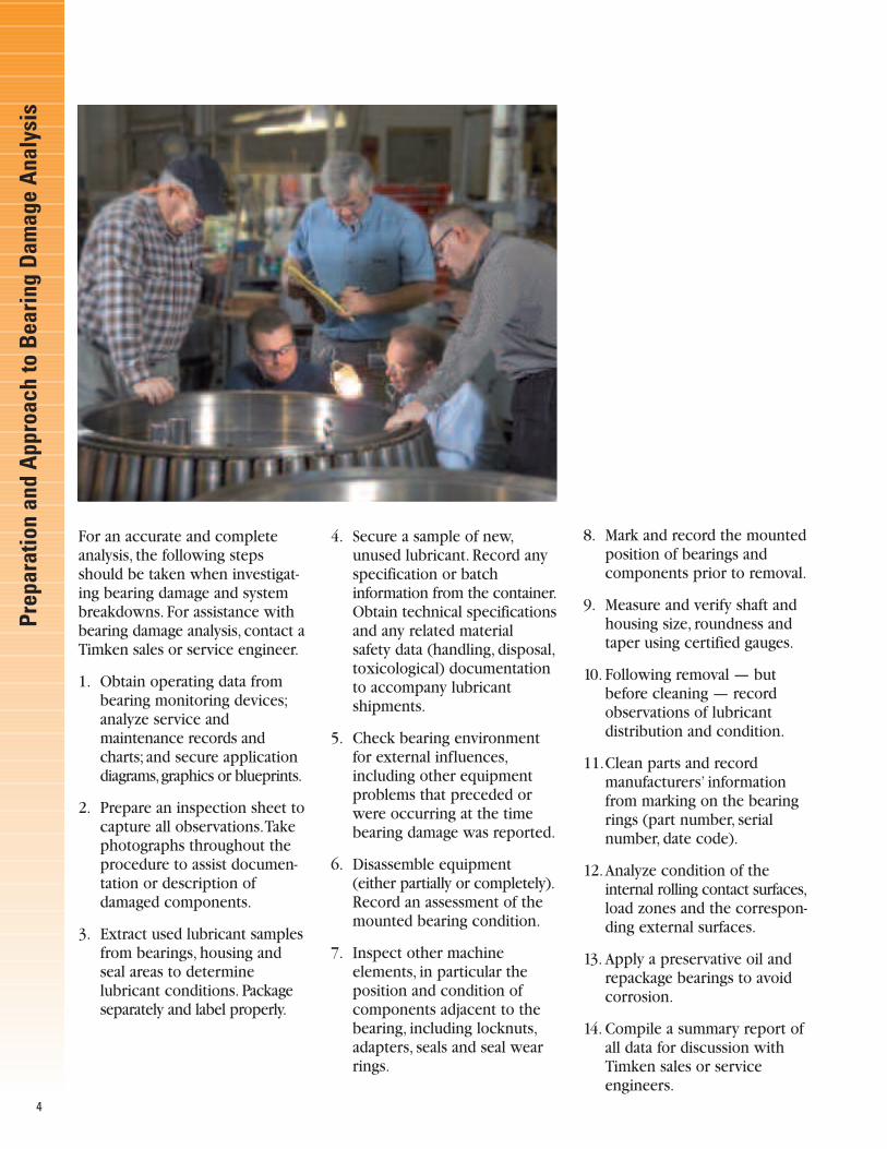
For an accurate and complete analysis, the following stepsshould be taken when investigat-ing bearing damage and systembreakdowns. For assistance withbearing damage analysis, contact aTimken sales or service engineer.
1. Obtain operating data from bearing monitoring devices;analyze service and maintenance records and charts; and secure application diagrams,graphics or blueprints.
2. Prepare an inspection sheet tocapture all observations.Take photographs throughout the procedure to assist documen-tation or description of damaged components.
3. Extract used lubricant samplesfrom bearings, housing and seal areas to determine lubricant conditions. Package separately and label properly.
4. Secure a sample of new,unused lubricant. Record any specification or batch information from the container.Obtain technical specificationsand any related material safety data (handling, disposal,toxicological) documentation to accompany lubricant shipments.
5. Check bearing environment for external influences,including other equipment problems that preceded or were occurring at the time bearing damage was reported.
6. Disassemble equipment (either partially or completely).Record an assessment of themounted bearing condition.
7. Inspect other machine elements, in particular the position and condition of components adjacent to the bearing, including locknuts,adapters, seals and seal wear rings.
8. Mark and record the mounted position of bearings and components prior to removal.
9. Measure and verify shaft and housing size, roundness and taper using certified gauges.
10. Following removal — but before cleaning — record observations of lubricant distribution and condition.
11.Clean parts and recordmanufacturers’ information from marking on the bearing rings (part number, serial number, date code).
12.Analyze condition of the internal rolling contact surfaces,load zones and the correspon-ding external surfaces.
13. Apply a preservative oil and repackage bearings to avoid corrosion.
14. Compile a summary report ofall data for discussion with Timken sales or service engineers.
Prep
arat
ion
and
App
roac
hto
Bea
ring
Dam
age
Ana
lysi
s

Abrasive WearFine foreign material in the bearingcan cause excessive abrasive wear.Sand, fine metal from grinding ormachining, and fine metal or car-bides from gears will wear or lapthe rolling elements and races. Intapered bearings, the roller endsand cone rib will wear to a greaterdegree than the races.This wearwill result in increased end playor internal clearance which canreduce fatigue life and result inmisalignment in the bearing.Abrasive wear can also affect otherparts of the machine in which the bearings are used.The foreignparticles may get in through badlyworn or defective seals. Improperinitial cleaning of housings and parts,ineffective filtration or improperfilter maintenance can allow abrasive particles to accumulate.
Fig. 2: The roller end wear on this spherical bearing was also caused byfine particle contamination.
Fig. 4: Exposure to abrasives and water ina severe environment caused extremewear on this pillow block bearing.
5
Fig. 3: Fine particle contaminationcaused abrasive wear on this taperedroller bearing.
Fig. 1: Fine particle contamination enteredthis spherical roller bearing and generatedwear between the cage surfaces, rollersand races.
Bearing damage can occur as a result of a number of different operatingconditions.Those listed in this section are the most commonly found foranti-friction bearings, including cylindrical, spherical, needle, taperedand ball designs. It is important to remember that proper bearing maintenance and handling practices are critical.
One of the most common sources of trouble in anti-friction bearings is wear and damage caused by foreignparticles. Foreign particle contamination can cause abrasive wear, bruising and grooving, circumferential lining or debris contamination.
TypesofB
earingD
amage
Wear – Foreign Material

6
Wear – Foreign Material
Pitting and Bruising
Hard particles rolling through the bearing may cause pitting andbruising of the rolling elements and races. Metal chips or largeparticles of dirt remaining in improperly cleaned housings can initiate early fatigue damage.
Fig. 8: Hard particles causedcontamination bruising on this sphericalroller bearing.
Fig. 5: Contamination bruising on this needle outer ring race resulted from aharsh environment.
Grooving
Grooving is caused by extremely heavy wear from chips or metalparticles.These contaminants become wedged in the soft cage materialand cause cut grooves in the rolling elements. This condition results inimproper rolling contact geometry and can reduce service life.
Debris Contamination
Common causes of external debris contamination include dirt, sand and environmental particles. Commoncauses of internal debris contamination include wear from gears, splines, seals, clutches, brakes, joints,housings not properly cleaned, and failed or spalled components.These hard particles travel within thelubrication, through the bearing, and eventually bruise (dent) the internal surfaces.The dents form shoulders that act as surface-stress risers, causing premature surface damage and reduced bearing life.
Fig. 9: This photo, taken with a microscope,shows a debris contamination bruise on abearing race. A corresponding surfacemap of the dent is shown below in Fig. 11.
Fig. 7: A tapered roller bearing inner race (cone) with spalling from debriscontamination bruises is shown here.
Fig. 6: Large particle contaminationimbedded into the soft cage material canresult in grooving, as shown here.
Fig. 10: Debris from otherfatigued parts, inadequatesealing or poor maintenancecaused bruising on thistapered roller bearing race. Fig. 11

Fig. 15: This cup has heavy corrosion onthe race. This type of corrosion may onlybe a surface stain without pitting. If thestaining can be cleaned with a fine emerycloth or crocus cloth, the bearing may bereused. If there are pits that cannot becleaned with light polishing, the bearingshould either be discarded or if practical,refurbished.
Fig. 13: Advanced corrosion and pittingon the cone race and rollers makes thisbearing unsuitable for further service.
7
Fig. 14: Heavy water damage is shown onthis ball bearing inner ring and cage.
Fig. 12: This cylindrical bearing inner ringhas etching and corrosion.
Fig. 16: This ball bearing outer race alsodepicts etching and corrosion.
Etching – CorrosionEtching or corrosion is one of the most serious problems encountered in anti-friction bearings.The high degreeof finish on races and rolling elements makes them susceptible to corrosion damage from moisture and water.
Etching is most often caused by condensate collecting in the bearing housing due to temperature changes.The moisture or water oftentimes gets in through damaged, worn or inadequate seals. Improper washing anddrying of bearings when they are removed for inspection can also cause considerable damage. After cleaningand drying or whenever bearings are put into storage, they should be coated with oil or another preservativeand wrapped in a protective paper. Bearings, new or used, should always be stored in a dry area and kept inoriginal packaging to reduce risk of static corrosion appearing before mounting.
Etching – Corrosion

Inadequate LubricationInadequate lubrication is a termused to describe a broad array ofpossible damage conditions, inwhich the lubricant intended forthe bearings was not sufficient toseparate the bearing’s rolling andsliding contact surfaces duringservice. It is very important thatthe proper lubricant amount, type,grade, supply system, viscosity andadditives be properly engineeredfor each bearing system basedupon history, loading, speeds,sealing systems, service conditionsand expected life.Without properconsideration of these factors,less than adequate bearing andapplication performance may be expected.
Fig. 20: Excessive heat generationcaused metal flow in this ball bearinginner ring.
8
Fig. 17: Heat damage on these taperedrollers was caused by metal-to-metalcontact.
Fig. 21: Peeling on the race of this spherical plain bearing was caused bythin lubricant film.
Fig. 22: Micro-spalling or peeling was theresult of thin lubricant film from highloads/low RPM or elevated temperatures.
Inadequate Lubrication
Fig. 18: Total bearing lockup is depictedhere.
Fig. 19: A misshaped inner ring and torncage from inadequate lubrication areshown here.
Bearing damage from inadequatelubrication varies greatly in appear-ance, ranging from very light heatdiscoloration with roller large endscoring (Figure 17), to total bearinglockup with extreme metal flow(Figure 18). It is not uncommon tofind a bearing that has experienceda dry start-up in an application tohave considerable metal flow, yetstill have shiny and polished surfaces.This is because the bearingwill quickly experience heat damagefrom metal-to-metal contact atstart-up, then eventually cool offonce the lubricant makes its wayto the bearings.The bearings maythen attempt to “heal” themselvesby masking the initial metal flowand heat discoloration.
A second, more pronounced
level of damage can occur, whichoften covers up the initial problemand resultant bearing damage.Thisbearing damage typically causeshigh localized heat and metal flowin bearings, thus altering the original bearing geometry and thebearing’s material.Any visible signsof metal tearing, scoring, heat,distortion or geometry alteration(Figures 19 and 20) render bearingsas scrap and they should never beused again.
Careful inspection of all bearings,gears, seals, lubricants and sur-rounding parts often sheds lighton the primary cause of damage.
See the Lubrication ReferenceGuide on page 24 to learn moreabout how lubrication conditionsimpact bearing performance.

9
Fig. 23: High loads resulted in fatiguespalling on this cylindrical roller bearing.
Fig. 26: This ball bearing inner ringdepicts fatigue spalling. The fracture is asecondary damage mode.
Fig. 24: Heavy spalling and fracturing fromhigh loads on this spherical roller bearingare shown here.
Fig. 27: PSO spalling resulted from debrisor raised metal exceeding the lubricantfilm thickness on this tapered roller bearing inner ring.
Fig. 25: Misalignment, deflections orheavy loading on this tapered roller bearing caused GSC spalling.
Fatigue Spalling
Fatigue SpallingSpalling is simply defined as the pitting or flaking away of bearingmaterial. Spalling primarily occurson the races and the rolling ele-ments. It is important to realizethat there are many types of “primary” bearing damage shownthroughout this reference guide,and they will eventually deteriorateinto a secondary damage mode ofspalling.Timken classifies three distinct spalling damage modes:
• Geometric Stress Concentration (GSC) Spalling
This mode is the result of misalignment, deflection, or edgeloading that initiates high stress atlocalized regions of the bearing.The damage occurs at the extremeedges of the race/roller paths. It isusually the end result of machiningproblems with the shaft or the housing, or from high loads.
• Point Surface Origin (PSO) Spalling
This mode is the result of very highand localized stress causing thebearing to prematurely fatigue.Thespalling damage is typically fromnicks,dents,debris, etching and hardparticle contamination in the bear-ing.PSO spalling is the most commonspalling damage, and it oftenappears as arrowhead shaped spalls.
• Inclusion Origin SpallingInclusion Origin Spalling is theresult of bearing material fatigue at localized areas of sub-surface,non-metallic inclusions, followingmillions of load cycles.The damageis observed in the form of localized,elliptically shaped spalls. Bearingsteel cleanness has improved overthe past two decades to the extentthat this type of spalling is seldomencountered.
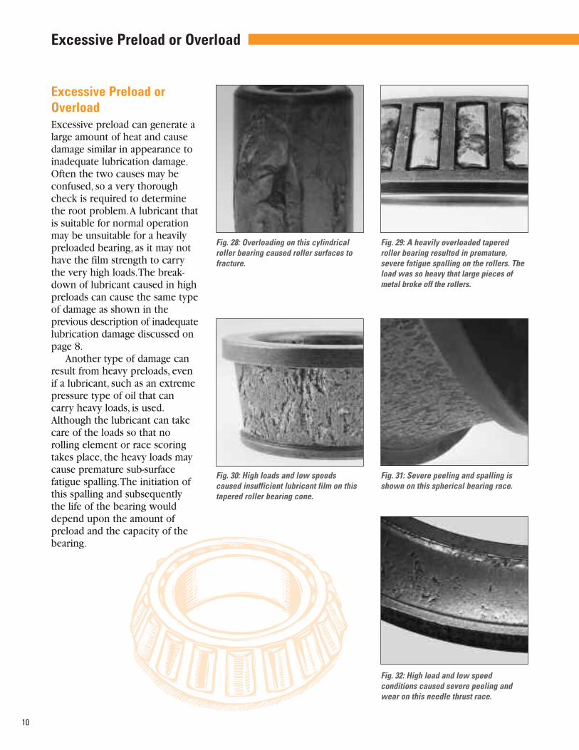
Excessive Preload orOverloadExcessive preload can generate alarge amount of heat and causedamage similar in appearance toinadequate lubrication damage.Often the two causes may beconfused, so a very thoroughcheck is required to determinethe root problem.A lubricant thatis suitable for normal operationmay be unsuitable for a heavilypreloaded bearing, as it may nothave the film strength to carrythe very high loads.The break-down of lubricant caused in highpreloads can cause the same typeof damage as shown in the previous description of inadequatelubrication damage discussed onpage 8.
Another type of damage canresult from heavy preloads, evenif a lubricant, such as an extremepressure type of oil that cancarry heavy loads, is used.Although the lubricant can takecare of the loads so that norolling element or race scoringtakes place, the heavy loads maycause premature sub-surfacefatigue spalling.The initiation ofthis spalling and subsequentlythe life of the bearing woulddepend upon the amount of preload and the capacity of thebearing.
Fig. 29: A heavily overloaded taperedroller bearing resulted in premature,severe fatigue spalling on the rollers. Theload was so heavy that large pieces ofmetal broke off the rollers.
10
Fig. 31: Severe peeling and spalling isshown on this spherical bearing race.
Fig. 32: High load and low speed conditions caused severe peeling and wear on this needle thrust race.
Fig. 28: Overloading on this cylindricalroller bearing caused roller surfaces tofracture.
Fig. 30: High loads and low speedscaused insufficient lubricant film on thistapered roller bearing cone.
Excessive Preload or Overload

11
Fig. 36: This irregular roller path is 180degrees opposite of Fig. 35.
Fig. 37: Geometric Stress Concentrationspalling on the outer race was the resultof a needle bearing installed in an inaccurately machined housing.
Fig. 33: High edge loads causedGeometric Stress Concentration (GSC)spalling on the inner race of this drawncup needle bearing.
Fig. 35: Deflection, inaccurate machiningor wear of bearing seats caused an irregular roller path on this tapered rollerbearing outer ring.
Fig. 34B: Housing Misalignment
Fig. 34A: Shaft Misalignment
Misalignment and Inaccurate Machining of Seats and Shoulders
Misalignment and Inaccurate Machining of Seats andShoulders Misaligned bearings will shorten bearing life.The reduction in servicewill depend on the degree of misalignment.To get full life from thebearing, the seats and shoulders supporting the bearing must be withinspecified limits set by the bearing manufacturer. If the misalignmentexceeds the limits, the load on the bearing will not be distributed alongthe rolling elements and races as intended, but will be concentrated ononly a portion of the rollers or balls and races. In cases of extreme misalignment or off angle, the load will be carried only on the extremeends of the rolling elements and races. A heavy concentration of theload and high stresses at these points will result in early fatigue of themetal.
Causes of misalignment:• Inaccurate machining or wear of housings or shafts
• Deflection from high loads
• Out-of-square backing shoulders on shafts or housings
Fig. 38: The housing bore was machinedwith an improper taper, causing theuneven load distribution and GSC spallingin this cylindrical roller bearing outer ring.

12
Fig. 39: Rough handling or installationdamage resulted in nicks and dents inthis tapered bearing roller.
Fig. 41: A hardened driver caused cup face denting on this tapered roller bearing.
Fig. 40: This spherical roller bearing inner race depicts a fractured toe flange caused bythe use of improper installation tools.
Fig. 42: A hardened driver caused a broken rib on this needle roller bearing.
Handling and Installation Damage
Handling and Installation DamageCare must be taken in handling and assembling bearings so the rolling elements and race surfaces and edgesare not damaged. Deep gouges in the race surface or battered and distorted rolling elements will cause metalto be raised around the gouge or damaged area. High stresses will occur as the rolling elements go overthese surfaces, resulting in premature, localized spalling.The immediate effect of the gouges and deep nickswill be roughness, vibration and noise in the bearing.

Fig. 43: A hardened punch caused indents during assembly.
Fig. 44: Inaccurate housing machining caused metal pick-up and galling on this needleroller bearing.
Fig. 45: Tapered roller spaced nicking was caused by the roller edges hitting the raceduring assembly. These nicks/dents have raised edges that can lead to excessive noise,vibration or act as points of stress concentration.
13

Damaged Bearing Cages or RetainersCareless handling and the use ofimproper tools during bearing installation may cause cage or retainer damage. Cages or retain-ers are usually made of mildsteel, bronze, or brass and can beeasily damaged by improper han-dling or installation, resulting inpremature bearing performanceproblems.
In some applications, fracturedcages or retainers may be causedby environmental and operatingconditions.This type of damageis too complex to cover in thisreference guide. If you experi-ence this problem, contact yourTimken sales or service engineer.
14
Fig. 46: This cage deformation was caused by an improperly installed or dropped bearing.
Fig. 48: Rough handling during maintenance caused a bent bridge on this cylindricalroller bearing cage.
Fig. 49: Poor handling practices caused adeep dent on this spherical roller bearingcage bridge. This damage will result in alack of proper roller rotation, possibleroller skidding, increased temperaturesand decreased life.
Fig. 47: Binding and skewing of these tapered rollers was due to the compression of thecage ring during installation or interference during service.
Damaged Bearing Cages or Retainers
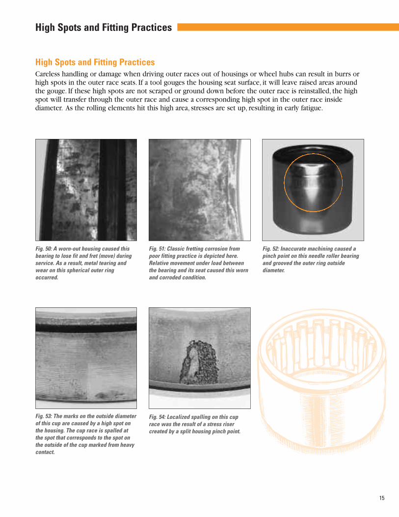
Fig. 54: Localized spalling on this cuprace was the result of a stress riser created by a split housing pinch point.
Fig. 53: The marks on the outside diameterof this cup are caused by a high spot onthe housing. The cup race is spalled atthe spot that corresponds to the spot onthe outside of the cup marked from heavycontact.
High Spots and Fitting PracticesCareless handling or damage when driving outer races out of housings or wheel hubs can result in burrs orhigh spots in the outer race seats. If a tool gouges the housing seat surface, it will leave raised areas aroundthe gouge. If these high spots are not scraped or ground down before the outer race is reinstalled, the highspot will transfer through the outer race and cause a corresponding high spot in the outer race inside diameter. As the rolling elements hit this high area, stresses are set up, resulting in early fatigue.
15
Fig. 50: A worn-out housing caused thisbearing to lose fit and fret (move) duringservice. As a result, metal tearing andwear on this spherical outer ringoccurred.
Fig. 51: Classic fretting corrosion frompoor fitting practice is depicted here.Relative movement under load betweenthe bearing and its seat caused this worn and corroded condition.
Fig. 52: Inaccurate machining caused apinch point on this needle roller bearingand grooved the outer ring outside diameter.
High Spots and Fitting Practices

Improper Fit in Housings or Shafts A manufacturer’s recommended bearing fit should be followed to ensure proper bearing performance.
In general, the bearing race where the rotating load exists should be applied with a press or tight fit.Anexample is a wheel hub where the outer race should be applied with a press fit.The races on a stationaryaxle would normally be applied with a light or loose fit.Where the shaft rotates, the inner race should nor-mally be applied with a press fit and the outer race may be applied with a split fit or even a loose fit,depending on the application.
16
Fig. 58: An out-of-round or oversized shaft caused this fracture on a tapered rollerbearing cone.
Fig. 57: This ball bearing inner ring fracture is a result of being installed on top of a metalcontaminant or raised metal nick.
Fig. 55: A loose cup fit in a rotating wheel hub (typically tight) caused this bearing racedamage.
Fig. 56: This tapered roller bearing cup isfractured as a result of the housing crack-ing during service.
Improper Fit in Housings or Shafts

17
Brinell and Impact DamageImproper mounting practices and/or extremely high operationalimpact or static loads may cause brinelling.
Brinell due to improper mounting is caused where a force is appliedagainst the unmounted race.When mounting a bearing on a shaft with atight fit, pushing the outer race will exert an excessive thrust load andbring the rolling elements into sharp contact with the race, causingbrinell.
In a needle bearing, typical causes are static overload and shock load,although end loading and geometry defects also play a role.
Figure 63A shows improper removal of a bearing off a shaft, while63B illustrates the proper mounting procedure.
Extremely heavy impact loads, which may be short in duration, canresult in brinell of the bearing races and sometime even fracture theraces and rolling elements.
Fig. 64: Shock loading caused brinelldamage on this ball bearing inner ring.
Fig. 60: This inner ring of a sphericalroller bearing shows roller impact damage from shock loading.
Fig. 63B: Proper mounting procedure onarbor press.
Fig. 63A: Incorrect dismounting of bearingon arbor press.
Fig. 59: A heavy impact load on thistapered bearing cup race caused brinelland impact damage. These same indenta-tions are evident on the cone race. This istrue metal deformation and not wear aswith false brinelling. The close-up viewof one of the grooves shows the grindingmarks still in the groove.
Fig. 61: This cylindrical roller bearinginner ring is crushed by an applicationfailure during service.
Fig. 62: Impact during installation causedroller spaced indents on this needle rollerbearing outer ring.
Brinell and Impact Damage

18
False BrinellingFalse brinelling is, as the name implies, not true brinelling or denting. False brinelling is actually frettingwear. It is caused by slight axial movement of the rolling elements while the bearing is stationary. A grooveis worn into the race by the sliding of the rolling element back and forth across the race.Vibration causesthe sliding movement.
There are times when this cannot be prevented, such as when automobiles or other types of equipmentare shipped by rail or truck for relatively long distances. It can also occur during shipment by ocean freight.The vibration present may cause enough movement to produce some of this false brinelling. It can be greatly reduced or eliminated by reducing the potential for relative movement and decreasing the staticweigh present during shipment or storage.
Rolling element bearings also exhibit false brinnelling when used in positions that encounter very smallreversing angular oscillation (less than one complete rotation of the rolling element).
False brinelling can be distinguished from true brinelling by examining the depression or wear area. Falsebrinelling will actually wear away the surface texture whereas the original surface texture will remain in thedepression of a true brinell.
Fig. 66: Wear caused by vibration or relative axial movement between the rollers andraces is depicted here in this tapered roller bearing outer ring.
Fig. 65: False brinelling under extreme vibration caused deep roller spaced wear on the inner raceway of this needle bearing.
False Brinelling

Burns from Electric CurrentArcing, which produces high temperatures at localized points, results when an electric current that passesthrough a bearing is broken at the contact surfaces between the races and rolling elements. Each time thecurrent is broken while passing between the ball or roller and race, a pit is produced on both parts.Eventually fluting develops. As it becomes deeper, noise and vibration result. A high-amperage current, suchas a partial short circuit, will cause a rough, granular appearance. Heavy jolts of high amperage charges will cause more severe damage, resulting in the welding of metal from the race to the ball or roller. Theseprotrusions of metal on the roller will, in turn, cause a crater effect in the race, resulting in bearing noise and vibration.
Causes of arcing include static electricity from charged belts or processes that use calendar rolls, faultywiring, improper grounding, welding, inadequate or defective insulation, loose rotor windings on an electricmotor, and short circuits.
19
Fig. 67: Electric arc pitting or small burns, magnified 10X here, were created by arcs fromimproper electric grounding while the bearing was stationary.
Fig. 69: Magnified by a factor of 10, this fluting, defined as a series of small axial burns,was caused by an electric current passing through the bearing while it was rotating.
Fig. 68: Welding on a machine, while thebearings were rotating, caused electricarc fluting on this spherical roller bearing.
Burns from Electric Current
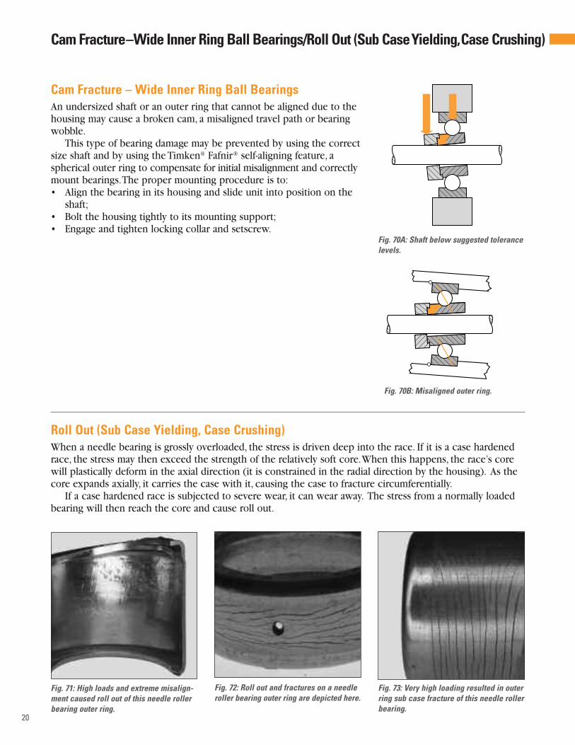
Roll Out (Sub Case Yielding, Case Crushing)When a needle bearing is grossly overloaded, the stress is driven deep into the race. If it is a case hardenedrace, the stress may then exceed the strength of the relatively soft core.When this happens, the race’s corewill plastically deform in the axial direction (it is constrained in the radial direction by the housing). As thecore expands axially, it carries the case with it, causing the case to fracture circumferentially.
If a case hardened race is subjected to severe wear, it can wear away. The stress from a normally loadedbearing will then reach the core and cause roll out.
20
Fig. 70A: Shaft below suggested tolerancelevels.
Fig. 70B: Misaligned outer ring.
Fig. 71: High loads and extreme misalign-ment caused roll out of this needle rollerbearing outer ring.
Fig. 73: Very high loading resulted in outerring sub case fracture of this needle rollerbearing.
Fig. 72: Roll out and fractures on a needleroller bearing outer ring are depicted here.
Cam Fracture – Wide Inner Ring Ball BearingsAn undersized shaft or an outer ring that cannot be aligned due to thehousing may cause a broken cam, a misaligned travel path or bearingwobble.
This type of bearing damage may be prevented by using the correctsize shaft and by using the Timken® Fafnir® self-aligning feature, aspherical outer ring to compensate for initial misalignment and correctlymount bearings.The proper mounting procedure is to:• Align the bearing in its housing and slide unit into position on the
shaft;• Bolt the housing tightly to its mounting support;• Engage and tighten locking collar and setscrew.
Cam Fracture–Wide Inner Ring Ball Bearings/Roll Out (Sub CaseYielding,Case Crushing)

Rollers Locked in PlaceBearing failure may also be causedif the pilot in the tool used toinstall the full complement bearingdoes not have a functional balldetent. In shipping, a full comple-ment bearing’s rollers often settleinto a slightly skewed position. Ifthe bearing’s rollers are not alignedprior to pressing the bearing intothe housing, the rollers will lockinto place at installation.The shaftthen skids on the locked rollersresulting in smeared flats. Thebearing components may beseverely discolored (black or blue).
Fig. 74: When the bearing was installedusing a pusher without a ball detent toalign the rollers, the rollers locked inplace as the cup shrunk during installa-tion. The shaft then spun against thelocked rollers. (See Fig. 75 right.)
Fig. 75: Aninstallation toolwith 15 degreebackangle, for drawn cupbearing installation isshown here.
C
15°
A
D
E
B
StampedendofbearingGenerous
chamferor roundingforeasy bearinginstallation
Fig. 76: This needle drawn cup bearingwas installed with an improper tool, damaging the lip. Lip damage this severemay lock up the bearing. (See Fig. 75above.)
Bearing Stamping Lip Fractured OffA bearing’s lip may be fractured off if the tool used to install the bearing lacks the required 15 degree backangle.Without this backan-gle, the installation force is directed through the lip of the cup and will fracture it. Often the lip is only cracked at installation and thenbreaks in service.With the proper 15 degree backangle, the installationforce is directed through the cup’s wall, eliminating the possibility offracturing the cup’s lip.
21
Rollers Locked in Place/Bearing Stamping Lip Fractured Off
Stamped endof bearing
Ball detent
Generouschamfer or rounding for easybearinginstallation
Fig. 75 Key: A = 1/64 in. (0.4 mm) less than housing boreB = .003 in. (0.08 mm) less than shaft diameterC = distance bearing will be inset into housing;
minimum of .008 in. (0.2 mm)D = pilot length should be length of bearing
less 1/32 in. (0.8 mm)E = Approximately one half of D

We have illustrated many waysthat bearings might get damaged.What can you expect from a bearing that is properly handled,installed, adjusted, lubricated andmaintained? The following sectionprovides some background onbearing fatigue and service life.
The theoretical bearing lifeexpectancy of a group of bearingscan be calculated from the operat-ing conditions and the bearingload rating, based on materialfatigue. These calculations mustassume that the bearings are correctly mounted, adjusted,lubricated and otherwise properly handled.
Bearing Fatigue LifeBearings are laboratory examinedand tested to verify the basis for
bearing load ratings, and to driveenhancements in the performanceof parts from global sources. L10life is defined as the theoreticalpredicted life that 90 percent ofa sufficiently large group of bear-ings would achieve or exceedbefore an area of spalling orrolling contact surface fatiguedamage reaches the defined 6mm2 (0.01 inch2) size criterion.
If handled, mounted, adjusted,lubricated, maintained and used inthe right way, bearings have thebest chance of reaching their predicted life.
Figure 77 shows the typical distribution of theoretical bearingsurvival at the respective lives.Although tapered roller bearingswere used in this illustration, thesame general distribution holds truefor other rolling element designs.
Life in Multiples of Rating Life, L10
Prob
abili
tyof
Failu
reDu
ring
aSp
ecifi
edLi
feIn
terv
al
0 1
20
15
10
5
0 2 3 4 5 6 7 8 9 10 11 12 13 14
Rated LifeL10
Fig. 77: Theoretical life frequency distribution of a statistically significant group of apparently identical tapered rolling bearings operating under similar laboratory conditions. The same general distribution can be made for other rolling element bearing designs.
22
Und
erst
andi
ngB
eari
ngLi
fe

Bearing Operating Setting
Light preloadL10 life
PRELOAD
0
High clearance
Heavy preload Zero clearance
CLEARANCE
Bearing Service LifeBearing service life is dependenton many factors other than the calculated L10 fatigue life.Depending on the applicationrequirements, the actual servicelife can vary greatly. For example,a machine tool spindle bearingmay be unfit for further servicedue to minor wear that affectsspindle accuracy. In contrast, arolling mill roll neck bearing mayprovide satisfactory service lifeeven if the bearing has developedspalling damage, provided thespalls are properly repaired in atimely fashion.
Reduced service life can becaused either individually or byany combination of:
• Faulty mounting
• Improper adjustment
• Insufficient lubrication
• Contamination
• Improper or abusive handling
• Poor housing support
• High static misalignment or shaft and housing deflection
• Poor or inconsistent maintenance practices
Fig. 78: Bearing life vs. bearing operating setting
23
The life of your bearing isdependent on the load zoneobtained under operating conditions. Generally speaking, thegreater the load zone, the longerthe life of the bearing under stabilized operating conditions.Figure 78 illustrates this relation-ship for tapered roller bearings;other roller bearings with radialloads would have a similar performance relationship.

24
OverfillingOverfilling a bearing with too much grease or oil can cause excess churning during operation and high temperatures, resulting in overheating and excess grease purging* (leaking). Overheating occurs because the heat generated cannot dissipate correctly, continually building until damage occurs. As the operating temperature of the bearing rises, the oxidation (breakdown) rate of the grease sharply increases — doublingevery 18 F degrees (10 C degrees).
*NOTE: During initial start-up, it is common for a properly lubricated bearing to purge a small amount of grease. A slight grease purge is often recommendedby original equipment manufacturers, as it acts as a barrier seal to help keep out external debris contamination (Figure 80). Always follow original equip-ment manufacturers’ recommendations regarding grease purging and correct replenishment amounts.
An overfilled bearing may also purge grease during initial start-up. However, over time and as temperature rises, excess grease will continue to purgefrom an overfilled bearing and have a darkened color (Figure 79).
Fig. 80: ‘Clean’ grease slightly purging(leaking) from a bearing during initial start-up is generally acceptable. The grease iswet and evenly purged. If this slight purgeis not causing any problems, leave it aloneas it is an effective barrier seal.
Fig. 79: This petri dish contains heavilyoxidized grease, which purged from anoverfilled bearing. Grease undergoingheavy oxidation often has a very distin-guishable black color and burned odor.In addition, it gets stiffer in consistency.
Fig. 81: Grease removed from an underfilledbearing shows shiny bearing metal debris.
UnderfillingUnderfilling a bearing with grease can also have adverse consequences.As in overfilling, heat can be generated but for different reasons. Whenthe grease amount is low, a grease starvation condition may be created,causing heat generation or excessive metal wear during operation. If abearing suddenly becomes noisy and/or the temperature increases,excessive wear may be taking place.
Factors that Impact Lubrication Performance
As noted on page 8, the life of a Timken® bearing depends to a great extent on the proper lubrication of thebearing. Lubricants aid in carrying away heat, protecting bearing surfaces from corrosion, and reducing friction.
A very high percentage of all bearing damage can be attributed to inadequate lubrication. Although a verybroad term, inadequate lubrication can be classified into eight basic categories:• Overfilling • Underfilling • Incorrect grease • Mixing greases • Incorrect lubrication systems
and intervals • Worn-out grease • Water contamination • Debris contaminationLu
bric
atio
nRe
fere
nce
Gui
deFactors that Impact Lubrication Performance

25
Fig. 82: This cylindrical roller flattened asa result of skidding. Fig. 83: Peeling (micro-spalling) on this
needle thrust bearing inner race was dueto a thin lubricant film from elevated temperatures. Fig. 84: Micro-spalling in a tapered roller
bearing outer race (bottom) and innerrace (top) was due to thin lubricant filmresulting from elevated temperature.
Incorrect GreaseThe base oil in a particular grease may have a different thickness (viscosity) than what is recommended foryour application. If the base oil viscosity is too heavy, the rolling elements may have difficulty in pushingthrough the grease and begin to skid (Figure 82). If this occurs, excessive grease oxidation (breakdown)(Figure 83) may cause premature grease degeneration and excessive wear of bearing components. If the viscosity is too light, peeling (micro-spalling) and wear (Figure 84) may result due to thin lubricant film fromelevated temperatures. In addition, the additives contained in a particular grease may be inappropriate oreven incompatible with surrounding components in your system.
Fig. 85: Grease A and Grease B are notcompatible. When mixed together theybecome lumpy, discolored and hard incomposition (Grease C).
A B
C
Mixing GreasesA bearing may be running well with the correct grease. However,while performing routine maintenance, a technician may decide tolubricate the bearing with a different type of grease. If the greases arenot compatible, or are an incorrect consistency, the grease mixture will do one of two things: 1) soften and leak out of the bearing due togrease thickener incompatibility, or 2) become lumpy, discolored andhard in composition (Figure 85).
Fig. 86: Grease is a precise combinationof additives, oil and thickener.
Fig. 87: The above photo shows the samegrease at three stages (from left to right):1) new grease, 2) heavily oxidized grease,and 3) worn-out (failed) grease where the thickener and additives have decomposed and the oil has broken down.
Worn-Out GreaseGrease is a precise combinationof additives, oil and thickener(Figure 86). Grease acts like asponge to retain and release the oil. As a result of time andtemperature conditions, the oilrelease properties can becomedepleted.When this occurs, thegrease is worn-out (Figure 87).

26
Fig. 91
Fig. 92: To performa crackle test, firstput the grease sample on a pieceof aluminum foil.
Fig. 93: A crackletest determines thepresence of waterin grease.
Fig. 90A tapered roller bearing (Fig. 90) and aball bearing outer race and balls (Fig. 91)are rusting with pitting and corrosionfrom moisture/water exposure. This con-dition is referred to as etching.
Water ContaminationFigure 89 shows the effect of water on grease by comparing fresh grease to a grease emulsified with 30 percentwater. The fresh grease is smooth and buttery compared to the water laden grease, which is milky white inappearance. As little as one percent water in grease can have a significant impact on bearing life.
Incorrect Lubrication Systems and Intervals Maintaining correct bearing lubrication systems and intervals is criticalto help prevent premature wear of bearing components.
If maintenance schedules are not followed (Figure 88), lubricationmay deteriorate through excessive oxidation. Figure 79 shows excessivebearing grease oxidation. Fig. 88: A technician records key bearing
lubrication data on a maintenance sheet.
Quick & Easy Field Test to Determine Water in GreaseAn easy, non-quantified method of determining the presence of water in grease is known as the “crackle test.” To perform this test, place a sam-ple of grease on a piece of aluminum foil (Figure 92) and put a flameunder the foil (Figure 93). If the grease melts and lightly smokes, thepresence of water is minimal. However, if the grease crackles, sizzlesand/or pops, the grease contains a considerable amount of water.
Fig. 89: The effect of water on grease isdepicted here.
Fresh grease Grease with 30 percent water

To avoid the generation ofheat, the bearing must not beovergreased. The required quanti-ty of grease is based on the freevolume of the bearing calculatedas follows:
V = ≈π/4 (D2 – d2) (T) – M/A
Where:V = free volume in the bearing
(cm3 – inch3)D = outer race O.D. (cm – inch)d = inner race bore (cm – inch)T = overall width (cm – inch)M = bearing weight (kg – lb)A = average steel density
7.8 x 10⁻³ kg/cm3
0.2833 lb/inch3
π = 3.1416
Grease should be uniformly distributed over the rollers,raceway, rigs and cages. Specialrecommendations apply to sealedbearing assemblies. ContactTimken for more information.
Consult the original equipment manufacturer for all lubricant information.
Grease Compatibility Chart
n = Best Choice
n = Compatible
n = Borderline
n = Incompatible
Aluminum Complex
Timken Food Safe
Barium Complex
Calcium Stearate
Calcium 12 Hydroxy
Calcium Complex
Calcium Sulfonate
Timken Premium MillTimken Heavy Duty Moly
Clay Non-Soap
Lithium Stearate
Lithium 12 Hydroxy
Lithium Complex
Polyurea Conventional
Polyurea Shear Stable
Timken Multi-Use
Timken All PurposeTimken Premium Synthetic
Timken High Speed
Timken Pillow Block
AlC
ompl
ex
Ba
Com
plex
CaSt
eara
te
Ca12
Hyd
roxy
CaCo
mpl
ex
CaSu
lfona
te
Clay
Non
-Soa
p
LiSt
eara
te
Li12
Hyd
roxy
LiCo
mpl
ex
Poly
urea
Poly
urea
SS
Lubrication Guidelines – Required Grease Quantity
27
Lubrication Guidelines

Abrasive WearUsually occurs when foreign
particles cut the bearing surfaces.
Adhesive WearCaused by metal-to-metal contact,
resulting in scuffing or scoring of thebearing surfaces.
Angular Contact Ball BearingBall bearing whose internal
clearance and race location result inpredetermined angle of contact.
Axial Internal ClearanceIn ball or roller bearing assembly,
total maximum possible movementparallel to bearing axis of inner ringin relation to outer ring.Also calledbearing end play.
Axial LoadLoad acting in direction parallel
with bearing axis.Also known as“thrust.”
BrinellingA dent or depression in the
bearing raceway due to extremelyhigh impact or static loads.
Brinelling – FalseWear grooves in the raceway
caused by minute movement or vibration of the rolling elementswhile the bearing is stationary.
Bruising The denting or plastic indentation
in the raceways and rolling elementsdue to the contamination of foreignparticles in the bearing.
End Play – Internal ClearanceThe relative movement of the
inner race and rolling elements to the outer race. In single ball and cylindrical bearing, it is the radialmovement or the internal clearance.In a tapered bearing it is the axialmovement to the two cone assemblies relative to the cups.
Etching – CorrosionUsually caused by moisture or
water contamination and can varyfrom light staining to deep pitting.
FatigueThe fracture and breaking away of
metal in the form of a spall. Generally,there are three modes of contactfatigue recognized:• Inclusion origin• Geometric stress concentration• Point surface origin
Fillet RadiusShaft or housing corner dimension
which bearing corner must clear.
Fixed Bearing Bearing which positions shaft
against axial movement in both directions.
Floating BearingBearing so designed or mounted
as to permit axial displacementbetween shaft and housing.
FlutingElectro-etching on both the inner
and outer ring.
Fretting CorrosionUsually occurs on the bores,
outside diameters (O.D.) and faces ofbearing races due to minute movement of these surfaces and theshaft or housing. Red or black oxideof iron is usually evident.
Housing FitAmount of interference or
clearance between bearing outsidesurface and housing bearing seat.
LifeThe theoretical bearing life
expectancy of a group of bearingscan be calculated from the operatingconditions and the bearing load rating, based on material fatigue.These calculations must assume thatthe bearings are correctly mounted,adjusted, lubricated and otherwiseproperly handled.
MisalignmentA bearing mounted condition
whereby the centerline of the innerrace or cone is not aligned with thecenterline of the outer race or cup.Lack of parallelism between axis ofrotating member and stationary
member. Some of the causes of misalignment are, machining errorsof the housing/shaft, deflection due to high loads, and excessiveoperating clearances.
PreloadThe absence of end play or
internal clearance.All of the rollingelements are in contact or in compression with the inner andouter races or cups and cones.Internal load on the rolling elementsof bearing, which is the result ofmounting conditions or design. Canbe intentional or unintentional.
Radial Internal ClearanceIn ball or roller bearing assembly,
total maximum possible movementperpendicular to bearing axis ofinner ring in relation to outer ring.Also called radial play or diametricalclearance.
Radial LoadLoad acting in direction
perpendicular with bearing axis.
Rating LifeL10 of group of apparently
identical bearings is predicted life in millions of revolutions that 90percent of group will complete orexceed.
ScoringCaused by metal-to-metal
contact, resulting in the removal andtransfer of metal from one compo-nent of a bearing to another.Variousdegrees of scoring can be describedas scuffing, smearing, sliding, gallingor any other sliding motion.
Shaft FitAmount of interference or
clearance between bearing insidediameter and shaft bearing seat outside diameter.
Spalling – FlakingA breaking away of metal on the
raceway or rolling elements in flakeor scale-like particles.
Glo
ssar
y
28
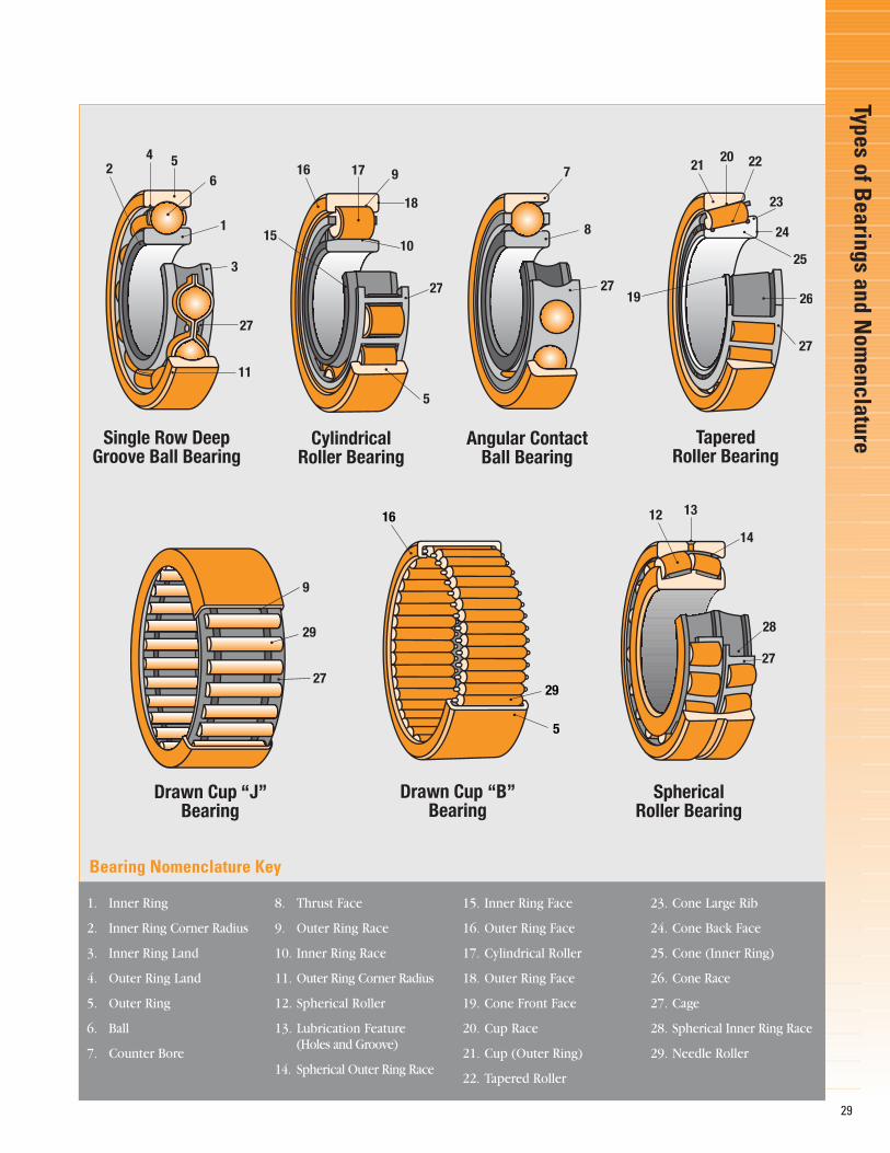
TypesofB
earingsand
Nom
enclature
29
1. Inner Ring
2. Inner Ring Corner Radius
3. Inner Ring Land
4. Outer Ring Land
5. Outer Ring
6. Ball
7. Counter Bore
8. Thrust Face
9. Outer Ring Race
10. Inner Ring Race
11. Outer Ring Corner Radius
12. Spherical Roller
13. Lubrication Feature (Holes and Groove)
14. Spherical Outer Ring Race
15. Inner Ring Face
16. Outer Ring Face
17. Cylindrical Roller
18. Outer Ring Face
19. Cone Front Face
20. Cup Race
21. Cup (Outer Ring)
22. Tapered Roller
23. Cone Large Rib
24. Cone Back Face
25. Cone (Inner Ring)
26. Cone Race
27. Cage
28. Spherical Inner Ring Race
29. Needle Roller
Bearing Nomenclature Key
Single Row DeepGroove Ball Bearing
42 5
6
1
3
27
11
Angular ContactBall Bearing
7
8
27
TaperedRoller Bearing
2120
19
22
23
24
25
26
27
CylindricalRoller Bearing
16
15
17
18
9
27
10
5
Drawn Cup “J”Bearing
29
27
9
SphericalRoller Bearing
12 13
14
28
27
Drawn Cup “B”Bearing
16
29
5

Speed CapabilityGuidelinesThe usual measure of the speedof a bearing is the circumferen-tial velocity of the midpoint ofthe inner race large end rib.Thismay be calculated as:
Fig. 95: Here is a summary of guidelines relating to speed andtemperature for tapered roller bearings. There are no clear-cutspeed limitations for bearings regardless of the bearing designor lubrication systems. The Timken Company recommends thattesting be performed for all new high-speed applications,regardless of bearing design.
Inner Race Rib Speed
Special high speed bearings with circulating oil
Oil jets
Oil-mist/oil-air
Circulating oil
Oil level
Grease
0 10 20 30 40 50 100 200 m/s0 2000 4000 6000 8000 10 000 20 000 40 000 ft/min
Typical industry experience indicates no problems under ordinary circumstances.
Industry experience indicates testing may be required to optimize system.
Applies only for non-continuous process.
Speed Capability Guidelines
Speed capability guidelines for various types of lubrication systems
Tape
red
Rolle
rBea
ring
Spee
dCa
pabi
lity
Gui
delin
es
30
Rib speed:Vr = πDmn/60 000 (m/s) Vr = πDmn/12 (ft/min)
Where:Dm = Inner race rib diameter (mm, in)n = Bearing speed (rev/min)π = 3.1416
Fig. 94: The inner race rib diameter canbe scaled from a drawing or can beapproximated as the average of thebearing inner and outer diameter.
Inner race rib diameterDm

31
ConversionEquivalents
forU.S.and
Metric
Measurem
ents
Conversion Equivalents for U.S. and Metric Measurements
Physical Quantity When you know Multiply by To get an equivalent in
Length inch (in.) 25.4 millimetre (mm)inch (in.) 2.54 centimetre (cm)miles 1.609 kilometre (km)millimetre (mm) 0.03937 inch (in.)centimetre (cm) 0.3937 inch (in.)kilometre (km) 0.6214 mileskilometre (km) 3280.8 foot (ft.)
Area square inch (sq. in.) 645.2 square millimetre (mm2)square inch (sq. in.) 6.4516 square centimetre (cm2)square millimetre (mm2) 0.00155 square inch (sq. in.)square centimetre (cm2) 0.155 square inch (sq. in.)
Volume inch3 (in.3) 16.387 cubic centimetre (cc, cm3)cubic centimetre (cc, cm3) 0.061 inch3 (in.3)litre (1 1 = 1000 cc, cm3) 61.0237 inch3 (in.3)
Fluid quart, U.S. (qt.) 0.946 litre (l)Volume gallon, U.S. 3.785 litre (l)
litre (l) 1.057 quart, U.S. (qt.)litre (l) 0.264 gallon, U.S. litre (l) 0.22 gallon, U.K.gallon, U.K. 4.546 litre (l)
Weight/Mass pound (lb.) 0.4536 kilogram (kg)ounce (oz.) 28.35 gram (gm)kilogram (kg) 2.2046 pound (lb.)gram (gm) 0.035 ounce (oz.)metric ton (1 t = 1000 kg) 2204.6 pound (lb.)
Force ounce-force 0.278 newton (N)pound-force (lbf) 4.448 newton (N)newton (N) 3.5969 ounce-forcenewton (N) 0.2248 pound-force (lbf)
Engine foot-pound (ft.-lb.) 1.3558 newton-metre (Nm)Torque newton-metre (Nm) 0.7376 foot-pound (ft.-lb.)
Hardware foot-pound (ft.-lb.) 0.138 kilogram-metre (kg-m)Torque foot-pound (ft.-lb.) 1.3558 newton-metre (Nm)
inch-pound (in. lbf) 0.113 newton-metre (Nm)kilogram-metre (kg-m) 7.23 foot-pound (ft.-lb.)newton-metre (Nm) 0.7376 foot-pound (ft.-lb.)kilogram-metre (kg-m) 9.807 newton-metre (Nm)newton-metre (Nm) 0.102 kilogram-metre (kg-m)
Pressure pound/inch2 (PSI) 6.895 kilopascal (kPa)kilopascal (kPa) 0.145 pound/inch2 (PSI)
Power horsepower (hp) 0.746 kilowatt (kW)kilowatt (kW) 1.341 horsepower (hp)
Velocity miles per hour (mph) 1.609 kilometres per hour (km/h)kilometres per hour (km/h) 0.621 miles per hour (mph)
Fuel miles per gallon (mpg) 0.425 kilometres per liter (km/l)Usage kilometres per litre (km/l) 2.353 miles per gallon (mpg)

Conversion Chart Showing Millimetre, Fractional and Decimal Inch SizesFrac- Dec. Milli- Frac- Dec. Milli- Frac- Dec. Milli- Frac- Dec. Milli- Frac- Dec. Milli-tional Equiv. metre tional Equiv. metre tional Equiv. metre tional Equiv. metre tional Equiv. metre
.0039 .1 .0689 1.75 .1570 .... .2677 6.8 27/64” .4219 10.72
.0059 .15 .0700 .... .1575 4.0 .2716 6.9 .4330 11.0
.0079 .2 .0709 1.8 .1590 .... .2720 .... 7/16” .4375 11.11
.0098 .25 .0728 1.85 .1610 ... .2756 7.0 .4528 11.5
.0118 .3 .0730 ... .1614 4.1 .2770 ... 29/64” .4531 11.51
.0135 ... .0748 1.9 .1654 4.2 .2795 7.1 15/32” .4687 11.91
.0138 .35 .0760 ... .1660 ... .2811 ... .4724 12.0
.0145 ... .0767 1.95 .1673 4.25 9/32” .2812 7.14 31/64” .4843 12.301/64” .0156 .39 5/64” .0781 1.98 .1693 4.3 .2835 7.2 .4921 12.5
.0157 .4 .0785 ... .1695 ... .2854 7.25 1/2” .5000 12.7
.0160 ... .0787 2.0 11/64” .1719 4.37 .2874 7.3 .5118 13.0
.0177 .45 .0807 2.05 .1730 ... .2900 ... 33/64” .5156 13.10
.0180 ... .0810 ... .1732 4.4 .2913 7.4 17/32” .5312 13.49
.0197 .5 .0820 ... .1770 ... .2950 ... .5315 13.5
.0200 ... .0827 2.1 .1771 4.5 .2953 7.5 35/64” .5469 13.89
.0210 ... .0846 2.15 .1800 ... 19/64” .2968 7.54 .5512 14.0
.0217 .55 .0860 ... .1811 4.6 .2992 7.6 9/16” .5625 14.29
.0225 ... .0866 2.2 .1820 ... .3020 ... .5709 14.5
.0236 .6 .0885 2.25 .1850 4.7 .3031 7.7 37/64” .5781 14.68
.0240 ... .0890 ... .1870 4.75 .3051 7.75 .5906 15.0
.0250 ... .0905 2.3 3/16” .1875 4.76 .3071 7.8 19/32” .5937 15.08
.0256 .65 .0925 2.35 .1890 4.8 .3110 7.9 39/64” .6094 15.48
.0260 ... .0935 ... .1910 ... 5/16” .3125 7.94 .6102 15.5
.0280 ... 3/32” .0937 2.38 .1929 4.9 .3150 8.0 5/8” .6250 15.88
.0276 .7 .0945 2.4 .1935 ... .3160 ... .6299 16.0
.0292 ... .0960 ... .1960 ... .3189 8.1 41/64” .6406 16.27
.0295 .75 .0964 2.45 .1968 5.0 .3228 8.2 .6496 16.5
.0310 ... .0980 ... .1990 ... .3230 ... 21/32” .6562 16.671/32” .0312 .79 .0984 2.5 .2008 5.1 .3248 8.25 .6693 17.0
.0315 .8 .0995 ... .2010 ... .3268 8.3 43/64” .6719 17.06
.0320 ... .1015 ... 13/64” .2031 5.16 21/64” .3281 8.33 11/16” .6875 17.46
.0330 ... .1024 2.6 .2040 ... .3307 8.4 .6890 17.5
.0335 .85 .1040 ... .2047 5.2 .3320 ... 45/64” .7031 17.86
.0350 ... .1063 2.7 .2055 ... .3346 8.5 .7087 18.0
.0354 .9 .1065 ... .2067 5.25 .3386 8.6 23/32” .7187 18.26
.0360 ... .1082 2.75 .2086 5.3 .3390 ... .7283 18.5
.0370 ... 7/64” .1094 2.78 .2090 ... .3425 8.7 47/64” .7344 18.65
.0374 .95 .1100 ... .2126 5.4 11/32” .3437 8.73 .7480 19.0
.0380 ... .1102 2.8 .2130 ... .3445 8.75 3/4” .7500 19.05
.0390 ... .1110 ... .2165 5.5 .3465 8.8 49/64” .7656 19.45
.0394 1.0 .1130 ... 7/32” .2187 5.56 .3480 ... .7677 19.5
.0400 ... .1141 2.9 .2205 5.6 .3504 8.9 25/32” .7812 19.84
.0410 ... .1160 ... .2210 ... .3543 9.0 .7874 20.0
.0413 1.05 .1181 3.0 .2244 5.7 .3580 ... 51/64” .7969 20.24
.0420 ... .1200 ... .2263 5.75 .3583 9.1 .8071 20.5
.0430 ... .1220 3.1 .2280 ... 23/64” .3594 9.13 13/16” .8125 20.64
.0433 1.1 1/8” .1250 3.18 .2283 5.8 .3622 9.2 .8268 21.0
.0452 1.15 .1260 3.2 .2323 5.9 .3641 9.25 53/64” .8281 21.03
.0465 ... .1279 3.25 .2340 ... .3661 9.3 27/32” .8437 21.433/64” .0469 1.19 .1285 ... 15/64” .2344 5.95 .3680 ... .8465 21.5
.0472 1.2 .1299 3.3 .2362 6.0 .3701 9.4 55/64” .8594 21.83
.0492 1.25 .1338 3.4 .2380 ... .3740 9.5 .8661 22.0
.0512 1.3 .1360 ... .2401 6.1 3/8” .3750 9.53 7/8” .8750 22.23
.0520 ... .1378 3.5 .2420 ... .3770 ... .8858 22.5
.0531 1.35 .1405 ... .2441 6.2 .3780 9.6 57/64” .8906 22.62
.0550 ... 9/64” .1406 3.57 .2460 6.25 .3819 9.7 .9055 23.0
.0551 1.4 .1417 3.6 .2480 6.3 .3838 9.75 29/32” .9062 23.02
.0570 1.45 .1440 ... 1/4” .2500 6.35 .3858 9.8 59/64” .9219 23.42
.0591 1.5 .1457 3.7 .2520 6.4 .3860 ... .9252 23.5
.0595 ... .1470 ... .2559 6.5 .3898 9.9 15/16” .9375 23.81
.0610 1.55 .1476 3.75 .2570 ... 25/64” .3906 9.92 .9449 24.01/16” .0625 1.59 .1495 ... .2598 6.6 .3937 10.0 61/64” .9531 24.21
.0629 1.6 .1496 3.8 .2610 ... .3970 ... .9646 24.5
.0635 ... .1520 ... .2638 6.7 .4040 ... 31/32” .9687 24.61
.0649 1.65 .1535 3.9 17/64” .2656 6.75 13/32” .4062 10.32 .9843 25.0
.0669 1.7 .1540 ... .2657 6.75 .4130 ... 63/64” .9844 25.03
.0670 ... 5/32” .1562 3.97 .2660 ... .4134 10.5 1” 1.000 25.4
32
Conv
ersi
onCh
artS
how
ing
Mill
imet
re,F
ract
iona
land
Dec
imal
Inch
Size
s

Temperature Conversion TableThis conversion table can be used to convert temperature to Celsius (°C) or to Fahrenheit (°F). The center
column is the base temperature. If you want to convert from °F to °C, you would look up the number in the center column and the number in the left column would show the conversion in °C. To convert °C to °F, you would look upthe base number and the conversion to °F is shown in the right column.
As an example, to find the °F for 100°C, look up 100 in the base temperature column. The column to the rightshows +212°F as the conversion.The shaded portions of the chart represent negative values.
BASE BASE BASE BASE BASETEMP. TEMP. TEMP. TEMP. TEMP.
°C °F or °C °F °C °F or °C °F °C °F or °C °F °C °F or °C °F °C °F or °C °F-73.33 -100 -148.0 1.11 30 86.0 40.56 105 221.0 148.89 300 572 357.22 675 124770.55 95 139.0 0.56 31 87.8 41.11 106 222.8 151.67 305 581 360.00 680 125667.78 90 130.0 0.00 32 89.6 41.67 107 224.6 154.44 310 590 362.78 685 126565.00 85 121.0 +0.56 33 91.4 42.22 108 226.4 157.22 315 599 365.56 690 127462.22 80 112.0 1.11 34 93.2 42.78 109 228.2 160.00 320 608 368.34 695 128359.44 75 103.0 1.67 35 95.0 43.33 110 230.0 162.78 325 617 371.11 700 129256.67 70 94.0 2.22 36 96.8 43.89 111 231.8 165.56 330 626 373.89 705 130153.89 65 85.0 2.78 37 98.6 44.44 112 233.6 168.33 335 635 376.67 710 131051.11 60 76.0 3.33 38 100.4 45.00 113 235.4 171.11 340 644 379.44 715 131948.33 55 67.0 3.89 39 102.2 45.56 114 237.2 173.89 345 653 382.22 720 132845.56 50 58.0 4.44 40 104.0 46.11 115 239.0 176.67 350 662 385.00 725 133744.44 48 54.4 5.00 41 105.8 46.67 116 240.8 179.44 355 671 387.78 730 134643.33 46 50.8 5.56 42 107.6 47.22 117 242.6 182.22 360 680 390.56 735 135542.22 44 47.2 6.11 43 109.4 47.78 118 244.4 185.00 365 689 393.33 740 136441.11 42 43.6 6.67 44 111.2 48.33 119 246.2 187.78 370 698 396.11 745 137340.00 40 40.0 7.22 45 113.0 48.87 120 248.0 190.56 375 707 398.89 750 138238.89 38 36.4 7.78 46 114.8 49.44 121 249.8 193.33 380 716 401.67 755 139137.78 36 32.8 8.33 47 116.6 50.00 122 251.6 196.11 385 725 404.44 760 140036.67 34 29.2 8.89 48 118.4 50.56 123 253.4 198.89 390 734 407.22 765 140935.56 32 25.6 9.44 49 120.2 51.11 124 255.2 201.67 395 743 410.00 770 141834.44 30 22.0 10.00 50 122.0 51.67 125 257.0 204.44 400 752 412.78 775 142733.33 28 18.4 10.56 51 123.8 52.22 126 258.8 207.22 405 761 415.56 780 143632.22 26 14.8 11.11 52 125.6 52.78 127 260.6 210.00 410 770 418.33 785 144531.11 24 11.2 11.67 53 127.4 53.33 128 262.4 212.78 415 779 421.11 790 145430.00 22 7.6 12.22 54 129.2 53.89 129 264.2 215.56 420 788 423.89 795 146328.89 20 4.0 12.78 55 131.0 54.44 130 266.0 218.33 425 797 426.67 800 147228.33 19 2.2 13.33 56 132.8 55.00 131 267.8 221.11 430 806 429.44 805 148127.78 18 0.4 13.89 57 134.6 55.56 132 269.6 223.89 435 815 432.22 810 149027.22 17 +1.4 14.44 58 136.4 56.11 133 271.4 226.67 440 824 435.00 815 149926.67 16 3.2 15.00 59 138.2 56.67 134 273.2 229.44 445 833 437.78 820 150826.11 15 5.0 15.56 60 140.0 57.22 135 275.0 232.22 450 842 440.56 825 151725.56 14 6.8 16.11 61 141.8 57.78 136 276.8 235.00 455 851 443.33 830 152625.00 13 8.6 16.67 62 143.6 58.33 137 278.6 237.78 460 860 446.11 835 153524.44 12 10.4 17.22 63 145.4 58.89 138 280.4 240.56 465 869 448.89 840 154423.89 11 12.2 17.78 64 147.2 63.44 139 282.2 243.33 470 878 451.67 845 155323.33 10 14.0 18.33 65 149.0 60.00 140 284.0 246.11 475 887 454.44 850 156222.78 9 15.8 18.89 66 150.8 60.56 141 285.8 248.89 480 896 457.22 855 157122.22 8 17.6 19.44 67 152.6 61.11 142 287.6 251.67 485 905 460.00 860 158021.67 7 19.4 20.00 68 154.4 61.67 143 289.4 254.44 490 914 462.78 865 158921.11 6 21.2 20.56 69 156.2 62.22 144 291.2 257.22 495 923 465.56 870 159820.56 5 23.0 21.11 70 158.0 62.78 145 293.0 260.00 500 932 468.33 875 160720.00 4 24.8 21.67 71 159.8 63.33 146 294.8 262.78 505 941 471.11 880 161619.44 3 26.6 22.22 72 161.6 63.89 147 296.6 265.56 510 950 473.89 885 162518.89 2 28.4 22.78 73 163.4 64.44 148 298.4 268.33 515 959 476.67 890 163418.33 1 30.2 23.33 74 165.2 65.00 149 300.2 271.11 520 968 479.44 895 164317.78 0 32.0 23.89 75 167.0 65.56 150 302.0 273.89 525 977 482.22 900 165217.22 +1 33.8 24.44 76 168.8 68.33 155 311.0 276.67 530 986 485.00 905 166116.67 2 35.6 25.00 77 170.6 71.11 160 320.0 279.44 535 995 487.78 910 167016.11 3 37.4 25.56 78 172.4 73.89 165 329.0 282.22 540 1004 490.56 915 167915.56 4 39.2 26.11 79 174.2 76.67 170 338.0 285.00 545 1013 493.33 920 168815.00 5 41.0 26.67 80 176.0 79.44 175 347.0 287.78 550 1022 496.11 925 169714.44 6 42.8 27.22 81 177.8 82.22 180 356.0 290.56 555 1031 498.89 930 170613.89 7 44.6 27.78 82 179.6 85.00 185 365.0 293.33 560 1040 501.67 935 171513.33 8 46.4 28.33 83 181.4 87.78 190 374.0 296.11 565 1049 504.44 940 172412.78 9 48.2 28.89 84 183.2 90.56 195 383.0 298.89 570 1058 507.22 945 173312.22 10 50.0 29.44 85 185.0 93.33 200 392.0 301.67 575 1067 510.00 950 174211.67 11 51.8 30.00 86 186.8 96.11 205 401.0 304.44 580 1076 512.78 955 175111.11 12 53.6 30.56 87 188.6 98.89 210 410.0 307.22 585 1085 515.56 960 176010.56 13 55.4 31.11 88 190.4 101.67 215 419.0 310.00 590 1094 518.33 965 176910.00 14 57.2 31.67 89 192.2 104.44 220 428.0 312.78 595 1103 521.11 970 17789.44 15 59.0 32.22 90 194.0 107.22 225 437.0 315.56 600 1112 523.89 975 17878.89 16 60.8 32.78 91 195.8 110.00 230 446.0 318.33 605 1121 526.67 980 17968.33 17 62.6 33.33 92 197.6 112.78 235 455.0 321.11 610 1130 529.44 985 18057.78 18 64.4 33.89 93 199.4 115.56 240 464.0 323.89 615 1139 532.22 990 18147.22 19 66.2 34.44 94 201.2 118.33 245 473.0 326.67 620 1148 535.00 995 18236.67 20 68.0 35.00 95 203.0 121.11 250 482.0 329.44 625 1157 537.78 1000 18326.11 21 69.8 35.56 96 204.8 123.89 255 491.0 332.22 630 1166 565.56 1050 19225.56 22 71.6 36.11 97 206.6 126.67 260 500.0 335.00 635 1175 593.33 1100 20125.00 23 73.4 36.67 98 208.4 129.44 265 509.0 337.78 640 1184 612.11 1150 21024.44 24 75.2 37.22 99 210.2 132.22 270 518.0 340.56 645 1193 648.89 1200 21923.89 25 77.0 37.78 100 212.0 135.00 275 527.0 343.33 650 1202 676.67 1250 22823.33 26 78.8 38.33 101 213.8 137.78 280 536.0 346.11 655 1211 704.44 1300 23722.78 27 80.6 38.89 102 215.6 140.56 285 545.0 348.89 660 1220 732.22 1350 24622.22 28 82.4 39.44 103 217.4 143.33 290 554.0 351.67 665 1229 760.00 1400 25521.67 29 84.2 40.00 104 219.2 146.11 295 563.0 354.44 670 1238 815.56 1500 2732
33
Temperature
ConversionTable

As a Timken customer, you
receive an uncompromising stan-
dard of quality across the broadest
range of bearings and related
products. Brands like Timken®,
Torrington® and Fafnir® reflect an
extensive line of tapered, needle,
spherical, cylindrical, ball bearings
and mounted units ideal for virtu-
ally every industrial application.
Complementing our core products
is an ever-growing line of friction
management solutions including
lubricants, single-point lubricators,
34
maintenance tools, safety equip-
ment,condition monitoring systems
and repair services that help keep
operations running smoothly.
Safety End CapsThese easily installed caps offer a
high degree of protection to
maintenance personnel as well as
to the bearings integrated within
a housing.
Housed UnitsBall and spherical roller bearing
pillow block units, featuring a
unique sealing
design, are
easily
installed
and maintained in heavy-duty
environments.
Condition Monitoring DevicesFrom wireless units to online
systems, conditioning monitoring
devices give you powerful
Fric
tion
Man
agem
entS
olut
ions

WARNING:• Proper maintenance and
handling practices are critical. Failure to follow installation instructions and to maintain proper lubricationcan result in equipment failure, creating a risk of serious bodily harm.
• Never spin a bearing with compressed air. The rollers may be forcefully expelled creating a risk of serious bodily harm.
35
need to install, remove and service
bearings. Products
include: impact
fitting tools,
induction
heaters and
hydraulic pullers.
Industrial SealsTimken industrial seals are
available in small-bore sizes,
zero- to 13-inches,
as well as in metric
and high-temperature
varieties.We also provide tools
to speed installation,deter seal
and bearing damage and prevent
premature seal leakage. The
seals and tools can be applied
in a full range of equipment
used in thousands of applica-
tions, including manufacturing,
off-highway, power transmission
and oil refineries.
diagnostic tools to help detect
potential bearing failure, while
maximizing
machine uptime
and lowering
maintenance costs.
Repair and Replacement OptionsBy choosing to have bearings and
other elements re-manufactured,
customers save money in replace-
ment costs and maintain a steady
supply of parts instead of
purchasing new parts during
downtimes.Timken provides
bearing repair services for any
type of roller bearing design,
regardless of manufacturer.
LubricantsIndustrial lubricant formulas have
been specifically developed by
our tribology experts.These
lubricants keep bearings running
smoothly in a variety of industrial
conditions, including
high heat, food
processing and high
speed.Timken also
offers a line of single-point
lubricators to simplify the
delivery of grease.
Maintenance Handling ToolsConvenient handling devices
give technicians the tools they

Timken®, Torrington® and Fafnir® are registeredtrademarks of The Timken Company.www.timken.com©2006 The Timken Company35M 04-06-29 Order No. 5892