timings plan sheet- - south...
TRANSCRIPT

FOR BIDDING PURPOSES ONLY

PROJECT STATE OF SOUTH
DAKOTA NH 0034(160)386
SHEET
L2 L39
TOTAL SHEETS
SECTION L ESTIMATE OF QUANTITIES
SUPPLYING AS BUILT PLANS
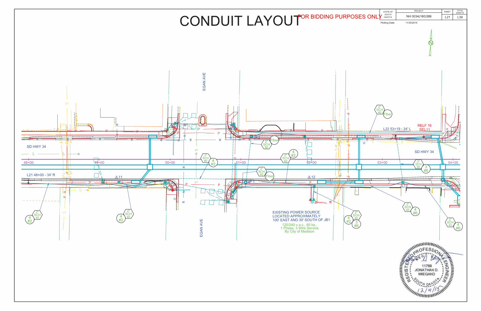
If the traffic signal systems or roadway lighting systems are constructed differently than what is stated in the plans, the Contractor shall supply as built plans to the Engineer and a copy shall be sent to the Traffic Design Engineer. The as built plans may include conduit layouts, wiring diagrams, or other drawings depicting the changes from the original plans.
SHOP DRAWING AND CATALOG CUTS SUBMITTALS
The Contractor shall submit shop drawings and catalog cuts in accordance with Section 985 of the Specifications.
Adobe PDF submittals shall be sent to the following email address: [email protected]
Upon review of the submittals, they will be sent by the Engineer to the following email address for concurrence of approvals or remarks:
EXISTING LUMINAIRE POLES AND LUMINAIRE POLE FOOTINGS
Existing roadway lighting along SD 34/2nd Street is a combination of luminaire poles on footings or direct-bury luminaire poles. At certain locations, as noted in the plans, the luminaire poles originally on footings have been removed and replaced with a direct-bury luminaire pole next to the existing footing. The footings that have not been removed are noted in the plans for removal with this project. At each roadway lighting location for salvage or removals, the plans indicate whether the roadway luminaire pole is on an existing footing or a direct-bury and whether a footing is to be removed.
SALVAGE LUMINAIRE POLE
Existing direct-bury luminaire poles SEL 1-13 shall be salvaged and delivered to the City of Madison by the Contractor. The Contractor shall notify the City 5 days before the delivery of the salvaged luminaire poles. The City contact is Chad Comes at (605) 256-7514.
All costs for work involved in the salvage and delivery of the existing luminaire poles shall be incidental to the contract unit price per each for “Salvage Luminaire Pole”.
REMOVE LUMINAIRE POLE
Existing luminaire poles on footings shall be removed by the Contractor, identified as REL 1-4 in the plans.
All costs involved with removing existing luminaire poles shall be incidental to the contract unit price per each for “Remove Luminaire Pole”.
REMOVE LUMINAIRE POLE FOOTING
Existing luminaire pole footings identified as RELF 1-20 in the plans shall be removed by the Contractor to a minimum of 2’ below the ground surface. Restoration of the disturbed area shall be to the satisfaction of the Engineer.
All costs for removing the footings of the existing luminaire poles shall be incidental to the contract unit price per each for “Remove Luminaire Pole Footing”.
REMOVE SIGNAL EQUIPMENT
All existing signal equipment removed and not relocated as part of this project, salvaged by the SDDOT, or salvaged by the City of Madison shall become the property of the Contractor.
All costs for work involved in the removal of existing signal equipment shall be incidental to the contract lump sum price for “Remove Signal Equipment”.
SALVAGE SIGNAL EQUIPMENT
Existing signal equipment noted in the plan sheets for relocation shall be salvaged and stored by the Contractor until relocated to the respective signal pole.
All costs for work involved in the salvage and storage of the existing signal equipment shall be incidental to the contract lump sum price for “Salvage Signal Equipment”.
REMOVE AND RESET LUMINAIRE POLE
Existing luminaire pole EL1 shall be removed and reset at the new location as Reset EL1 as shown on the plan sheets. A recommendation from the manufacturer will be required to be supplied to the Engineer for the design of the anchor bolts. J-hook style is no longer acceptable.
The new pole footing, junction box, and conduit under Washington Avenue have been included under their respective bid items.
It shall be the Contractor’s responsibility to obtain the bolt circle pattern and anchor bolts for the relocated poles from the pole manufacturer.
A luminaire pole and luminaire damaged during relocation shall be repaired or replaced by the Contractor at no cost to the State.
The Contractor shall intercept the 4 #4 wire on the east side of Washington Avenue, install junction box JL 15 at location of interception, and splice in new 3 #4 wire to the reset luminaire pole. The Contractor shall be responsible for field verifying connection needs to the north of JL 15.
All costs involved with removing and resetting the existing luminaire pole including new anchor bolts with associated hardware shall be incidental to the contract unit price per each for “Remove and Reset Luminaire Pole”.
Revised 12/9/2015 KAM
FOR BIDDING PURPOSES ONLY

PROJECT STATE OF SOUTH
DAKOTA NH 0034(160)386
SHEET
L3 L39
TOTAL SHEETSON-SITE INSPECTION
An on-site inspection of the traffic signals shall be conducted before acceptance of the project, once the traffic signals are completed and operational. The on-site inspection shall be conducted by the Project Engineer or Region Traffic Engineer with the Contractor, City Traffic Engineer, and the Traffic Design Engineer present.
REMOVE AND RESET SIGNAL POLE
Existing signal pole EB3 shall be removed and reset as RB3 as shown on the plan sheets. The Contract shall coordinate with the pole manufacturer to determine the necessary anchor rod dimensions to conform to Section 972C of the SDDOT Standard Specifications for Roads and Bridges. Manufacturer certification of the anchor rod design shall be provided by the Engineer.
It shall be the contractor’s responsibility to obtain the bolt circle patter and anchor bolts for the relocated poles from the pole manufacturer listed below. The poles were originally installed under PH 0034(39)386).
Signal poles, luminaire extensions, and luminaires damaged during relocation shall be repaired or replaced by the Contractor at no cost to the State.
All costs involved with removing and resetting the exiting signal poles including new anchor bolts with associated hardware, shall be incidental to the contract unit price per each for “Remove and Reset Signal Pole”.
TABLE OF FOOTING DATA
Site Designation
Footing Diameter
* FootingDepth
**Spiral Diameter
**Spiral Length
Vertical Reinforcement
L1-L25, 2’ - 0” 10’ - 0” 1’ - 8” 65’ - 3” 8-#7 x 9’ - 6” Reset EL1 2’ - 0” 7’ - 0” 1’ - 8” 49’ - 6” 8-#7 x 6’ - 6” RB3 & A3 3’ - 0” 12’ - 0” 2’ - 8” 120’ - 9” 14-#8 x 11’ -6”
* Footing depth shall be below ground level.** The size of all spirals shall be #3.
SUBSURFACE CONDITIONS
The subsurface soil along SD 34/2nd Street through Madison between stations 10+00 to 39+00+/- consist of a brown silt-clay with pebbles from 0’ - 23.5’. From stations 39+00+/- to 57+00+/- the subsurface condition consists of a brown clay-silt from 0’ - 3’ followed by a brown gravel-sand from 3’ - 12’ then a heavy gravel from 12’ – 18.5’ all overlaying a blue-gray silt-clay. From stations 57+00+/- to 64+00 the subsurface condition consists of a gravel-sand from 0’ - 15’ overlaying a gray-brown gravel-clay from 15’ - 23’. Groundwater was not measured during the borings. Caving was noted between stations 39+00 and 64+00 from 6’ - 9.9’ below the surface.
On the south side of the intersection of SD 34/2nd Street & SD 34/Washington Ave. the subsurface condition consists of a brown gravel from 0’ – 7’ followed by a brown clay-gravel from 7’ – 9’ over a brown fine sand from 9’ – 16’ all overlaying a gray clay from 16’ – 30’. Cobbles were encountered from 21’ – 24’. Water was encountered in the boring on the southeast corner at 16.3’. Caving was noted due to the gravel and general granular consistency of the material at 6’ below the surface.
No borings were completed at the intersection of SD 34/2nd Street and Egan Ave. The Soils subsurface investigation from 2014 was completed within the vicinity of the intersection near the southwest corner. The subsurface condition at the intersection consists of brown silt-clay from 0’ – 3’ followed by light red gravel-sand from 3’ – 15’. Groundwater was not encountered and caving occurred initially at 11.9’ below the surface.
Due to the subsurface conditions, concrete placement operations should closely follow excavation procedures during construction. The longer the excavations are left open the more likely caving may occur. If caving soils are encountered during excavation, casing may be required to construct the cylindrical footings.
Concrete shall not be dropped through standing water. If water is present in the excavation it shall be removed prior to concrete placement or the concrete shall be tremied. If caving occurs during dewatering the concrete shall be placed through a tremie or by means of a casing.
Casing will be required due to caving soils for the traffic signal footing at the corner of SD 34/2nd Street and SD 34/Washington Ave. Casing shall be of sufficient strength to withstand handling and installation procedures. The casing material may consist of sonotube, corrugated metal pipe, pvc, smooth metal pipe or any other material as approved by the Engineer.
The boring logs and laboratory tests are available for review at the Central Office in Pierre. If questions arise or additional information is needed concerning the cylindrical footings contact the Geotechnical Engineering Activity in Pierre at 605.773.3401.
POLES
Cantilever traffic signal supports, including anchor bolts, shall be designed for fatigue in accordance with Fatigue Importance Category III without galloping and truck induced gusts.
Signal poles shall have rotatable mast arms.
Signal pole luminaire extensions (A3) shall have a 50 Ft. mounting height with 8 Ft. arm.
Luminaire pole extensions for L1, L2, L4, L6-L18 shall have a 50 Ft. mounting height with 8 Ft. arm. Luminaire pole extensions for L3, L5, L19-25 shall have a 50 Ft. mounting height with 4 Ft. arm.
Luminaire poles L1-25 shall be designed to include loadings created by banners that are 2.5 Ft. wide and 7 Ft. long, mounted 15 Ft. from the bottom of the pole to the bottom of the banner.
All poles shall have a convenience duplex festoon outlet receptacle (15 amp, 3 wire) suitable for outdoor use.
LUMINAIRES
The accepted design for the roadway luminaires L1 through L25 shall provide 1.2 and greater average maintained foot-candles and a uniformity ratio (average maintained to minimum maintained foot-candles) of 3:1 and less using the following parameters:
Setback: 0 Ft.Lamp Loss Factor (LLF): 0.7 Width of Lighted Area: 60 Ft. (Edge of travel lane to edge
of travel lane) Spacing: 418 ft. one side, 209 ft. staggered
Configuration: Two-sided, staggeredMounting Height: 50 Ft.Lamp: LED
The following LED roadway luminaire meets the requirements for this design:
a.) Cooper Lighting: Test No. NVN-AE-06-E-U-T2R.ies, P127669 Model # NVN-AE-06-E-U-T2R Roadway Type II, Short, Semi-Cutoff Distribution Luminaire Watts: 315W Luminaire Input Voltage: 120 VAC Luminaire Absolute Lumens: 32,542 lm, 4000K, 70 CRI Luminaire Efficacy: 103 lm/W Provide each luminaire with NEMA twist lock photo eye socket and photo eye Finish: Gray polyester powder coat
Three copies of the isofootcandle charts and utilization curves shall be furnished to the Engineer for approval. The Contractor must get approval from the Engineer prior to installation of the luminaires.
LUMINAIRES ON SIGNAL POLES
The existing roadway luminaires on signal poles shall be removed and replaced with LED roadway luminaires (EB1, EB2, RB3, EB4, EA1, EA2, A3, EA4) that meet design requirements for roadway luminaires L1 through L25.
All costs for removing Roadway Luminaire, 400W with P.E. from signal pole extensions shall be incidental to the contract lump sum price for “Remove Signal Equipment”.
All costs for installing Roadway Luminaire, LED with Photoelectric Cell (EB1, EB2, RB3, EB4, EA1, EA2, A3, EA4 on existing and new signal pole luminaire extensions as provided in the plans, materials, and labor shall be incidental to “Roadway Luminaire, LED with Photoelectric Cell”.
FOR BIDDING PURPOSES ONLY

PROJECT STATE OF SOUTH
DAKOTA NH 0034(160)386
SHEET
L4 L39
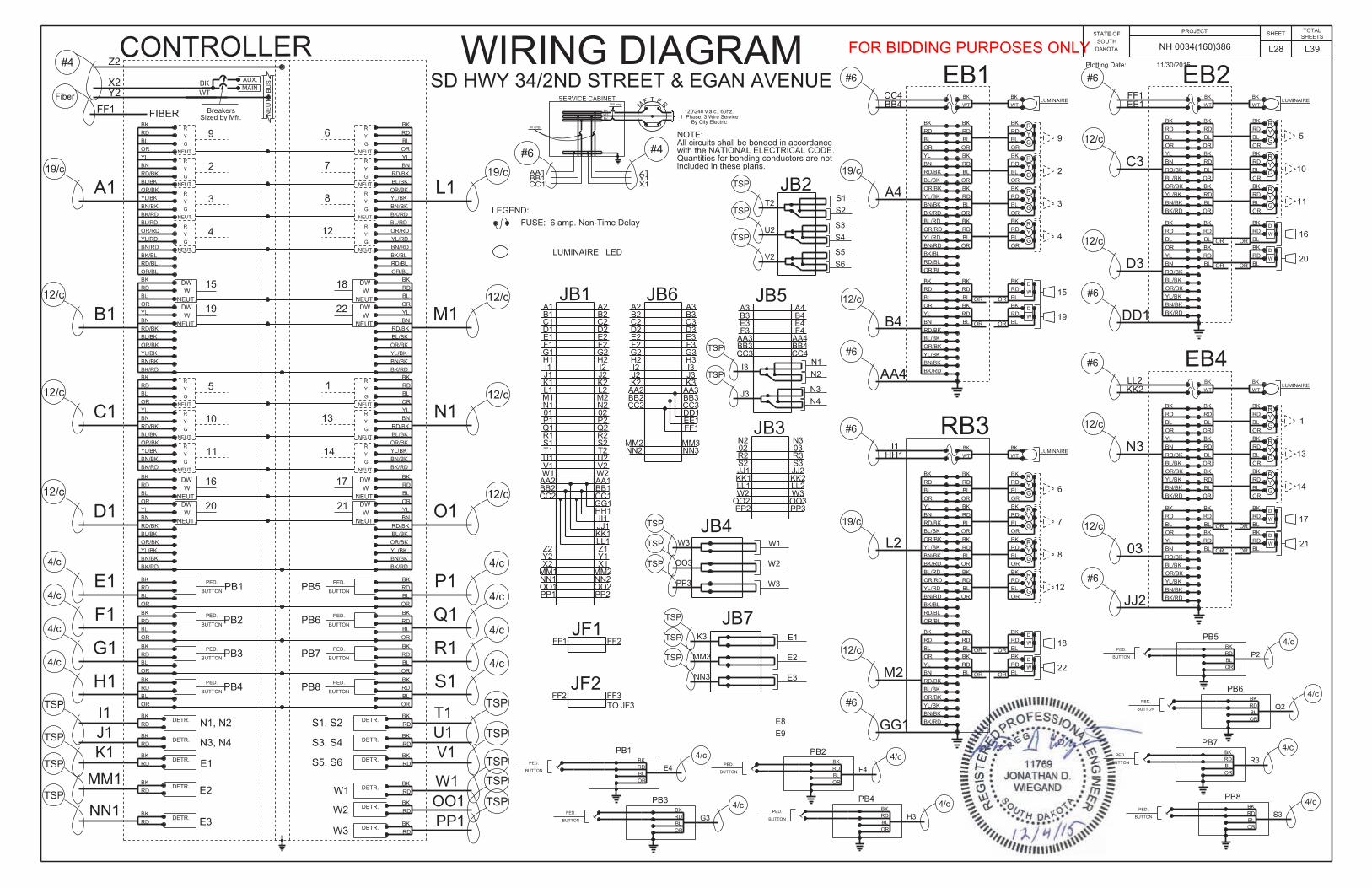
TOTAL SHEETSTRAFFIC SIGNAL CONTROLLER
The existing traffic signal controller and cabinet at the following intersections shall be salvaged and relocated within the respective intersection as shown on the plans.
1. SD 34/2nd Street and Egan Avenue intersection and2. SD 34/2nd Street and Washington Avenue intersection
The controller cabinet shall be pad mounted.
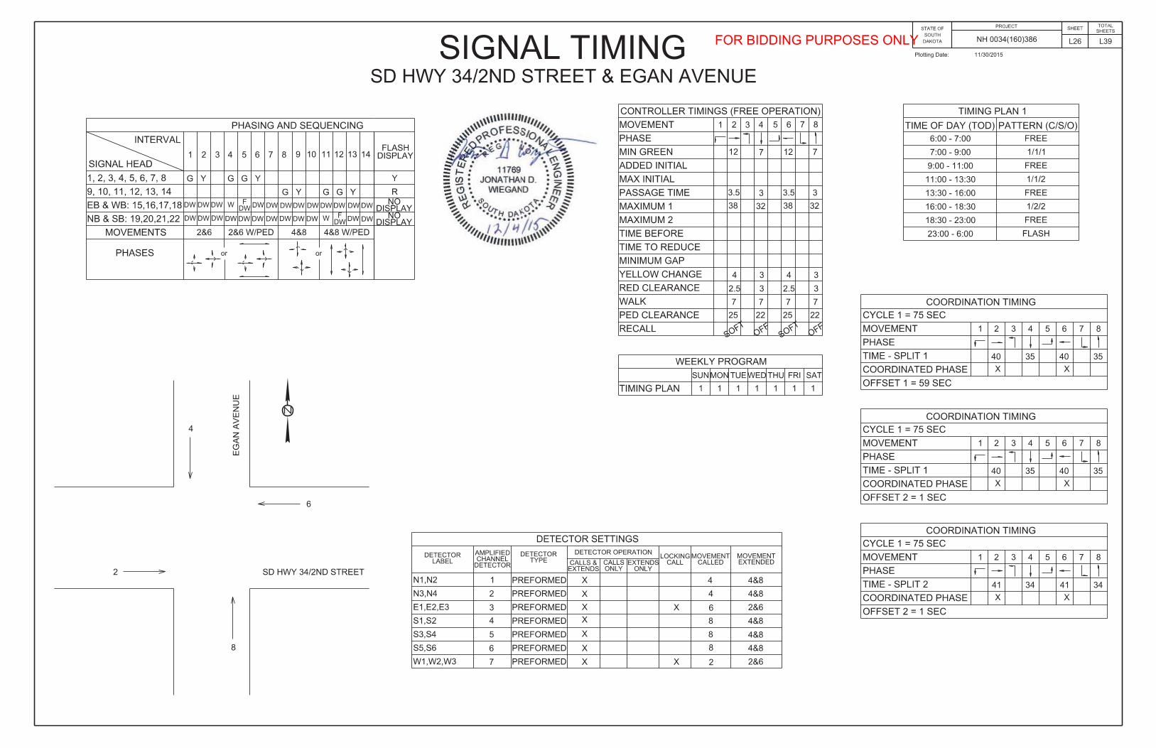
The Contractor shall be responsible for programming controllers with the existing signal timings currently used in the controllers. If needed to reprogram the controllers, the Contractor shall be responsible for obtaining the existing signal timing prior to relocation of the controller and cabinet.
All costs for salvaging and relocating the existing traffic signal controller and cabinet at the SD 34/2nd Street and Egan Avenue intersection and SD 34/2nd Street and Washington Avenue intersection shall be incidental to the contract lump sum price for “Relocate Signal Equipment”.
All costs for constructing the concrete pad and footing, materials, labor, and installing the relocated controller cabinet shall be incidental to the contract lump sum price for “Relocate Signal Equipment”.
MASTER CONTROLLER
The master controller shall be capable of operating by the time of day or traffic responsive. The master controller shall be compatible with any new or existing equipment used by the City of Madison. Existing controllers at the SD 34/2nd Street intersections with Egan Avenue and Washington Avenue are the following:
Egan Avenue: Econolite ASC-2 Washington Avenue: Econolite ASC-3
The master controller for the coordinated signal system shall be located at the intersection of SD 34/2nd Street and Washington Avenue.
CONTROLLER SOFTWARE
Two copies of controller software shall be provided. One copy of the software shall be supplied to the City of Madison City Engineer and the second copy of the software shall be supplied to the South Dakota Department of Transportation Traffic Design Engineer in the Office of Road Design.
The controller software shall provide communication between a personal computer and the controllers being supplied by the contractor. The controller software shall allow permanent storage of all controller input data on a hard disk drive. The controller software shall work with isolated intersections as well as a closed loop system.
All costs for the controller software shall be incidental to the contract unit price per each for “Master Controller”.
CONTROLLER PROGRAMMING
Existing controllers shall be reprogrammed to use the patterns and timings specified on the Signal Timing Sheets by a qualified technician. Costs for reprogramming the controllers shall be incidental to the contract lump sum price for “Relocate Signal Equipment”.
The Contractor shall furnish the Road Design Office with a copy of the data programmed into the Controllers prior to the full operation of the Controller for approval. The address is as follows:
John Less Traffic Design Engineer Office of Road Design 700 East Broadway Pierre, SD 57501
SIGNAL BACKPLATES
Signal backplates shall extend not less than 5 inches from the edge of the signal head at the top, bottom, and sides. The bottom of the backplate on vehicle signal faces mounted directly above pedestrian signal indications shall be sized to permit the separate adjustment of the vehicle and pedestrian signal indication and may be less than 4 inches.
FIBER OPTIC CABLE MODEM
The Contractor shall furnish and install fiber optic modems in the relocated controllers at the SD 34/2nd Street intersections with Egan Avenue and Washington Avenue.
All costs for furnishing and installing fiber optic modems in relocated controllers shall be incidental to the contract lump sum price for “Relocate Signal Equipment”.
SD34/2nd STREET AND EGAN AVENUE INTERSECTION PEDESTRIAN PUSH BUTTONS
The work at the Egan Avenue intersection includes the removal of pedestrian push buttons from existing signal poles.
New pedestrian push buttons shall be installed on new pedestrian push button poles as shown on the Signal Layout sheet.
All cost for labor and materials to fill or cover holes, to the satisfaction of the Engineer, in existing signal poles from the removed pedestrian push buttons shall be incidental to the contract lump sum price for “Relocate Signal Equipment”.
SECONDARY SERVICE DISCONNECT
The Contractor shall install an additional NEMA 3R rainproof, 60 amp rated, non-fused safety switch (with lock) adjacent to the relocated traffic signal controller cabinets at the SD 34/2nd Street intersections with Egan Avenue and Washington Avenue. The disconnect shall be mounted on a galvanized steel post in accordance with Standard Plate 635.41.
All costs for work involved furnishing and installing the Secondary Service Disconnect shall be incidental to the contract unit price per each for “Electrical Service Cabinet”.
CONDUIT AT 42+00-43’ Lt. TO 42+55-43’ Lt.
The Contractor shall intercept existing conduit at approximately Sta. 42+00-43’ Lt., install junction box JL16 at Sta. 42+00-43’ Lt., and install electrical conduit from Sta. 42+00-43’ Lt. to Sta. 42+55-43’ +/- Lt. as shown in the plans. The owner will be moving the sign to the east side of the property. Landowner is responsible for the electrical connections. The Contractor shall coordinate any driveway closures or access restrictions as part of the conduit installation with the property owner.
TRAFFIC SIGNAL METER SOCKETS
The meter sockets provided for traffic signals by the Contractor shall be a 200 amp, positive by-pass.
FOR BIDDING PURPOSES ONLY

PROJECT STATE OF SOUTH
DAKOTA NH 0034(160)386
SHEET
L5 L39
TOTAL SHEETSFIBER OPTIC CABLE
The fiber optic cable shall be a 24 strand fiber optic cable with 24 singlemode with each buffer containing six fibers. The buffer tubes shall be color coded according to EIA/TIA specifications.
Fiber optic cable provided on this project shall meet the latest applicable REA PE-90 Specifications for single mode. All fiber optic cable shall be rated for outdoor use.
Singlemode optical cable shall have the following optical and physical characteristics:
1. Cladding diameter of 125μm +/- 2μm.2. Zero dispersion slope shall be 0.092 ps/ (nm2 km) or less.3. Zero dispersion wavelength, 1300 to 1322 nm.4. Cutoff wavelength, less than 1250 nm.5. Maximum attenuation at 1310 nm shall be 0.4 dB per Kilometer.6. The outside diameter shall be less than 22.1 nm.7. One factory fusion splice per kilometer per fiber shall be allowed.
The fiber optic cable shall have a seven-core configuration, dielectric central strength member, and thermoplastic tubes. The minimum bending radii of the cable shall be 209.5 mm under a static load and 419.1 mm during installation. The installation tensile load rating shall be 2.7 kPa.
The cable core interstices shall be filled with water blocking material. If a gel compound is used, the gel compound shall be readily removable with a nontoxic solvent.
Fiber optic cable shall be terminated in the controller cabinet with a wall mounted distribution enclosure. The distribution enclosure shall be dust and moisture resistant. The size of the distribution enclosure shall be adequate for the number of fibers to be used. The distribution enclosure shall be mounted in the controller cabinet where it does not interfere with normal cabinet maintenance. The fiber optic cable shall be prepared in accordance with the manufacturer’s recommendations and have sufficient length to reach the interface panel. Only fibers needed to operate the equipment plus two spare shall be terminated with LC connectors. The connector loss after 1000 matings shall be less than 0.2 dB. The connector return loss shall not be greater than 45 dB for singlemode. All other fibers shall be capped and sealed in accordance with the manufacturer’s recommendations.
The fiber optic cable shall be installed in accordance with the manufacturer’s recommendations and the NEC. Slack cable shall be left in each controller and junction box. All junction boxes except for the junction at the controller shall have 6.5’ of slack. The junction box at the controller cabinet shall have 19.5’ of slack. Controller cabinets shall have 2’ of slack. Slack cable shall be coiled and tied in a minimum of three places around the coil. No splices shall be allowed in the fiber optic cable except in the controllers. Splices shall be of the epoxy/polish type.
The contractor shall test the fiber optic cable after the installation to verify the integrity of the fiber.
The supplier of the fiber optic cable shall supervise the installation and testing of the fiber optic cable. The supplier of the fiber optic cable shall provide training to personnel of the City in the installation and maintenance of the fiber optic cable.
The payment for supplying, installing, testing, and training of city personnel shall be incidental to the contract unit price per foot for “24 Strand Fiber Optic Cable”.
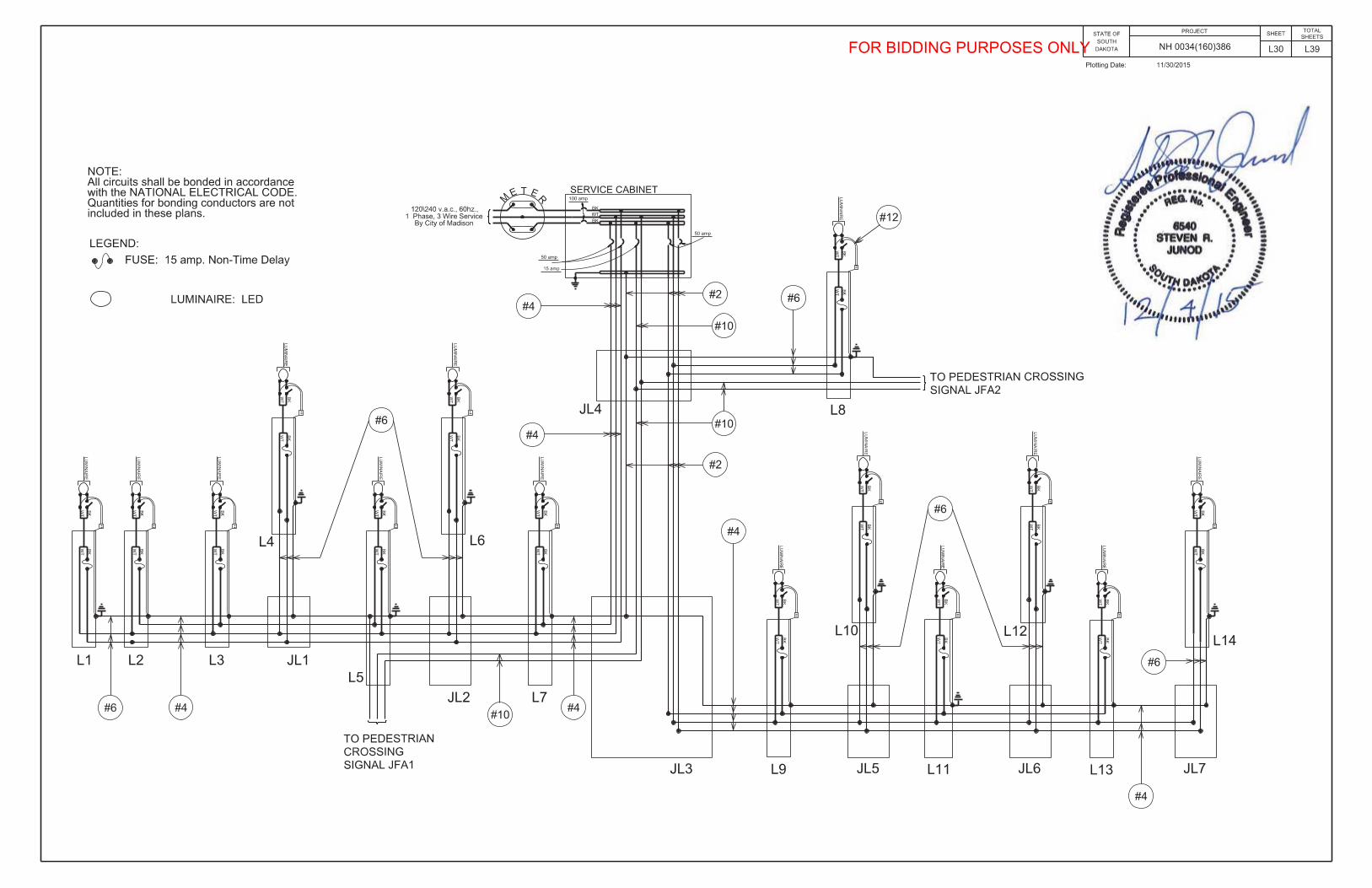
ROADWAY LIGHTING AT US 81/SD 34 INTERSECTION ORDER OF WORK
The existing roadway lighting conduit and wires to be left-in-place at the US 81/SD 34 intersection has been noted in the plans. This information was obtained from project HES 0081-94 and F0081(99)94 and the project survey. The Contractor shall be responsible for field verifying existing roadway lighting conduit and wires to complete the work of the new connection.
Roadway luminaires EL2 and EL3 shall be connected to the existing power feed with the following order of work: The Contractor shall:
1. Locate and intercept existing power feeder. Cut and abandon southportion of feeder. Place new junction box over feeder (JL17) and re-route conduit and conductors into junction box. Splice feederconductors to new conductors.
2. Route new conduit run into Existing Junction Box JB17. This mayrequire boring under sections of existing pavement that will be left-ion-place. Disconnect existing feeder conductors and splice newfeeder conductors to existing load conductors. Cut back andabandon existing feeder conduit/conductors in place. ExistingJunction Box JB17 shall be reset with the construction of the curbramps in the southwest quadrant.
All costs for modifications to the existing wires and conduit, including disconnecting and connecting existing conductors within JL17 and JB17, in order to make the roadway luminaires EL2 and EL3 fully operational shall be incidental to the contract unit price per foot for each respective conduit and wire items.
Revised 12/9/2015 KAM
FOR BIDDING PURPOSES ONLY

L6 L39Plotting Date: 11/30/15
2" 4" 2" 3" 1/C 1/C 4/C 7/C 12/C 19/C 24/C #16 2/C#4 #6 AWG #10
AWG AWG AWGFt Ft Ft Ft Ft Ft Ft Ft Ft Ft Ft Ft Ft Ft
JB1 Service Cabinet 170 525 525JB1 Controller 30 105 280 210 70 385JB1 Signal Pole RB3 20 75 25 25JB1 Ped PB Pole PB5 20 25JB1 Ped PB Pole PB6 10 15JB1 JB2 20 75JB1 JB3 100 315 210 210 315JB3 Ped PB Pole PB7 20 25JB3 Ped PB Pole PB8 10 15JB3 Signal Pole EB4 30 105 70JB3 JB4 95 300JB1 JB6 105 325 435 325 110 545JB6 JB7 120 375JB6 Ped PB Pole PB3 15 20JB6 Ped PB Pole PB4 20 25JB6 Signal Pole EB2 20 75 50JB6 JB5 95 295 200 100 100 200JB5 Ped PB Pole PB1 25 30JB5 Ped PB Pole PB2 15 20JB5 Signal Pole EB1 20 50 25 25
Signal Pole EB1Signal Pole EB2Signal Pole RB3 175 65Signal Pole EB4Ped PB Pole PB1 10Ped PB Pole PB2 10Ped PB Pole PB3 10Ped PB Pole PB4 10Ped PB Pole PB5 10Ped PB Pole PB6 10Ped PB Pole PB7 10Ped PB Pole PB8 10
FiberEgan Ave Contr JF1 40 50
JF1 JF2 70 80JF2 JF3 430 70 515JF3 JF4 455 80 555JF4 Wash Ave Contr 40 50
1595 0 30 220 300 630 1765 1555 0 1015 330 0 2195 65 1250
Rigid Conduit IMSA Copper Cable, K2Copper Wire
Subtotal:
Schedule 40
Location to Location
#14 AWG
SD 34 and Egan Ave
Schedule 80Fiber Optic
CableTwisted
Shielded PairPole and
Bracket Cable
TOTALSHEETS
NH 0034(160)386
STATE OF SOUTH
DAKOTA
PROJECTSHEETTABLE OF CONDUIT AND CABLE QUANTITIES
FOR BIDDING PURPOSES ONLY

L7 L39Plotting Date: 11/30/15
2" 4" 2" 3" 1/C 1/C 4/C 7/C 12/C 19/C 24/C #16 2/C#4 #6 AWG #10
AWG AWG AWGFt Ft Ft Ft Ft Ft Ft Ft Ft Ft Ft Ft Ft Ft
Rigid Conduit IMSA Copper Cable, K2Copper Wire
Schedule 40
Location to Location
#14 AWGSchedule 80Fiber Optic
CableTwisted
Shielded PairPole and
Bracket Cable
TOTALSHEETS
NH 0034(160)386
STATE OF SOUTH
DAKOTA
PROJECTSHEETTABLE OF CONDUIT AND CABLE QUANTITIES
JA3 Service Cabinet 155 480 480JA1 Controller 25 90 240 90 120 330JA1 Signal Pole EA1 20 75 25 25JA1 JA2 15 40JA1 Ped PB Pole PA1 20 25JA1 Ped PB Pole PA2 15 20JA1 JA3 95 300 300 400 200 200 500JA3 Ped PB Pole PA3 30 35JA3 Ped PB Pole PA4 20 25JA3 Signal Pole EA2 25 90 30 30JA3 JA4 110 230JA3 JA5 95 300 200 100 100 300JA5 Ped PB Pole PA5 20 25JA5 Ped PB Pole PA6 15 20JA5 Signal Pole A3 25 90 30 30JA5 JA6 25 90JA1 JA7 110 345 230 115 345JA7 Ped PB Pole PA7 15 20JA7 Ped PB Pole PA8 20 25JA7 Signal Pole EA4 15 60 20JA7 JA8 120 375
Signal Pole EA1Signal Pole EA2Signal Pole A3 175 65Signal Pole EA4Ped PB Pole PA1 10Ped PB Pole PA2 10Ped PB Pole PA3 10Ped PB Pole PA4 10Ped PB Pole PA5 10Ped PB Pole PA6 10Ped PB Pole PA7 10Ped PB Pole PA8 10
665 25 0 300 870 1740 1520 475 0 0 640 2210 65 0
Traffic Signals Total: 2260 55 220 600 1500 3505 3075 475 1015 330 640 4405 130 1250
Subtotal:
SD 34 and Washington Ave
FOR BIDDING PURPOSES ONLY

L8 L39Plotting Date: 11/30/15
2" 2" 3" 1/C 1/C 1/C 1/C 1/C 2/C 2/C#2 #4 #6 #10 #14 #12 #10
AWG AWG AWG AWG AWG AWG AWGFt Ft Ft Ft Ft Ft Ft Ft Ft Ft
L1 L2 120 375L2 L3 160 660L3 JL1 235 970JL1 L4 80 250JL1 L5 195 805L5 JFA1 50L5 JL2 215 890 445JL2 L6 80 250JL2 L7 120 80 825 415L7 JL3 90 375 190JL3 JL4 80 330 250 170JL4 Service Cabinet 150 620 465 310JL4 L8 100 310 210L8 JFA2 50JL3 L9 240 80 1320L9 JL5 210 870JL5 L10 80 250JL5 L11 120 80 825L11 JL6 215 890JL6 L12 80 250JL6 L13 120 80 825L13 JL7 215 665JL7 L14 80 250
L15 JL8 200 620JL8 L16 80 250JL8 L17 110 80 785L17 JL9 200 825JL9 L18 85 265JL9 L19 135 80 890L19 JL10 215 890JL10 L20 80 250JL10 L21 120 110 950L21 JL11 140 580JL11 JL12 140 145 1175JL12 Service Cabinet 50 210 160JL12 JL13 135 560JL13 L22 75 235JL13 L23 100 95 805L23 JL14 215 890JL14 L24 80 250JL14 L25 140 80 680
4135 1830 230 5645 12245 6900 1840 0 0 0
TOTALSHEETS
NH 0034(160)386
STATE OF SOUTH
DAKOTA
PROJECTSHEETTABLE OF CONDUIT AND CABLE QUANTITIES
Pole and Bracket Cable
Copper Wire
Schedule 40 Schedule 80
Location to LocationLighting - Highland to Union
Rigid Conduit
Subtotal:
Lighting - Union to Lee
FOR BIDDING PURPOSES ONLY

L9 L39Plotting Date: 11/30/15
2" 2" 3" 1/C 1/C 1/C 1/C 1/C 2/C 2/C#2 #4 #6 #10 #14 #12 #10
AWG AWG AWG AWG AWG AWG AWGFt Ft Ft Ft Ft Ft Ft Ft Ft Ft
TOTALSHEETS
NH 0034(160)386
STATE OF SOUTH
DAKOTA
PROJECTSHEETTABLE OF CONDUIT AND CABLE QUANTITIES
Pole and Bracket Cable
Copper Wire
Schedule 40 Schedule 80
Location to Location
Rigid Conduit
42+00-43' Lt. 42+55-43' Lt. 55JL15 Reset EL1 70 220JL17 Existing JB17 125 540
Luminaire Pole L1 45 65Luminaire Pole L2 45 65Luminaire Pole L3 45 65Luminaire Pole L4 45 65Luminaire Pole L5 45 65Luminaire Pole L6 45 65Luminaire Pole L7 45 65Luminaire Pole L8 45 65Luminaire Pole L9 45 65Luminaire Pole L10 45 65Luminaire Pole L11 45 65Luminaire Pole L12 45 65Luminaire Pole L13 45 65Luminaire Pole L14 45 65Luminaire Pole L15 45 65Luminaire Pole L16 45 65Luminaire Pole L17 45 65Luminaire Pole L18 45 65Luminaire Pole L19 45 65Luminaire Pole L20 45 65Luminaire Pole L21 45 65Luminaire Pole L22 45 65Luminaire Pole L23 45 65Luminaire Pole L24 45 65Luminaire Pole L25 45 65Luminaire Pole Reset EL1 90 65
0 250 0 0 760 0 0 90 1125 1690
Lighting Total: 4135 2080 230 5645 13005 6900 1840 90 1125 1690
Luminaire Pole
Subtotal:
Misc.
FOR BIDDING PURPOSES ONLY

FOR BIDDING PURPOSES ONLY

FOR BIDDING PURPOSES ONLY

FOR BIDDING PURPOSES ONLY

FOR BIDDING PURPOSES ONLY

FOR BIDDING PURPOSES ONLY

FOR BIDDING PURPOSES ONLY

FOR BIDDING PURPOSES ONLY

FOR BIDDING PURPOSES ONLY

FOR BIDDING PURPOSES ONLY

FOR BIDDING PURPOSES ONLY

FOR BIDDING PURPOSES ONLY
FOR BIDDING PURPOSES ONLY

FOR BIDDING PURPOSES ONLY

FOR BIDDING PURPOSES ONLY

FOR BIDDING PURPOSES ONLY

FOR BIDDING PURPOSES ONLY
FOR BIDDING PURPOSES ONLY

FOR BIDDING PURPOSES ONLY
FOR BIDDING PURPOSES ONLY

FOR BIDDING PURPOSES ONLY
FOR BIDDING PURPOSES ONLY

FOR BIDDING PURPOSES ONLY

FOR BIDDING PURPOSES ONLY

FOR BIDDING PURPOSES ONLY

FOR BIDDING PURPOSES ONLY

FOR BIDDING PURPOSES ONLY

FOR BIDDING PURPOSES ONLY

FOR BIDDING PURPOSES ONLY

FOR BIDDING PURPOSES ONLY

FOR BIDDING PURPOSES ONLY