timing belt (5s–fe) - celicatech - powered by...
TRANSCRIPT

REMOVAL OF TIMING BELT1. DISCONNECT CABLE FROM NEGATIVE TERMINAL
OF BATTERYCAUTION: Work must be started after approx. 20seconds or longer from the time the ignition switch isturned to the ”LOCK” position and the negative (–) ter-minal cable is disconnected from the battery.
2. REMOVE RH FRONT WHEEL3. REMOVE RH ENGINE UNDER COVER4. (w/ CRUISE CONTROL SYSTEM (w/o ABS))
REMOVE CRUISE CONTROL ACTUATOR(See page 11 on page EM–270)
5. REMOVE ALTERNATOR (See page CH–9)
TIMING BELT (5S–FE)COMPONENTS
–ENGINE MECHANICAL Timing Belt (5S–FE)EM–67
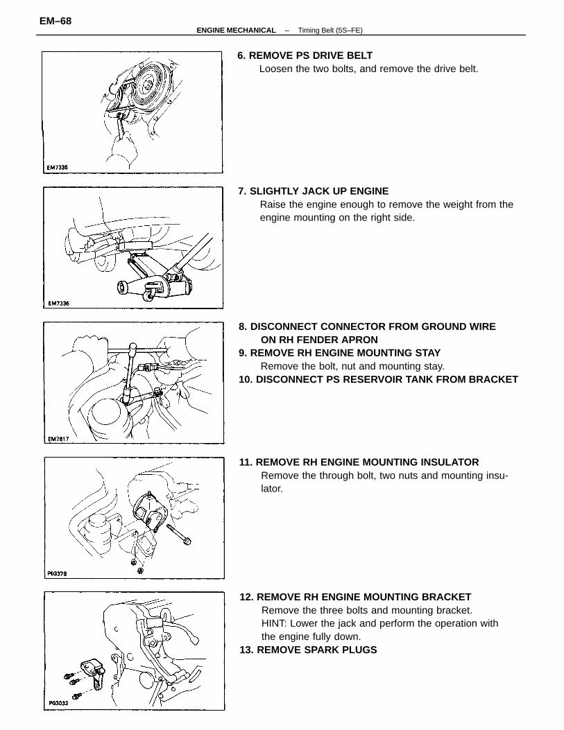
8. DISCONNECT CONNECTOR FROM GROUND WIREON RH FENDER APRON
9. REMOVE RH ENGINE MOUNTING STAYRemove the bolt, nut and mounting stay.
10. DISCONNECT PS RESERVOIR TANK FROM BRACKET
12. REMOVE RH ENGINE MOUNTING BRACKETRemove the three bolts and mounting bracket.HINT: Lower the jack and perform the operation withthe engine fully down.
13. REMOVE SPARK PLUGS
7. SLIGHTLY JACK UP ENGINERaise the engine enough to remove the weight from theengine mounting on the right side.
11. REMOVE RH ENGINE MOUNTING INSULATORRemove the through bolt, two nuts and mounting insu-lator.
6. REMOVE PS DRIVE BELTLoosen the two bolts, and remove the drive belt.
–ENGINE MECHANICAL Timing Belt (5S–FE)EM–68
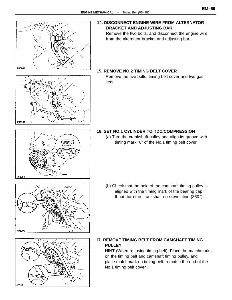
17. REMOVE TIMING BELT FROM CAMSHAFT TIMINGPULLEYHINT (When re–using timing belt): Place the matchmarkson the timing belt and camshaft timing pulley, andplace matchmark on timing belt to match the end of theNo.1 timing belt cover.
14. DISCONNECT ENGINE WIRE FROM ALTERNATORBRACKET AND ADJUSTING BARRemove the two bolts, and disconnect the engine wirefrom the alternator bracket and adjusting bar.
15. REMOVE NO.2 TIMING BELT COVERRemove the five bolts, timing belt cover and two gas-kets.
16. SET NO.1 CYLINDER TO TDC/COMPRESSION(a) Turn the crankshaft pulley and align its groove with
timing mark ”0” of the No.1 timing belt cover.
(b) Check that the hole of the camshaft timing pulley isaligned with the timing mark of the bearing cap.If not, turn the crankshaft one revolution (360°).
–ENGINE MECHANICAL Timing Belt (5S–FE)EM–69
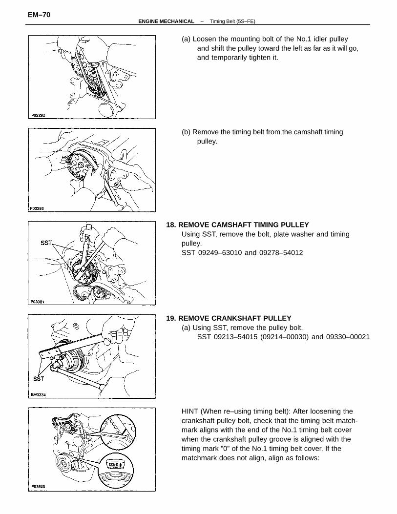
HINT (When re–using timing belt): After loosening thecrankshaft pulley bolt, check that the timing belt match-mark aligns with the end of the No.1 timing belt coverwhen the crankshaft pulley groove is aligned with thetiming mark ”0” of the No.1 timing belt cover. If thematchmark does not align, align as follows:
18. REMOVE CAMSHAFT TIMING PULLEYUsing SST, remove the bolt, plate washer and timingpulley.SST 09249–63010 and 09278–54012
19. REMOVE CRANKSHAFT PULLEY(a) Using SST, remove the pulley bolt.
SST 09213–54015 (09214–00030) and 09330–00021
(a) Loosen the mounting bolt of the No.1 idler pulleyand shift the pulley toward the left as far as it will go,and temporarily tighten it.
(b) Remove the timing belt from the camshaft timingpulley.
–ENGINE MECHANICAL Timing Belt (5S–FE)EM–70
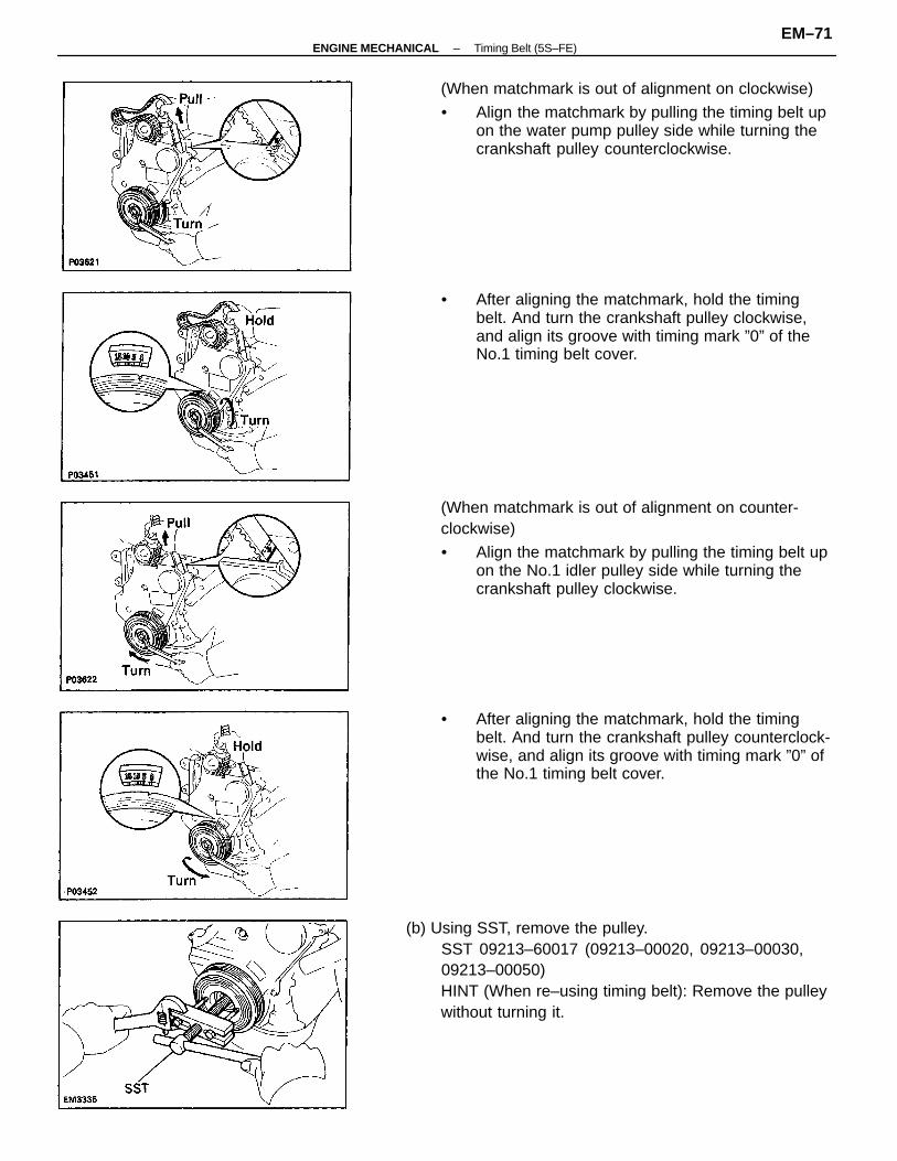
(b) Using SST, remove the pulley.SST 09213–60017 (09213–00020, 09213–00030,09213–00050)HINT (When re–using timing belt): Remove the pulleywithout turning it.
(When matchmark is out of alignment on counter-clockwise)
• Align the matchmark by pulling the timing belt upon the No.1 idler pulley side while turning thecrankshaft pulley clockwise.
(When matchmark is out of alignment on clockwise)
• Align the matchmark by pulling the timing belt upon the water pump pulley side while turning thecrankshaft pulley counterclockwise.
• After aligning the matchmark, hold the timingbelt. And turn the crankshaft pulley clockwise,and align its groove with timing mark ”0” of theNo.1 timing belt cover.
• After aligning the matchmark, hold the timingbelt. And turn the crankshaft pulley counterclock-wise, and align its groove with timing mark ”0” ofthe No.1 timing belt cover.
–ENGINE MECHANICAL Timing Belt (5S–FE)EM–71
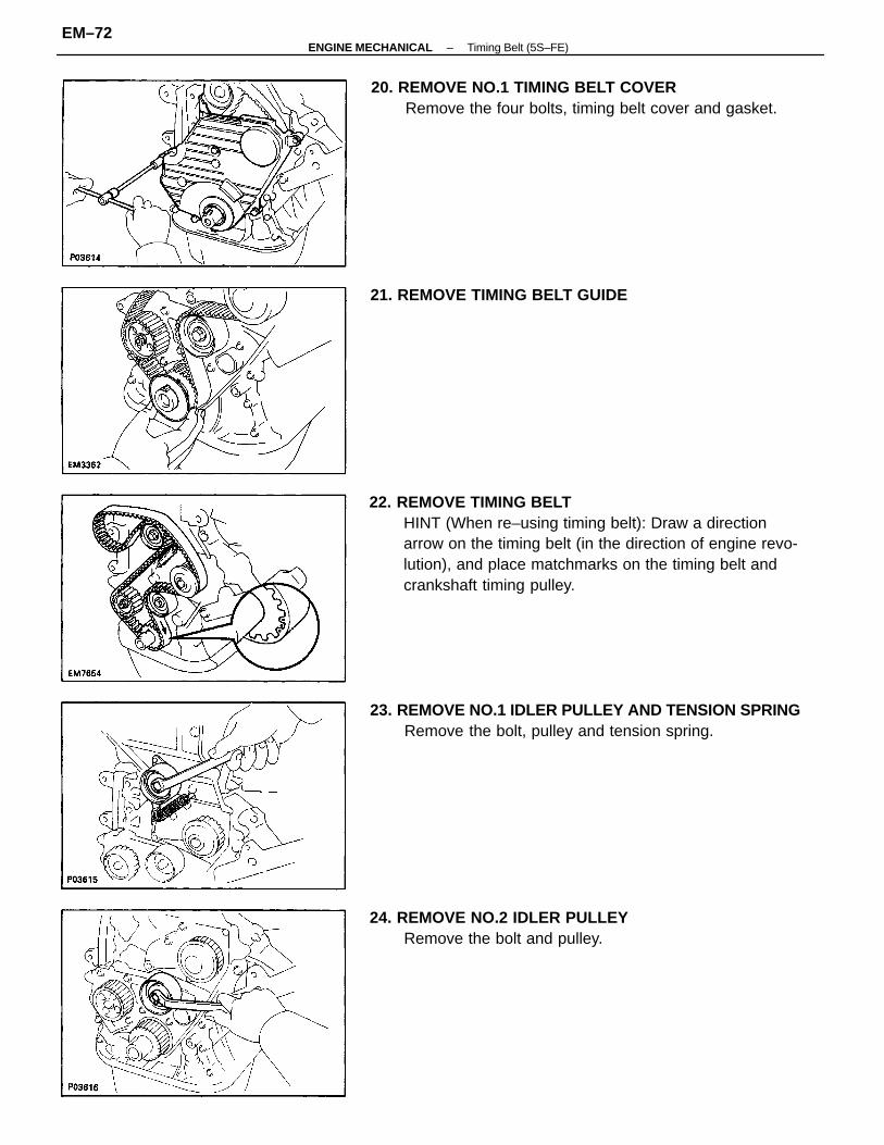
22. REMOVE TIMING BELTHINT (When re–using timing belt): Draw a directionarrow on the timing belt (in the direction of engine revo-lution), and place matchmarks on the timing belt andcrankshaft timing pulley.
23. REMOVE NO.1 IDLER PULLEY AND TENSION SPRINGRemove the bolt, pulley and tension spring.
20. REMOVE NO.1 TIMING BELT COVERRemove the four bolts, timing belt cover and gasket.
24. REMOVE NO.2 IDLER PULLEYRemove the bolt and pulley.
21. REMOVE TIMING BELT GUIDE
–ENGINE MECHANICAL Timing Belt (5S–FE)EM–72
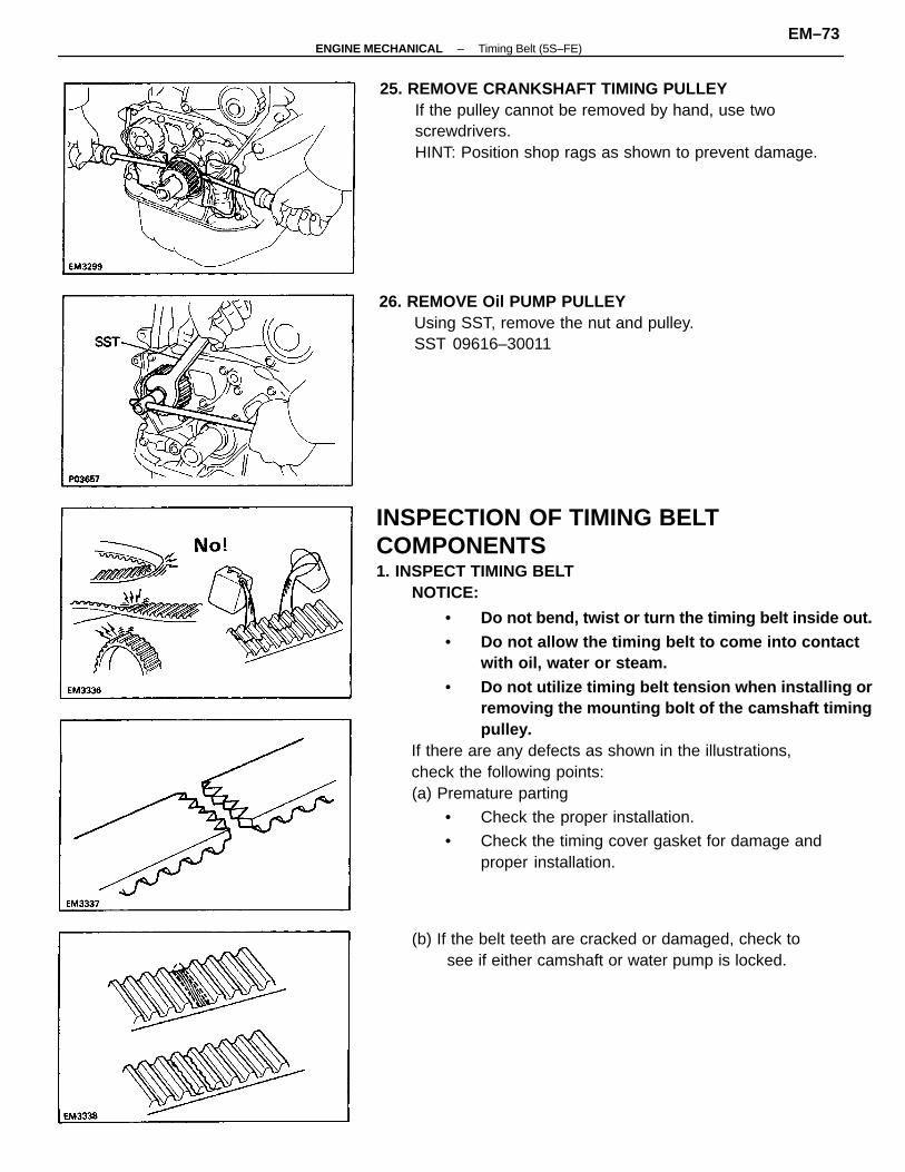
INSPECTION OF TIMING BELTCOMPONENTS1. INSPECT TIMING BELT
NOTICE:
• Do not bend, twist or turn the timing belt inside out.• Do not allow the timing belt to come into contact
with oil, water or steam.• Do not utilize timing belt tension when installing or
removing the mounting bolt of the camshaft timingpulley.
If there are any defects as shown in the illustrations,check the following points:(a) Premature parting
• Check the proper installation.
• Check the timing cover gasket for damage andproper installation.
25. REMOVE CRANKSHAFT TIMING PULLEYIf the pulley cannot be removed by hand, use twoscrewdrivers.HINT: Position shop rags as shown to prevent damage.
26. REMOVE Oil PUMP PULLEYUsing SST, remove the nut and pulley.SST 09616–30011
(b) If the belt teeth are cracked or damaged, check tosee if either camshaft or water pump is locked.
–ENGINE MECHANICAL Timing Belt (5S–FE)EM–73
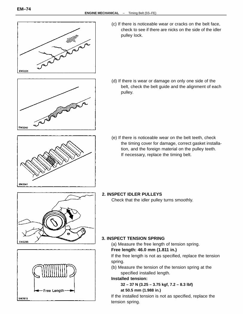
3. INSPECT TENSION SPRING(a) Measure the free length of tension spring.Free length: 46.0 mm (1.811 in.)If the free length is not as specified, replace the tensionspring.(b) Measure the tension of the tension spring at the
specified installed length.Installed tension:
32 – 37 N (3.25 – 3.75 kgf, 7.2 – 8.3 lbf)at 50.5 mm (1.988 in.)
If the installed tension is not as specified, replace thetension spring.
(e) If there is noticeable wear on the belt teeth, checkthe timing cover for damage, correct gasket installa-tion, and the foreign material on the pulley teeth.If necessary, replace the timing belt.
(d) If there is wear or damage on only one side of thebelt, check the belt guide and the alignment of eachpulley.
(c) If there is noticeable wear or cracks on the belt face,check to see if there are nicks on the side of the idlerpulley lock.
2. INSPECT IDLER PULLEYSCheck that the idler pulley turns smoothly.
–ENGINE MECHANICAL Timing Belt (5S–FE)EM–74
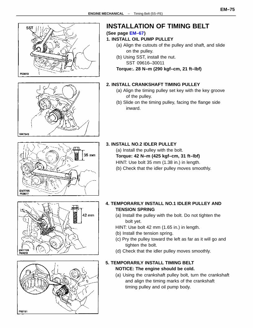
4. TEMPORARILY INSTALL NO.1 IDLER PULLEY ANDTENSION SPRING(a) Install the pulley with the bolt. Do not tighten the
bolt yet.HINT: Use bolt 42 mm (1.65 in.) in length.(b) Install the tension spring.(c) Pry the pulley toward the left as far as it will go and
tighten the bolt.(d) Check that the idler pulley moves smoothly.
INSTALLATION OF TIMING BELT(See page EM–67)1. INSTALL OIL PUMP PULLEY
(a) Align the cutouts of the pulley and shaft, and slideon the pulley.
(b) Using SST, install the nut.SST 09616–30011
Torque:. 28 N–m (290 kgf–cm, 21 ft–lbf)
5. TEMPORARILY INSTALL TIMING BELTNOTICE: The engine should be cold.(a) Using the crankshaft pulley bolt, turn the crankshaft
and align the timing marks of the crankshafttiming pulley and oil pump body.
3. INSTALL NO.2 IDLER PULLEY(a) Install the pulley with the bolt.Torque: 42 N–m (425 kgf–cm, 31 ft–lbf)HINT: Use bolt 35 mm (1.38 in.) in length.(b) Check that the idler pulley moves smoothly.
2. INSTALL CRANKSHAFT TIMING PULLEY(a) Align the timing pulley set key with the key groove
of the pulley.(b) Slide on the timing pulley, facing the flange side
inward.
–ENGINE MECHANICAL Timing Belt (5S–FE)EM–75
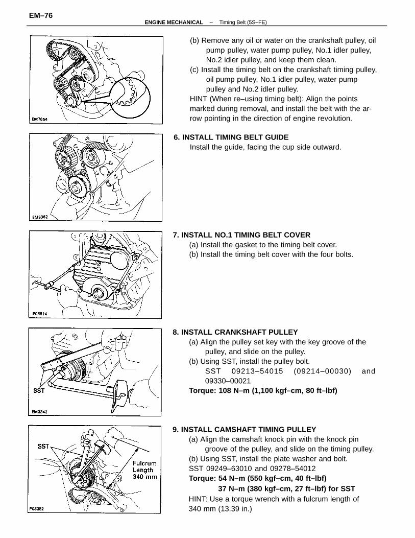
9. INSTALL CAMSHAFT TIMING PULLEY(a) Align the camshaft knock pin with the knock pin
groove of the pulley, and slide on the timing pulley.(b) Using SST, install the plate washer and bolt.SST 09249–63010 and 09278–54012Torque: 54 N–m (550 kgf–cm, 40 ft–lbf)
37 N–m (380 kgf–cm, 27 ft–lbf) for SSTHINT: Use a torque wrench with a fulcrum length of340 mm (13.39 in.)
(b) Remove any oil or water on the crankshaft pulley, oilpump pulley, water pump pulley, No.1 idler pulley,No.2 idler pulley, and keep them clean.
(c) Install the timing belt on the crankshaft timing pulley,oil pump pulley, No.1 idler pulley, water pumppulley and No.2 idler pulley.
HINT (When re–using timing belt): Align the pointsmarked during removal, and install the belt with the ar-row pointing in the direction of engine revolution.
8. INSTALL CRANKSHAFT PULLEY(a) Align the pulley set key with the key groove of the
pulley, and slide on the pulley.(b) Using SST, install the pulley bolt.
SST 09213–54015 (09214–00030) and09330–00021
Torque: 108 N–m (1,100 kgf–cm, 80 ft–lbf)
7. INSTALL NO.1 TIMING BELT COVER(a) Install the gasket to the timing belt cover.(b) Install the timing belt cover with the four bolts.
6. INSTALL TIMING BELT GUIDEInstall the guide, facing the cup side outward.
–ENGINE MECHANICAL Timing Belt (5S–FE)EM–76

11. INSTALL TIMING BELTHINT (When re–using timing belt):
• Check that the matchmark on the timing belt matchesthe end of the No.1 timing belt cover.
If the matchmark does not align, shift the meshing of thetiming belt and crankshaft timing pulley until they align.(See page EM–71)
(a) Remove any oil or water on the camshaft timingpulley, and keep it clean.
(b) Install the timing belt, and checking the tensionbetween the crankshaft timing pulley and camshafttiming pulley.
(b) Using SST, turn the camshaft, and align the hole ofthe camshaft timing pulley with the timing mark ofthe bearing cap.SST 09278–54012
10. SET NO.1 CYLINDER–TO TDC/COMPRESSION(a) Turn the crankshaft pulley, and align its groove with
timing mark ”0” of the No.1 timing belt cover.
• Align the matchmarks of the timing belt and camshafttiming pulley.
–ENGINE MECHANICAL Timing Belt (5S–FE)EM–77

(d) Slowly turn the crankshaft pulley 1 7/8 revolutions,and align its groove with the mark at BTDC 45° (forNo.1 cylinder) of the No.1 timing belt cover.
NOTICE: Always turn the crankshaft clockwise.
(c) Check that each pulley aligns with the timing marksas shown in the illustration.If the timing marks do not align, remove the timing beltand reinstall it.
(e) Torque the mounting bolt of the No.1 idler pulley.Torque: 42 N–m (425 kgf–cm, 31 ft–lbf)(f) Recheck the valve timing.
(b) Slowly turn the crankshaft pulley two revolutionsfrom TDC to TDC.
NOTICE: Always turn the crankshaft clockwise.
12. CHECK VALVE TIMING(a) Loosen the No.1 idler pulley bolt 1 /2 turn.
–ENGINE MECHANICAL Timing Belt (5S–FE)EM–78

17. INSTALL RH ENGINE MOUNTING INSULATORInstall the mounting insulator with the through bolt andtwo nuts.Torque:Nut 52 N–m (530 kgf–cm, 38 ft–lbf)Through bolt 87 N–m (890 kgf–cm, 64 ft–lbf)
18. INSTALL PS RESERVOIR TANK TO BRACKET
13. INSTALL NO.2 TIMING BELT COVER(a) Disconnect the engine Wire protector between the
No.3 timing belt cover and cylinder head cover.(b) Install the two gaskets to the No.1 and No.2 belt
covers.(c) Install the belt cover with the five bolts.
14. INSTALL ENGINE WIRE TO ALTERNATOR BRACKETAND ADJUSTING BARInstall the engine wire with the two bolts.
15. INSTALL SPARK PLUGSTorque: 18 N–m (180 kgf–cm, 13 ft–lbf)
16. INSTALL RH ENGINE MOUNTING BRACKETInstall the bracket with the three bolts.Torque: 52 N–m (530 kgf–cm, 38 ft–lbf)
(d) Install the two clamps of the engine wire protectorto each bolt.
–ENGINE MECHANICAL Timing Belt (5S–FE)EM–79

22. INSTALL ALTERNATOR (See page CH–25)23. (w/ CRUISE CONTROL SYSTEM (w/o ABS)
INSTALL CRUISE CONTROL ACTUATOR(See step 33 on page EM–309)
24. INSTALL RH FRONT WHEEL25. CONNECT CABLE TO NEGATIVE TERMINAL OF
BATTERY26. CHECK AND ADJUST DRIVE BELTS
Adjust the drive belts.Drive belt tension:
Alternatorw/ A/C New belt 165 ± 10 lbf
Used belt 110 ± 10 lbfw/o A/C New belt 125 ± 25 lbf
Used belt 95 ± 20 lbfPS pump New belt 125 ± 10 lbf
Used belt 80 ± 20 lbf
27. INSTALL RH ENGINE UNDER COVER
19. INSTALL RH ENGINE MOUNTING STAYInstall the mounting stay with the bolt and nut.Torque: 73 N–m (740 kgf–cm, 54 ft–lbf)
20. CONNECT GROUND CONNECTOR TO GROUND WIREON RH FENDER APRON
21. INSTALL PS DRIVE BELTInstall the drive belt with the pivot bolt and adjustingbolt.
–ENGINE MECHANICAL Timing Belt (5S–FE)EM–80