timelapse camera slide version 2
TRANSCRIPT

Timelapse Camera Slide v2A while ago I posted an article describing a Camera slide constructed from the bits of a discontinued 3DPrinter project I was working on. It worked, but not very well. For the sake of completeness you can find the project described here (http://www.techmonkeybusiness.com/timelapse-camera-slide-from-a-3d-printer.html) The drive screw was long and vulnerable to getting bent .... even to the point of it not being possible to buy ones from the hardware store that didn't have some slight bow to it. This bend created a funky waggle to the CameraSlide's traveller which looked pretty goofy when any timelapse video recorded using the device was played back at 25 frames a second. So I set about redesiging it with some other ex-3DPrinter bits and using a completely different approach.
This new design uses a pulley around which a string or cord could be wrapped. This allows the CameraSlidetraveller to winch itself along smoothly and easily. It is also less inclined to jam because the pulley is centrally located and allows the traveller to better follow the tracks.
This article describes the CameraSlide version 2 project and provides all necessary files and things to build it.
Camera Slide Structural HardwareYou may wonder about the components and why they are not better optimised for a camera slide project. AsI mentioned above, the project was conceived to make use of some of the many 3D printed bits that I had to hand from the aborted 3DPrinter project I had designs and pretty much built. I wanted to avoid printing any more bits. As it happens I have redesigned some of the bits for the project for anyone who is looking to buildthe CamerSlide from scratch. The same applies to some of the MDF panel shapes, where I have used what I had rather than purposefully cut some more. You will find that the photograph of my CameraSlide differs slightly from the design I am presenting here.
Ex 3D Printer Grab Bag.

Here is a photo of the CameraSlide Traveller.
And a shot of the underside showing the “winch drum”
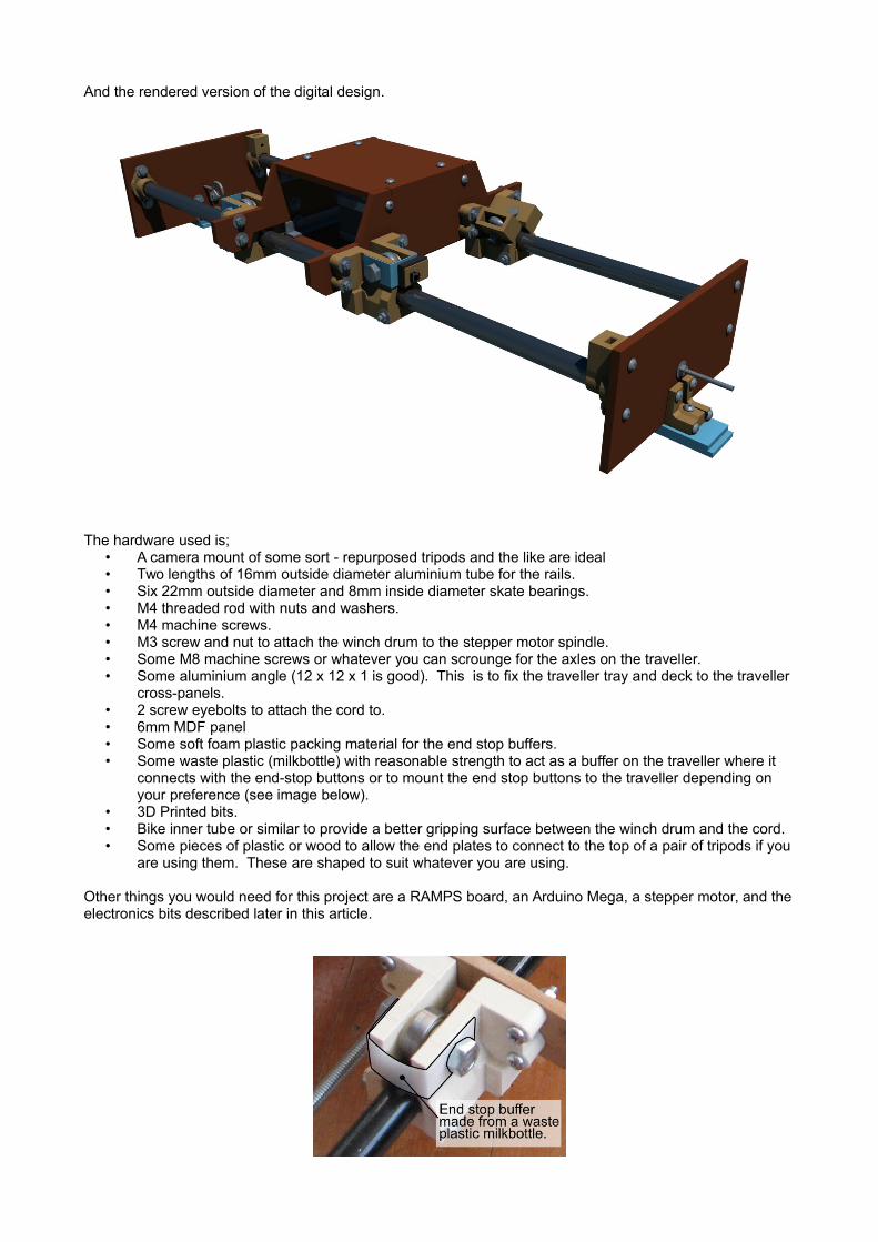
And the rendered version of the digital design.
The hardware used is;• A camera mount of some sort - repurposed tripods and the like are ideal• Two lengths of 16mm outside diameter aluminium tube for the rails.• Six 22mm outside diameter and 8mm inside diameter skate bearings.• M4 threaded rod with nuts and washers.• M4 machine screws.• M3 screw and nut to attach the winch drum to the stepper motor spindle.• Some M8 machine screws or whatever you can scrounge for the axles on the traveller.• Some aluminium angle (12 x 12 x 1 is good). This is to fix the traveller tray and deck to the traveller
cross-panels.• 2 screw eyebolts to attach the cord to.• 6mm MDF panel• Some soft foam plastic packing material for the end stop buffers.• Some waste plastic (milkbottle) with reasonable strength to act as a buffer on the traveller where it
connects with the end-stop buttons or to mount the end stop buttons to the traveller depending on your preference (see image below).
• 3D Printed bits.• Bike inner tube or similar to provide a better gripping surface between the winch drum and the cord.• Some pieces of plastic or wood to allow the end plates to connect to the top of a pair of tripods if you
are using them. These are shaped to suit whatever you are using.
Other things you would need for this project are a RAMPS board, an Arduino Mega, a stepper motor, and theelectronics bits described later in this article.

The 3D Printed parts can be found within the Blender 2.57 assembly model and collection of STL model files that can be downloaded from here: Blender model and the STLs. There is also an obj version available here.
I have included some drawings of the wooden panels for the sake of completion. I just re-cut the ones I had made for the 3D printer, and so the camera dolly appearing in the photo is a little rougher than if it was built from scratch using the files on this webpage. The panel drawings in a pdf format can be found here: A4 and A3.
The MDF panel drawings show where most of the holes needs to be drilled but some are left out because this will vary depending on what motors and camera support arrangements you are using.
Electronic HardwareBecause they were left over from the aborted 3D printer build I had a RAMPS board, Arduino Mega, stepper motors, and end stops, to build and run the camera dolly. Because I was not intending to control the camera pitch, tilt, and pan, the RAMPS / Arduino Mega combination would not be working very hard at all. Apart from changing the pin assignments, an Arduino UNO or Arduino Nano driving an Easystepper or Pololu stepper driver could easily run this system.
To code the Arduino Mega, I pulled out the schematics of the RAMPS board from the Reprap.org website and figured out which pins I needed to use. In the end, the pin assignments were:
Endstop 1 - RAMPS Z-MAX D19 (Interrupt 2 – on my Arduino Mega this was INT4)Endstop 2 - RAMPS Z-MIN D18 (Interrupt 3 – on my Arduino Mega this was INT5)Stop button - RAMPS Y-MAX D15 (Supposedly this was Interrupt 9, but in reality my Arduino Mega did not recognise it as an interrupt)
RAMPS AUX-4 ConnectionsStart Fast Reposition button direction 0 - D33Start Fast Reposition button direction 1 - D35Start Timelapse Travel button direction 0 - D37Start Timelapse Travel button direction 1 - D39Transit speed setting button up - D17Transit speed setting button down - D16
TM1637 DisplayCLK - D25DIO - D23
Indicator LEDs on pins D27, D29, and D31
5V supply to perfboard panel from the RAMPS Y-MAX connectionGND to perfboard panel from the RAMPS Y-MAX connection
Stepper Control Pins:Step - D26Dir – D28Enable - D24
The control board is relatively simple and consists of a number of buttons with 10kΩ pull up resistors (The pin is high ordinarily and goes low when triggered), several LEDs and a TM1637 based display. The display is used to show the time in minutes for a 1 metre traverse when running in timelapse mode. The buttons on pins D17 and D16 are used to set this traverse time.
The circuit is shown below and where it attaches to the RAMPS board.
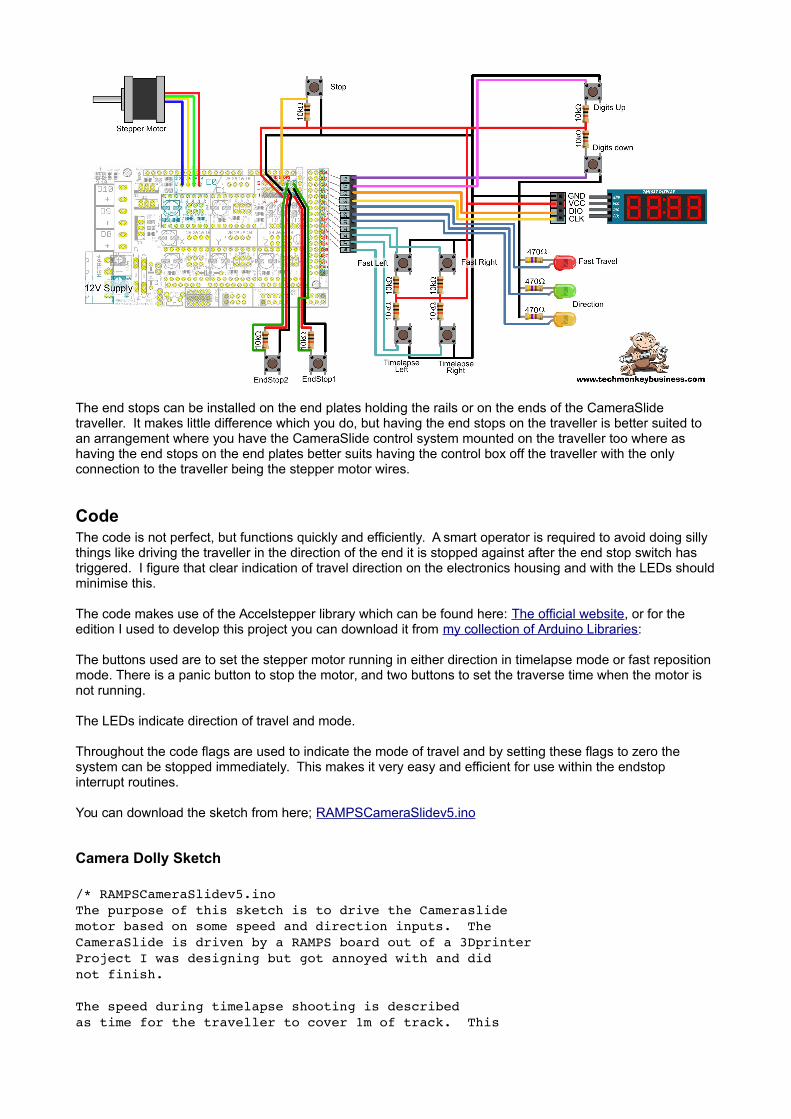
The end stops can be installed on the end plates holding the rails or on the ends of the CameraSlide traveller. It makes little difference which you do, but having the end stops on the traveller is better suited to an arrangement where you have the CameraSlide control system mounted on the traveller too where as having the end stops on the end plates better suits having the control box off the traveller with the only connection to the traveller being the stepper motor wires.
CodeThe code is not perfect, but functions quickly and efficiently. A smart operator is required to avoid doing silly things like driving the traveller in the direction of the end it is stopped against after the end stop switch has triggered. I figure that clear indication of travel direction on the electronics housing and with the LEDs shouldminimise this.
The code makes use of the Accelstepper library which can be found here: The official website, or for the edition I used to develop this project you can download it from my collection of Arduino Libraries:
The buttons used are to set the stepper motor running in either direction in timelapse mode or fast reposition mode. There is a panic button to stop the motor, and two buttons to set the traverse time when the motor is not running.
The LEDs indicate direction of travel and mode.
Throughout the code flags are used to indicate the mode of travel and by setting these flags to zero the system can be stopped immediately. This makes it very easy and efficient for use within the endstop interrupt routines.
You can download the sketch from here; RAMPSCameraSlidev5.ino
Camera Dolly Sketch
/* RAMPSCameraSlidev5.inoThe purpose of this sketch is to drive the Cameraslidemotor based on some speed and direction inputs. TheCameraSlide is driven by a RAMPS board out of a 3DprinterProject I was designing but got annoyed with and didnot finish.
The speed during timelapse shooting is describedas time for the traveller to cover 1m of track. This

is displayed on a 4Digit display that uses theTM1637 driver chip.
Obviously seeing as we are using a RAMPS board we areusing an Arduino Mega. It's all a bit overkill but thatis what I had to hand.
Pin assignments are:Endstop 1 RAMPS ZMAX D19 (Interrupt 2)Endstop 2 RAMPS ZMIN D18 (Interrupt 3)Stop button RAMPS YMAX D15 (Interrupt 9)
Note: On my MEGA, the interrupts do not match the official assignments. RAMPS ZMAX D19 is INT 4and RAMPS ZMIN D18 is INT 5.Note also that D15 does not appear to interrupt anywayso this edition introduces an if statement within the schemeto try to stop it.
RAMPS AUX4 ConnectionsStart Fast Reposition button direction 0 D33Start Fast Reposition button direction 1 D35Start Timelapse Travel button direction 0 D37Start Timelapse Travel button direction 1 D39Transit speed setting button up D17Transit speed setting button down D16
TM1637 DisplayCLK D25DIO D23
Indicator LEDs on pins D27, D29, and D31
5V supply to breadboardGND to breadboard
Stepper Control Pins are on the RAMPS Extruder E0:Step D26Dir D28Enable D24
*/
#include <TM1637Display.h>
#include <AccelStepper.h>// Define the stepper and the pins it will use//The numbers are (don't know, Step, Dir)
AccelStepper stepper1(1, 26, 28);
const int CLK = 25;const int DIO = 23;
const int Estop1 = 18;const int Estop2 = 19;const int Allstop = 15;
const int FastRepButton1 = 33;

const int FastRepButton2 = 35;const int RunButton1 = 37;const int RunButton2 = 39;const int AdjTimeup = 17;const int AdjTimedn = 16;const int LEDcol1 = 31; //LED to indicate Fast direction 1const int LEDcol2 = 29; //LED to indicate Fast direction 2const int LEDFast = 27; //LED to indicate Fast travel.
volatile boolean Fast = 0; //Flag for repositioningvolatile boolean RunMe = 0; //Flag for timelapse photography run.volatile boolean dir = 0; //Flag for direction to run.
int TravTime = 60; //default time (minutes)to traverse 1 metre of trackconst float DriveDiam = 18.5; //diameter of the winch drumconst int StepSize = 400; //Steps per rotationconst int MSteps = 8; //Microsteps per step fudgefactorconst long TotSteps = 1000/(3.14 * DriveDiam) * StepSize * MSteps;// TotSteps is the total steps for 1 metre of travelint TravSpeed = 0; // Steps per second
int FastSpeed = 8000; //Speed for the fast traverseint FastSpdDir = 1; //Direction multiplier for fast traverse direction.
TM1637Display display(CLK, DIO); //set up the 4Digit Display.
void setup(){ display.setBrightness(0x0a); pinMode(Estop1, INPUT); pinMode(Estop2, INPUT); pinMode(Allstop, INPUT); pinMode(FastRepButton1, INPUT); pinMode(FastRepButton2, INPUT); pinMode(RunButton1, INPUT); pinMode(RunButton2, INPUT); pinMode(AdjTimeup, INPUT); pinMode(AdjTimedn, INPUT); pinMode(LEDcol1,OUTPUT); pinMode(LEDcol2,OUTPUT); pinMode(LEDFast,OUTPUT);
attachInterrupt(5,StopSys,FALLING); //D18 Pin * attachInterrupt(4,StopSys,FALLING); //D19 Pin * // * Note interrupts different from official ones. // don't ask me why this is. // The only AccelStepper value we have to set here is the max speeed, which ishigher than we'll ever go stepper1.setMaxSpeed(10000.0); stepper1.setAcceleration(100); digitalWrite(LEDcol1,LOW); digitalWrite(LEDcol2,LOW); digitalWrite(LEDFast,LOW); }
void loop(){ display.showNumberDec(TravTime); //Display the traverse time; TravSpeed = int(float(TotSteps/(TravTime*60))); //The control buttons are used to set the flags which determine //the mode of operation and the direction. if(digitalRead(FastRepButton1) == LOW) { RunMe = 0; //Disable the Timelapse mode Fast = 1; //enable the fast travel mode dir = 0; //Set the direction to 0 stepper1.setSpeed(FastSpeed); //Sets the speed. } if(digitalRead(FastRepButton2) == LOW) { RunMe = 0; //Disable the Timelapse mode Fast = 1; //enable the fast travel mode dir = 1; //Set the direction to 1 stepper1.setSpeed(FastSpeed); //Sets the speed in negative direction. } if(digitalRead(RunButton1) == LOW) { RunMe = 1; //enable the Timelapse mode Fast = 0; //disable the fast travel mode dir = 0; //Set the direction to 0 stepper1.setSpeed(TravSpeed); //Sets the speed for slow traverse. } if(digitalRead(RunButton2) == LOW) { RunMe = 1; //enable the Timelapse mode Fast = 0; //disable the fast travel mode dir = 1; //Set the direction to 1 stepper1.setSpeed(TravSpeed); //Sets the speed for slow traverse. } //LED will be used to indicate that the motor is running //and the direction it is going. digitalWrite(LEDcol1,dir); //The LED pins hold their values digitalWrite(LEDcol2,!dir); //while the other processes digitalWrite(LEDFast,Fast); // are running. while(Fast == 1 | RunMe ==1) { stepper1.runSpeed(); if(digitalRead(Allstop) == LOW) { Fast = 0; //If panic button hit then stop everything. RunMe = 0; } } //If the platform is not in either fast relocate or //Timelapse shooting mode, then allow the Traverse time //to be set. if(RunMe == 0 && Fast == 0) {
if(digitalRead(AdjTimeup) == LOW) { TravTime = TravTime +1; //Increase Traverse Time by 1 minute delay(10); //Just to slow things a little. } if(digitalRead(AdjTimedn) == LOW) { TravTime = TravTime 1; //Increase Traverse Time by 1 minute if(TravTime <= 1) // No negative time eh. { TravTime = 1; } delay(10); //Just to slow things a little. } }
}
void StopSys(){ Fast = 0; RunMe = 0; //Stop the motor.}
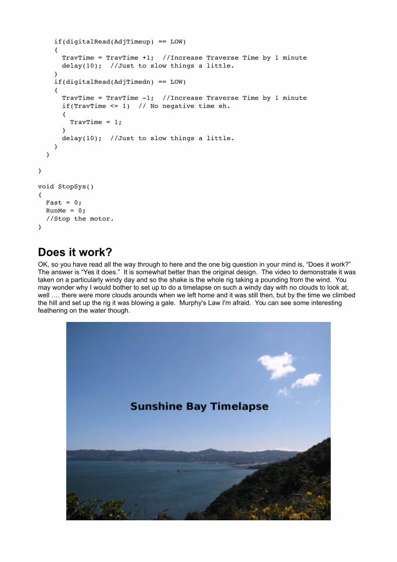
Does it work?OK, so you have read all the way through to here and the one big question in your mind is, “Does it work?”The answer is “Yes it does.” It is somewhat better than the original design. The video to demonstrate it was taken on a particularly windy day and so the shake is the whole rig taking a pounding from the wind. You may wonder why I would bother to set up to do a timelapse on such a windy day with no clouds to look at, well …. there were more clouds arounds when we left home and it was still then, but by the time we climbed the hill and set up the rig it was blowing a gale. Murphy's Law I'm afraid. You can see some interesting feathering on the water though.

Hamish Trolove
www.techmonkeybusiness.comwww.techmonkeybusiness.com
The RAMPS camera slide project described above is provided by Hamish Trolove under a creative commonslicense.
Creative Commons Attribution-NonCommercial-ShareAlike 4.0 International License.