time-triggered ethernet – a powerful network solution ... · with ethernet being used as a...
TRANSCRIPT

1 Deterministic Real-Time Ethernet Platform Page
Ensuring Reliable Networks
Time-Triggered Ethernet – A Powerful Network Solution for Multiple Purpose
Ethernet after 30 years of use continues to spread its reach and find its way into new application domains. With Ethernet being used as a universal network solution in office and web applications and in production facilities, it is now finding a home in the toughest of fields of application, in real-time safety-critical systems such as Automotive & Aerospace. When Ethernet was first developed, applications with time-critical, deterministic or safety-relevant requirements were not taken into account. Time-Triggered Ethernet directly addresses this issue and extends classical Ethernet with powerful services to meet the requirements of fully deterministic communication, providing fault tolerant synchronization services, guaranteed constant latency for multi-hop communication routes in a network, and partitioning/protection of network traffic.
From Ethernet to Time-Triggered Ethernet Over the last few years several solutions were developed to adapt Ethernet for new application domains. Its focus has been on the use of Ethernet for real-time tasks in industrial environments (Industrial Ethernet) for usage in safe applications. Several solutions like Profibus, EtherCAT, EthernetIP, PRP are competing for recognition in industrial automation alone. Additional adaptations have been made to meet special requirements for Ethernet in other areas, e.g. LXI in measurement technology or AFDX in the aerospace industry. However these adapted Ethernet solutions have limits when it comes to combining them with standard (classical) Ethernet networks and devices. The scalability of the adapted Ethernet solutions for different industries is also limited as the network solution is tailored for a specific application area. A trend that is developing in many industries is the attempt to reduce the number of networks and to cut costs for effort and resources; therefore converged networks carrying a mix of critical and noncritical traffic are increasingly used, but usually require some trade-offs in terms of utilization or flexibility.
Taking a look at networking technologies in general, one can distinguish between closed, statically configured networks and open, dynamic networks allowing free-form communication. Whereas statically configured communication networks – most are using fieldbus-specific technology – enable reliable data transmission in real-time (to different extents), free-form communication networks perform only on a best-effort basis, i.e., there is no guarantee if and when data messages are transmitted. Additional Quality-of-Service mechanisms are implemented on top of free-form communication systems to provide statistical/probabilistic guarantees, but the main issue which remains with these systems is that they can largely fail to provide deterministic guarantees for nontrivial network setups.
Time-Triggered Ethernet combines the proven fault-tolerance and real-time mechanisms of the time-triggered technology that enable deterministic communication, with mechanisms that allow flexible and free-form communication compatible with legacy Ethernet, and therefore it is suited for different types of
Copyright © TTTech Computertechnik AG. All rights reserved.

2 Deterministic Real-Time Ethernet Platform Page
Ensuring Reliable Networks
applications. Time-Triggered Ethernet combines together the high flexibility of free-form systems and the reliability and determinism of statically configured systems (see Figure 1).
Time-Triggered Ethernet Design Objectives Time-Triggered Ethernet enables the communication of applications with different criticality requirements by way of Ethernet. Conventional PCs, office devices, multimedia systems, real-time systems and safety-critical systems can be connected to the same network. In order to guarantee this Time-Triggered Ethernet is designed to be compatible to standards like IEEE Ethernet 802.3.
Time-Triggered Ethernet can be used as a single real-time network and backbone network solution in application domains like aerospace. In this case entertainment system, electronic navigation and guidance system, and internet access in passenger seats can be integrated in a single network and therefore save the cost and weight for separated wires and network components. In order to make that available, Time-Triggered Ethernet must guarantee the partitioning at network level, i.e., that critical applications get the required network service to provide the specified functionality and that different applications do not affect each other in unspecified manner. On the other hand the fault-handling and partitioning mechanisms shall avoid the propagation of faults in the system and prevent potential intruders from unauthorized access to network resources.
Fig. 1: Time-Triggered Ethernet combines closed-world and open-world systems on the basis of IEEE 802.3 Ethernet standards
Copyright © TTTech Computertechnik AG. All rights reserved.

3 Deterministic Real-Time Ethernet Platform Page
Ensuring Reliable Networks
Time-Triggered Ethernet is a scalable technology and allows development of critical system parts according to fail-safe or fail-operational application requirements. Time-Triggered Ethernet networks can be configured in order to satisfy the requirements for higher safety (for fail-safe applications) and/or high-availability (for fail-operational applications). In fail-safe applications the system must reach a safe state in case of a failure. In fail-operational applications the system must remain fully functional even if a failure occurs (supporting a single or double fault hypothesis).
Time-Triggered Ethernet can be used to implement critical applications that enable distributed control applications where usually deterministic communication and fixed communication latencies in real-time communication are an advantage. The traffic generated by critical applications (critical messages) will always take precedence over traffic generated by non-critical applications (non-critical messages) in Time-Triggered Ethernet. The temporal behavior of the critical messages is predictable (deterministic) and can be configured depending on the required quality. An existing critical application need not to be changed in case the network is extended (because of the change of other applications) in terms of functionality (updates) or scalability (additional components).
Time-Triggered Ethernet provides a variety of network services such as a deterministic message transport service, fault-tolerant clock synchronization service, a startup service and clique detection and diagnostic services. As Time-Triggered Ethernet is used in safety–critical applications, the critical mechanism of Time-Triggered Ethernet like clock synchronization and start-up are formally verified.
Time-Triggered Ethernet operates on the OSI layer 2, and it can support various physical layers. Time-Triggered Ethernet can operate with any physical layer that provides constant communication latency for transmission of data over the physical link. Wireless communication is not a suitable choice, as the transmission latency at the physical level depends on the signal strength.
Time-Triggered Ethernet System Properties Time-Triggered Ethernet implements time-triggered communication mechanisms to provide a deterministic communication service over Ethernet. These time-triggered mechanisms establish and maintain a global time, which is realized by the synchronization of the local clocks of all Time-Triggered Ethernet devices. The global time is used as basis for implementing temporal partitioning, precise diagnosis, efficient resource utilization, or composability. The global time service of Time-Triggered Ethernet can be compared with the IEEE 1588 Precision Time Protocol, but uses multiple active “grandmaster clocks” to form a fault tolerant synchronization group with no need for re-election in case of an active grandmaster clock failure.
Temporal Partitioning: The global time is used to implement a fault isolation (temporal firewall) mechanism, in order to prevent that a faulty device affects the network operation of other devices. Based on the global time, the Time-Triggered Ethernet -Switch can block the traffic generated by faulty components, and prevent untimely messages to disrupt the determinism of critical traffic flows. Moreover Time-Triggered Ethernet
Copyright © TTTech Computertechnik AG. All rights reserved.
4 Deterministic Real-Time Ethernet Platform Page
Ensuring Reliable Networks
switches operate in a fail-silent manner, i.e., it operates either correctly, or does not provide any functionality (high-integrity designs).
Efficient Resource Utilization: The global time contributes to efficient resource utilization in several ways. Time-triggered communication allows implementation of network components with minimal memory buffers as the time-triggered communication schedule is free of conflicts. Hence, switches do not have to implement large buffer space for handling bursts of messages that have to be delivered over the same physical link.
Precise Diagnosis: The global time stamping service simplifies the process of reconstruction of a chain of distributed events. On the other hand, the synchronous capturing of sensor values allows building snapshots of the state of a system that is physically distributed even over several kilometers (oil and gas platforms).
Composability: The global time allows the specification of device interfaces not only in the value domain, but also in the temporal domain. This means that already during the design process of devices, the access pattern to the communication network can be defined for specific services. The devices can then be developed in parallel activities. Upon integration of the individual devices, it is guaranteed that prior services are stable and that the individual devices operate once they are integrated.
Dataflow Options in Time-Triggered Ethernet
In order to support integration of applications with different real-time and safety requirements in a single network, Time-Triggered Ethernet supports three different traffic classes:
• time-triggered (TT) traffic – is sent in a time-triggered way, i.e. each Time-Triggered Ethernet sender node has a transmit schedule, and each TTE-Switch has a receive and forward schedule. This traffic is sent over the network with constant communication latency and small and bounded jitter.
• rate-constrained (RC) traffic – is sent with a bounded latency and jitter ensuring lossless communication. Each Time-Triggered Ethernet sender node gets a reserved bandwidth for transmitting messages with the RC traffic. No clock synchronization is required for RC message exchange.
• best-effort (BE) traffic – traffic with no timing guarantees. BE traffic class compatible with the IEEE 802.3 standard Ethernet traffic.
Copyright © TTTech Computertechnik AG. All rights reserved.
5 Deterministic Real-Time Ethernet Platform Page
Ensuring Reliable Networks
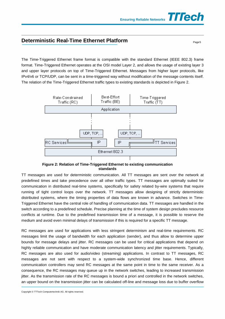
The Time-Triggered Ethernet frame format is compatible with the standard Ethernet (IEEE 802.3) frame format. Time-Triggered Ethernet operates at the OSI model Layer 2, and allows the usage of existing layer 3 and upper layer protocols on top of Time-Triggered Ethernet. Messages from higher layer protocols, like IPv4/v6 or TCP/UDP, can be sent in a time-triggered way without modification of the message contents itself. The relation of the Time-Triggered Ethernet traffic types to existing standards is depicted in Figure 2.
TT messages are used for deterministic communication. All TT messages are sent over the network at predefined times and take precedence over all other traffic types. TT messages are optimally suited for communication in distributed real-time systems, specifically for safety related by-wire systems that require running of tight control loops over the network. TT messages allow designing of strictly deterministic distributed systems, where the timing properties of data flows are known in advance. Switches in Time-Triggered Ethernet have the central role of handling of communication data. TT messages are handled in the switch according to a predefined schedule. Precise planning at the time of system design precludes resource conflicts at runtime. Due to the predefined transmission time of a message, it is possible to reserve the medium and avoid even minimal delays of transmission if this is required for a specific TT message.
RC messages are used for applications with less stringent determinism and real-time requirements. RC messages limit the usage of bandwidth for each application (sender), and thus allow to determine upper bounds for message delays and jitter. RC messages can be used for critical applications that depend on highly reliable communication and have moderate communication latency and jitter requirements. Typically, RC messages are also used for audio/video (streaming) applications. In contrast to TT messages, RC messages are not sent with respect to a system-wide synchronized time base. Hence, different communication controllers may send RC messages at the same point in time to the same receiver. As a consequence, the RC messages may queue up in the network switches, leading to increased transmission jitter. As the transmission rate of the RC messages is bound a priori and controlled in the network switches, an upper bound on the transmission jitter can be calculated off-line and message loss due to buffer overflow
Figure 2: Relation of Time-Triggered Ethernet to existing communication standards
Copyright © TTTech Computertechnik AG. All rights reserved.

6 Deterministic Real-Time Ethernet Platform Page
Ensuring Reliable Networks
or message timeouts is prevented. If TT messages are to be transmitted via the same outgoing port of a switch at the same time, the TT messages take priority over the RC messages. TT messages can delay RC messages. RC messages are transmitted when no planned transmission of TT messages is pending and the sender observes the minimal transmission distance. The switch is responsible for arranging RC messages queued at an outgoing port.
BE messages follow a method that is well-known in classical Ethernet networks. The network handles the messages in the best-effort manner, and therefore there is no guarantee whether and when these messages will be transmitted. BE messages use the remaining bandwidth of the network and have less priority than TT and RC messages. All legacy Ethernet traffic (e.g. internet protocols) can be mapped to this service class. RC and TT messages take precedence over BE messages at the same outgoing port of a switch. The switch uses the remaining bandwidth for BE messages if no TT or RC messages are to be transmitted. BE messages are transmitted after all pending RC messages, thus the remaining bandwidth is exploited in an optimal way. Tools are used to design and verify a Time-Triggered Ethernet system in advance. This ensures that the bandwidth for TT and RC messages is always sufficient according to the requirements of the application and interrupts are reduced to a minimum. Later incremental changes of the system configuration are possible.
Time-Triggered Ethernet components implement partitioning between non-critical BE traffic, RC traffic and TT traffic, and the Time-Triggered Ethernet Switches implement the key mechanisms for integrating traffic
flows (see Figure 3).
Figure 3: integration of different data flows
Copyright © TTTech Computertechnik AG. All rights reserved.

7 Deterministic Real-Time Ethernet Platform Page
Ensuring Reliable Networks
Time-Triggered Ethernet as Transparent Synchronization Protocol Time-Triggered Ethernet is a transparent synchronization protocol, i.e., it is able to co-exist with other traffic, potentially legacy traffic, on the same physical communication network. For reasons of fault tolerance a multitude of devices can be configured to generate synchronization messages. The Time-Triggered Ethernet clock synchronization protocol is performed based on dedicated messages termed protocol control frames (PCF).
Time-Triggered Ethernet implements the transparent clock mechanism that enables the calculation of the permanence point in time, which allows re-establishing the send order of messages in a receiver. The transparent clock mechanism is used to calculate the dynamic delay on the transmission of synchronization messages, and to add this dynamic delay into a dedicated data field in the synchronization messages used for the synchronization protocol. This mechanism is similar to the IEEE 1588 transparent clock synchronization mechanisms. IEEE 1588 specifies a synchronization protocol that is widely used in different Ethernet technology variants. Native IEEE 1588 enabled components can be connected in a Time-Triggered Ethernet network and they can synchronize their clocks by using the IEEE 1588 protocol over the Time-Triggered Ethernet switches.
The application of transparent clock mechanism allows a precise re-establishment of the temporal order of synchronization messages. In a first step the worst case delay is calculated off-line. In a second step, each synchronization message is delayed for ”worst case delay minus dynamic delay” upon reception of the synchronization message, where the dynamic delay is the delay added to the synchronization message, as the synchronization message flows through the communication channel. This point after the reception point in time will be called the permanence point in time. The re-establishment of the send order of synchronization messages is required for any fault-masking synchronization protocol that ensures synchronization of local clocks in a distributed computer network.
Synchronization Clock synchronization among all participants is crucial for the transmission of TT messages. Time-Triggered Ethernet components always transmit clock synchronization messages to keep the clocks of the end systems and switches in synchronization. For this purpose Time-Triggered Ethernet relies on a redundant hierarchical master-slave method that has a distributed fault-tolerant majority of master nodes and master switches to provide the time in the system. This method is unique for Time-Triggered Ethernet and can be combined with other mechanisms such IEEE 1588.
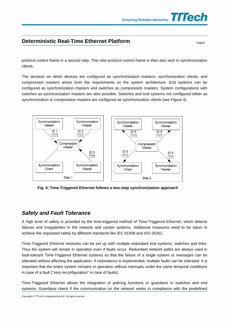
Time-Triggered Ethernet takes a two-step approach to synchronization. In the first step, the synchronization masters send protocol control frames to the compression masters. The compression masters then calculate an averaging value from the relative arrival times of these protocol control frames and send out a new
Copyright © TTTech Computertechnik AG. All rights reserved.
8 Deterministic Real-Time Ethernet Platform Page
Ensuring Reliable Networks
protocol control frame in a second step. This new protocol control frame is then also sent to synchronization clients.
The decision on which devices are configured as synchronization masters, synchronization clients, and compression masters arises from the requirements on the system architecture. End systems can be configured as synchronization masters and switches as compression masters. System configurations with switches as synchronization masters are also possible. Switches and end systems not configured either as synchronization or compression masters are configured as synchronization clients (see Figure 4).
Safety and Fault Tolerance A high level of safety is provided by the time-triggered method of Time-Triggered Ethernet, which detects failures and irregularities in the network and certain systems. Additional measures need to be taken to achieve the requested safety by different standards like IEC 61508 and ISO 26262.
Time-Triggered Ethernet networks can be set up with multiple redundant end systems, switches and links. Thus the system will remain in operation even if faults occur. Redundant network paths are always used in fault-tolerant Time-Triggered Ethernet systems so that the failure of a single system or messages can be tolerated without affecting the application. If redundancy is implemented, multiple faults can be tolerated. It is important that the entire system remains in operation without interrupts under the same temporal conditions in case of a fault (“zero reconfiguration” in case of faults).
Time-Triggered Ethernet allows the integration of policing functions or guardians in switches and end systems. Guardians check if the communication on the network works in compliance with the predefined
Fig. 4: Time-Triggered Ethernet follows a two-step synchronization approach
Copyright © TTTech Computertechnik AG. All rights reserved.

9 Deterministic Real-Time Ethernet Platform Page
Ensuring Reliable Networks
parameters. If faulty systems occupy the bandwidth on network links, the guardian will drop the faulty messages on the receiving port of that link. Active redundant guardians can be implemented to achieve a highly-available system (see Figure 5).
Fig. 5: Time-Triggered Ethernet provides implicit fault tolerance mechanisms
Depending on its implementation, a Time-Triggered Ethernet end system can support communication over one, two or three channels. In Figure 5 Time-Triggered Ethernet end systems with two communication channels are used (denoted as TTE) in one part of the network and other Time-Triggered Ethernet end systems (denoted as TTE-1) with one communication channel in other part of the network. Standard Ethernet components can be also used in a Time-Triggered Ethernet network. In Figure 5 these are denoted as “Eth”.
Supported Topologies Time-Triggered Ethernet support full duplex communication with two basic topologies, star and ring. In the star topology, configurations with one two and three channels are possible. A communication channel in Time-Triggered Ethernet with star topology defines the physical connection between any two Time-Triggered Ethernet end systems.
Copyright © TTTech Computertechnik AG. All rights reserved.

10 Deterministic Real-Time Ethernet Platform Page
Ensuring Reliable Networks
Figure 6: Star topology with single and dual channel
The left-hand side of Figure 6 shows single channel configuration, and the right-hand side shows a dual channel configuration. In case of dual channel, the sending Time-Triggered Ethernet end system transmit identical copies of critical traffic (TT and RC) over the two redundant channels, and the receiving Time-Triggered Ethernet end systems will pass over only one copy of the redundant frames to the application layer, thus making the network redundancy completely transparent to the application.
In the ring topology only Time-Triggered Ethernet -switches are connected in the ring, the end systems are connected to the switches. The advantage of the ring topology is the toleration of the link failures among the switches. Figure 7 show a possible configuration with the ring topology.
Figure 7: Time-Triggered Ethernet ring topology
Switches in the ring send the TT and RC messages redundantly in the ring (over the left and over the right path on the ring), and this enables continuous exchange of critical (TT and RC) traffic even in the presence of single link failures. The TTE-switch will route only one copy of the redundant frames of the ring to the end system. BE effort frames are transmitted only over one communication path (logical active path), and in case of failure a Spanning Tree Protocol (STP) will find the new logical path. In case of link failures the BE traffic exchange is affected for the time interval needed for the STP to find a new path in the ring.
Copyright © TTTech Computertechnik AG. All rights reserved.

11 Deterministic Real-Time Ethernet Platform Page
Ensuring Reliable Networks
Fault-Tolerant Capabilities Time-Triggered Ethernet is designed to scale over a multitude of cross-industry applications. As such, Time-Triggered Ethernet comprises demanding fault-tolerant capabilities.
Time-Triggered Ethernet can be configured to operate as a single-master synchronization protocol or a multi-master synchronization protocol, depending on the required availability requirements of the system. In a multi-master configuration, a synchronization master failure will not affect the clock synchronization of the healthy components. As multiple-masters are active, there are no failover times in case of clock-master failure (a significant difference compared to IEEE 1588, where upon a grandmaster failure, another grandmaster clock need to be selected – failover time - in this time interval clock synchronization is not active).
A fault-tolerant Time-Triggered Ethernet configuration tolerates arbitrary faults. This failure mode means that a faulty device for the same action can manifest differently at different receivers. Time-Triggered Ethernet therefore allows a more cost-efficient realization of system architectures that require tolerance of arbitrary faults, which are very hard to handle.
The switches in Time-Triggered Ethernet can be configured to execute a central bus guardian function. The central bus guardian function guarantees that even if a set of end systems becomes arbitrarily faulty, the system-wide impact of these faulty end systems is masked. The arbitrarily faulty failure mode also includes babbling idiot behavior and similar failure modes. Time-Triggered Ethernet switches establish fault containment boundaries.
Time-Triggered Ethernet implements redundancy mechanisms at the end systems and also at TTE-switches. End systems that support multiple channels, will pass over only one copy of the message to the application layer. Also a sending application, will send one copy of the message to the communication controller (end system), the end system will transmit this message over the redundant communication paths. Switches send the TT and RC messages redundantly in the ring. This usage of actively redundant transmission paths (either by using two channels in the star topology or ring topology) enables the continuous exchange of critical traffic even in the case of link failures.
Time-Triggered Ethernet also provides integration mechanisms, i.e., the synchronization will be re-established even after transient upsets in a multitude of devices in the distributed computer system. Time-Triggered Ethernet stabilizes from an arbitrary system state to a synchronized system state. This self-stabilizing property becomes more and more important with decreasing feature sizes of computer chips and, therefore, resulting increase in transient faults.
Copyright © TTTech Computertechnik AG. All rights reserved.

12 Deterministic Real-Time Ethernet Platform Page
Ensuring Reliable Networks
Implementation Variants Time-Triggered Ethernet capabilities for end systems can be implemented in hardware or software, depending on requirements as temporal quality, bandwidth and fault tolerance. HW based end systems implement the Time-Triggered Ethernet mechanisms in a dedicated chip (communication controller either in FPGA or ASIC). SW based end systems implements the Time-Triggered Ethernet mechanisms in a protocol software stack (Time-Triggered Ethernet -protocol layer). SW based end systems can be implemented on any computer or microcontroller that has an Ethernet network interface card and a programmable timer.
This broad implementation freedom is a result of Time-Triggered Ethernet’s compatibility to the Ethernet standard as only Ethernet messages are used in Time-Triggered Ethernet. However, there is a trade-off between the implementation options and the performance of Time-Triggered Ethernet end systems. A Time-Triggered Ethernet protocol stack that is implemented on a standard PC with standard NICs may, for example, achieve a precision in the order of 10 microseconds, while a dedicated hardware implementation will come down to a sub-microsecond precision. Still, the lower temporal quality arising from standard Ethernet controllers is sufficient for a multitude of real-time control processes. In both cases the deterministic properties of time-triggered systems can be maintained.
In a Time-Triggered Ethernet system following three types of end system can exchange data:
• A computer node with specific Time-Triggered Ethernet NIC can send and receive TT, RC and BE messages with the highest temporal precision,
• A computer node with conventional NIC and a Time-Triggered Ethernet protocol stack (software-based end system) can send and receive TT and BE messages. The computer node architecture and its used operating system are the major factors that determine the temporal precision and the bandwidth that can be handled by the node, and
• A computer node with a conventional Network Interface Card (NIC) can send BE messages, but it can receive all traffic types (TT, RC and BE) as the Time-Triggered Ethernet frame format is compatible with the standard Ethernet frame format defines in the IEEE 802.3.
Available Products TTTech has implemented a range of Time-Triggered Ethernet products. The following Time-Triggered Ethernet product are available:
• TTE-Switch with 100 Mbit/s and 1 Gbit/s ports, in different implementation variants (development switches, ruggedized switches, ruggedized and IEC 61508 SIL2 certified switches).
Copyright © TTTech Computertechnik AG. All rights reserved.
13 Deterministic Real-Time Ethernet Platform Page
Ensuring Reliable Networks
• TTE-Monitoring Switch enables monitoring of data streams. The TTEMonitoring System serves as lab test equipment. It is designed to support recording of Gbit/s traffic.
• Network interface cards are available for 100 Mbit/s and 1 Gbit/s variant of Time-Triggered Ethernet with PMC, XMC, PCI, and PCIe host interface.
• Embedded computer node with 100/1000 Mbit/s and a Texas Instrument TMS570 as a host CPU.
• Software-based end systems are supported for the 100 Mbit/s and 1 Gbit/s targets.
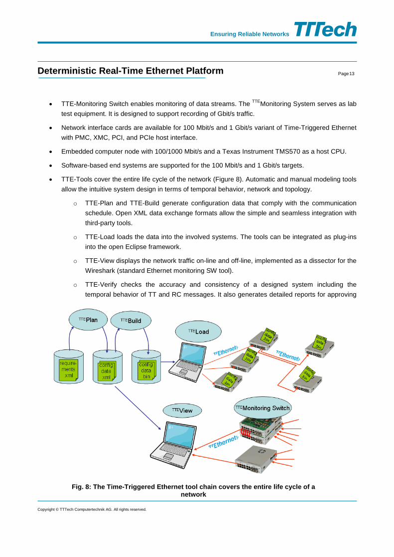
• TTE-Tools cover the entire life cycle of the network (Figure 8). Automatic and manual modeling tools allow the intuitive system design in terms of temporal behavior, network and topology.
o TTE-Plan and TTE-Build generate configuration data that comply with the communication schedule. Open XML data exchange formats allow the simple and seamless integration with third-party tools.
o TTE-Load loads the data into the involved systems. The tools can be integrated as plug-ins into the open Eclipse framework.
o TTE-View displays the network traffic on-line and off-line, implemented as a dissector for the Wireshark (standard Ethernet monitoring SW tool).
o TTE-Verify checks the accuracy and consistency of a designed system including the temporal behavior of TT and RC messages. It also generates detailed reports for approving
Fig. 8: The Time-Triggered Ethernet tool chain covers the entire life cycle of a network
Copyright © TTTech Computertechnik AG. All rights reserved.

14 Deterministic Real-Time Ethernet Platform Page
Ensuring Reliable Networks
a system in compliance with application regulations such as DO-178B in the aerospace industry (Figure 8).
• TTE-Evaluation Systems are available as 100 Mbit/s and 1 Gbit/s solutions, include a setup with multiple nodes and switches, Time-Triggered Ethernet -tools, as well as a demo application. They allow the investigation of Time-Triggered Ethernet features and rapid development of distributed real-time applications.
Standardization Activities Major Time-Triggered Ethernet services are defined in the SAE AS6802 standard. Standardization at the SAE International (Society of Automotive Engineers) was driven by the TTA-Group and completed in 2011. A further step was taken toward making Time-Triggered Ethernet generally available. Currently, intensive work is under way in the field of IEEE standardization to guarantee a compatibility of Time-Triggered Ethernet with the IEEE 802.1 family of standards and in particular with AVB. These activities are aimed at assuring current and future Time-Triggered Ethernet users that they can rely on a widely accepted standard.
Conclusion Time-Triggered Ethernet is a network topology that implements three different traffic classes that are suitable for different types of application, ranging from classical web services to time-critical and safety-critical control systems. It allows integration of different applications (with different criticality) within the same network and still guaranteeing the timely properties for the critical traffic. Integration of different application in the same network enables using a reduced number of networking components and enables saving potentials that secure major advantages in competitive markets. Typical areas of application for Time-Triggered Ethernet are highly-available systems for which failure is very costly. With Time-Triggered Ethernet, such systems can operate even in the presence faults, and repairs can be postponed to regular, but extended maintenance intervals.
Contact Astrit Ademaj, Product Manager TTTech Computertechnik AG Schoenbrunner Strasse 7 1040 Vienna, Austria Tel.: +43 1 585 34 34-986 Fax: +43 1 585 34 34-90 E-mail: [email protected] Web: www.tttech.com
Copyright © TTTech Computertechnik AG. All rights reserved.