time-to-digital-converter - acam · due to wrong component values or incorrect configuration of the...
TRANSCRIPT
Application Note
Time-to-Digital-Converter
Ultrasonic Heat metering with the
TDC-GP21 Time-to-Digital Converter
19th October 2011Document-No.: AN029_en V1.1
acam-messelectronic gmbh - Am Hasenbiel 27 - D-76297 Stutensee-Blankenloch - Germany - www.acam.de
Time-to-Digital-Converter
2
TDC-GP2
Overview
In December 2010 acam launched the TDC-GP21 Time-to-Digital Converter. It comes
with extended functionality and provides great benefit to designers that demand for ps
resolution in time of flight applications, e. g. like ultrasonic flow- and heat meters.
Especially, the integration of analog elements like a chopper stabilized comparator and
analog switches simplifies the hardware design and reduces the number of external com-
ponents to a minimum.
This application note is intended as an add on to the TDC-GP21 datasheet that describes
the implementation of an ultrasonic heat meter front-end with the TDC-GP21. It provi-
des additional information that helps to decrease design time and avoid circuit problems
due to wrong component values or incorrect configuration of the device. Additionally it
includes layout guidelines and the full schematics of a demo board to help avoid circuit
malfunction and to avoid noise problems. Finally, the application note contains a generic
software example that shows atypical measurement flow.
Note that the information provided herein is believed to be accurate and reliable. How-
ever, no responsibility is assumed by acam for its use, nor for any infringements of
patents or other rights of third parties that may result from its use. The information
is subject to change without notice and is provided „as is“ without warranty of any kind
(expressed or implied).
Author: Klaus Weser
acam-messelectronic gmbh - Am Hasenbiel 27 - D-76297 Stutensee-Blankenloch - Germany - www.acam.de 3
Table of Contents
TDC-GP2
1 Introduction ..................................................... 4
1.1 Flow Measurement ................................................................................5
1.2 Temperature Difference Measurement .....................................................7
2 Circuit Description ............................................ 8
2.1 Power Supply Considerations ..................................................................8
2.2 External Clock Sources ..........................................................................9
2.2.1 The 32,768 Hz Quartz ..................................................................9
2.2.2 The 4 MHz High Speed Clock Oscillator ............................................9
2.2.3 Clock Option for external Microcontroller .......................................10
2.3 Transmitter / Receiver Circuit ..............................................................10
2.3.1 Time Windowing by Stop Masking ..................................................12
3 Layout & Schematics of a demo board .............. 14
3.1 Full Schematics ...................................................................................14
3.2 Layout ................................................................................................15
3.2.1 Top Layer ....................................................................................15
3.2.2 Bottom Layer ..............................................................................16
3.2.3 Component Placement ..................................................................16
4 Example configuration ..................................... 17
5 Software Implementation ............................... 19
6 Example Code ................................................. 23
7 Literature References ..................................... 34
8 Revision History ............................................. 34
acam-messelectronic gmbh - Am Hasenbiel 27 - D-76297 Stutensee-Blankenloch - Germany - www.acam.de4
TDC-GP21TDC
acam-messelectronic gmbh - Am Hasenbiel 27 - D-76297 Stutensee-Blankenloch - Germany - www.acam.de4
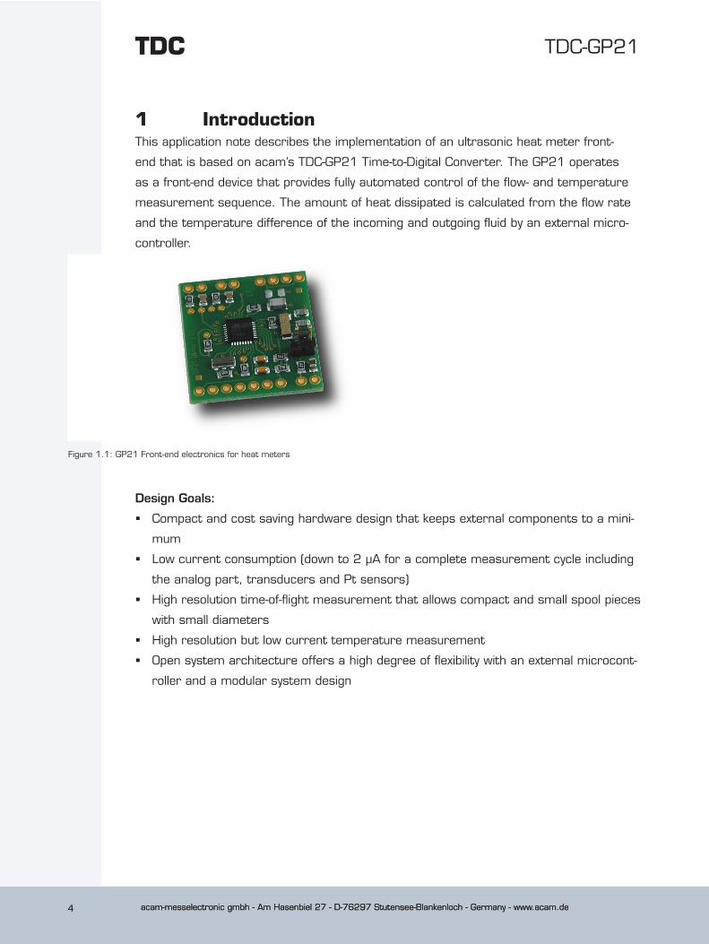
1 IntroductionThis application note describes the implementation of an ultrasonic heat meter front-
end that is based on acam’s TDC-GP21 Time-to-Digital Converter. The GP21 operates
as a front-end device that provides fully automated control of the flow- and temperature
measurement sequence. The amount of heat dissipated is calculated from the flow rate
and the temperature difference of the incoming and outgoing fluid by an external micro-
controller.
Figure 1.1: GP21 Front-end electronics for heat meters
Design Goals:
� Compact and cost saving hardware design that keeps external components to a mini-
mum
� Low current consumption (down to 2 µA for a complete measurement cycle including
the analog part, transducers and Pt sensors)
� High resolution time-of-flight measurement that allows compact and small spool pieces
with small diameters
� High resolution but low current temperature measurement
� Open system architecture offers a high degree of flexibility with an external microcont-
roller and a modular system design
acam-messelectronic gmbh - Am Hasenbiel 27 - D-76297 Stutensee-Blankenloch - Germany - www.acam.de 5
TDC-GP21
acam-messelectronic gmbh - Am Hasenbiel 27 - D-76297 Stutensee-Blankenloch - Germany - www.acam.de 5
Figure 1.1: GP21 Front-end electronics for heat meters
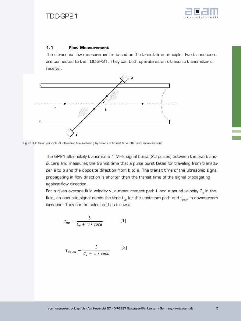
1.1 Flow Measurement
The ultrasonic flow measurement is based on the transit-time principle. Two transducers
are connected to the TDC-GP21. They can both operate as an ultrasonic transmitter or
receiver.
Figure 1.2 Basic principle of ultrasonic flow metering by means of transit time difference measurement
The GP21 alternately transmits a 1 MHz signal burst (20 pulses) between the two trans-
ducers and measures the transit time that a pulse burst takes for traveling from transdu-
cer a to b and the opposite direction from b to a. The transit time of the ultrasonic signal
propagating in flow direction is shorter than the transit time of the signal propagating
against flow direction.
For a given average fluid velocity v, a measurement path L and a sound velocity C0 in the
fluid, an acoustic signal needs the time tup for the upstream path and tdown in downstream
direction. They can be calculated as follows:
[1]
[2]
acam-messelectronic gmbh - Am Hasenbiel 27 - D-76297 Stutensee-Blankenloch - Germany - www.acam.de6
TDC-GP21TDC
acam-messelectronic gmbh - Am Hasenbiel 27 - D-76297 Stutensee-Blankenloch - Germany - www.acam.de6
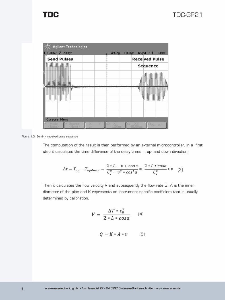
Figure 1.3: Send- / received pulse sequence
The computation of the result is then performed by an external microcontroller. In a first
step it calculates the time difference of the delay times in up- and down direction.
[3]
Then it calculates the flow velocity V and subsequently the flow rate Q. A is the inner
diameter of the pipe and K represents an instrument specific coefficient that is usually
determined by calibration.
[4]
[5]
Send Pulses Received Pulse
Sequence
acam-messelectronic gmbh - Am Hasenbiel 27 - D-76297 Stutensee-Blankenloch - Germany - www.acam.de 7
TDC-GP21
acam-messelectronic gmbh - Am Hasenbiel 27 - D-76297 Stutensee-Blankenloch - Germany - www.acam.de 7
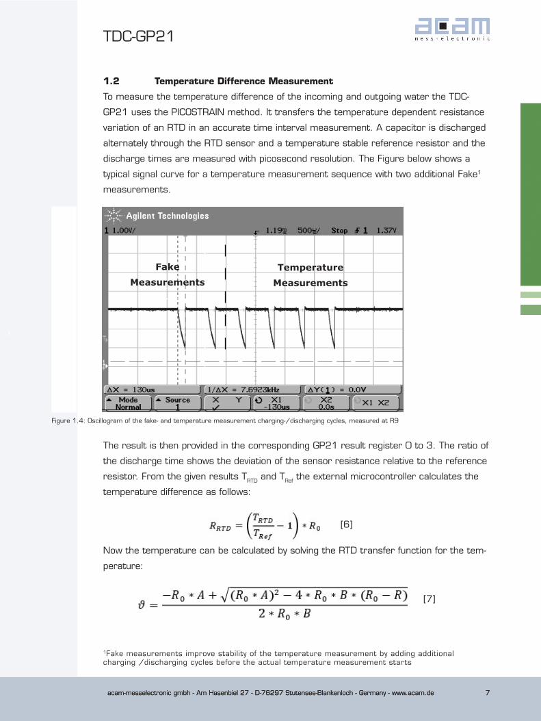
1.2 Temperature Difference Measurement
To measure the temperature difference of the incoming and outgoing water the TDC-
GP21 uses the PICOSTRAIN method. It transfers the temperature dependent resistance
variation of an RTD in an accurate time interval measurement. A capacitor is discharged
alternately through the RTD sensor and a temperature stable reference resistor and the
discharge times are measured with picosecond resolution. The Figure below shows a
typical signal curve for a temperature measurement sequence with two additional Fake1
measurements.
Figure 1.4: Oscillogram of the fake- and temperature measurement charging-/discharging cycles, measured at R9
The result is then provided in the corresponding GP21 result register 0 to 3. The ratio of
the discharge time shows the deviation of the sensor resistance relative to the reference
resistor. From the given results TRTD and TRef the external microcontroller calculates the
temperature difference as follows:
[6]
Now the temperature can be calculated by solving the RTD transfer function for the tem-
perature:
[7]
FakeMeasurements
TemperatureMeasurements
1Fake measurements improve stability of the temperature measurement by adding additional charging /discharging cycles before the actual temperature measurement starts
acam-messelectronic gmbh - Am Hasenbiel 27 - D-76297 Stutensee-Blankenloch - Germany - www.acam.de8
TDC-GP21TDC
acam-messelectronic gmbh - Am Hasenbiel 27 - D-76297 Stutensee-Blankenloch - Germany - www.acam.de8
Finally, the temperature difference is calculated as follows:
[8]
2 Circuit DescriptionThe complete schematics and the layout can be found in section 3 of this document. To
get best results and to avoid circuit problems we recommend to use it as a reference
for your design. The main considerable design items are now described in the following
chapters.
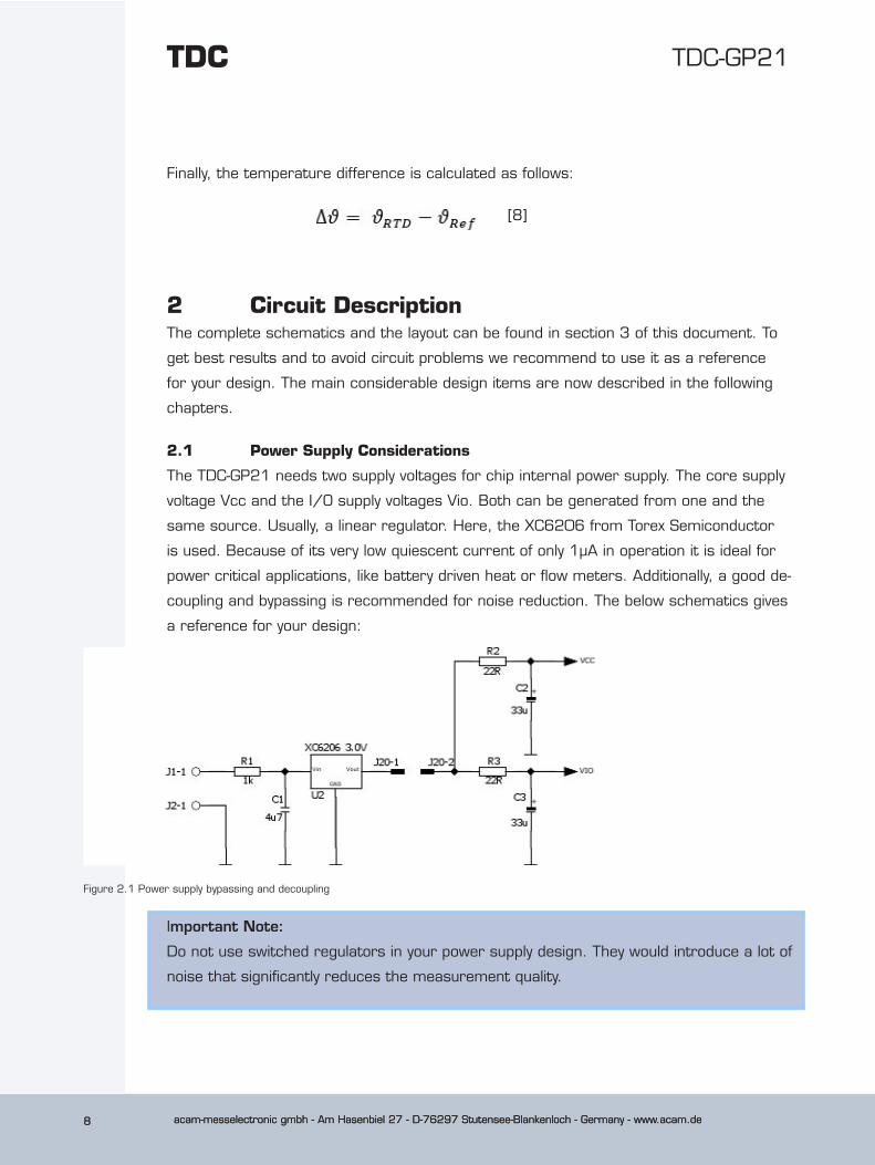
2.1 Power Supply Considerations
The TDC-GP21 needs two supply voltages for chip internal power supply. The core supply
voltage Vcc and the I/O supply voltages Vio. Both can be generated from one and the
same source. Usually, a linear regulator. Here, the XC6206 from Torex Semiconductor
is used. Because of its very low quiescent current of only 1µA in operation it is ideal for
power critical applications, like battery driven heat or flow meters. Additionally, a good de-
coupling and bypassing is recommended for noise reduction. The below schematics gives
a reference for your design:
Figure 2.1 Power supply bypassing and decoupling
Important Note:
Do not use switched regulators in your power supply design. They would introduce a lot of
noise that significantly reduces the measurement quality.
acam-messelectronic gmbh - Am Hasenbiel 27 - D-76297 Stutensee-Blankenloch - Germany - www.acam.de 9
TDC-GP21
acam-messelectronic gmbh - Am Hasenbiel 27 - D-76297 Stutensee-Blankenloch - Germany - www.acam.de 9
2.2 External Clock Sources
Battery driven applications like heat meters demand for very low current consumpti-
on. According to that the GP21 operates with two LVCMOS or LVTTL compatible clock
sources. A 32.768 kHz quartz and a 4 MHz ceramic oscillator. For power efficiency the
4 MHz clock is controlled by the 32 kHz quartz and only switched on during time measu-
rement.
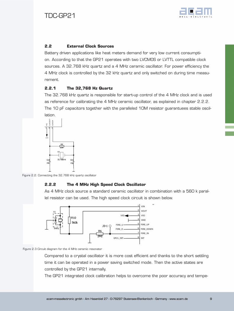
2.2.1 The 32,768 Hz Quartz
The 32.768 kHz quartz is responsible for start-up control of the 4 MHz clock and is used
as reference for calibrating the 4 MHz ceramic oscillator, as explained in chapter 2.2.2.
The 10 pF capacitors together with the paralleled 10M resistor guarantuees stable oscil-
lation.
Figure 2.2: Connecting the 32.768 kHz quartz oscillator
Figure 2.3 Circuit diagram for the 4 MHz ceramic resonator
Compared to a crystal oscillator it is more cost efficient and thanks to the short settling
time it can be operated in a power saving switched mode. Then the active states are
controlled by the GP21 internally.
The GP21 integrated clock calibration helps to overcome the poor accuracy and tempe-
2.2.2 The 4 MHz High Speed Clock Oscillator
As 4 MHz clock source a standard ceramic oscillator in combination with a 560 k paral-
lel resistor can be used. The high speed clock circuit is shown below.
acam-messelectronic gmbh - Am Hasenbiel 27 - D-76297 Stutensee-Blankenloch - Germany - www.acam.de10
TDC-GP21TDC
acam-messelectronic gmbh - Am Hasenbiel 27 - D-76297 Stutensee-Blankenloch - Germany - www.acam.de10
rature drift behavior that is typical for a ceramic oscillator. This offers quartz accurate
time measurement, even when a ceramic oscillator is used as high speed clock. For
more details about how to use the clock calibration please have a look to section 5.2 of
the TDC-GP21 datasheet.
2.2.3 Clock Option for external Microcontroller
To save external components the GP21 can provide a 4 kHz or a 32 kHz signal, e. g.
as a system clock for the external microcontroller. The 32 kHz can be provided through
EN_START pin and has to be configured by SEL_TST02 parameter in configuration regis-
ter 1. A 4 kHz signal is available on FIRE_IN by appropriate configuration of the
SEL_TST01 parameter in configuration register 1.
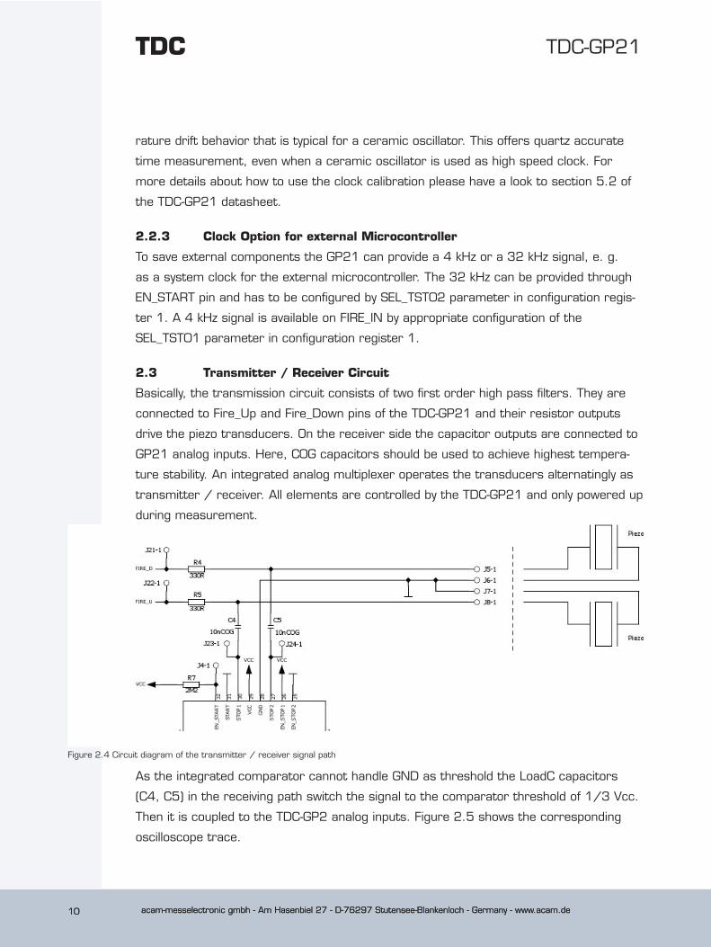
2.3 Transmitter / Receiver Circuit
Basically, the transmission circuit consists of two first order high pass filters. They are
connected to Fire_Up and Fire_Down pins of the TDC-GP21 and their resistor outputs
drive the piezo transducers. On the receiver side the capacitor outputs are connected to
GP21 analog inputs. Here, C0G capacitors should be used to achieve highest tempera-
ture stability. An integrated analog multiplexer operates the transducers alternatingly as
transmitter / receiver. All elements are controlled by the TDC-GP21 and only powered up
during measurement.
Figure 2.4 Circuit diagram of the transmitter / receiver signal path
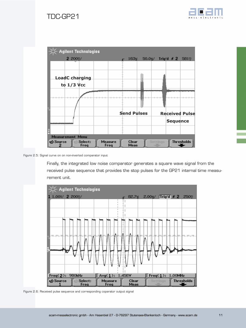
As the integrated comparator cannot handle GND as threshold the LoadC capacitors
(C4, C5) in the receiving path switch the signal to the comparator threshold of 1/3 Vcc.
Then it is coupled to the TDC-GP2 analog inputs. Figure 2.5 shows the corresponding
oscilloscope trace.
acam-messelectronic gmbh - Am Hasenbiel 27 - D-76297 Stutensee-Blankenloch - Germany - www.acam.de 11
TDC-GP21
acam-messelectronic gmbh - Am Hasenbiel 27 - D-76297 Stutensee-Blankenloch - Germany - www.acam.de 11
Figure 2.5: Signal curve on on non-inverted comparator input
Finally, the integrated low noise comparator generates a square wave signal from the
received pulse sequence that provides the stop pulses for the GP21 internal time measu-
rement unit.
Figure 2.6: Received pulse sequence and corresponding coparator output signal
LoadC charging to 1/3 Vcc
Send Pulses Received Pulse
Sequence
acam-messelectronic gmbh - Am Hasenbiel 27 - D-76297 Stutensee-Blankenloch - Germany - www.acam.de12
TDC-GP21TDC
acam-messelectronic gmbh - Am Hasenbiel 27 - D-76297 Stutensee-Blankenloch - Germany - www.acam.de12
More details about the GP21 analog unit and how it operates can be found in section 4.3
of the TDC-GP21 datasheet.
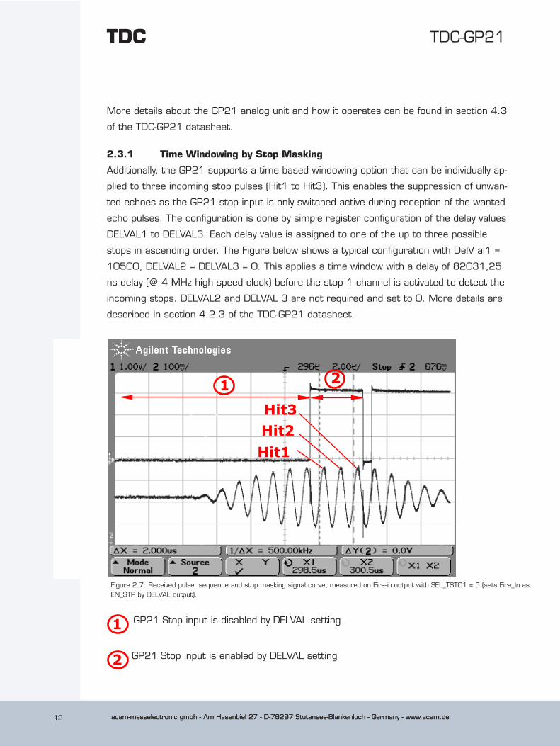
2.3.1 Time Windowing by Stop Masking
Additionally, the GP21 supports a time based windowing option that can be individually ap-
plied to three incoming stop pulses (Hit1 to Hit3). This enables the suppression of unwan-
ted echoes as the GP21 stop input is only switched active during reception of the wanted
echo pulses. The configuration is done by simple register configuration of the delay values
DELVAL1 to DELVAL3. Each delay value is assigned to one of the up to three possible
stops in ascending order. The Figure below shows a typical configuration with DelV al1 =
10500, DELVAL2 = DELVAL3 = 0. This applies a time window with a delay of 82031,25
ns delay (@ 4 MHz high speed clock) before the stop 1 channel is activated to detect the
incoming stops. DELVAL2 and DELVAL 3 are not required and set to 0. More details are
described in section 4.2.3 of the TDC-GP21 datasheet.
Figure 2.7: Received pulse sequence and stop masking signal curve, measured on Fire-in output with SEL_TST01 = 5 (sets Fire_In as EN_STP by DELVAL output).
Hit1Hit2Hit3
1 2
2
GP21 Stop input is disabled by DELVAL setting
GP21 Stop input is enabled by DELVAL setting
1
acam-messelectronic gmbh - Am Hasenbiel 27 - D-76297 Stutensee-Blankenloch - Germany - www.acam.de 13
TDC-GP21
acam-messelectronic gmbh - Am Hasenbiel 27 - D-76297 Stutensee-Blankenloch - Germany - www.acam.de 13
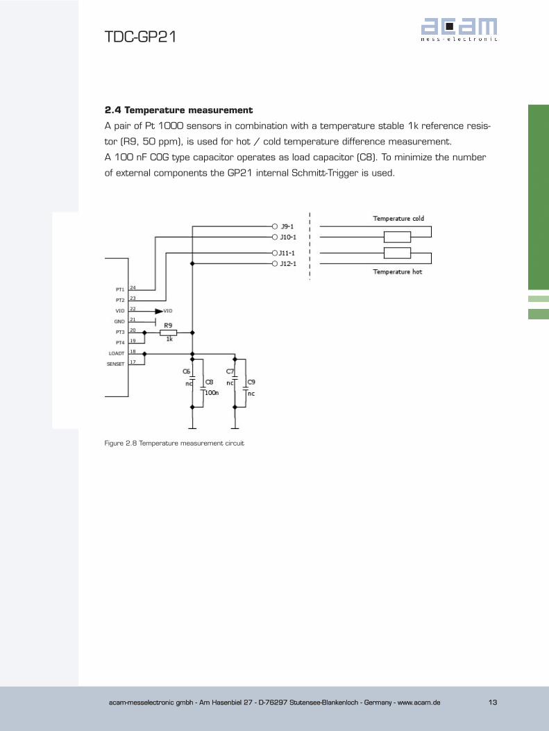
2.4 Temperature measurement
A pair of Pt 1000 sensors in combination with a temperature stable 1k reference resis-
tor (R9, 50 ppm), is used for hot / cold temperature difference measurement.
A 100 nF COG type capacitor operates as load capacitor (C8). To minimize the number
of external components the GP21 internal Schmitt-Trigger is used.
Figure 2.8 Temperature measurement circuit
acam-messelectronic gmbh - Am Hasenbiel 27 - D-76297 Stutensee-Blankenloch - Germany - www.acam.de14
TDC-GP21TDC
acam-messelectronic gmbh - Am Hasenbiel 27 - D-76297 Stutensee-Blankenloch - Germany - www.acam.de14
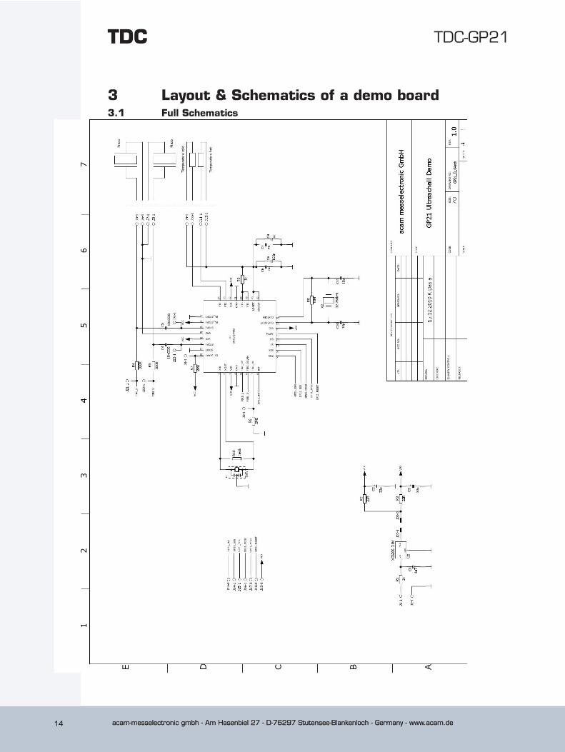
3 Layout & Schematics of a demo board3.1 Full Schematics
acam-messelectronic gmbh - Am Hasenbiel 27 - D-76297 Stutensee-Blankenloch - Germany - www.acam.de 15
TDC-GP21
acam-messelectronic gmbh - Am Hasenbiel 27 - D-76297 Stutensee-Blankenloch - Germany - www.acam.de 15
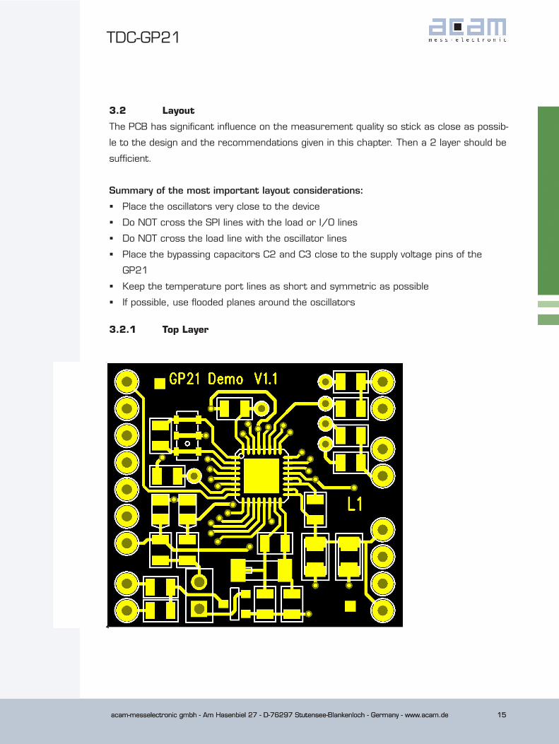
3.2 Layout
The PCB has significant influence on the measurement quality so stick as close as possib-
le to the design and the recommendations given in this chapter. Then a 2 layer should be
sufficient.
Summary of the most important layout considerations:
� Place the oscillators very close to the device
� Do NOT cross the SPI lines with the load or I/O lines
� Do NOT cross the load line with the oscillator lines
� Place the bypassing capacitors C2 and C3 close to the supply voltage pins of the
GP21
� Keep the temperature port lines as short and symmetric as possible
� If possible, use flooded planes around the oscillators
3.2.1 Top Layer
acam-messelectronic gmbh - Am Hasenbiel 27 - D-76297 Stutensee-Blankenloch - Germany - www.acam.de16
TDC-GP21TDC
acam-messelectronic gmbh - Am Hasenbiel 27 - D-76297 Stutensee-Blankenloch - Germany - www.acam.de16
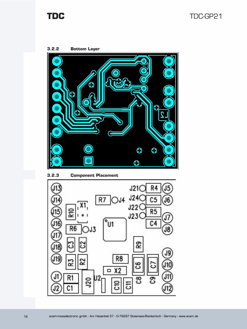
3.2.2 Bottom Layer
3.2.3 Component Placement
acam-messelectronic gmbh - Am Hasenbiel 27 - D-76297 Stutensee-Blankenloch - Germany - www.acam.de 17
TDC-GP21
acam-messelectronic gmbh - Am Hasenbiel 27 - D-76297 Stutensee-Blankenloch - Germany - www.acam.de 17
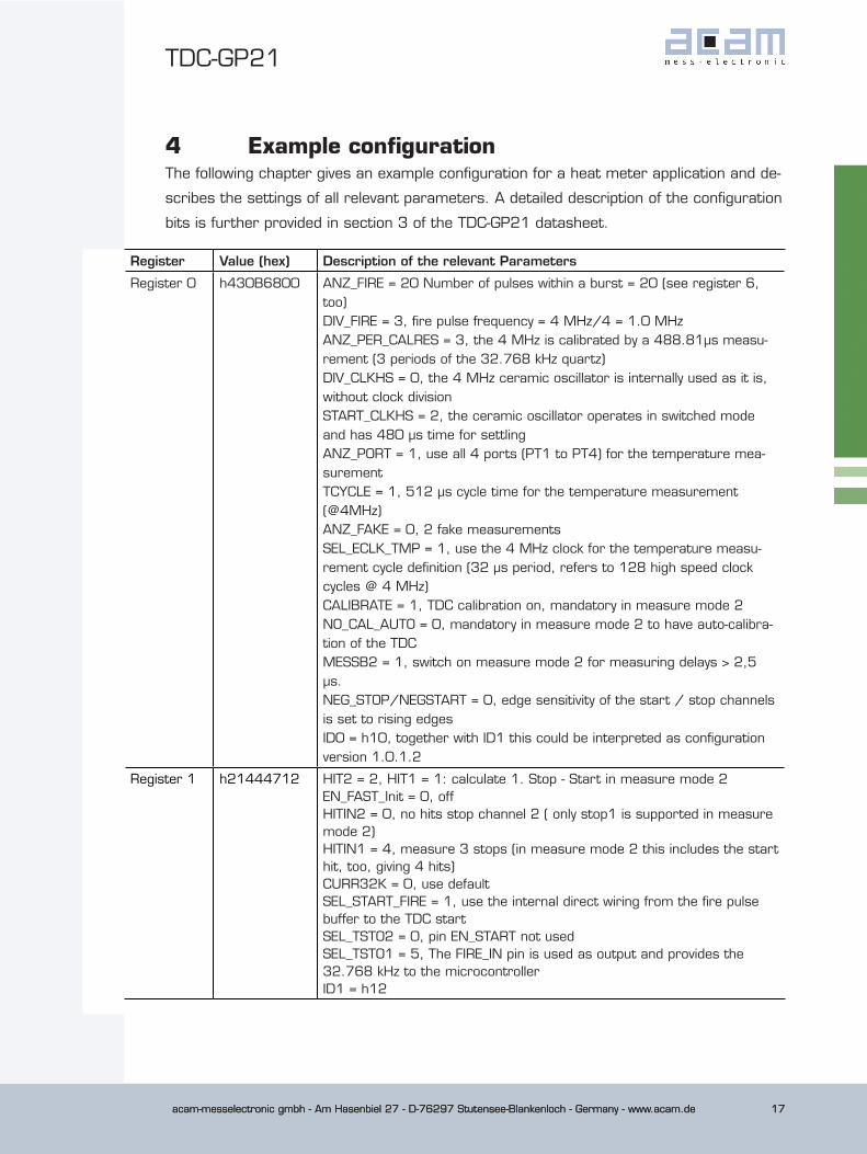
4 Example configurationThe following chapter gives an example configuration for a heat meter application and de-
scribes the settings of all relevant parameters. A detailed description of the configuration
bits is further provided in section 3 of the TDC-GP21 datasheet.
Register Value (hex) Description of the relevant Parameters
Register 0 h430B6800 ANZ_FIRE = 20 Number of pulses within a burst = 20 (see register 6, too)DIV_FIRE = 3, fire pulse frequency = 4 MHz/4 = 1.0 MHzANZ_PER_CALRES = 3, the 4 MHz is calibrated by a 488.81µs measu-rement (3 periods of the 32.768 kHz quartz)DIV_CLKHS = 0, the 4 MHz ceramic oscillator is internally used as it is, without clock divisionSTART_CLKHS = 2, the ceramic oscillator operates in switched mode and has 480 µs time for settlingANZ_PORT = 1, use all 4 ports (PT1 to PT4) for the temperature mea-surementTCYCLE = 1, 512 µs cycle time for the temperature measurement (@4MHz)ANZ_FAKE = 0, 2 fake measurementsSEL_ECLK_TMP = 1, use the 4 MHz clock for the temperature measu-rement cycle definition (32 µs period, refers to 128 high speed clock cycles @ 4 MHz) CALIBRATE = 1, TDC calibration on, mandatory in measure mode 2NO_CAL_AUTO = 0, mandatory in measure mode 2 to have auto-calibra-tion of the TDCMESSB2 = 1, switch on measure mode 2 for measuring delays > 2,5 µs.NEG_STOP/NEGSTART = 0, edge sensitivity of the start / stop channels is set to rising edgesID0 = h10, together with ID1 this could be interpreted as configuration version 1.0.1.2
Register 1 h21444712 HIT2 = 2, HIT1 = 1: calculate 1. Stop - Start in measure mode 2EN_FAST_Init = 0, off HITIN2 = 0, no hits stop channel 2 ( only stop1 is supported in measure mode 2)HITIN1 = 4, measure 3 stops (in measure mode 2 this includes the start hit, too, giving 4 hits)CURR32K = 0, use defaultSEL_START_FIRE = 1, use the internal direct wiring from the fire pulse buffer to the TDC startSEL_TSTO2 = 0, pin EN_START not usedSEL_TSTO1 = 5, The FIRE_IN pin is used as output and provides the 32.768 kHz to the microcontrollerID1 = h12

acam-messelectronic gmbh - Am Hasenbiel 27 - D-76297 Stutensee-Blankenloch - Germany - www.acam.de18
TDC-GP21TDC
acam-messelectronic gmbh - Am Hasenbiel 27 - D-76297 Stutensee-Blankenloch - Germany - www.acam.de18
Register 2 hE0290412 EN_INT = all interrupts enabled (interrupt given by timeout, ALU ready end hits or end of EEPROM action (see also register 6)RFEDGE1 = RFEDGE2 = 0, use only rising edgesDELVAL1 = 328,125, the first stop is accepted after 82.0375 µsID2 = h12, could be part of a serial number h1234567890
Register 3 h08000034 EN_ERR_VAL = 0, there is enough time to read the status registerSEL_TIMO_MB2 = 1, time out is generated after 256 µsDELVAL2 = 0, the second stop is detected immediately after the first one (no masking for the second stop))ID3 = h34, could be part of a serial number h1234567890
Register 4 H10000056 DELVAL3 = 0, the third stop is accepted immediately after the second one (no masking for the third stop)ID4 = h56, could be part of a serial number h1234567890
Register 5 H40000078 CON_FIRE = 2, disable FIRE_UP; Fire1 and Fire2 are used alternately. The flow measurement sequence starts in downstream directionEN_STARTNOISE = 0, switch offDIS_PHASESHIFT = 0, phase noise unit is active to improve the statistical behaviorREPEAT_FIRE = 0, no sing-aroundPHASE_FIRE = 0, no phase change in the fire pulse sequenceID5 = h78, could be part of a serial number h1234567890
Register 6 hC0006190 EN_ANALOG = 1, use the internal analog circuitNEG_STOP_TEMP = 1, use the internal Schmitt trigger for the tempera-ture measurementTW2 = 1, 120 µs delay to charge up the capacitors of the high pass filtersEN_INT = b1101, interrupt given by time out, ALU ready or end of EE-PROM action (see also register 2)START_CLKHS = 2, the ceramic oscillator has 480 µs to settle (see also register 0)CYCLE_TEMP = 1, use factor 1.5 for the delay between two measure-mentsCYCLE_TOF = 0, use factor 1.0 for the delay between two TOF measure-mentsHZ60 = 0, 50 Hz baseFIREO_DEF = 1, High Z state of the unused fire output, mandatory when using the internal analog circuitQUAD_RES = 1, use 22 ps resolution of the TDCDOUBLE_RES = 0, mandatory as quad resolution mode is selectedTEMP_PORTDIR = 0, standard order for T measurementANZ_FIRE = 20 (see register 0, too)ID6 = h90, could be part of a serial number h1234567890
acam-messelectronic gmbh - Am Hasenbiel 27 - D-76297 Stutensee-Blankenloch - Germany - www.acam.de 19
TDC-GP21
acam-messelectronic gmbh - Am Hasenbiel 27 - D-76297 Stutensee-Blankenloch - Germany - www.acam.de 19
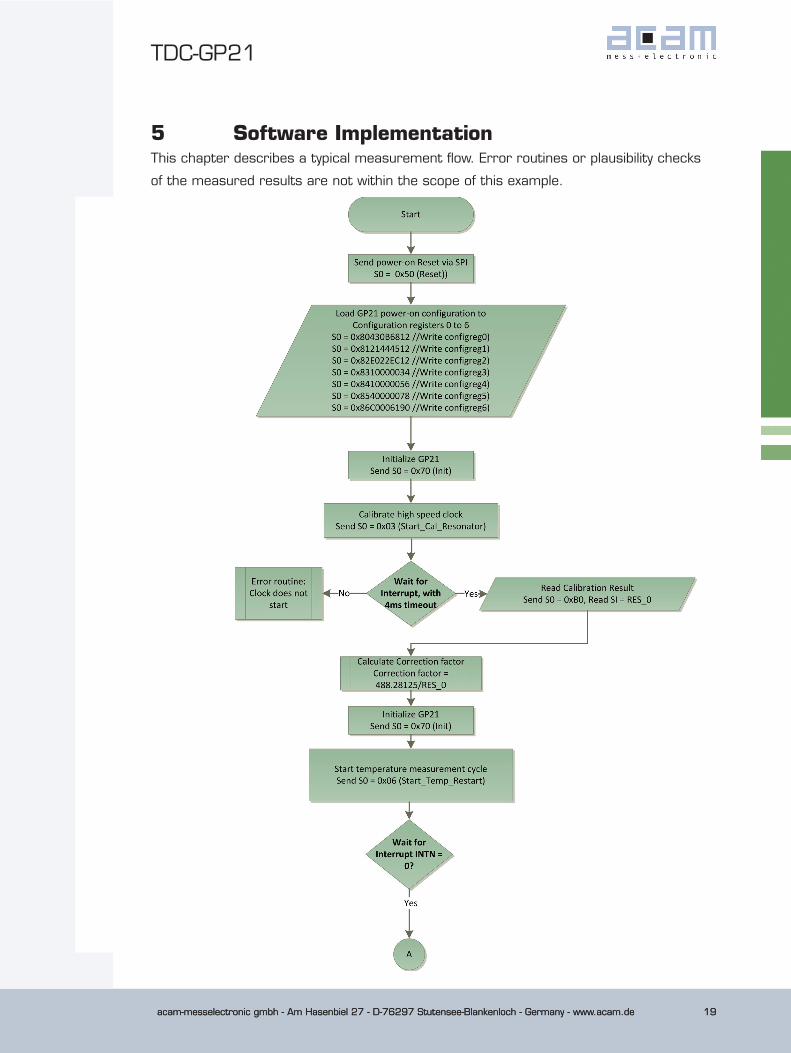
5 Software ImplementationThis chapter describes a typical measurement flow. Error routines or plausibility checks
of the measured results are not within the scope of this example.
acam-messelectronic gmbh - Am Hasenbiel 27 - D-76297 Stutensee-Blankenloch - Germany - www.acam.de20
TDC-GP21TDC
acam-messelectronic gmbh - Am Hasenbiel 27 - D-76297 Stutensee-Blankenloch - Germany - www.acam.de20
acam-messelectronic gmbh - Am Hasenbiel 27 - D-76297 Stutensee-Blankenloch - Germany - www.acam.de 21
TDC-GP21
acam-messelectronic gmbh - Am Hasenbiel 27 - D-76297 Stutensee-Blankenloch - Germany - www.acam.de 21
acam-messelectronic gmbh - Am Hasenbiel 27 - D-76297 Stutensee-Blankenloch - Germany - www.acam.de22
TDC-GP21TDC
acam-messelectronic gmbh - Am Hasenbiel 27 - D-76297 Stutensee-Blankenloch - Germany - www.acam.de22
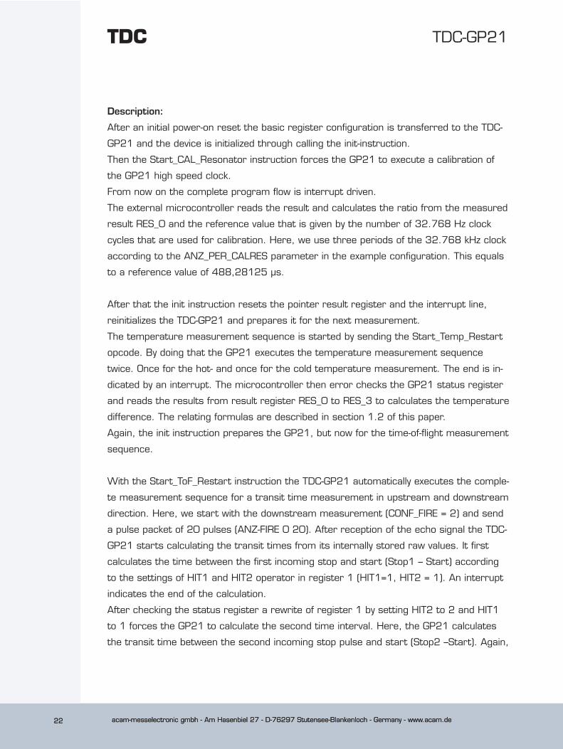
Description:
After an initial power-on reset the basic register configuration is transferred to the TDC-
GP21 and the device is initialized through calling the init-instruction.
Then the Start_CAL_Resonator instruction forces the GP21 to execute a calibration of
the GP21 high speed clock.
From now on the complete program flow is interrupt driven.
The external microcontroller reads the result and calculates the ratio from the measured
result RES_0 and the reference value that is given by the number of 32.768 Hz clock
cycles that are used for calibration. Here, we use three periods of the 32.768 kHz clock
according to the ANZ_PER_CALRES parameter in the example configuration. This equals
to a reference value of 488,28125 µs.
After that the init instruction resets the pointer result register and the interrupt line,
reinitializes the TDC-GP21 and prepares it for the next measurement.
The temperature measurement sequence is started by sending the Start_Temp_Restart
opcode. By doing that the GP21 executes the temperature measurement sequence
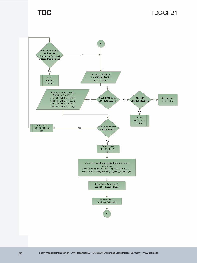
twice. Once for the hot- and once for the cold temperature measurement. The end is in-
dicated by an interrupt. The microcontroller then error checks the GP21 status register
and reads the results from result register RES_0 to RES_3 to calculates the temperature
difference. The relating formulas are described in section 1.2 of this paper.
Again, the init instruction prepares the GP21, but now for the time-of-flight measurement
sequence.
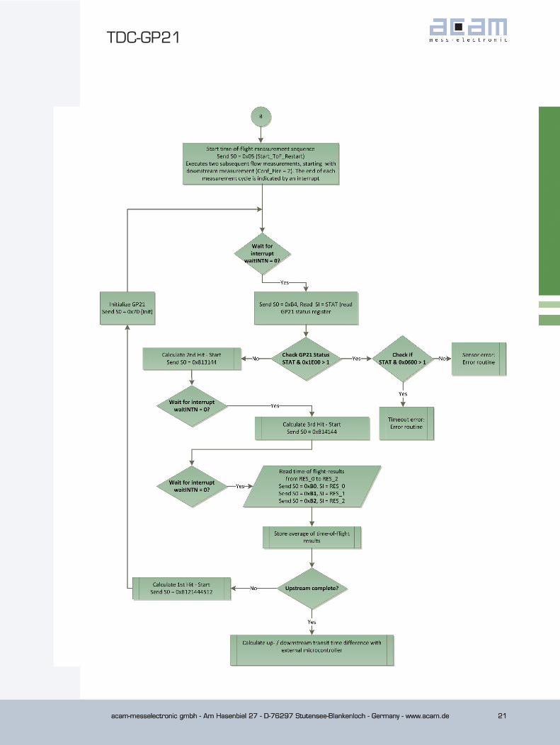
With the Start_ToF_Restart instruction the TDC-GP21 automatically executes the comple-
te measurement sequence for a transit time measurement in upstream and downstream
direction. Here, we start with the downstream measurement (CONF_FIRE = 2) and send
a pulse packet of 20 pulses (ANZ-FIRE 0 20). After reception of the echo signal the TDC-
GP21 starts calculating the transit times from its internally stored raw values. It first
calculates the time between the first incoming stop and start (Stop1 – Start) according
to the settings of HIT1 and HIT2 operator in register 1 (HIT1=1, HIT2 = 1). An interrupt
indicates the end of the calculation.
After checking the status register a rewrite of register 1 by setting HIT2 to 2 and HIT1
to 1 forces the GP21 to calculate the second time interval. Here, the GP21 calculates
the transit time between the second incoming stop pulse and start (Stop2 –Start). Again,
acam-messelectronic gmbh - Am Hasenbiel 27 - D-76297 Stutensee-Blankenloch - Germany - www.acam.de 23
TDC-GP21
acam-messelectronic gmbh - Am Hasenbiel 27 - D-76297 Stutensee-Blankenloch - Germany - www.acam.de 23
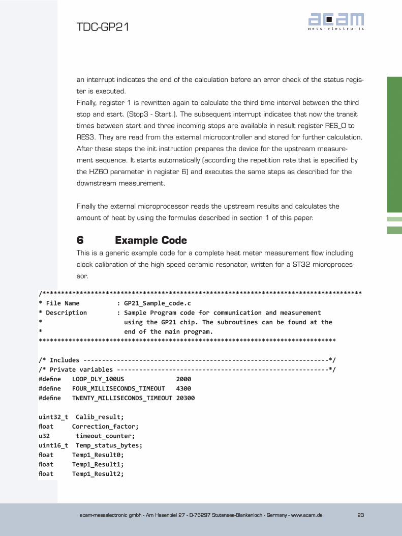
an interrupt indicates the end of the calculation before an error check of the status regis-
ter is executed.
Finally, register 1 is rewritten again to calculate the third time interval between the third
stop and start. (Stop3 - Start.). The subsequent interrupt indicates that now the transit
times between start and three incoming stops are available in result register RES_0 to
RES3. They are read from the external microcontroller and stored for further calculation.
After these steps the init instruction prepares the device for the upstream measure-
ment sequence. It starts automatically (according the repetition rate that is specified by
the HZ60 parameter in register 6) and executes the same steps as described for the
downstream measurement.
Finally the external microprocessor reads the upstream results and calculates the
amount of heat by using the formulas described in section 1 of this paper.
6 Example CodeThis is a generic example code for a complete heat meter measurement flow including
clock calibration of the high speed ceramic resonator, written for a ST32 microproces-
sor.
/*************************************************************************************** File Name : GP21_Sample_code.c* Description : Sample Program code for communication and measurement * using the GP21 chip. The subroutines can be found at the * end of the main program.********************************************************************************
/* Includes ------------------------------------------------------------------*//* Private variables ---------------------------------------------------------*/#define LOOP_DLY_100US 2000#define FOUR_MILLISECONDS_TIMEOUT 4300#define TWENTY_MILLISECONDS_TIMEOUT 20300
uint32_t Calib_result;float Correction_factor;u32 timeout_counter;uint16_t Temp_status_bytes;float Temp1_Result0;float Temp1_Result1;float Temp1_Result2;
acam-messelectronic gmbh - Am Hasenbiel 27 - D-76297 Stutensee-Blankenloch - Germany - www.acam.de24
TDC-GP21TDC
acam-messelectronic gmbh - Am Hasenbiel 27 - D-76297 Stutensee-Blankenloch - Germany - www.acam.de24
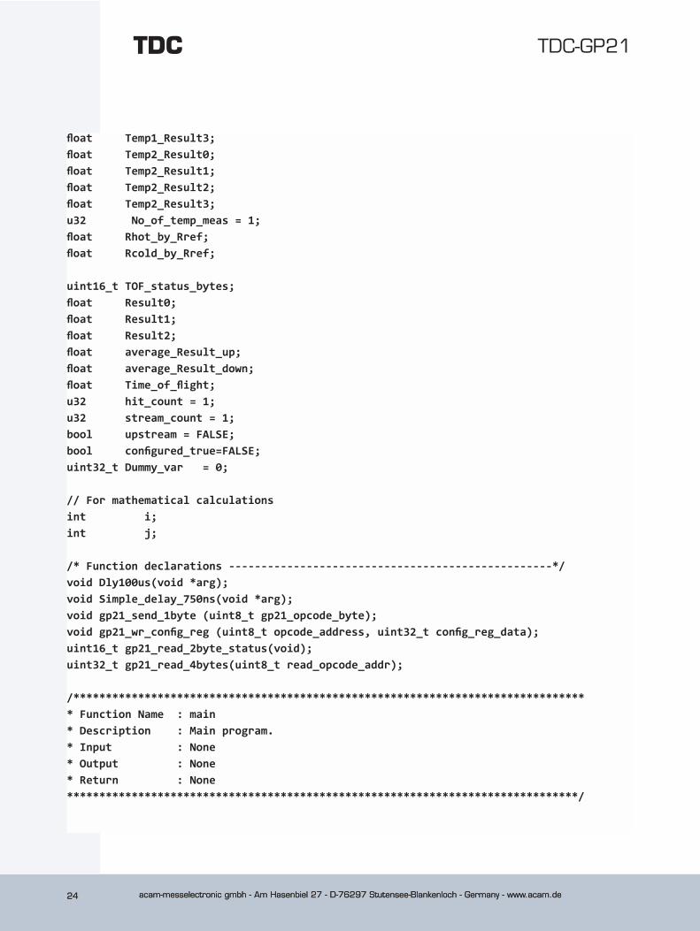
float Temp1_Result3;float Temp2_Result0;float Temp2_Result1;float Temp2_Result2;float Temp2_Result3;u32 No_of_temp_meas = 1;float Rhot_by_Rref;float Rcold_by_Rref;
uint16_t TOF_status_bytes;float Result0;float Result1;float Result2;float average_Result_up;float average_Result_down;float Time_of_flight;u32 hit_count = 1;u32 stream_count = 1;bool upstream = FALSE;bool configured_true=FALSE;uint32_t Dummy_var = 0;
// For mathematical calculationsint i;int j;
/* Function declarations --------------------------------------------------*/void Dly100us(void *arg);void Simple_delay_750ns(void *arg);void gp21_send_1byte (uint8_t gp21_opcode_byte);void gp21_wr_config_reg (uint8_t opcode_address, uint32_t config_reg_data);uint16_t gp21_read_2byte_status(void);uint32_t gp21_read_4bytes(uint8_t read_opcode_addr);
/******************************************************************************** Function Name : main* Description : Main program.* Input : None* Output : None* Return : None*******************************************************************************/
acam-messelectronic gmbh - Am Hasenbiel 27 - D-76297 Stutensee-Blankenloch - Germany - www.acam.de 25
TDC-GP21
acam-messelectronic gmbh - Am Hasenbiel 27 - D-76297 Stutensee-Blankenloch - Germany - www.acam.de 25
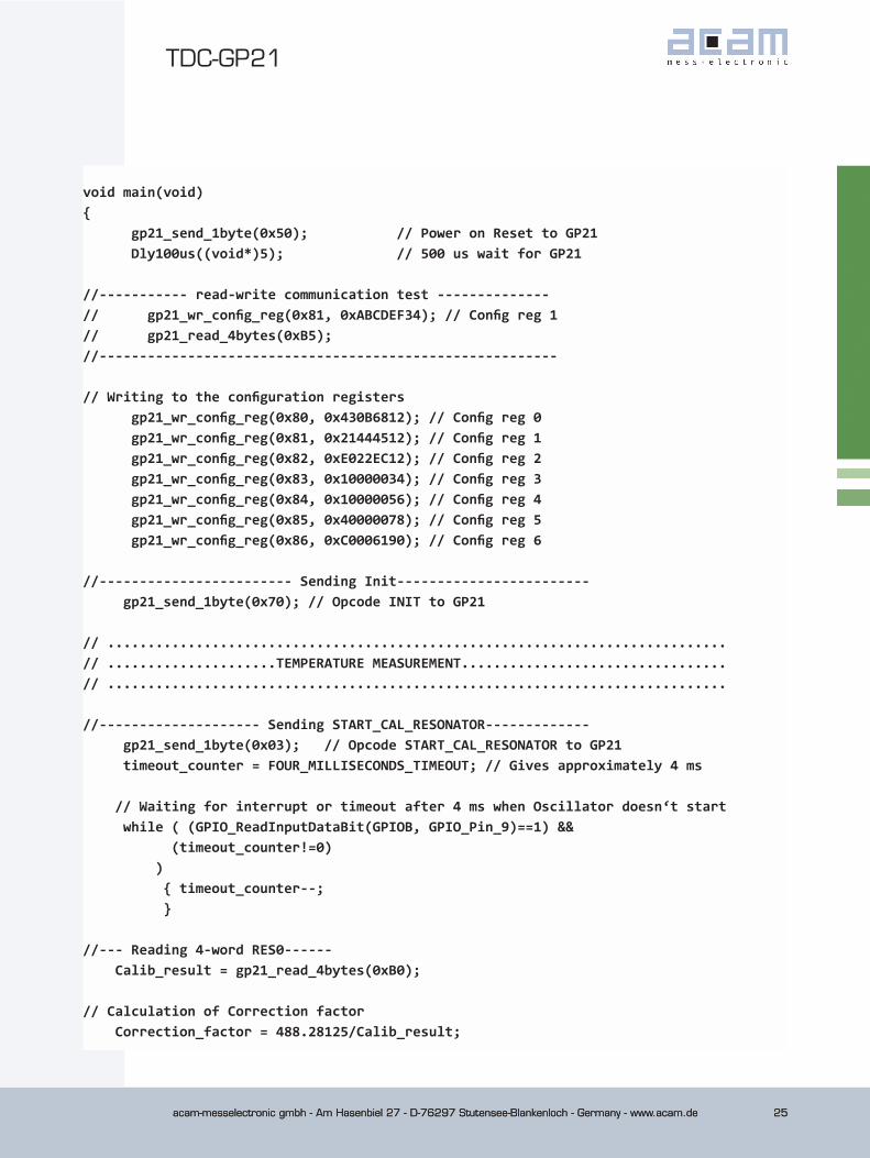
void main(void){ gp21_send_1byte(0x50); // Power on Reset to GP21 Dly100us((void*)5); // 500 us wait for GP21
//----------- read-write communication test --------------// gp21_wr_config_reg(0x81, 0xABCDEF34); // Config reg 1// gp21_read_4bytes(0xB5);//--------------------------------------------------------- // Writing to the configuration registers gp21_wr_config_reg(0x80, 0x430B6812); // Config reg 0 gp21_wr_config_reg(0x81, 0x21444512); // Config reg 1 gp21_wr_config_reg(0x82, 0xE022EC12); // Config reg 2 gp21_wr_config_reg(0x83, 0x10000034); // Config reg 3 gp21_wr_config_reg(0x84, 0x10000056); // Config reg 4 gp21_wr_config_reg(0x85, 0x40000078); // Config reg 5 gp21_wr_config_reg(0x86, 0xC0006190); // Config reg 6
//------------------------ Sending Init------------------------ gp21_send_1byte(0x70); // Opcode INIT to GP21
// .............................................................................// .....................TEMPERATURE MEASUREMENT.................................// .............................................................................
//-------------------- Sending START_CAL_RESONATOR------------- gp21_send_1byte(0x03); // Opcode START_CAL_RESONATOR to GP21 timeout_counter = FOUR_MILLISECONDS_TIMEOUT; // Gives approximately 4 ms // Waiting for interrupt or timeout after 4 ms when Oscillator doesn‘t start while ( (GPIO_ReadInputDataBit(GPIOB, GPIO_Pin_9)==1) && (timeout_counter!=0) ) { timeout_counter--; } //--- Reading 4-word RES0------ Calib_result = gp21_read_4bytes(0xB0); // Calculation of Correction factor Correction_factor = 488.28125/Calib_result;
acam-messelectronic gmbh - Am Hasenbiel 27 - D-76297 Stutensee-Blankenloch - Germany - www.acam.de26
TDC-GP21TDC
acam-messelectronic gmbh - Am Hasenbiel 27 - D-76297 Stutensee-Blankenloch - Germany - www.acam.de26
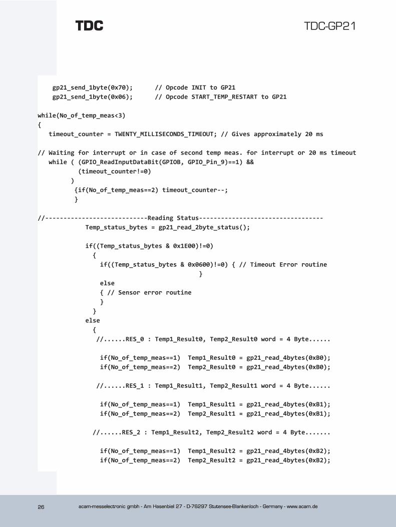
gp21_send_1byte(0x70); // Opcode INIT to GP21 gp21_send_1byte(0x06); // Opcode START_TEMP_RESTART to GP21 while(No_of_temp_meas<3) { timeout_counter = TWENTY_MILLISECONDS_TIMEOUT; // Gives approximately 20 ms // Waiting for interrupt or in case of second temp meas. for interrupt or 20 ms timeout while ( (GPIO_ReadInputDataBit(GPIOB, GPIO_Pin_9)==1) && (timeout_counter!=0) ) {if(No_of_temp_meas==2) timeout_counter--; } //----------------------------Reading Status---------------------------------- Temp_status_bytes = gp21_read_2byte_status(); if((Temp_status_bytes & 0x1E00)!=0) { if((Temp_status_bytes & 0x0600)!=0) { // Timeout Error routine } else { // Sensor error routine } } else { //......RES_0 : Temp1_Result0, Temp2_Result0 word = 4 Byte...... if(No_of_temp_meas==1) Temp1_Result0 = gp21_read_4bytes(0xB0); if(No_of_temp_meas==2) Temp2_Result0 = gp21_read_4bytes(0xB0); //......RES_1 : Temp1_Result1, Temp2_Result1 word = 4 Byte...... if(No_of_temp_meas==1) Temp1_Result1 = gp21_read_4bytes(0xB1); if(No_of_temp_meas==2) Temp2_Result1 = gp21_read_4bytes(0xB1); //......RES_2 : Temp1_Result2, Temp2_Result2 word = 4 Byte....... if(No_of_temp_meas==1) Temp1_Result2 = gp21_read_4bytes(0xB2); if(No_of_temp_meas==2) Temp2_Result2 = gp21_read_4bytes(0xB2);
acam-messelectronic gmbh - Am Hasenbiel 27 - D-76297 Stutensee-Blankenloch - Germany - www.acam.de 27
TDC-GP21
acam-messelectronic gmbh - Am Hasenbiel 27 - D-76297 Stutensee-Blankenloch - Germany - www.acam.de 27
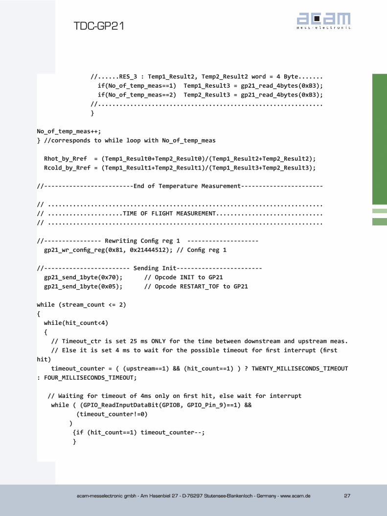
//......RES_3 : Temp1_Result2, Temp2_Result2 word = 4 Byte....... if(No_of_temp_meas==1) Temp1_Result3 = gp21_read_4bytes(0xB3); if(No_of_temp_meas==2) Temp2_Result3 = gp21_read_4bytes(0xB3); //............................................................... }
No_of_temp_meas++; } //corresponds to while loop with No_of_temp_meas
Rhot_by_Rref = (Temp1_Result0+Temp2_Result0)/(Temp1_Result2+Temp2_Result2); Rcold_by_Rref = (Temp1_Result1+Temp2_Result1)/(Temp1_Result3+Temp2_Result3); //-------------------------End of Temperature Measurement----------------------- // .............................................................................// .....................TIME OF FLIGHT MEASUREMENT..............................// ............................................................................. //---------------- Rewriting Config reg 1 -------------------- gp21_wr_config_reg(0x81, 0x21444512); // Config reg 1 //------------------------ Sending Init------------------------ gp21_send_1byte(0x70); // Opcode INIT to GP21 gp21_send_1byte(0x05); // Opcode RESTART_TOF to GP21
while (stream_count <= 2) { while(hit_count<4) { // Timeout_ctr is set 25 ms ONLY for the time between downstream and upstream meas. // Else it is set 4 ms to wait for the possible timeout for first interrupt (first hit) timeout_counter = ( (upstream==1) && (hit_count==1) ) ? TWENTY_MILLISECONDS_TIMEOUT : FOUR_MILLISECONDS_TIMEOUT; // Waiting for timeout of 4ms only on first hit, else wait for interrupt while ( (GPIO_ReadInputDataBit(GPIOB, GPIO_Pin_9)==1) && (timeout_counter!=0) ) {if (hit_count==1) timeout_counter--; }
acam-messelectronic gmbh - Am Hasenbiel 27 - D-76297 Stutensee-Blankenloch - Germany - www.acam.de28
TDC-GP21TDC
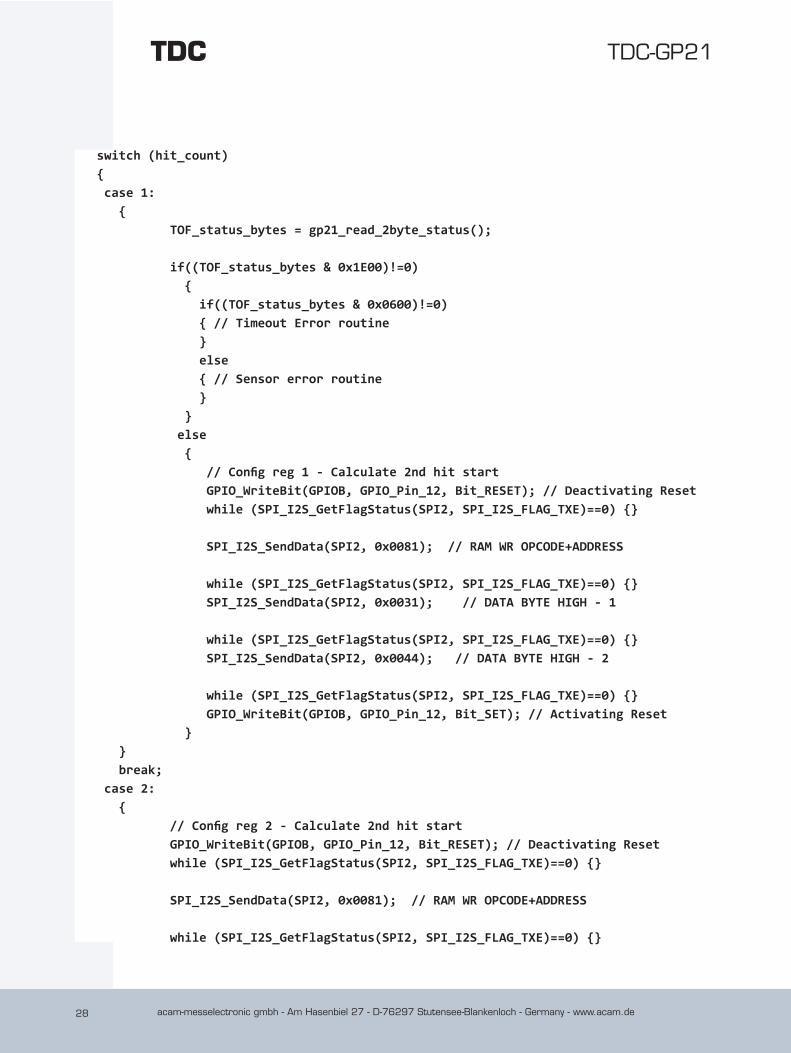
switch (hit_count) { case 1: { TOF_status_bytes = gp21_read_2byte_status(); if((TOF_status_bytes & 0x1E00)!=0) { if((TOF_status_bytes & 0x0600)!=0) { // Timeout Error routine } else { // Sensor error routine } } else { // Config reg 1 - Calculate 2nd hit start GPIO_WriteBit(GPIOB, GPIO_Pin_12, Bit_RESET); // Deactivating Reset while (SPI_I2S_GetFlagStatus(SPI2, SPI_I2S_FLAG_TXE)==0) {} SPI_I2S_SendData(SPI2, 0x0081); // RAM WR OPCODE+ADDRESS
while (SPI_I2S_GetFlagStatus(SPI2, SPI_I2S_FLAG_TXE)==0) {} SPI_I2S_SendData(SPI2, 0x0031); // DATA BYTE HIGH - 1 while (SPI_I2S_GetFlagStatus(SPI2, SPI_I2S_FLAG_TXE)==0) {} SPI_I2S_SendData(SPI2, 0x0044); // DATA BYTE HIGH - 2 while (SPI_I2S_GetFlagStatus(SPI2, SPI_I2S_FLAG_TXE)==0) {} GPIO_WriteBit(GPIOB, GPIO_Pin_12, Bit_SET); // Activating Reset } } break; case 2: { // Config reg 2 - Calculate 2nd hit start GPIO_WriteBit(GPIOB, GPIO_Pin_12, Bit_RESET); // Deactivating Reset while (SPI_I2S_GetFlagStatus(SPI2, SPI_I2S_FLAG_TXE)==0) {} SPI_I2S_SendData(SPI2, 0x0081); // RAM WR OPCODE+ADDRESS while (SPI_I2S_GetFlagStatus(SPI2, SPI_I2S_FLAG_TXE)==0) {}
acam-messelectronic gmbh - Am Hasenbiel 27 - D-76297 Stutensee-Blankenloch - Germany - www.acam.de 29
TDC-GP21
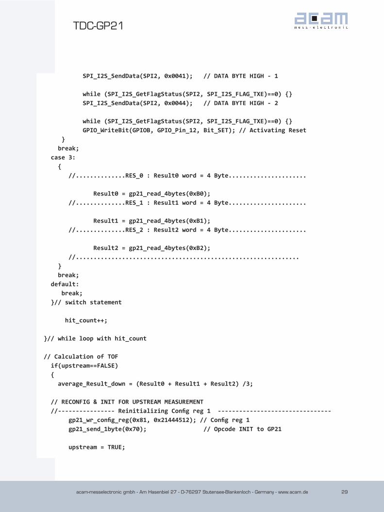
SPI_I2S_SendData(SPI2, 0x0041); // DATA BYTE HIGH - 1 while (SPI_I2S_GetFlagStatus(SPI2, SPI_I2S_FLAG_TXE)==0) {} SPI_I2S_SendData(SPI2, 0x0044); // DATA BYTE HIGH - 2 while (SPI_I2S_GetFlagStatus(SPI2, SPI_I2S_FLAG_TXE)==0) {} GPIO_WriteBit(GPIOB, GPIO_Pin_12, Bit_SET); // Activating Reset } break; case 3: { //..............RES_0 : Result0 word = 4 Byte......................
Result0 = gp21_read_4bytes(0xB0); //..............RES_1 : Result1 word = 4 Byte......................
Result1 = gp21_read_4bytes(0xB1); //..............RES_2 : Result2 word = 4 Byte......................
Result2 = gp21_read_4bytes(0xB2); //............................................................... } break; default: break; }// switch statement hit_count++; }// while loop with hit_count // Calculation of TOF if(upstream==FALSE) { average_Result_down = (Result0 + Result1 + Result2) /3; // RECONFIG & INIT FOR UPSTREAM MEASUREMENT //---------------- Reinitializing Config reg 1 -------------------------------- gp21_wr_config_reg(0x81, 0x21444512); // Config reg 1 gp21_send_1byte(0x70); // Opcode INIT to GP21
upstream = TRUE;
acam-messelectronic gmbh - Am Hasenbiel 27 - D-76297 Stutensee-Blankenloch - Germany - www.acam.de30
TDC-GP21TDC
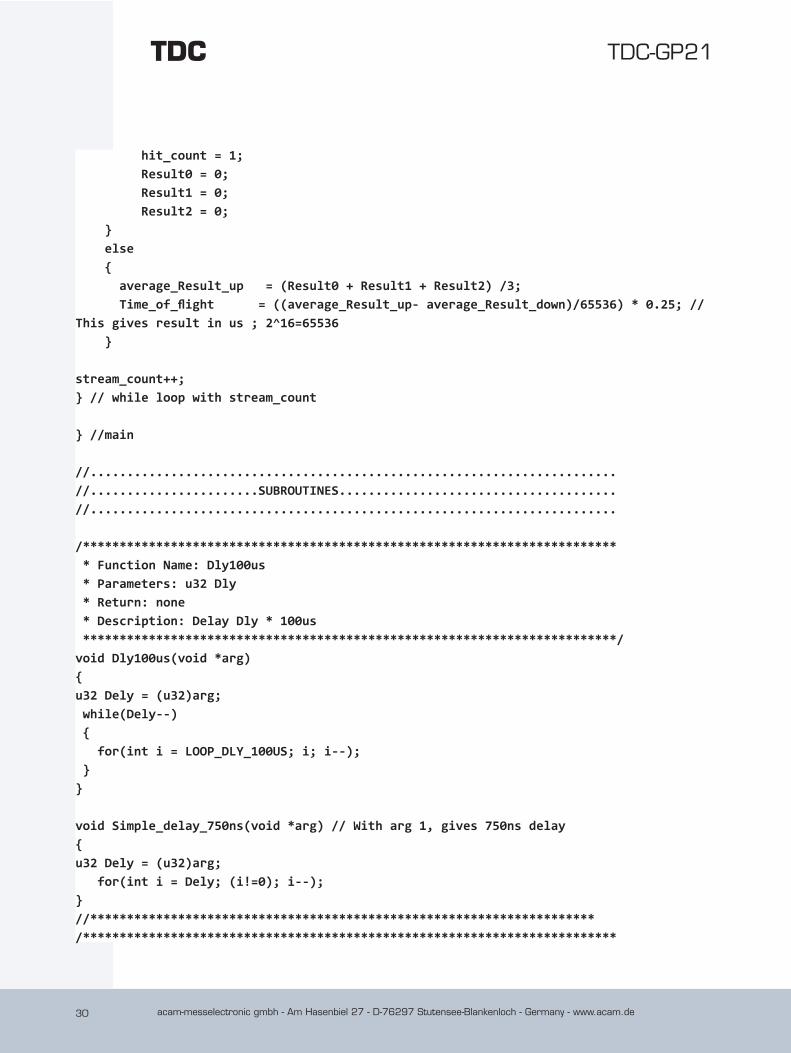
hit_count = 1; Result0 = 0; Result1 = 0; Result2 = 0; } else { average_Result_up = (Result0 + Result1 + Result2) /3; Time_of_flight = ((average_Result_up- average_Result_down)/65536) * 0.25; // This gives result in us ; 2^16=65536 }
stream_count++; } // while loop with stream_count
} //main
//........................................................................//.......................SUBROUTINES......................................//........................................................................
/************************************************************************* * Function Name: Dly100us * Parameters: u32 Dly * Return: none * Description: Delay Dly * 100us *************************************************************************/void Dly100us(void *arg){u32 Dely = (u32)arg; while(Dely--) { for(int i = LOOP_DLY_100US; i; i--); }}
void Simple_delay_750ns(void *arg) // With arg 1, gives 750ns delay{u32 Dely = (u32)arg; for(int i = Dely; (i!=0); i--);}//*********************************************************************/*************************************************************************
acam-messelectronic gmbh - Am Hasenbiel 27 - D-76297 Stutensee-Blankenloch - Germany - www.acam.de 31
TDC-GP21
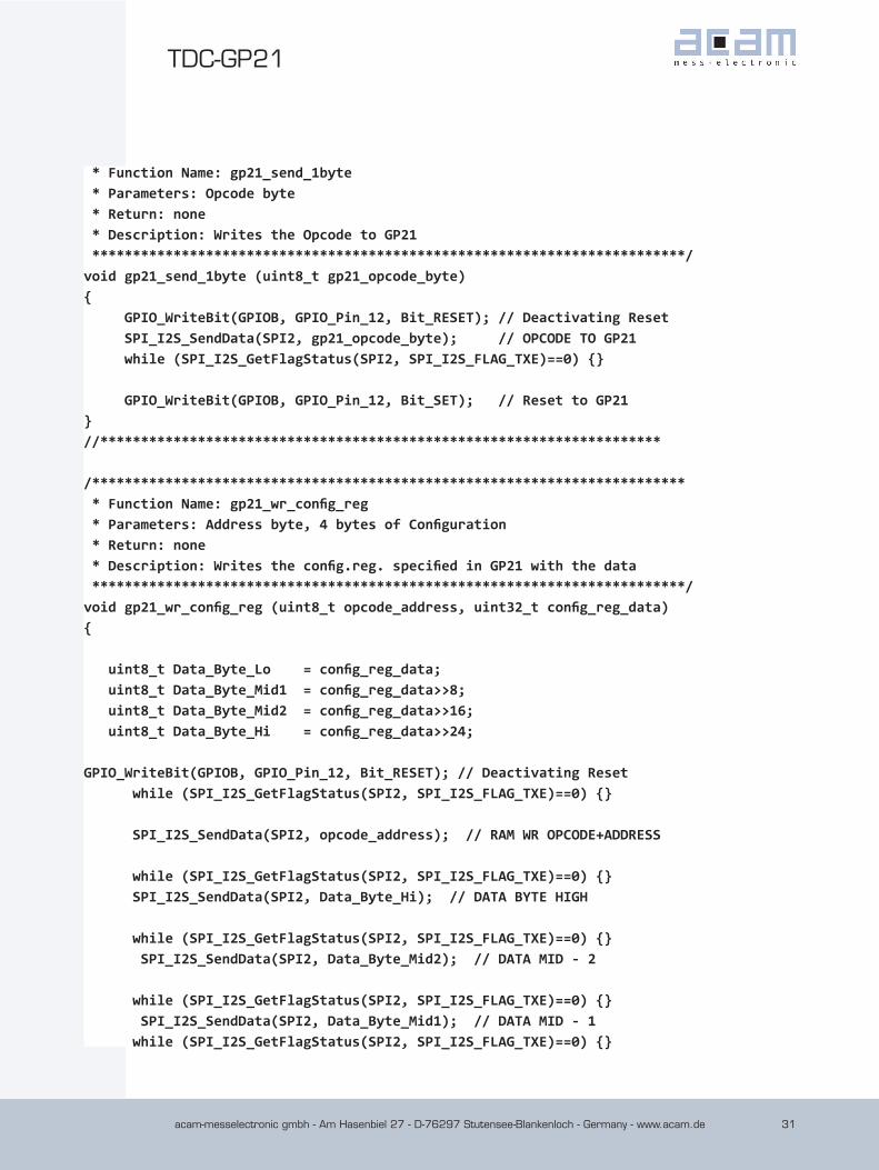
* Function Name: gp21_send_1byte * Parameters: Opcode byte * Return: none * Description: Writes the Opcode to GP21 *************************************************************************/void gp21_send_1byte (uint8_t gp21_opcode_byte){ GPIO_WriteBit(GPIOB, GPIO_Pin_12, Bit_RESET); // Deactivating Reset SPI_I2S_SendData(SPI2, gp21_opcode_byte); // OPCODE TO GP21 while (SPI_I2S_GetFlagStatus(SPI2, SPI_I2S_FLAG_TXE)==0) {} GPIO_WriteBit(GPIOB, GPIO_Pin_12, Bit_SET); // Reset to GP21}//*********************************************************************
/************************************************************************* * Function Name: gp21_wr_config_reg * Parameters: Address byte, 4 bytes of Configuration * Return: none * Description: Writes the config.reg. specified in GP21 with the data *************************************************************************/void gp21_wr_config_reg (uint8_t opcode_address, uint32_t config_reg_data){
uint8_t Data_Byte_Lo = config_reg_data; uint8_t Data_Byte_Mid1 = config_reg_data>>8; uint8_t Data_Byte_Mid2 = config_reg_data>>16; uint8_t Data_Byte_Hi = config_reg_data>>24;
GPIO_WriteBit(GPIOB, GPIO_Pin_12, Bit_RESET); // Deactivating Reset while (SPI_I2S_GetFlagStatus(SPI2, SPI_I2S_FLAG_TXE)==0) {}
SPI_I2S_SendData(SPI2, opcode_address); // RAM WR OPCODE+ADDRESS
while (SPI_I2S_GetFlagStatus(SPI2, SPI_I2S_FLAG_TXE)==0) {} SPI_I2S_SendData(SPI2, Data_Byte_Hi); // DATA BYTE HIGH
while (SPI_I2S_GetFlagStatus(SPI2, SPI_I2S_FLAG_TXE)==0) {} SPI_I2S_SendData(SPI2, Data_Byte_Mid2); // DATA MID - 2
while (SPI_I2S_GetFlagStatus(SPI2, SPI_I2S_FLAG_TXE)==0) {} SPI_I2S_SendData(SPI2, Data_Byte_Mid1); // DATA MID - 1 while (SPI_I2S_GetFlagStatus(SPI2, SPI_I2S_FLAG_TXE)==0) {}
acam-messelectronic gmbh - Am Hasenbiel 27 - D-76297 Stutensee-Blankenloch - Germany - www.acam.de32
TDC-GP21TDC
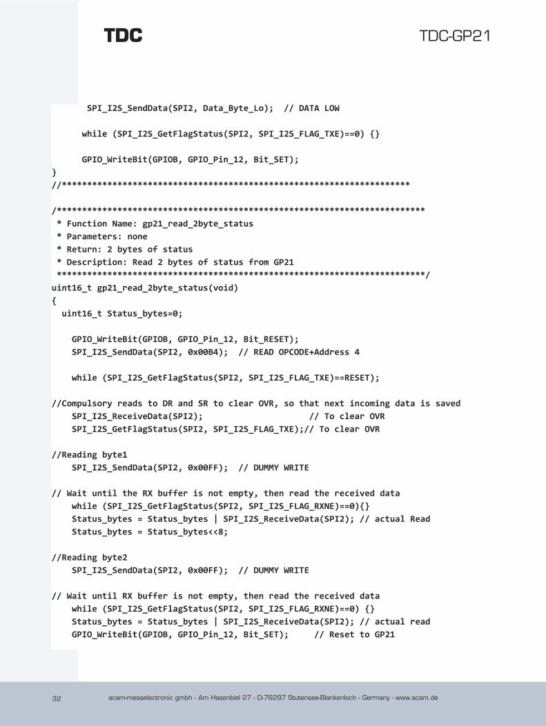
SPI_I2S_SendData(SPI2, Data_Byte_Lo); // DATA LOW
while (SPI_I2S_GetFlagStatus(SPI2, SPI_I2S_FLAG_TXE)==0) {}
GPIO_WriteBit(GPIOB, GPIO_Pin_12, Bit_SET);}//*********************************************************************
/************************************************************************* * Function Name: gp21_read_2byte_status * Parameters: none * Return: 2 bytes of status * Description: Read 2 bytes of status from GP21 *************************************************************************/uint16_t gp21_read_2byte_status(void){ uint16_t Status_bytes=0; GPIO_WriteBit(GPIOB, GPIO_Pin_12, Bit_RESET); SPI_I2S_SendData(SPI2, 0x00B4); // READ OPCODE+Address 4 while (SPI_I2S_GetFlagStatus(SPI2, SPI_I2S_FLAG_TXE)==RESET); //Compulsory reads to DR and SR to clear OVR, so that next incoming data is saved SPI_I2S_ReceiveData(SPI2); // To clear OVR SPI_I2S_GetFlagStatus(SPI2, SPI_I2S_FLAG_TXE);// To clear OVR //Reading byte1 SPI_I2S_SendData(SPI2, 0x00FF); // DUMMY WRITE // Wait until the RX buffer is not empty, then read the received data while (SPI_I2S_GetFlagStatus(SPI2, SPI_I2S_FLAG_RXNE)==0){} Status_bytes = Status_bytes | SPI_I2S_ReceiveData(SPI2); // actual Read Status_bytes = Status_bytes<<8; //Reading byte2 SPI_I2S_SendData(SPI2, 0x00FF); // DUMMY WRITE // Wait until RX buffer is not empty, then read the received data while (SPI_I2S_GetFlagStatus(SPI2, SPI_I2S_FLAG_RXNE)==0) {} Status_bytes = Status_bytes | SPI_I2S_ReceiveData(SPI2); // actual read GPIO_WriteBit(GPIOB, GPIO_Pin_12, Bit_SET); // Reset to GP21
acam-messelectronic gmbh - Am Hasenbiel 27 - D-76297 Stutensee-Blankenloch - Germany - www.acam.de 33
TDC-GP21
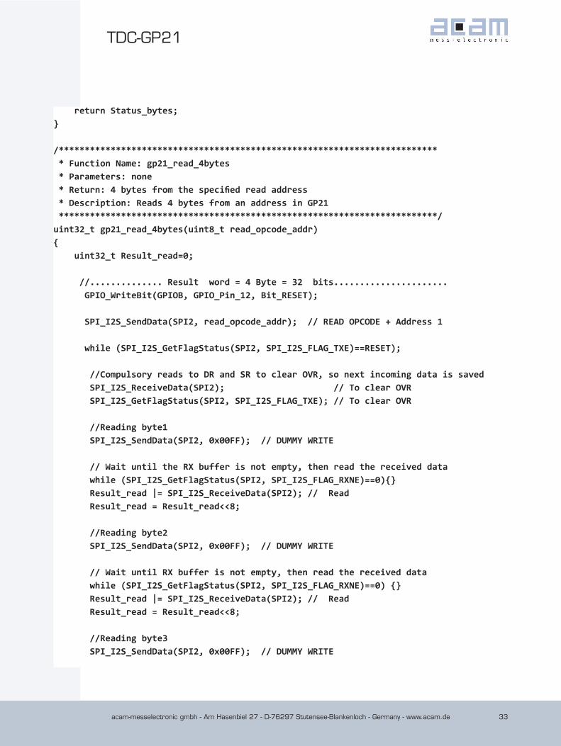
return Status_bytes;}
/************************************************************************* * Function Name: gp21_read_4bytes * Parameters: none * Return: 4 bytes from the specified read address * Description: Reads 4 bytes from an address in GP21 *************************************************************************/uint32_t gp21_read_4bytes(uint8_t read_opcode_addr){ uint32_t Result_read=0;
//.............. Result word = 4 Byte = 32 bits...................... GPIO_WriteBit(GPIOB, GPIO_Pin_12, Bit_RESET); SPI_I2S_SendData(SPI2, read_opcode_addr); // READ OPCODE + Address 1 while (SPI_I2S_GetFlagStatus(SPI2, SPI_I2S_FLAG_TXE)==RESET); //Compulsory reads to DR and SR to clear OVR, so next incoming data is saved SPI_I2S_ReceiveData(SPI2); // To clear OVR SPI_I2S_GetFlagStatus(SPI2, SPI_I2S_FLAG_TXE); // To clear OVR //Reading byte1 SPI_I2S_SendData(SPI2, 0x00FF); // DUMMY WRITE // Wait until the RX buffer is not empty, then read the received data while (SPI_I2S_GetFlagStatus(SPI2, SPI_I2S_FLAG_RXNE)==0){} Result_read |= SPI_I2S_ReceiveData(SPI2); // Read Result_read = Result_read<<8; //Reading byte2 SPI_I2S_SendData(SPI2, 0x00FF); // DUMMY WRITE // Wait until RX buffer is not empty, then read the received data while (SPI_I2S_GetFlagStatus(SPI2, SPI_I2S_FLAG_RXNE)==0) {} Result_read |= SPI_I2S_ReceiveData(SPI2); // Read Result_read = Result_read<<8; //Reading byte3 SPI_I2S_SendData(SPI2, 0x00FF); // DUMMY WRITE
acam-messelectronic gmbh - Am Hasenbiel 27 - D-76297 Stutensee-Blankenloch - Germany - www.acam.de34
TDC-GP21TDC
// Wait until the RX buffer is not empty, then read the received data while (SPI_I2S_GetFlagStatus(SPI2, SPI_I2S_FLAG_RXNE)==0){} Result_read |= SPI_I2S_ReceiveData(SPI2); // Read Result_read = Result_read<<8; //Reading byte4 SPI_I2S_SendData(SPI2, 0x00FF); // DUMMY WRITE // Wait until the RX buffer is not empty, then read the received data while (SPI_I2S_GetFlagStatus(SPI2, SPI_I2S_FLAG_RXNE)==0){} Result_read |= SPI_I2S_ReceiveData(SPI2); // Read GPIO_WriteBit(GPIOB, GPIO_Pin_12, Bit_SET); // Reset to GP21 return Result_read;} //*********************************************************************
/************************END OF FILE**********************/
7 Literature References
acam-messelectronic gmbh - “TDC-GP21 Datasheet“
http://www.acam.de/download-center/time-to-digital converters
acam-messelectronic gmbh - “GP2 to GP21 migration guide“
http://www.acam.de/download-center/time-to-digital converters
acam-messelectronic gmbh - “Temperature port investigations of TDC-GP2“
http://www.acam.de/download-center/time-to-digital converters
8 Revision History19.10.2011 Chapters 5 & 6 revised.

acam-messelectronic gmbh - Am Hasenbiel 27 - D-76297 Stutensee-Blankenloch - Germany - www.acam.de 35
TDC-GP21

Data Sheet
acam-messelectronic gmbh
Am Hasenbiel 27
76297 Stutensee-Blankenloch
Germany / Allemagne
ph. +49 7244 7419 - 0
fax +49 7244 7419 - 29
e-mail: [email protected]
www.acam.de