tilting multicopter rotors for increased power efficiency...
TRANSCRIPT

Tilting multicopter rotors for increased power efficiency and yawauthority
Conrad Holda1, Behnam Ghalamchi1,2, and Mark W. Mueller1
Abstract— We demonstrate that a simple mechanical mod-ification increasing the yaw authority of a multicopter leadsto a reduction in mechanical power consumption in flight.Increased yaw authority is achieved by tilting the propellers’thrust directions in the direction that increases their yaw torque.The power reduction is achieved in noisy environments, wherethe vehicle experiences external disturbances. This is due tothe lower variance in motor forces required for yaw control,and the convex functional relationship between force andpower consumed. We present a theoretical analysis motivatinga reduction in power consumed to first order in increasingpropeller tilt, in addition to increasing agility. Experimentsvalidate the idea, where the measured electric power is usedinstead of the mechanical power consumption. Experiments areperformed on two quadcopters of very different scales, withmasses ranging from 45g to 1.15kg, with both showing a powerimprovement.
I. INTRODUCTION
Unmanned aerial vehicles (UAVs) have continued todemonstrate their efficacy within a wide range of applica-tions. As the usage of UAVs continues to grow, researchershave increased their efforts in optimizing UAV performance,and a primary limitation for current vehicles is their flighttime. A reduction in power consumption is thus a significantfactor in improved UAV performance as it directly translatesto longer potential flight times.
A primary approach to improving efficiency is throughnovel designs. For example, tail-sitter vehicles utilize verticalpropulsion to perform take-off and landing, but use a wingto fly over long distances [1]–[4]. Other designs decreasepower consumption by transitioning to a different style of lo-comotion to reduce the amount of time the UAV is airborne.These hybrid designs allow the vehicle to alternate betweenmodes that are the most optimal for the task being performed.Some researchers incorporate jumping and gliding [5], flyingand crawling [6], and flying, rolling, and floating [7]. All ofthese combinations have the potential to benefit the efficiencyof the UAV; however, including two drastically differentmodes on a single small vehicle may significantly increase itsmechanical complexity and total mass, which in turn makesthe vehicles a potentially greater safety risk. Other work ismotivated by nature, e.g [8] and [9].
The study conducted in this paper proposes a simplemechanical modification to the standard quadcopter design,which is shown to simultaneously increase the vehicle’sagility and reduce its power consumption, while requiring
1Mech. Eng. Dept., University of California Berkeley, USA.2Mech. Eng. Dept., Lappeenranta University of Technology, Finland.
conradholda,behnam.ghalamchi,[email protected]
no additional actuators or aerodynamic surfaces. The designincorporates tilting the motors at a fixed angle in the directionthat increases the yaw torque from the given actuator. Thistilting of the motors requires a greater nominal thrust fromeach motor for the vehicle to remain at a hover, which wouldlead to an increase in power consumption in a disturbance-free world. However, in the realistic case of disturbances andnoise acting on the vehicle, the motor tilt allows the multi-copter to reject disturbances with smaller thrust variations,due to the greater yaw torque authority. Because the thrustusage of a multicopter is related to the power consumptionby a convex function, a greater variance in thrust increasesthe power consumption of the multicopter. We derive atheoretical basis for the reduction in power consumption,and validate this through experiments. The experiments aredone on two vehicles of very different scales, with the largervehicle’s mass 25 times greater than the smaller vehicle.
II. MODELLING
We consider a quadcopter with propellers arranged in arotationally symmetric pattern about the vehicle’s center ofmass, as shown in Fig. 1, with the body-fixed coordinatesystem defined by the triad 1B , 2B , and 3B . Each of thevehicle’s four propellers is tilted around the vector thatconnects the centre of the propeller to the centre of mass,such that the propeller’s normal vector ei is at an angle δ withrespect to the body-fixed 3B direction. For each propeller, thetilt is in that direction that would increase the resulting yawtorque. Thus, in the body-fixed coordinate system, the unitvectors ei perpendicular to the propeller’s planes of rotation
Fig. 1. Diagram of a quadcopter with tilted propellers for increased yawauthority. Each propeller is tilted about the arm connecting to the center ofmass by the same angle δ. The propellers are tilted so that their producea torque about the body-fixed 3B axis in the same direction as the torquedue to the propeller’s rotation.
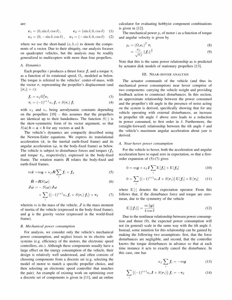
are:
e1 = (0, sin δ, cos δ) , e2 = (sin δ, 0, cos δ) (1)e3 = (0,− sin δ, cos δ) , e4 = (− sin δ, 0, cos δ) (2)
where we use the short-hand (a, b, c) to denote the compo-nents of a vector. Due to their ubiquity, our analysis focuseson quadcopter vehicles, but the analysis may be readilygeneralized to multicopters with more than four propellers.
A. Dynamics
Each propeller i produces a thrust force fi and a torque τias a function of its rotational speed, Ωi, modeled as below.The torque is referred to the vehicles’ center-of-mass, withthe vector ri representing the propeller’s displacement (and‖ri‖ = r):
fi = κfΩ2iei (3)
τi = (−1)i+1κτfi + S(ri)fi (4)
with κf and κτ being aerodynamic constants dependingon the propellers [10] – this assumes that the propellersare identical up to their handedness. The function S(·) isthe skew-symmetric form of its vector argument, so thatS(a) b = a× b for any vectors a and b.
The vehicle’s dynamics are compactly described usingthe Newton-Euler equations. We express its translationalacceleration (x, in the inertial earth-fixed frame) and itsangular acceleration (ω, in the body-fixed frame) as below.The vehicle is subject to disturbance forces and torques (fd
and torque τd, respectively), expressed in the body-fixedframe. The rotation matrix R relates the body-fixed andearth-fixed frames.
mx =mg + κfR∑i
fi + fd (5)
R =RS(ω) (6)Jω =− S(ω)Jω
+∑i
((−1)i+1κτfi + S(ri)fi
)+ τd (7)
wherein m is the mass of the vehicle, J is the mass momentof inertia of the vehicle (expressed in the body-fixed frame),and g is the gravity vector (expressed in the world-fixedframe).
B. Mechanical power consumption
For analysis, we consider only the vehicle’s mechanicalpower consumption, and neglect losses in its electric sub-systems (e.g. efficiency of the motors, the electronic speedcontrollers, etc.). Although these components usually have alarge effect on the energy consumption of the vehicle, theirdesign is relatively well understood, and often consists ofchoosing components from a discrete set (e.g. selecting themodel of motor to match a specific propeller choice, andthen selecting an electronic speed controller that matchesthe pair). An example of existing work on optimizing overa discrete set of components is given in [11], and an online
calculator for evaluating hobbyist component combinationsis given in [12].
The mechanical power pi of motor i as a function of torqueand angular velocity is given by
pi = (Ωiei)Tτi (8)
=κτ√κf
‖fi‖32 (9)
Note that this is the same power relationship as is predictedby actuator disk models of stationary propellers [13].
III. NEAR-HOVER ANALYSIS
The actuator commands of the vehicle (and thus itsmechanical power consumption) near hover comprise oftwo components: carrying the vehicle weight and providingfeedback action to counteract disturbances. In this section,an approximate relationship between the power consumedand the propeller’s tilt angle in the presence of noise actingon the system is derived, specifically showing that for anyvehicle operating with external disturbances, an increasein propeller tilt angle δ above zero leads to a reductionin power consumed, to first order in δ. Furthermore, the(straight-forward) relationship between the tilt angle δ andthe vehicle’s maximum angular acceleration about yaw isderived.
A. Near-hover power consumption
For the vehicle to hover, both the acceleration and angularacceleration have to equal zero in expectation, so that a first-order expansion of (5)-(7) gives
0 = mg + κfI∑i
E [fi] + E [fd] (10)
0 =∑i
((−1)i+1κτI + S(ri)
)E [fi] + E [τd] (11)
where E [·] denotes the expectation operator. From thisfollows that, if the disturbance force and torque are zero-mean, due to the symmetry of the vehicle
E [‖fi‖] =m ‖g‖4 cos δ
(12)
Due to the nonlinear relationship between power consump-tion and thrust (9), the expected power consumption willnot (in general) scale in the same way with the tilt angle δ.Instead, some intuition for this relationship can be gained bymaking the following two assumptions: first, that the forcedisturbances are negligible, and second, that the controllerknows the torque disturbances in advance so that at eachtime instance it acts to exactly cancel the disturbance. Inthis case, one has
κf
∑i
fi = −mg (13)
∑i
((−1)i+1κτI + S(ri)
)fi = −τd (14)
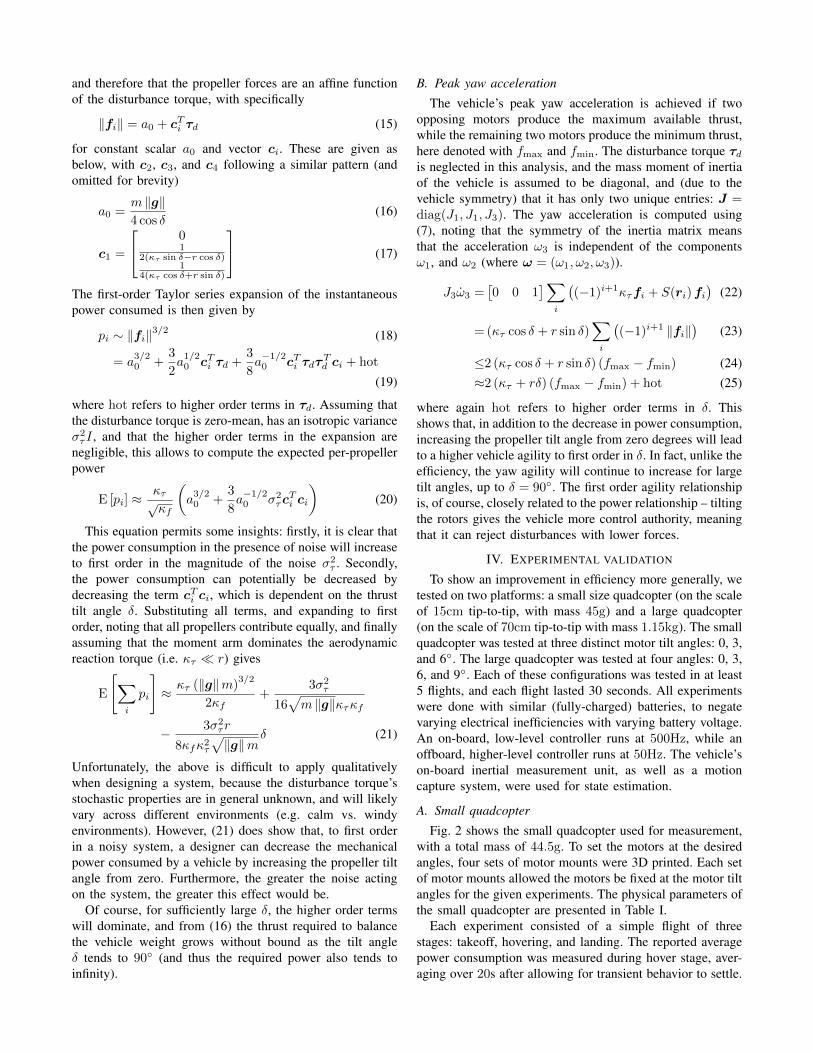
and therefore that the propeller forces are an affine functionof the disturbance torque, with specifically
‖fi‖ = a0 + cTi τd (15)
for constant scalar a0 and vector ci. These are given asbelow, with c2, c3, and c4 following a similar pattern (andomitted for brevity)
a0 =m ‖g‖4 cos δ
(16)
c1 =
01
2(κτ sin δ−r cos δ)1
4(κτ cos δ+r sin δ)
(17)
The first-order Taylor series expansion of the instantaneouspower consumed is then given by
pi ∼ ‖fi‖3/2 (18)
= a3/20 +
3
2a1/20 cTi τd +
3
8a−1/20 cTi τdτ
Td ci + hot
(19)
where hot refers to higher order terms in τd. Assuming thatthe disturbance torque is zero-mean, has an isotropic varianceσ2τI , and that the higher order terms in the expansion are
negligible, this allows to compute the expected per-propellerpower
E [pi] ≈κτ√κf
(a3/20 +
3
8a−1/20 σ2
τcTi ci
)(20)
This equation permits some insights: firstly, it is clear thatthe power consumption in the presence of noise will increaseto first order in the magnitude of the noise σ2
τ . Secondly,the power consumption can potentially be decreased bydecreasing the term cTi ci, which is dependent on the thrusttilt angle δ. Substituting all terms, and expanding to firstorder, noting that all propellers contribute equally, and finallyassuming that the moment arm dominates the aerodynamicreaction torque (i.e. κτ r) gives
E
[∑i
pi
]≈ κτ (‖g‖m)
3/2
2κf+
3σ2τ
16√m ‖g‖κτκf
− 3σ2τr
8κfκ2τ
√‖g‖m
δ (21)
Unfortunately, the above is difficult to apply qualitativelywhen designing a system, because the disturbance torque’sstochastic properties are in general unknown, and will likelyvary across different environments (e.g. calm vs. windyenvironments). However, (21) does show that, to first orderin a noisy system, a designer can decrease the mechanicalpower consumed by a vehicle by increasing the propeller tiltangle from zero. Furthermore, the greater the noise actingon the system, the greater this effect would be.
Of course, for sufficiently large δ, the higher order termswill dominate, and from (16) the thrust required to balancethe vehicle weight grows without bound as the tilt angleδ tends to 90 (and thus the required power also tends toinfinity).
B. Peak yaw acceleration
The vehicle’s peak yaw acceleration is achieved if twoopposing motors produce the maximum available thrust,while the remaining two motors produce the minimum thrust,here denoted with fmax and fmin. The disturbance torque τdis neglected in this analysis, and the mass moment of inertiaof the vehicle is assumed to be diagonal, and (due to thevehicle symmetry) that it has only two unique entries: J =diag(J1, J1, J3). The yaw acceleration is computed using(7), noting that the symmetry of the inertia matrix meansthat the acceleration ω3 is independent of the componentsω1, and ω2 (where ω = (ω1, ω2, ω3)).
J3ω3 =[0 0 1
]∑i
((−1)i+1κτfi + S(ri)fi
)(22)
=(κτ cos δ + r sin δ)∑i
((−1)i+1 ‖fi‖
)(23)
≤2 (κτ cos δ + r sin δ) (fmax − fmin) (24)≈2 (κτ + rδ) (fmax − fmin) + hot (25)
where again hot refers to higher order terms in δ. Thisshows that, in addition to the decrease in power consumption,increasing the propeller tilt angle from zero degrees will leadto a higher vehicle agility to first order in δ. In fact, unlike theefficiency, the yaw agility will continue to increase for largetilt angles, up to δ = 90. The first order agility relationshipis, of course, closely related to the power relationship – tiltingthe rotors gives the vehicle more control authority, meaningthat it can reject disturbances with lower forces.
IV. EXPERIMENTAL VALIDATION
To show an improvement in efficiency more generally, wetested on two platforms: a small size quadcopter (on the scaleof 15cm tip-to-tip, with mass 45g) and a large quadcopter(on the scale of 70cm tip-to-tip with mass 1.15kg). The smallquadcopter was tested at three distinct motor tilt angles: 0, 3,and 6. The large quadcopter was tested at four angles: 0, 3,6, and 9. Each of these configurations was tested in at least5 flights, and each flight lasted 30 seconds. All experimentswere done with similar (fully-charged) batteries, to negatevarying electrical inefficiencies with varying battery voltage.An on-board, low-level controller runs at 500Hz, while anoffboard, higher-level controller runs at 50Hz. The vehicle’son-board inertial measurement unit, as well as a motioncapture system, were used for state estimation.
A. Small quadcopter
Fig. 2 shows the small quadcopter used for measurement,with a total mass of 44.5g. To set the motors at the desiredangles, four sets of motor mounts were 3D printed. Each setof motor mounts allowed the motors be fixed at the motor tiltangles for the given experiments. The physical parameters ofthe small quadcopter are presented in Table I.
Each experiment consisted of a simple flight of threestages: takeoff, hovering, and landing. The reported averagepower consumption was measured during hover stage, aver-aging over 20s after allowing for transient behavior to settle.

Fig. 2. The small quadcopter used in experiments.
TABLE IPHYSICAL PARAMETERS OF SMALL QUADCOPTER
Mass m 44.5grArm length l 50mmAerodynamic constant for angular speedsquard to thrust κf 4.14e-8 Ns2
rad2
Aerodynmaic constant for thrust to torque κτ 0.001Mass moment of inertia about 1B axis J1 30e− 6kg.m2
Mass moment of inertia about 2B axis J2 30e− 6kg.m2
Mass moment of inertia about 3B axis J3 60e− 6kg.m2
Fig. 3 shows the power measurements during the flight. Thistest resulted in one data point from the averaged data duringthe hovering interval of the flight.
Fig. 4 shows the normalized power consumption of smallquadcopter. For easier comparison, all reported power con-sumption values are normalized by the average power con-sumption when the motors were tilted at 0.
From the experimental test results, the small quadcoptersaw a 2% decrease in power consumption compared to thetraditional, tilt-free configuration. Tilting the motors at δ =6 does not show much improvement in power consumption,but still yields a more agile mulitcopter (with an increase inmaximum yaw acceleration of 72% compared to the 3 degreemotor tilt angle design).
B. Large quadcopter
A second set of experiments was conducted on a largervehicle, shown in Fig. 5. The vehicle was constructed usinga bar with circular cross-section for the motor arms, allowingvarious motor tilt angles to be set more freely and precisely.The physical parameters of the quadcopter is presented inTable II.
The normalized power consumption for four different tiltangles is presented in Fig. 6. Compared with results for thesmall quadcopter, the larger vehicle shows less sensitivity tothe tilt angle changes, and only a 0.5% improvement in thepower consumption efficiency was observed. This may be
Fig. 3. Recording of the electric power consumption at hover. The value ofthe power consumption from this flight was obtained using average powerconsumption for the time between the dotted black lines.
0 1 2 3 4 5 6
motor tilt angle (degree)
0.92
0.94
0.96
0.98
1
1.02
1.04
Norm
aliz
ed p
ow
er
consum
ption
Fig. 4. Normalized power consumption of the small quadcopter. Each dotrepresents the average power consumption of one flight test and the solid lineconnects the average power consumption of all tests at each configuration.
reconciled with (21), by examining the term that is affine intilt angle δ. This term scales inversely proportionally to theaerodynamic constant for thrust to torque squared κτ , andinversely proportionally to the square root of the vehicle’smass – as the larger vehicle has both a greater mass and ahigher aerodynamic constant κτ , a lesser effect is predicted.
Experiments were also conducted where external distur-bances were applied using an air blower to disturb the vehicleduring flight (thus increasing σT in (21)), with the resultsshown in Fig. 7. As expected, the increase in efficiency waslarger for a greater disturbance acting on the quadcopter.Applying additional disturbance to the vehicle, it can beseen that the power consumption decreases around 1.5% ata tilt angle of 3. Furthermore, for this tilt angle of 3, thelarge vehicle’s maximum yaw acceleration is increased by72% compared to the tilt-free design. The experiments alsoshowed increased power consumption for larger tilt angles– at these angles the higher order terms of (20) start todominate.

Fig. 5. The large quadcopter vehicle used in the experiments to test theefficiency of tilted motors. A 15cm ruler is placed in front of the vehiclefor scale.
TABLE IIPHYSICAL PARAMETERS OF LARGE QUADCOPTER
Mass m 1.15kgArm length l 0.225mAerodynamic constant for angular speedsquard to thrust κf 1.245e-5 Ns2
rad2
Aerodynmaic constant for thrust to torque κτ 0.0164Mass moment of inertia about 1B axis J1 10.6e− 6kg.m2
Mass moment of inertia about 2B axis J2 10.6e− 6kg.m2
Mass moment of inertia about 3B axis J3 19.4− 6kg.m2
V. CONCLUSION
Power efficiency is a primary concern in the design ofUAVs, and improvements in efficiency (and thus increasesin flight time/range) offer potentially immediate economicadvantage. The proposed modification, tilting the thrust axesto increase yaw authority, is shown to decrease power con-sumption, both through a stochastic analysis, and throughexperiments. Notably, the power consumption is shown todecrease even though the average thrust force increases.Specifically, the experiments conducted in this study showedpower improvements on the order of 2% in hover, with tiltangles on the order of 3. Future work will consider theeffect of the motor tilt on lateral vehicle motions, and on the
0 1 2 3 4 5 6 7 8 9
motor tilt angle (degree)
0.985
0.99
0.995
1
1.005
1.01
1.015
Norm
aliz
ed p
ow
er
consum
ption
Fig. 6. Normalized power consumption of the custom vehicle. Each dotrepresents the average power consumption of one flight test and the solid lineconnects the average power consumption of all tests at each configuration.
0 1 2 3 4 5 6 7 8 9
motor tilt angle (degree)
0.97
0.98
0.99
1
1.01
1.02
1.03
Norm
aliz
ed p
ow
er
consum
ption
Fig. 7. Normalized power consumption of custom vehicle with additionaldisturbance from an external air blower. Each dot represents the averagepower consumption of one flight test and the solid line connects the averagepower consumption of all tests at each configuration.
vehicle’s roll and pitch dynamics.
VI. ACKNOWLEDGEMENT
This work was supported by the UC Berkeley Dept. ofMechanical Engineering, and the Powley Fund. The authorswish to acknowledge Markus Hehn and Flavio Fontanafor discussions on the topic of power consumption, andall contributors to the experimental system used (a listis available at hiperlab.berkeley.edu/members/),especially Nemo Jin.
REFERENCES
[1] R. H. Stone and G. Clarke, “Optimization of transitionmaneuvers for a tail-sitter unmanned air vehicle (UAV),” inAustralian international aerospace congress, vol. 4, 2001.
[2] D. Kubo and S. Suzuki, “Tail-sitter vertical takeoff and land-ing unmanned aerial vehicle: Transitional flight analysis,”Journal of Aircraft, vol. 45, no. 1, pp. 292–297, 2008.
[3] R. Bapst, R. Ritz, L. Meier, and M. Pollefeys, “Designand implementation of an unmanned tail-sitter,” in IEEE/RSJInternational Conference on Intelligent Robots and Systems(IROS), IEEE, 2015, pp. 1885–1890.
[4] R. Ritz and R. D’Andrea, “A global controller for flyingwing tailsitter vehicles,” in IEEE International Conferenceon Robotics and Automation (ICRA), IEEE, 2017, pp. 2731–2738.
[5] M. A. Woodward and M. Sitti, “Multimo-bat: A biolog-ically inspired integrated jumping–gliding robot,” The In-ternational Journal of Robotics Research, vol. 33, no. 12,pp. 1511–1529, 2014.
[6] L. Daler, J. Lecoeur, P. B. Hhlen, and D. Floreano, “A flyingrobot with adaptive morphology for multi-modal locomo-tion,” in IEEE/RSJ International Conference on IntelligentRobots and Systems (IROS), IEEE, 2013, pp. 1361–1366.
[7] K. Kawasaki, M. Zhao, K. Okada, and M. Inaba, “Muwa:Multi-field universal wheel for air-land vehicle with quadvariable-pitch propellers,” in IEEE/RSJ International Confer-ence on Intelligent Robots and Systems (IROS), IEEE, 2013,pp. 1880–1885.
[8] J.-H. Han, J.-S. Lee, and D.-K. Kim, “Bio-inspired flappingUAV design: A university perspective,” in Proc. of SPIE Vol,vol. 7295, 2009, pp. 72951I-1–72951I-12.

[9] R. J. Wood, “The first takeoff of a biologically inspired at-scale robotic insect,” IEEE Transactions on Robotics, vol.24, no. 2, pp. 341–347, 2008.
[10] P. Pounds, R. Mahony, P. Hynes, and J. Roberts, “Designof a four-rotor aerial robot,” in Australasian Conference onRobotics and Automation, vol. 27, 2002, p. 29.
[11] C. Ampatis and E. Papadopoulos, “Parametric design andoptimization of multi-rotor aerial vehicles,” in Applications
of Mathematics and Informatics in Science and Engineering,Springer, 2014, pp. 1–25.
[12] M. Mller. (2017). eCalc – the most reliable electric motorcalculator on the web for RC pilots, [Online]. Available:https://ecalc.ch/ (visited on 08/01/2017).
[13] B. W. McCormick, Aerodynamics Aeronautics and FlightMechanics. John Wiley & Sons, Inc, 1995.