tilt-up construction - archive.org
TRANSCRIPT


TILT-UP CONSTRUCTION
BY
RICHARD E. CROMPTON
A REPORT PRESENTED TO THE GRADUATE COMMITTEEOF THE DEPARTMENT OF CIVIL ENGINEERING INPARTIAL FULFILLMENT OF THE REQUIREMENTSFOR THE DEGREE OF MASTER OF ENGINEERING
UNIVERSITY OF FLORIDA
SPRING 1992 T256878

6./

TABLE OF CONTENTS
LIST OF FIGURES ill
CHAPTER ONE - INTRODUCTION TO TILT-UP CONSTRUCTION '
1
Definition of Tilt-up Construction 1
Advantages of Tilt-up Construction 1
History of Tilt-up Construction 3
Typical Uses for Tilt-up Buildings 3
CHAPTER TWO - PLANNING THE TILT-UP BUILDING 5
When to Use Tilt-up Construction 5
Will There be Enough Casting Space? 6
Other Considerations for Tilt-up 10
CHAPTER THREE - THE FLOOR SLAB AND CASTING SURFACE 12The Concrete Floor Slab 12Cure Coats and Bondbreakers 12
CHAPTER FOUR - CONSTRUCTING THE TILT-UP PANELS 16Edge Forms 16Reinforcement 18Sandwich Panels 18Lifting Systems and Inserts 2
CHAPTER FIVE - ARCHITECTURAL TREATMENTS 25Types of Architectural Treatments 2 5
Exposed Aggregate Finishes 2 5
Form Liners 27Rustication and Paint 2 9
Stucco and Insert Decorative Rocks 3
CHAPTER SIX - RIGGING, LIFTING, AND PLACING TILT-UP 33Preplanning 3 3
Rigging for the Lift 33Making the Lift 39Plumbing Panels 41Temporary Bracing 4 3
CHAPTER SEVEN - CONNECTIONS FOR TILT-UP CONSTRUCTION .... 48Design Considerations 48Types of Connections 49Foundation Connections 50Panel to Panel Connections 52Roof and Floor Connections 54
CONCLUSION 62
REFERENCES 63
BIBLIOGRAPHY 64
ii


LIST OF FIGURES
Figure 1: Panels Placed in Rows 7
Figure 2: Casting Slab for Building with Small Footprint . 8
Figure 3 : Typical Panel Layout 9
Figure 4 : An Example of How to Form the Edge of a Panel . . 17Figure 5: Sandwich Panels Have a Core of Insulation
Surrounded by Concrete 19Figure 6: Ground Release Hardware Before Attaching to
Panel 22Figure 7: Ground Release Hardware attached to panel .... 22Figure 8: Exposed Aggregate Finishes Can be Cast Two Ways . 2 6
Figure 9: Typical Form Liner 28Figure 10: Rustication Used to Highlight Painted Areas ... 30Figure 11: An Example of a Panel using Trompe L'oeil .... 32Figure 12: Crane Rigged With 4 Rows Across and 2 Rows High . 3 5Figure 13: Crane Rigged With 4 Rows Across and 1 Row High . . 35Figure 14 : An Easy Way to Switch From a 3 Hi to a 2 Hi Rigging
Configuration 37Figure 15: Changing From a 4 Hi to a 2 Hi Rigging
Configuration 3 8
Figure 16: Crane Performing a "Suicide Lift" or a "BlindPick" 40
Figure 17: Crane Operator Can See the Rigging When PanelLifted This Way 41
Figure 18: Plumbing Blocks Can be Used to Hold a PanelUpright 43
Figure 19: Temporary Panel Bracing 45Figure 20: Knee Bracing, Lateral Bracing, and End Bracing . . 46Figure 21: Panel to Foundation Connection 51Figure 22: Panel to Foundation Connection 52Figure 23: Rigid and Nonrigid Connections 53Figure 24: Welded Panel-Panel Connections 54Figure 25: Recessed Floor/Roof Connection 55Figure 26: Angle Seat Used to Support Metal Joist 56Figure 27: Wood Joist Supported on Wood Ledger 57Figure 28: Wood Beam Supported in Steel Shoe 58Figure 29: Steel Beam on Pillaster 60Figure 30: Double Tee on Concrete Ledger 61
in


CHAPTER ONEINTRODUCTION TO TILT-UP CONSTRUCTION
1.
1
Definition of Tilt-up Construction
Tilt-up construction is a special form of precast
concrete construction. The technique is used for constructing
buildings by prefabricating concrete wall sections (panels) in
a horizontal position on either the building's floor slab or
on a temporary casting slab. Once the wall sections have
cured, they are tilted to a vertical position using a mobile
crane, they are temporarily braced in their final upright
position, and finally, they are tied into the building's roof
and floor system to become an integral part of the finished
structure.
Tilt-up is a fast, simple, and economical technique of
construction which, in the past, has been used most commonly
on one-story buildings. Today, however, buildings as high as
six stories are being cast and tilted into position.
1.2 Advantages of Tilt-up Construction
The economic advantage of tilt-up lies in its simplicity
and speed of construction. Compared to other forms of precast
concrete construction, tilt-up eliminates the need for
expensive transportation of building components from the
precast plant to the job-site. By casting panels at the
project site, panels can be designed much larger than those
that must be transported from a precast concrete plant. By


spending time up front in the planning stage of a project, the
critical factors of constructing a tilt-up building are
carefully considered to minimize total construction time. By
applying skillful panel casting layout plans, the panel
erection sequence can be accomplished very quickly in an
assembly line type operation. Additionally, since the panel
erection sequence can be set up to run quickly, the total time
required for renting an expensive crane is minimized. Since
the panels are cast horizontally at ground level, there is no
expensive vertical formwork, and the formwork that is required
is accomplished quickly and safely since the carpenters and
steelworkers can work at ground level.
Tilt-up buildings are inherently low maintenance since
the concrete surfaces can be left unpainted and are not
affected by moisture or weathering. Although the typical
early generation tilt-up buildings tended to be simple and
plain boxlike structures, today's tilt-up buildings have a
limitless freedom of design for both shape and architectural
treatments. In fact, it is difficult to tell that many
recently constructed buildings are made by using the tilt-up
technique. Tilt-up buildings can be very flexible since
panels can be easily removed and relocated if future building
expansions become necessary. Finally, tilt-up panels of 5-1/2
to 6 inches thick have the inherent fire safety rating of
concrete buildings and "will provide a fire endurance of two
hours or more" (1:3).


1.
3
History of Tilt-up Construction
The earliest recorded case of "job-site precasting began
as early as 1906 when a railroad bridge, which had been
precast [on site], was successfully set in place by a railroad
crane" (2:5). Following the first successful use of the tilt-
up technique, several small tilt-up structures were built over
the next two decades by using tilting platforms or by using
railroad cranes. Due to the high expense of laying railroad
track for the heavy railroad crane or the expense of
constructing the tilting platforms, tilt-up did not catch on
as a practical technique until 1946. The significance of this
date is simple: modern mobile cranes were developed during the
period from 1941-1945 during World War II. After the war,
tilt-up construction became a more popular construction
technique since panel erection could be rapidly accomplished
by the use of mobile cranes.
1.4 Typical Uses for Tilt-up Buildings
Tilt-up construction can be used for any type of low- to
mid-rise building. The most common applications are found in
warehouses. Warehouse buildings are typically 22 to 3 feet
high, they are rectangular in shape, and they have a large
floor area. These design aspects of warehouses readily lend
themselves to tilt-up construction since the wall heights
allow economical panel thicknesses, and the large floor areas
provide plenty of room for casting the precast walls. By


using load-bearing tilt-up walls with a light roof system, the
needs of a typical warehouse can be realized economically with
tilt-up.
Many of today's mid-rise office buildings are constructed
using tilt-up. By applying the myriad architectural
treatments available, designers can provide buildings that
project the professional image desired by any company, and the
building can be constructed quickly and economically. A few
of tilt-up' s most recent markets are in constructing shopping
malls, mid-rise apartments, condominiums, townhouses, and
hotels.


CHAPTER TWOPLANNING THE TILT-UP BUILDING
2 . 1 When to Use Tilt-up Construction
The decision of which method of construction to use for
a building is influenced by several factors. The most
significant factor is the cost of the building. A building's
owner typically will not be as concerned with his new
building's construction method as he will be with the
building's bottom-line cost. Tilt-up construction is not a
technique that a contractor can arbitrarily decide to use on
any reinforced concrete structure. The designer must
specifically design the building from the very beginning with
the intention of having it constructed using the tilt-up
method. Since tilt-up panels typically experience stresses
from three to four times higher during lifting than they do
once they are placed into position, it is extremely important
for the designer to consider the critical lifting loads during
the design process. The overall cost of the building is going
to be controlled by more than just the total material cost.
For vertical concrete construction, a major portion of the
total building cost can be spent in formwork and labor. If
the owner and the designer decide concrete is the material of
choice for a building, then tilt-up* s potential savings for
expensive formwork, labor, and time may become an attractive
alternative.


2 .2 Will There be Enough Casting Space?
In addition to cost considerations, there are other site
dependant considerations that must be weighed. A crowded job-
site in an area like New York City would not readily lend
itself to using tilt-up construction. The problems with a
site that is bordered by other buildings and busy roads are
the limited working room for the crane and the limited casting
area. It is easy to visualize a building that is relatively
tall with a small footprint, and a building with these
dimensions in a crowded location cannot economically be
constructed using tilt-up since the floor slab is too small to
be used for casting the wall panels. Actually, there are two
solutions for using tilt-up construction on a project where
the building's floor slab is too small for casting wall panels
that are tall enough to span from the ground to the roof. One
solution is to construct smaller wall panels and then actually
place panels on top of each other in their final position as
shown in figure 1. The drawback of this system is the
difficulty in safely bracing the panels during the
construction. The second solution is to construct separate
concrete casting slabs on the job site, and then use these
slabs for constructing the building's wall panels.


Panels placed in double layer
K\\\\\\\\\\\\\\\\\\S\\\\\\\\\\\\^^\\\\\\\\\^X?1\ffr
DoorOpening
Floor Slab7
Figure l: Panels Placed in Rows
To minimize the number of additional casting slabs
required, the wall panels can be stack cast on top of each
other which means that wall panels are actually poured on top
of one another similarly to stacking a deck of playing cards
on top of each other one card at a time as shown in figure 2.
The major problems with using a separate casting slab are the
additional expense required for constructing the additional
casting slabs, and the panels are not cast near their final
position which means more time and effort must be used to move
the panels to their final position along the building's wall.


Tilt-up Panels
^/////////////^///////////////^aK///////////////////////////////zza
Side View of Casting Slab
with Slacked Panels
Building Slab
Top View ol Building Slab
with Separate Casting Slabs
Figure 2: Casting Slab for Building withSmall Footprint
A typical tilt-up building will not be affected by nearby
buildings or by a floor slab that is too small to be used as
a casting bed. For a typical tilt-up building, the floor slab
will be constructed first, and then the individual wall panels
will be formed and poured directly on top of the floor slab.
"A successful tilt-up project depends on proper planning to
avoid unnecessary delays and to provide maximum safety.
Layout of panels on the casting slab, placement of erection
and bracing inserts, movement of the crane, and rigging of the
crane to the panel must all be carefully coordinated" (3:23).
Figure 3 shows a typical layout for tilt-up panels on a
building floor slab. The panels are cast as close to their
8


final upright position as possible to make the actual lifting
operation as quick and efficient as possible. A few items
need to be considered while planning the layout for casting
the wall panels. It is critical to leave a space along the
edge of the building slab to allow the crane access to the
middle portion of the floor slab when the crane arrives to
lift the panels. This is not necessary if the panels will be
lifted from the outside of the building, but usually the crane
will lift panels from the inside of the building to take
advantage of the firm operating surface of the floor slab.
Corner panels are usually stack cast on top of each other to
keep them as close as possible to their final position.
Finally, any overhead power lines, adjacent construction, or
weak areas in the slab must be considered before the lifting
can safely begin.
! Indicates single mat panda
lilHM Indloatae ataofc oaal panaia
8paoa forCrana Aooaaa
Top View of Panel Casting Positions
on Building Floor Slab
Figure 3: Typical Panel Layout

2 . 3 Other Considerations for Tilt-up
There are many items that must be considered when
planning a tilt-up building in addition to site location
considerations and panel layout. When the panels are being
cast on either the floor slab or the casting bed, a
bondbreaker must be used to keep the concrete panels from
sticking to the casting surface. Also, most panels are poured
with the exterior face down, so any architectural treatments
for the outside of the building must be placed as part of the
panel forming process before the concrete is poured. A
critical part of all tilt-up projects is the exact location of
the inserts that will be used for attaching the crane lines to
the panel. Today, the required number and location of inserts
required to safely lift tilt-up panels are almost always
determined by computer analysis. The designer, however, must
have an idea of where the lifting points should be located
beforehand since computer solutions are not infallible. The
crane company that will be used to perform the lifting should
be consulted before the project begins. In addition to
preparing the proper sling configurations for the job, the
crane experts can provide valuable advice on organizing a
particular job-site to minimize expensive crane time.
After the panels are poured and lifted into place, each
panel must be temporarily braced to safely hold it in a
vertical position. The bracing is a very critical part of
every tilt-up project because the crane cannot release a panel
10


until the panel is properly braced. Obviously, proper
planning for bracing the panels can significantly affect the
savings on a tilt-up project. Tilt-up panels can be either
welded or cast into the buildings footer, and both the type of
connection and the timing of connecting the panels to the
footer must be considered.
The final items that need to be considered on a tilt-up
building are the connections between adjacent panels and the
design of the buildings roof. These two items are
particularly important because they both give a tilt-up
building its structural integrity. In particular, these
connections must be capable of withstanding fires, because the
building panels can collapse and cause additional damage if
the connections fail due to a fire.
11


CHAPTER THREETHE FLOOR SLAB AND CASTING SURFACE
3.
1
The Concrete Floor Slab
Typically, the wall panels are cast directly on top of a
tilt-up building's floor slab, so the floor slab must be
constructed with great care. The floor slab should be level,
and since the slab will become the form for the exterior face
of the walls, any faults or imperfections will be identically
reflected on the wall panels. The fabrication of a proper
floor slab always begins with the subgrade. "The subgrade
must provide non-sagging support for the concrete slab.
Because the floor slab must bear the weight of the heavy
panels and the mobile crane, it is important that it be well
supported at all points by a thoroughly compacted subgrade"
(4:15). Typical tilt-up building concrete floor slabs range
from five to six inches thick. In addition to strength
considerations, the quality of the finished surface is very
important. Proper vibration, screeding, finishing, and curing
are essential to provide an adequate casting surface.
3 .2 Cure Coats and Bondbreakers
"One of the least considered items... can also be one of
the most important and is crucial to a successful tilt-up
project. That is the type, use, and application of the curing
compound and bondbreaker" (3:16). Since concrete tilt-up
panels will "mirror" the finish on the floor slab, a proper
12


curing process for the floor slab is extremely important.
Properly curing the floor slab will prevent cracks and other
imperfections that may occur on the casting surface due to
improper rates of hydration. Equally important as the use of
a proper curing compound for the slab is the use of a
bondbreaker between the slab and the concrete tilt-up panels
to allow the panels to break free of the slab without any
adhesive forces being developed. A tilt-up panel poured
directly on a concrete floor slab without a bondbreaker would
adhere to the slab and could not be lifted. The common
practice for curing compounds and bondbreakers is to use one
compound that will perform both functions. The American
Concrete Institute recommends using a combined curing agent
and bondbreaker to insure "compatibility between these
materials and [to] eliminate the possibility of the wrong
product being used for either one of the functions" (3:16).
Under extreme conditions such as hot, windy conditions where
the maximum curing efficiency would be required to limit
hydration, separate chemicals may be required to obtain the
required curing effect. Whenever a separate curing compound
and bondbreaker are used, the manufacturer of the bondbreaker
should be consulted to ensure the bondbreaker will still be
effective when used in conjunction with the different curing
compound
.
13

Curing compounds and bondbreakers are simple to apply.
The curing compound should be applied to the floor slab as
soon as the final finish work is completed. Since the final
strength and surface quality of the floor slab are dependant
on the maximum moisture retention, the curing compound should
be applied thick enough to form an impenetrable water barrier
to hold in moisture. Once the floor slab has cured and
construction of the tilt-up panels has begun, the bondbreaker
coat should be applied after the panel edge forms are set and
before placing the panel's reinforcing steel and lifting
inserts. Typical coverage for the bondbreaker ranges from 3 50
to 4 00 square feet per gallon. "Coverage may be tested by
sprinkling water on the surface. Water should bead up. If it
spreads and soaks in, an additional light application is
indicated. Avoid over application. Do not spray the
bondbreaker on inserts or reinforcing steel" (4:22).
The following are several factors that need to be
considered when selecting a curing compound and bondbreaker:
• The bondbreaker should be placed on a clean and dry
surface. Rain, excessive heat, and dirt may diminish the
bondbreaker s effectiveness. Some manufacturers produce
bondbreakers that are specifically designed for adverse
conditions, and these special compounds should be used
when necessary.
14


• Some bondbreakers oxidize quicker than others, and their
effectiveness is diminished shortly after being exposed
to the elements. If there will be long delays between
the bondbreaker application and the pouring of panels, a
bondbreaker resistant to the elements should be chosen.
• Will the panels be painted? Some bondbreakers leave a
residue on the tilt-up panels, and this residue must be
removed before paint can be applied. If the panels will
be painted, it is important to use a bondbreaker that
will not need any special preparation prior to painting.
• If the wall panels are going to be left exposed, a
bondbreaker that will not leave stains on the concrete
must be used. Some bondbreakers will leave stains on the
panels.
• If floor treatments will be applied to the floor slab
after the panels are lifted, a curing compound and
bondbreaker that will not leave any residue that will
interfere with the bonding of the floor materials must be
used.
Any time there are questions concerning the suitability of the
casting surface, the curing compound, or the bondbreaker; the
manufacturer of the product should be consulted. Once the
concrete has been poured, it is too late to ask for
assistance.
15


CHAPTER FOURCONSTRUCTING THE TILT-UP PANELS
4. 1 Edge Forms
Once the casting location of the panels on the building's
floor slab has been determined, the panel edge forms can then
be constructed. Edge forms are typically constructed out of
2x6 or 2x8-inch lumber. Several different methods can be used
to fasten the forms to the floor slab to hold the forms firmly
in place. The following techniques are typical for fastening
forms to the floor slab:
• Bolts can be drilled into the floor to anchor the forms.
• Nails can be driven into the floor slab using a power
actuated tool.
• Edge forms can be placed on wooden plates and then glued
to the floor.
• Edge forms can be braced against each other.
Any of the above methods for attaching the panel forms can be
used as long as the panels are held securely. Edge forms must
be checked for square to ensure the panel is not deformed.
Obviously, a deformed panel could be disastrous and more than
likely would be unusable. To prevent spalling or marring of
the bottom edges of the panel, a 3/4-inch chamfer strip should
be placed along the bottom edge of the forms. Since a wooden
form will swell if it absorbs moisture, edge forms should be
moistened prior to placing the concrete. Doors, windows, or
any other opening that will be cast into the panel are
16


typically formed out of steel. If these openings were cast
out of wood, the wood could swell after the concrete is
poured, and the forms would be very difficult to remove.
Figure 4 shows a typical edge form. All forms should be
coated with a bondbreaker to prevent concrete from sticking to
the forms
.
Rebar
.Wood SupportBlock
Concrete Pane
3/4-inch Chamfer
Fdae Form Detail
2x6 Edge Forms
Figure 4: An Example of How to Form theEdge of a Panel
17

4 .
2
Reinforcement
Once the panels are formed and squared and the
bondbreaker has been applied, the steel reinforcing or "rebar"
can be placed inside the forms. Typically, building codes
require tilt-up panels to have a steel area of "0.0015 to
0.0025 times the concrete's cross-sectional area" (1:6). A
typical panel could be reinforced by No. 4 bars at 12-inch on
center for a 6-inch thick panel. This configuration would
have a total cross sectional area of 72 square inches per
foot, and by multiplying this times 0.0025 yields a required
bar size of at least 0.18 square inches. Since a No. 4 bar
has a cross sectional area of 0.20 square inches, the typical
panel configuration is reasonable. Extra reinforcement is
required around openings such as doors and windows. Care must
be taken to place the reinforcing steel in the center of each
panel. Rebar chairs are used to keep the reinforcing steel
off of the casting slab and properly placed in the panel's
center.
4 .3 Sandwich Panels
"Sandwich panels can be defined as panels which have an
inner and outer layer of concrete with some form of insulation
in between the two layers. The main advantage of these panels
is that they have a low steady-state U-value yet retain the
thermal mass properties associated with concrete" (3:59).
Figure 5 shows a typical sandwich panel. There are other
18


options for insulating tilt-up panels: rigid insulation can be
attached on the inside of the building and then covered with
drywall, or rigid insulation can be glued to the exterior face
and then covered with stucco. For energy efficiency, though,
interior or exterior methods for insulating tilt-up panels "do
not fully use the mass of the concrete in tempering
temperature swings" (1:12).
SANDWICH PANEL DETAIL
io-o-
8'-0'
-SteelTies
ELAN
Steel Tie
rincrete
SECTION
Figure 5: Sandwich Panels Have a Core ofInsulation Surrounded by Concrete
19


"Designers have debated a great deal as to the need to
make the two [load-bearing concrete] wythes act as a composite
section or to allow them to act independently" (3:62). The
debate over using composite or noncomposite construction for
sandwich panels is due to concern about cracking caused by
unequal thermal movement of the two concrete wythes in the
wall panels. If in doubt, the designer should use
noncomposite construction where the interior wythe is the
load-carrying section, and the exterior concrete wythe is
supported by the interior wythe. For noncomposite sandwich
panels to effectively dissipate unequal thermal movement, a
connection must be chosen that allows the exterior wythe to
move independently in response to changes in temperature. In
addition, "significant quantities of heat are lost through
steel shear connectors [that connect the interior and exterior
concrete wythes] due to thermal bridging" (3:65), therefore
the steel penetrating the panel's insulation should be kept to
a minimum.
4.4 Lifting Systems and Inserts
The most important rule when installing lifting inserts
is to follow the manufacturers directions without variation.
The consequences of making a mistake at any phase of the
lifting insert installation could result in failure of the
insert, and the panel could accidently be released during the
lifting operation. The location of pickup points (lifting
inserts) should only be done by a qualified engineer.
20


Constructing panels without the pickup points properly located
by an engineer may result in serious safety problems during
the erection sequence. Many tilt-up accessories suppliers
perform the service of properly locating lifting points.
Lifting inserts can be mounted in two locations on a tilt-up
panel: they can be located on the face of the panel, or they
can be located along the narrow edge of the panel. A vast
majority of tilt-up projects are completed using face lift
configurations, and this paper will concentrate on face lift
construction techniques. Although many manufacturers produce
tilt-up panel lifting systems, the lifting systems can be
separated into three categories.
The most sophisticated lifting system is the ground
release system which uses specialized hardware that connects
to the embedded lifting insert and can be detached from the
panel by a worker standing at ground level after the panel is
erected. The worker simply pulls a quick release line and the
lifting line (from the crane) is automatically released from
the panel, so the worker does not have to take the time to
climb a ladder to disconnect the lifting lines. The advantage
of the ground release system is it allows the panels to be
connected and disconnected to the crane's lifting lines in the
shortest amount of time and thus shortens the time and cost
required for keeping an expensive mobile crane on the project
site. Figures 6 and 7 below show how ground release hardware
attaches to tilt-up panels. The only disadvantage of the
21


ground release system is it is the most expensive of all
available lifting systems.
Ground ReleueLine aLUcheihere
Crouod RcIcjucletting Unit
Figure 6: Ground Release Hardware BeforeAttaching to Panel
Ground Release Mechanismattached to Face Insert
Figure 7: Groundattached to panel
Release Hardware
22


The second lifting system is the twist-lift system. The
twist lift system cannot be attached as easily as the ground
release system, and the twist-lift systems requires a worker
to climb a ladder to detach the lifting lines from the tilt-up
panel after the panel has been set in place. The twist-lift
system works by simply inserting the twist lift hardware into
the embedded insert that is cast into the panel and "twisting"
it about a half turn to lock it into position. No tools are
required for connecting and disconnecting the twist-lift
hardware, so connecting and disconnecting panels can be done
relatively fast. When the twist-lift hardware is removed from
an erect panel, the crane line actually remains attached to
the lifting hardware. The twist-lift hardware is then simply
twisted into the next panel, and since the crane lines are
still attached to the lifting hardware, the next panel is
ready to be lifted.
The least sophisticated lifting system is a simple
shackle system that is bolted into a coil insert in the face
of the tilt-up panel. The coil insert is cast into the panel,
and a swiveling shackle is simply bolted into the insert. The
crane line attaches to the swiveling shackle, and each
individual lifting point must be attached and released by a
laborer using a wrench. The basic shackle system is
inefficient due to the large amount of time required for
bolting and unbolting each lifting point on every panel.
23


The main advantage of the simple shackle system is it is the
least expensive tilt-up lifting system available.
24


CHAPTER FIVEARCHITECTURAL TREATMENTS
5.
1
Types of Architectural Treatments
Originally, tilt-up construction was typically very plain
and unimaginative when it came to aesthetics. Today, however,
tilt-up architectural treatments are only limited by the
imagination of the designer. "During the past 25 years, . . .we
have seen the beginnings of treatments for exterior finishes
that are truly pleasing to the eye" (3:3). The earliest
attempts at architectural treatments for tilt-up panels were
simple exposed aggregate finishes. The concrete industry as
a whole has made great strides in their use of architectural
treatments over the past couple of decades, and tilt-up
construction has directly benefitted from these advances.
Today, common treatments include using form liners to produce
patterns on the exposed face of the tilt-up panels, using
sandblasting or waterblasting with retarders to get exposed
aggregate designs, using rustication, using stucco, insetting
decorative rocks in the panels, or using paint to produce a
"trompe l'oeil" or "fool the eye" finish.
5.2 Exposed Aggregate Finishes
Exposed aggregate finishes can be accomplished by either
the face up or the face down methods as shown in figure 8 on
the following page. The face up method is accomplished by
seeding the desired aggregate into the exposed top of a
25


freshly poured concrete panel. The aggregate then sets firmly
in the concrete as the panel cures. The panel should only
require minor cleaning to produce a clean finish.
/ Large Aggregate
Concrete
Concrete
UUipUJUIi*l*lXl)U)UX^^
Faceuo Method
Large Aggregregate' Facedown Method
Rebar
Rebar
Exposed Aggregate Finish
Figure 8: Exposed Aggregate Finishes Canbe Cast Two Ways
The major disadvantage of the face up method is the marks
from the lifting inserts must be patched after the panel is
lifted into place if the panels are lifted with the face lift
technique (in this instance, an edge lift system may be
desirable) . An advantage of the face up method for exposed
aggregate finishes is the finish can be controlled to ensure
26


the aggregates are uniformly and neatly distributed. The face
down method for exposed aggregate finishes can be accomplished
by placing aggregate in a sand bed at the bottom of a panel
before placing the concrete or by using retarders in the
concrete and waterblasting or sandblasting the panels after
they are lifted into position. The major disadvantage of the
face down method is the aggregate finish is not seen until the
panels are already lifted, and if their are any areas that
were no constructed properly, these areas will not be
discovered until it is too late. The face down method lends
itself well to face lifts because the exposed face of the
panel is left untouched by the lifting inserts.
5. 3 Form Liners
Form liners can be made out of many different materials
including wood, concrete, plastic, rubber, steel, plaster, and
styrofoam. Form liners may be designed for a single use or
for many different uses. A common technique for obtaining an
interesting architectural treatment is to use molded or carved
styrofoam as a form liner. Styrofoam is easily shaped, and it
can provide very unique sculptured surfaces on the final tilt-
up panels. Figure 9 shows a typical ribbed plastic form
liner.
27


Burke Co . Form Liner
7/2"(13mm>r~1 (13mm)
TtVf\\JJ\-T\^M3/4
, 1-1/2" (38mm)(19mm) 0«C«nl*r
1-1/2" (38mm)On Center
6" (152mm) incrementPattern Order Ncx (146) 35-461Roller Order No. (146) 35-462
Figure 9: Typical Form Liner
Obviously, styrofoam would be a single use form liner
since it does not have the strength to withstand the removal
process after the panel is cast. For repeated patterns such
as continuous vertical or horizontal ribs, plastic and rubber
form liners are very common in today's tilt-up industry.
Unlike wood, plastic and rubber form liners leave a smooth
imprint, and they come preformed, so they can be simply
assembled to fill a tilt-up form very quickly. Additionally,
since plastic and rubber form liners are machine made, they
assure a uniform reproduction of the desired visual effect
over an entire building. With proper care, plastic and
28


rubber form liners can typically be expected to provide about
five to ten reuses. With any form liner, it is important to
remember that all joints between sheets of form liners will
show in the finished concrete if the liners are not properly
sealed. Additionally, as with all tilt-up panels, a quality
bondbreaker must be used to prevent the concrete from adhering
to the form liners.
5.4 Rustication and Paint
Rustication of any size and shape can be used to impart
designs in tilt-up panel surfaces. Typically, wooden strips
are used in tilt-up forms to achieve the desired rustication.
Often, the rustication is simply a narrow groove about one
inch wide used to delineate or separate sections or colors on
the tilt-up panel's surface. Figure 10 shows a rustication
and paint detail. There is no limit to the different uses for
rustication, and any desired design can be constructed in
tilt-up panels. As simple as it sounds, paint can be used to
provide very pleasant architectural finishes. Often, paint is
used in conjunction with rustication to achieve pleasing
finishes. It is important to note that only special concrete
paints should be used on tilt-up panels to ensure a durable
finish.
29


Rustication
^^^p^Painted Areas
Wall Panels Front View
Rustication ' Painted Area
Wall Panels Side View
Figure 10: Rustication Used to Highlight PaintedAreas
5.5 Stucco and Insert Decorative Rocks
Stucco can be used to provide a very attractive finish
for tilt-up buildings. Stucco's textured finish can be used
to hide the flat surfaces of tilt-up panels, and stucco can
also be used to cover surface blemishes on panels. Also,
stucco may be an alternate finish for a contractor who ends up
with a tilt-up building with a poor exposed surface; the
stucco finish could be applied over the contractor's "mistake"
30


to provide a final professional appearance. Stucco finishes
are very popular in California, and they are becoming more
popular in the Southeastern United States.
Insert decorative rocks are similar to a face down
exposed aggregate finish. Flat stones are placed on a bed of
sand in the tilt-up panel forms, and the concrete is poured
over the stones. When the panels are tilted into position,
the flat stones are visible on the exposed side of the panel.
5. 6 Trompe l'oeil
Trompe l'oeil, or fool the eye, is a technique that lends
itself well to tilt-up construction. "By combining the
effects of strategically placed rustication strips and the use
of various shades of paints, flat tilt-up panels can be made
to appear to have depth" (1:10). It is much more cost
effective to cast flat panels than to cast panels with deep
reveals and textures. Trompe l'oeil combines the economy of
flat panels while providing a very attractive aesthetics.
Trompe l'oeil lends itself well to tilt-up construction and
can be used to give panels the appearance of having recessed
windows and recessed doors, and this technique can even be
used to make the building appear to have exterior columns or
exposed beams. Figure 11 on the following page shows an
example of a trompe l'oeil finish.
31


Figure 11: An Example of a Panel using TrompeL'oeil
32


CHAPTER SIXRIGGING, LIFTING, AND PLACING TILT-UP
6.
1
Preplanning
As with any construction project, preplanning is critical
for the proper execution of a tilt-up project. A well-
designed schedule of operations is essential to provide the
proper sequence for erecting the tilt-up panels. As mentioned
earlier, a casting layout should be drawn prior to
construction to ensure efficient and practical use of space,
and the panels should be cast as near their final position as
possible. "Recommended practices for quality concrete should
be followed to ensure that panels attain a minimum strength of
2500 psi at the time of lifting" (5:13) . Based on the lifting
system chosen (ground release system, twist-lock system, or
simple shackle system) , the sequencing of attaching the lift
lines, lifting the panels, plumbing the panels, bracing the
panels, detaching the lift lines, moving the crane, and
removing any form liners must be carefully coordinated. The
entire lifting operation must be thoroughly understood by the
entire construction crew to allow all phases of the lift to
proceed smoothly and efficiently.
6.2 Rigging for the Lift
"As far in advance as possible, the erection contractor,
crane supervisor, and rigging supervisor should make a
thorough review of crane access to panels, slab thickness,
33


panel layout, type of lifting connections, and size and weight
of panels. It is important to consider potential hazards such
as overhead power lines, adjacent construction, or weak areas
in the slabs" (3:23). Advance planning for crane rigging is
also very important. The rigging configuration will be based
on the number and location of the lifting inserts. The
recommendations of the design engineer should never be altered
or ignored, and the engineer should be consulted prior to
making any seemingly simple changes. An important
consideration for the lifting contractor is the minimum sling
length for the project's lifting configuration. If sling
lengths are too short, they can cause excessive side pull on
the lifting inserts which may result in failed inserts or
cracked panels. The minimum sling length is usually expressed
as a function of the distance between the inserts that are
connected by a single lifting cable. As an example, "the
minimum length of a cable running through a single pulley from
bottom to top of the panel [a '2 hi' configuration] is
expressed as two times the distance between the panel inserts.
In a '4 by 1 hi' configuration, where inserts are located
side-by-side, minimum sling lengths are three times the
distance between inserts; this minimizes side pull" (3:25).
Figure 12 shows a simple "4 by 1 hi" configuration, and figure
13 shows a "4 by 2 hi" configuration.
34


Figure 12 : Crane Rigged With 4 RowsAcross and 2 Rows High
To Crane
'4 bv 1 HI' Configuration
Figure 13: Crane Rigged With 4 RowsAcross and 1 Row High
35


A standard rigging configuration should be chosen in
advance and should be used as much as possible without change.
Any changes to the rigging configuration should be kept to a
minimum to avoid expensive crane delays. It may be economical
to add more inserts than required in the lighter panels to
keep the rigging configuration consistent with the large heavy
panels. The additional cost of a few extra lifting inserts
can easily be offset by avoiding expensive crane idle time
while waiting for the rigging configuration to be changed. If
rigging changes are unavoidable, lifting all panels with the
same rigging configuration before changing to another
configuration will avoid having to switch back again later.
Some rigging changes can be made easier than others, and if
altering existing rigging can accomplish the lift without
having to change the rigging configuration, the simpler
rigging method should be used. Figure 14 shows how to change
between "3 hi" rigging to "2 hi" rigging, and figure 15 shows
how to change between "4 hi" rigging to "2 hi" rigging. Also,
it is important to attach all slings to an individual panel at
two or more points, and the slings should be run through
pulleys to balance the lifting stresses. For panels that are
very tall and the lifting stresses are determined to be too
great to be handled by the panel's own strength, a steel beam
called a "strongback" can be temporarily attached to the panel
to handle the lifting stresses.
36


SpnmAmr Bar
Bottom Slnf -
3 HI RIGGING
Bottom at Panel
3 HI TO 2 HI RIGGING CHANGE
Tap of P&nal
indole SlagAttached toBottamlift Point—,
attached to
Tap lift Point
Figure 14: An Easy Way to Switch From a 3 Hi to a 2
Hi Rigging Configuration
37


2 BY 4 HI RICC1NC
1-
gpr—4m B*>
DmUliu SlngmCmn Baidc*
^Il^f Timen>n tuidn«Thla Swllek
2 BY 4 HI TO 2 BY 2 HI CHANGE
Figure 15: Changing From a 4 Hi to a2 Hi Rigging Configuration
38


6.3 Making the Lift
Whenever possible, panels should be lifted with the
rigging facing towards the crane. Lifts where the crane is on
the opposite side of the panel from where the rigging is
attached are called "blind picks" or "suicide" lifts. These
types of lifts should be avoided because they do not allow the
crane operator to visually check the rigging during the lift.
If failure occurs during a suicide lift, the panel will fall
towards the crane and could seriously damage the crane or
injure the crane operator. There will be times when a blind
pick is unavoidable, such as when placing the final panel on
a building where the crane must be outside the building to
avoid trapping itself in, but the use of blind picks should be
used only when absolutely necessary.
"It is best to lift the inside face of the panel from the
inside of the building. This allows [temporary] braces to be
attached to the panels before lifting so that they can be
quickly secured to the floor slab after the panel is set in
place" (3:26). Lifting the inside face of the panel from the
inside of the building allows the crane operator to see his
rigging at all times. Additionally, the floor slab offers the
crane a solid platform for operating during lifting
operations. If space on the floor slab will be limited, stack
casting the panels may provide adequate operating room for the
crane. Assuming the crane will not be using blind picks, if
the panels are lifted from outside of the building, the
39


lifting inserts on the panels would end up being visible on
the exterior of the building. Also, the temporary braces
would need to be attached to the interior face of the panel
after the panel was lifted and still attached to the crane; or
the braces could be attached to the exposed exterior face
prior to the lift, but they would required special anchoring
points constructed outside the building. Lifting from the
inside face avoids using blind picks, it avoids having the
lifting inserts visible on the exterior of the building, and
it avoids any crane delays or extra labor to attach the
temporary bracing. Figure 16 shows a blind pick, and figure
17 shows the proper technique for lifting panels from inside
the building.
Figure 16: Crane Performing a "SuicideLift" or a "Blind Pick"
40


Figure 17: Crane Operator Can See theRigging When Panel Lifted This Way
6.4 Plumbing Panels
The use of a face lift will cause a tilt-up panel to hang
at an angle from vertical. To place the panel, however, it is
necessary to have the panel hang straight up and down. There
are two techniques for straightening panels during the
erection process.
A second crane can be used to pull the panel into a
vertical position by using lines attached to edge lift points
in the top of the panel. The first crane uses the face lift
points to lift the panel, and the load is then transferred to
the second crane's lines so that the panel hangs from the edge
41


lift points. The advantage of using the face lift points to
tilt the panel is to reduce the bending stresses during the
lift (the bending stresses are highest when edge lifts from
the top of the panel are used) , and once the panel is upright,
it can easily accept the vertical stresses from the edge lift
points.
A simple technique that can be used in lieu of using a
second crane is to use plumbing blocks to hold the panel in a
vertical position. As shown in figure 18, plumbing blocks can
be used to counteract the panel's tenency to hang at an angle.
Plumbing blocks can be constructed out of 1/4 inch steel plate
with a slot long enough to accommodate the panel thickness and
the width of the crane sling. To install plumbing blocks, the
panel is tilted up with the bottom resting on the ground. The
panel is then tipped until the face of the panel is against
the lifting sling. The plumbing blocks are then placed around
the sling and hooked over the panel to keep the sling from
pulling away from the panel. This simple technique will then
keep the panel in a vertical position.
42


ippraz 3*
Figure 18: Plumbing Blocks Can be Used to Hold a PanelUpright
6. 5 Temporary Bracing
Once a tilt-up panel is set into position, it is not yet
a completed wall. An individual panel would be naturally
unbalanced due to it's tall and narrow shape. Also, wind
forces would act on a newly erected panel to attempt to tip
the panel. Temporary support in the form of bracing is
necessary to keep the newly erected panels from tipping over.
In effect, an unbraced tilt-up building would be like a house
of cards.
"OSHA recommends that brace strength and spacing be able
to withstand a minimum wind load of 10 psf which corresponds
to a wind velocity of approximately 48 mph. Local conditions
43


and local agency recommendations may vary" (4:45) . As shown
in figure 19 on the following page, a tilt-up brace is
generally attached to the wall and building floor slab by
bolts threaded into pre-placed inserts. The brace can be
attached to the panel before the panel is lifted off of the
casting slab The floor panel connection can be guickly made
right after the panel is set into its final position, and this
technique allows all temporary bracing connections to be
completed at ground level. Typical braces can be adjusted by
telescoping the brace in increments of about six inches.
Finer adjustments can be made with an adjusting screw system
to get the bracing to the exact required length. For taller
panels, an additional knee brace must be installed between the
main brace and the tilt-up panel. This additional knee brace
is used to prevent the main brace from buckling under high
wind loads. Additionally, when knee bracing is used, lateral
bracing and end bracing must also be used. Knee bracing by
itself will only prevent buckling in the vertical plane, but
the addition of lateral and end bracing will also protect the
main brace from buckling in the horizontal plane. Figure 2
on the following page shows a panel supported by a knee brace
system including lateral and end bracing.
44


2"STANDARD PIPE
SCREW JACK
V4
HEAVYDUTYPIPE
Figure 19: Temporary Panel Bracing
45

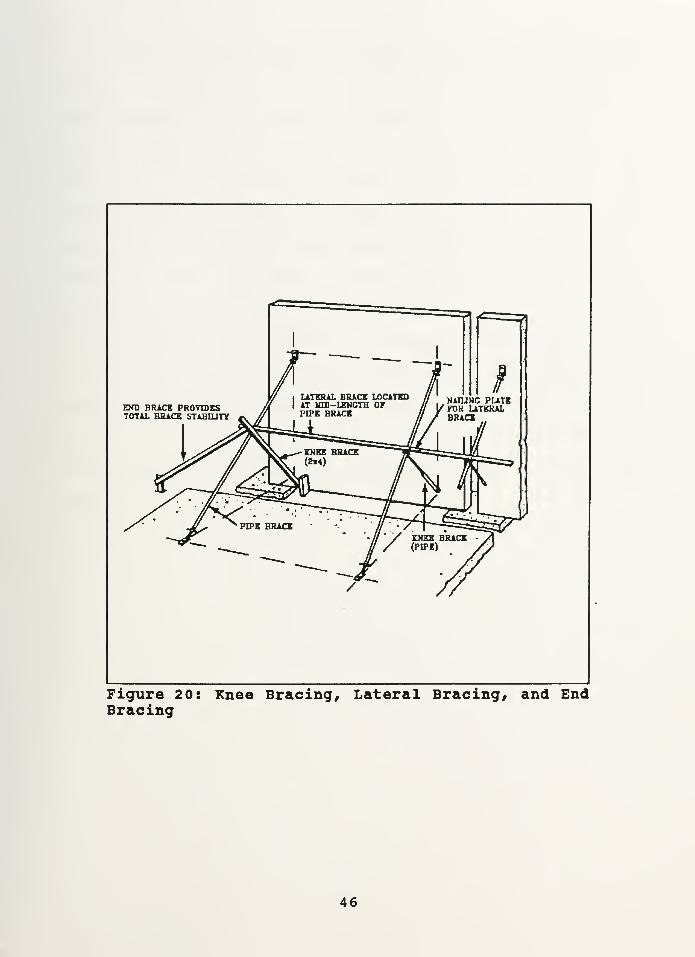
END BRICK PROVIDESTOTAL BRACE STABILITY
Figure 20: Knee Bracing, Lateral Bracing, and EndBracing
46


Temporary braces must be attached to the panel above the
center of mass to be effective against any overturning forces.
The temporary braces should be securely fastened to the floor
slab and the wall before the crane rigging is released from
the panel. If the crane rigging is released too soon, the
panel could fall over and cause significant damage and
personal injury. As a common practice, all brace connections
should be kept a minimum of one foot from any panel edge,
opening, control joint or construction joint to prevent
failure of the brace connection. To ensure lateral stability,
at least two temporary braces should always be used on each
panel. When knee braces are required, the knee must be
located at the middle point of the main brace, and the
accompanying lateral bracing must be located at this same
spot.
47


CHAPTER SEVENCONNECTIONS FOR TILT-UP CONSTRUCTION
7. 1 Design Considerations
One of the most important design features of a tilt-up
structure is the connections for the foundation, the
connections between individual panels, and connections for the
roof. The connections are determined by the design engineer,
and they are determined based on "strength, ductility,
durability, and economy" (5:1). In addition to these four
design requirements, fabrication methods and construction time
need to be considered. Designs that fail to recognize the
importance of connection details on the overall erection plan
can cause substantial delays during construction. Usually,
the best connection designs are the simplest ones. "By
reducing the number of components for a connection,
construction economy and efficiency can be enhanced" (5:4).
Whenever possible, connections should be optimized to reduce
the number of different types of connections. For example, if
one connection requires No. 3 reinforcing bar and No. 4 bar
is required for another connection, it may be more economical
to use No. 4 reinforcing bar on both connections. Anytime the
number of different details can be reduced, a savings can be
recognized during the construction. Whenever possible, the
smallest reinforcing bar size allowable should be chosen to
help reduce congestion in the connections. During
construction, when embedded structural steel and threaded
48


inserts are misaligned, delays to construction are inevitable,
so it is extremely important to not only ensure good designs
but to also ensure good construction practices.
7.2 Types of Connections
Tilt-up panels must not only serve as a building's
external cladding, but they must also carry vertical and
horizontal loads. To ensure a tilt-up buildings panels can
adeguately carry the imposed loads, the panels must be
adequately designed to transfer the forces from the roof and
floor members into the foundations. Also, connections must
have ductility to relieve temperature and shrinkage stresses,
to relieve seismic stresses, and to minimize cosmetic
cracking. Tilt-up connections can be categorized into four
main groups: cast-in-place, welded embedded metal, embedded
inserts, and drilled-in inserts.
"Cast-in-place connections are made by casting infill
sections between the erected panel components with overlapping
rebar projecting from the ends of the panel" (3:11) . Cast-in-
place connections are very strong, but they can be expensive.
Since cast-in-place connections are very rigid, the designer
must ensure proper attention is given to temperature and
shrinkage stress buildup.
The most common type of tilt-up connections are welded
embedded metal connections. These connections are constructed
by using an anchored embedded steel plate or angle cast
49


directly into the tilt-up panel, and the exposed surfaces of
adjoining elements are field welded. The advantage of the
welded embedded metal connections are they are strong enough
for most applications, they are fast and inexpensive, and they
are fairly ductile.
Embedded inserts and drilled-in inserts allow adjoining
elements to be bolted together. Embedded inserts are simply
ferrule loops cast into the tilt-up panels, and drilled-in
inserts are usually expansion anchors. Both the ferrule loops
and the expansion anchors allow bolted connections to be made
directly. The advantages of both of these bolted connections
are they eliminate the requirement for field welding, and the
drilled-in inserts can be used to conveniently correct any
slight errors in alignments. Embedded inserts and bolted
connections "are the cheapest but least reliable
[connections]" (3:12). It is important to note that bolted
connections should only be used for connecting nonstructural
elements, and they should not be used in buildings subject to
seismic loading due to their poor performance under cyclic
loading.
7. 3 Foundation Connections
There are many variations for tilt-up panel foundations
and connections. For panel foundations, it is important to
provide connections between the tilt-up panels, the building
foundation, and the floor slab. Without connections at the
50

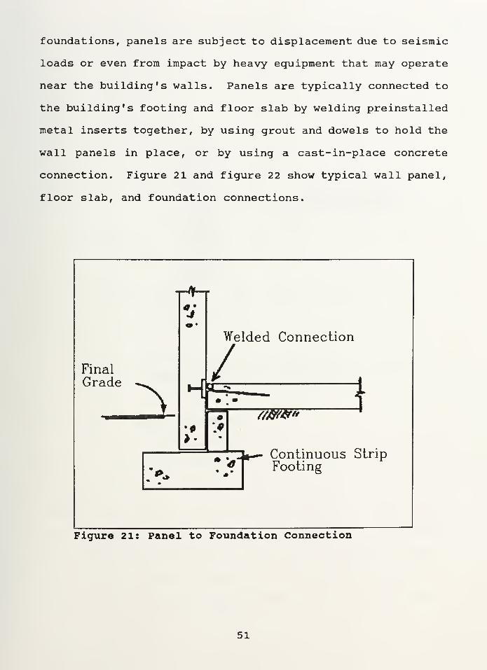
foundations, panels are subject to displacement due to seismic
loads or even from impact by heavy equipment that may operate
near the building's walls. Panels are typically connected to
the building's footing and floor slab by welding preinstalled
metal inserts together, by using grout and dowels to hold the
wall panels in place, or by using a cast-in-place concrete
connection. Figure 21 and figure 22 show typical wall panel,
floor slab, and foundation connections.
FinalGrade ^
t»
Welded Connection
*
:**
//&#"
Continuous StripFooting
Figure 21: Panel to Foundation Connection
51


Slab Infill
/F loor Slab
SB<
1 :::::::::: :!>1 .--
Final Grade Welded Rebar
Figure 22: Panel to Foundation Connection
7 . 4 Panel to Panel Connections
Panel to panel connections must be able to withstand
seismic loads and temperature expansion and contraction. The
most common panel to panel connections are made from welding
together embedded metal inserts in both panels. These welded
connections are fast and inexpensive, and they can be designed
with enough ductility to allow for seismic and thermal loads.
Cast-in-place concrete connections between panels can be used;
however their rigidity, high expense, and intensive labor
52


requirements make cast-in-place connections less popular today
than they were in earlier tilt-up buildings. The one
exception to this is corner connections; these are still often
done using cast-in-place columns to connect adjacent corner
slabs. Figure 23 shows both a rigid and nonrigid cast-in-
place concrete connection, and Figure 24 shows typical welded
panel to panel connections.
Cast in PlaceColumn
Non • rig id Connection
f
\rPanel
B\
\
/Rigid connection
Panel
ki 5Felt Strip Rebar
Figure 23: Rigid and Nonrigid Connections
53


:
NWELD
CONNECTION WITH SUITED PIPEWELDED TO EMBEDDMENTS
PLATE WELDED TOEMBEDDED ANGLES
Figure 24: Welded Panel-Panel Connections
7 . 5 Roof and Floor Connections
There are many ways to detail the connections between
tilt-up panels and the upper floors (in a multi-story
building) and the roof. The first consideration is going to
be the required loading, but another consideration is ease of
construction. Two common roof connections are shown is
figures 25 and 2 6 on the following pages. Both of these
systems are used for connecting open web joists to tilt-up
panels. In figure 25 a pocket is recessed in the panel, and
54


the steel joist is field welded or bolted to the seat. In
figure 26, the angle seat is welded to the embedded steel
plate, and the steel joist is then welded onto the angle seat.
Once the steel joists are attached to the erected panel, a
roof system can be installed. One important similarity
between both details shown in figures 2 5 and 2 6 is there are
no projections above the face of the panel. Using panels with
no projections allows for easy screediing and finishing and
allows for stack casting panels.
Rebar Ties
Welded to
Angle Seat
Joist Pocket Formedw/Polystyrene Block
Continuous Chord AngleWelded to Joist
\
Angle Seat w/Joist
Connected by Field
Weld or Bolts
Figure 25: Recessed Floor/Roof Connection
55

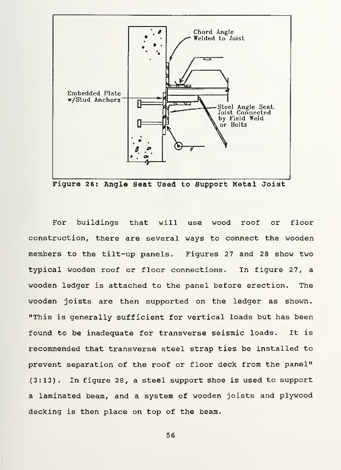
Chord AngleWelded to Joist
Embedded Platew/Stud Anchors
Steel Angle Seat.Joist Connectedby Field Weldor Bolts
Figure 26: Angle Seat Used to Support Metal Joist
For buildings that will use wood roof or floor
construction, there are several ways to connect the wooden
members to the tilt-up panels. Figures 27 and 28 show two
typical wooden roof or floor connections. In figure 27, a
wooden ledger is attached to the panel before erection. The
wooden joists are then supported on the ledger as shown.
"This is generally sufficient for vertical loads but has been
found to be inadequate for transverse seismic loads. It is
recommended that transverse steel strap ties be installed to
prevent separation of the roof or floor deck from the panel"
(3:13). In figure 28, a steel support shoe is used to support
a laminated beam, and a system of wooden joists and plywood
decking is then place on top of the beam.
56


Strap TieNailed ThrouglPly Deck &into Joist
* 9
ft. ft
Plywood
f Decking
Blocking
Wood Ledger
Figure 27: Wood Joist Supported on Wood Ledger
57


PlywoodDecking
Steel Support Shoe
Figure 28: Wood Beam Supported in Steel Shoe
58


For buildings designed to sustain substantial floor
loads, stronger connections are required than the connections
previously discussed. For buildings that will have the heavy
floor loads carried on steel beams, a connection as shown in
figure 29 on the following page is required. In this
connection, a full height pilaster can be used to support
heavy beam loads. As an option, a smaller concrete corbel or
a welded steel angle seat can be used where loading allows.
In figure 29, note the importance of using ties to keep the
edge of the pilaster from failing due to shear. Figure 30 on
the following page shows a connection similar the wood ledger
system of figure 27 except the connection in figure 3 uses a
concrete ledger to support a precast double tee concrete beam.
When a concrete ledger is used to support a concrete beam, the
beam should rest on a neoprene pad as shown to allow for some
rotational movement of the beam. Also, the beam should be
tied in at the top. The main disadvantage of the systems
shown in figures 29 and 3 is they both have protrusions which
make forming and casting the panels much more difficult. For
figure 30, the embedded rebar used to tie in the top of the
precast beam can get in the way during the placement of the
beam, so extra care (and more time) is required when using
this system.
59


Wall PanelReinforcing
Rebar TiesWelded to
Angle Seat
Closed Ties _^^*~*Around Bolls
Chord Angle
Shear PlaneLine of Failure
Figure 29: Steel Beam on Pillaster
60


Reinforced ConcreteTopping
Precast Beam(Double Tee)
Figure 30: Double Tee on Concrete Ledger
61


CHAPTER EIGHTCONCLUSION
"With Adequate planning and proper procedures, tilt-up
can be an efficient, safe method of erecting structural
concrete walls quickly with a minimum of labor and formwork"
(3:27). The key to tilt-up's economy is to effectively
coordinate the work to avoid delays by maximizing the use of
crane time to speed up the job. Tilt-up construction's
natural economy, versatility, and availability of advanced
architectural treatments give tilt-up the potential to grow
and command a larger share of the total building construction
market.
62


REFERENCES
1. Portland Cement Association, Tilt-up Concrete Buildings .
Skokie, IL, 1989.
2. Dayton Superior Corporation, Tilt-up ConstructionHandbook . Miamisburg, OH, 1990.
3. American Concrete Institute, Tilt-up Construction,ACI Compilation No. 7 . Detroit, MI, 1986.
4. The Burke Company, Burke on Tilt-up . Buffalo, NY,1988.
5. Portland Cement Association, Connections for Tilt-upWall Construction . Skokie, IL, 1987.
63


BIBLIOGRAPHY
American Concrete Institute, Tilt-up Construction, ACICompilation No. 7 . Detroit, MI, 1986.
Dayton Superior Corporation, Tilt-up Construction Handbook .
Miamisburg, OH, 1990.
Hurd, M.K., "The Many Faces of Tilt-up, From Plain Surfaces toWorks of Art", Concrete Construction . September, 1987.
Hurd, M.K., "The Tilt-up Opportunity", Concrete Construction .
September 1987.
Portland Cement Association, Connections for Tilt-up WallConstruction . Skokie, IL, 1987.
Portland Cement Association, Tilt-up Concrete Buildings .
Skokie, IL, 1989.
Portland Cement Association, Tilt-up Load Bearing Walls,
Skokie, IL, 1979.
Richmond Screw Anchor Company, Products for Tilt-up ConcreteConstruction . Fort Worth, TX, 1980.
Schierloh, David, M. , "Tilt-up: A Feat of Engineering", Tilt-up . Fall, 1991, pp. 6-7.
The Burke Company, Burke on Tilt-up . Buffalo, NY, 1988.
64


C87473Ctowt^ consttuction.
C .1
Thesis
C8:473 Cromptonc.l Tilt-up construction.
