tillage max chisel - greatplainsag.com...tillage max chisel proper servicing and adjustment is key...
TRANSCRIPT

FIELD ADJUSTMENT GUIDE
Document #TLUS410C-0001B1 of 5
Document # TLUS410C-0001B
Tillage
Max Chisel
Proper servicing and adjustment is key to the long life of all farm equipment. With careful and systematic inspection of equipment, costly maintenance, time and repair can be avoided. The following information will assist with recommended servicing and adjustments:
49038
Models Affected:MC5109, MC5111, MC5313, MC5315, MC5317, MC5319
Date: June 7, 2018
General Information
Document #TLUS410C-0001B 2 of 5
Hydraulic Hose Hookup:
Ensure that the tractor horsepower meets the mini-mum requirement for the implement being pulled. This is important so that the implement can work as effi-ciently as possible.
1) Connect the Max Chisel to the tractor using a lock-ing style pin. Ensure that the safety lights and chain are hooked up.
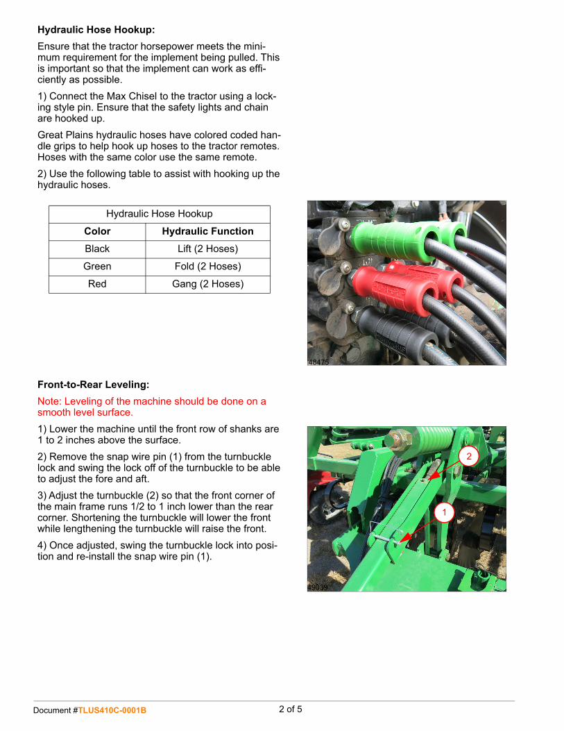
Great Plains hydraulic hoses have colored coded han-dle grips to help hook up hoses to the tractor remotes. Hoses with the same color use the same remote.
2) Use the following table to assist with hooking up the hydraulic hoses.
48475
Hydraulic Hose Hookup
Color Hydraulic Function
Black Lift (2 Hoses)
Green Fold (2 Hoses)
Red Gang (2 Hoses)
49039
1
2
Front-to-Rear Leveling:
Note: Leveling of the machine should be done on a smooth level surface.
1) Lower the machine until the front row of shanks are 1 to 2 inches above the surface.
2) Remove the snap wire pin (1) from the turnbuckle lock and swing the lock off of the turnbuckle to be able to adjust the fore and aft.
3) Adjust the turnbuckle (2) so that the front corner of the main frame runs 1/2 to 1 inch lower than the rear corner. Shortening the turnbuckle will lower the front while lengthening the turnbuckle will raise the front.
4) Once adjusted, swing the turnbuckle lock into posi-tion and re-install the snap wire pin (1).

Document #TLUS410C-0001B3 of 5
49040
3
Wing Adjustments (Models 5313-5315):
Note: The machine must be leveled front-to-rear before the wings can be properly adjusted.
1) Unfold the machine onto a level surface and com-pletely extend the wing fold cylinders.
2) If the machine does not appear to be level, fold the wings back up and install shims as needed to level the wings. Note: Extra shims are stored in the manual pack. The extra shims may be needed in the future if the hinge holes or bolts begin to wear. If there are two different thickness of shims, multiple shims may be used to level the wings.
3) Remove the two bolts (3) holding the shims in place and either add more shims to raise the wings or remove shims to lower the wings.
4) Once the desired shims have been installed or removed, re-install the previously removed bolts and tighten to spec.
49041
6
Depth Stop Adjustment:
Once the machine is level, the depth stop can be set to ensure consistent depth on every pass.
1) Screw the depth stop handle (6) out all the way so that no threads show in front of the bracket.
2) Screw the handle back in 24 revolutions to set the working depth at approximately 9”.
After setting the depth stop, if a change of depth is desired, 1 full turn of the adjustment handle either in or out will change the depth of the machine approxi-mately 1/4 inch up or down.
4947949479
4
5
Wing Adjustment (Models 5317-5319):
Note: The machine must be leveled front to rear before the wings can be properly adjusted.
1) Unfold the machine onto a level surface and com-pletely extended the wing fold cylinders.
2) Lower the machine until the shanks are 1-2” off of the ground.
3) Loosen the jam nuts (4), and adjust the wing turn-buckles (5) (shortening the turnbuckles raise the wings and extending the turnbuckles lowers the wings) to match the center frame.
4) Once the machines is leveled side to side, re-tighten the jam nuts.

Document #TLUS410C-0001B 4 of 5
49044
Gang Frame Adjustment:
Once the machine has been leveled front to back and side to side, the gang frame can then be adjusted.
Note: Do not run the blades deeper than 5 inches. 3-4 inches is the optimum operating depth.
1) Initially set the blade depth gauge to “C”. At this position the blades should be running at 4 inches. Refer to the following table for proper gang adjustment as the shank depth varies.
Settings for 4” Disk Blade Depth
Shank Depth Inches Gauge Setting
6 A
7 1/2 B
9 C
10 1/2 D
12 E
Chopper Reel Arm Adjustment:
Note: Chopper reel mounting tubes are shipped in the completely collapsed position. Adjust the mounting tubes prior to using the machine.
1) Loosen and remove the bolts retaining the inner chopper mounting tube. Slide the inner tube out until the 24.5” dimension (show in the illustration) is achieved or until the holes align in position (7). Re-insert the bolts through both tubes (7).
Chopper Reel Eyebolt Adjustment:
The chopper reel eyebolt must be adjusted so that the pin (8) consistently runs in the middle of the slot.
1) In order to adjust the eyebolt so that the pin is in the middle, loosen the jam nuts (9).
2) Adjust the eyebolt either in or out until the pin is centered in the slot. Once adjusted, re-tighten the jam nuts.
49042
9
7
8
24.5”

Document #TLUS410C-0001B5 of 5
Chopper/ML Roller Adjustment (Option):
Choppers are adjustable for more or less severe down pressure for chopping residue and pulling dirt back into the shank voids.
For less down pressure set the spring eye bolt (10) in hole #1 and for more down pressure set the spring in hole #4.
Recommended chopper settings:
Shank Depth: 7-9”
Chopper Spring Setting: Hole #1
Shank Depth: 8-10”
Chopper Spring Setting: Hole #2
Shank Depth: 9-11”
Chopper Spring Setting: Hole #3
Shank Depth: 10-12”
Chopper Spring Setting: Hole #4
49448
10
Hydraulic Roller Adjustment:
The roller is controlled by active hydraulic down pres-sure (11) that is controlled by a valve located on the hitch of the machine. It is recommended that the roller down pressure be set between 300-500 psi.
Depending on the soil conditions, the roller can also be ran effectively in float. Note: If the roller is not being ran with live hydraulics it must be in the FLOAT posi-tion. Failure to operate in either float or active down pressure may damage the system.
The rollers can also be temporarily lifted off the ground with the roller arms (12) if necessary. It is not recom-mended to run this way for an extended period of time to avoid damaging the cylinders. 49449
11
12