tia-942 data center standards overview -...
TRANSCRIPT
TIA-942 Data Center Standards Overview
0::: w a... ~ w l-I
5:
••
B.
TIA-942 Data Center Standards Overview
For the past 20 years, cabling standards have been the cornerstone of
ensuring proper design, installation, and performance of the network. The
Telecommunications Industry Association (TIA) revolutionized our industry when
they released the first TIA-568 Commercial Building Telecommunications Wiring
Standard, which describes the design, installation, and performance requirements
for telecommunications cabling systems in commercial buildings. On the whole,
standards have enabled our industry to effectively advance faster and further.
Unfortunately, data centers were historically designed in the absence of established
standards. This had many network administrators faced with the challenge of
choosing technologies and deciphering how to properly implement them into an
often-undersized space that is responsible for securely and reliably providing all the
existing and future services to an enterprise.
In April 2005, the TIA responded with the TIA-942 Telecommunications
Infrastructure Standards for Data Centers, the first standard to specifically address
data center infrastructure. Intended for use by data center designers early in the
building development process, TIA-942 covers the following:
• Site space and layout
• Cabling infrastructure
• Tiered reliability
• Environmental considerations
This paper describes the key elements of the TIA-942 standard, a valuable tool in
designing your data center and maximizing your investment.
TIA-942 Data Center Standards Overview
Site Space and Layout Proper space allocation for a data center starts with ensuring that space can be easily reallocated to changing environments and growth. Designers must strike a balance between acceptable initial deployment costs and anticipated space required in the future.
The data center should be designed with plenty of flexible "white space," empty space that can accommodate future racks or cabinets. The space surrounding the data center must also be considered for future growth and planned for easy annexation.
A large part of TIA-942 deals with facility specifications. The standard recommends specific functional areas, which helps to define equipment placement based on the standard hierarchical star topology design for regular commercial spaces. Designing a data center with these functional areas anticipates growth and helps create an environment where applications and servers can be added and upgraded with minimal downtime and disruption. According to TIA-942, a data center should include the following key functional areas:
One or More Entrance Rooms
This is the location for access provider equipment and demarcation points, as well as the interface with campus cabling systems. The Entrance Room may be located either inside or outside the computer room, the portion of the data center that houses data processing equipment. The standard recommends locating the entrance room outside of the computer room for better security. When located within the computer room, the Entrance Room should be consolidated with the MDA. It is possible that provider's cabling distances may require multiple Entrance Rooms for larger data centers.
Main Distribution Area (MDA)
Similar to an MDF, the MDA is a centrally located area that houses the main cross-connect as well as core routers and switches for LAN and SAN infrastructures. The MDA may include a horizontal cross-connect (HC) for a nearby equipment distribution area. The standard requires at least one MDA and specifies installing separate racks for fiber, UTP, and coaxial cable in this location.
Page 3
One or More Horizontal Distribution Areas (HDA)
Similar to a TR, the HDA serves as the distribution point for horizontal cabling and houses cross-connects and active equipment for distributing cable to the equipment distribution area. Like the MDA, the standard specifies installing separate racks for fiber, UTP, and coaxial cable in this location. It also recommends locating switches and patch panels to minimize patch cord lengths and facilitate cable management. The HDA is limited to 2000 connections, and the number of HDAs is dependent on the amount of cabling and overall size of the data center.
Equipment Distribution Area (EDA)
Horizontal cables are typically terminated with patch panels in the EDA, the location of equipment cabinets and racks. The standard specifies installing racks and cabinets in an alternating pattern to create" hot" and "cold" aisles, a configuration that effectively dissipates heat from electronics (see Environmental Considerations for a discussion on cooling and hot aisle/cold aisle configuration).
Zone Distribution Area (ZDA)
The ZDA is an optional interconnection point in the horizontal cabling between the HDA and EDA. The ZDA can act as a consolidation point for reconfiguration flexibility or for housing freestanding equipment like mainframes and servers that cannot accept patch panels. Only one ZDA is allowed within a horizontal cabling run with a maximum of 288 connections. The ZDA cannot contain any cross-connects or active equipment.
Backbone and Horizontal Cabling
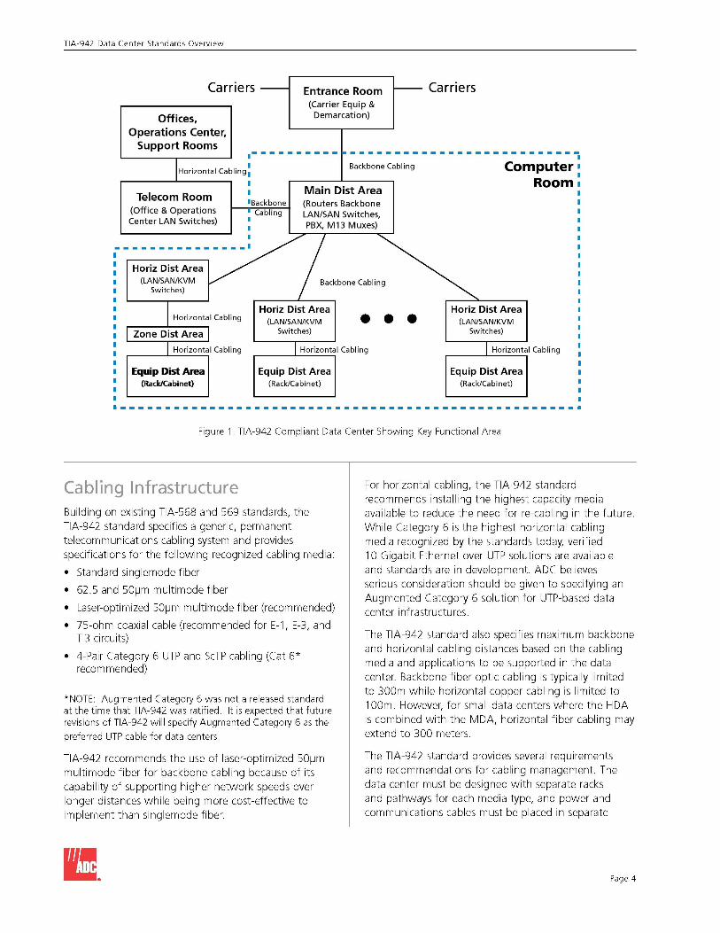
Within the data center, backbone cabling provides connections between MDA, HDAs, and Entrance Rooms while horizontal cabling provides connections between HDAs, ZDA, and EDA. Optional backbone cabling can be installed between HDAs for redundancy. Each functional area must be located in such a way to prevent exceeding maximum cable lengths for both backbone and horizontal cabling.
II.
TIA-942 Data Center Standards Overview
Carriers - Entrance Room r--- Carriers (Carrier Equip &
Offices, Demarcation)
Operations Center, Support Rooms
~ --------------------,- - - - - - - - - -IHorizontal Ca bling:
Backbone Cabling Co ,
Telecom Room , Main Dist Area
mputer Room
' Backbone (Routers Backbone (Office & Operations Center LAN Switches)
• Cabling , LAN/SAN Switches, , PBX, M13 Muxes)
--------------' Horiz Dist Area V j . (LAN/SAN/KVM Backbone Cabling
Switches)
I Horizontal Cabling Horiz Dist Area Horiz Dist Area
(LAN/SAN/KVM • • • (LAN/SAN/KVM
Zone Dist Area Switches) Switches)
I Horizontal Cabling I Horizontal Cabling I Hori zontal Cabling
Equip Dist Area Equip Dist Area Equip Dist Area (Rack/Cabinet) (Rack/Cabinet ) (Rack/Cabinet )
Figure 1. TIA-942 Compliant Data Center Showing Key Functional Area
Cabling Infrastructure Building on existing TIA-S68 and S69 standards, the TIA-942 standard specifies a generic, permanent telecommunications cabling system and provides specifications for the following recognized cabling media:
• Standard singlemode fiber
• 62.S and SOfJm multimode fiber
• Laser-optimized SOfJm multimode fiber (recommended)
• 7S-ohm coaxial cable (recommended for E-1, E-3, and T-3 circuits)
• 4-Pair Category 6 UTP and ScTP cabling (Cat 6* recommended)
*NOTE: Augmented Category 6 was not a released standard at the time that TIA-942 was ratified. It is expected that future
revisions of TIA-942 will specify Augmented Category 6 as the
preferred UTP cable for data centers.
TIA-942 recommends the use of laser-optimized SOfJm multimode fiber for backbone cabling because of its capability of supporting higher network speeds over longer distances while being more cost-effective to implement than singlemode fiber.
B.
For horizontal cabling, the TIA-942 standard recommends installing the highest capacity media available to reduce the need for re-cabling in the future. While Category 6 is the highest horizontal cabling media recognized by the standards today, verified 10 Gigabit Ethernet over UTP solutions are available and standards are in development. ADC believes serious consideration should be given to specifying an Augmented Category 6 solution for UTP-based data center infrastructures.
The TIA-942 standard also specifies maximum backbone and horizontal cabling distances based on the cabling media and applications to be supported in the data center. Backbone fiber optic cabling is typically limited to 300m while horizontal copper cabling is limited to 100m. However, for small data centers where the HDA is combined with the MDA, horizontal fiber cabling may extend to 300 meters.
The TIA-942 standard provides several requirements and recommendations for cabling management. The data center must be designed with separate racks and pathways for each media type, and power and communications cables must be placed in separate
Page 4
TIA-942 Data Center Standards Overview
pathways or separated by a physical barrier. Adequate space must be provided within and between racks and cabinets and in pathways for better cable management, bend radius protection, and access. For example, the standard requires a minimum of 3 feet in rows (4 feet recommended) and recommends aligning racks and cabinets on raised floors in a way that enables easy lifting of tiles. Locating switches and patch panels to reduce the need for patching between cabinets and racks is also recommended.
TIA-942 extends the TIA-606-A Administration Standard to data centers, which specifies a labeling scheme for all racks, cabinets, patch panels, patch cords, and cables.
Tiered Reliability To provide a means for determining specific data center needs, the TIA-942 standard includes an informative annex with data center availability tiers. These tiers are based on information from the Uptime Institute, a consortium dedicated to providing its members with best practices and benchmark comparisons for improving the design and management of data centers.
For each of the four tiers, the annex describes detailed architectural, security, electrical, mechanical, and telecommunications recommendations, and the higher the tier, the higher the availability. Tier descriptions include information like raised floor heights, watts per square foot, and points of failure. "Need," or "N," indicates the level of redundant components for each tier with N representing only the necessary system need. Construction cost per square foot is also provided and varies greatly from tier to tier; with Tier 3 costs double that of Tier 1 .
Breaking data center reliability into these tiers provides designers with a method for qualifying certain aspects of the data center and objectively comparing one data center to another.
Tier 1- Basic: 99.671% Availability
• Susceptible to disruptions from both planned and unplanned activity
• Single path for power and cooling distribution, no redundant components (N)
• Mayor may not have a raised floor, UPS, or generator
• Takes 3 months to implement
• Annual downtime of 28.8 hours
• Must be shut down completely for perform preventive maintenance
Page 5
Tier 2 - Redundant Components: 99.741% Availability
• Less susceptible to disruption from both planned and unplanned activity
• Single path for power and cooling disruption, includes redundant components (N+ 1)
• Includes raised floor, UPS, and generator
• Takes 3 to 6 months to implement
• Annual downtime of 22.0 hours
• Maintenance of power path and other parts of the infrastructure require a processing shutdown
Tier 3 - Concurrently Maintainable: 99.982% Availability
• Enables planned activity without disrupting computer hardware operation, but unplanned events will still cause disruption
• Multiple power and cooling distribution paths but with only one path active, includes redundant components (N+1)
• Takes 15 to 20 months to implement
• Annual downtime of 1.6 hours
• Includes raised floor and sufficient capacity and distribution to carry load on one path while performing maintenance on the other.
Tier 4 - Fault Tolerant: 99.995% Availability
• Planned activity does not disrupt critical load and data center can sustain at least one worst-case unplanned event with no critical load impact
• Multiple active power and cooling distribution paths, includes redundant components (2 (N+1), i.e. 2 UPS each with N+ 1 redundancy)
• Takes 15 to 20 months to implement
• Annual downtime of 0.4 hours
Environmental Considerations Several environmental considerations exist within the TIA-942 data center standard that are similar to the equipment room requirements set forth in previous TIA standards. These considerations include, but are not limited to, fire suppression, humidity levels, operating temperatures, architectural, electrical (power) and mechanical system specifications. Some of the requirements are dependent on the desired reliability tier described above.
II.
TIA-942 Data Center Standards Overview
Power Determining power requirements is based on the desired reliability tier and may include two or more power feeds from the utility, UPS, multiple circuits to systems and equipment, and on-site generators. Determining power requirements requires careful upfront planning.
Estimating power needs involves determining the power required for all existing devices and for devices anticipated in the future. Power requirements must also be estimated for all support equipment such as UPS, generators, conditioning electronics, HVAC, lighting, etc. The power estimation must be made to accommodate required redundancy and future growth.
0; Q)
a::
Cabinets
Telecom Cable Trays
Tiles
Power Cables 00000
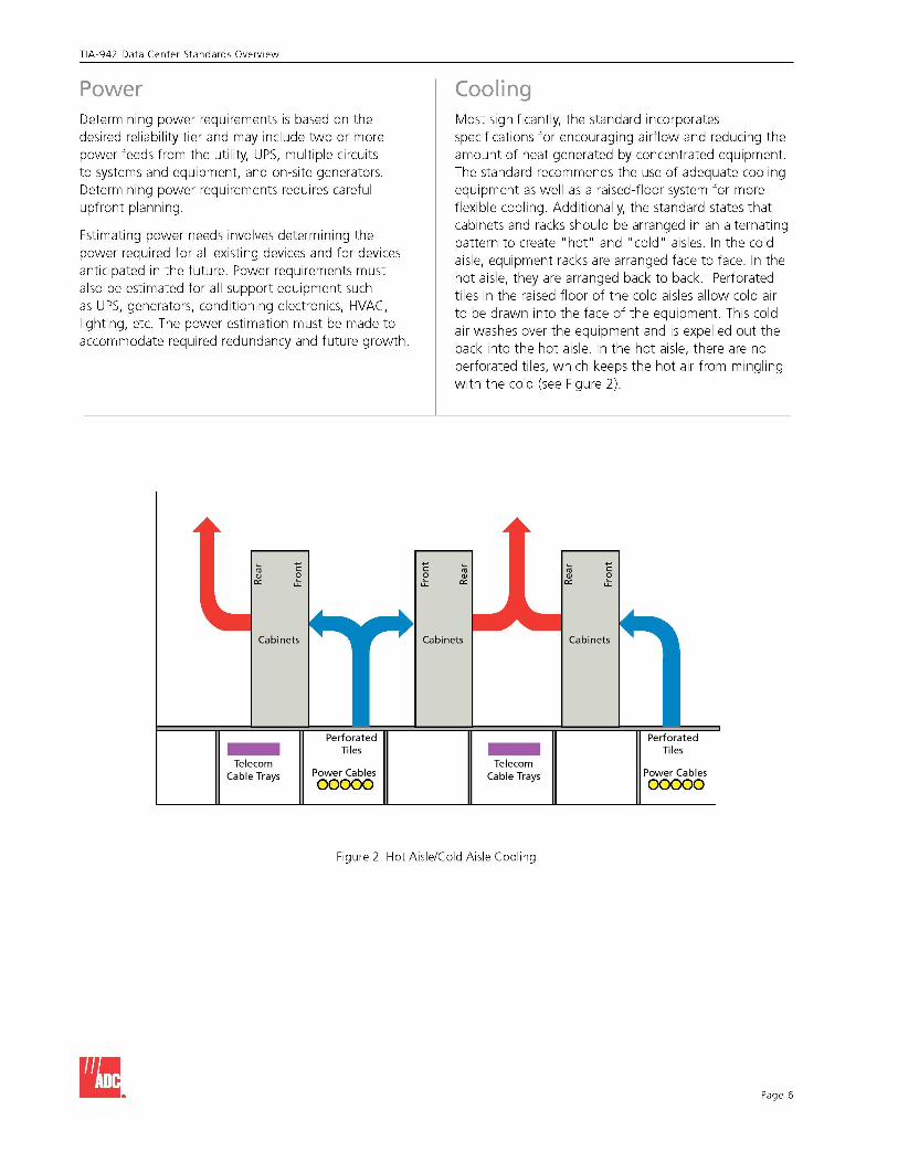
Cooling Most significantly, the standard incorporates specifications for encouraging airflow and reducing the amount of heat generated by concentrated equipment. The standard recommends the use of adequate cooling equipment as well as a raised-floor system for more flexible cooling. Additionally, the standard states that cabinets and racks should be arranged in an alternating pattern to create "hot" and "cold" aisles. In the cold aisle, equipment racks are arranged face to face. In the hot aisle, they are arranged back to back. Perforated tiles in the raised floor of the cold aisles allow cold air to be drawn into the face of the equipment. This cold air washes over the equipment and is expelled out the back into the hot aisle. In the hot aisle, there are no perforated tiles, which keeps the hot air from mingling with the cold (see Figure 2).
0; Q)
a::
Cabinets
Telecom Cable Trays
Cabinets
Tiles
Power Cables 00000
Figure 2. Hot Aisle/Cold Aisle Cooling
B. Page 6
TIA-942 Data Center Standards Overview
Because not every active piece of equipment exhausts heat out the back, other considerations for cooling include the following:
• Increase airflow by blocking unnecessary air escapes and/or increasing the height of the raised floor
• Spread equipment out over unused portions of the raised floor, space permitting
• Use open racks instead of cabinets when security is not a concern, or use cabinets with mesh fronts and backs
• Use perforated tiles with larger openings
Conclusion When it comes to building a reliable data center and maximizing your investment, the design must be considered early in the building development process and include coordinated efforts that cut across several areas of expertise including telecommunications, power, architectural, and HVAC.
Each of the components of the data center and its supporting systems must be planned, designed, and implemented to work together to ensure reliable access of data center resources while supporting future requirements. Neglecting any aspect of the design can render the data center vulnerable to cost failures, early obsolescence, and intolerable availability. There is no substitute for careful planning and following the guidelines set forth in the TIA-942 Telecommunications Infrastructure Standards for Data Centers.
Page 7
To obtain a copy of the TIA-942 standard or to receive more information, visit the following websites:
For Information on
TIA-942 Standard
Visit The TIA at:
wwwtiaonline.org/standards
For information on
General data center reliability information including power and cooling
Visit The Uptime Insistute at:
wwwupsite.com
For Information on
Components and Best Practices
Visit ADC at:
wwwadc.com
II.
0::: w a..
~ w l-I $
®
Web Site: www.adc.com From North America, Call Toll Free: 1-800-366-3891 • Outside of North America: + 1-952-938-8080
Fax: + 1-952-917-3237 • For a listing of ADC's global sales office locations, please refer to our web site.
ADC Telecommunications, Inc, PO Box 1101, Minneapolis, Minnesota USA 55440-1101 Specifications published here are current as of the date of publication of this document. Because we are continuously improving our products, ADC reserves the right to change specifications without prior notice. At any time, you may verify product specifications by contacting our headquarters office in Minneapolis. ADC Telecommunications, Inc views its patent portfolio as an important corporate asset and vigorously enforces its patents. Products orfeatures contained herein may be covered by one or more U.S. or foreign patents. An Equal Opportunity Employer
102264AE 1/06 Original © 2006 ADC Telecommunications, Inc. All Rights Reserved