ti mmwave sensors: get up and running · ti mmwave sensors: get up and running 1 industrial mmwave...
TRANSCRIPT

TI mmWave Sensors: Get Up and Running
1
Industrial mmWave Applications Team
4/3/2018

Agenda
2
• Introductions • Walk through OOB (out-of-box) Demo of SDK1p1
– Options in mmwave demo visualizer – Understanding configuration file options
• Feature highlights of Mmwave SDK1p1 OOB Demo • Demo of calibration feature/dataformat • QA

Introductions
3
4/3/2018

Presenters
4
Michelle Liu Application Engineer, Industrial mmWave Radar.
Currently works on Mmwave radar SOCs, focusing on application notes publication, customer support on Mmwave SDK and release of Mmwave training labs. Before that, she worked on the digital front end in small cell application.
Adrian Ozer Application Engineer, Industrial mmWave Radar
Bachelors at Texas A&M University, Masters at the University of Texas at San Antonio. Applications in analog logic before joining the Industrial Radar team.

About Out of box (OOB) demo
5
• Out-of-box demo with easy configurability via TI cloud based GUI
• The demonstration assumes that mmwave SDK has been installed and binaries are flashed
• IWR1443BOOST EVM will be used as an example for the OOB demo walkthrough

Walk Through of OOB Demo
6
4/3/2018
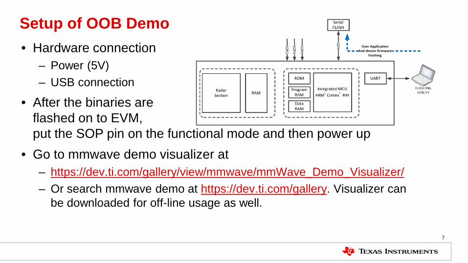
Setup of OOB Demo
7
• Hardware connection – Power (5V) – USB connection
• After the binaries are flashed on to EVM, put the SOP pin on the functional mode and then power up
• Go to mmwave demo visualizer at – https://dev.ti.com/gallery/view/mmwave/mmWave_Demo_Visualizer/ – Or search mmwave demo at https://dev.ti.com/gallery. Visualizer can
be downloaded for off-line usage as well.

Switch to Visualizer
8
4/3/2018

New Features of OOB Demo (SDK1.1)
9
4/3/2018

New Features and Demo
10
• Added support for advanced frame config in mmW demo for xWR16xx(will not show)
• Added Static clutter removal command – the mean value of the input samples to the 2D-FFT are subtracted (already demoed)
• Added new procedure and command in mmW demo to enable user to measure and compensate for range bias and rx antenna gain and phase error (will be demoed next)

Range Bias and Rx Channel Gain/Phase Measurement and Compensation
11
• Place a strong target at distance X (> 50cm) • Use the included profile_calibration.cfg, set command:
– measureRangeBiasAndRxChanPhase 1 X D – D is the distance of a few range bins
• Start the sensor with the configuration file
• The measurement results are written out on the CLI port
• The command printed out on the CLI now can be copied and pasted in any configuration file for correction purposes

Range Bias and Rx Channel Gain/Phase Measurement and Compensation
12
• The range bias and RX channel gain offset will compensate for the inherent offset due to signal chain processing delays and board delays
• The phase measurement offset compensates for the phase delay between receivers to give a linear phase response between receivers
• compRangeBiasAndRxChanPhase <rangeBias> <Re(0,0)> <Im(0,0)> <Re(0,1)> <Im(0,1)> ... <Re(0,R-1)> <Im(0,R-1)> <Re(1,0)> <Im(1,0)> ... <Re(T-1,R-1)> <Im(T-1,R-1)>

Useful Links
13
• Mmwave demo visualizer – https://dev.ti.com/gallery/view/mmwave/mmWave_Demo_Visualizer/ – Or search mmwave demo at https://dev.ti.com/gallery. Visualizer can
be downloaded for off-line usage as well. – Mmwave demo visualizer user guide
• Mmwave SDK: http://www.ti.com/tool/mmwave-sdk – SDK user guide is located under SDK_Install_DIR/docs
• Chirp design tool: Mmwave Sensing Estimator

Backups/Deleted
14

Demo in Visualizer (placeholder)
15
• Online Visualizer link (include download location), • help menu showing the user guide link, • show the uart ports • Reset EVM, will show in the console the EVM platform/SDK
version • Introduce the two tabs of visualizer

Mmwave Demo Visualizer (placeholder)
16
• Two tabs – Configure and Plots – Plots enables user to load existing configuration files – Configure provides more flexibility – Either case, the CLI commands are shown in the Configure tab
console messages, and all plots are in Plots tab • Configure Tab
– Scene Selection/Object Detection/Plot selection options – Configurations can be saved
• Plots Tab – X-Y scatter plot, 3D plot, Range Profile, Doppler-Range plots…. – Display parameters selection

The effect on configuration
17
• Antenna Config– corresponds to channelCfg setting (note, requires a reset of board for this change)
• Desirable Configuration – gives pre-optimized cfgs • Frequency Band – directly affect range resolution and profileCfg • Frame Rate – corresponds to the frameCfg parameter • The rest of Scene Selection gauges will affect the profileCfg
– Scene Selection/Object Detection/Plot selection options – Configurations can be saved
• Plot selection corresponds to guiMonitor command • Mention of clutterRemoval and cfarCfg (will demo later)

Plots tab
18
• Load cfg button • Sensor Start, will change to Sensor Stop when click • Talk about display parameters in following sequence:
– Chirp/frame – Scene – Profiling
Plots tab (cont)
19
• Talk about the X-Y plots and range plots. – Dots correlation – all for detected objects – Noise profile vs range profile – Dot location, moving object from left to right – Show the zoom-in/pan feature of the plots
• Doppler map, dots also corresponds to the object, doing a hand gesture showing positive value when moving away and vice versa
• Demonstrate Cfar threshold setting and clutter removal effect
Plots tab (cont)
20
• Select Range Azimuth Heat Map – Make sure to point the darkest point corresponds to the object – Change object angle
• Select Range Doppler Heat Map – Mention that two heat maps are not to be selected at the same
time due to UART speed limitation – Make sure to point the darkest point corresponds to the object – Do a hand gesture again to show how the doppler heat map
change

Common commands of xwr1443 and xwr1642
21
• dfeDataOutputMode • channelCfg • adcCfg • profileCfg • chirpCfg • frameCf • compRangeBiasAndRxChanPhase
Same as SDK1.0
Added in SDK1.1: for range bias and rx antenna gain/phase offset
Commands with Added parameters for xWR1642
22
• adcbufCfg • guiMonitor • cfarCfg • peakGrouping • calibDcRangeSig • ClutterRemoval • measureRangeBiasAndRxChanPhase:
• For xWR1443, the commands are the same as before.
• For xWR1642, one more parameter is added at beginning –
• using -1 for legacy mode • the intended subframe number in
advanced frame mode
Set of Complex value representing compensation for virtual Rx channel phase bias (12 for xWR1443 and 8 for xWR1642)