ti-innovator™ hubcommands
TRANSCRIPT

TI-Innovator™Hub Commands
Learn more about TI Technology through the online help at education.ti.com/eguide.

ii
Important InformationExcept as otherwise expressly stated in the License that accompanies a program, TexasInstruments makes no warranty, either express or implied, including but not limited toany implied warranties of merchantability and fitness for a particular purpose,regarding any programs or book materials and makes such materials available solelyon an "as-is" basis. In no event shall Texas Instruments be liable to anyone for special,collateral, incidental, or consequential damages in connection with or arising out of thepurchase or use of these materials, and the sole and exclusive liability of TexasInstruments, regardless of the form of action, shall not exceed the amount set forth inthe license for the program. Moreover, Texas Instruments shall not be liable for anyclaim of any kind whatsoever against the use of these materials by any other party.
Learning More with the TI-Innovator™ Technology eGuide
Parts of this document refer you to the TI-Innovator™ Technology eGuide for moredetails. The eGuide is a Web-based source of TI-Innovator™ information, including:
• Programming with the TI CE Family of Graphing Calculators andTI-Nspire™ Technology, including sample programs.
• Available I/O Modules and their commands.
• Available breadboard components and their commands.
• Available TI-RGB Array and its commands.
• Available TI-Innovator™ Rover and its commands.
• Link to update the TI-Innovator™ Sketch software.
• Free classroom activities for TI-Innovator™ Hub.
Apple®, Chrome®, Excel®, Google®, Firefox®, Internet Explorer®, Mac®, Microsoft®,Mozilla®, Safari®, and Windows® are registered trademarks of their respective owners.
QR Codeë is a registered trademark of DENSO WAVE INCORPORATED.
Select images were created with Fritzing.
© 2011 - 2021 Texas Instruments Incorporated.

Contents
TI-Innovator™ Hub Commands Version 1.5 1Understanding Syntax 1Last Menu Entry 1HUB Menus 2Send("SET... 3Send("READ... 3Settings... 4Wait 4Get( 5eval( 5Rover (RV)... 5Send("CONNECT-Output... 5Send("CONNECT-Input... 6Ports... 7Send("RANGE... 7Send("AVERAGE... 7Send("DISCONNECT-Output... 8Send("DISCONNECT-Input... 8MANAGE 9COLLECT 9Additional Supported Commands Not Found in the Hub Menu 10
SET 12LIGHT [TO] ON/OFF 13COLOR [TO] r g b [[BLINK|TOGGLE] frequency] [[TIME] seconds] 13SOUND [TO] frequency [[TIME] seconds] 14TEMPO keyword for SOUND/SPEAKER 14SOUND OFF/0 15LED i [TO] ON/OFF 15LED i [TO] 0-255 16RGB i [TO] r g b [[BLINK|TOGGLE] frequency] [[TIME] seconds] 16COLOR.RED i [TO] ON/OFF/UP/DOWN/value [[BLINK|TOGGLE] frequency] [[TIME]seconds] 17COLOR.GREEN i [TO] ON/OFF/UP/DOWN/value [[BLINK|TOGGLE] frequency][[TIME] seconds] 17COLOR.BLUE i [TO] ON/OFF/UP/DOWN/value [[BLINK|TOGGLE] frequency] [[TIME]seconds] 18SPEAKER i [TO] frequency [[TIME] seconds] 18TEMPO keyword for SOUND/SPEAKER 19POWER 19SERVO i [TO] position 20SERVO i [TO] STOP 20
iii
iv
SERVO i [TO] ZERO 21SERVO i [TO] [CW/CCW] speed [[TIME] seconds] 21ANALOG.OUT i [TO] 22ANALOG.OUT i OFF|STOP 22VIB.MOTOR i [TO] PWM 23VIB.MOTOR i [TO] OFF|STOP 23VIB.MOTOR i [TO] 0-255/UP/DOWN/ON/OFF [[BLINK|TOGGLE] freq] [[TIME]seconds] 24COLOR.RED [TO] r [[BLINK|TOGGLE] frequency] [[TIME] seconds] 24COLOR.GREEN [TO] g [[BLINK|TOGGLE] frequency] [[TIME] seconds] 25COLOR.BLUE [TO] b [[BLINK|TOGGLE] frequency] [[TIME] seconds] 25BUZZER i [TO] ON [TIME seconds] 26BUZZER i [TO] OFF 26RELAY i [TO] ON/OFF 27SQUAREWAVE i [TO] frequency [duty [[TIME] seconds]] 27SQUAREWAVE i OFF 28DIGITAL.OUT i [TO] ON/OFF/HIGH/LOW/[[BLINK|TOGGLE] frequency] [[TIME]seconds] 28DIGITAL.OUT i [TO] OUTPUT/CLOCK 29DIGITAL.IN i [TO] INPUT/PULLUP/PULLDOWN 29AVERAGING [TO] n 29BBPORT 31
READ 32BRIGHTNESS 32BRIGHTNESS AVERAGE 33BRIGHTNESS RANGE 33DHT i 34DHT i TEMPERATURE 35DHT i HUMIDITY 36RANGER i 36READ RANGER i TIME 37LIGHTLEVEL i 37LIGHTLEVEL i AVERAGE 38LIGHTLEVEL i RANGE 39TEMPERATURE i 39TEMPERATURE i AVERAGE 40TEMPERATURE i CALIBRATION 40MOISTURE i 41MOISTURE i AVERAGE 41MOISTURE i RANGE 42MAGNETIC 42VERNIER 43ANALOG.IN i 43

ANALOG.IN i AVERAGE 43ANALOG.IN i RANGE 44ANALOG.OUT i 44DIGITAL.IN i 45SWITCH i 45BUTTON i 46MOTION i 46POTENTIOMETER i 47POTENTIOMETER i AVERAGE 47POTENTIOMETER i RANGE 48THERMISTOR i 48THERMISTOR i AVERAGE 49THERMISTOR i CALIBRATION 49AVERAGING 50LOUDNESS i 50LOUDNESS i AVERAGE 51LOUDNESS i RANGE 51BBPORT 53TIMER 54
Settings 55Wait 55Wait 56
Get( 56Get( 57
eval( 58eval( 58
CONNECT-Output 60LED i [TO] OUT n/BB n 60RGB i / COLOR [TO] BB r BB g BB b 61SPEAKER i [TO] OUT n/BB n 61POWER 62SERVO.CONTINUOUS i [TO] BB 6 62ANALOG.OUT i [TO] OUT i/BB i 63VIB.MOTOR 63BUZZER i [TO] OUT n/BB n 64RELAY i [TO] OUT n/BB n 64SERVO i [TO] OUT 3 65SQUAREWAVE i [TO] OUT n/BB n 65DIGITAL.OUT i [TO] OUT n/BB n [[AS] OUTPUT] 66BBPORT 67DCMOTOR i [TO] OUT n/BB n 67LIGHT 68COLOR 68
v

vi
SOUND 69CONNECT-Input 70DHT i [TO] IN n 70RANGER i [TO] IN n 71LIGHTLEVEL i [TO] IN n/BB n 71TEMPERATURE i [TO] IN n/BB n 72MOISTURE i [TO] IN n/BB n 73MAGNETIC 74VERNIER 74ANALOG.IN i [TO] IN n/BB n 75DIGITAL.IN i [TO] IN n/BB n [[AS] INPUT|PULLUP|PULLDOWN] 75SWITCH i [TO] IN n/BB n 76BUTTON i [TO] IN n/BB n 76MOTION i [TO] IN n/BB n 77POTENTIOMETER i [TO] IN n/BB n 77THERMISTOR i [TO] IN n/BB n 78RGB 78LOUDNESS i [TO] IN n 79BBPORT 80BRIGHTNESS 80
Ports 81RANGE 82BRIGHTNESS minimum maximum 82LOUDNESS i minimum maximum 83LIGHTLEVEL i minimum maximum 83TEMPERATURE i minimum maximum 84POTENTIOMETER i minimum maximum 84MOISTURE i minimum maximum 85THERMISTOR i minimum maximum 85ANALOG.IN i minimum maximum 86
AVERAGE 87BRIGHTNESS n 88LOUDNESS i n 88LIGHTLEVEL i n 88TEMPERATURE i n 89POTENTIOMETER i n 89MOISTURE i n 90THERMISTOR i n 90ANALOG.IN i n 91PERIOD n 91
DISCONNECT-Output 92LED i 93RGB i 93

SPEAKER i 93POWER 94SERVO.CONTINUOUS i 94ANALOG.OUT i 95VIB.MOTOR 96BUZZER i 96RELAY i 96SERVO i 97SQUAREWAVE i 97DIGITAL.OUT i 98BBPORT 99LIGHT 99COLOR 99SOUND 100DCMOTOR i 100
DISCONNECT-Input 102DHT i 102RANGER i 103LIGHTLEVEL i 103TEMPERATURE i 104MOISTURE i 104MAGNETIC 105VERNIER 105ANALOG.IN i 106DIGITAL.IN i 106SWITCH 106BUTTON i 107MOTION i 107POTENTIOMETER i 108THERMISTOR i 108RGB 109LOUDNESS i 109BBPORT 110BRIGHTNESS 110
MANAGE 111BEGIN 111BEGIN 111
ISTI 112ISTI 112
WHO 112WHO 112
WHAT 113WHAT 113
vii

viii
HELP 113HELP 113
VERSION 114VERSION 114
ABOUT 114ABOUT 114
COLLECT 115COLLECT 115READ COLLECT 118
Additional Supported Commands 120Additional SET Commands 120FORMAT ERROR STRING/NUMBER 120FORMAT ERROR NOTE/QUIET 120FLOW [TO] ON/OFF 121OUT1/2/3 [TO] 122Additional READ Commands 123BUZZER i 123COLOR 123COLOR.RED 124COLOR.GREEN 124COLOR.BLUE 125DCMOTOR i 126DIGITAL.OUT i 126FORMAT 127FLOW 127IN1/IN2/IN3 128LAST ERROR 128LED i 129LIGHT 129OUT1/2/3 130PWR 130RELAY i 131RESOLUTION 131RGB i 131RED i 132GREEN i 133BLUE i 133SERVO i 134SERVO i CALIBRATION 134SOUND 135SPEAKER i 135SQUAREWAVE i 136Additional AVERAGE Commands 137

PERIOD n 137Additional CALIBRATION Commands 138CALIBRATE 138SERVO i / SERVO.CONTINUOUS i 138TEMPERATURE i C1 C2 C3 R1 139THERMISTOR i C1 C2 C3 R1 140
TI-Innovator™ Rover Commands Version 1.5 141Prerequisite: Use the Send "Connect RV" Command First 141Named RV Subsystems 141Rover Command Categories 142RV Commands, Code Samples, and Syntax 143
TI-Innovator™ Rover Menu 143Rover (RV)... 143
Drive RV... 148RV FORWARD 149RV BACKWARD 150RV LEFT 151RV RIGHT 151RV STOP 152RV RESUME 153RV STAY 153RV TO XY 154RV TO POLAR 154RV TO ANGLE 155
READ RV Sensors... 156RV.RANGER 156READ RV.RANGER TIME 157RV.COLORINPUT 157RV.COLORINPUT.RED 158RV.COLORINPUT.GREEN 159RV.COLORINPUT.BLUE 159RV.COLORINPUT.GRAY 160
RV Settings... 161Read RV Path… 162Reading WAYPOINT and PATH 162RV Position and Path 163RV.WAYPOINT.XYTHDRN 164RV.WAYPOINT.PREV 164RV.WAYPOINT.CMDNUM 165RV.PATHLIST.X 166RV.PATHLIST.Y 167RV.PATHLIST.TIME 167
ix

x
RV.PATHLIST.HEADING 168RV.PATHLIST.DISTANCE 168RV.PATHLIST.REVS 169RV.PATHLIST.CMDNUM 169RV.WAYPOINT.X 170RV.WAYPOINT.Y 171RV.WAYPOINT.TIME 171RV.WAYPOINT.HEADING 172RV.WAYPOINT.DISTANCE 172RV.WAYPOINT.REVS 173
RV Color… 174RV.COLOR 174RV.COLOR.RED 174RV.COLOR.GREEN 175RV.COLOR.BLUE 175
RV Setup… 177RV.POSITION 177RV.GYRO 177RV.GRID.ORIGIN 178RV.GRID.M/UNIT 178RV.PATH CLEAR 179RV MARK 179
RV Control… 181SET RV.MOTORS 181SET RV.MOTOR.L 182SET RV.MOTOR.R 182SET RV.ENCODERSGYRO 0 183READ RV.ENCODERSGYRO 183READ RV.GYRO 184READ RV.DONE 185READ RV.ETA 186
Send "CONNECT RV" 188CONNECT RV 188
Send "DISCONNECT RV" 189DISCONNECT RV 189
TI-RGB Array Commands 189Prerequisite: Use the Send "Connect RGB" Command First 189CONNECT RGB 190SET RGB 191SET RGB [n1 n2 n3…] r g b 191SET RGB PATTERN nnnn r g b 192SET RGB ALL 192

READ RGB 193
xi

TI-Innovator™ Hub Commands Version 1.5Use the Hub menus to create or edit a program. They can save you time buildingcommands and help you with correct command spelling and syntax.
When you see "Code Sample" in a command table, this "Code Sample" may be copiedand pasted as is to send to your graphing calculator to use in your calculations.
Example:
CodeSample:
Send("RV FORWARD")Send("RV FORWARD SPEED 0.2 M/S TIME 10")
Note: To build a command from the Hub menu, you need to know:
• The unique name of the component that you are addressing, such as "SOUND" forthe on-board speaker.
• The command parameters that apply to the component, such as sound frequencyand duration. Some parameters are optional, and you might need to know thevalue range of a parameter.
Understanding Syntax
• Capitalized words are keywords
• Lower case words are placeholders for numbers
• Commands within brackets are optional parameters
For example in: SET LIGHT ON [[BLINK|TOGGLE] frequency] [[TIME] seconds],"frequency" is entered as "1" and "seconds" is entered as "10".
Send("SET LIGHT 1 BLINK 2 TIME 10")
NOTE: The commands listed below are for CE Calculators. If you are using TI-Nspire™CX technology the parentheses are omitted. In addition, you will notice some otherminor differences in the commands such as "Endfor" instead of "End" with the TI-Nspire™ CX technology. Screenshots are provided for reference. Note: Actual menusmay vary slightly from provided images.
Last Menu Entry
Notice the last menu entries. These allow you to type in the name of the object insteadof selecting it from the menu. These can also be used for sensors and peripherals thatare not explicitly included in the menus. To use these, select the menu item to pastethe beginning of the command. You then type in the name of the sensor or device youare using.
TI-Innovator™ Hub Commands Version 1.5 1

2 TI-Innovator™ Hub Commands Version 1.5
Last Menu Entry CE Calculators TI-Nspire™ CX
– Send("SET
– Send("READ
– Send("CONNECT
– Send("DISCONNECT
HUB Menus
– Send("SET...– Send("READ...– Settings– Wait– Get(– eval(– Rover (RV)...– Send("CONNECT-Output...– Send("CONNECT-Input...– Ports...– Send("RANGE...– Send("AVERAGE...– Send("DISCONNECT-Output...– Send("DISCONNECT-Input...– Manage...– Collect...
CE Calculators TI-Nspire™ CX

Send("SET...
• SET– LIGHT– COLOR– SOUND– LED– RGB– SPEAKER– POWER– SERVO.CONTINOUS– ANALOG.OUT– VIB.MOTOR– COLOR.RED– COLOR.GREEN– COLOR.BLUE– BUZZER– RELAY– SERVO– SQUAREWAVE– DIGITAL.OUT– AVERAGING– BBPORT– Send("SET
CE Calculators TI-Nspire™ CX
Additional Set Commands
Send("READ...
• READ– BRIGHTNESS– DHT– RANGER– LIGHTLEVEL– TEMPERATURE– MOISTURE– MAGNETIC– VERNIER– ANALOG.IN
CE Calculators TI-Nspire™ CX
TI-Innovator™ Hub Commands Version 1.5 3

4 TI-Innovator™ Hub Commands Version 1.5
– DIGITAL.IN– SWITCH– BUTTON– MOTION– POTENTIOMETER– THERMISTOR– AVERAGING– RGB– LOUDNESS– BBPORT– TIMER– Send("READ
Additional READ Commands
Settings...
• Settings– ON– OFF– TO– TIME– BLINK– TEMPERATURE– HUMIDITY– CW– CCW– NAMED– PULLDOWN– INPUT– PH– FORCE10– FORCE50– PRESSURE– PRESSURE2
CE Calculators TI-Nspire™ CX
Wait CE Calculators TI-Nspire™ CX

• Wait
Get(
• Get(CE Calculators TI-Nspire™ CX
eval(
• eval(CE Calculators TI-Nspire™ CX
Rover (RV)...
– Drive RV…– Read RV Sensors…– RV Settings…– Read RV Path…– RV Color…– RV Setup…– RV Control…– Send "CONNECT RV"– Send "DISCONNECT RV"
CE Calculators TI-Nspire™ CX
Send("CONNECT-Output...
• CONNECT-Output– LED– RGB– SPEAKER– POWER
CE Calculators TI-Nspire™ CX
TI-Innovator™ Hub Commands Version 1.5 5

6 TI-Innovator™ Hub Commands Version 1.5
– SERVO.CONTINUOUS– DCMOTOR– ANALOG.OUT– VIB.MOTOR– BUZZER– RELAY– SERVO– SQUAREWAVE– DIGITAL.OUT– BBPORT– Send("CONNECT
– LIGHT– COLOR– SOUND
Send("CONNECT-Input...
• CONNECT-Input– DHT– RANGER– LIGHTLEVEL– TEMPERATURE– MOISTURE– MAGNETIC– VERNIER– ANALOG.IN– DIGITAL.IN– SWITCH– BUTTON– MOTION– POTENTIOMETER– THERMISTOR– RGB– LOUDNESS– BBPORT– Send("CONNECT
CE Calculators TI-Nspire™ CX

– BRIGHTNESS
Ports...
• Ports– OUT 1– OUT 2– OUT 3– IN 1– IN 2– IN: 3– I2C– BB 1– BB 2– BB 3– BB 4– BB 5– BB 6– BB 7– BB 8– BB 9– BB 10– BBPORT
CE Calculators TI-Nspire™ CX
Send("RANGE...
• RANGE– BRIGHTNESS– LOUDNESS– LIGHTLEVEL– TEMPERATURE– POTENTIOMETER– MOISTURE– THERMISTOR– ANALOG.IN
CE Calculators TI-Nspire™ CX
Send("AVERAGE... CE Calculators TI-Nspire™ CX
TI-Innovator™ Hub Commands Version 1.5 7
8 TI-Innovator™ Hub Commands Version 1.5
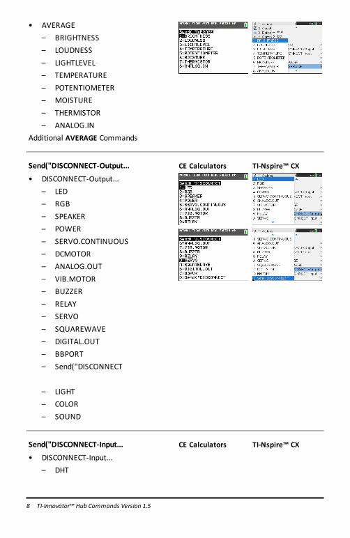
• AVERAGE– BRIGHTNESS– LOUDNESS– LIGHTLEVEL– TEMPERATURE– POTENTIOMETER– MOISTURE– THERMISTOR– ANALOG.IN
Additional AVERAGE Commands
Send("DISCONNECT-Output...
• DISCONNECT-Output...– LED– RGB– SPEAKER– POWER– SERVO.CONTINUOUS– DCMOTOR– ANALOG.OUT– VIB.MOTOR– BUZZER– RELAY– SERVO– SQUAREWAVE– DIGITAL.OUT– BBPORT– Send("DISCONNECT
– LIGHT– COLOR– SOUND
CE Calculators TI-Nspire™ CX
Send("DISCONNECT-Input...
• DISCONNECT-Input...– DHT
CE Calculators TI-Nspire™ CX

– RANGER– LIGHTLEVEL– TEMPERATURE– MOISTURE– MAGNETIC– VERNIER– ANALOG.IN– DIGITAL.IN– SWITCH– BUTTON– MOTION– POTENTIOMETER– THERMISTOR– RGB– LOUDNESS– BBPORT– Send("DISCONNECT
– BRIGHTNESS
MANAGE
• MANAGE– BEGIN– ISTI– WHO– WHAT– HELP– VERSION– ABOUT
CE Calculators TI-Nspire™ CX
COLLECT
• COLLECT– COLLECT– READ_COLLECT
CE Calculators TI-Nspire™ CX
TI-Innovator™ Hub Commands Version 1.5 9

10 TI-Innovator™ Hub Commands Version 1.5
Additional Supported Commands Not Found in the Hub Menu
• Additional SET Commands– FORMAT ERROR STRING/NUMBER– FORMAT ERROR NOTE/QUIET– FLOW [TO] ON/OFF– OUT1/2/3 [TO]
• Additional READ Commands– ANALOG.OUT– BUZZER– COLOR
– RED– GREEN– BLUE
– DCMOTOR i– DIGITAL.OUT i– FORMAT– FLOW– IN1/IN2/IN3– LAST ERROR– LED i– LIGHT– OUT1/2/3– PWR– RELAY i– RESOLUTION– RGB i
– RED i– GREEN i– BLUE i
– SERVO i– SERVO i CALIBRATION– SOUND– SPEAKER i– SQUAREWAVE i

• Additional AVERAGE Commands– PERIOD
• Additional CALIBRATE Commands– CALIBRATE
– SERVO i minimum maximum– TEMPERATURE i c1 c2 c3 r– THERMISTOR i c1 c2 c3 r
TI-Innovator™ Hub Commands Version 1.5 11

12 TI-Innovator™ Hub Commands Version 1.5
SETThe SET command is used to generate outputs on pins or ports, or control outputdevices such as LEDs, Servo motors, speaker tones, or other output operations. It isalso used to control a variety of system settings. These include formatting of errorinformation, and communications flow control. SET does NOT generate any responsethat requires reading. The success or failure of a SET command may be determined bysending a READ LAST ERROR command and obtaining the response to that command.The sensors, controls, and settings that SET can operate against are in the followingtable.
SET something'
Command: SET
CommandSyntax:
SET
CodeSample:
Range:
Describe: Used to set options, or output states, or provide information usedto control an external actuator or output device, such as turningon a RELAY.
Result:
Type orAddressableComponent:
CE Calculators TI-Nspire™ CX

LIGHT [TO] ON/OFF
Command: LIGHT [TO] ON/OFF
CommandSyntax:
SET LIGHT ON [[BLINK|TOGGLE] frequency] [[TIME] seconds]SET LIGHT OFF- same as LED, but for on-board red LED.
Range:
Describe: Provides control over the on-board digitalRED LED. Set optionalblink frequency and duration.SET LIGHT ON [[BLINK|TOGGLE] frequency] [[TIME] seconds]SET LIGHT OFF
Result: Turns on LIGHT.Turns off LIGHT
Type orAddressableComponent:
Control
COLOR [TO] r g b [[BLINK|TOGGLE] frequency] [[TIME] seconds]
Command: COLOR [TO] r g b [[BLINK|TOGGLE] frequency] [[TIME]seconds]
CommandSyntax:
SET COLOR r g b [[BLINK|TOGGLE] frequency] [[TIME]seconds]SET COLOR.component x [[BLINK|TOGGLE] frequency] [[TIME]seconds]
Range:
Describe: On-board COLOR RGB LEDwith sub-components .RED, .GREEN,.BLUE. Can have a blink frequency, and blink time for entire item,or for each component individually, as well as PWM levels givenindividually, or at one time.
Result: Where r g b is r-value g-value b-value respectively, or operators fromON/OFF/UP/DOWN/STOP.
Type orAddressableComponent:
Control
See Also:
TI-Innovator™ Hub Commands Version 1.5 13

14 TI-Innovator™ Hub Commands Version 1.5
SOUND [TO] frequency [[TIME] seconds]
Command: SOUND [TO] frequency [[TIME] seconds]
CommandSyntax:
SET SOUND frequency [[TIME] seconds]
Range:
Describe: SOUND is the on-board speaker and can generate a sound with aspecified frequency. If not specified, sound will play for 1 seconddefault.SET SOUND frequency [[TIME] seconds]
Result: Play tone through on-board speaker.
Type orAddressableComponent:
Control
TEMPO keyword for SOUND/SPEAKER
• Quick way to add repeated beeps• Equivalent to “blink” for SOUND• New optional keyword – TEMPO
SET SOUND 440 TEMPO 2 TIME 2
• 2 beeps per second for 2 seconds: total 4 beeps• The value for TEMPO can range from 0 to 10
CodeSample:
SET SOUND 440 TEMPO 2 TIME 5
SET SPEAKER 1 880 TEMPO 3 TIME 4
SET SOUND 400 TIME 5 TEMPO 0
is equivalent toSET SOUND 400 TIME 5
Both commandswill play the tone for 5 secondswithout any breaks.
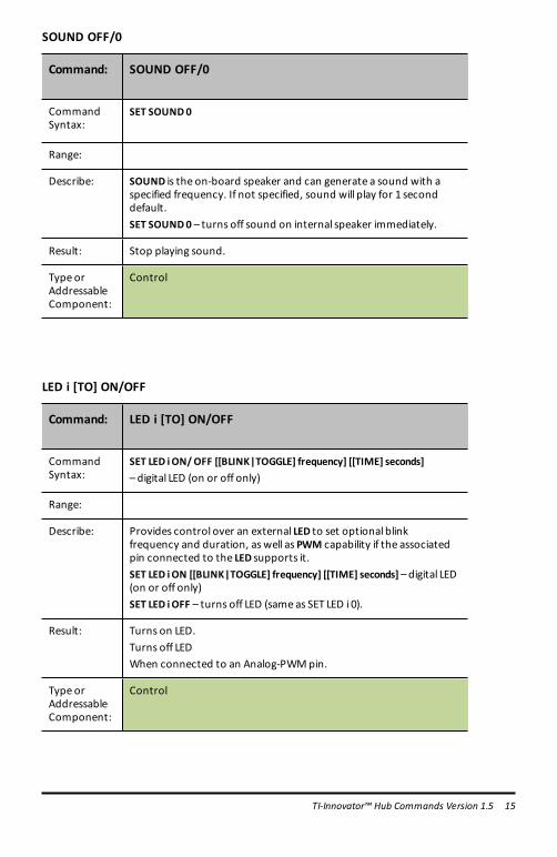
SOUND OFF/0
Command: SOUND OFF/0
CommandSyntax:
SET SOUND0
Range:
Describe: SOUND is the on-board speaker and can generate a sound with aspecified frequency. If not specified, sound will play for 1 seconddefault.SET SOUND0 – turns off sound on internal speaker immediately.
Result: Stop playing sound.
Type orAddressableComponent:
Control
LED i [TO] ON/OFF
Command: LED i [TO] ON/OFF
CommandSyntax:
SET LED iON/OFF [[BLINK|TOGGLE] frequency] [[TIME] seconds]– digital LED (on or off only)
Range:
Describe: Provides control over an external LED to set optional blinkfrequency and duration, as well as PWM capability if the associatedpin connected to the LED supports it.SET LED iON [[BLINK|TOGGLE] frequency] [[TIME] seconds] – digital LED(on or off only)SET LED iOFF – turns off LED (same as SET LED i 0).
Result: Turns on LED.Turns off LEDWhen connected to an Analog-PWMpin.
Type orAddressableComponent:
Control
TI-Innovator™ Hub Commands Version 1.5 15

16 TI-Innovator™ Hub Commands Version 1.5
LED i [TO] 0-255
Command: LED i [TO] 0-255
CommandSyntax:
SET LED i 0-255 [[BLINK|TOGGLE] frequency] [[TIME] seconds]– analog LED (pwm duty cycyle)
Range:
Describe: Provides control over an external LED to set optional blinkfrequency and duration, as well as PWM capability if the associatedpin connected to the LED supports it.SET LED i 0-255 [[BLINK|TOGGLE] frequency] [[TIME] seconds] – analogLED (pwm duty cycyle)
Result: When connected to an Analog-PWMpin.
Type orAddressableComponent:
Control
RGB i [TO] r g b [[BLINK|TOGGLE] frequency] [[TIME] seconds]
Command: RGB i [TO] r g b [[BLINK|TOGGLE] frequency] [[TIME]seconds]
CommandSyntax:
SET RGB i r g b [[BLINK|TOGGLE] frequency] [[TIME]seconds]
Range:
Describe: ExternalRGB LED controls, with sameoptions as available for the on-board COLOR object. Individual color components can beaddressed with the same index value i by name, RED i, GREEN i, BLUEi.
Result: Where r g b is r-value g-value b-value respectively, or operators fromON/OFF/STOP.
Type orAddressableComponent:
Control

COLOR.RED i [TO] ON/OFF/UP/DOWN/value [[BLINK|TOGGLE] frequency] [[TIME]seconds]
Command: COLOR.RED i [TO] ON/OFF/UP/DOWN/value[[BLINK|TOGGLE] frequency] [[TIME] seconds]
CommandSyntax:
SET COLOR.RED i [TO] ON/OFF/UP/DOWN/value [[BLINK|TOGGLE]frequency] [[TIME] seconds]
Range:
Describe: RED component of External RGB LED controls, with sameoptions asavailable for the on-board COLOR object. Individual colorcomponents can be addressed with the same index value i by name,RED i, GREEN i, BLUE i.
Result:
Type orAddressableComponent:
Control
COLOR.GREEN i [TO] ON/OFF/UP/DOWN/value [[BLINK|TOGGLE] frequency] [[TIME]seconds]
Command: COLOR.GREEN i [TO] ON/OFF/UP/DOWN/value[[BLINK|TOGGLE] frequency] [[TIME] seconds]
CommandSyntax:
SET COLOR.GREEN i [TO] ON/OFF/UP/DOWN/value [[BLINK|TOGGLE]frequency] [[TIME] seconds]
Range:
Describe: GREEN component of External RGB LED controls, with sameoptions as available for the on-board COLOR object. Individual colorcomponents can be addressed with the same index value i by name,RED i, GREEN i, BLUE i.
Result:
Type orAddressableComponent:
Control
TI-Innovator™ Hub Commands Version 1.5 17

18 TI-Innovator™ Hub Commands Version 1.5
COLOR.BLUE i [TO] ON/OFF/UP/DOWN/value [[BLINK|TOGGLE] frequency] [[TIME]seconds]
Command: COLOR.BLUE i [TO] ON/OFF/UP/DOWN/value[[BLINK|TOGGLE] frequency] [[TIME] seconds]
CommandSyntax:
SET COLOR.BLUE i [TO] ON/OFF/UP/DOWN/value [[BLINK|TOGGLE]frequency] [[TIME] seconds]
Range:
Describe: BLUE component of External RGB LED controls, with sameoptionsas available for the on-board COLOR object. Individual colorcomponents can be addressed with the same index value i by name,RED i, GREEN i, BLUE i.
Result:
Type orAddressableComponent:
Control
Note: For TI-RGB Array commands, please go to TI-RGB Array.
SPEAKER i [TO] frequency [[TIME] seconds]
Command: SPEAKER i [TO] frequency [[TIME] seconds]
CommandSyntax:
SET SPEAKER i [TO] frequency [[TIME] seconds]
Range:
Describe: Same as SOUND above, except sound is played on an externalspeaker attached to a digital output pin, available on any IN/OUTport, or the breadboard connector port.Note: On-board SOUND and external SPEAKER cannot be usedconcurrently.
Result: Play tonewith frequency given, optional duration in milliseconds,default = 1 second.
Type orAddressableComponent:
Control

TEMPO keyword for SOUND/SPEAKER
• Quick way to add repeated beeps• Equivalent to “blink” for SOUND• New optional keyword – TEMPO
SET SOUND 440 TEMPO 2 TIME 2
• 2 beeps per second for 2 seconds: total 4 beeps• The value for TEMPO can range from 0 to 10
CodeSample:
SET SOUND 440 TEMPO 2 TIME 5
SET SPEAKER 1 880 TEMPO 3 TIME 4
SET SOUND 400 TIME 5 TEMPO 0
is equivalent toSET SOUND 400 TIME 5
Both commandswill play the tone for 5 secondswithout any breaks.
POWER
Command: POWER i [TO] 0-100
CommandSyntax:
SET POWER 1 nwhere n is the intensity of the output from 0 - 100
SET POWER 1 50 – set the power to 50% of themaximum.
Range 0 – 100
Describe: POWER is used to control the output power and it typically usedwith aMOSFET and a battery source.It can be used to control the output to devices like amotor or apump.
Result: Controls the output intensity of the device connected through theMOSFET.
Type orAddressableComponent:
Control
TI-Innovator™ Hub Commands Version 1.5 19

20 TI-Innovator™ Hub Commands Version 1.5
SERVO i [TO] position
Command: SERVO i [TO] position
CommandSyntax:
SET SERVO i [TO] position.
CodeSample:
Range:
Describe: Servo motor control interface. Servos can be either continuous orsweep style servos.Position = value from -90 to 90, ranged to -90 to 90) - used withSWEEP SERVOS
Result: Sweep servos: position is a value from -90 to 90.Value 0 is same as specifying ZERO.
Type orAddressableComponent:
Control
SERVO i [TO] STOP
Command: SERVO i [TO] STOP
CommandSyntax:
SET SERVO i STOP
CodeSample:
Send("SET SERVO 1 STOP")
Range:
Describe: Servo motor control interface. Servos can be either continuous orsweep style servos.Note: Sweep style servoswill stop automatically at the end of thesweep.SET SERVO i STOP – stopsmotion on servo
Result: Halt any continuous servo operation in progress.Turn SERVO Off
Type or Control

Command: SERVO i [TO] STOP
AddressableComponent:
SERVO i [TO] ZERO
Command: SERVO i [TO] ZERO
CommandSyntax:
SET SERVO i ZERO/position
CodeSample:
Send("SET SERVO 1 ZERO")
Range:
Describe: Set servo to zero position on sweep servo, or no motion oncontinuous servo.
Result: Sweep servos: position is a value from -90 to 90.Value 0 is same as specifying ZERO.
Type orAddressableComponent:
Control
SERVO i [TO] [CW/CCW] speed [[TIME] seconds]
Command: SERVO i [TO] [CW/CCW] speed [[TIME] seconds]
CommandSyntax:
SET SERVO i CW/CCW speed [[TIME] seconds]
CodeSample:
Send("SET SERVO.CONTINUOUS 1 CW 100 TIME3")Wait 3
Range:
Describe: Speed from -100 to 100, CW/CCW optional, if speed <0, CCW, else CWunless CW/CCW keyword is specified,
TI-Innovator™ Hub Commands Version 1.5 21

22 TI-Innovator™ Hub Commands Version 1.5
Command: SERVO i [TO] [CW/CCW] speed [[TIME] seconds]
TIME optional, in seconds, default=1 second (for continuous servooperation)(CW/CCW required if TIME/seconds NOT specified.)
Result: Continuous servo where direction of rotation is specified, alongwith speed, from 0 (no motion) to 100 (fastest). Optional timeparameter used to specify how long the servo should rotate inseconds.
Type orAddressableComponent:
Control
ANALOG.OUT i [TO]
Command: ANALOG.OUT i [TO]
CommandSyntax:
SET ANALOG.OUT i 0-255 [[BLINK|TOGGLE] frequency] [[TIME] seconds]
Range:
Describe: Software (or hardware, if available) generated pulse-widthmodulation output at 490Hzwith the specified duty cycle between0 (off) and 255 (on). The PWMoutput can be toggled at a frequencyfrom 0.1 to 20.0Hz for a given duration. If no duration is given, thePWMcontinues until stopped or turned off.SET ANALOG.OUT i 0-255 [[BLINK|TOGGLE] frequency] [[TIME] seconds]
Result: Generate pwm value (hw or sw) on analog output object.
Type orAddressableComponent:
Control
ANALOG.OUT i OFF|STOP
Command: ANALOG.OUT i OFF|STOP
CommandSyntax:
SET ANALOG.OUT iOFFSET ANALOG.OUT i STOP
Range:

Command: ANALOG.OUT i OFF|STOP
Describe: Software (or hardware, if available) generated pulse-widthmodulation output at 490Hzwith the specified duty cycle between0 (off) and 255 (on). The PWMoutput can be toggled at a frequencyfrom 0.1 to 20.0Hz for a given duration. If no duration is given, thePWMcontinues until stopped or turned off.SET ANALOG.OUT iOFFSET ANALOG.OUT i STOP
Result: Turn off pwm on associated pin, including blinking, etc.
Type orAddressableComponent:
Control
VIB.MOTOR i [TO] PWM
Command: VIB.MOTOR i [TO] PWM
CommandSyntax:
SET VIB.MOTOR i [TO] PWM
Range: PWM from 0 (none) and 255 (full on)
Describe: Vibration motor control interface.
Result: Vibrations : intensity is a value from 0 to 255.
Type orAddressableComponent:
Control
VIB.MOTOR i [TO] OFF|STOP
Command: VIB.MOTOR i [TO] OFF|STOP
CommandSyntax:
SET VIB.MOTOR iOFF|STOP
Range:
Describe: Vibration motor control interface.SET VIB.MOTOR iOFF|STOP – stopsmotion on vibrations
TI-Innovator™ Hub Commands Version 1.5 23

24 TI-Innovator™ Hub Commands Version 1.5
Command: VIB.MOTOR i [TO] OFF|STOP
Result: Shut down vibration motor.
Type orAddressableComponent:
Control
VIB.MOTOR i [TO] 0-255/UP/DOWN/ON/OFF [[BLINK|TOGGLE] freq] [[TIME]seconds]
Command: VIB.MOTOR i [TO] 0-255/UP/DOWN/ON/OFF[[BLINK|TOGGLE] freq] [[TIME] seconds]
CommandSyntax:
SET VIB.MOTOR i 0-255/UP/DOWN/ON/OFF [[BLINK|TOGGLE] freq][[TIME] seconds]
Range: PWM from 0 (none) and 255 (full on)
Describe: Run vibration motor with numerous options
Result: Run vibration motor with numerous optionsOptional time parameter used to specify how long the vibrationshould rotate in seconds.
Type orAddressableComponent:
Control
COLOR.RED [TO] r [[BLINK|TOGGLE] frequency] [[TIME] seconds]
Command: COLOR.RED [TO] r [[BLINK|TOGGLE] frequency] [[TIME]seconds]
CommandSyntax:
Send("SET COLOR.RED...")ON/OFF/UP/DOWN/STOP/0-255 (red element)[BLINK frequency] (inHz)[TIME duration] (in secs)
Range:
Describe: RED component of On-board COLOR RGB LED. Can have a blinkfrequency, and blink time for entire item, or for each component

Command: COLOR.RED [TO] r [[BLINK|TOGGLE] frequency] [[TIME]seconds]
individually, as well as PWM levels given individually, or at one time.
Result: Where r is red level, or operators from ON/OFF/UP/DOWN/STOP.
Type orAddressableComponent:
Control
COLOR.GREEN [TO] g [[BLINK|TOGGLE] frequency] [[TIME] seconds]
Command: COLOR.GREEN [TO] g [[BLINK|TOGGLE] frequency] [[TIME]seconds]
CommandSyntax:
SET COLOR.GREEN [TO] g [[BLINK|TOGGLE] frequency] [[TIME] seconds]
Range:
Describe: GREEN component of On-board COLOR RGB LED. Can have a blinkfrequency, and blink time for entire item, or for each componentindividually, as well as PWM levels given individually, or at one time.
Result: Where g is green level, or operators from ON/OFF/UP/DOWN/STOP.
Type orAddressableComponent:
Control
COLOR.BLUE [TO] b [[BLINK|TOGGLE] frequency] [[TIME] seconds]
Command: COLOR.BLUE [TO] b [[BLINK|TOGGLE] frequency] [[TIME]seconds]
CommandSyntax:
SET COLOR.BLUE [TO] b [[BLINK|TOGGLE] frequency] [[TIME] seconds]
Range:
Describe: BLUE component of On-board COLOR RGB LED. Can have a blinkfrequency, and blink time for entire item, or for each componentindividually, as well as PWM levels given individually, or at one time.
TI-Innovator™ Hub Commands Version 1.5 25

26 TI-Innovator™ Hub Commands Version 1.5
Command: COLOR.BLUE [TO] b [[BLINK|TOGGLE] frequency] [[TIME]seconds]
Result: Where b is blue level, or operators from ON/OFF/UP/DOWN/STOP.
Type orAddressableComponent:
Control
BUZZER i [TO] ON [TIME seconds]
Command: BUZZER i [TO] ON [TIME seconds]
CommandSyntax:
SET BUZZER iON [[TIME] seconds]
Range:
Describe: Used to turn ON or OFF a tone on an active BUZZER for either 1second default, or given length of time.SET BUZZER iON [[TIME] seconds]
Result: Sound tone on ACTIVE buzzer for 1 second, or specified duration inseconds.
Type orAddressableComponent:
Control
BUZZER i [TO] OFF
Command: BUZZER i [TO] OFF
CommandSyntax:
SET BUZZER iOFF
Range:
Describe: Used to turn ON or OFF a tone on an active BUZZER for either 1second default, or given length of time.SET BUZZER iOFF
Result: Turn off tone on active buzzer.
Type orAddressableComponent:
Control

RELAY i [TO] ON/OFF
Command: RELAY i [TO] On/Off
CommandSyntax:
SET RELAY iON/OFF /0/1 [[TIME] seconds].
Range: Turns the specified RELAYON or OFF for the given specified TIME inseconds.
Describe: Control interface to an external RELAY control.SET RELAY iON/OFF/1/0 [[TIME] seconds]
Result: Turns RELAY on or off
Type orAddressableComponent:
ControlRELAY
SQUAREWAVE i [TO] frequency [duty [[TIME] seconds]]
Command: SQUAREWAVE i [TO] frequency [duty [[TIME] seconds]]
CommandSyntax:
SET SQUAREWAVE i frequency [duty]
Range:
Describe: SQUAREWAVE is used to generate a squarewave form with a defaultduty cycle of 50% with frequencies from 0.1Hz to 500Hz.frequencies slower than 0.1Hz are set to 0.1Hz. frequencies above500Hz are set to 500Hz. The optional duty cycle is a value from 1 to99.SET SQUAREWAVE i frequency [duty]
Result: Generate a digital squarewave from 1 to 500hz at 1-99duty cycle onup to 6pins (i=1-4) duty=50% default, seconds=1.0 default.
Type orAddressableComponent:
Control
TI-Innovator™ Hub Commands Version 1.5 27

28 TI-Innovator™ Hub Commands Version 1.5
SQUAREWAVE i OFF
Command: SQUAREWAVE i OFF
CommandSyntax:
SET SQUAREWAVE iOFFfrequency [duty]
Range:
Describe: SQUAREWAVE is used to generate a squarewave form with a defaultduty cycle of 50% with frequencies from 0.1Hz to 500Hz.frequencies slower than 0.1Hz are set to 0.1Hz. frequencies above500Hz are set to 500Hz. The optional duty cycle is a value from 1 to99.SET SQUAREWAVE iOFF – turn off squarewave generation
Result: Stop generating squarewave output.
Type orAddressableComponent:
Control
DIGITAL.OUT i [TO] ON/OFF/HIGH/LOW/[[BLINK|TOGGLE] frequency] [[TIME]seconds]
Command: DIGITAL.OUT i [TO] ON/OFF/HIGH/LOW/[[BLINK|TOGGLE]frequency] [[TIME] seconds]
CommandSyntax:
SET DIGITAL.OUT i [TO] ON/OFF/HIGH/LOW [[BLINK|TOGGLE]frequency] [[TIME] seconds]
Range:
Describe: Used to generate output digital signal(s).SET DIGITAL.OUT iON/OFF/HIGH/LOW [[BLINK|TOGGLE] frequency][[TIME] seconds]
Result: Digital.out operations.
Type orAddressableComponent:
Control

DIGITAL.OUT i [TO] OUTPUT/CLOCK
Command: DIGITAL.OUT i [TO] OUTPUT/CLOCK
CommandSyntax:
SET DIGITAL.OUT i [TO] OUTPUT/CLOCK
Range:
Describe: Output or drive a clock pulse - digital.out other operations.
Result: Output or drive a clock pulse - digital.out other operations.
Type orAddressableComponent:
Control
DIGITAL.IN i [TO] INPUT/PULLUP/PULLDOWN
Command: DIGITAL.IN i [TO] INPUT/PULLUP/PULLDOWN
CommandSyntax:
SET DIGITAL.IN i [TO] INPUT/PULLUP/PULLDOWN
Range:
Describe: Used for Pulldown and/or pullup control for digital.in operations.
Result: Pulldown and pullup control for digital.in operations.
Type orAddressableComponent:
Control
AVERAGING [TO] n
Command: AVERAGING [TO] n
Advanced user
CommandSyntax:
AVERAGING.[TO] n
Range:
Describe: Global setting for how many timeswe sample analog inputs when
TI-Innovator™ Hub Commands Version 1.5 29

30 TI-Innovator™ Hub Commands Version 1.5
Command: AVERAGING [TO] n
Advanced user
obtaining a reading from a sensor using analog inputn - (global default)
Result: Sample analog inputs 'n' times, averaging results (default is 3 unlesschanged; sets "global" averaging value.)
Type orAddressableComponent:
SettingDefault if not set with this command is 3
Note: Global averaging value can be individually overridden by sensor byusing theAVERAGE command on an item.This command sets the global averaging count to use only on newlyconnected objects. This does not affect already CONNECTedobjects.AVERAGE object (index) value sets/changes the averaging count touse on an already connected object.The globalAVERAGING value set by the SET AVERAGINGoperationwill not take effect on an object until is disconnected andreconnected. The global initial default is 3 samples per reading. Oncean object is connected, theAVERAGE command can be used tochange the value.

BBPORT
Command: SET BBPORT [TO] nn [MASK value]
CommandSyntax:
SET BBPORT TO 100SET BBPORT TO 0X80
Range
Describe: The SET operation on BBPORT is used to set the respective bits ofthe BB port to a 1or 0 value based on the value given, the optionalMASK (which is used to specify which pins are being used as digitaloutputs) and the internal connection mask specified in theCONNECT BBPORT operation.
Result:
Type orAddressableComponent:
Control
TI-Innovator™ Hub Commands Version 1.5 31

32 TI-Innovator™ Hub Commands Version 1.5
READThe READ command generates responses based on what is being requested.
Tells the Innovator to obtain data from the specified sensor, control, port, pin, or statusinformation including the setup of the hub, such as flow control, error settings, etc.Must be followed by a Get() operation to receive the requested data.
CE Calculators TI-Nspire™ CX
BRIGHTNESS
Command: BRIGHTNESS
CommandSyntax:
READBRIGHTNESS
Range:
Describe: Returns the current internal reading from the on-board ambientlight sensor.Note the optional keywords ofRANGE and AVERAGE can beappended to the command to return the current RANGE setting fortheBRIGHTNESS sensor if set or the current AVERAGE value appliedwhen reading the ADC to obtain the reading.READBRIGHTNESS
Result: Read on-board light sensor level.
Type or Control

Command: BRIGHTNESS
AddressableComponent:
BRIGHTNESS AVERAGE
Command: BRIGHTNESS AVERAGEAdvanced user
CommandSyntax:
READBRIGHTNESS.AVERAGE
Range:
Describe: Returns the current internal reading from the on-board ambientlight sensor.Note the optional keywords of RANGE and AVERAGE can beappended to the command to return the current RANGE setting fortheBRIGHTNESS sensor if set or the current AVERAGE value appliedwhen reading the ADC to obtain the reading.READBRIGHTNESS AVERAGE
Result: Read on-board light sensor level.
Type orAddressableComponent:
Control
BRIGHTNESS RANGE
Command: BRIGHTNESS RANGEAdvanced user
CommandSyntax:
READBRIGHTNESS.RANGE
Range:
Describe: Returns the current internal reading from the on-board ambientlight sensor.Note the optional keywords of RANGE and AVERAGE can be
TI-Innovator™ Hub Commands Version 1.5 33

34 TI-Innovator™ Hub Commands Version 1.5
Command: BRIGHTNESS RANGEAdvanced user
appended to the command to return the current RANGE setting fortheBRIGHTNESS sensor if set or the current AVERAGE value appliedwhen reading the ADC to obtain the reading.READBRIGHTNESS RANGE
Result: Read on-board light sensor level.
Type orAddressableComponent:
Control
DHT i
Command: DHT i
CommandSyntax:
READDHT i
Range: Temperature reading default is in CelsiusHumidity reading from 0 to 100%
Describe: Returns a list consisting of the current temperature, humidity, typeof sensor, and last cached read status. The temperature andhumidity can be obtained by themselves by appending theTEMPERATURE or HUMIDITY keywords to the end of the command.The type of sensor is indicated by a 1 for a DHT11, and a 2 for DHT22style sensors. The status values are: 1=OK, 2=Timeout,3=Checksum/bad reading.READDHT i– returns full cached information from last reading theDHT task obtained.READDHT i TEMPERATURE – returns latest temperature reading.READDHT iHUMIDITY – returns latest humidity reading.READDHT nTYPE - return the sensor type used (1=DHT11, 2=DHT22).READDHT n STATUS - return the current status of the sensorreadings provided. (1=OK, 2=Timeout, 3=Checksum error).
Result: Return list with current temperature in C, humidity in %, type(1=DHT11, 2=DHT22), and status (type/status only available in fulllist).Where the status = 1:OK, =2:Timeout, =3:Checksum.

Command: DHT i
Type orAddressableComponent:
Sensor
DHT i TEMPERATURE
Command: DHT i TEMPERATURE
CommandSyntax:
READDHT i TEMPERATURE
Range: Temperature reading default is in CelsiusHumidity reading from 0 to 100%
Describe: Returns a list consisting of the current temperature, humidity, typeof sensor, and last cached read status. The temperature andhumidity can be obtained by themselves by appending theTEMPERATURE or HUMIDITY keywords to the end of the command.The type of sensor is indicated by a 1 for a DHT11, and a 2 for DHT22style sensors. The status values are: 1=OK, 2=Timeout,3=Checksum/bad reading.READDHT i– returns full cached information from last reading theDHT task obtained.READDHT i TEMPERATURE – returns latest temperature reading.READDHT iHUMIDITY – returns latest humidity reading.READDHT nTYPE - return the sensor type used (1=DHT11, 2=DHT22).READDHT n STATUS - return the current status of the sensorreadings provided. (1=OK, 2=Timeout, 3=Checksum error).
Result: Returns temperature component.
Type orAddressableComponent:
Sensor
TI-Innovator™ Hub Commands Version 1.5 35

36 TI-Innovator™ Hub Commands Version 1.5
DHT i HUMIDITY
Command: DHT i HUMIDITY
CommandSyntax:
READDHT iHUMIDITY
Range: Temperature reading default is in CelsiusHumidity reading from 0 to 100%
Describe: Returns a list consisting of the current temperature, humidity, typeof sensor, and last cached read status. The temperature andhumidity can be obtained by themselves by appending theTEMPERATURE or HUMIDITY keywords to the end of the command.The type of sensor is indicated by a 1 for a DHT11, and a 2 for DHT22style sensors. The status values are: 1=OK, 2=Timeout,3=Checksum/bad reading.READDHT i– returns full cached information from last reading theDHT task obtained.READDHT i TEMPERATURE – returns latest temperature reading.READDHT iHUMIDITY – returns latest humidity reading.READDHT nTYPE - return the sensor type used (1=DHT11, 2=DHT22).READDHT n STATUS - return the current status of the sensorreadings provided. (1=OK, 2=Timeout, 3=Checksum error).
Result: Returns humidity component.
Type orAddressableComponent:
Sensor
RANGER i
Command: RANGER i
CommandSyntax:
READRANGER i
Range:
Describe: Return the current distancemeasurement from the specifiedultrasonic ranging device; distance in meters. If no measurement ismade due to the distance being too far; a value of 0will be returned.

Command: RANGER i
Valid measurements are in +meters.
Result: Read distance in meters from distance sensor.
Type orAddressableComponent:
Sensor
READ RANGER i TIME
Command: READ RANGER i TIME
CommandSyntax:
READRANGER i TIME
Range:
Describe: Additional functionality for RANGER - to return time of flight insteadof distance.The value is in seconds. And it is the round trip time for the signal.
Result: Retrieves the time-of-flight data readings for the specified RANGER.
Type orAddressableComponent:
Sensor
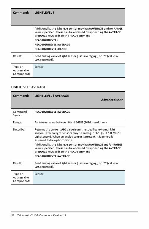
LIGHTLEVEL i
Command: LIGHTLEVEL i
CommandSyntax:
READ LIGHTLEVEL i
Range: An integer value between 0 and 16383 (14bit resolution)
Describe: Returns the current ADC value from the specified external lightsensor. External light sensorsmay be analog, or I2C (BH1750FVI I2CLight sensor). When an analog sensor is present, it is generallyassumed to be a photodiode.
TI-Innovator™ Hub Commands Version 1.5 37
38 TI-Innovator™ Hub Commands Version 1.5
Command: LIGHTLEVEL i
Additionally, the light level sensor may haveAVERAGE and/or RANGEvalues specified. These can be obtained by appending theAVERAGEor RANGE keywords to theREAD command.READ LIGHTLEVEL iREAD LIGHTLEVEL i AVERAGEREAD LIGHTLEVEL i RANGE
Result: Read analog value of light sensor (uses averaging), or I2C (value inLUX returned).
Type orAddressableComponent:
Sensor
LIGHTLEVEL i AVERAGE
Command: LIGHTLEVEL i AVERAGEAdvanced user
CommandSyntax:
READ LIGHTLEVEL i AVERAGE
Range: An integer value between 0 and 16383 (14bit resolution)
Describe: Returns the current ADC value from the specified external lightsensor. External light sensorsmay be analog, or I2C (BH1750FVI I2CLight sensor). When an analog sensor is present, it is generallyassumed to be a photodiode.Additionally, the light level sensor may haveAVERAGE and/or RANGEvalues specified. These can be obtained by appending theAVERAGEor RANGE keywords to theREAD command.READ LIGHTLEVEL i AVERAGE
Result: Read analog value of light sensor (uses averaging), or I2C (value inLUX returned).
Type orAddressableComponent:
Sensor

LIGHTLEVEL i RANGE
Command: LIGHTLEVEL i RANGEAdvanced user
CommandSyntax:
READ LIGHTLEVEL i RANGE
Range: An integer value between 0 and 16383 (14bit resolution)
Describe: Returns the current ADC value from the specified external lightsensor. External light sensorsmay be analog, or I2C (BH1750FVI I2CLight sensor). When an analog sensor is present, it is generallyassumed to be a photodiode.Additionally, the light level sensor may haveAVERAGE and/or RANGEvalues specified. These can be obtained by appending theAVERAGEor RANGE keywords to theREAD command.READ LIGHTLEVEL i RANGE
Result: Read analog value of light sensor (uses averaging), or I2C (value inLUX returned).
Type orAddressableComponent:
Sensor
TEMPERATURE i
Command: TEMPERATURE i
CommandSyntax:
READTEMPERATURE i
Range: Temperature reading default is in Celsius. The range depends on thespecific temperature sensor being used.Humidity reading from 0 to 100%
Describe: Returns the current temperature reading from the associatedtemperature sensor. The temperature is given, by default, in Celsius.READTEMPERATURE i
Result: Return current temperature reading in Celsius.
Type orAddressableComponent:
Sensor
TI-Innovator™ Hub Commands Version 1.5 39

40 TI-Innovator™ Hub Commands Version 1.5
TEMPERATURE i AVERAGE
Command: TEMPERATURE i AVERAGEAdvanced user
CommandSyntax:
READTEMPERATURE i AVERAGE
Range: Temperature reading default is in Celsius. The range depends on thespecific temperature sensor being used.Humidity reading from 0 to 100%
Describe: Returns the current temperature reading from the associatedtemperature sensor. The temperature is given, by default, in Celsius.READTEMPERATURE i AVERAGE
Result: Return current temperature reading in Celsius.
Type orAddressableComponent:
Sensor
TEMPERATURE i CALIBRATION
Command: TEMPERATURE i CALIBRATION
Advanced user
CommandSyntax:
READTEMPERATURE i CALIBRATION
Range: Temperature reading default is in Celsius. The range depends on thespecific temperature sensor being used.Humidity reading from 0 to 100%
Describe: Returns the current temperature reading from the associatedtemperature sensor. The temperature is given, by default, in Celsius.
Result: Returns list with current {c1,c2,c3,r} values used for connectedanalog temperature sensor.
Type orAddressableComponent:
Sensor

MOISTURE i
Command: MOISTURE i
CommandSyntax:
READMOISTURE i
Range: An integer value between 0 and 16383 (14bit resolution)
Describe: Return the current analog level reported by themoisture sensorspecified. Supports theAVERAGE and RANGE options.READMOISTURE iREADMOISTURE i AVERAGEREADMOISTURE i RANGE
Result: Read analog value ofmoisture sensor (uses averaging).
Type orAddressableComponent:
Sensor
MOISTURE i AVERAGE
Command: MOISTURE i AVERAGEAdvanced user
CommandSyntax:
READMOISTURE i AVERAGE
Range:
Describe: Return the current analog level reported by themoisture sensorspecified. Supports theAVERAGE and RANGE options.READMOISTURE i AVERAGE
Result: Read analog value ofmoisture sensor (uses averaging).
Type orAddressableComponent:
Sensor
TI-Innovator™ Hub Commands Version 1.5 41

42 TI-Innovator™ Hub Commands Version 1.5
MOISTURE i RANGE
Command: MOISTURE i RANGE
CommandSyntax:
READMOISTURE i RANGE
Range:
Describe: Return the current analog level reported by themoisture sensorspecified. Supports theAVERAGE and RANGE options.READMOISTURE i RANGE
Result: Read analog value ofmoisture sensor (uses averaging).
Type orAddressableComponent:
Sensor
MAGNETIC
Command: MAGNETIC i
CommandSyntax:
READMAGNETIC i
Range 0or 10 – no magnetic field is detected1 –magnetic field is detected
Describe: TheMAGNETIC sensor is used to detect the presence of amagneticfield. It uses theHall effect. It is also known as a Hall effect sensor.
Result:
Type orAddressableComponent:
Sensor

VERNIER
Command: READ VERNIER i
CommandSyntax:
READVERNIER 1
Range Depends on the specific Vernier analog sensor connected to the TI-SensorLink
Describe: Reads the value from the sensor specified in the command.
Result:
Type orAddressableComponent:
Sensor
ANALOG.IN i
Command: ANALOG.IN i
CommandSyntax:
READ.ANALOG.IN i
Range:
Describe: Generic analog input sensor.READANALOG.IN i–will return the ADC reading on the analog inputassociated with the object.
Result: Reads generic ANALOG.IN input object
Type orAddressableComponent:
Sensor
ANALOG.IN i AVERAGE
Command: ANALOG.IN i AVERAGEAdvanced user
CommandSyntax:
READ.ANALOG.IN i AVERAGE
Range:
TI-Innovator™ Hub Commands Version 1.5 43

44 TI-Innovator™ Hub Commands Version 1.5
Command: ANALOG.IN i AVERAGEAdvanced user
Describe: READANALOG IN iAVERAGE – gets the current averaging value forthe object.
Result: Reads generic ANALOG.IN input object
Type orAddressableComponent:
Sensor
ANALOG.IN i RANGE
Command: ANALOG.IN i RANGEAdvanced user
CommandSyntax:
READ.ANALOG.IN i RANGE
Range:
Describe: READANALOG IN i RANGE – returns the upper and lower rangevalues associated with the object if specified, or error otherwise
Result: Reads generic ANALOG.IN input object
Type orAddressableComponent:
Sensor
ANALOG.OUT i
Command: ANALOG.OUT i
CommandSyntax:
READANALOG.OUT i
Range:
Describe: Returns current PWMduty cycle if the output is on, or 0 if not on.
Result: Reads current PWMduty cycle on pin, 0 if none.
Type orAddressableComponent:
Control

DIGITAL.IN i
Command: DIGITAL.IN i
CommandSyntax:
READDIGITAL.IN i
Range:
Describe: Returns the current state of the digital pin connected to theDIGITALobject, or the cached state of the digital output value lastSET to the object.
Result: Return 0 (low), 1 (high).
Type orAddressableComponent:
Control/Sensor
SWITCH i
Command: SWITCH i
CommandSyntax:
READSWITCH i
Range:
Describe: Returns the current state of the associated switch. If the switch isconnected, a value of 1 is returned. Not connected returns a valueof 0. If the switch was connected since the last reading, but is nolonger connected, a value of 2 is returned.READSWITCH i
Result: Returns state of switch (same status as BUTTON object, 0=notpressed, 1=pressed, 2=was pressed).
Type orAddressableComponent:
Sensor
TI-Innovator™ Hub Commands Version 1.5 45

46 TI-Innovator™ Hub Commands Version 1.5
BUTTON i
Command: BUTTON i
CommandSyntax:
READBUTTON i
Range:
Describe: Reads the current cached state of the button.A return value of 0 = not pressed, 1 = currently pressed, 2 =waspressedand released since the last reading.READBUTTON i
Result: Read state of button/switch n - 0=not pressed, 1=pressed, 2=waspressed.
Type orAddressableComponent:
Sensor
MOTION i
Command: MOTION i
CommandSyntax:
READMOTION i
Range:
Describe: Return the current PIR Motion sensor information. PIR Motionsensors are digital in nature, so are treated similar to a button in thatthe value returned indicatesmotion presence or not.0=no motion detected.1=motion detected.2=motion was detected.
Result: Read state of PIR Motion detector - 0=no motion, 1=motion,2=motion was detected but none now.
Type orAddressableComponent:
Sensor
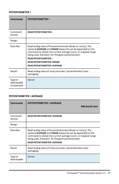
POTENTIOMETER i
Command: POTENTIOMETER i
CommandSyntax:
READPOTENTIOMETER i
Range:
Describe: Read analog value of the potentiometer (linear or rotary). TheoptionalAVERAGE and RANGE keywords can be appended to thecommand to obtain the current average count, or mapped rangebeing used, if present, for the given potentiometer.READPOTENTIOMETER iREADPOTENTIOMETER i RANGEREADPOTENTIOMETER i AVERAGE
Result: Read analog value of rotary encoder / potentiometer (usesaveraging).
Type orAddressableComponent:
Sensor
POTENTIOMETER i AVERAGE
Command: POTENTIOMETER i AVERAGEAdvanced user
CommandSyntax:
READPOTENTIOMETER i AVERAGE
Range:
Describe: Read analog value of the potentiometer (linear or rotary). TheoptionalAVERAGE and RANGE keywords can be appended to thecommand to obtain the current average count, or mapped rangebeing used, if present, for the given potentiometer.READPOTENTIOMETER i AVERAGE
Result: Read analog value of rotary encoder / potentiometer (usesaveraging).
Type orAddressable
Sensor
TI-Innovator™ Hub Commands Version 1.5 47

48 TI-Innovator™ Hub Commands Version 1.5
Command: POTENTIOMETER i AVERAGEAdvanced user
Component:
POTENTIOMETER i RANGE
Command: POTENTIOMETER i RANGEAdvanced user
CommandSyntax:
READPOTENTIOMETER i RANGE
Range:
Describe: Read analog value of the potentiometer (linear or rotary). TheoptionalAVERAGE and RANGE keywords can be appended to thecommand to obtain the current average count, or mapped rangebeing used, if present, for the given potentiometer.READPOTENTIOMETER i RANGE
Result: Read analog value of rotary encoder / potentiometer (usesaveraging).
Type orAddressableComponent:
Sensor
THERMISTOR i
Command: THERMISTOR i
CommandSyntax:
READTHERMISTOR i
Range:
Describe: Returns the current temperature reading from the associatedthermistor sensor. Temperature is returned in Celsius.
Result: Return current thermistor temperature in Celsius.

Command: THERMISTOR i
Type orAddressableComponent:
Sensor
THERMISTOR i AVERAGE
Command: THERMISTOR i AVERAGEAdvanced user
CommandSyntax:
READTHERMISTOR iAVERAGE
Range:
Describe: Returns the current temperature reading from the associatedthermistor sensor. Temperature is returned in Celsius.
Result: Return current thermistor temperature in Celsius.
Type orAddressableComponent:
Sensor
THERMISTOR i CALIBRATION
Command: THERMISTOR i CALIBRATION
Advanced user
CommandSyntax:
READTHERMISTOR i CALIBRATION
Range:
Describe: Returns the current temperature reading from the associatedthermistor sensor. Temperature is returned in Celsius.
Result: Returns list with current {c1,c2,c3,r} values used for connectedthermistor.
Type or Sensor
TI-Innovator™ Hub Commands Version 1.5 49

50 TI-Innovator™ Hub Commands Version 1.5
Command: THERMISTOR i CALIBRATION
Advanced user
AddressableComponent:
AVERAGING
Command: AVERAGING
Advanced user
CommandSyntax:
READAVERAGING
Range:
Describe: Returns the current global setting for the analog averaging defaultvalue.
Result: Return current oversampling/averaging count for sampling analoginputs (this is theGLOBALdefault value currently in use).
Type orAddressableComponent:
Setting
LOUDNESS i
Command: LOUDNESS i
CommandSyntax:
READ LOUDNESS i
Range:
Describe: Return the current analog level reported by the sound loudnesslevel sensor specified. Supports theAVERAGE and RANGE options.READ LOUDNESS iREAD LOUDNESS i AVERAGE

Command: LOUDNESS i
READ LOUDNESS i RANGE
Result: Return level of sound detected by sound sensor.
Type orAddressableComponent:
Sensor
LOUDNESS i AVERAGE
Command: LOUDNESS iAdvanced user
CommandSyntax:
READ LOUDNESS i AVERAGE
Range:
Describe: Return the current analog level reported by the sound loudnesslevel sensor specified. Supports theAVERAGE and RANGE options.READ LOUDNESS i AVERAGE
Result: Return level of sound detected by sound sensor.
Type orAddressableComponent:
Sensor
LOUDNESS i RANGE
Command: LOUDNESS i RANGEAdvanced user
CommandSyntax:
READ LOUDNESS i.RANGE
Range:
Describe: Return the current analog level reported by the sound loudnesslevel sensor specified. Supports theAVERAGE and RANGE options.READ LOUDNESS i
TI-Innovator™ Hub Commands Version 1.5 51

52 TI-Innovator™ Hub Commands Version 1.5
Command: LOUDNESS i RANGEAdvanced user
READ LOUDNESS i AVERAGEREAD LOUDNESS i RANGE
Result: Return level of sound detected by sound sensor.
Type orAddressableComponent:
Sensor

BBPORT
Command: READ BBPORT
CommandSyntax:
READBBPORT [MASK value]Get B
Range
Describe: Reads the connected pins of theBBPORT object as inputs, switchingpins from output state to input state. The default connection masklimits the pins that are used in this operation, as does the optionalMASK value provided.
Result:
Type orAddressableComponent:
Sensor
TI-Innovator™ Hub Commands Version 1.5 53

54 TI-Innovator™ Hub Commands Version 1.5
TIMER
Command: TIMER
CommandSyntax:
READTIMER
CodeSample:
While getkey() <> "esc"Send "READ BRIGHTNESS"Get bSend "READ TIMER"Get tDisp "Brightness: ", b, "Timer: ", tWait 1EndWhile
Range
Describe: This is a built-in sensor. There is no need for CONNECT orDISCONNECT.The Timer is set to 0 at power up. It will increasemonotonically.
Result:
Type orAddressableComponent:
Sensor

SettingsSettings menu contains operations to set the state of digital and analog pin operationssuch as the LED in the TI-Innovator™ Hub or a connected servo motor movement tostates such as ON, OFF, CW (clockwise), and CCW (counterclockwise).
– 1: ON– 2: OFF– 3: TO– 4: TIME– 5: BLINK– 6: TEMPERATURE– 7: HUMIDITY– 8: CW– 9: CCW– 0: NAMED– A: PULLDOWN– B: INPUT– C: PH– D: FORCE10– E: FORCE50– F: PRESSURE– G: PRESSURE2
CE Calculators TI-Nspire™ CX
WaitWait suspends execution of a program for a given time. Maximum time is 100 seconds.During the wait time, the busy indicator is on in the top-right corner of the screen.
Wait may be used in TI-Innovator™ Hub programs to allow time for sensor or controlcommunications prior to the program executing the next command line.
CE Calculators TI-Nspire™ CX
TI-Innovator™ Hub Commands Version 1.5 55

56 TI-Innovator™ Hub Commands Version 1.5
Wait
Command: Wait
CommandSyntax:
Wait timeInSecondsSuspends execution for a period of timeInSeconds seconds.
Range 0 through 100
Describe: Waitmay be used in TI-Innovator™ Hub programs to allow time forsensor or control communications prior to the program executingthe next command line.Wait is particularly useful in a program that needs a brief delay toallow requested data to become available.The argument timeInSecondsmust be an expression that simplifiesto a decimal value in the range 0 through 100. The commandrounds this value up to the nearest 0.1 seconds.Note: You can use theWait command within a user-definedprogram but not within a function.
Result: Wait suspends execution of a program for a given time. Maximumtime is 100 seconds. During thewait time, the busy indicator is on inthe top-right corner of the screen.
Type orAddressableComponent:
Not Applicable
Get(Get( Retrieves a value from a connected TI-Innovator™ Hub and stores the data to avariable on the receiving CE calculator.
CE Calculators
Get( command definition is specific to the TI-8x calculator and the cable connection viaDBus or USB. The CE calculator is USB connectivity only and here, Get( is designed forcommunication with the TI-Innovator™ Hub.
TI-Nspire™ CX
CE Calculators TI-Nspire™ CX

Get(
Command: Get(
CommandSyntax:
CE Calculators:Get(variable)
TI-Nspire™ CX platform:Get [promptString,] var[, statusVar]Get [promptString,] func(arg1, ...argn) [, statusVar]
Range
Describe:
Result: Programming command: Retrieves a value from a connected TI-Innovator™ Hub and assigns the value to variable var.The valuemust be requested:• In advance, through a Send "READ ..." command.— or—• By embedding a "READ ..." request as the optional
promptString argument. This method lets you use asingle command to request the value and retrieve it. (TI-Nspire™ CX platform only).
Implicit simplification takes place. For example, a received string of"123" is interpreted as a numeric value.
The information below applies only on the TI-Nspire CX platform:To preserve the string, useGetStr instead ofGet.If you include the optional argument statusVar, it is assigned a valuebased on the success of the operation. A value of zero means thatno data was received.In the second syntax, the func() argument allows a program tostore the received string as a function definition. This syntaxoperates as if the program executed the command:
Define func(arg1, ...argn) = received string
TI-Innovator™ Hub Commands Version 1.5 57

58 TI-Innovator™ Hub Commands Version 1.5
Command: Get(
The program can then use the defined function func().Note: You can use theGet command within a user-defined programbut not within a function.
Type orAddressableComponent:
All input devices.
eval(The software evaluates expression Expr and replaces the eval() statement with theresult as a character string.
The argument Expr must simplify to a real number.
CE Calculators TI-Nspire™ CX
eval(
Command: eval(
CommandSyntax:
eval(Expr)⇒string
Range
Describe: The software evaluates expression Expr and replaces the eval()statement with the result as a character string.The argument Exprmust simplify to a real number.
CE Calculators: eval() can be used as a standalone command outsidea TI-Innovator™ Hub command.TI-Nspire™ CX platform: eval() is valid only in the TI-Innovator™ HubCommand argument of programming commandsGet, GetStr, andSend.

Command: eval(
Result: CE Calculators: For debugging purposes, using the command lineDisp Ans immediately after a command line using Send( displays thecomplete string being sent.TI-Nspire™ CX platform: Although eval() does not display its result,you can view the resulting Hub command string after executing thecommand by inspecting any of the following special variables.iostr.SendAnsiostr.GetAnsiostr.GetStrAns
Type orAddressableComponent:
Not Applicable
TI-Innovator™ Hub Commands Version 1.5 59

60 TI-Innovator™ Hub Commands Version 1.5
CONNECT-OutputCONNECT associates a given control or sensor with a pin or port on the TI-Innovator. Ifthe specified control or sensor is currently in use, an error will be generated. If the pinor port specified in the CONNECT command is currently in use, an error will begenerated.
The CONNECT command does not generate an active response, but a variety of errorsmay occur during a connection attempt, such as pin-in-use, unsupported, invalidoptions, bad options, etc.
CONNECT 'something i' [TO] IN1/IN2/IN3/OUT1/OUT2/OUT3/BB1
Command: CONNECT
CommandSyntax:
CONNECT
Range:
Describe: Associates a sensor or controlwith a given port or pin(s). Places therespective pin(s) in use
Result:
Type orAddressableComponent:
CE Calculators TI-Nspire™ CX
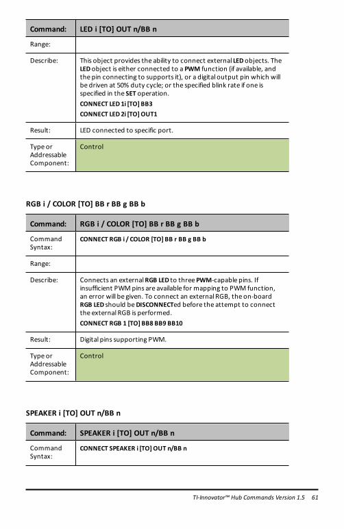
LED i [TO] OUT n/BB n
Command: LED i [TO] OUT n/BB n
CommandSyntax:
CONNECT LED i [TO] OUT n/BB n
Command: LED i [TO] OUT n/BB n
Range:
Describe: This object provides the ability to connect external LEDobjects. TheLEDobject is either connected to a PWM function (if available, andthe pin connecting to supports it), or a digital output pin which willbe driven at 50% duty cycle; or the specified blink rate if one isspecified in the SET operation.CONNECT LED 1i [TO] BB3CONNECT LED 2i [TO] OUT1
Result: LED connected to specific port.
Type orAddressableComponent:
Control
RGB i / COLOR [TO] BB r BB g BB b
Command: RGB i / COLOR [TO] BB r BB g BB b
CommandSyntax:
CONNECT RGB i / COLOR [TO] BB r BB g BB b
Range:
Describe: Connects an externalRGB LED to three PWM-capable pins. Ifinsufficient PWMpins are available for mapping to PWM function,an error will be given. To connect an external RGB, the on-boardRGB LED should beDISCONNECTed before the attempt to connectthe external RGB is performed.CONNECT RGB 1 [TO] BB8 BB9 BB10
Result: Digital pins supporting PWM.
Type orAddressableComponent:
Control
SPEAKER i [TO] OUT n/BB n
Command: SPEAKER i [TO] OUT n/BB n
CommandSyntax:
CONNECT SPEAKER i [TO] OUT n/BB n
TI-Innovator™ Hub Commands Version 1.5 61

62 TI-Innovator™ Hub Commands Version 1.5
Command: SPEAKER i [TO] OUT n/BB n
Range:
Describe: Connect an external speaker for sound generation. Requires adigital output pin.CONNECT SPEAKER 1 [TO] OUT 1CONNECT SPEAKER i [TO] BB 3
Result: Connect a speaker to a digital output port or pin.
Type orAddressableComponent:
Control
POWER
Command: CONNECT POWER n [TO] OUT1/OUT2/OUT3
CommandSyntax:
CONNECT POWER n [TO] OUT1/OUT2/OUT3
Range
Describe: Connects a POWER object to the specified analog output port.Default PWM value is zero.
Result: The named POWER device can be used in the program after aCONNECT command.
Type orAddressableComponent:
Control
SERVO.CONTINUOUS i [TO] BB 6
Command: SERVO.CONTINUOUS i [TO] BB 6
CommandSyntax:
CONNECT SERVO.CONTINUOUS i [TO] BB 6
CodeSample:
Range:

Command: SERVO.CONTINUOUS i [TO] BB 6
Describe: Used to connect either a normal sweep servo motor, or acontinuous servo motor. External power must be provided beforeattempting to connect the servo.CONNECT SERVO.CONTINUOUS i [TO] BB 6
Result: Servo motor with -90 to 90degreemovement.
Type orAddressableComponent:
Control
ANALOG.OUT i [TO] OUT i/BB i
Command: ANALOG.OUT i [TO] OUT n/BB n
CommandSyntax:
CONNECT ANALOG.OUT i [TO] OUT n/BB n
Range:
Describe: Connect a generic “analog”output control to a pin/port thatsupports analog input. ANALOG.OUT shares number spacewithDCMOTOR and SQUAREWAVE objects.CONNECT ANALOG.OUT i [TO] OUT 1CONNECT ANALOG.OUT i [TO] BB 4CONNECT ANALOG.OUT i [TO] BB 1
Result: Connect analog output to pin. If pin supports hardware pulsewithmodulation (PWM), the object uses.If the pin does not support hardware-generated PWM, the sketchwill generate PWM in software at 490Hzwith the duty cycle specficbetween 0 (none) and 255 (full on).
Type orAddressableComponent:
Control
VIB.MOTOR
Command: VIB.MOTOR i [TO] PWM
CommandSyntax:
SET VIB.MOTOR i [TO] PWM
TI-Innovator™ Hub Commands Version 1.5 63

64 TI-Innovator™ Hub Commands Version 1.5
Command: VIB.MOTOR i [TO] PWM
Range: PWM from 0 (none) and 255 (full on)
Describe: Vibration motor control interface.
Result: Vibrations : intensity is a value from 0 to 255.
Type orAddressableComponent:
Control
BUZZER i [TO] OUT n/BB n
Command: BUZZER i [TO] OUT n/BB n
CommandSyntax:
CONNECT BUZZER i [TO] OUT n/BB n
Range:
Describe: Connect an external active buzzer to an output digital pin. Activebuzzers play a tonewhen their signal is set high/on, and stop thetonewhen the signal is dropped to ground. For piezo or passivebuzzers, use the SPEAKER object type to allow generation ofmultiple tones.CONNECT BUZZER i [TO] OUT1
Result: ACTIVE buzzers connect to a digital pin.
Type orAddressableComponent:
Control
RELAY i [TO] OUT n/BB n
Command: RELAY i [TO] OUT n/BB n
CommandSyntax:
CONNECT RELAY i [TO] OUT n/BB n
Range:
Describe: With external power required, connect a relay module to a givencontrol signal pin. Since the control is digital, as long as externalpower is present, any pin may be used.

Command: RELAY i [TO] OUT n/BB n
CONNECT RELAY 1 [TO] BB 3CONNECT RELAY 1 [TO] OUT 2
Result: Relays.
Type orAddressableComponent:
Control
SERVO i [TO] OUT 3
Command: SERVO i [TO] OUT 3
CommandSyntax:
CONNECT SERVO i [TO] OUT 3
CodeSample:
Range:
Describe: Used to connect either a normal sweep servo motor, or acontinuous servo motor. External power must be provided beforeattempting to connect the servo.Note: Servo motors should only be connected to OUT 3.CONNECT SERVO 1 [TO] OUT 3
Result: Servo motor is connected to port.
Type orAddressableComponent:
Control
SQUAREWAVE i [TO] OUT n/BB n
Command: SQUAREWAVE i [TO] OUT n/BB n
CommandSyntax:
CONNECT SQUAREWAVE i [TO] OUT n/BB n
Range:
Describe: Connect a software generated digitalwaveform generator object.
TI-Innovator™ Hub Commands Version 1.5 65

66 TI-Innovator™ Hub Commands Version 1.5
Command: SQUAREWAVE i [TO] OUT n/BB n
These objects share the number-spacewith theDCMOTOR andANALOG.OUT output objects. The associated pin is configured as adigital output signal.CONNECT SQUAREWAVE n [TO] BB 2
Result: Digital output squarewave from 1 to 500hz.
Type orAddressableComponent:
Control
DIGITAL.OUT i [TO] OUT n/BB n [[AS] OUTPUT]
Command: DIGITAL.OUT i [TO] OUT n/BB n [[AS] OUTPUT]
CommandSyntax:
CONNECT DIGITAL.OUT i [TO] OUT n/BB n
Range:
Describe: Connects a generic digital object to a specified pin or port. Theconnected pin is configured either as a digital output signal, defaultLOW, or a digital input signal, default INPUTwith no pullup orpulldown enabled.The index number can refer to either an input or output. The indexis shared by both items since aDIGITAL signal can be either an inputor output.CONNECT DIGITAL.OUT 1 [TO] OUT n/BB n
Result: Connect pin to digital object default output state, default OUTPUT,low.
Type orAddressableComponent:
Control/Sensor

BBPORT
Command: CONNECT BBPORT
CommandSyntax:
CONNECT BBPORT [MASK value]
Range
Describe: When the optionalMASK is not specified, this command connectsall 10 BB pins to theBBPORT object as digital I/O pins.The optionalMASK parameter may be used to selectively connectspecific pins. Themask valuemay be specified in decimal, binary, orhexadecimal format. For example, 1023or 0X3FF selects all 10 pinsand is the default internalmask value used by theBBPORT object if aMASK is not specified.
Another example: If only pins BB1 and BB2are going to be used, amask value of 3 or 0x03will select on the two pins.
Result: If notMASK is specified, the program can read/write to all pins ofBBPORT.If aMASK is specified, the program can write to the specified pins.
Type orAddressableComponent:
Sensor
DCMOTOR i [TO] OUT n/BB n
Command: DCMOTOR i [TO] OUT n/BB n
CommandSyntax:
CONNECT DCMOTOR i [TO] OUT n/BB n
Range:
Describe: Connect an externalDCMotor object. This object requires thepresence of power on the external power connector to allowoperation. These objects share the number-spacewith theSQUAREWAVE output objects and ANALOG.OUT objects. Theassociated pin is configured as a digital output signal.CONNECT DCMOTOR i [TO] OUT1
Result: Connect DCMOTOR to a digital output pin.
Type orAddressableComponent:
Control
TI-Innovator™ Hub Commands Version 1.5 67

68 TI-Innovator™ Hub Commands Version 1.5
LIGHT
Command: LIGHT
CommandSyntax:
CONNECT LIGHT
Range:
Describe: This command is not needed for typical use since the on-boardLIGHT (i.e. RED LED) is automatically connected.Re-connect a previously disconnected on-board RED LED. TheLIGHT is always connected when the system is reset, or powered-on, or the BEGIN command is used to restore system state. No pinnumber is required.CONNECT LIGHT
Result: Connects on-board digital LED (red) to known fixed pin. Digital only.
Type orAddressableComponent:
Control
COLOR
Command: COLOR
CommandSyntax:
CONNECT COLOR
Range:
Describe: This command is not needed for typical use since the on-boardCOLOR LED is automatically connected.(Re-)connect the internalRGB LED. No pins are required for thiscommand to operate as the internal pins are known. This sensor isautomatically connected when the TI-Innovator is initially powered,and when theBEGIN command is used. When disconnected, twoPWM signals are freed for external use by other pins.CONNECT COLOR
Result: Connects on-board RGB LED to fixed pins on board. Uses 3PWMs.
Type orAddressableComponent:
Control

SOUND
Command: SOUND
CommandSyntax:
CONNECT SOUND
Range:
Describe: This command is not needed for typical use since the on-boardobject SOUND is automatically connected.Re-connect the on-board speaker for sound generation. No pinneeded as it uses known, fixed pin for signal.CONNECT SOUND
Result: Connects on-board speaker to fixed output digital pin.
Type orAddressableComponent:
Control
TI-Innovator™ Hub Commands Version 1.5 69

70 TI-Innovator™ Hub Commands Version 1.5
CONNECT-InputCONNECT associates a given control or sensor with a pin or port on the TI-Innovator. Ifthe specified control or sensor is currently in use, an error will be generated. If the pinor port specified in the CONNECT command is currently in use, an error will begenerated.
The CONNECT command does not generate an active response, but a variety of errorsmay occur during a connection attempt, such as pin-in-use, unsupported, invalidoptions, bad options, etc.
CONNECT 'something i' [TO] IN1/IN2/IN3/OUT1/OUT2/OUT3/BB1
Command: CONNECT
CommandSyntax:
CONNECT
Range:
Describe: Associates a sensor or controlwith a given port or pin(s). Places therespective pin(s) in use
Result:
Type orAddressableComponent:
CE Calculators TI-Nspire™ CX
DHT i [TO] IN n
Command: DHT i [TO] IN n
CommandSyntax:
CONNECT DHT i [TO] IN n

Command: DHT i [TO] IN n
Range: Temperature reading default is in CelsiusHumidity reading from 0 to 100%
Describe: TheDHT digital temperature humidity sensor can be connected viathis object. TheDHT can be either aDHT11 or DHT22 and is identifiedautomatically when connected to the system via a digital signal line.CONNECT DHT i [TO] IN1
Result: Digital humidity/temperature sensors (DHT11/DHT22, type is auto-detected).
Type orAddressableComponent:
Sensor
RANGER i [TO] IN n
Command: RANGER i [TO] IN n
CommandSyntax:
CONNECT RANGER i [TO] IN n
Range:
Describe: Connect an external ultrasonic distance rangingmodule to an inputport. CONNECT RANGER 1i [TO] IN 1
Result: Ultrasonic ranging sensors with either individual trigger/echo pins,or samepin used for trigger/echo.
Type orAddressableComponent:
Sensor
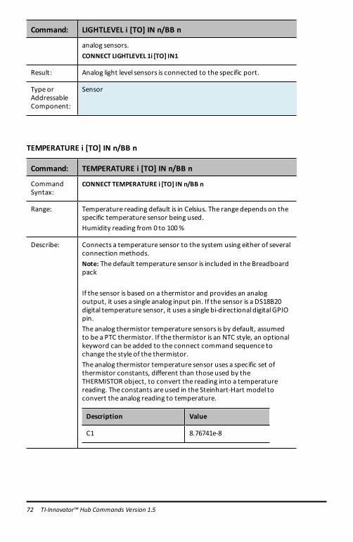
LIGHTLEVEL i [TO] IN n/BB n
Command: LIGHTLEVEL i [TO] IN n/BB n
CommandSyntax:
CONNECT LIGHTLEVEL i [TO] IN n/BB n
Range: An integer value between 0 and 16383 (14bit resolution)
Describe: Connects an external light sensor. External light sensors can be
TI-Innovator™ Hub Commands Version 1.5 71
72 TI-Innovator™ Hub Commands Version 1.5
Command: LIGHTLEVEL i [TO] IN n/BB n
analog sensors.CONNECT LIGHTLEVEL 1i [TO] IN1
Result: Analog light level sensors is connected to the specific port.
Type orAddressableComponent:
Sensor
TEMPERATURE i [TO] IN n/BB n
Command: TEMPERATURE i [TO] IN n/BB n
CommandSyntax:
CONNECT TEMPERATURE i [TO] IN n/BB n
Range: Temperature reading default is in Celsius. The range depends on thespecific temperature sensor being used.Humidity reading from 0 to 100%
Describe: Connects a temperature sensor to the system using either of severalconnection methods.Note: The default temperature sensor is included in the Breadboardpack
If the sensor is based on a thermistor and provides an analogoutput, it uses a single analog input pin. If the sensor is a DS18B20digital temperature sensor, it uses a single bi-directional digital GPIOpin.The analog thermistor temperature sensors is by default, assumedto be a PTC thermistor. If the thermistor is an NTC style, an optionalkeyword can be added to the connect command sequence tochange the style of the thermistor.The analog thermistor temperature sensor uses a specific set ofthermistor constants, different than those used by theTHERMISTOR object, to convert the reading into a temperaturereading. The constants are used in the Steinhart-Hart model toconvert the analog reading to temperature.
Description Value
C1 8.76741e-8

Command: TEMPERATURE i [TO] IN n/BB n
Description Value
C2 2.34125e-4
C3 1.129148e-3
R1– reference resistance 10000.0 ohms
CONNECT TEMPERATURE i [TO] IN 1 – thermistor sensor attached toanalog input.CONNECT TEMPERATURE i [TO] BB 1 –DS18B20digital attached todigital pin.CONNECT TEMPERATURE i [TO] I2 C – LM75A attached to I2C port.CONNECT TEMPERATURE i [TO] BB 5 NTC – connect an analogtemperature sensor to analog input and specifies an NTC stylethermistor.CONNECT TEMPERATURE i [TO] BB 6 PTC – connect an analogtemperature sensor to analog input and specifies a PTC stylethermistor.
Result: Analog temperature sensor.
Type orAddressableComponent:
Sensor
MOISTURE i [TO] IN n/BB n
Command: MOISTURE i [TO] IN n/BB n
CommandSyntax:
CONNECTMOISTURE i [TO] IN n/BB n
Range: An integer value between 0 and 16383 (14bit resolution)
Describe: Connect an analogmoisture sensor to return relativemoisturereadings.CONNECTMOISTURE 1i [TO] IN 1
Result: Analogmoisture sensors.
Type orAddressableComponent:
Sensor
TI-Innovator™ Hub Commands Version 1.5 73

74 TI-Innovator™ Hub Commands Version 1.5
MAGNETIC
Command: MAGNETIC i [TO] IN n
CommandSyntax:
CONNECTMAGNETIC 1 TO IN 1
Range
Describe: TheMAGNETIC sensor is used to detect the presence of amagneticfield. It uses theHall effect. It is also known as a Hall effect sensor.
Result: TheMAGNETIC sensor is now available to use.
Type orAddressableComponent:
Sensor
VERNIER
Command: CONNECT VERNIER i TO IN n
CommandSyntax:
CONNECT VERNIER 1 TO IN 1 AS LIGHTCONNECT VERNIER 2 TO IN 2 AS ACCELCONNECT VERNIER 1 TO IN 1 AS ENERGY
Range
Describe: This command is used when a Vernier analog sensor is connected tothe TI-Innovator™ Hub through the TI-SensorLinkThere is support for three additional Vernier analog sensors• LS-BTA• LGA-BTA• VES-BTA
Result:
Type orAddressableComponent:
Sensor

ANALOG.IN i [TO] IN n/BB n
Command: ANALOG.IN i [TO] IN n/BB n
CommandSyntax:
CONNECT ANALOG.IN i [TO] IN n/BB n
Range:
Describe: Connect a generic “analog” input sensor to a pin/port that supportsanalog input.CONNECT ANALOG.IN i [TO] IN 1CONNECT ANALOG.IN i [TO] BB 5
Result: Connect analog input to pin that supports that function (error ifpin is not analog-input capable).
Type orAddressableComponent:
Sensor
DIGITAL.IN i [TO] IN n/BB n [[AS] INPUT|PULLUP|PULLDOWN]
Command: DIGITAL.IN i [TO] IN n/BB n [[AS]INPUT|PULLUP|PULLDOWN]
CommandSyntax:
CONNECT DIGITAL.IN i [TO] IN n/OUT n/BB n
Range:
Describe: Connects a generic digital object to a specified pin or port. Theconnected pin is configured either as a digital output signal, defaultLOW, or a digital input signal, default INPUTwith no pullup orpulldown enabled.The index number can refer to either an input or output. The indexis shared by both items since aDIGITAL signal can be either an inputor output.CONNECT DIGITAL.IN 1 [TO] IN 1
Result: Connect pin to digital object default input state, default INPUT.
Type orAddressableComponent:
Control/Sensor
TI-Innovator™ Hub Commands Version 1.5 75

76 TI-Innovator™ Hub Commands Version 1.5
SWITCH i [TO] IN n/BB n
Command: SWITCH i [TO] IN n/BB n
CommandSyntax:
CONNECT SWITCH i [TO] IN n/BB n
Range:
Describe: Connect an external switch to a digital input pin. The button taskwillmonitor the state of the switch allowing reporting for theswitch on, not on, and was on since last checked. The connectedpin is set to a digital input statewith its internal pulldown enabled.The other side of the switch is connected to a power supply (3.3v)pin (or 5v supply if using IN3port). Switches share number spacewith Buttons.CONNECT SWITCH1 [TO] IN 1CONNECT SWITCH2 [TO] BB 5
Result: Connect a switch object (similar to button, but connected to Vccinstead ofGndwhen enabled.)
Type orAddressableComponent:
Sensor
BUTTON i [TO] IN n/BB n
Command: BUTTON i [TO] IN n/BB n
CommandSyntax:
CONNECT BUTTON i [TO] IN n/BB n
Range:
Describe: Connect an external button to a digital input pin. The button taskwillmonitor the state of the button allowing reporting for thebutton pressed, not pressed, and was pressed since last checked.The connected pin is set to a digital input statewith its internalpullup enabled. The other side of the button is connected to aground pin. Buttons share number spacewith Switches.CONNECT BUTTON i [TO] IN1
Result: Digital button/switch/etc.
Type orAddressableComponent:
Sensor

MOTION i [TO] IN n/BB n
Command: MOTION i [TO] IN n/BB n
CommandSyntax:
CONNECTMOTION i [TO] IN n/BB n
Range:
Describe: Connects a digital PIR (passive infrared)motion detection sensor toa digital input pin. This sensor ismonitored the same as buttonobjects for a three-state result.CONNECTMOTION 1i [TO] IN 1
Result: Passive I/Rmotion detectors.
Type orAddressableComponent:
Sensor
POTENTIOMETER i [TO] IN n/BB n
Command: POTENTIOMETER i [TO] IN n/BB n
CommandSyntax:
CONNECT POTENTIOMETER i [TO] IN n/BB n
Range:
Describe: Connect an external slide or rotary potentiometer to an analoginput pin.CONNECT POTENTIOMETER 1i [TO] IN 2CONNECT POTENTIOMETER 1 [TO] BB 2
Result: Rotary- potentiometer sensors.
Type orAddressableComponent:
Sensor
TI-Innovator™ Hub Commands Version 1.5 77

78 TI-Innovator™ Hub Commands Version 1.5
THERMISTOR i [TO] IN n/BB n
Command: THERMISTOR i [TO] IN n/BB n
CommandSyntax:
CONNECT THERMISTOR i [TO] IN n/BB n
Range:
Describe: Connects a PTC thermistor to the system using a single analog inputpin. The thermistor sensor uses the following values in theSteinhart-Hart model to convert the reading into a temperature.
Description Value
C1 1.33342e-7
C2 2.22468e-4
C3 1.02119e-3
R1– reference resistance 15000.0 ohms
CONNECT THERMISTOR i [TO] IN 1CONNECT THERMISTOR i [TO] BB 5
Result: Analog thermistor.
Type orAddressableComponent:
Sensor
RGB
Command: CONNECT RGB
CommandSyntax:
CONNECT RGB
Range n/a
Describe: This command configures the sketch to use the TI-RGB Array.The array needs to be pre-connected through the BB port.An incorrect connection will result in an error indication.
Result: The RGB array is now available for use in the program.
Type orAddressableComponent:
SensorTI-RGB Array Data Sheet

LOUDNESS i [TO] IN n
Command: LOUDNESS i [TO] IN n
CommandSyntax:
CONNECT LOUDNESS i [TO] IN n
Range:
Describe: The LOUDNESS object measure sound intensity (loudness).CONNECT LOUDNESS i1 [TO] IN2
Result: Analog sound level sensors.
Type orAddressableComponent:
Sensor
TI-Innovator™ Hub Commands Version 1.5 79

80 TI-Innovator™ Hub Commands Version 1.5
BBPORT
Command: CONNECT BBPORT
CommandSyntax:
CONNECT BBPORT [MASK value]
Range
Describe: When the optionalMASK is not specified, this command connectsall 10 BB pins to theBBPORT object as digital I/O pins.The optionalMASK parameter may be used to selectively connectspecific pins. Themask valuemay be specified in decimal, binary, orhexadecimal format. For example, 1023or 0X3FF selects all 10 pinsand is the default internalmask value used by theBBPORT object if aMASK is not specified.
Another example: If only pins BB1 and BB2are going to be used, amask value of 3 or 0x03will select on the two pins.
Result: If notMASK is specified, the program can read/write to all pins ofBBPORT.If aMASK is specified, the program can write to the specified pins.
Type orAddressableComponent:
Sensor
BRIGHTNESS
Command: BRIGHTNESS
CommandSyntax:
CONNECT BRIGHTNESS
Range:
Describe: This command is not needed for typical use since the on-boardBRIGHTNESS sensor is automatically connected.(Re-)connect the internal analog ambient light sensor. No pin orport name is used with this internal object.
Result: Connects on-board light sensor to known analog input pin.
Type orAddressableComponent:
Sensor
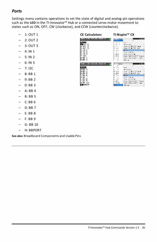
PortsSettings menu contains operations to set the state of digital and analog pin operationssuch as the LED in the TI-Innovator™ Hub or a connected servo motor movement tostates such as ON, OFF, CW (clockwise), and CCW (counterclockwise).
– 1: OUT 1– 2: OUT 2– 3: OUT 3– 4: IN 1– 5: IN 2– 6: IN 3– 7: I2C– 8: BB 1– 9: BB 2– 0: BB 3– A: BB 4– B: BB 5– C: BB 6– D: BB 7– E: BB 8– F: BB 9– G: BB 10– H: BBPORT
CE Calculators TI-Nspire™ CX
See also: Breadboard Components and Usable Pins
TI-Innovator™ Hub Commands Version 1.5 81

82 TI-Innovator™ Hub Commands Version 1.5
RANGEThe RANGE command is used with several analog input sensors to re-map the internalADC (Analog to Digital Converter) range of 0 to 16383 (14-bit ADC values) to a floatingpoint range specified as the parameters to this command, along with the sensor towhich the range is applied. The format for setting the range of a sensor is RANGEsensor [i] minimum maximum. To remove/reset to default the range from a givensensor, set the minimum and maximum value to zero. The minimum value must beless than the maximum value when setting a valid range.
A sensors current range, if present, can be obtained by READ sensor [i] RANGE. A two-element list of numbers in the form { minimum, maximum } will be returned.
Note: If no range has been applied to the sensor, an error will be returned if anattempt to read the sensor range is performed .
An individual sensors averaging value may be obtained by READ sensor [i] RANGE.
RANGE 'something' (for analog devices, maps ADC range from 0 to 16383 to the rangespecified, min < max, min, max any values.)
CE Calculators TI-Nspire™ CX
BRIGHTNESS minimum maximum
Command: BRIGHTNESS minimum maximum
Advanced user
CommandSyntax:
RANGE BRIGHTNESS minimummaximum
Range:
Describe: Changes/Sets themapping of ADC input values from theADC 0-16383 range to a user-selected range. The resulting sensor reading ismapped to this and a floating point result is returned. By default,the on-board BRIGHTNESS sensor is ranged to a 0-100 range.RANGE BRIGHTNESS minimummaximum
Result: Set mapping for on-board brightness/light sensor.
Type or Sensor

Command: BRIGHTNESS minimum maximum
Advanced user
AddressableComponent:
LOUDNESS i minimum maximum
Command: LOUDNESS i minimum maximum
Advanced user
CommandSyntax:
RANGE LOUDNESS iminimummaximum
Range:
Describe: Changes/Sets themapping of ADC input values from theADC 0-16383 range to a user-selected range. The resulting sensor reading ismapped to this and a floating point result is returned.RANGE LOUDNESS iminimummaximum
Result: Set mapping for sound-level analog sensor.
Type orAddressableComponent:
Sensor
LIGHTLEVEL i minimum maximum
Command: LIGHTLEVEL i minimum maximum
Advanced user
CommandSyntax:
RANGE LIGHTLEVEL iminimummaximum
Range: An integer value between 0 and 16383 (14bit resolution)
Describe: Changes/Sets themapping of ADC input values from theADC 0-16383 range to a user-selected range. The resulting sensor reading ismapped to this and a floating point result is returned.RANGE LIGHTLEVEL iminimummaximum
TI-Innovator™ Hub Commands Version 1.5 83

84 TI-Innovator™ Hub Commands Version 1.5
Command: LIGHTLEVEL i minimum maximum
Advanced user
Result: Set mapping for off-board light sensor (analog).
Type orAddressableComponent:
Sensor
TEMPERATURE i minimum maximum
Command: TEMPERATURE i minimum maximum
Advanced user
CommandSyntax:
RANGE TEMPERATURE iminimummaximum
Range:
Describe: .RANGE TEMPERATURE iminimummaximum
Result: Set mapping for soilmoisture analog sensor.
Type orAddressableComponent:
Sensor
POTENTIOMETER i minimum maximum
Command: POTENTIOMETER i minimum maximum
Advanced user
CommandSyntax:
RANGE POTENTIOMETER iminimummaximum
Range:
Describe: Changes/Sets themapping of ADC input values from theADC 0-16383 range to a user-selected range. The resulting sensor reading ismapped to this and a floating point result is returned. RANGE

Command: POTENTIOMETER i minimum maximum
Advanced user
POTENTIOMETER iminimummaximum
Result: Set mapping for rotary/linear potentiometers.
Type orAddressableComponent:
Sensor
MOISTURE i minimum maximum
Command: MOISTURE i minimum maximum
Advanced user
CommandSyntax:
RANGEMOISTURE iminimummaximum
Range: An integer value between 0 and 16383 (14bit resolution)
Describe: Changes/Sets themapping of ADC input values from theADC 0-16383 range to a user-selected range. The resulting sensor reading ismapped to this and a floating point result is returned.RANGEMOISTURE iminimummaximum
Result: Set mapping for soilmoisture analog sensor.
Type orAddressableComponent:
Sensor
THERMISTOR i minimum maximum
Command: THERMISTOR i minimum maximum
Advanced user
CommandSyntax:
RANGE THERMISTOR iminimummaximum
Range:
TI-Innovator™ Hub Commands Version 1.5 85

86 TI-Innovator™ Hub Commands Version 1.5
Command: THERMISTOR i minimum maximum
Advanced user
Describe: .RANGE THERMISTOR iminimummaximum
Result: Set mapping for xxxxxxxxxx.
Type orAddressableComponent:
Sensor
ANALOG.IN i minimum maximum
Command: ANALOG.IN i minimum maximum
Advanced user
CommandSyntax:
RANGE ANALOG.IN iminimummaximum
Range:
Describe: Changes/Sets themapping of ADC input values from theADC 0-16383 range to a user-selected range. The resulting sensor reading ismapped to this and a floating point result is returned.RANGE ANALOG.IN iminimummaximum
Result: Set mapping for generic analog input objects.
Type orAddressableComponent:
Sensor

AVERAGEThe AVERAGE command is used to set the number of ADC (Analog to Digital converter)samples taken to represent a single analog sensor reading. By default, the TI-Innovator™ Hub sets a global value of three (3) readings to be taken for a sensormeasurement. This is done to reduce variation due to noise etc. This default isadjustable between 1 and 25 by the SET AVERAGING n command. The current defaultcan be obtained by the READ AVERAGING command.
For individual sensors, the default can be changed after the CONNECT operation byusing the AVERAGE command. The format is AVERAGE sensor [i] value where sensor isa sensor from the table below, [i] is the index, if needed to identify the specific sensor,and value is a number from 1 to 25.
The sensor, when a sample is requested, will take value number of readings, 10microseconds apart, summing the readings together and averaging them over thenumber of readings taken.
An individual sensors averaging value may be obtained by READ sensor [i] AVERAGE.
AVERAGE 'something' (for analog devices, sets the individual oversampling value forreading, from 1 to 25)
Command: AVERAGE
CommandSyntax:
AVERAGE
Describe: Specifies the number of analog readings to take on a specific sensorto obtain a single reading of that sensor. Valid values are from 1 to25 readings, taken 10microseconds apart and averaged together.Sensors use the system default of 3 readings if not altered bychanging the system global setting via a SET AVERAGING command.
Result:
Type orAddressableComponent:
CE Calculators TI-Nspire™ CX
TI-Innovator™ Hub Commands Version 1.5 87

88 TI-Innovator™ Hub Commands Version 1.5
BRIGHTNESS n
Command: BRIGHTNESS n
CommandSyntax:
AVERAGE BRIGHTNESS n
Range: Where n ranges from 1 to 25
Describe: Set the number of readings from theADC to be used for the on-board light sensor.
Result: Set oversampling for on-board brightness/light sensor.
Type orAddressableComponent:
Sensor
LOUDNESS i n
Command: LOUDNESS i n
CommandSyntax:
AVERAGE LOUDNESS i n
Range: –where n ranges from 1 to 25
Describe: Set the number of readings from theADC to be used with anexternal sound loudness sensor.
Result: Set oversampling for sound-level analog sensor.
Type orAddressableComponent:
Sensor
LIGHTLEVEL i n
Command: LIGHTLEVEL i n
CommandSyntax:
AVERAGE LIGHTLEVEL i n
Range: –where n ranges from 1 to 25
Describe: Set the number of readings from theADC to be used for the

Command: LIGHTLEVEL i n
external light sensor connected to an analog input. Does notsupport I2C light sensors.
Result: Set oversampling for off-board light sensor (analog).
Type orAddressableComponent:
Sensor
TEMPERATURE i n
Command: TEMPERATURE i n
CommandSyntax:
AVERAGE TEMPERATURE i n
Range: Where n ranges from 1 to 25
Describe: Set the number of readings from theADC to be used for theexternal temperature sensor connected to an analog input. Doesnot support I2C or digital temperature sensors.
Result: When using an analog-style thermistor temperature sensor,oversample thismany times.
Type orAddressableComponent:
Sensor
POTENTIOMETER i n
Command: POTENTIOMETER i n
CommandSyntax:
AVERAGE POTENTIOMETER i n
Range: Where n ranges from 1 to 25
Describe: Set the number of readings from theADC to be used with anexternal potentiometer, either a linear or rotary model.
Result: Set oversampling for rotary/linear potentiometers.
Type orAddressable
Sensor
TI-Innovator™ Hub Commands Version 1.5 89

90 TI-Innovator™ Hub Commands Version 1.5
Command: POTENTIOMETER i n
Component:
MOISTURE i n
Command: MOISTURE i n
CommandSyntax:
AVERAGEMOISTURE i n
Range: –where n ranges from 1 to 25
Describe: Set the number of readings from theADC to be used with anexternalmoisture sensor.
Result: Set oversampling for soilmoisture analog sensor.
Type orAddressableComponent:
Sensor
THERMISTOR i n
Command: THERMISTOR i n
CommandSyntax:
AVERAGE THERMISTOR i n
Range: Where n ranges from 1 to 25
Describe: Set the number of readings from theADC to be used with anexternal thermistor connected to an analog input.
Result: Set oversampling for thermistor device analog input.
Type orAddressableComponent:
Sensor

ANALOG.IN i n
Command: ANALOG.IN i n
CommandSyntax:
AVERAGE ANALOG.IN i n
Range: Where n ranges from 1 to 25
Describe: Set the number of readings from theADC to be used for the analogsensor attached to this generic analog item.
Result: Sets oversampling count for generic analog input.
Type orAddressableComponent:
Sensor
PERIOD n
Command: PERIOD n
CommandSyntax:
PERIODn
Range:
Describe: TheAVERAGE command is somewhat unique for PERIOD in that itspecifies how many distinct periods are to bemeasured andaveraged together to obtain the desired measurement. Up to 25samplesmay be taken to obtain the period measurement for agiven pin.
Result: Set number of samples of frequency to take to be average togetherto generate period.
Type orAddressableComponent:
Sensor
TI-Innovator™ Hub Commands Version 1.5 91

92 TI-Innovator™ Hub Commands Version 1.5
DISCONNECT-OutputDISCONNECT breaks the association between a specified control or sensor and thepin/port it is associated with. If the specified sensor or control is not currentlyconnected to anything, an error is generated.
The DISCONNECT command does not generate an active response, other than possibleerror responses. Pins associated with an actively connected sensor, or control, arereleased from use and, in general, are set to a digital input state with no enabledpullup/pulldown.
DISCONNECT - disconnect something that has been connected, by index if needed.
Command: DISCONNECT-Output
CommandSyntax:
DISCONNECT
Range:
Describe: Removes the association of a sensor or controlwith a pin, or set ofpins, if such association exists.Places the pin(s) back to an OUTPUT state.
Result: .
Type orAddressableComponent:
CE Calculators TI-Nspire™ CX

LED i
Command: LED i
CommandSyntax:
DISCONNECT LED i
Range:
Describe: Disconnect an external LEDobject from the system.
Result: LED i is disconnected
Type orAddressableComponent:
Control
RGB i
Command: RGB i
CommandSyntax:
DISCONNECT RGB i
Range:
Describe: Disconnect an externalRGB LED from the system. These objects usethree hardware PWM signals to properly operate, so in the initialproduct release, the on-board COLOR object must be disconnectedto connect one of these objects.
Result: Disconnect RGB and free up PWM outputs for use elsewhere.
Type orAddressableComponent:
Control
SPEAKER i
Command: SPEAKER i
CommandSyntax:
DISCONNECT SPEAKER i
TI-Innovator™ Hub Commands Version 1.5 93

94 TI-Innovator™ Hub Commands Version 1.5
Command: SPEAKER i
Range:
Describe: Disconnect an external speaker from its digital pin.
Result: Disconnect a speaker from a digital output pin.
Type orAddressableComponent:
Control
POWER
Command: DISCONNECT POWER i
CommandSyntax:
DISCONNECT POWER 1
Range
Describe: This command removes the name POWER device from theprogram.
Result: The named POWER device cannot be used in the program after aDISCONNECT command.
Type orAddressableComponent:
Control
SERVO.CONTINUOUS i
Command: SERVO CONTINUOUS i
CommandSyntax:
DISCONNECT SERVO.CONTINUOUS i
CodeSample:
Range:
Describe: Disconnect a sweep or continuous SERVOmotor from the digitalpin associated with themotor.

Command: SERVO CONTINUOUS i
Result: Servo motor disconnected.
Type orAddressableComponent:
Control
ANALOG.OUT i
Command: ANALOG.OUT i
CommandSyntax:
DISCONNECT ANALOG.OUT i
Range:
Describe: Disconnects the connected generic analog output device specified,freeing a hardwaremap-able PWM if it is in usewith the object.
Result: Disconnect generic analog PWM output from pin.
Type orAddressableComponent:
Control
TI-Innovator™ Hub Commands Version 1.5 95

96 TI-Innovator™ Hub Commands Version 1.5
VIB.MOTOR
Command: VIB.MOTOR i [TO] PWM
CommandSyntax:
SET VIB.MOTOR i [TO] PWM
Range: PWM from 0 (none) and 255 (full on)
Describe: Vibration motor control interface.
Result: Vibrations : intensity is a value from 0 to 255.
Type orAddressableComponent:
Control
BUZZER i
Command: BUZZER i
CommandSyntax:
DISCONNECT BUZZER i
Range:
Describe: Disconnect an active buzzer from the system.Active buzzers play a tonewhen their signal is set high/on, and stopthe tonewhen the signal is dropped to ground.DISCONNECT BUZZER i
Result: ACTIVE buzzers disconnected from a digital pin.
Type orAddressableComponent:
Control
RELAY i
Command: RELAY i
CommandSyntax:
DISCONNECT RELAY i

Command: RELAY i
Range:
Describe: Disconnect a digital relay interface from the system.
Result: Relay disconnected.
Type orAddressableComponent:
Control
SERVO i
Command: SERVO i
CommandSyntax:
DISCONNECT SERVO i
CodeSample:
Range:
Describe: Disconnect a sweep or continuous SERVOmotor from the digitalpin associated with themotor.
Result: Servo motor disconnected.
Type orAddressableComponent:
Control
SQUAREWAVE i
Command: SQUAREWAVE i
CommandSyntax:
DISCONNECT SQUAREWAVE i
Range:
Describe: Disconnect the software generated squarewave generator from anassociated digital output pin. The pin reverts to digital input upon
TI-Innovator™ Hub Commands Version 1.5 97

98 TI-Innovator™ Hub Commands Version 1.5
Command: SQUAREWAVE i
disconnect.
Result: Disconnect squarewave function from pin(s), stops squarewavegeneration.
Type orAddressableComponent:
Control
DIGITAL.OUT i
Command: DIGITAL.OUT i
CommandSyntax:
DISCONNECT DIGITAL.OUT i
Range:
Describe: Disconnect a generic DIGITAL object. The associated pin is revertedto a digital INPUT pin with no enabled pullup or pulldown. TheDIGITAL object number can be used to refer the samepin in eitherinput, or output form...
Result: Disconnect digital input object.
Type orAddressableComponent:
Control/Sensor

BBPORT
Command: DISCONNECT BBPORT
CommandSyntax:
DISCONNECT BBPORT
Range
Describe: Disconnects all connected BBPORT object pins, and resets thosepins to the default INPUT state, and unused/available for other use.
Result: TheBBPORT object is no longer available for use in the program.
Type orAddressableComponent:
Control/Sensor
LIGHT
Command: LIGHT
CommandSyntax:
DISCONNECT LIGHT
Range:
Describe: Disconnect the on-board RED LEDused for direct program controlfrom the system.
Result: On-board LEDdisconnected
Type orAddressableComponent:
Control
COLOR
Command: COLOR
CommandSyntax:
DISCONNECT COLOR
Range:
Describe: Disconnects the on-board RGB LED item from use. This action (in the
TI-Innovator™ Hub Commands Version 1.5 99
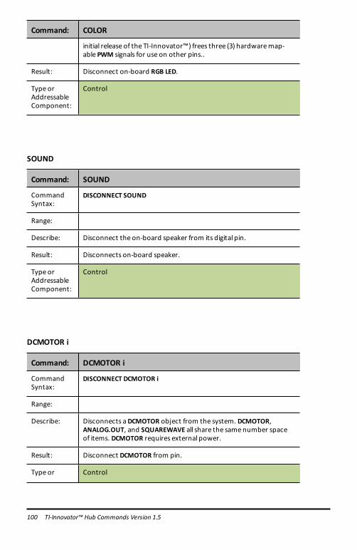
100 TI-Innovator™ Hub Commands Version 1.5
Command: COLOR
initial release of the TI-Innovator™) frees three (3) hardwaremap-able PWM signals for use on other pins..
Result: Disconnect on-board RGB LED.
Type orAddressableComponent:
Control
SOUND
Command: SOUND
CommandSyntax:
DISCONNECT SOUND
Range:
Describe: Disconnect the on-board speaker from its digital pin.
Result: Disconnects on-board speaker.
Type orAddressableComponent:
Control
DCMOTOR i
Command: DCMOTOR i
CommandSyntax:
DISCONNECT DCMOTOR i
Range:
Describe: Disconnects aDCMOTOR object from the system. DCMOTOR,ANALOG.OUT, and SQUAREWAVE all share the samenumber spaceof items. DCMOTOR requires external power.
Result: Disconnect DCMOTOR from pin.
Type or Control

Command: DCMOTOR i
AddressableComponent:
TI-Innovator™ Hub Commands Version 1.5 101

102 TI-Innovator™ Hub Commands Version 1.5
DISCONNECT-InputDISCONNECT breaks the association between a specified control or sensor and thepin/port it is associated with. If the specified sensor or control is not currentlyconnected to anything, an error is generated.
The DISCONNECT command does not generate an active response, other than possibleerror responses. Pins associated with an actively connected sensor, or control, arereleased from use and, in general, are set to a digital input state with no enabledpullup/pulldown.
DISCONNECT - disconnect something that has been connected, by index if needed.
Command: DISCONNECT-Input...
CommandSyntax:
DISCONNECT
Range:
Describe: Removes the association of a sensor or controlwith a pin, or set ofpins, if such association exists. Places the pin(s) back to an INPUTstate.
Result: .
Type orAddressableComponent:
CE Calculators TI-Nspire™ CX
DHT i
Command: DHT i
Command DISCONNECT DHT i

Command: DHT i
Syntax:
Range: Temperature reading default is in CelsiusHumidity reading from 0 to 100%
Describe: Disconnects the specified digital humidity DHT and temperaturesensor from the system. This also removes that object from theperiod scan list of style sensors in theDHT task.
Result: Digital humidity/temperature sensor(s) disconnected.
Type orAddressableComponent:
Sensor
RANGER i
Command: RANGER i
CommandSyntax:
DISCONNECT RANGER i
Range:
Describe: Disconnect a digital ultrasonic ranging sensor from the two digitalpins it uses.
Result: Ultrasonic ranging sensor disconnected.
Type orAddressableComponent:
Sensor
LIGHTLEVEL i
Command: LIGHTLEVEL i
CommandSyntax:
DISCONNECT LIGHTLEVEL i
Range:
Describe: Disconnect an external light sensor.
TI-Innovator™ Hub Commands Version 1.5 103

104 TI-Innovator™ Hub Commands Version 1.5
Command: LIGHTLEVEL i
Result: Light sensor disconnected.
Type orAddressableComponent:
Sensor
TEMPERATURE i
Command: TEMPERATURE i
CommandSyntax:
DISCONNECT TEMPERATURE i
Range: Temperature reading default is in Celsius. The range depends on thespecific temperature sensor being used.Humidity reading from 0 to 100%
Describe: Disconnect a connected temperature sensor from the system.TEMPERATURE sensors can be either analog (thermistor-style).Disconnecting from the analog or digital reverts the associated pinsto INPUT.
Result: Disconnect temperature sensor.
Type orAddressableComponent:
Sensor
MOISTURE i
Command: MOISTURE i
CommandSyntax:
DISCONNECTMOISTURE i
Range:
Describe: Disconnect an analogmoisture sensor.
Result: Disconnect analogmoisture sensors
Type orAddressableComponent:
Sensor

MAGNETIC
Command: DISCONNECT MAGNETIC i
CommandSyntax:
DISCONNECTMAGNETIC 1
Range
Describe: TheMAGNETIC sensor is used to detect the presence of amagneticfield. It uses theHall effect. It is also known as a Hall effect sensor.
TheDISCONNECT command removes the sensor from the program.
Result: The name “MAGNETIC 1” is now disconnected from the sensor. Itcannot be used in the program after aDISCONNECT command.
Type orAddressableComponent:
Sensor
VERNIER
Command: DISCONNECT VERNIER i
CommandSyntax:
DISCONNECT VERNIER 1
Range
Describe: This command removes the named Vernier device from theprogram.
Result: A Vernier analog sensor connected to the TI-Innovator™ Hubthrough a TI-SensorLink cannot be used in the program after aDISCONNECT command.
Type orAddressableComponent:
Sensor
TI-Innovator™ Hub Commands Version 1.5 105

106 TI-Innovator™ Hub Commands Version 1.5
ANALOG.IN i
Command: ANALOG.IN i
CommandSyntax:
DISCONNECT ANALOG.IN i
Range:
Describe: Disconnects the connected generic analog input device specified.
Result: Disconnect generic analog input from pin.
Type orAddressableComponent:
Sensor
DIGITAL.IN i
Command: DIGITAL.IN i
CommandSyntax:
DISCONNECT DIGITAL.IN i
Range:
Describe: Disconnect a generic DIGITAL object. The associated pin is revertedto a digital INPUT pin with no enabled pullup or pulldown. TheDIGITAL object number can be used to refer the samepin in eitherinput, or output form.
Result: Disconnect digital input object.
Type orAddressableComponent:
Control/Sensor
SWITCH
Command: SWITCH
CommandSyntax:
DISCONNECT SWITCH i
Range:
Describe: Disconnect a switch from its digital pin. The pin reverts to INPUT

Command: SWITCH
state, and the switch is removed from the scanning sequence in theBUTTON task.
Result: disconnect switch object from pin
Type orAddressableComponent:
Sensor
BUTTON i
Command: BUTTON i
CommandSyntax:
DISCONNECT BUTTON i
Range:
Describe: Disconnects the specified button object from the system andremoves it from the list of scanned buttons/switches in theBUTTONtask.
Result: Digital button/switch is disconnected.
Type orAddressableComponent:
Sensor
MOTION i
Command: MOTION i
CommandSyntax:
DISCONNECTMOTION i
Range:
Describe: Disconnects a digitalPIR (passive infrared)MOTION detector andremoves the object from the scanning list in theBUTTON task.
Result: Disconnect passive I/Rmotion detectors
Type or Sensor
TI-Innovator™ Hub Commands Version 1.5 107

108 TI-Innovator™ Hub Commands Version 1.5
Command: MOTION i
AddressableComponent:
POTENTIOMETER i
Command: POTENTIOMETER i
CommandSyntax:
DISCONNECT POTENTIOMETER i
Range:
Describe: Disconnect an analog variable resistor (POTENTIOMETER) from thesystem
Result: Disconnect a rotary/linear potentiometer sensors
Type orAddressableComponent:
Sensor
THERMISTOR i
Command: THERMISTOR i
CommandSyntax:
DISCONNECT THERMISTOR i
Range:
Describe: Disconnect an analog thermistor sensor from the associated pin.
Result: disconnect analog thermistor
Type orAddressableComponent:
Sensor

RGB
Command: DISCONNECT RGB
CommandSyntax:
DISCONNECT RGB
Range
Describe: TheDISCONNECT command removes the TI-RGB Array from theprogram.
Result: The TI-RGB Array cannot be used in the program after aDISCONNECT command.
Type orAddressableComponent:
Sensor
LOUDNESS i
Command: LOUDNESS i
CommandSyntax:
DISCONNECT LOUDNESS i
Range:
Describe: Disconnect an analog sound intensity (LOUDNESS) sensor.
Result: Analog sound level sensor disconnected
Type orAddressableComponent:
Sensor
TI-Innovator™ Hub Commands Version 1.5 109

110 TI-Innovator™ Hub Commands Version 1.5
BBPORT
Command: DISCONNECT BBPORT
CommandSyntax:
DISCONNECT BBPORT
Range
Describe: Disconnects all connected BBPORT object pins, and resets thosepins to the default INPUT state, and unused/available for other use.
Result: TheBBPORT object is no longer available for use in the program.
Type orAddressableComponent:
Control/Sensor
BRIGHTNESS
Command: BRIGHTNESS
CommandSyntax:
DISCONNECT BRIGHTNESS
Range:
Describe: Disconnects the internal connection to the on-board BRIGHTNESS(light sensor) object.
Result: Disconnect on-board LIGHT sensor.
Type orAddressableComponent:
Sensor

MANAGEThe Manage menu pastes a Send( command with the following management items.
Str0 is displayed on Home Screen with information if requested in the command.
CE Calculators TI-Nspire™ CX
BEGINThe BEGIN command disconnects all connected sensors and controls, re-initializes allsensor/control memory within the sketch, and resets the sensor average default value,error formatting, and flow control defaults. Additionally, all INn port pins, and thebreadboard connector (BBn) pins are set to the INPUT pin mode. All OUTn port pins areset to the INPUT state, and allowed to float, including OUT3 which will read as highdue to a pullup resistor from the 5V supply on this pin.
When the entire process completes, a response of READY is sent to the host system. This response must be waited for by the host before any further operations areperformed. Additional commands may be in the command queue to be executed, butwill not be acted upon until this command completes.
BEGIN
Command: BEGIN
CommandSyntax:
SEND("BEGIN"
Describe: Disassociates sensors from ports or pins, and resets all settings backto defaults.Disconnects any connected sensor objects and restores system tostate as if RESET button pressed.
Result: Respondswith a "READY"when completed.
Type orAddressableComponent:
Not Applicable
TI-Innovator™ Hub Commands Version 1.5 111

112 TI-Innovator™ Hub Commands Version 1.5
Note: The [ : ] is used to sequence command lines on one command line. The Manage…menu pastes a convenient set of commands to then display the information in Str0 onthe home screen.
ISTIThe ISTI command is used to synchronize communications with the sketch. Theresponse to this command must be TISTEM. Responses may have a leading NUL (0)character on initial power-on of the Innovator hub. All responses from the Innovatorhub will be followed with a CR/LF pair that may or may not be stripped by softwarelayers in the host system prior to the response being received by the application layeron the host system.
ISTI
Command: ISTI
CommandSyntax:
ISTI
Describe: Send "ISTI", and get response "TISTEM".
Result: Handshake command used to determine presence of a supported“sketch”on the TI-Innovaotr™ Hub.
Type orAddressableComponent:
WHOWHO is an identification command (similar to the ISTI handshake command below)that can be used to determine what product is present and running the sketch.
The correct response toWHO is "TI INNOVATOR ON MSP432" when this command issent to the TI-Innovator Hub.
WHO
Command: WHO
CommandSyntax:
WHO
Describe: Identification command to determinewhat product is running thesketch.Send ("WHO")Get Str0Disp Str0
Result: Identify the product - TI INNOVATOR ONMSP432.

Command: WHO
Type orAddressableComponent:
WHATThe WHAT command is an identification command. The response toWHAT for TI-Innovator is "TI INNOVATOR HUB".
WHAT
Command: WHAT
CommandSyntax:
WHAT
Describe: Product namequery.Identify the product - "TI INNOVATOR HUB"Send ("WHAT")Get Str0Disp Str0
Result: Identify the product.
Type orAddressableComponent:
HELPHELP is used to obtain quick information about each of these commands. The HELPcommand-name is sent, and generates a string response with a one-line description ofthe given command.
HELP
Command: HELP
CommandSyntax:
HELP
Describe: Provides per command quick help information. i.e. HELP SET, etc.
Result:
Type orAddressableComponent:
TI-Innovator™ Hub Commands Version 1.5 113
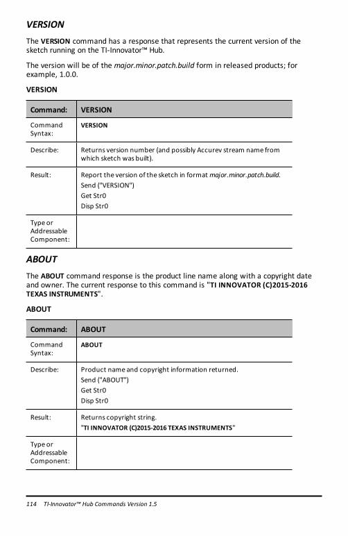
114 TI-Innovator™ Hub Commands Version 1.5
VERSIONThe VERSION command has a response that represents the current version of thesketch running on the TI-Innovator™ Hub.
The version will be of the major.minor.patch.build form in released products; forexample, 1.0.0.
VERSION
Command: VERSION
CommandSyntax:
VERSION
Describe: Returns version number (and possibly Accurev stream name fromwhich sketch was built).
Result: Report the version of the sketch in format major.minor.patch.build.Send ("VERSION")Get Str0Disp Str0
Type orAddressableComponent:
ABOUTThe ABOUT command response is the product line name along with a copyright dateand owner. The current response to this command is "TI INNOVATOR (C)2015-2016TEXAS INSTRUMENTS".
ABOUT
Command: ABOUT
CommandSyntax:
ABOUT
Describe: Product name and copyright information returned.Send ("ABOUT")Get Str0Disp Str0
Result: Returns copyright string."TI INNOVATOR (C)2015-2016 TEXAS INSTRUMENTS"
Type orAddressableComponent:

COLLECTUse the COLLECT and READ LIST commands to:
- Collect up to 10 samples per second- From up to 4 sensors (the Digital Humidity and Temperature – DHT – sensor
counts as 2 sensors)- The sensors can be a mix of Vernier sensors (through TI Sensor Link) and Seeed
sensors
Note:
- Data is collected through programs in TI-Basic and Python- Data can be saved in lists- No integration with Vernier DataQuest (TI-Nspire™ CX) & EzData (TI-8x CE
family)
COLLECT
Command: COLLECT <sensor1> AND <sensor2> TIME t RATE r
CommandSyntax:
COLLECT <sensor1> AND<sensor2> TIME t RATE r
Defaultvalue:
Default value of for TIME: 10 secondsDefault value of rate: 4 (samples/second)
Range: Maximum 4 sensorsRange for TIME: 1 - 100 (seconds)Range for RATE: 1 - 10 (samples per second)
CodeSample:
TI-Nspire™:Send "CONNECT TEMPERATURE 1 TO IN 1"
Send "COLLECT TEMPERATURE 1 TIME 5 RATE 4"
Wait 6
Send "READ LIST TEMPERATURE 1"
Get listtemp
Send "READ LIST TIME"
Get listtime
CodeSample:
CE family:Send("COLLECT BRIGHTNESS RATE 5 TIME 5")
Wait 6
Send("READ LIST BRIGHTNESS")
Get(L₁)
Send("READ LIST TIME")
Get(L₂)
TI-Innovator™ Hub Commands Version 1.5 115

116 TI-Innovator™ Hub Commands Version 1.5
Command: COLLECT <sensor1> AND <sensor2> TIME t RATE r
Disp L₁
Disp L₂
Describe:
Result: The "READ LIST TIME" command will return the sample timescorresponding to the sensor sample values.Each "READ LIST" command returns amaximum of 64data points.For collections that exceed 64 samples, the program will have to usethe "READ LIST" command multiple times and combine the resultinglists.
Type orAddressableComponent:
This command can be used with most sensors.It cannot be used with many I2C sensors or theRV.COLORINPUTand RV.GYRO sensors built-in to TI-Innovator™ Rover.This command willwork with theRV.RANGER sensor.
For collections that exceed 64 samples, the program will have to use the “READ LIST”command multiple times and combine the resulting lists.
Example:
1. This TI-Nspire™ program will collect 10 samples per second from a temperaturesensor for 10 seconds – a total of 101 samples.
CodeSample:
Send "CONNECT TEMPERATURE 1 TO IN 1"
Send "COLLECT TEMPERATURE 1 TIME 10 RATE 10"
Wait 11
Send "READ LIST TEMPERATURE 1"
Get readbuffer
listtemp1:=readbuffer
While dim(readbuffer)=64
••Send "READ LIST TEMPERATURE 1"
••Wait 0.2
••Get readbuffer
••listtemp1:=augment(listtemp1,readbuffer)EndWhile
Send "READ LIST TIME"
Get readbuffer listtime:=readbuffer
While dim(readbuffer)=64
••Send "READ LIST TIME"
••Wait 0.2
••Get readbuffer
••listtime:=augment(listtime,readbuffer)EndWhile

The ‘Wait 0.2’ command between the ‘Send’ and the ‘Get’ commands is needed toensure that all of the data makes it to the program before the next batch is read.
This delay is only needed on the TI-Nspire™ CX and TI-Nspire™ CX II handhelds.
2. This CE program collects 8 samples per second for 10 seconds from the built-inBRIGHTNESS sensor. The total number of samples will be 81 so the program will haveto use READ LIST twice to get all the samples and then combine the lists.
CodeSample:
Send("COLLECT BRIGHTNESS RATE 8 TIME 10")
Wait 11
Send("READ LIST BRIGHTNESS")
Get(L₁)
Send("READ LIST BRIGHTNESS")
Get(L₂)
Send("READ LIST TIME")
Get(L₃)
Send("READ LIST TIME")
Get(L₄)
augment(L₁,L₂)→L₁
augment(L₃,L₄)→L₃
Disp dim(L₁)
Disp dim(L₃)
Disp L₁
Disp L₃
3. This TI-Nspire™ program collects samples from 2 sensors.
CodeSample:
Send "CONNECT DHT1 TO IN 1"
Send "CONNECT VERNIER 1 TO IN 2 AS PRESSURE"
Send "COLLECT DHT 1 AND VERNIER 1 TIME 10 RATE 4"
@ This will collect 41 samples for each sensorWAIT 10
Send "READ LIST DHT1 TEMPERATURE"
Get list1
Send "READ LIST DHT1 HUMIDITY"
Get list2
Send "READ LIST VERNIER 1"
Get list3
Send "READ LIST TIME"
Get list4
Note:
1. The COLLECT command cannot be used for some RV sensors like RV.GYRO orRV.COLORINPUT. It will work with RV.RANGER
TI-Innovator™ Hub Commands Version 1.5 117

118 TI-Innovator™ Hub Commands Version 1.5
It can be used with sensors connected to the Hub while the Hub is in TI-Innovator™Rover.
2. The data collection starts as soon as the command is processed.
3. If a READ LIST command is issued during an active collection, an error is indicated.
4. Other SET & READ commands can be processed while a COLLECT is in progress aslong as the READ command doesn’t use a sensor that’s part of the COLLECTcommand.
5. The AVERAGING command will affect the data collected with a COLLECT commandonly if it is issued before the CONNECT commands. See the documentation for theAVERAGING command.
READ COLLECT
Command: READ COLLECT
CommandSyntax:
READCOLLECT
Defaultvalue:
Range:
Describe:
Result: Returns:0 - no active collection in progress1 - active collection in progress
Type orAddressableComponent:
This command can be used with most sensors.It cannot be used with many I2C sensors or theRV.COLORINPUTand RV.GYRO sensors built-in to TI-Innovator™ Rover.This command willwork with theRV.RANGER sensor.
Note:
1. The COLLECT command cannot be used for some RV sensors like RV.GYRO orRV.COLORINPUT. It will work with RV.RANGER
It can be used with sensors connected to the Hub while the Hub is in TI-Innovator™Rover.
2. The data collection starts as soon as the command is processed.
3. If a READ LIST command is issued during an active collection, an error is indicated.
4. Other SET & READ commands can be processed while a COLLECT is in progress aslong as the READ command doesn’t use a sensor that’s part of the COLLECTcommand.

5. The AVERAGING command will affect the data collected with a COLLECT commandonly if it is issued before the CONNECT commands. See the documentation for theAVERAGING command.
TI-Innovator™ Hub Commands Version 1.5 119

120 TI-Innovator™ Hub Commands Version 1.5
Additional Supported CommandsThe following sets of supported commands are not found in the Hub Menus.
Additional SET Commands
FORMAT ERROR STRING/NUMBER
Command: FORMAT ERROR STRING/NUMBER
Advanced user
CommandSyntax:
SET FORMAT ERROR STRING/NUMBER
Range:
Describe: Used for setting error return format and optional audible tone onerror.SET FORMAT ERROR STRING/NUMBER – returned error codes instring or numeric format.
Result: Sets the format for the return of error information (numbers, orstrings).
Type orAddressableComponent:
Setting
FORMAT ERROR NOTE/QUIET
Command: FORMAT ERROR NOTE/QUIET
Advanced user
CommandSyntax:
SET FORMAT ERROR NOTE/QUIET
Range:
Describe: Used for setting error return format and optional audible tone onerror.

Command: FORMAT ERROR NOTE/QUIET
Advanced user
SET FORMAT ERROR NOTE/QUIET – error display flash accompaniedby speaker sound or no sound.
Result: Enables tones, or disables tones in addition to the string/numberreporting above.
Type orAddressableComponent:
Setting
FLOW [TO] ON/OFF
Command: FLOW [TO] ON/OFF
Advanced user
CommandSyntax:
SET FLOW [TO]ON/OFF
Range:
Describe: Enables (ON) or disables (OFF) the software flow controlmechanismbetween the sketch and the communications hardware.NOTE:When the SEGDISPmodule is CONNECTed, this settingdetermineswhether or not the display module shows errorinformation (flow control disabled), or command queue depth(flow control enabled).
Result: Turn on xon/xoff flow control, or turn off (no flow control)
Type orAddressableComponent:
Setting
TI-Innovator™ Hub Commands Version 1.5 121

122 TI-Innovator™ Hub Commands Version 1.5
OUT1/2/3 [TO]
Command: OUT1/2/3 [TO]
CommandSyntax:
OUT1/2/3 [TO] ...SET OUTn0-255SET OUTnHIGH/ONSET OUTn LOW/OFF
Range: Set analog PWMvalue on OUT port(s) of the TI-Innovator™Hub
Describe: Direct output of information to a given output port. These arePWMoutputs on the TI-Innovator™ Hub.Set analog PWMvalue on TI-Innovator™ Hub OUT port(s).
SET OUTn0-255 – 0=off, 255=on, anything else is a PWM signal@ 500Hzwith duty cycle high from 1 to 254, where that range provides apercentage of the high-time signal of thewaveform.SET OUTnHIGH/ON – same as 255SET OUTn LOW/OFF – same as 0
Result: Set analog PWM value on OUT port(s) of the TI-Innovator™ Hub
Type orAddressableComponent:
Port

Additional READ Commands
BUZZER i
Command: BUZZER i
CommandSyntax:
READBUZZER i
Range:
Describe: Returns the current state of the active buzzer specified; 0 = silent, 1 =playing tone.
Result: Returns state of active buzzer, 0=silent, 1=on
Type orAddressableComponent:
Control
COLOR
Command: COLOR
CommandSyntax:
READCOLOR
Range:
Describe: Read the current output state of the on-board COLOR RGB LEDwithsub-components .RED, .GREEN, .BLUE. When reading the entireitem, a list of three values is returned, with values between 0 and255where 0=off, 255=full on, and values in between indicate PWMlevels.READCOLOR – returns list of 3 values representing { red, green, blue }PWM levelsREADCOLOR.REDREADCOLOR.GREENREADCOLOR.BLUESeeAlso: RGB i
TI-Innovator™ Hub Commands Version 1.5 123

124 TI-Innovator™ Hub Commands Version 1.5
Command: COLOR
Result: Returns list of 3 values representing { red, green, blue } PWM levels.Returns RED/GREEN/BLUE values for on-board RGB (color) LED.
Type orAddressableComponent:
Control
COLOR.RED
Command: COLOR RED
CommandSyntax:
READCOLOR.RED
Range:
Describe: Read the current output state of the on-board COLOR RGB LEDwithsub-components .RED, .GREEN, .BLUE. When reading the entireitem, a list of three values is returned, with values between 0 and255where 0=off, 255=full on, and values in between indicate PWMlevels.READCOLOR.RED
Result: Returns values representing {red} PWM levels.Returns RED values for on-board RGB (color) LED.
Type orAddressableComponent:
Control
COLOR.GREEN
Command: COLOR GREEN
CommandSyntax:
READCOLOR.GREEN

Command: COLOR GREEN
Range:
Describe: Read the current output state of the on-board COLOR RGB LEDwithsub-components .RED, .GREEN, .BLUE. When reading the entireitem, a list of three values is returned, with values between 0 and255where 0=off, 255=full on, and values in between indicate PWMlevels.READCOLOR.GREEN
Result: Returns list of 3 values representing { red, green, blue } PWM levels.Returns RED/GREEN/BLUE values for on-board RGB (color) LED.
Type orAddressableComponent:
Control
COLOR.BLUE
Command: COLOR BLUE
CommandSyntax:
READCOLOR.BLUE
Range:
Describe: Read the current output state of the on-board COLOR RGB LEDwithsub-components .RED, .GREEN, .BLUE. When reading the entireitem, a list of three values is returned, with values between 0 and255where 0=off, 255=full on, and values in between indicate PWMlevels.READCOLOR.BLUE
Result: Returns list of 3 values representing { red, green, blue } PWM levels.Returns RED/GREEN/BLUE values for on-board RGB (color) LED.
Type orAddressableComponent:
Control
TI-Innovator™ Hub Commands Version 1.5 125

126 TI-Innovator™ Hub Commands Version 1.5
DCMOTOR i
Command: DCMOTOR i
CommandSyntax:
READDCMOTOR i
Range:
Describe: Motor that converts direct current electrical power intomechanical power.
Result: Returnswhether dcmotor is running (1) or stopped (0).
Type orAddressableComponent:
Control
DIGITAL.OUT i
Command: DIGITAL.OUT i
CommandSyntax:
READDIGITAL.OUT i
Range:
Describe: Returns the current state of the digital pin connected to theDIGITALobject, or the cached state of the digital output value lastSET to the object.
Result: Return 0 (output low), 1 (output high).
Type orAddressableComponent:
Control/Sensor

FORMAT
Command: FORMAT
Advanced user
CommandSyntax:
READ FORMAT
Range:
Describe: Return the current formatting flags for error reporting. The valuereturned is a byte value indicating various flags. Masking with valuesindicates what error reporting options are active.1 = ERROR strings reported2 = ERROR numbers reported+4 = ERROR TONE enabled, if not set, errors are reported silently.
Result: Read error format (1=strings, 2=numbers, +4 to either: tonesenabled).
Type orAddressableComponent:
Setting
FLOW
Command: FLOW
Advanced user
CommandSyntax:
READ FLOW
Range:
Describe: Returns the current flow control setting; 0=disabled, 1=enabled.
Result: Read current flow control, 0 = none, 1 = xon/xoff
Type orAddressableComponent:
Setting
TI-Innovator™ Hub Commands Version 1.5 127

128 TI-Innovator™ Hub Commands Version 1.5
IN1/IN2/IN3
Command: IN1/IN2/IN3
CommandSyntax:
READ IN1READ IN2READ IN3
Range:
Describe: Read the value present on the indicated port, and return that valueto the host.
Result: Read value of analog port on TI STEMboard
Type orAddressableComponent:
Port
LAST ERROR
Command: LAST ERROR
CommandSyntax:
READ LAST ERROR
Range:
Describe: Returns the last reported error from the last operation. Dependingon the FORMAT ERROR setting, the responsemay be a STRINGor aNUMBER.
Result: Return last encountered error, resets automatically to 0, no error.
Type orAddressableComponent:
Setting

LED i
Command: LED i
CommandSyntax:
READ LED i
Range:
Describe: Read the current state of the specified LED. If the LED is digital, a 0 or1 is returned indicating the LED is off or on. If the LED is connected toa PWM output, a value from 0 to 255will be returned, indicating thecurrent PWM levelwhere 0 is off, 255 is full on, and values inbetween indicate the current PWM setting.
Result: Get state of LED, 0 or 1 if digital, 0-255 if PWM on analog.
Type orAddressableComponent:
Control
LIGHT
Command: LIGHT
CommandSyntax:
READ LIGHT
Range:
Describe: Returns the state of the on-board RED LED (digital only). A value of 0is off, and 1 is on.
Result: Get current state of on-board red LED (0=off, 1=on).
Type orAddressableComponent:
Control
TI-Innovator™ Hub Commands Version 1.5 129

130 TI-Innovator™ Hub Commands Version 1.5
OUT1/2/3
Command: OUT1/2/3
CommandSyntax:
READOUT1READOUT2READOUT3
Range:
Describe: Read value of current port as input (may be a digital read since thesedo not support analog-input.READOUT1/OUT2/OUT3
Result: Read value of analog port on TI STEM board.
Type orAddressableComponent:
Port
PWR
Command: PWR
CommandSyntax:
READPWR
Range:
Describe: Returns the current state of presence of external power connectedto the PWR port. The PWR port is read, and a status value of 0 (notpresent) or 1 (present) is returned, based on whether or notexternal power is available.READPWR
Result: Returns state of external power presence on PWR port (0=notpresent, 1=ext pwr present).
Type orAddressableComponent:
Status

RELAY i
Command: RELAY i
CommandSyntax:
READRELAY i
Range:
Describe: Return the current state of the specified relay. 0 =OFF, 1 =ON.
Result: Read state of relay - 0=not active 1=active.
Type orAddressableComponent:
Control
RESOLUTION
Command: RESOLUTION
CommandSyntax:
READRESOLUTION
Range:
Describe: Returns the bit resolution used by the system for ADC readings.
Result: Returns ADC resolution in use, in bits (default is 14).
Type orAddressableComponent:
Setting
RGB i
Command: RGB i
Command READRGB i
TI-Innovator™ Hub Commands Version 1.5 131

132 TI-Innovator™ Hub Commands Version 1.5
Command: RGB i
Syntax:
Range:
Describe: Same as the COLOR object referenced above, and has sub-objectsnamed RED, GREEN, and BLUE. This command returns the currentPWM level that the specified object is using.READRGB i– returns a 3 element list, consisting of the { red, green,blue } color level.READRED i– returns just the current red-component level.READGREEN iREADBLUE i
Result: Get state of RGB LED, {r,g,b} list values
Type orAddressableComponent:
Control
RED i
Command: RED i
CommandSyntax:
READRED i
Range:
Describe: Same as the COLOR object referenced above, and has sub-objectsnamed RED, GREEN, and BLUE. This command returns the currentPWM level that the specified object is using.READRGB i– returns a 3 element list, consisting of the { red, green,blue } color level.READRED i– returns just the current red-component level.
Result: Get state of RGB RED component.
Type orAddressableComponent:
Control

GREEN i
Command: GREEN i
CommandSyntax:
READGREEN i
Range:
Describe: Same as the COLOR object referenced above, and has sub-objectsnamed RED, GREEN, and BLUE. This command returns the currentPWM level that the specified object is using.READRGB i– returns a 3 element list, consisting of the { red, green,blue } color level.READGREEN i– returns just the current green-component level.
Result: Get state of RGB GREEN component.
Type orAddressableComponent:
Control
BLUE i
Command: BLUE i
CommandSyntax:
READBLUE i
Range:
Describe: Same as the COLOR object referenced above, and has sub-objectsnamed RED, GREEN, and BLUE. This command returns the currentPWM level that the specified object is using.READRGB i– returns a 3 element list, consisting of the { red, green,blue } color level.READBLUE i– returns just the current blue-component level
Result: Get state of RGB BLUE component.
Type orAddressableComponent:
Control
TI-Innovator™ Hub Commands Version 1.5 133

134 TI-Innovator™ Hub Commands Version 1.5
SERVO i
Command: SERVO i
CommandSyntax:
READSERVO i
Range:
Describe: Returns the current position of a sweep servo in the range -90 to 90,OR the current speed of rotation of a continuous servo motor.Additionally, the current “calibration” setting for the servo whichconsists of a 2-element list representing the lower and uppermicrosecond pulsewidths corresponding to the sweep/rotationrangesmay be read.READSERVO i– get current sweep position or rotationspeed/direction.READSERVO i CALIBRATION – get current microsecond range forsweep or rotation.
Result: Return current servo position in degrees from -90 to +90.
Type orAddressableComponent:
Control
SERVO i CALIBRATION
Command: SERVO i CALIBRATIONAdvanced user
CommandSyntax:
READSERVO i CALIBRATION
Range:
Describe: Returns the current position of a sweep servo in the range -90 to 90,OR the current speed of rotation of a continuous servo motor.Additionally, the current “calibration” setting for the servo whichconsists of a 2-element list representing the lower and uppermicrosecond pulsewidths corresponding to the sweep/rotationrangesmay be read.READSERVO i CALIBRATION – get current microsecond range forsweep or rotation.

Command: SERVO i CALIBRATIONAdvanced user
Result: Return current servo position in degrees from -90 to +90.
Type orAddressableComponent:
Control
SOUND
Command: SOUND
CommandSyntax:
READSOUND
Range:
Describe: Returns a value indicating whether sound is currently being played(1) or not (0) through the on-board speaker.
Result: Return whether on-board speaker is playing a tone (1) or is silent(0).
Type orAddressableComponent:
Control
SPEAKER i
Command: SPEAKER i
CommandSyntax:
READSPEAKER i
Range:
Describe: Returns a value indicating whether sound is currently being played(1) or not (0) through an external speaker.
TI-Innovator™ Hub Commands Version 1.5 135

136 TI-Innovator™ Hub Commands Version 1.5
Command: SPEAKER i
Result: Return whether speaker is playing a tone (1) or silent (0).
Type orAddressableComponent:
Control
SQUAREWAVE i
Command: SQUAREWAVE i
CommandSyntax:
READSQUAREWAVE i
Range:
Describe: Returns a 0 the current squarewave object is not active. A value of 1is returned if the object is actively generating an output.
Result: Returnswhether squarewave is active (1) or not active (0).
Type orAddressableComponent:
Control

Additional AVERAGE Commands
PERIOD n
Command: PERIOD n
CommandSyntax:
PERIODn
Range:
Describe: TheAVERAGE command is somewhat unique for PERIOD in that itspecifies how many distinct periods are to bemeasured andaveraged together to obtain the desired measurement. Up to 25samplesmay be taken to obtain the period measurement for agiven pin.
Result: Set number of samples of frequency to take to be average togetherto generate period.
Type orAddressableComponent:
Sensor
TI-Innovator™ Hub Commands Version 1.5 137

138 TI-Innovator™ Hub Commands Version 1.5
Additional CALIBRATION Commands
CALIBRATE
CALIBRATE is used to set various sensor and control values that do not otherwise fitwithin a means of setting any other way. For thermistors and temperature sensorsthat use an analog input port, it can be used to adjust the coefficients of the Steinhart-Hart equation used to map thermistor readings to temperature values. For servomotors, it is used to adjust the PWM pulse width within the range for a servo motor,where the zero position is set at 1500 microseconds. It is also used to set thecalibration frequency for the DDS signal generator module (default is 24MHz).
For sensors supporting calibration, the value(s) may be obtained by READ sensor [i]CALIBRATION.
SERVO i / SERVO.CONTINUOUS i
Command: SERVO i /SERVO.CONTINUOUS i minimum maximum
Advanced user
CommandSyntax:
CALIBRATE SERVO iminimummaximum
CodeSample:
Range:
Describe: Servos operate by using pulsemodulation where the high pulsewidth determines both direction of servo operation and possiblythe speed of operation. The time between pulses is generally 20milliseconds and is not adjustable by this command. The pulsewidth generally varies around amid-point of 1.5milliseconds (1500microseconds). Pulsewidths less than 1.5milliseconds cause servooperation in one direction, while pulsewidths greater than 1.5milliseconds cause operation in the opposite direction.The CALIBRATE command for SERVO allows programmable changesto theminimum and maximum pulsewidths. Parameters are pulsewidth times in microseconds.Current defaults areminimum 600and maximum 2400microseconds.

Command: SERVO i /SERVO.CONTINUOUS i minimum maximum
Advanced user
Result: Set minimum and maximum pulsewidth for servo motor, values inmicroseconds, default 600 and 2400.
Type orAddressableComponent:
Control
TEMPERATURE i C1 C2 C3 R1
Command: TEMPERATURE i C1 C2 C3 R1
Advanced user
CommandSyntax:
CALIBRATE TEMPERATURE i C1 C2 C3 R1
Range:
Describe: The CALIBRATE command for analog temperature sensors allowschanging the default Steinhart-Hart equation coefficients to matchthose of the thermistor element in the sensor being used.The default values are:C1: 8.76741e-8C2: 2.34125e-4C3: 1.129148e-3R1: 10000.0 (reference resistor value = 10kΩ)
Result: When using an analog-style thermistor temperature sensor.
Type orAddressableComponent:
Sensor
TI-Innovator™ Hub Commands Version 1.5 139

140 TI-Innovator™ Hub Commands Version 1.5
THERMISTOR i C1 C2 C3 R1
Command: THERMISTOR i C1 C2 C3 R1
Advanced user
CommandSyntax:
CALIBRATE THERMISTOR i C1 C2 C3 R1
Range:
Describe: The CALIBRATE command for analog thermistors allows changingthe default Steinhart-Hart equation coefficients to match those ofthe thermistor element in the sensor being used.The default values are:C1: 1.33342e-7C2: 2.22468e-4C3: 1.02119e-3R1: 15000.0 (reference resistor value = 15kΩ)
Result: Where c1/c2/c3 are float constants for the Steinhart-Hart equation.... that models the thermistor, and r is resistance for the reference.... resistor used to create a voltage divider with the thermistor.
Type orAddressableComponent:
Sensor

TI-Innovator™ Rover Commands Version 1.5Prerequisite: Use the Send "Connect RV" Command FirstThe "CONNECT RV" command needs to be used first when using the Rover. The"CONNECT RV" command configures the TI-Innovator™ Hub software to work with theTI-Innovator™ Rover.
It establishes the connections to the various devices on the Rover – two motors, twoencoders, one gyroscope, one RGB LED and one color sensor. It also clears the variouscounters and sensor values. The optional ‘MOTORS’ parameter configures only themotors and allows direct control of motors without the additional peripherals.
CONNECT RV - initializes the hardware connections.
• Connects RV and inputs and outputs built into the RV.
• Resets the Path and the Grid Origin.
• Sets the units per meter to default value of 10. Default Grid unit = 10cm.
Named RV Subsystems
The RV object contains several subsystems that are directly addressed by name. Thesesubsystems consist of the wheels, and sensors that let the Rover sense the world.
The subsystems are listed by name in the following table.
Subsystem Name Description of SubsystemRV The RV object as a whole.RV.COLOR The tri-color RGB LED on the top surface of the
Rover can be controlled through user programsto display any color combination.
RV.COLORINPUT The color sensor is on the bottom of the Roverand is used to detect the color of the surface.
RV.RANGER The front-facing ultrasonic distance sensor.Returns measurements in meters. ~10.00meters means no obstacle was detected.
RV.ENCODERGYRO The rotary encoders – one on each motor –measure the distance traveled by the Rover.The left and right encoder, coupled with thegyroscope and operating time information.
RV.GYRO The gyroscope is used to maintain the headingof Rover while it’s in motion. It can also beused to measure the change in angle duringturns.
RV.MOTOR.L Left wheel motor and control for direct control(advanced) use.
RV.MOTOR.R Right wheel motor and control for direct control
TI-Innovator™ Rover Commands Version 1.5 141

142 TI-Innovator™ Rover Commands Version 1.5
Subsystem Name Description of Subsystem(advanced) use.
RV.MOTORS Both the LEFT and RIGHT motor, managed as asingle object for direct control (advanced) use.
Rover Command Categories
The Rover commands fall into two categories:
1. Queued execution: All of the Rover motion commands – FORWARD, BACKWARD,LEFT, RIGHT, ANGLE – are queued on the TI-Innovator Hub. They may execute at afuture time.
2. Immediate execution: Other commands – like the ones to read the sensors or setthe RGB LED on the Rover – are executed immediately.
This means that certain statements in your program will execute before statementsthat appear earlier in the program especially if the latter commands are part of thequeued family.
For example, in the program below, the RGB LED will turn RED before the Rover stopsmoving:
Send "SET RV.COLOR 255 0 255" – immediately executed
Send "RV FORWARD 5" – queued command
Send "RV LEFT 45" – queued command
Send "RV RIGHT 90" – queued command
Send "SET RV.COLOR 255 0 0" – immediately executed
Example:
To change color after a "FORWARD" movement, use "TIME" parameter with "WAIT".
Send "RV FORWARD TIME 5"
WAIT 5
Send "SET RV.COLOR 255 0 255"

RV Commands, Code Samples, and Syntax
The following examples show how various commands for the RV are used. Anywhere aSET command is used, the SET may be left off (optional use).
Code Samples
When you see "Code Sample" in a command table, this "Code Sample" may be copiedand pasted as is to send to your graphing calculator to use in your calculations.
Example:
CodeSample:
Send ("RV FORWARD 5")Send ("RV FORWARD SPEED 0.2 M/S TIME 10")
TI-Innovator™ Rover Menu
Rover (RV)... CE Calculators TI-Nspire™ CX
• Drive RV…• Read RV Sensors…• RV Settings…• Read RV Path…• RV Color…• RV Setup…• RV Control…• Send("CONNECT RV")• Send("DISCONNECT RV")
TI-Innovator™ Rover Commands Version 1.5 143

144 TI-Innovator™ Rover Commands Version 1.5
• Drive RV…
– Send( "RV– FORWARD– BACKWARD– LEFT– RIGHT– STOP– RESUME– STAY– TO XY– TO POLAR– TO ANGLE
CE Calculators TI-Nspire™ CX
• Read RV Sensors…
– Send"READ"– RV.RANGER– RV.COLORINPUT– RV.COLORINPUT.RED– RV.COLORINPUT.GREEN– RV.COLORINPUT.BLUE– RV.COLORINPUT.GRAY
CE Calculators TI-Nspire™ CX
• RV Settings...
– RV Settings– SPEED– TIME– DISTANCE– UNIT/S– M/S– REV/S– UNITS– M– REVS– DEGREES– RADIANS
CE Calculators TI-Nspire™ CX

– GRADS– XYLINE– LEFT– RIGHT– BRAKE– COAST– CW– CCW
• Read RV Path…
– Send "READ– RV.WAYPOINT.XYTHDRN– RV.WAYPOINT.PREV– RV.WAYPOINT.CMDNUM– RV.PATHLIST.X– RV.PATHLIST.Y– RV.PATHLIST.TIME– RV.PATHLIST.HEADING– RV.PATHLIST.DISTANCE– RV.PATHLIST.REVS– RV.PATHLIST.CMDNUM– RV.WAYPOINT.X– RV.WAYPOINT.Y– RV.WAYPOINT.TIME– RV.WAYPOINT.HEADING– RV.WAYPOINT.DISTANCE– RV.WAYPOINT.REVS
CE Calculators TI-Nspire™ CX
• RV Color…
– Send "SET– RV.COLOR– RV.COLOR.RED– RV.COLOR.GREEN– RV.COLOR.BLUE
CE Calculators TI-Nspire™ CX
TI-Innovator™ Rover Commands Version 1.5 145

146 TI-Innovator™ Rover Commands Version 1.5
• RV Setup…
– Send "SET– RV.POSITION– RV.GYRO– RV.GRID.ORIGIN– RV.GRID.M/UNIT– RV.PATH CLEAR– RV MARK
CE Calculators TI-Nspire™ CX
• RV Control…
– Send "– SET RV.MOTORS– SET RV.MOTOR.L– SET RV.MOTOR.R– SET RV.ENCODERSGYRO 0– READ RV.ENCODERSGYRO– READ RV.GYRO– READ RV.DONE– READ RV.ETA
CE Calculators TI-Nspire™ CX
• Send "CONNECT RV"
– Send "CONNECT RV"– CONNECT RV
CE Calculators TI-Nspire™ CX
• Send "DISCONNECT RV"
– Send "DISCONNECT RV"– DISCONNECT RV
CE Calculators TI-Nspire™ CX

TI-Innovator™ Rover Commands Version 1.5 147

148 TI-Innovator™ Rover Commands Version 1.5
Drive RV...
RV Drive Command Families• Base Drive Commands (in the spirit of Turtle Graphics)
- FORWARD, BACKWARD, RIGHT, LEFT, STOP, STAY
• Math Coordinate Drive Commands
- Turn to Angle
Note: Drive commands have options for Speed, Time and Distance as appropriate
• See RV Settings for Machine-Level Control Commands
- Set Left and Right Motor values for direction (CW/CCW) and level (0-255,Coast)- Read accumulated values for wheel encoder edges and gyro heading change.
• Drive RV…
– Send("RV– FORWARD– BACKWARD– LEFT– RIGHT– STOP– RESUME– STAY– TO XY– TO POLAR– TO ANGLE
CE Calculators TI-Nspire™ CX

RV FORWARD
Command: RV FORWARD
CommandSyntax:
RV FORWARD [[SPEED s] [DISTANCE d] [TIME t]]
CodeSamples:
Send ("RV FORWARD 0.5 M")Send ("RV FORWARD SPEED 0.22 M/S TIME 10")
[SET] RV FORWARD[SET] RV FORWARD [DISTANCE] d [M|UNIT|REV][SET] RV FORWARD [DISTANCE] d [M|UNIT|REV]
SPEED s.ss [M/S|[UNIT/S]|REV/S][SET] RV FORWARD [DISTANCE] d [M|UNIT|REV]
TIME t[SET] RV FORWARD SPEED s[M/S|UNIT/S|REV/S]
[TIME t][SET] RV FORWARD TIME t [SPEED s.ss
[M/S|[UNIT/S]|REV/S]]
Range: N/A
Describe: RVmoves forward a given distance (default 0.75m). Defaultdistance if specified is in UNIT (grid units). OptionalM=meters,UNIT=grid-unit, REV=wheel-revolution.
Default speed is 0.20m/sec, max is 0.23m/sec, min is 0.14m/sec.Speed may be given and specified in meters/second, unit/second,revolutions/second.
Result: Action to make the RVmove in a forward direction
Type orAddressableComponent:
ControlNote: This Rover control command is sent and executed in a queue.
TI-Innovator™ Rover Commands Version 1.5 149

150 TI-Innovator™ Rover Commands Version 1.5
RV BACKWARD
Command: RV BACKWARD
CommandSyntax:
RV BACKWARD
CodeSample:
Send("RV BACKWARD 0.5 M")Send("RV BACKWARD SPEED 0.22 M/S TIME 10")
[SET] RV BACKWARD[SET] RV BACKWARD [DISTANCE] d[M|UNIT|REV][SET] RV BACKWARD [DISTANCE] d[M|UNIT|REV]
SPEED s.ss [M/S|[UNIT/S]|REV/S][SET] RV BACKWARD [DISTANCE] d[M|UNIT|REV]
TIME t[SET] RV BACKWARD SPEED s.ss
[M/S|UNIT/S|REV/S] [TIME t][SET] RV BACKWARD TIME t
[SPEED s.ss [M/S|UNIT/S|REV/S]]
Range: N/A
Describe: RVmoves backward a given distance (default 0.75m). Defaultdistance if specified is in UNIT (grid units). OptionalM=meters,UNIT=grid-unit, REV=wheel-revolution.
Default speed is 0.20m/sec, max is 0.23m/sec, min is 0.14m/sec.Speed may be given and specified in meters/second, unit/second,revolutions/second.
Result: Action to make the RVmove in a backward direction.
Type orAddressableComponent:
ControlNote: This Rover control command is sent and executed in a queue.

RV LEFT
Command: RV LEFT
CommandSyntax:
RV LEFT
CodeSample:
Send "RV LEFT"
[SET] RV LEFT [ddd [DEGREES]][SET] RV LEFT [rrr RADIANS][SET] RV LEFT [ggg GRADIANS]
Range: N/A
Describe: Default turn is 90 degrees unless DEGREES, RADIANS, or GRADIANSkeyword is present, and then the value is converted internally todegrees format from the specified units. Value given is ranged to avalue between 0.0 and 360.0 degrees. The turn will be executed as aSPIN motion.
Result: Turn Rover to the LEFT.
Type orAddressableComponent:
ControlNote: This Rover control command is sent and executed in a queue.
RV RIGHT
Command: RV RIGHT
CommandSyntax:
RV RIGHT
CodeSample:
Send "RV RIGHT"
[SET] RV RIGHT [ddd [DEGREES]][SET] RV RIGHT [rrr RADIANS][SET] RV RIGHT [ggg GRADIANS]
Range: N/A
Describe: Default turn is 90 degrees unless DEGREES, RADIANS, or GRADIANSkeyword is present, and then the value is converted internally todegrees format from the specified units. Value given is ranged to avalue between 0.0 and 360.0 degrees. The turn will be executed as aSPIN motion.
TI-Innovator™ Rover Commands Version 1.5 151

152 TI-Innovator™ Rover Commands Version 1.5
Command: RV RIGHT
Result: Turn Rover to the RIGHT.
Type orAddressableComponent:
ControlNote: This Rover control command is sent and executed in a queue.
RV STOP
Command: RV STOP
CommandSyntax:
RV STOP
CodeSample:
Send "RV STOP"
[SET] RV STOP
[SET] RV STOP CLEAR
Range: N/A
Describe: TheRVwill stop any current movement immediately. Thatmovement can be resumed from where it left off with a RESUMEoperation. Any movement commandswill cause the queue to flushimmediately, and begin the just-posted new movement operation
Result: Stop processing Rover commands from the command queue, andleave pending operations in the queue. (immediate action). Queuecan be resumed by RESUME.TheRVwill stop any currentmovement immediately. That movement can be resumed fromwhere it left off with a RESUME operation. Any movementcommandswill cause the queue to flush immediately, and begin thejust-posted new movement operation.
Stop processing Rover commands from the command queue, andflush any pending operations left in the queue. (immediate action).
Type orAddressableComponent:
ControlNote: This Rover control command is executed immediately.

RV RESUME
Command: RV RESUME
CommandSyntax:
RV RESUME
CodeSample:
Send "RV RESUME"
[SET] RV RESUME
Range: N/A
Describe: Enable processing of Rover commands from the command queue.(immediate action), or resume (see RV STAY) operation.
Result: Resumeoperation.
Type orAddressableComponent:
ControlNote: This Rover control command is sent and executed in a queue.
RV STAY
Command: RV STAY
CommandSyntax:
RV STAY
CodeSample:
Send "RV STAY"
[SET] RV STAY [[TIME] s.ss]
Range: N/A
Describe: Tells RV to "stay" in place for an optionally specified amount of timein seconds.Default is 30.0 seconds.
Result: RV stays in position.
Type orAddressableComponent:
ControlNote: This Rover control command is sent and executed in a queue.
TI-Innovator™ Rover Commands Version 1.5 153

154 TI-Innovator™ Rover Commands Version 1.5
RV TO XY
Command: RV TO XY
CommandSyntax:
RV TO XY x-coordinate y-coordinate [[SPEED] s.ss[UNIT/S]|M/S|REV/S] [XYLINE]
CodeSample:
Send "RV TO XY 1 1"Send "RV TO XY eval(X) eval(Y)"Send "RV TO XY 2 2 SPEED 0.23 M/S"
Range: -327 to +327 for X and Y coordinates
Describe: This command controls themovement of Rover on a virtual grid.Default location at start of program execution is (0,0) with Roverfacing the positive x-axis.The x and y coordinatesmatch the current grid size (default: 0.1M/grid unit).Grid size can be changed through “SET RV.GRID.M/UNIT“ commandThe speed parameter is optional.
Result: Moves Rover from current grid location to the specified gridlocation.
Type orAddressableComponent:
ControlNote: This Rover control command is sent and executed in a queue.
RV TO POLAR
Command: RV TO POLAR
CommandSyntax:
RV TO POLAR R-coordinate Theta-coordinate[[DEGREES]|RADIANS|GRADS] [[SPEED] s.ss [UNIT/S]|M/S|REV/S][XYLINE]
CodeSample:
Send("RV TO POLAR 5 30") - r = 5 units,theta = 30 degreesSend("RV TO POLAR 5 2 RADIANS")Send("RV TO POLAR eval(sqrt(3^2+4^2)) eval(tan-1(4/3) DEGREES ")
Range: Theta-coordinate: -360 to +360degreesR-coordinate: -327 to +327
Describe: Moves the RV from its current position to the specified polarposition relative to that position.The RV's X/Y position will be updated to reflect the new position.

Command: RV TO POLAR
The “r” coordinatematches the current grid size (default: 0.1M/gridunit).Default location at start of program execution is (0,0) with Roverfacing the positive x-axis.Default unit of theta is Degrees.The speed parameter is optional.
Result: Moves Rover from current grid location to the specified gridlocation.
Type orAddressableComponent:
ControlNote: This Rover control command is sent and executed in a queue.
RV TO ANGLE
Command: RV TO ANGLE
CommandSyntax:
RV TO ANGLE
CodeSample:
Send "RV TO ANGLE"
[SET] RV TO ANGLE rr.rr
[[DEGREES]|RADIANS|GRADIANS]
Range: N/A
Describe:
Result: Spins the RV to the specified angle from current heading.
Type orAddressableComponent:
ControlNote: This Rover control command is sent and executed in a queue.
TI-Innovator™ Rover Commands Version 1.5 155

156 TI-Innovator™ Rover Commands Version 1.5
READ RV Sensors...
SEND("Read Sensor Commands• Reading of low level sensors for learning foundations of robotics.
• Read RV Sensors…
– Send("READ– RV.RANGER– RV.COLORINPUT– RV.COLORINPUT.RED– RV.COLORINPUT.GREEN– RV.COLORINPUT.BLUE– RV.COLORINPUT.GRAY
• RV.RANGER: Returns value in Meters.• RV.COLORINPUT: Reads color sensor
that is built into the RV.
CE Calculators TI-Nspire™ CX
RV.RANGER
Command: RV.RANGER
CommandSyntax:
RV.RANGER
CodeSample:
Send("READ RV.RANGER")Get(R)
Connects the RoverVehicle to the TI-Innovator™ Hub. Thisestablishesconnectionswith themotor driver, colorsensor, gyroscope,ultrasonic ranger, andproximity sensors.
CONNECT RV
Returns the currentdistance from the frontof the RV to anobstacle. If there is noobstacle detected, arange of 10.00meters isreported
READ RV.RANGERGet(R)

Command: RV.RANGER
Range: N/A
Describe: The front-facing ultrasonic distance sensor. Returnsmeasurementsin meters. ~10.00metersmeans no obstaclewas detected.
Result: Returns value in Meters.
Type orAddressableComponent:
SensorNote: This Rover sensor command is executed immediately.
READ RV.RANGER TIME
Command: READ RV.RANGER TIME
CommandSyntax:
READRV.RANGER TIME
Range:
Describe: Additional functionality for RV.RANGER - to return time of flightinstead of distance.The value is in seconds. And it is the round trip time for the signal.
Result: Retrieves the time-of-flight data readings for theRANGER on TI-Innovator™ Rover.
Type orAddressableComponent:
Sensor
RV.COLORINPUT
Command: RV.COLORINPUT
CommandSyntax:
RV.COLORINPUT
CodeSample:
Send("READ RV.COLORINPUT")Get(C)
TI-Innovator™ Rover Commands Version 1.5 157

158 TI-Innovator™ Rover Commands Version 1.5
Command: RV.COLORINPUT
Range: 1 thru 9
Describe: Bottom-mounted color sensor detects the color of the surface. Canalso detect gray-level scale of black (0) to white (255).
Result: Returns current color sensor information.The return value is in the 1 – 9 rangewhich maps to the colorsbelow:
Color Return valueRed 1Green 2Blue 3Cyan 4Magenta 5Yellow 6Black 7White 8Gray 9
Type orAddressableComponent:
SensorNote: This Rover sensor command is executed immediately.
RV.COLORINPUT.RED
Command: RV.COLORINPUT.RED
CommandSyntax:
RV.COLORINPUT.RED
CodeSample:
Send("READ RV.COLORINPUT.RED")Get(R)
Range: 0 - 255
Describe: Detect intensity of individual red components of surface.The results are in 0-255 range.
Result: Returns current color sensor "red value".
Type orAddressableComponent:
SensorNote: This Rover sensor command is executed immediately.

RV.COLORINPUT.GREEN
Command: RV.COLORINPUT.GREEN
CommandSyntax:
RV.COLORINPUT.GREEN
CodeSample:
Send("READ RV.COLORINPUT.GREEN")Get(G)
Range: 0 - 255
Describe: Detect intensity of individual green components of surface.The results are in 0-255 range.
Result: Returns current color sensor "green" value.
Type orAddressableComponent:
SensorNote: This Rover sensor command is executed immediately.
RV.COLORINPUT.BLUE
Command: RV.COLORINPUT.BLUE
CommandSyntax:
RV.COLORINPUT.BLUE
CodeSample:
Send("READ RV.COLORINPUT.BLUE")Get(B)
Range: 0 - 255
Describe: Detect intensity of individual blue components of surface.The results are in 0-255 range.
Result: Returns current color sensor "blue" value.
Type orAddressableComponent:
SensorNote: This Rover sensor command is executed immediately.
TI-Innovator™ Rover Commands Version 1.5 159

160 TI-Innovator™ Rover Commands Version 1.5
RV.COLORINPUT.GRAY
Command: RV.COLORINPUT.GRAY
CommandSyntax:
RV.COLORINPUT.GRAY
CodeSample:
Send("READ RV.COLORINPUT.GRAY")Get(G)
Range: 0 - 255
Describe: Detect grayness of surface.The result will be in 0-255 range.
Result: Returns an interpolated "grayscale" value based on 0.3*red +0.59*green + 0.11*blue0-black, 255 -white.
Type orAddressableComponent:
SensorNote: This Rover sensor command is executed immediately.

RV Settings...
RV Settings CommandsSettings menu for Rover contains other commands that support RV commands such asFORWARD or BACKWARD.
• RV Settings...
– RV Settings– SPEED– TIME– DISTANCE– UNIT/S– M/S– REV/S– UNITS– M– REVS– DEGREES– RADIANS– GRADS– XYLINE– LEFT– RIGHT– BRAKE– COAST– CW– CCW
CE Calculators TI-Nspire™ CX
TI-Innovator™ Rover Commands Version 1.5 161

162 TI-Innovator™ Rover Commands Version 1.5
Read RV Path…Reading WAYPOINT and PATH
Tracking the RV’s Path
In order to support analysis of the Rover during and after a run, the sketch willautomatically measure the following information for each Drive command:
• X Coordinate on virtual grid
• Y Coordinate on virtual grid
• Time in seconds that the current command has been executing.
• Distance in coordinate units for the path segment.
• Heading in degrees (absolute terms measured Counter Clockwise with the X-axis as0 degrees.
• Revolutions by the wheel in executing the current command
• Command number, tracks the number of commands executed, begins with 0.
The Path values will be stored in lists, starting with the segments associated with theearliest commands and going to the segments associated with the latest commands.
The drive command in progress, the WAYPOINT, will repeatedly update the lastelement in the Path lists as the Rover progresses toward the last waypoint.
When a drive command is completed a new waypoint is initiated and the dimension ofthe Path lists are incremented.
Note: This implies that when all the drive commands in the queue are completedthat another waypoint for the stopped state is automatically started. This is similarto the initial position where the RV is stationary and counting time.
Max number of waypoints: 80

RV Position and Path
• Ability to read X,Y coordinate, Heading, Time and Distance for each drive commandin execution.
• Will store path history in lists for plotting and analysis
Note: Coordinate grid scale can be set by the user, default is 10cm per unit. The userwill have options to set the origin of the grid.
• Read RV Path…
– Send("READ– RV.WAYPOINT.XYTHDRN– RV.WAYPOINT.PREV– RV.WAYPOINT.CMDNUM– RV.PATHLIST.X– RV.PATHLIST.Y– RV.PATHLIST.TIME– RV.PATHLIST.HEADING– RV.PATHLIST.DISTANCE– RV.PATHLIST.REVS– RV.PATHLIST.CMDNUM– RV.WAYPOINT.X– RV.WAYPOINT.Y– RV.WAYPOINT.TIME– RV.WAYPOINT.HEADING– RV.WAYPOINT.DISTANCE– RV.WAYPOINT.REVS
CE Calculators TI-Nspire™ CX
SeeAlso:
- RV.ETA- RV.DONE
TI-Innovator™ Rover Commands Version 1.5 163

164 TI-Innovator™ Rover Commands Version 1.5
RV.WAYPOINT.XYTHDRN
Command: RV.WAYPOINT.XYTHDRN
CommandSyntax:
RV.WAYPOINT.XYTHDRN
CodeSample:
Send("READ RV.WAYPOINT.XYTHDRN")
Example: Getting the distance traveled toward the current way-point fromthe last way-point
CodeSample:
Send("READ RV.WAYPOINT.XYTHDRN")Get(L1)(L1)(5)->D
Range: N/A
Describe: READ RV.WAYPOINT.XYTHDRN - read the x-coord, y-coord, time,heading, distance traveled, number ofwheel revolutions,command number of the current waypoint. Returns a list with allthese values as elements.
Result: Return list of current way-point X, Y coordinates, Time, Heading,Distance, Revolutions, and command number.
Type orAddressableComponent:
Returns Data
RV.WAYPOINT.PREV
Command: RV.WAYPOINT.PREV
CommandSyntax:
RV.WAYPOINT.PREV
CodeSample:
Send("READ RV.WAYPOINT.PREV")
Example: Getting the distance traveled during the previousway-point.
CodeSample:
Send("READ RV.WAYPOINT.PREV")Get(L1)(L1)(5)->D

Command: RV.WAYPOINT.PREV
Range: N/A
Describe: READ RV.WAYPOINT.PREV - read the x-coord, y-coord, time,heading, distance traveled, number ofwheel revolutions,command number of the previouswaypoint. Returns a list with allthese values as elements.
Result: Return list of the previousway-point X, Y coordinates, time,heading, distance, revolutions, and command number.
Type orAddressableComponent:
Returns Data
RV.WAYPOINT.CMDNUM
Command: RV.WAYPOINT.CMDNUM
CommandSyntax:
RV.WAYPOINT.CMDNUM
CodeSample:
Send("READ RV.WAYPOINT.CMDNUM")
Example: Program to determine if a drive command has completed withoutreferring to a specific command number.Note: theWait is intended to increase the probability of catching adifference in the Command Number.
CodeSample:
Send("RV FORWARD 10")Send("READ RV.WAYPOINT.CMDNUM")Get(M)M->N
While M=N
Send("READ RV.WAYPOINT.CMDNUM")Get(N)End
Disp "Drive Command is completed"
Range: N/A
TI-Innovator™ Rover Commands Version 1.5 165

166 TI-Innovator™ Rover Commands Version 1.5
Command: RV.WAYPOINT.CMDNUM
Describe: READ RV.WAYPOINT.CMDNUM - returns the last command numberof the current waypoint.
Result: Returns a value of 0 if the RV is currently "working" on a commandand is either in motion, or running a STAY operation. This commandwill return a value of 1when ALLqueued operations are completed,nothing is remaining in the command queue, and the currentoperation has completed (and immediately after CONNECT RV).
Type orAddressableComponent:
Returns Data
See Also: RV.DONE
RV.PATHLIST.X
Command: RV.PATHLIST.X
CommandSyntax:
RV.PATHLIST.X
CodeSamples:
Send("READ RV.PATHLIST.X")
Example: Program to plot the RV path on the graph screen
CodeSamples:
Plot1(xyLine, L1, L2,▫,BLUE)Send("READ RV.PATHLIST.X")Get(L1)Send("READ RV.PATHLIST.Y")Get(L2)DispGraph
Range: N/A
Describe: READ RV.PATHLIST.X - returns a list of X values from the beginningto and including the current Waypoint X value.
Result: Return list of X coordinates traversed since last RV.PATHCLEAR orinitialCONNECT RV.

Command: RV.PATHLIST.X
Type orAddressableComponent:
Returns Data
RV.PATHLIST.Y
Command: RV.PATHLIST.Y
CommandSyntax:
RV.PATHLIST.Y
CodeSample:
Send("READ RV.PATHLIST.Y")
Example: Program to plot the RV path on the graph screen
CodeSample:
Plot1(xyLine, L1, L2,▫,BLUE)Send("READ RV.PATHLIST.Y")Get(L1)Send("READ RV.PATHLIST.X")Get(L2)DispGraph
Range: N/A
Describe: READ RV.PATHLIST.Y - returns a list of Y values from the beginning toand including the current Waypoint Y value.
Result: Return list of Y coordinates traversed since last RV.PATHCLEAR orinitialCONNECT RV.
Type orAddressableComponent:
Returns Data
RV.PATHLIST.TIME
Command: RV.PATHLIST.TIME
CommandSyntax:
RV.PATHLIST.TIME
Code Send "READ RV.PATHLIST.TIME"
TI-Innovator™ Rover Commands Version 1.5 167

168 TI-Innovator™ Rover Commands Version 1.5
Command: RV.PATHLIST.TIME
Sample:
Range: N/A
Describe: READ RV.PATHLIST.TIME - returns a list of the time in seconds fromthe beginning to and including the current Waypoint time value.
Result: Return list of cumulative travel times for each successiveway-point.
Type orAddressableComponent:
Returns Data
RV.PATHLIST.HEADING
Command: RV.PATHLIST.HEADING
CommandSyntax:
RV.PATHLIST.HEADING
CodeSample:
Send "READ RV.PATHLIST.HEADING"
Range: N/A
Describe: READ RV.PATHLIST.HEADING - returns a list of the headings fromthe beginning to and including the current Waypoint heading value.
Result: Return list of cumulative angular headings taken.
Type orAddressableComponent:
Returns Data
RV.PATHLIST.DISTANCE
Command: RV.PATHLIST.DISTANCE
CommandSyntax:
RV.PATHLIST.DISTANCE
Example: Getting the cumulative distance traveled since the beginning of ajourney by the RV
Code Send "READ RV.PATHLIST.DISTANCE"

Command: RV.PATHLIST.DISTANCE
Sample: Get(L1)sum(L1)
Range: N/A
Describe: READ RV.PATHLIST.DISTANCE - returns a list of the distancestraveled from the beginning to and including the current Waypointdistance value.
Result: Return list of cumulative distances traveled.
Type orAddressableComponent:
Returns Data
RV.PATHLIST.REVS
Command: RV.PATHLIST.REVS
CommandSyntax:
RV.PATHLIST.REVS
CodeSample:
Send "READ RV.PATHLIST.REVS"
Range: N/A
Describe: READ RV.PATHLIST.REVS - returns a list of the number of revolutionstraveled from the beginning to and including the current Waypointrevolutions value.
Result: Return list of wheel revolutions traveled.
Type orAddressableComponent:
Returns Data
RV.PATHLIST.CMDNUM
Command: RV.PATHLIST.CMDNUM
CommandSyntax:
RV.PATHLIST.CMDNUM
TI-Innovator™ Rover Commands Version 1.5 169

170 TI-Innovator™ Rover Commands Version 1.5
Command: RV.PATHLIST.CMDNUM
CodeSample:
Send "READ RV.PATHLIST.CMDNUM"
Range: N/A
Describe: READ RV.PATHLIST.CMDNUM - returns a list of command numbersfor the path
Result: Return list of commands used to travel to the current way-pointentry.0 - Start ofWay-points (if first action is a STAY, then no START isgiven, but a STAYwill be shown instead.)1 - Travel forward2 - Travel backward3 - Left spin motion4 - Right spin motion5 - Left turn motion6 - Right turn motion7 - Stay (no motion) the time the RV stays at the current position isgiven in the TIME list.8 - RV is currently in motion on this way-point traversal.
Type orAddressableComponent:
Returns Data
RV.WAYPOINT.X
Command: RV.WAYPOINT.X
CommandSyntax:
RV.WAYPOINT.X
CodeSamples:
Send("READ RV.WAYPOINT.X")
Range: N/A
Describe: READ RV.WAYPOINT.X - returns x coordinate of current waypoint.
Result: Return current way-point X coordinate.
Type orAddressable
Returns Data

Command: RV.WAYPOINT.X
Component:
RV.WAYPOINT.Y
Command: RV.WAYPOINT.Y
CommandSyntax:
RV.WAYPOINT.Y
CodeSamples:
Send("READ RV.WAYPOINT.Y")
Range: N/A
Describe: READ RV.WAYPOINT.Y - returns x coordinate of current waypoint.
Result: Return current way-point Y coordinate.
Type orAddressableComponent:
Returns Data
RV.WAYPOINT.TIME
Command: RV.WAYPOINT.TIME
CommandSyntax:
RV.WAYPOINT.TIME
CodeSample:
Send("READ RV.WAYPOINT.TIME")
Range: N/A
Describe: READ RV.WAYPOINT.TIME - returns time spent traveling fromprevious to current waypoint
Result: Return total cumulativeway-point travel time value in seconds.
Type orAddressableComponent:
Returns Data
TI-Innovator™ Rover Commands Version 1.5 171

172 TI-Innovator™ Rover Commands Version 1.5
RV.WAYPOINT.HEADING
Command: RV.WAYPOINT.HEADING
CommandSyntax:
RV.WAYPOINT.HEADING
CodeSample:
Send("READ RV.WAYPOINT.HEADING")
Range: N/A
Describe: READ RV.WAYPOINT.HEADING - returns absolute heading ofcurrent waypoint
Result: Return current absolute heading in degrees. ( +h = counter-clockwise, -h = clockwise.)
Type orAddressableComponent:
Returns Data
RV.WAYPOINT.DISTANCE
Command: RV.WAYPOINT.DISTANCE
CommandSyntax:
RV.WAYPOINT.DISTANCE
CodeSample:
Send("READ RV.WAYPOINT.DISTANCE")
Range: N/A
Describe: READ RV.WAYPOINT.DISTANCE - returns distance traveled betweenprevious and current waypoint
Result: Return cumulative total distance traveled in meters.
Type orAddressableComponent:
Returns Data

RV.WAYPOINT.REVS
Command: RV.WAYPOINT.REVS
CommandSyntax:
RV.WAYPOINT.REVS
CodeSample:
Send("READ RV.WAYPOINT.REVS")
Range: N/A
Describe: READ RV.WAYPOINT.REVS - returns number of revolutions neededto travel between previous and current waypoint
Result: Return total revolutions of thewheels performed to travel thecumulative distance to the current way-point.
Type orAddressableComponent:
Returns Data
TI-Innovator™ Rover Commands Version 1.5 173

174 TI-Innovator™ Rover Commands Version 1.5
RV Color…
Send("SET CommandsRGB LED on Rover - This supports the same commands and parameters as the RGBLED on the TI-Innovator™ Hub.
• RV Color…
– Send("SET– RV.COLOR– RV.COLOR.RED– RV.COLOR.GREEN– RV.COLOR.BLUE
CE Calculators TI-Nspire™ CX
RV.COLOR
Command: RV.COLOR
CommandSyntax:
RV.COLOR
CodeSample:
Send "SET RV.COLOR
[SET] RV.COLOR rr gg bb [[BLINK] b [[TIME]s.ss]]
Range: N/A
Describe: Set the RGB color to be displayed on the Rover's RGB LED.Same syntax as for all RGB LED operationswith COLOR, etc.
Result: Return the current RGB color, as a three-element list, that is beingdisplayed on the Rover's RGB LED
Type orAddressableComponent:
ControlNote: This Rover control command is sent and executed in a queue.
RV.COLOR.RED
Command: RV.COLOR.RED
CommandSyntax:
RV.COLOR.RED
Code Send "SET RV.COLOR.RED

Command: RV.COLOR.RED
Sample:
[SET] RV.COLOR.RED rr [[BLINK] b [[TIME]s.ss]]
Range: N/A
Describe:
Result: Set the RED color to be displayed on the Rover's RGB LED.
Type orAddressableComponent:
ControlNote: This Rover control command is sent and executed in a queue.
RV.COLOR.GREEN
Command: RV.COLOR.GREEN
CommandSyntax:
RV.COLOR.GREEN
CodeSample:
Send "SET RV.COLOR.GREEN
[SET] RV.COLOR.GREEN gg [[BLINK] b [[TIME]s.ss]]
Range: N/A
Describe:
Result: Set theGREEN color to be displayed on the Rover's RGB LED.
Type orAddressableComponent:
ControlNote: This Rover control command is sent and executed in a queue.
RV.COLOR.BLUE
Command: RV.COLOR.BLUE
CommandSyntax:
RV.COLOR.BLUE
TI-Innovator™ Rover Commands Version 1.5 175
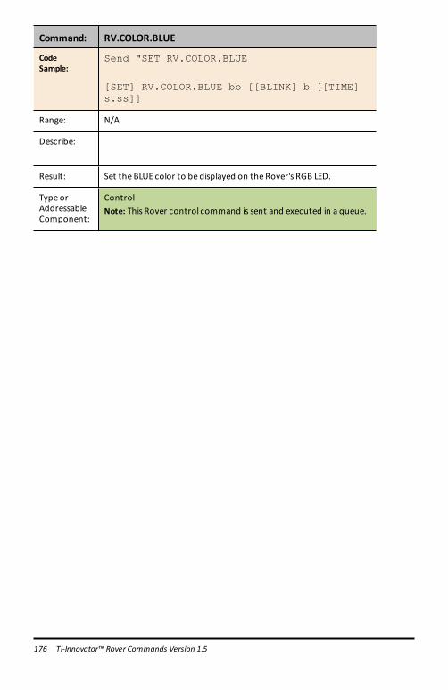
176 TI-Innovator™ Rover Commands Version 1.5
Command: RV.COLOR.BLUE
CodeSample:
Send "SET RV.COLOR.BLUE
[SET] RV.COLOR.BLUE bb [[BLINK] b [[TIME]s.ss]]
Range: N/A
Describe:
Result: Set the BLUE color to be displayed on the Rover's RGB LED.
Type orAddressableComponent:
ControlNote: This Rover control command is sent and executed in a queue.

RV Setup…
Send("SET Commands
• RV Setup…
– Send("SET– RV.POSITION– RV.GYRO– RV.GRID.ORIGIN– RV.GRID.M/UNIT– RV.PATH CLEAR– RV MARK
CE Calculators TI-Nspire™ CX
RV.POSITION
Command: RV.POSITION
CommandSyntax:
RV.POSITION
CodeSample:
Send "SET RV.POSITION"
[SET] RV.POSITION xxx yyy
[hhh [[DEGREES]|RADIANS|GRADIANS]]
Range: N/A
Describe: Sets the coordinate position and optionally the heading of theRover on the virtual grid.
Result: Rover configuration is updated.
Type orAddressableComponent:
Setting
RV.GYRO
Command: RV.GYRO
CommandSyntax:
RV.GYRO
CodeSample:
Send "SET RV.GYRO"
TI-Innovator™ Rover Commands Version 1.5 177

178 TI-Innovator™ Rover Commands Version 1.5
Command: RV.GYRO
Range: N/A
Describe: Sets the on-board Gyroscope.
Result:
Type orAddressableComponent:
Control (for Gyroscope)
RV.GRID.ORIGIN
Command: RV.GRID.ORIGIN
CommandSyntax:
RV.GRID.ORIGIN
CodeSample:
Send "SET RV.GRID.ORIGIN"
[SET} RV.GRID.ORIGIN
Range: N/A
Describe: Sets RV as being at current grid origin point of (0,0). The "heading" isset to 0.0 resulting in the current position of the RV now set topointing down a virtual x-axis toward positive x values.
Result:
Type orAddressableComponent:
Setting
RV.GRID.M/UNIT
Command: RV.GRID.M/UNIT
CommandSyntax:
RV.GRID.M/UNIT
CodeSample:
Send "SET RV.GRID.M/UNIT"
[SET] RV.GRID.M/UNIT nnn
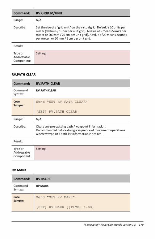
Command: RV.GRID.M/UNIT
Range: N/A
Describe: Set the size of a "grid unit" on the virtual grid. Default is 10 units permeter (100mm / 10 cm per unit grid). A value of 5means 5units permeter or 200mm / 20 cm per unit grid). A value of 20means 20unitsper meter, or 50mm / 5 cm per unit grid.
Result:
Type orAddressableComponent:
Setting
RV.PATH CLEAR
Command: RV.PATH CLEAR
CommandSyntax:
RV.PATHCLEAR
CodeSample:
Send "SET RV.PATH CLEAR"
[SET] RV.PATH CLEAR
Range: N/A
Describe: Clears any pre-existing path / waypoint information.Recommended before doing a sequence ofmovement operationswherewaypoint / path-list information is desired.
Result:
Type orAddressableComponent:
Setting
RV MARK
Command: RV MARK
CommandSyntax:
RVMARK
CodeSample:
Send "SET RV MARK"
[SET] RV MARK [[TIME] s.ss]
TI-Innovator™ Rover Commands Version 1.5 179

180 TI-Innovator™ Rover Commands Version 1.5
Command: RV MARK
Range: N/A
Describe: Enable RV to make a "mark"with a pen at the specified time interval(default is 1 second if not specified).A time value of 0.0 turns OFF marking.Marking ONLY happens if the Rover ismoving in a forward direction.
Result:
Type orAddressableComponent:
Setting (for Rover)

RV Control…
SEND(" CommandsWheel commands and other commands relevant for learning foundations of the Rovervehicle.
• RV Control …
– Send("– SET RV.MOTORS– SET RV.MOTOR.L– SET RV.MOTOR.R– SET RV.ENCODERSGYRO 0– READ RV.ENCODERSGYRO– READ RV.GYRO– READ RV.DONE– READ RV.ETA
CE Calculators TI-Nspire™ CX
SET RV.MOTORS
Command: SET RV.MOTORS
CommandSyntax:
SET RV.MOTORS
CodeSample:
Send "SET RV.MOTORS"
[SET] RV.MOTORS [LEFT][CW|CCW]<pwm value|BRAKE|COAST>
[RIGHT][CW|CCW]
<pwm value|BRAKE|COAST>
[DISTANCE ddd [M|[UNITS]|REV|FT]]
| [TIME s.ss]
Range: N/A
Describe: Set left or right or both motor PWMvalues. Negative values implyCCW and Positive values imply CW. Left CW=backward motion. LeftCCW=forward motion. Right CW=forward motion, RightCCW=backward motion. PWMvaluesmay be numeric from -255 to+255, or keywords "COAST" or "BRAKE". Value of 0 is stop (coast).Use of theDISTANCE option is only available if theRV is connectedwith all sensors. CONNECT RVMOTORSmeans no sensors areavailable to measure distance, so theDISTANCE option is an error in
TI-Innovator™ Rover Commands Version 1.5 181

182 TI-Innovator™ Rover Commands Version 1.5
Command: SET RV.MOTORS
this instance.
Result: Both the LEFT and RIGHTmotor, managed as a single object fordirect control (advanced) use.
Type orAddressableComponent:
ControlNote: This Rover control command is sent and executed in a queue.
SET RV.MOTOR.L
Command: SET RV.MOTOR.L
CommandSyntax:
SET RV.MOTOR.L
CodeSample:
Send "SET RV.MOTOR.L"[SET] RV.MOTOR.L [CW|CCW] <+/-pwmvalue|BRAKE|COAST>[TIME s.ss] | [DISTANCE ddd[[UNITS]|M|REV|FT]]
Range: N/A
Describe: Set left motor direct PWMvalue. CCW = forward, CW = backward,pwm value negative = forward, positive = backward. TIME optionavailable in allmodes, DISTANCE option available only when RV isfully connected (not theRVMOTORS option).
Result: Left wheelmotor and control for direct control (advanced) use.
Type orAddressableComponent:
ControlNote: This Rover control command is sent and executed in a queue.
SET RV.MOTOR.R
Command: SET RV.MOTOR.R
CommandSyntax:
SET RV.MOTOR.R
CodeSample:
Send "SET RV.MOTOR.R"
[SET] RV.MOTOR.R [CW|CCW] <+/-pwm

Command: SET RV.MOTOR.R
value|BRAKE|COAST>[TIME s.ss] | [DISTANCE ddd[[UNITS]|M|REV|FT]]
Range: N/A
Describe: Set right motor direct PWMvalue. CW = forward, CCW = backward,pwm value positive = forward, negative = backward. TIME optionavailable in allmodes, DISTANCE option available only when RV isfully connected (not theRVMOTORS option).
Result: Right wheelmotor and control for direct control (advanced) use.
Type orAddressableComponent:
ControlNote: This Rover control command is sent and executed in a queue.
SET RV.ENCODERSGYRO 0
Command: SET RV.ENCODERSGYRO 0
CommandSyntax:
SET RV.ENCODERSGYRO 0
CodeSample:
Send "SET RV.ENCODERSGYRO 0"
Range: N/A
Describe: Reset the left and right encoder, coupled with the gyro andoperating time information.
Result:
Type orAddressableComponent:
ControlNote: This Rover control command is sent and executed in a queue.
READ RV.ENCODERSGYRO
Command: READ RV.ENCODERSGYRO
CommandSyntax:
READRV.ENCODERSGYRO
TI-Innovator™ Rover Commands Version 1.5 183

184 TI-Innovator™ Rover Commands Version 1.5
Command: READ RV.ENCODERSGYRO
CodeSample:
Send "READ RV.ENCODERSGYRO"
Range: N/A
Describe: The left and right encoder, coupled with the gyro and operatingtime information.
Result: List of values of current left and right encoder, coupled with gyroand operating time information
Type orAddressableComponent:
ControlNote: This Rover READ command is executed immediately.
READ RV.GYRO
Command: READ RV.GYRO
CommandSyntax:
READRV.GYRO
CodeSample:
Send "READ RV.GYRO"
READ RV.GYRO [[DEGREES]|RADIANS|GRADIANS]
Range: N/A
Describe: The gyroscope is used to maintain the heading of Rover while it’s inmotion. It can also be used to measure the change in angle duringturns.
The gyroscope is ready to use after the CONNECT RV command isprocessed.TheGYRO object shall be usable even when the RV is not in motion.
Result: Returns current gyro sensor angular deviation from 0.0, readingpartially drift-offset compensated.
Type orAddressableComponent:
ControlNote: This Rover READ command is executed immediately.

READ RV.DONE
Command: READ RV.DONE
CommandSyntax:
READRV.DONE
CodeSample:
Send("READ RV.DONE")
Example: RV.DONE as an alias for RV.WAYPOINT.CMDNUM
CodeSample:
For n,1,16Send "RV FORWARD 0.1"Send "RV LEFT"EndFor
@ Wait for Rover to finish drivingSend "READ RV.DONE"Get dWhile d=0Send "READ RV.DONE"Get dWait 0.1EndWhileSend "READ RV.PATHLIST"Get L
Range: N/A
Describe: RV.DONE as an alias for RV.WAYPOINT.CMDNUMTo improve usability a new state variablewas created calledRV.DONE. This is an alias of RV.WAYPOINT.CMDNUM.
Result:
Type orAddressableComponent:
Returns Data
See Also: RV.WAYPOINT.CMDNUM
TI-Innovator™ Rover Commands Version 1.5 185
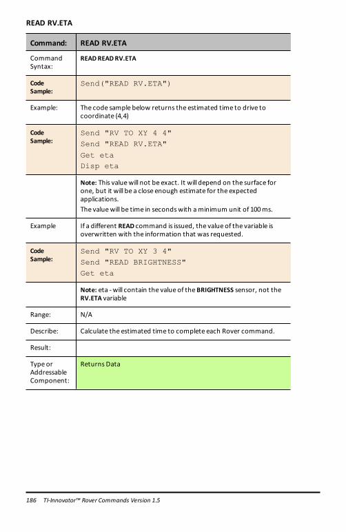
186 TI-Innovator™ Rover Commands Version 1.5
READ RV.ETA
Command: READ RV.ETA
CommandSyntax:
READREADRV.ETA
CodeSample:
Send("READ RV.ETA")
Example: The code sample below returns the estimated time to drive tocoordinate (4,4)
CodeSample:
Send "RV TO XY 4 4"Send "READ RV.ETA"
Get etaDisp eta
Note: This valuewill not be exact. It will depend on the surface forone, but it will be a close enough estimate for the expectedapplications.The valuewill be time in secondswith aminimum unit of 100ms.
Example If a different READ command is issued, the value of the variable isoverwritten with the information that was requested.
CodeSample:
Send "RV TO XY 3 4"Send "READ BRIGHTNESS"Get eta
Note: eta -will contain the value of theBRIGHTNESS sensor, not theRV.ETA variable
Range: N/A
Describe: Calculate the estimated time to complete each Rover command.
Result:
Type orAddressableComponent:
Returns Data

Sample program:
Set RGB to red while moving forward, green when turning.
CodeSample:
For n, 1, 4Send "RV FORWARD"Send "READ RV.ETA"
Get etaSend "SET COLOR 255 0 0"Wait etaSend "RV LEFT"Send "READ RV.ETA"Get etaSend "SET COLOR 0 255 0"Wait etaEndFor
TI-Innovator™ Rover Commands Version 1.5 187

188 TI-Innovator™ Rover Commands Version 1.5
Send "CONNECT RV"
SEND("CONNECT RV") CommandsCONNECT RV - initializes the hardware connections.
• Connects RV and inputs and outputs built into the RV.• Resets the Path and the Grid Origin.• Sets the units per meter to default value.• Send("CONNECT RV") CE Calculators TI-Nspire™ CX
CONNECT RV
Command: CONNECT RV
CommandSyntax:
CONNECT RV [MOTORS]
CodeSample:
Send "CONNECT RV"Send "CONNECT RV MOTORS"
Range: N/A
Describe: The "CONNECT RV" command configures the TI-Innovator™ Hubsoftware to work with the TI-Innovator™ Rover.It establishes the connections to the various devices on the Rover –two motors, two encoders, one gyroscope, one RGB LED and onecolor sensor. It also clears the various counters and sensor values.The optional ‘MOTORS’ parameter configures only themotors andallows direct control ofmotors without the additional peripherals.
Result: Connects the Rover Vehicle to the TI-Innovator™ Hub.This establishes connectionswith themotor driver, color sensor,gyroscope, ultrasonic ranger, and RGB LED.The Rover is now ready to be programmed
Type orAddressableComponent:
All components of the Rover - two motors, two encoders, onegyroscope, one RGB LED and one color sensor.

Send "DISCONNECT RV"
SEND("DISCONNECT RV") CommandsDISCONNECT RV - disconnects all the hardware peripherals from the Hub.
Format: Send("DISCONNECT RV")
• Send("DISCONNECT RV") CE Calculators TI-Nspire™ CX
DISCONNECT RV
Command: DISCONNECT RV
CommandSyntax:
DISCONNECT RV
CodeSample:
Send "DISCONNECT RV"
DISCONNECT RV
Range: N/A
Describe: The "DISCONNECT RV" command removes the logical connectionsbetween the TI-Innovator™ Hub and the TI-Innovator™ Rover.It also clears the counters and sensor values. It allows the use ofthe breadboard port of the TI-Innovator™ Hub with other devices.
Result: The TI-Innovator™ Hub is now logically disconnected from the TI-Innovator™ Rover
Type orAddressableComponent:
N/A
TI-RGB Array CommandsPrerequisite: Use the Send "Connect RGB" Command FirstThe "CONNECT RGB" command needs to be used first when using the TI-RGB Array.The "CONNECT RGB" command configures the TI-Innovator™ Hub software to workwith the TI-RGB Array.
TI-RGB Array Commands 189

190 TI-RGB Array Commands
It establishes the connections to the various led binary slots on the TI-RGB Array – 0through 15 RGB LED. It also clears the various counters and sensor values.
For additional commands see: education.ti.com/eguide
CONNECT RGB
Command: CONNECT RGB
CommandSyntax:
CONNECT RGB
CodeSample:
Send "CONNECT RGB"
Range: N/A
Describe: The "CONNECT RGB" command configures the TI-Innovator™ Hubsoftware to work with the TI-RGB Array.
Result: Connects the TI-RGB Array to the TI-Innovator™ Hub.The TI-RGB Array is now ready to be programmed
Type orAddressableComponent:
All components of the TI-RGB Array.See Also: Commands to usewith TI-RGB Array
Command: CONNECT RGB AS LAMP
CommandSyntax:
CONNECT RGB AS LAMP
CodeSample:
Send "CONNECT RGB AS LAMP"
Range: N/A
Describe: This command will enable the “high brightness”mode of the TI-RGBArray as long as an external power source (like theUSB battery) isconnected to the PWR port.Note: “AS LAMP”will need to be typed in.
Result: The TI-RGB Array is now configured to be in high-brightnessmode.If the external power is not connected, the “AS LAMP” has no effect– i.e. the brightness will be at the default level. Also note, an errorwill be indicated by a beep tone.
Type orAddressableComponent:
All components of the TI-RGB Array.See Also: Commands to usewith TI-RGB Array

SET RGB
Command: SET RGB n r g b
CommandSyntax:
SET RGB n r g bSET RGB eval(n) r g b
CodeSample:
Send "SET RGB 1 255 0 255"
Range: 0-15 for 'n', 0-255 for r,g,b
Describe: The SET RGB command controls the brightness and color of eachRGB LED in the TI-RGB Array
Result: The specific LED lights up with the specified color
Type orAddressableComponent:
All components of the TI-RGB ArraySee Also: Commands to usewith TI-RGB ArraySee Also: SET RGB ALL
SET RGB [n1 n2 n3…] r g b
Command: SET RGB [n1 n2 n3…] r g b
CommandSyntax:
SET RGB [n1 n2 n3…] r g b
Range: Amax of 16 LEDs can be specified.
CodeSample:
SET RGB [1 3 5 7] 200 0 200
Sets LEDs #1, 3, 5& 7 to purple (red + blue).Note: If using eval() with a variable for the LEDnumber, make surethere’s a preceding space before the ‘eval()’.SET RGB [ eval(i) eval(i+1) ] 255 0 255
Describe: Set the LEDs specified by their numbers to the specified color.
Result:
Type orAddressableComponent:
All components of the TI-RGB Array.
TI-RGB Array Commands 191

192 TI-RGB Array Commands
SET RGB PATTERN nnnn r g b
Command: SET RGB PATTERN nnnn r g b
CommandSyntax:
SET RGB PATTERN nnnn r g bnnnn – can be a decimal or a hexadecimal number.
Range: nnnn – 0 to 65535
CodeSample:
SET RGB PATTERN 100 255 0 255
Display the number 100 in binary form on the RGB array and set thecolor of the LEDs to purple.SET RGB PATTERN 0X100 255 0 0
Display the hexadecimal number 100 (equal to 256 in decimal) inbinary form on the RGB array and set the color of the LEDs to red.
Describe: Display the pattern indicated by the number using the specifiedcolor.
Result:
Type orAddressableComponent:
All components of the TI-RGB Array.
SET RGB ALL
Command: SET RGB ALL r g b
CommandSyntax:
SET RGB ALL r g b
CodeSample:
SET RGB ALL 255 0 255
SET RGB ALL 255 0 0
SET RGB ALL eval(R) eval(G) eval(B)
SET RGB ALL 0 0 0
Range:
Describe: To control all the LEDs in a single command use: SET RGB ALL r g b
Result: Control all LEDs in a single command
Type orAddressableComponent:
All components of the TI-RGB Array

READ RGB
Command: READ RGB
CommandSyntax:
Send "READRGB"
CodeSample:
Send "READ RGB"Get c
Range:
Describe: Returns the value of the current consumed by the TI-RGB Array inmA
Result:
Type orAddressableComponent:
All components of the TI-RGB ArraySee Also: New Commands to usewith TI-RGB Array
TI-RGB Array Commands 193