through-the-tube plugging with cpi / perma plugs
TRANSCRIPT

EST GROUP DC4015 05/96 REV 9 05/18
PAGE 1 OF 13
Questions? Contact EST Group Customer Service at any of the following locations.
www.cw-estgroup.com
North, Central & South America
EST Group Corporate Office 2701 Township Line Road Hatfield, PA 19440-1770 USA P: +1.215.721.1100
+1.800.355.7044 F: +1.215.721.1101 [email protected]
Europe / Middle East / Africa
EST Group B.V. Hoorn 312a 2404 HL Alphen aan den Rijn The Netherlands P: +31.172.418841 F: +31.172.418849 [email protected]
China P +86.400.636.5077 [email protected]
Singapore P +65.3158.5052 [email protected]
©2018 Curtiss-Wright
THROUGH-THE-TUBE PLUGGING WITH CPI / PERMA PLUGS
CPI / Perma Plugs are part of the Pop-A-Plug® Tube Plugging System. Unlike other tube plug designs, and under the proper conditions, CPI / Perma Plugs can be passed through the length of a straight heat exchanger tube and successfully installed at the far end of the tube without having direct access to both tube ends. This procedure outlines the information required to evaluating a heat exchanger for the through-the-tube plugging procedure, the limitations of the technique, and the installation process.
WARNING! SUCCESSFULLY INSTALLING CPI / PERMA PLUGS BY PASSING THEM THROUGH-THE-TUBE REQUIRES THAT THE OPERATOR CAREFULLY FOLLOW THIS PROCEDURE. THE OPERATOR SHOULD BECOME FAMILIAR WITH THIS PLUGGING PROCEDURE AND POSSESS A CLEAR UNDERSTANDING OF HOW TO INSTALL CPI / PERMA PLUGS AT THE NEAR END BEFORE ATTEMPTING THROUGH-THE-TUBE PLUGGING.
EVALUATING THE APPLICATION - INFORMATION REQUIRED:
1. Tube Size.What is the actual tube ID?
2. The tube-to-tubesheet connection.Is the tube-to-sheet connection expanded, welded, or both? If the tube is expanded the length of the expanded area is required to determine the position where the plug will be installed within the tube. CPI / PERMA PLUGS MUST NEVER BE INSTALLED IN THE TRANSITION ZONE BETWEEN EXPANDED AND UNEXPANDED AREA OF THE TUBE. If the tube is seal welded to the tubesheet then the weld material at the near tube end will need to be removed by lightly reaming with a tapered reamer.
BREAKAWAY(REMOVE PRIOR TO INSTALLATION)
ON NOSE END CPI/PERMA PLUGIT IS NORMAL TO SEE 3-4THDS EXPOSED
BREAKAWAY(REMOVE PRIOR TO INSTALLATION)
RING
PIN PIN
RING
PLUG SIZE & MATERIAL DESIGNATOR ARE STAMPED ON END OF PIN
"C" DENOTES CRS, "S" DENOTES SS, "B" DENOTES BRASS
(2) SERRATION PLUGWITH NOSE PIN
.471 - .512 ONLY
(3) SERRATION PLUGALL OTHER SIZES
EST GROUP DC4015 05/96 REV 9 05/18 PAGE 2 OF 13
Questions? Contact EST Group Customer Service at any of the following locations.
www.cw-estgroup.com
North, Central & South America
EST Group Corporate Office 2701 Township Line Road Hatfield, PA 19440-1770 USA P: +1.215.721.1100 +1.800.355.7044 F: +1.215.721.1101 [email protected]
Europe / Middle East / Africa
EST Group B.V. Hoorn 312a 2404 HL Alphen aan den Rijn The Netherlands P: +31.172.418841 F: +31.172.418849 [email protected]
China P +86.400.636.5077 [email protected]
Singapore P +65.3158.5052 [email protected]
©2018 Curtiss-Wright
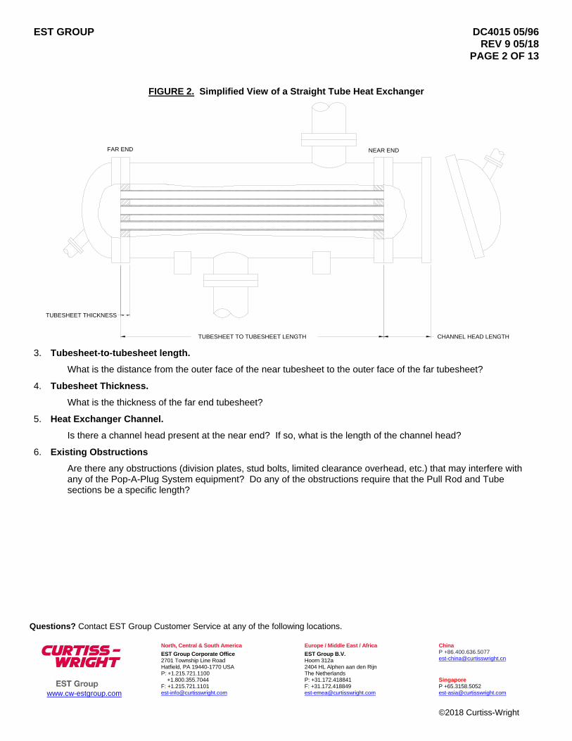
FIGURE 2. Simplified View of a Straight Tube Heat Exchanger
3. Tubesheet-to-tubesheet length.
What is the distance from the outer face of the near tubesheet to the outer face of the far tubesheet?
4. Tubesheet Thickness.
What is the thickness of the far end tubesheet?
5. Heat Exchanger Channel.
Is there a channel head present at the near end? If so, what is the length of the channel head?
6. Existing Obstructions
Are there any obstructions (division plates, stud bolts, limited clearance overhead, etc.) that may interfere with any of the Pop-A-Plug System equipment? Do any of the obstructions require that the Pull Rod and Tube sections be a specific length?
NEAR END
TUBESHEET TO TUBESHEET LENGTH
TUBESHEET THICKNESS
FAR END
CHANNEL HEAD LENGTH

EST GROUP DC4015 05/96 REV 9 05/18
PAGE 3 OF 13
Questions? Contact EST Group Customer Service at any of the following locations.
www.cw-estgroup.com
North, Central & South America
EST Group Corporate Office 2701 Township Line Road Hatfield, PA 19440-1770 USA P: +1.215.721.1100
+1.800.355.7044 F: +1.215.721.1101 [email protected]
Europe / Middle East / Africa
EST Group B.V. Hoorn 312a 2404 HL Alphen aan den Rijn The Netherlands P: +31.172.418841 F: +31.172.418849 [email protected]
China P +86.400.636.5077 [email protected]
Singapore P +65.3158.5052 [email protected]
©2018 Curtiss-Wright
LIMITATIONS OF THIS TECHNIQUE
While the through-the-tube plugging technique has proven to be both effective and reliable means for plugging tubes, several external factors can limit its success. These factors should be recognized and understood prior to starting.
1. Condition of the Tubes. The tubes to be plugged must be clean and free of any deposits. Deposits within the tubescan prevent the proper plug size from fitting through the tube to the far end of the heat exchanger. EST recommendshydroblasting and / or the use of aggressive tube cleaning brushes to clean the tubes. Some deposits may requirechemical cleaning. Hard deposits that cannot be removed by hydroblasting, brushing, or chemical cleaning mayrequire either drilling or rodding.
2. Damaged Tubes. Tubes that are extremely bowed, bent, or have failed as a result of tube denting, implosion orother tube ID altering factor may not allow the plug to be passed through the tube to the far end.
PRIOR TO PLUGGING
1. Clean the tube(s) thoroughly.
2. If the service of the heat exchanger permits, pierce the wall of the tube(s) in a location just beyond the tubesheet.The puncture should be cleanly through the tube wall.
DETERMINING THE PROPER CPI / PERMA PLUG SIZE
CPI / Perma Plugs and plug installation equipment will be selected based upon the tube ID. Actual tube measurements are best. Ideally the measurements should be taken at two locations, 90 degrees apart, at a point about 1” (25.4 mm) deep within the tube end. Further a number of tubes in both the inlet and outlet pass should be measured. If actual tube measurements are not available then the tube data (tube OD and wall thickness, or gage) may be obtained from the heat exchanger data sheet provided by the manufacturer. The tube data and the sizing guide shown in Appendix 1 may be used to determine the suggested CPI / Perma Plug size. Note: A careful evaluation of the repair history for the heat exchanger is also advised. If the tube bundle and/or tubes have been replaced, the actual tube size may vary considerably from the tube size indicated on the heat exchanger datasheet.
CALCULATE INSTALLATION DEPTH FOR FAR END PLUG
The CPI/Perma Plug must be installed into the tubesheet area of the tube only. EST recommends that the plug be positioned in the middle of the rolled area of the far end tube or the middle of the tubesheet if the tube is not rolled. To determine the proper Installation Depth subtract one half of the far end tube roll length from the tubesheet to tubesheet length. Refer to Figure 2.
Example: Tubesheet face to tubesheet face = 10 ft. = 120 in. Far end tube roll length or Tubesheet thickness if unrolled = 4” Installation depth = 120” - [1/2 x 4”] = 118” In this case the Installation Depth would be equal to 118”

EST GROUP DC4015 05/96 REV 9 05/18
PAGE 4 OF 13
Questions? Contact EST Group Customer Service at any of the following locations.
www.cw-estgroup.com
North, Central & South America
EST Group Corporate Office 2701 Township Line Road Hatfield, PA 19440-1770 USA P: +1.215.721.1100
+1.800.355.7044 F: +1.215.721.1101 [email protected]
Europe / Middle East / Africa
EST Group B.V. Hoorn 312a 2404 HL Alphen aan den Rijn The Netherlands P: +31.172.418841 F: +31.172.418849 [email protected]
China P +86.400.636.5077 [email protected]
Singapore P +65.3158.5052 [email protected]
©2018 Curtiss-Wright
REQUIRED INSTALLATION EQUIPMENT
CPI / Perma Plug installation hardware is dedicated to specific CPI / Perma Plug size(s) only. The following equipment is required:
1. A sufficient supply of CPI / Perma Plugs in the proper size and plug material.
2. Through-the-Tube Thread Adapter Kit(s) for the indicated plug size(s). Refer to the section titled Through-the-Tube Adapter Kit for more information on the Adapter Kits.
3. A Pop-A-Plug System Ram Package. Based on the plug size and material select either the Small Ram, Part Number PAP-6600, or Large Ram Package, Part Number PAP-1750. Note: V-1334 plug sizes and larger must be installed using the Medium Ram or Large Ram.
Small Ram PAP-6600
Medium Ram PAP-123
Large Ram PAP-1750
4. Air Regulator Assembly, Part Number REG-TTT.
5. A sufficient supply of Pull Rod and Tube Extensions to allow the CPI / Perma Plug to be positioned at the far end ofthe heat exchanger.
6. Additional Pop-A-Plug installation hardware is suggested as spares.
6.1. 1 additional Plug Positioner for each CPI / Perma Plug size.6.2. 1 additional Channel Head Pull Rod Assembly (4 ft. or 6 ft.)
7. (2) pair of Vise Grips.
8. 30’ tape measure.

EST GROUP DC4015 05/96 REV 9 05/18
PAGE 5 OF 13
www.cw-estgroup.com
North, Central & South America
EST Group Corporate Office 2701 Township Line Road Hatfield, PA 19440-1770 USA P: +1.215.721.1100
+1.800.355.7044 F: +1.215.721.1101 [email protected]
Europe / Middle East / Africa
EST Group B.V. Hoorn 312a 2404 HL Alphen aan den Rijn The Netherlands P: +31.172.418841 F: +31.172.418849 [email protected]
China P +86.400.636.5077 [email protected]
Singapore P +65.3158.5052 [email protected]
©2018 Curtiss-Wright
ASSEMBLY OF HYDRAULIC EQUIPMENT:
Installation of CPI / Perma Plugs at the far end of the heat exchanger requires that the Hydraulic Pump be operated to the installation pressure specified for the individual plug size and material, reference Table 1. The pulling pressures will also vary by the hydraulic ram used during installation. Installation pressures are shown in Table 2, Use of the Air Regular Assembly, Part Number REG-TTT, is mandatory.
1. Connect the Air Regulator assembly to the air input connection on the Hydraulic Pump, refer to Figure 3 below.
2. Connect the air supply to the Air Regulator input and set regulator to produce the proper hydraulic pressure byperforming the following steps.
a. Connect hydraulic hose and hydraulic ram only to hydraulic pump outlet.
b. Turn the Air Regulator adjustment knob fully counterclockwise.
c. Depress the Hydraulic Pump pedal while viewing the pressure gauge. While keeping pump pedal depressed,slowly adjust the Air Regulator knob clockwise to activate the pump. Continue operating the pump until theproper hydraulic pressure required for the CPI / Perma plug size and material is achieved.
FIGURE 3. Air Regulator Assembly and Hydraulic Pump
d. Depress the release end of the Hydraulic Pump pedal to release the built-up pressure. Repressurize the Pump toverify that the proper hydraulic pressure has been set. Adjust Air Regulator as necessary. Release pressure.
THROUGH-THE-TUBE ADAPTER KIT
The Through-the-Tube Adapter Kit includes a Through-the-Tube Adapter and a supply of Through-the-Tube Studs as shown in Figure 4. The Through-the-Tube (TTT) Adapter has a right hand male thread on one end and left-hand female thread on the other. The TTT Studs are threaded with both left and right hand threads. TTT Adapter Kits are plug size specific and are to be used in through-the-tube plugging applications in place of the breakaway supplied with the CPI / Perma Plugs. The applicable Adapter Kits for given plug sizes are shown in Tables 1 and 2. Adapter Kits should be installed as outlined in the following section.
Questions? Contact EST Group Customer Service at any of the following locations.
ADJUSTMENT KNOB
AIR REGULATOR ASSEMBLYPART NUMBER REG-TTT
AIR INPUT
ADJUSTMENT KNOB
HYDRAULIC PUMP
HYDRAULIC PUMP OUTPUT
PRESSURE GAUGE
EST GROUP DC4015 05/96 REV 9 05/18
PAGE 6 OF 13
Questions? Contact EST Group Customer Service at any of the following locations.
www.cw-estgroup.com
North, Central & South America
EST Group Corporate Office 2701 Township Line Road Hatfield, PA 19440-1770 USA P: +1.215.721.1100
+1.800.355.7044 F: +1.215.721.1101 [email protected]
Europe / Middle East / Africa
EST Group B.V. Hoorn 312a 2404 HL Alphen aan den Rijn The Netherlands P: +31.172.418841 F: +31.172.418849 [email protected]
China P +86.400.636.5077 [email protected]
Singapore P +65.3158.5052 [email protected]
©2018 Curtiss-Wright
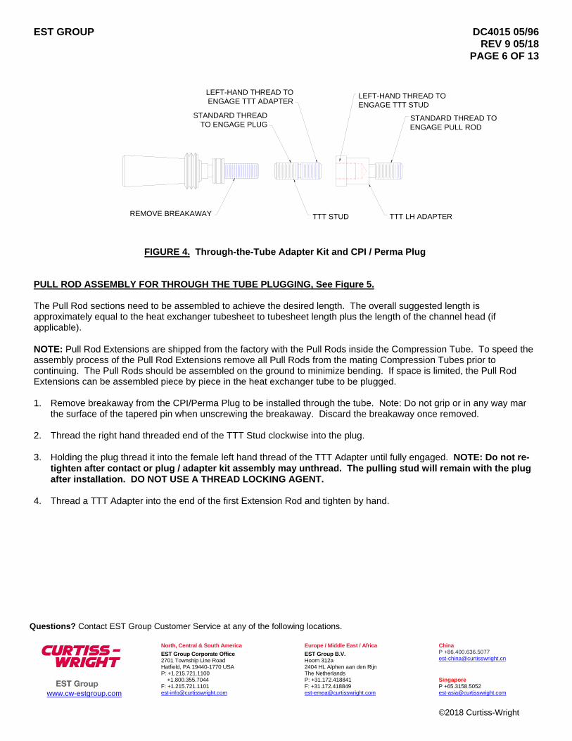
FIGURE 4. Through-the-Tube Adapter Kit and CPI / Perma Plug
PULL ROD ASSEMBLY FOR THROUGH THE TUBE PLUGGING, See Figure 5.
The Pull Rod sections need to be assembled to achieve the desired length. The overall suggested length is approximately equal to the heat exchanger tubesheet to tubesheet length plus the length of the channel head (if applicable).
NOTE: Pull Rod Extensions are shipped from the factory with the Pull Rods inside the Compression Tube. To speed the assembly process of the Pull Rod Extensions remove all Pull Rods from the mating Compression Tubes prior to continuing. The Pull Rods should be assembled on the ground to minimize bending. If space is limited, the Pull Rod Extensions can be assembled piece by piece in the heat exchanger tube to be plugged.
1. Remove breakaway from the CPI/Perma Plug to be installed through the tube. Note: Do not grip or in any way marthe surface of the tapered pin when unscrewing the breakaway. Discard the breakaway once removed.
2. Thread the right hand threaded end of the TTT Stud clockwise into the plug.
3. Holding the plug thread it into the female left hand thread of the TTT Adapter until fully engaged. NOTE: Do not re-tighten after contact or plug / adapter kit assembly may unthread. The pulling stud will remain with the plugafter installation. DO NOT USE A THREAD LOCKING AGENT.
4. Thread a TTT Adapter into the end of the first Extension Rod and tighten by hand.
LEFT-HAND THREAD TOENGAGE TTT STUD
LEFT-HAND THREAD TOENGAGE TTT ADAPTER
STANDARD THREADTO ENGAGE PLUG
REMOVE BREAKAWAY TTT STUD
STANDARD THREAD TOENGAGE PULL ROD
TTT LH ADAPTER

EST GROUP DC4015 05/96 REV 9 05/18 PAGE 7 OF 13
Questions? Contact EST Group Customer Service at any of the following locations.
www.cw-estgroup.com
North, Central & South America
EST Group Corporate Office 2701 Township Line Road Hatfield, PA 19440-1770 USA P: +1.215.721.1100 +1.800.355.7044 F: +1.215.721.1101 [email protected]
Europe / Middle East / Africa
EST Group B.V. Hoorn 312a 2404 HL Alphen aan den Rijn The Netherlands P: +31.172.418841 F: +31.172.418849 [email protected]
China P +86.400.636.5077 [email protected]
Singapore P +65.3158.5052 [email protected]
©2018 Curtiss-Wright
FIGURE 5. Pull Rod Assembly Set-up
WARNING! DURING THESE INSTALLATION PROCEDURES CARE MUST BE EXERCISED SO THAT THE EXTENSION RODS DO NOT ROTATE DURING TIGHTENING OR LOOSENING OF OTHER CONNECTIONS. FAILURE TO HEED THIS WARNING MAY RESULT IN THE THRU-THE-TUBE ADAPTOR PREMATURELY DISENGAGING FROM THE PLUG. 5. Install the Plug Positioner, with arrow pointing toward plug, onto the first Extension Rod. The Plug Positioner should
be installed so it rests against the plug. 6. Install the 6-inch long Tube, supplied as part of the Channel Head Assembly, onto the first Extension Rod so it is
against the back of the Plug Positioner. 7. Thread the next Extension Rod onto the previous Extension Rod and firmly hand tighten. Keep both Rods straight to
make certain that the joint is not subjected to bending while tightening. 8. Install the next Extension Tube over the Extension Rods. 9. Repeat steps 7 and 8 until the desired Extension length has been achieved. The desired length is approximately
equal to the heat exchanger tubesheet to tubesheet length plus the length of the channel (if applicable). 10. The Channel Head Rod should be threaded onto the Extension Rods and firmly hand tighten. Keep both Rods
straight to make certain that the joint is not subjected to bending while tightening. After tightening, verify that the joint cannot be loosened by hand. If it can, retighten. This is the last Rod section.
11. Install the remaining Tubes onto the Rod assembly. Remove slack from the Rod and Tube assembly by holding the
last Tube and pulling on the Channel Head Rod. 12. Set the Stand-Off Ring. A Stand-Off Ring is used to set the proper Installation Depth prior to installing the plug. The
Stand-Off Ring locks onto an Extension Tube by tightening a thumb screw, refer to Figure 6. Make a measurement from the middle of the ring back along the Extensions for a distance equal to the Installation Depth. Using a file, mark the Extension at that point. The mark is permanent and will allow you to check that the Stand-Off Ring is in the proper position prior to each plug installation. Slide the Stand-Off Ring to the mark and firmly tighten the thumbscrew.
NEXT EXTENSION ROD
FIRST COMPRESSION TUBE NEXT COMPRESSION TUBE
LOCK NUT
CPI/PERMA PLUG(NO BAW)
TTT STUD
FIRST EXTENSION ROD
TTT LH THREAD ADAPTER
KNURLED NUT
STAND-OFF RING
ROD & TUBE POSITIONER
PLUG POSITIONER
REMAINING TUBESCHANNEL HEAD ROD

EST GROUP DC4015 05/96 REV 9 05/18 PAGE 8 OF 13
Questions? Contact EST Group Customer Service at any of the following locations.
www.cw-estgroup.com
North, Central & South America
EST Group Corporate Office 2701 Township Line Road Hatfield, PA 19440-1770 USA P: +1.215.721.1100 +1.800.355.7044 F: +1.215.721.1101 [email protected]
Europe / Middle East / Africa
EST Group B.V. Hoorn 312a 2404 HL Alphen aan den Rijn The Netherlands P: +31.172.418841 F: +31.172.418849 [email protected]
China P +86.400.636.5077 [email protected]
Singapore P +65.3158.5052 [email protected]
©2018 Curtiss-Wright
FIGURE 6. Setting Stand-Off Ring
13. Install the Rod & Tube Positioner onto the Rod assembly with arrow pointing toward the plug. 14. Thread the Knurled Nut onto the exposed threads of the Channel Head Rod to hold the assembly together during the
next step. NOTE: Do not allow the rod to turn while threading on Knurled Nut as it could result in disengaging the TTT Adapter.
15. Plug should now be positioned for installation. When maneuvering the Pull Rod set-up make certain that it is
adequately supported to avoid bending. Slide the set-up, plug end first, into the heat exchanger tube to be plugged until the standoff ring is against the tube end. Remove slack from the Rod and Tube assembly by holding the last Tube and pulling on the Channel Head Rod.
16. Remove the Knurled Nut from the Channel Head Rod without turning rod. 17. Slide the hydraulic Ram onto exposed Channel Head Rod. The Ram should be installed so the Ram piston strokes
toward the operator. 18. Thread Knurled Nut onto the Channel Head Rod and firmly tighten against the Ram. Do not allow the rod to turn while
threading on Knurled Nut as it could result in disengaging the TTT Adapter. 19. Install the Ram Safety Cable then the locknut onto the Pull Rod and hand tighten. Verify that the Stand-Off Ring is
against the tube end. 20. While viewing the pressure gauge, press the Pump pedal to slowly pressurize the Ram. The Air Regulator, previously
adjusted, will allow only the set pressure to build. If it appears that the proper installation pressure is going to be exceeded, STOP and readjust Regulator as specified above. Continue to operate the Pump until the Ram bottoms out or the previously set installation pressure is reached.
NOTE: When the Ram piston bottoms out the hydraulic pressure will reach the set pressure only because the piston is at
the end of its travel. At this point it is still necessary to continue to step 19. 21. Release hydraulic pressure to allow the Ram to fully retract. Hold Ram handle while pulling on the Knurled Nut to
remove any slack from the set-up. Thread Knurled Nut so it is against the Ram and firmly tighten. Do not allow rod to turn when tightening the Knurled Nut.
INSTALLATION DEPTH
CPI/PERMA PLUG
STAND-OFF RING
RING

EST GROUP DC4015 05/96 REV 9 05/18 PAGE 9 OF 13
Questions? Contact EST Group Customer Service at any of the following locations.
www.cw-estgroup.com
North, Central & South America
EST Group Corporate Office 2701 Township Line Road Hatfield, PA 19440-1770 USA P: +1.215.721.1100 +1.800.355.7044 F: +1.215.721.1101 [email protected]
Europe / Middle East / Africa
EST Group B.V. Hoorn 312a 2404 HL Alphen aan den Rijn The Netherlands P: +31.172.418841 F: +31.172.418849 [email protected]
China P +86.400.636.5077 [email protected]
Singapore P +65.3158.5052 [email protected]
©2018 Curtiss-Wright
22. While viewing the pressure gauge, press the Pump pedal to slowly pressurize the Ram. Continue to operate the
Pump until the Ram bottoms out or the proper installation pressure is reached. If the Ram bottoms out, repeat step 19. If the proper installation pressure has been reached and the Knurled Nut cannot be hand tightened by more than 1/4 of a turn after the hydraulic pressure is released, the plug has been properly installed. If the proper installation pressure has been reached and the Knurled Nut can be hand tightened more than 1/4 of a turn after the hydraulic pressure is released, repeat steps 19 and 20 until the Knurled Nut cannot be hand tightened by more than 1/4 of a turn after the hydraulic pressure is released.
NOTE: Additional Adjustment of the Regulator may be necessary during this step. NOTE: Having to repeat steps 19 and 20, 4 to 5 times is not uncommon. 23. Released hydraulic pressure to allow the Ram to fully retract. 24. Remove the Knurled Nut and hydraulic Ram from the Rod. Do not allow the rod to turn while threading off the Knurled
Nut. 25. Reinstall the Knurled Nut to ensure that no parts slip off of the Rod. Apply a light pulling force while turning the Rod
clockwise to unthread the Pull Rod set-up from the installed plug. The Dual Thread Pulling Stud will remain with the installed plug. When disengaged withdraw the Pull Rod set-up from the tube. When maneuvering the Pull Rod set-up, make certain that it is adequately supported to avoid bending.

EST GROUP DC4015 05/96 REV 9 05/18
PAGE 10 OF 13
Questions? Contact EST Group Customer Service at any of the following locations.
www.cw-estgroup.com
North, Central & South America
EST Group Corporate Office 2701 Township Line Road Hatfield, PA 19440-1770 USA P: +1.215.721.1100
+1.800.355.7044 F: +1.215.721.1101 [email protected]
Europe / Middle East / Africa
EST Group B.V. Hoorn 312a 2404 HL Alphen aan den Rijn The Netherlands P: +31.172.418841 F: +31.172.418849 [email protected]
China P +86.400.636.5077 [email protected]
Singapore P +65.3158.5052 [email protected]
©2018 Curtiss-Wright
TABLE 1 ADAPTER KIT AND BAW IDENTIFICATION
TYPICAL CPI/PERMA PLUG (V-XXX-M)
CPI/PERMA
PLUG SIZE
Pin Thread
Number of Breakaway Identification Grooves
Through-the-Tube Adapter Kit
Brass* 304/316
Stainless Steel*
CRS and All Other Materials*
.471 10-32 2 N/A N/A TTT-1032
.471 12-28 N/A 1 1 TTT-1228
.491 12-28 1 1 1 TTT-1228
.512 12-28 1 1 1 TTT-1228
.524 12-28 1 0 0 TTT-1228
.555 12-28 1 0 0 TTT-1228
.584 1/4-28 0 1 2 TTT-1428
.621 1/4-28 0 2 2 TTT-1428
.649 1/4-28 0 2 2 TTT-1428
.670 1/4-28 0 2 2 TTT-1428
.712 1/4-28 1 2 2 TTT-1428
.735 1/4-28 1 2 2 TTT-1428
.774 5/16-24 3 1 1 TTT-51624
.804 5/16-24 3 1 1 TTT-51624
.837 5/16-24 3 1 1 TTT-51624
.853 5/16-24 3 1 1 TTT-51624
.899 5/16-24 3 1 1 TTT-51624
.919 5/16-24 0 1 1 TTT-51624
.962 5/16-24 0 1 1 TTT-51624
.979 5/16-24 0 1 1 TTT-51624
1.024 5/16-24 0 2 2 TTT-51624
1.054 5/16-24 0 2 2 TTT-51624
1.087 5/16-24 0 2 2 TTT-51624
1.103 5/16-24 0 2 2 TTT-51624
1.149 5/16-24 0 2 2 TTT-51624
1.171 5/16-24 0 2 2 TTT-51624
1.212 5/16-24 1 2 2 TTT-51624
1.334 1/2-20 1 2 2 TTT-1220
1.456 1/2-20 N/A 0 0 TTT-1220
1.578 1/2-20 N/A 0 0 TTT-1220
1.700 1/2-20 N/A 0 0 TTT-1220
1.822 1/2-20 N/A 0 0 TTT-1220
1.944 1/2-20 N/A 0 0 TTT-1220
*NOTE: BAW Identification are TYPICAL, always verify actual BAW on plug prior to setting installation pressure

EST GROUP DC4015 05/96 REV 9 05/18 PAGE 11 OF 13
Questions? Contact EST Group Customer Service at any of the following locations.
www.cw-estgroup.com
North, Central & South America
EST Group Corporate Office 2701 Township Line Road Hatfield, PA 19440-1770 USA P: +1.215.721.1100 +1.800.355.7044 F: +1.215.721.1101 [email protected]
Europe / Middle East / Africa
EST Group B.V. Hoorn 312a 2404 HL Alphen aan den Rijn The Netherlands P: +31.172.418841 F: +31.172.418849 [email protected]
China P +86.400.636.5077 [email protected]
Singapore P +65.3158.5052 [email protected]
©2018 Curtiss-Wright
TABLE 2 Hydraulic Installation Pressures For SMALL, MEDIUM, AND LARGE RAM PACKAGES.
THROUGH-THE-TUBE
ADAPTER KIT
PIN THREAD
BAW NUMBER OF GROOVES
INSTALLATION PRESSURE
SMALL RAM PSI BAR
MEDIUM RAM PSI BAR
LARGE RAM PSI BAR
TTT-1032 10-32 2 1,900 131 913 63 714 49
TTT-1228 12-28
0 3,000 207 1,441 99 1,127 78
1 2,100 145 1,009 70 789 54
2 2,700 186 1,297 89 1,014 70
TTT-1428 1/4-28
0 2,100 145 1,009 70 789 54
1 3,100 214 1,489 103 1,164 80
2 4,000 276 1,922 133 1,503 104
TTT-51624 5/16-24
0 4,000 276 1,922 133 1,503 104
1 5,300 366 2,546 176 1,991 137
2 6,600 455 3,171 219 2,479 171
3 3,100 214 1,489 103 1,164 80
TTT-1220 1/2-20
0 N/A 5,500 379 4,300 297
1 N/A 2,558 176 2,000 138
2 N/A 4,093 282 3,200 221
3 N/A 6,779 467 5,300 366
*NOTE: BAW Identification are TYPICAL, always verify actual BAW on plug prior to setting installation pressure

EST GROUP DC4015 05/96 REV 9 05/18
PAGE 12 OF 13
Questions? Contact EST Group Customer Service at any of the following locations.
www.cw-estgroup.com
North, Central & South America
EST Group Corporate Office 2701 Township Line Road Hatfield, PA 19440-1770 USA P: +1.215.721.1100
+1.800.355.7044 F: +1.215.721.1101 [email protected]
Europe / Middle East / Africa
EST Group B.V. Hoorn 312a 2404 HL Alphen aan den Rijn The Netherlands P: +31.172.418841 F: +31.172.418849 [email protected]
China P +86.400.636.5077 [email protected]
Singapore P +65.3158.5052 [email protected]
©2018 Curtiss-Wright
Table 3 Recommended CPI / Perma Plug Sizes For Use In Through-the-Tube Plugging Applications Only
WALL THICKNESS TUBE OD
BWG DECIMAL 5/8" 3/4" 7/8' 1" 1-1/4"10 .134 UNROLLED ID .482 .607 .732 .982
ROLLED ID .509 .634 .759 1.009 PLUG PART # N/A V-471 V-584 V-712 V-962
11 .120 UNROLLED ID .510 .635 .760 1.010 ROLLED ID .534 .659 .784 1.034
PLUG PART # N/A V-491 V-621 V-735 V-979
12 .109 UNROLLED ID .532 .657 .782 1.032ROLLED ID .554 .679 .804 1.054
PLUG PART # N/A V-512 V-621 V-735 V-979
13 .095 UNROLLED ID .560 .685 .810 1.060 ROLLED ID .579 .704 .829 1.079
PLUG PART # N/A V-524 V-649 V-774 V-1024
14 .083 UNROLLED ID .584 .709 .834 1.084ROLLED ID .601 .726 .851 1.101
PLUG PART # N/A V-555 V-670 V-804 V-1054
15 .072 UNROLLED ID .481 .606 .731 .856 1.106 ROLLED ID .495 .620 .745 .870 1.120
PLUG PART # V-471 V-584 V-712 V-837 V-1054
16 .065 UNROLLED ID .495 .620 .745 .870 1.120 ROLLED ID .508 .633 .758 .883 1.133
PLUG PART # V-471 V-584 V-712 V-837 V-1054
17 .058 UNROLLED ID .509 .634 .759 .884 1.134 ROLLED ID .521 .646 .771 .896 1.146
PLUG PART # V-491 V-621 V-735 V-853 V-1103
18 .049 UNROLLED ID .527 .652 .777 .902 1.152ROLLED ID .537 .662 .787 .912 1.162
PLUG PART # V-512 V-621 V-735 V-853 V-1103
19 .042 UNROLLED ID .541 .666 .791 .916 1.166 ROLLED ID .549 .674 .799 .924 1.174
PLUG PART # V-524 V-649 V-774 V-853 V-1149
20 .035 UNROLLED ID .555 .680 .805 .930 1.180ROLLED ID .562 .687 .812 .937 1.187
PLUG PART # V-524 V-649 V-774 V-853 V-1149
21 .032 UNROLLED ID .561 .686 .811 .936 1.186 ROLLED ID .567 .692 .817 .942 1.192
PLUG PART # V-524 V-670 V-774 V-919 V-1149
22 .028 UNROLLED ID .569 .694 .819 .944 1.194ROLLED ID .575 .700 .825 .950 1.200
PLUG PART # V-524 V-670 V-774 V-919 V-1171
23 .025 UNROLLED ID .575 .700 .825 .950 1.200ROLLED ID .580 .705 .830 .955 1.205
PLUG PART # V-555 V-670 V-804 V-919 V-1171
24 .022 UNROLLED ID .581 .706 .831 .956 1.206 ROLLED ID .585 .710 .835 .960 1.210
PLUG PART # V-555 V-670 V-804 V-919 V-1171
NOTE: Plug Part Numbers above do not include material designation. For recommended sizes in near end applications refer to CPI / Perma Plug rolled tube sizing chart shown in (DC1221).

EST GROUP DC4015 05/96 REV 9 05/18
PAGE 13 OF 13
Questions? Contact EST Group Customer Service at any of the following locations.
www.cw-estgroup.com
North, Central & South America
EST Group Corporate Office 2701 Township Line Road Hatfield, PA 19440-1770 USA P: +1.215.721.1100
+1.800.355.7044 F: +1.215.721.1101 [email protected]
Europe / Middle East / Africa
EST Group B.V. Hoorn 312a 2404 HL Alphen aan den Rijn The Netherlands P: +31.172.418841 F: +31.172.418849 [email protected]
China P +86.400.636.5077 [email protected]
Singapore P +65.3158.5052 [email protected]
©2018 Curtiss-Wright
THROUGH-THE-TUBE PLUGGING TECH TIP
When performing Through-the-tube (TTT) Plugging, the installation load from the hydraulic ram causes the pull rod to stretch and the compression tube to compress. The combined stretch and compression of the extensions takes away from effective travel of the pin relative to the ring. To explain differently, the small ram (PAP-6600) has a total stroke of 1” (25.4mm). If using the PAP-0200 as indicated below, the combined stretch and compression of a 20 foot (6.1m) extension assembly will be approximately 0.85” (21.6mm), refer to Table 1. This translates to approximately 0.15” (3.8mm) of pin travel relative to the ring (1” of ram stroke minus 0.85” of stretch/compression = 0.15” pin movement (25.4mm or ram stroke minus 21.6mm of stretch/compression equals 3.8mm of pin travel relative to the ring)). So when a full stroke of the ram is seen during installation the plug at the far end of the exchanger has only stroked by approximately 0.15” (3.8mm). This is why the TTT Plugging instructions indicate that the ram must be repeatedly stroked to the installation pressure and when released, the knurled nut cannot be tightened by more than ¼ of a turn. This repeated stroking insures that the plug will be properly installed.
Question: What is the longest length of TTT extension we can use?
Answer: The rule of thumb is roughly 20feet (6.1m) for the small ram (PAP-6600) and 40feet (12.2m) for the large ram (PAP-1750). Tubes longer than 40 feet (12.2m) can be plugged using the TTT technique provided a hydraulic ram with enough stroke to overcome the stretch/compression is utilized. Please contact EST Group for information regarding your specific application.
Table 4, below, shows the combined stretch/compression of our 20foot (6.1m) Rod and Tube Extension Assemblies.
Note: The stretch/compression will be less for shorter extension assemblies and more for longer extension assemblies.
Table 4 Rod and Tube Extension Assembly Stretch / Compression During TTT Plugging
Part NumberStretch/Compression of
20ft. Assembly (in)Breakaway Pressure
(psi)Pull Rod OD
(in)Compression Tube
OD (in)Breakaway
ThreadPAP-0200 0.85 2700 5/16 7/16 12-28PAP-0201 0.71 3000 5/16 1/2 12-28PAP-0202 0.72 4000 3/8 9/16 1/4-28PAP-0213 0.80 6600 1/2 11/16 5/16-24PAP-0203 0.68 6600 1/2 3/4 5/16-24PAP-0204 0.40 3200 (Lg. Ram) 3/4 1 1/8 1/2-20PAP-0205 0.32 3200 (Lg. Ram) 7/8 1 1/4 1/2-20