through stop logs excellence - liquetec...
TRANSCRIPT
SLIDEGATESSLIDEGATES
WEIR GATESWEIR GATES
STOP LOGSSTOP LOGS
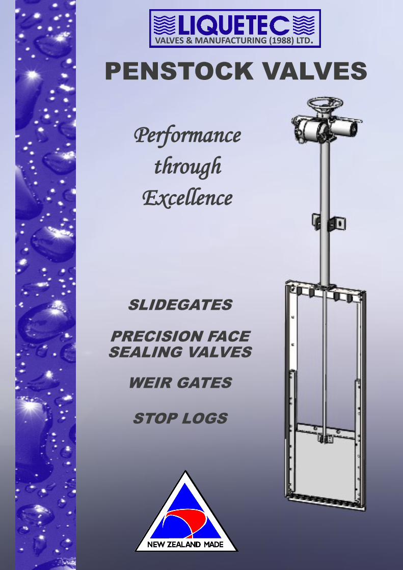
PENSTOCK VALVESPENSTOCK VALVESPENSTOCK VALVES
SLIDEGATES
PRECISION FACE
SEALING VALVES
WEIR GATES
STOP LOGS
Performance
through
Excellence
VALVES & MANUFACTURING (1988) LTD.

SLIDEGATES
Slide gate valves are designed for bulk fluid containment where on or off seat pressures oc-
curs and drop tight closure is not essential.
Liquetec Slidegates Feature:
Water, sewage, effluent or pollution control.
Purpose Designed to comply with
project requirements
Stainless Steel or Hot Dipped
Galvanised Mild Steel
Sized to fit an orifice from 150mm to
2500mm, round square or rectangular.
Rising or Non-Rising Spindle
Actuation
Mounting
Fastening
Installation
Contact Us Get a Quote
Component Material
1 Mounting Wall Reinforced Concrete
2 Penstock Gate 316 or 304 Stainless Steel
or other as specified
3 Gate Guide/Seal U.H.M.W. Polyethylene
4 Gate Guide/Seal
Cover Bar
316 or 304 Stainless Steel
or other as specified
5 Frame anchor
studs
316 Stainless Steel
6 Slidegate Frame 316 or 304 Stainless Steel
or other as specified
7 Installation
Masonry
Grout
2
3
4 5
6
7
1
More info..

1. Concept Slide gate valves are designed for bulk fluid containment where on or off seat pressures occurs and drop tight closure is not essential. Gate reinforcing, when required, is carried out in the horizontal direction only to allow the gate to conform to any vertical frame distortion created by headwall irregularities. These valves are supplied as a one piece integral unit for direct placement over pre installed wall anchors. Size range 150mm to 2500mm round, square or rectangular. 2. General Gates, lifts, stems and accessories are of a design and material specification suitable for the ap-plication intended and are constructed of steel except for items specified separately. 3. Gate Seat and Angle Frame The gate frame is of the flat back type. The gate, seat and angle frame is an integral part of structural shapes, assembled by welding to form the waterway opening. Slide angles, spacer bars and cover bars form guides for the slide, with holes provided for mounting the anchor bolts. The gate frame cross section is designed to provide a slot width, giving a minor clearance over gate thickness. The angle frame is self contained and furnished with an angle section head frame. The head frame is attached to the guide angles by two bolts per slide. All parts of the frame will with-stand the thrust developed during gate operation under full head. 4. Gate slide The gate slide is fabricated from steel plate, reinforced with horizontal stays of angle or chan-nel section where required to limit deflection under full head to less than 1/360 of the span. The slide is provided with a pocket attached by welding, to receive the stem. The pocket is ca-pable of taking the full thrust developed during gate operation. The gate slide will make uniform contact with the surface of the seal when it is closed, without causing damage to the seal material. 5. Flush bottom seal The valves all carry a flush bottom seal which is securely fastened to the bottom cross member of the frame by bolts and a retaining plate. The seal is of Flat Section black Neoprene and is removable without disturbing the concrete in the invert of the opening. 6. The frame seal face/bearing and gate spacer bars consist of U.H.M.W. POLYETHYLENE gauged flat bars drilled to allow fixing to the frame by the specified wall studs and nuts. These seat seal bars form a resilient seat with a very low coefficient of friction which greatly enhances operation of the valve. 7. Stem/Spindle The valve stem is of grade 303/316 stainless steel and will withstand twice the force created by a 20 kg pull on the hand wheel providing that the stem travel nut is correctly positioned to pre-vent an over travel tendency of the gate slide when closed. The threaded portion of the stem has an acme form – machine cut thread of left hand pitch to give clockwise closure. The bottom end of the stem is drilled to accept stainless steel clevis bolts. The stem is supported by a nylon guide bush at the head frame elevation, and is flanged to ac-
Liquetec Slidegates - General Specifications
8. Stem/Spindle Nut The stem nut is of Gunmetal Bronze threaded to class 2A clearance – left hand Acme form. Stems should be specified as Rising or Non Rise type. Preference is for rising type where stem and nut are free from contamination from the medium being controlled and are readily available for maintenance inspection and servicing. 9. Lifts/Actuation 1.1 Hand wheel Operator Manual hand wheel via bevel gear drive to required ratio. Double Acting Pneumatic Cylinder. Double Acting Hydraulic Cylinder. Electric. Stem Cover may be specified. Gate position indication may be specified. 10. Actuator or Pedestal Upstand – When required The upstand is fabricated from mild steel stainless steel sections and flanged to suit appli-cation intended. Mild steel work is Hot Dip Galvanised or Epoxy coated as required. 11. Design life of Gates The gates will be able to weather a 30 year plant life assuming minimum usage and mini-mum maintenance all things being equal... 12. Slide Gate Installation Suitable for installation by other supported by the manufacturers. 13. Stem Support Guide Bracket Wall mounted and adjustable, the spindle support bracket is fabricated from stainless steel sections flanged for mounting to the headwall where required. The bracket is ad-justable to allow ease of positioning to suit stem alignment. The guide bearing is of nylon. All steel work and fasteners are Hot Dip Galvanised. Stem support is recommended every 2 metre spam of stem. 14. Installation Kits Consisting of :- Fully marked up and predrilled timber template complete with drilling guide bush. A full set of masonry anchors as specified. A full set of wall studs complete with nuts and washers as specified. 15. Material Options :- Totally in 316 Stainless Steel Totally in 304 Stainless Steel Totally in Aluminium Carbon Steel Galvanised 16. Design Options Weir slide gates. Open channel slide gates. Special Purpose Slide gates.
Liquetec Slidegates - General Specifications Continued.

PRECISION FACE SEALING
PENSTOCK VALVES
Actuation
Mounting
Fastening
Installation
1
2
3
4
5
6
7
Sealing face between U.H.M.W. Polyeth-ylene and Penstock Frame
Stainless Steel Gate Buffer. For Mild Steel Valves only.
8
9
Contact Us Get a Quote
Component Material
1 Wedge system 316 Stainless Steel
2 Penstock Gate 316 or 304 Stainless Steel,
Epoxy Coated Mild Steel.
3 Gate Seal U.H.M.W. Polyethylene
4 Penstock Frame 316 or 304 Stainless Steel,
Epoxy Coated Mild Steel.
5 Installation
Masonry
Grout
6 Gate Guide
Ribs
316 or 304 Stainless Steel,
Epoxy Coated Mild Steel.
7 Frame anchor
studs
316 S.S.
8 Mounting Wall Reinforced Concrete
9 Gate Runner 316 or 304 Stainless Steel,
Epoxy Coated Mild Steel.
Liquetec PFSP Valves Feature:
Purpose Designed
Used for water, sewage, effluent or
pollution control.
Stainless Steel or Epoxy Coated Mild Steel.
Sized to fit an orifice from 150mm to
2500mm, round square or rectangular.
Rising or Non-Rising Spindle
Gate closing wedge system
More info..

Liquetec Precision Face Sealing Penstock Valves - General Specifications
Valve
The unit is designed to be flush mounted onto a headwall or flange mounted to piping in size ranges from 150mm to 2500mm, with square, rectangular or circular opening.
The purpose of the valve is to control the flow of liquid to the pressures set out in drawings relevant to the proposed project.
Construction Frame - Carbon steel frame, 316 or 304 Stainless Steel.
Gate - Carbon steel frame, 316 or 304 Stainless Steel.
Seat - 316 Stainless Steel raised, fully welded and machined
Slide Strips - 316 Stainless Steel , fully seal welded.
Gate runners- 316 or 304 Stainless Steel, bolted to the frame
Gate Wedges - 316 or 304 Stainless Steel blocks, adjustable.
Spindle - 303 Stainless Steel threaded acme, left hand for right hand closure.
Spindle Nut - Bronze class 2A fit. Acme thread.
Fasteners - 316 Stainless Steel
Gate Buffer - 316 Stainless Steel
Gate Stop - 316 Stainless Steel
Gate Seal - Resilient polyethylene material, raised face—fixed with Replaceable Stainless Steel fasteners.
Actuation
Rising or non-rising spindle. Direct 1:1 handwheel operation Manual handwheel via worm gear/bevel gearbox. Pneumatic on/off or positioning cylinder. Hydraulic Electric Penstock Mounting Kits Fully marked up and pre-drilled timber templates for accurate positioning of masonry anchors. Full set of mounting studs complete with hex nuts and washers, all in 316 Stainless Steel. Corrosion Prevention All welds are fully sealed Carbon steel surfaces are sand blasted to Swedish standard SA2.5, then treated with reinforced inorganic zinc or continuous immersion, as required. A special epoxy coatings is applied to withstand abrasions and moisture penetration. Colour Top coat colours of metallic grey, green or white, may be specified. Inquires Every situation for penstock Valves will vary, thus: Pressure rating, seal requirements and actuation must be matched to suit the application. Marked up general assembly drawings only can be provided against any inquiry. Fully detailed drawings are produced to suit each penstock requirement at the time of the placement of order. Required by Liquetec is: Application Head direction (on seat/off seat) Orifice shape and size Spindle (rising or non-rising) Actuation method required Sealing From specified permissible leakage rates to near drip tight. Gate sealing is achieved by a positive Liquetec wedge system with final adjustments being made during installation. Installation The fixing of the masonry anchors and any grouting is normally carried out by the civil contractors, while the installation and testing is of a mechanical nature and can be carried out by the manufacturer.
WEIR GATESWEIR GATESWEIR GATES
Actuation
Mounting
Fastening
Installation
Contact Us Get a Quote
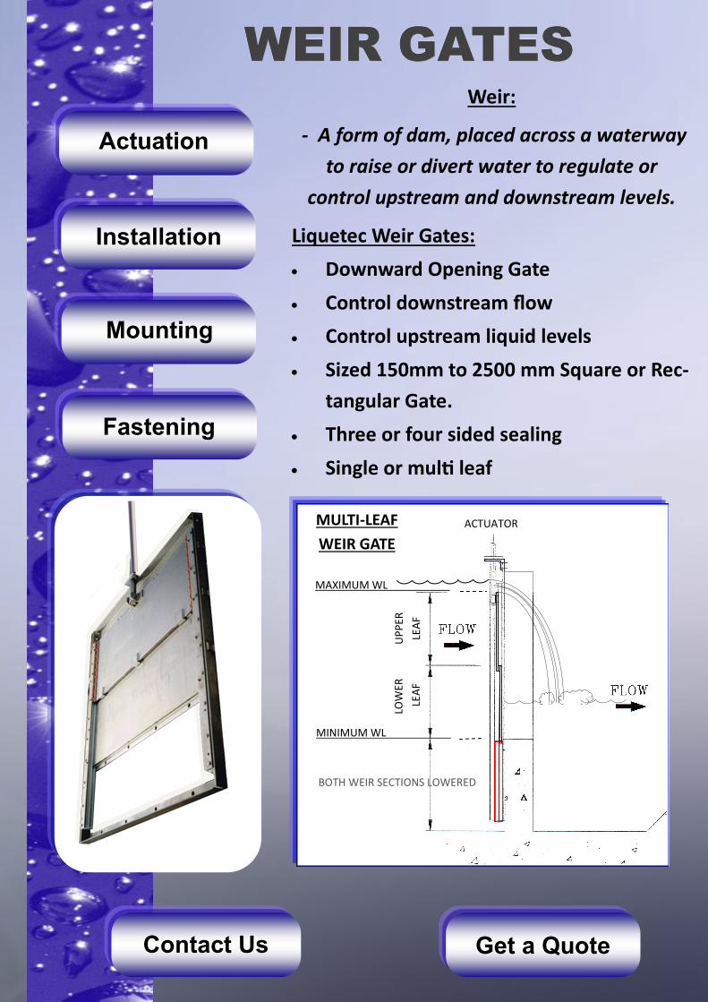
Weir:
- A form of dam, placed across a waterway
to raise or divert water to regulate or
control upstream and downstream levels.
Liquetec Weir Gates:
Downward Opening Gate
Control downstream flow
Control upstream liquid levels
Sized 150mm to 2500 mm Square or Rec-
tangular Gate.
Three or four sided sealing
Single or multi leaf
BOTH WEIR SECTIONS LOWERED
LOW
ER
LEA
F
UP
PER
LEA
F
MINIMUM WL
ACTUATOR
MAXIMUM WL
MULTI-LEAF
WEIR GATE
STOP LOGSSTOP LOGSSTOP LOGS
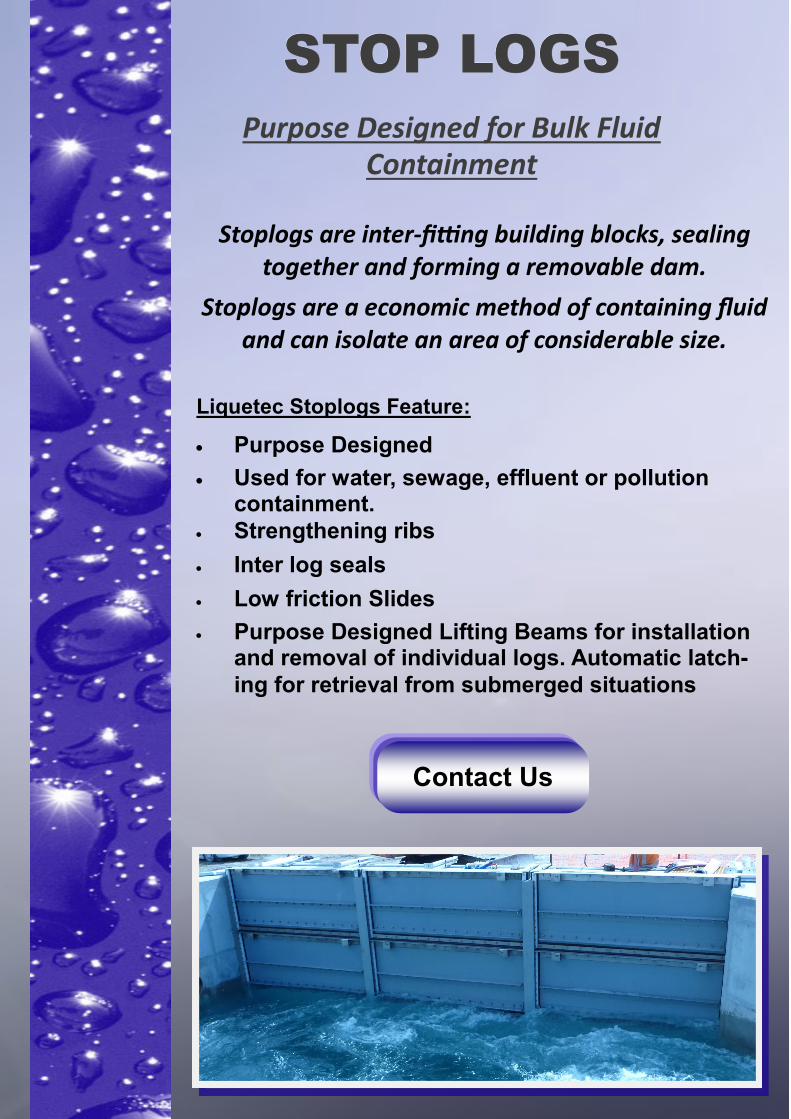
Purpose Designed for Bulk Fluid Containment
Stoplogs are inter-fitting building blocks, sealing together and forming a removable dam.
Stoplogs are a economic method of containing fluid and can isolate an area of considerable size.
Liquetec Stoplogs Feature:
Purpose Designed
Used for water, sewage, effluent or pollution containment.
Strengthening ribs
Inter log seals
Low friction Slides
Purpose Designed Lifting Beams for installation and removal of individual logs. Automatic latch-
ing for retrieval from submerged situations
Contact Us

ACTUATIONACTUATIONACTUATION
Key Actuation:
Using a Square Drive or a Cap Dolly Drive, the
spindle is turned with a corresponding
removable tool.
Rising or Non-Rising Spindle.
Handwheel Actuation:
Standard Liquetec Handwheels are cast iron,
complete with Gunmetal Bronze spindle nut
when rising spindle is required
Rising or Non-Rising Spindle
Bevel Gear Drive Actuation:
Available in 2:1, 3:1 and 4:1 reduction ratio. Vertically mounted hand wheel. Rising and Non-Rising Spindle.
Electrical Actuation:
High torque capabilities Torque overload switches Limit the number of turns of the spindle Replaceable bronze drive nut Manual override Positional controlled Rising and Non-Rising Spindle
Pneumatic or Hydraulic Actuation
Uses air or fluid to lift or lower the penstock or
slidegate.

MOUNTINGMOUNTINGMOUNTING
HILTI CHEMICAL ANCHORS
The following illustrates the different configura-
tions in which a penstock valve can be mounted
to a wall, pipe or channel.
CHANNEL MOUNTED AND RECESS CHANNEL MOUNTED
FLUSH FLOOR MOUNTED AND REINFORCED FLUSH FLOOR MOUNTED
WALL MOUNTED

FASTENINGFASTENINGFASTENING
Concrete Inserts for casting into new
head-works and incorporating reinforc-
ing steel rod. Available in common sizes
Hilti HVU adhesive anchors for concrete.
Available in common sizes. Mechanical
fracture of the capsule allows the resin to
harden for high strength retaining of wall
studs
Hilti HAD Mechanical Anchor. Available in
all common sizes.
Another solution for heavy duty fastening
INSTALLATIONINSTALLATIONINSTALLATION
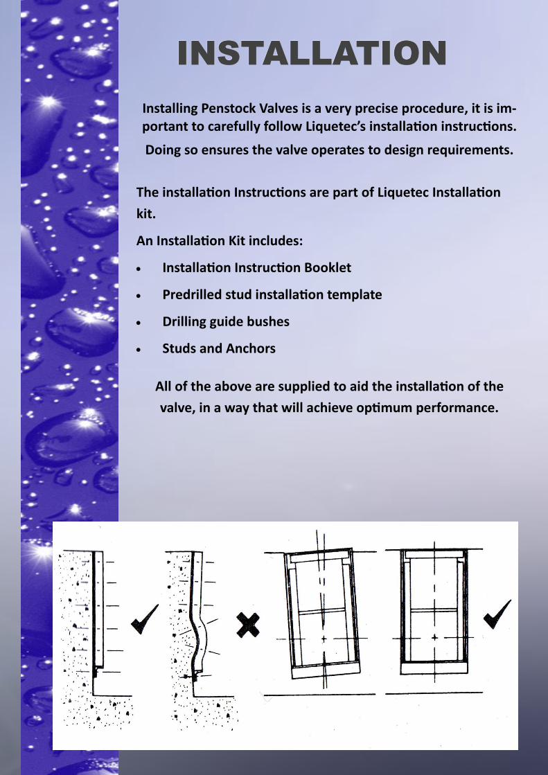
Installing Penstock Valves is a very precise procedure, it is im-portant to carefully follow Liquetec’s installation instructions.
Doing so ensures the valve operates to design requirements.
The installation Instructions are part of Liquetec Installation
kit.
An Installation Kit includes:
Installation Instruction Booklet
Predrilled stud installation template
Drilling guide bushes
Studs and Anchors
All of the above are supplied to aid the installation of the
valve, in a way that will achieve optimum performance.

GET A QUOTEGET A QUOTEGET A QUOTE