three-leaf masonry walls in archaeological islamic
TRANSCRIPT

)١٣( مجلة الاتحاد العام للآثاريين العرب ـــــــــــــــــــــ
- 124 -
Three-Leaf Masonry Walls in Archaeological Islamic Buildings in Cairo and the Use of Embedded Timber
Ties in Its Restoration and Retrofit
♦♦♦♦ Dr. Yaser Yehya Amin Abdel-Aty
Keywords: Three-leaf masonry walls, Timber-ties, Structural Behavior, Restoration.
Abstract This research studied the construction technology of various
typologies of three-leaf masonry walls in archaeological Islamic buildings in Cairo. It highlighted on the core layer of these walls, and its main structural role, especially in moderate and wide thickness' walls. It studied analytically, using numerical modeling technique that utilizing Finite Element Method; the share of each layer in the three-leaf masonry walls under vertical loads and reached to correlate it with normal stiffness during elastic phase. This paper also studied the development and structural functions of embedded timber ties in masonry walls; in both Egypt and world-wide. It demonstrated the structural behavior and failure mechanisms of the three-leaf masonry walls under vertical loads, using results of both structural analysis work of numerical models (conducted in this paper) and pervious experimental work of latest researches in this field. It studied the use of timber ties in restoration and reinforcing of deficient historic three-leaf masonry walls. Finally, conclusion and recommendations were derived.
1. Introduction Historic masonry walls that follow multiple-leaf construction
systems are not sufficiently studied; although the wide interest and researches that were achieved in the last two decades, which concerning various aspects of historic masonry works. Most of those researches had covered brick-masonry, especially the
♦♦♦♦ Lecturer at Cairo University, Faculty of Archaeology, Restoration Department

)١٣( مجلة الاتحاد العام للآثاريين العرب ـــــــــــــــــــــ
- 125 -
contemporary infill frames in modern constructions, and single-leaf masonry walls. Whilst; few researches had studied experimentally and analytically models of multiple-leaf historic masonry walls, with relative dimensions, building materials and construction technology that represent certain case-studies; they did not cover the wide variety of other types of these walls; especially those in our Islamic architectural heritage. The lack of researches that concern three-leaf masonry walls is due to their wide variety of building materials and construction technologies all over the World, and insufficiency of information and data that could be obtained from ruined and deficient historic buildings; since these data are difficult to be attained from undamaged structures. These reasons impose difficulties on researches and on possibility to reach results that cover wide range of walls, similar to single-leaf brick-masonry walls. The importance of studying this type of masonry walls refers to the fact that most of historic structures, both worldwide and in Egypt; depends on load-bearing masonry walls, as being its main vertical supporting elements. The majority of these load-bearing walls were built following three-leaf construction system (i.e. two external leaves of ashlars' stone masonry with a core layer in-between); especially for basement and ground floors.
Similar to contemporary engineering materials (e.g. reinforced concrete, etc.); masonry works require wide and intensive research programs, both experimental and analytical; to reach better understanding of its various structural behaviors. Evaluation of structural safety for historic three-leaf masonry walls depends on good understanding of its structural behavior and failure mechanisms, which would help to achieve successful and economic restoration and retrofitting works for them. Most previous researches assumed core layer in these walls as only an infill that was built of 'almost' mortar with few amount of small rubble stones or broken bricks, similar to contemporary plain concrete. Thus, they presumed that most (or even all) imposed vertical loads on wall are carried on the two external leaves only. This hypothesis can be right

)١٣( مجلة الاتحاد العام للآثاريين العرب ـــــــــــــــــــــ
- 126 -
in case of two-leaf walls and three-leaf with slim core. But it was generally not applicable to most of three-leaf masonry walls in Islamic architectural heritage in Cairo; since most of them contain moderate to wide thickness core layers, which were built following random rubble stone masonry work. This would affect the structural behavior and failure mechanisms of these historic walls and consequently its restoration mythology.
The present research had carried out a wide survey on three-leaf masonry walls in archaeological Islamic buildings in Cairo. It focused on ruined and fallen down structures; to study construction technology and building materials of these masonry walls. The survey results helped with other studies, including numerical analysis that utilized Finite Element Method (F.E.M.); to better understand the structural role of core layer and to analyze the various functions of embedded timber ties and its use in the restoration of deficient and damaged walls. Thus, the present research studied the followings: • Various construction technology and typology of three-leaf
masonry walls in archaeological Islamic buildings in Cairo, and established another theory for its construction, that concern moderate and wide thickness three-leaf masonry walls.
• The development of using timber ties and timber frames in historic masonry constructions.
• Structural behavior and failure mechanisms of three-leaf masonry walls, through results of both analytical numerical investigation by the researcher and the latest experimental researches abroad.
• The use of timber-ties in restoration and retrofitting of historic masonry walls, with some examples from achieved projects.

)١٣( مجلة الاتحاد العام للآثاريين العرب ـــــــــــــــــــــ
- 127 -
2. Hypotheses of construction technology for three-leaf masonry walls in archaeological structures in Cairo
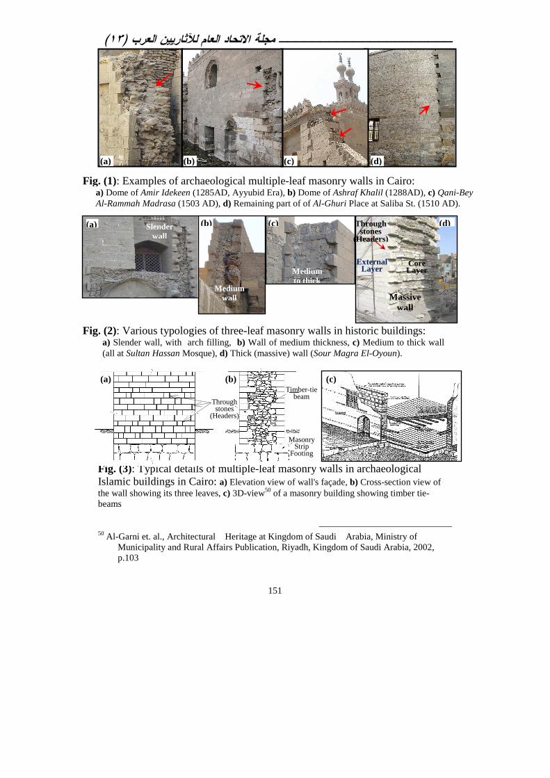
Three-leaf masonry walls in historic structures are the type of multiple-leaf masonry walls, which are built of two external leaves of coursed ashlars' stone masonry, and a core layer in-between of random rubble uncoursed stone masonry [1]; see Figures (1) to (3). The core layer was always thought to be heterogeneous and weak infill layer that was built of small broken stones (i.e. rough rubble stones) and/or broken red-bricks in abundance of mortar; similar to contemporary plain concrete. Hence, many hypotheses presumed that wall's bearing capacity and mechanical strength depend mainly on its two outer leaves [2], while core layer is merely an infill part; which increases wall's thickness, reduces its overall resulting internal stresses and increases its stability.
In general, masonry work that follows three-leaf construction system was always used with load-bearing walls, piers and some-times vaults at historic structures. It provided economic thick masonry work, which its structural stability depended on massive elements that combated and eliminated tensile stresses through safe compressive stresses, besides maintaining buckling criteria. The massive masonry also helped in thermal and sound insulation. Load-bearing masonry walls were always built of stone three-leaf system at basement and ground floors, besides the walls that extends for long heights (e.g. external façade walls and double-height walls of upper floor rooms). Walls at upper floors, especially inner rooms, were generally built of single-leaf red-brick masonry work that surfaces were coated with plaster and hanging ornaments.
Owing to the complexity of these types of historic masonry walls and the wide variety of its building materials and construction
[1] Binda, L. et al., A contribution for the understanding of load-transfer mechanisms in multi-leaf masonry walls: Testing and modeling, Journal of Engineering Structures, Issue No. 28, Elsevier ltd, www.elsevier.com/locate/engstruct, 2006, p. 1132. [2] Pina-Henriques, J., et al., Testing and modelling of multiple-leaf masonry walls under shear and compression. Proceedings of the 4th International Seminar on Structural Analysis of Historical Constructions, Balkema, 2004: p. 299–310.

)١٣( مجلة الاتحاد العام للآثاريين العرب ـــــــــــــــــــــ
- 128 -
technology; few numbers of previous researches had studied these types of masonry walls. Most of these researches did not study the construction technique of these walls; especially its core layers. They generally focused on studying, experimentally and analytic-ally; its structural behavior and failure mechanisms under various loading types. The present research highlights the significant structural roles of the core layer in historic three-leaf masonry walls, which constituted considerable part of its thickness.
First hypothesis [3] presumed that three-leaf masonry walls in historic buildings in European countries were constructed by building the outer two leaves first, up to 1.0 m high, and then components of core (infill) layer were placed in between. This core layer was generally built by successive layering of small broken stones and mortar bedding. They were mixed either before the filling process of the core or laid in successive courses (i.e. first mortar, then broken stones, then mortar, etc.). Providing time for the infill mortar to set, the outer shells were continued up. Such technique was valid for three-leaf masonry walls of small thickness (e.g. overall thickness ranges between 0.5 to 0.7 m), which core layer had equal or less width than that of the external leaf.
In case of moderate to massive thickness three-leaf masonry walls at historic structures, pouring contents of core layer in-between the two outer leaves would be more feasible; while relative big sizes and irregular shapes of rubble stones made it impossible to mix and handle them in the required big quantities similar to contemporary plain concrete; which the previous hypothesis presumed. Building the two outer leaves first and then layering core constituents in successive layers, would result in finding consecutive rows of stones and mortars, which were not observed through the survey of all ruined historic walls; see Figures (1 to 4). The manual compaction of core constituents would be very difficult
[3] Egermann, R., et al., Analytical and experimental approach to the load bearing behaviour of multiple leaf masonry, Structural Repair and Maintenance of Historical Buildings, STREMAH-III, Ed. C.A. Brebbia, Computational Mechanics Publications, Berlin, 1993,Vol.-1,pp.381-390.

)١٣( مجلة الاتحاد العام للآثاريين العرب ـــــــــــــــــــــ
- 129 -
and its hindering could lead to more voids. Besides; thick mortar observed between core layer and the two external leaves, when the later fall down; would not be witnessed; as in Fig.(4).
The present research carried out a wide survey on archaeo-logical Islamic buildings in Cairo, beside old houses from 19th to 20th Centuries A.D. This survey aimed to study construction technology of various typologies for multiple-leaf masonry walls in these buildings in Cairo. The survey observed ruined and partially fallen down masonry walls inside archaeological buildings, beside their restoration work, which outer leaf had torn down and inner leaf became visible. It also observed the demolition of old masonry buildings in Cairo, which were constructed since 70 to 100 years ago. Core layers of these deficient three-leaf masonry walls were revealed from their partial falling down of outer-leaves. Accord-ingly; this paper had provided another hypothesis about the technology of constructing three-leaf masonry walls at Islamic architectural heritage in Cairo, concerning the moderate to massive thickness load-bearing walls (i.e. thickness of core layer exceeds that of the external leaf with about two to four times more), which represented the most prevailing case in Egyptian archaeological Islamic masonry buildings. This aimed to highlight the main structural role of core layer; rather than being infill (as presumed). This hypothesis considered that core layer, in these three-leaf masonry walls; was constructed following the random rubble masonry work; similar to independent walls and not as filling. Rubble stones, which were used in erecting core layer; had random, small to moderate and irregular sizes that mason used to fill gaps among them with abundance of mortar. In other few cases, red-bricks were also used with rubble stones (or solely) to build core layer. Abundance of mortar was used to connect ashlars' stones of surface leaves with core layer. Therefore, when any outer leaf of a three-leaf wall fall down, the core appeared as a mortar media with
)١٣( مجلة الاتحاد العام للآثاريين العرب ـــــــــــــــــــــ
- 130 -
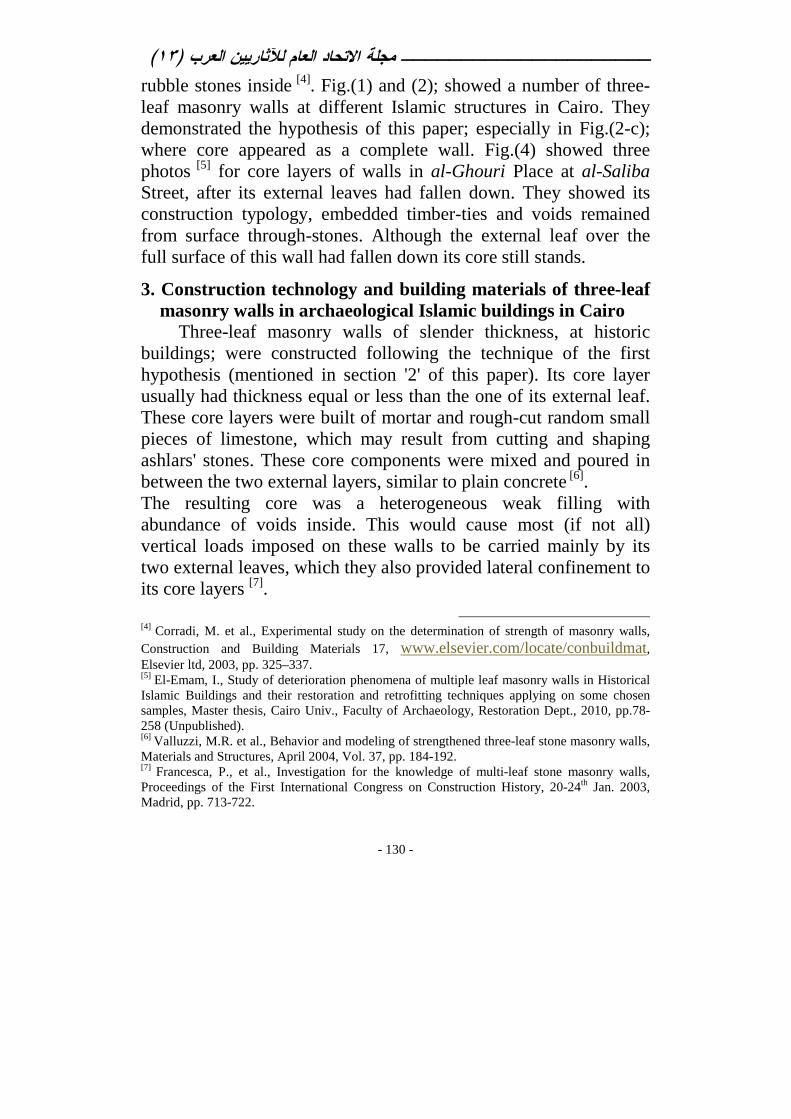
rubble stones inside [4]. Fig.(1) and (2); showed a number of three-leaf masonry walls at different Islamic structures in Cairo. They demonstrated the hypothesis of this paper; especially in Fig.(2-c); where core appeared as a complete wall. Fig.(4) showed three photos [5] for core layers of walls in al-Ghouri Place at al-Saliba Street, after its external leaves had fallen down. They showed its construction typology, embedded timber-ties and voids remained from surface through-stones. Although the external leaf over the full surface of this wall had fallen down its core still stands.
3. Construction technology and building materials of three-leaf masonry walls in archaeological Islamic buildings in Cairo
Three-leaf masonry walls of slender thickness, at historic buildings; were constructed following the technique of the first hypothesis (mentioned in section '2' of this paper). Its core layer usually had thickness equal or less than the one of its external leaf. These core layers were built of mortar and rough-cut random small pieces of limestone, which may result from cutting and shaping ashlars' stones. These core components were mixed and poured in between the two external layers, similar to plain concrete [6]. The resulting core was a heterogeneous weak filling with abundance of voids inside. This would cause most (if not all) vertical loads imposed on these walls to be carried mainly by its two external leaves, which they also provided lateral confinement to its core layers [7].
[4] Corradi, M. et al., Experimental study on the determination of strength of masonry walls, Construction and Building Materials 17, www.elsevier.com/locate/conbuildmat, Elsevier ltd, 2003, pp. 325–337. [5] El-Emam, I., Study of deterioration phenomena of multiple leaf masonry walls in Historical Islamic Buildings and their restoration and retrofitting techniques applying on some chosen samples, Master thesis, Cairo Univ., Faculty of Archaeology, Restoration Dept., 2010, pp.78-258 (Unpublished). [6] Valluzzi, M.R. et al., Behavior and modeling of strengthened three-leaf stone masonry walls, Materials and Structures, April 2004, Vol. 37, pp. 184-192. [7] Francesca, P., et al., Investigation for the knowledge of multi-leaf stone masonry walls, Proceedings of the First International Congress on Construction History, 20-24th Jan. 2003, Madrid, pp. 713-722.
)١٣( مجلة الاتحاد العام للآثاريين العرب ـــــــــــــــــــــ
- 131 -
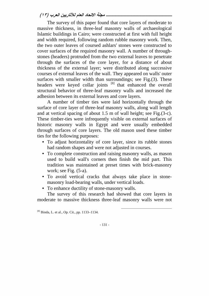
The survey of this paper found that core layers of moderate to massive thickness, in three-leaf masonry walls of archaeological Islamic buildings in Cairo; were constructed at first with full height and width required, following random rubble masonry work. Then, the two outer leaves of coursed ashlars' stones were constructed to cover surfaces of the required masonry wall. A number of through-stones (headers) protruded from the two external leaves to penetrate through the surfaces of the core layer, for a distance of about thickness of the external layer; were distributed along successive courses of external leaves of the wall. They appeared on walls' outer surfaces with smaller width than surroundings; see Fig.(3). These headers were keyed collar joints [8] that enhanced the overall structural behavior of three-leaf masonry walls and increased the adhesion between its external leaves and core layers.
A number of timber ties were laid horizontally through the surface of core layer of three-leaf masonry walls, along wall length and at vertical spacing of about 1.5 m of wall height; see Fig.(3-c). These timber-ties were infrequently visible on external surfaces of historic masonry walls in Egypt and were usually embedded through surfaces of core layers. The old mason used these timber ties for the following purposes:
• To adjust horizontality of core layer, since its rubble stones had random shapes and were not adjusted in courses.
• To complete construction and raising masonry walls, as mason used to build wall's corners then finish the mid part. This tradition was maintained at preset times with brick-masonry work; see Fig. (5-a).
• To avoid vertical cracks that always take place in stone-masonry load-bearing walls, under vertical loads.
• To enhance ductility of stone-masonry walls. The survey of this research had showed that core layers in
moderate to massive thickness three-leaf masonry walls were not
[8] Binda, L. et al., Op. Cit., pp. 1133–1134.
)١٣( مجلة الاتحاد العام للآثاريين العرب ـــــــــــــــــــــ
- 132 -
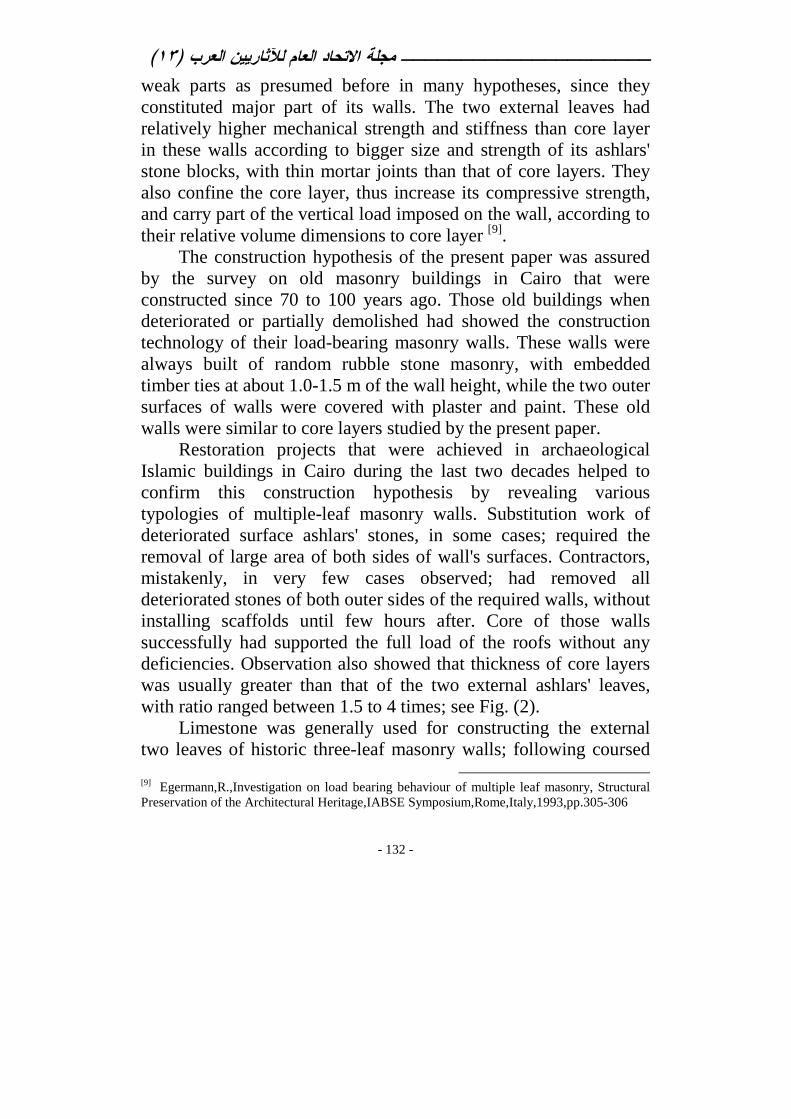
weak parts as presumed before in many hypotheses, since they constituted major part of its walls. The two external leaves had relatively higher mechanical strength and stiffness than core layer in these walls according to bigger size and strength of its ashlars' stone blocks, with thin mortar joints than that of core layers. They also confine the core layer, thus increase its compressive strength, and carry part of the vertical load imposed on the wall, according to their relative volume dimensions to core layer [9].
The construction hypothesis of the present paper was assured by the survey on old masonry buildings in Cairo that were constructed since 70 to 100 years ago. Those old buildings when deteriorated or partially demolished had showed the construction technology of their load-bearing masonry walls. These walls were always built of random rubble stone masonry, with embedded timber ties at about 1.0-1.5 m of the wall height, while the two outer surfaces of walls were covered with plaster and paint. These old walls were similar to core layers studied by the present paper.
Restoration projects that were achieved in archaeological Islamic buildings in Cairo during the last two decades helped to confirm this construction hypothesis by revealing various typologies of multiple-leaf masonry walls. Substitution work of deteriorated surface ashlars' stones, in some cases; required the removal of large area of both sides of wall's surfaces. Contractors, mistakenly, in very few cases observed; had removed all deteriorated stones of both outer sides of the required walls, without installing scaffolds until few hours after. Core of those walls successfully had supported the full load of the roofs without any deficiencies. Observation also showed that thickness of core layers was usually greater than that of the two external ashlars' leaves, with ratio ranged between 1.5 to 4 times; see Fig. (2).
Limestone was generally used for constructing the external two leaves of historic three-leaf masonry walls; following coursed
[9] Egermann,R.,Investigation on load bearing behaviour of multiple leaf masonry, Structural Preservation of the Architectural Heritage,IABSE Symposium,Rome,Italy,1993,pp.305-306

)١٣( مجلة الاتحاد العام للآثاريين العرب ـــــــــــــــــــــ
- 133 -
ashlars facing stone-masonry system, while its core layers were constructed following random un-coursed rubble masonry system. Stone blocks were cut and shaped of nearly uniform sizes, with five faces that were finely dressed. Accordingly, bed and head mortar joints of external leaves in the three-leaf masonry walls were uniform and thin (about 1.0 cm). Random rubbles of broken stones and/or broken red-bricks were used to build core layer following uncoursed random masonry. Profusion of lime and/or gypsum based mortar binds the rubbles together, fills the gaps among them and adheres core layer with the surrounding two outer leaves [10]. Timber ties, of about 10x15 cm cross-section, 1.5 to 3.0 m long, and of local or available wooden types; were inserted through the surfaces of the core layer. They were non-uniformly distributed on the surface of the core; as described before in this section. They were also located where openings of doors or windows through walls, as lintels, and at timber roof borders, as pad beams [11]; see Fig.(3-c). 4. Brief historic review and background of using timber-ties in
reinforcing masonry walls Unreinforced masonry (URM) work always suffers from very
low tensile strength and low ductility. Consequently, URM structures usually exhibit various types of cracking patterns, the most common and simple types are the vertical cracks that caused by excessive vertical loads, dilation and creep [12]. Attempts to strengthen URM structures against serious cracking phenomena, especially ones caused by earthquakes; dated back to the ancient times. The most prominent technique was introduced by using Timber Frame (T-F) masonry system, which had been found utilized since the Bronze Age and the early Roman Times at
[10] Principles of architectural design and urban planning during different Islamic Eras, Organization of Islamic Capitals and Cities, Jeddah, Saudi Arabia, 1992, pp. 451-456. [11] Ibid., pp. 195-197. [12] Vissilia, A. and Villi, M., Adobe and Timber Ties as Main Construction Materials for an Historic Greek Dwelling, International Journal of Architectural Heritage, 4: Taylor & Francis Group, 2010, pp. 295–319.

)١٣( مجلة الاتحاد العام للآثاريين العرب ـــــــــــــــــــــ
- 134 -
seismic prone regions in many foreign countries, such as Greece, Italy and Turkey [13]. The presence and development of T-F masonry were closely related to earthquakes, as it helped to enhance ductility of masonry work and to resist internal tensile stresses. The principle of this technique was simply aimed to insert timber ties in the direction of possible high tensile forces that were produced at critical locations of masonry walls under permanent vertical loads and other severe actions (e.g. earthquakes). The T-F construction technique was initiated with only horizontal timber-ties that lied along walls' length. Then continued with complete horizontal timber-frames of two long beams that extended along the full length of the two sides of masonry walls and connected periodically with timber posts through wall's thickness (laterally) [14]; see Fig. (5: b and c). The T-F system had undergone several improvements during its long history, primarily aiming to enhance its earthquake resistance in seismic prone areas. The most essential sophistication and maturity introduced in it was the use of diagonal bracing members along with the surrounding timber frame [15]. For this type of T-F system, a 3D-wooden frame that consisted of ‘beams’ (lintels), ‘columns’ (posts) and diagonal braces; were constructed at first and then URM work (usually of brick work) were inserted to fill the voids among timber frame elements [16]; see Fig. (6). In some few cases, X-type diagonals were used in the 3D-timber frame as bracing for horizontal and vertical elements, instead of simple diagonals. Timber connections were made by means of iron nails and ties. However, these elements were very deficient by corrosion [17].
[13] Kouris, L.A.S. and Kappos, A.J., Detailed and simplified non-linear models for timber-framed masonry structures, Journal of Cultural Heritage (Article in Press), www.elsevier.com/locate/culther, Elsevier ltd, 2011, p.1-6. [14] Vissilia, A. and Villi, M.,Op. Cit., pp. 295–319. [15] Kouris, L.A.S. and Kappos, A.J., Op.Cit., p. 2. [16] Vissilia, A. and Villi, M., Op. Cit., pp. 295–319. [17] Kouris, L.A.S. and Kappos, A.J., Op. Cit. pp.2-5.
)١٣( مجلة الاتحاد العام للآثاريين العرب ـــــــــــــــــــــ
- 135 -
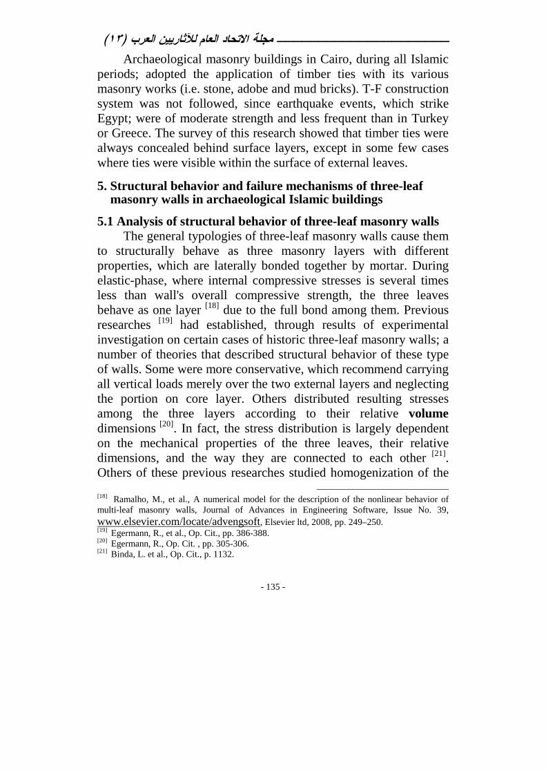
Archaeological masonry buildings in Cairo, during all Islamic periods; adopted the application of timber ties with its various masonry works (i.e. stone, adobe and mud bricks). T-F construction system was not followed, since earthquake events, which strike Egypt; were of moderate strength and less frequent than in Turkey or Greece. The survey of this research showed that timber ties were always concealed behind surface layers, except in some few cases where ties were visible within the surface of external leaves.
5. Structural behavior and failure mechanisms of three-leaf masonry walls in archaeological Islamic buildings
5.1 Analysis of structural behavior of three-leaf masonry walls The general typologies of three-leaf masonry walls cause them
to structurally behave as three masonry layers with different properties, which are laterally bonded together by mortar. During elastic-phase, where internal compressive stresses is several times less than wall's overall compressive strength, the three leaves behave as one layer [18] due to the full bond among them. Previous researches [19] had established, through results of experimental investigation on certain cases of historic three-leaf masonry walls; a number of theories that described structural behavior of these type of walls. Some were more conservative, which recommend carrying all vertical loads merely over the two external layers and neglecting the portion on core layer. Others distributed resulting stresses among the three layers according to their relative volume dimensions [20]. In fact, the stress distribution is largely dependent on the mechanical properties of the three leaves, their relative dimensions, and the way they are connected to each other [21]. Others of these previous researches studied homogenization of the
[18] Ramalho, M., et al., A numerical model for the description of the nonlinear behavior of multi-leaf masonry walls, Journal of Advances in Engineering Software, Issue No. 39, www.elsevier.com/locate/advengsoft, Elsevier ltd, 2008, pp. 249–250. [19] Egermann, R., et al., Op. Cit., pp. 386-388. [20] Egermann, R., Op. Cit. , pp. 305-306. [21] Binda, L. et al., Op. Cit., p. 1132.

)١٣( مجلة الاتحاد العام للآثاريين العرب ـــــــــــــــــــــ
- 136 -
multiple-leaf walls using properties of its components, in addition to their failure mechanisms. They derived equations that estimated wall's overall strength from mechanical properties and volume ratios of its three leaves.
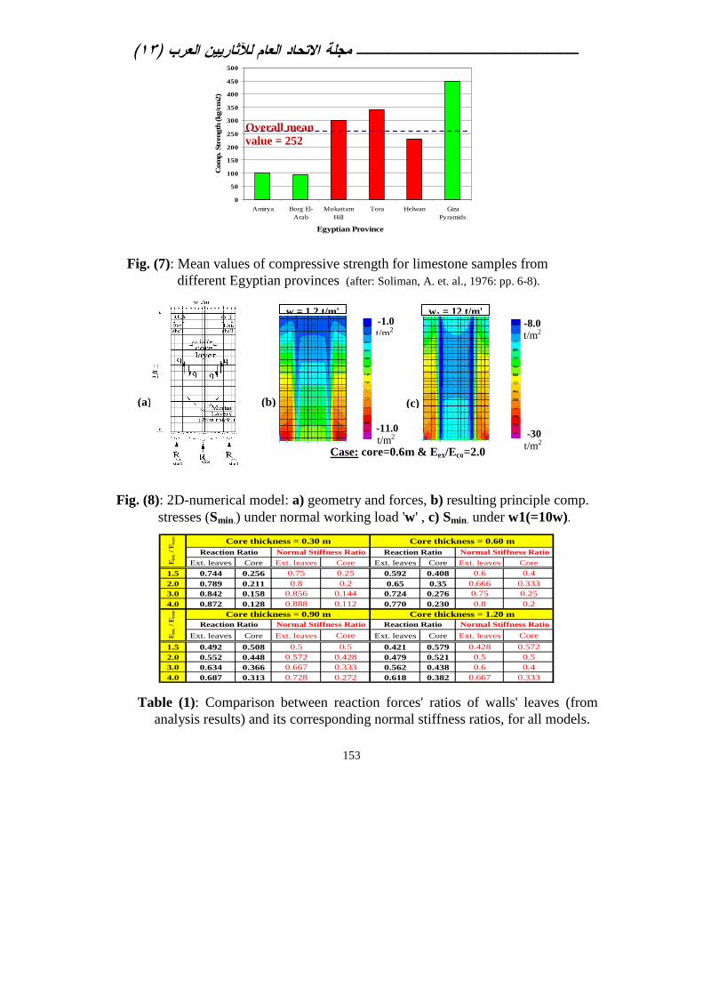
This paper studied analytically, using numerical modeling technique that utilizes Finite Element Method (F.E.M.); three-leaf masonry walls in archaeological Islamic structures in Cairo, with its various dimensions and mechanical properties of its core layers. Slender, moderate and massive thickness of three-leaf masonry walls were analyzed using one of the well known computer package[22] utilized in the field of structural engineering. This investigation aimed to determine for each layer its shared carrying capacity from the overall vertical loads imposed on the wall. This would evaluate the construction theory for moderate and wide thickness three-leaf masonry walls and emphasize on the main structural roles of core layer, apart from being merely a weak infill, as presumed before. A number of 2D-numerical models were prepared; using 4-nodes thick Shell-elements of the applied software. For all these models, the two external leaves were assumed to be built of ashlars' limestone masonry, while the core layer was built of random rubble of broken limestone in profusion of mortar. These three leaves were bonded together by adhering mortar layers in-between; see Fig.(8-a). Only straight connection between external leaves and core layer was studied in this paper (i.e. without shear keys in Fig. 3-b). The survey on archaeological Islamic structures in Cairo had showed a good similarity among wide range of three-leaf masonry walls; both in building materials and construction technology. Thus, input-data for properties of building materials were assigned to numerical models in accordance to average results of previous experimental works [23], [24] on
[22] SAP2000, Version 10.1.0, CSi Analysis Reference Manual for SAP2000, Berkeley, California, USA: Computers and Structures Inc., 2006. [23] Amin, Y., Analysis and Assessment of Structural Deficiencies in Historical Islamic Religious Buildings from Bahri Mamluk Period and the Possible Scientific Methods for Conservation and Restoration with Application on the Madrasa of Umm Al-Sultan Sha’ban in=

)١٣( مجلة الاتحاد العام للآثاريين العرب ـــــــــــــــــــــ
- 137 -
different masonry constituents (i.e. limestone and lime-based mortars), which were extracted from a number of archaeological Islamic buildings in Cairo. They covered a wide range and provided a good example for these building materials of the studied three-leaf stone masonry walls. Also, the Egyptian Code of Masonry [25]
(ECM) provided a guide Table (No. 2-9) that contained average values of limestone properties in Egypt. The adopted mean values for properties of limestone and mortar, from these references; were appropriate for the general investigation conducted in this paper.
According to Soliman et al. [26], who carried a wide experi-mental investigation on limestone samples taken from main quarries in Egypt; the researcher derived the Chart in Fig.(7). Hence; the mean values of compressive strength for lime-stones in Cairo ranged between 230 and 340 kg/cm2 (23-34 MPa), with average value (fb) = 285 kg/cm2. Range of its bulk density was (ρ) = 1.8 - 2.3 ton/m3 and porosity range was = 11-16%. These results represented normal condition for limestone in Cairo. Another experimental investigation [27] on limestone samples, which were taken from an archaeological Islamic building in Cairo; showed compressive strength ranged between 190 and 326 kg/cm2 (i.e. average value fb = 258 kg/cm2). Range of its bulk density (ρ) = 2.2-2.4 ton/m3 and its porosity = 5-12%. For samples of historic mortars, range of density was (ρ') = 1.2-1.5 ton/m3, and range of porosity was = 5-17%. These results represented aging condition for limestone and mortar, since they were taken from historic walls. Results of the previous two experimental works on limestone
=Cairo, Ph.D. Thesis, Cairo University, Faculty of Archaeology, Conservation Dept., 2004, pp. 237-245, (Unpublished). [24] Soliman, A., Tahlawi, M. R. and Goma'a, W. A., Data Book of Egyptian Limestones, Geotechnical Specifications, Mining and Metallurgical department, Assiut Univ., Assiut, 1972, pp. 6-8. [25] ECM, Egyptian Code of Practice for Design and Execution of Masonry Buildings, Ministry of Housing, Public Utilities and Building Development, Code No. 204, Cairo, 2005, p. 31 (in Arabic). [26] Soliman, A., et al., pp. 6-8. [27] Amin, Y., Op. Cit., pp. 219-223.
)١٣( مجلة الاتحاد العام للآثاريين العرب ـــــــــــــــــــــ
- 138 -
samples from Cairo were relevant and consistent. They also matched with ECM Code [28] guide values of limestone properties, which are: fb = 280 kg/cm2 and ρ = 2.16 t/m3. Accordingly, the researcher assigned the following data of material properties for all conducted numerical models in this research: • Average density for masonry work of external leaves, core layers
and adhering mortar layers (respectively) = 2.2, 2 and 1.6 ton/m3. • Range of compressive strength for limestone (fb) = 170 - 250
kg/cm2 (17-25 MPa), while for mortar (fm) = 12-20 kg/cm2. • Mean value of compressive strength (fk) for ashlars' limestone
masonry of the two external leaves was estimated = 57 kg/cm2 according to Edgell et al. [29], while according to ECM Code [30], Table (2-12-b), it was estimated (fk) = 68 kg/cm2.
• Young's modulus of elasticity (E) of external leaves [31] = (700 ~ 900)x fk
These values were compared with results of previous experimental researches [32], [33] conducted on masonry walls that were built of limestone with (rather) similar properties of the ones at Islamic buildings in Cairo (e.g. Noto Italian limestone). Mean compressive strength for external leaves of Noto [34] limestone (fk-1) = 87 kg/cm2, and of core layer (fk-2) = 41 kg/cm2.
From these experimental results and the previous estimated values, final mechanical properties of both external and core layers, of the studied three-leaf masonry walls at historic Islamic buildings; were considered as following:
[28] ECM, Op. Cit., Table (2-9), p. 31. [29] Edgell, G.J., et al., Characteristic compressive strength of UK masonry: a review, Masonry-9, Proceedings of the 6th British International Masonry Conference, Nov. 2002, Ed. H.W.H. West, Society Stoke on Trent Pub., UK, 2002, ( fk = 0.5 fb
0.75 fm 0.25), pp. 109-110. [30] ECM, Op. Cit., p. 38. [31] Ibid., p. 39. [32] Binda, L. et al., Op. Cit., pp. 1132-1148. [33] Valluzzi, M.R. et al., Op. Cit., pp. 186-189. [34] Binda, L. et al., Op. Cit., p. 1138.

)١٣( مجلة الاتحاد العام للآثاريين العرب ـــــــــــــــــــــ
- 139 -
• Mean compressive strength of external leaves (fk-1) and core layer (fk-2) = 60 and 30 kg/cm2 (respectively).
• Young's modulus of elasticity assigned to external leaves of ashlars' limestone masonry (Eext) = 4x10⁵ ton/m2, and for adhering mortar layers (Em) = 1x10⁴ ton/m2.
• Poisson's ratio (ν) for the three leaves of walls = 0.25, and for the adhering mortar layers = 0.30.
5.1.1 Structural study across wall's cross-section: Four main 2D-numerical models were structurally analyzed in
elastic phase. They represented various cases of three-leaf masonry walls possibly found in archaeological Islamic buildings in Cairo. It was aimed to study the portion of load resisted by each layer under the overall vertical imposed load on the wall. Dimensions of wythes (leaves) were taken according to the results of the survey on these walls. For all models; thickness of each external leaf was considered (text) = 0.3 m and the adhering mortar layer (tm) = 2 cm, while core layer thickness (tcore) was variable; see Fig.(8-a). It was assigned as a ratio = 1, 2, 3 and 4 of the external leaf thickness, which composed the four main models. Height of all walls were taken = 3.0 m. Also, variable structural conditions were assigned to core layer through its Modulus of elasticity (Ecore); which were assigned as a ratio of the corresponding one of the external leaf (Eext). Four cases of core layer were considered for each model, through ratios Eext / Ecore = 1.5, 2, 3 and 4; see Table (1).
Working Stress Design Method (WSDM) according to ECM Code [35] were implemented in structural evaluation of the models. Each model represented one meter strip of the studied three-leaf masonry walls. They were vertically loaded by its own weight and average reaction load of one flat timber roof (w). This roof's load (w) was based on Pitch-Pine timber joists (10x15cm cross-section and density = 0.6 t/m3), carrying traditional timber plates and flooring layers. This roof was assumed covering a room of 5.0m
[35] ECM, Op. Cit., pp. 41-63.

)١٣( مجلة الاتحاد العام للآثاريين العرب ـــــــــــــــــــــ
- 140 -
span, as an average span observed in the survey, and loaded by live load [36] = 300 kg/m2. The reaction load of this one-way timber roof was 1.6 tons for every 1.0m strip of the studied load-bearing wall. This superimposed load was uniformly distributed on the wall's width, which would result on different values for each model. Their average value was (w) = 1.2 t/m' (working loads), which was assigned to each model for differentiating among them on constant bases; see Fig.(8-b).
The 16 numerical models were analyzed under the previous loads and materials' data, using simple elastic and static analysis. We studied the resulting reaction forces and various stresses of the three layers. Table (1) showed ratios between reaction forces of the two external leaves (together) and the core layer, for all the models. The table compared these ratios with the ratios of the multiplication of Young's modulus (E) times thickness (t) of the same two parts of the models. Both ratios were almost identical. Consequently, all models showed that each layer carried part of the overall load on the masonry wall, proportioned to (E t) ratio of this layer. This ratio represents the normal stiffness of the layer, since height of all layers is constant. Resulting tensile stresses developed in wall's section were negligible. Shear stresses between layers were significant, which directions were designated by arrows and letter 'q' in Fig.(8-a). Distribution of principle compressive stresses in wall's section was also showed in Fig. (8-b). Higher stresses were located at the two external wythes than core, with maximum value = -11 t/m2, which was very safe (fk-1=600 t/m2 and fk-2=300 t/m2). Increasing the impose load on wall (w) to higher values (from 2 till 10 times), we found the previous resulting stresses still safe; see Fig.(8-c).
Analyzing data in Table (1) had showed that external layers usually carry the greater portion of the overall load imposed on the wall than the core, in case of slender and moderate thickness three-
[36] ECL, Egyptian Code of Practice for Loads in Structural and Masonry Works, Ministry of Housing, Public Utilities and Building Development, Code No. 201, Cairo, Sept. 2008, pp. 30-32, (in Arabic).

)١٣( مجلة الاتحاد العام للآثاريين العرب ـــــــــــــــــــــ
- 141 -
leaf walls. For thick and massive walls, core thickness exceeds outer leaves' thickness with several times. In these cases, besides using higher strength masonry for core layer (i.e. Ecore is higher), the portion of load carried by core layer increases, till it exceeds that is carried by external leaves (i.e. Max. core ratio = 0.579 in Table 1). Fig.(9) showed the ratio of the overall load on wall that is carried by core layer, according to (E t) ratio; as explained before.
Shear stress (q) at interface mortar plane between core and external layers; ranged between 1.02 and 2.51 ton/m2. Previous experimental shear test [37] on similar three-leaf specimens, showed its shear strength =17 t/m2 (0.17 N/mm2); which indicated the safety of resulting shear stresses (q) in analyzed models.
Finally, previous analyses showed that own weight of three-leaf walls played the major role in its walls' stability and had more influence on its various developed stresses than that caused by imposed vertical loads. Also, core layer when fully bonded inside the three-leaf wall with its external leaves (during elastic-phase); carried less than being separated from them, while the contrary occurred to external leaves (i.e. carried more). 5.1.2 Structural study along wall's length:
3D-numerical models; using 8-nodes Solid-elements of the applied software, were prepared, with the same materials' data. Dimensions of wall's model were: 6.0m long, 3.0m high and 1.2m width; see Fig.(10-a). They studied the resulting stresses in all layers along the direction of the wall's length. We chose the previous second case of wall, which core's thick.= 0.6 m and Young's Modulus for core was taken (Ecore) = 2x10⁵ t/m2. Mortar layers between each external leaf and core layer were also introd-uced in the model. The assigned properties of mortar layers were: Young's Modulus (Em) = 1x10⁴ t/m2 and density (ρ') = 1.6 t/m3. The model was loaded by surface pressure 'w1'
(*) = 12 t/m2 (working
[37] Binda, L. et al., Op. Cit., p. 1135-1136. (*) This wall model was considered carrying walls of two upper floors, and three roofs load (w). Upper floor walls were 3.0m high and 0.9m thick., with average density = 2.0 t/m3.

)١٣( مجلة الاتحاد العام للآثاريين العرب ـــــــــــــــــــــ
- 142 -
loads); besides the own weight of wall. Fig.(11-a) showed contours of tensile stresses along wall's length direction (Syy), while Fig.(11-b) showed corresponding compressive stresses (Syy) in core layer. Fig.(12) showed vertical compressive stresses in the full model.
Masonry walls generally exhibit high local compressive stresses in the region beneath roofs, where vertical loads are just applied. Going down the wall, these compressive stresses are distributed over greater area of wall's cross-section. This spreading out of vertical stresses creates principal stresses including tension which can lead to vertical cracks [38].
The general typology of three-leaf masonry walls is usually composed of two strong external leaves and a weaker core layer in-between. Under vertical loads and during elastic phase; stronger external leaves restrict the longitudinal expansion of core along walls' length and its raised vertical contraction, due to its weaker mechanical properties than the external leaves. Fig.(10-b) showed the elastic deformed shape of the model in X-Z plane. This restriction is provided through bond of mortar that adhere core layer with its surrounding leaves. These actions generate compression in core layer and tensile stresses in upper side of external two leaves. The previous stress analysis was summarized in Fig.(13)
Previous experimental works [39] agreed with these analysis results. They showed that external layers apply a restraint action on the internal core and, at the same time, the dilation of the core applies a lateral thrust to the external layers.
5.2 Failure mechanisms of three-leaf masonry walls Unreinforced masonry walls that follow three-leaf construction
system; always suffer from lack of ductility, which cause soon cracking, progressive failure and brittle collapse mechanisms [40].
[38] Drysdale, G., Hamid, A. and Baker, R., Masonry Structures: Behavior and Design, The Masonry Society (TMS) Pub., 2nd Ed., Boulder, Colorado, USA, 1999, p. 381. [39] Valluzzi, M.R. et. al., Op. Cit., pp. 188-189. [40] Binda, L. et al., Op. Cit., p. 1132.

)١٣( مجلة الاتحاد العام للآثاريين العرب ـــــــــــــــــــــ
- 143 -
Previous experimental researches [41] showed structural deficiencies of these walls under vertical loads usually start with shear cracks, of either vertical or sub-vertical pattern, in the interface mortar layers that bond core with external leaves. These cracks are mostly located in the transverse direction (i.e. wall's cross-section). They continue till out-of-plane detachment [42] from core layer and buckling of external leaves take place. Failure of the external layers is caused by combined bending and compressive stresses. At that stage, the ratio between the axial loads carried by the core and external layers was estimated [43] around (1:5). Vice versa, when the internal core is stiffer than the outer layers, a brittle collapse of the wall can occur, caused by the compressive failure of the core, with the consequent sudden failure of the outer layers. At collapse, the ratio between the compressive stresses in the internal and external layers was estimated around (7:3). Other structural problems exhibited in these walls may result from the poor or absent connections between the leaves, the weak strength of core layer, and/or the deterioration building materials. The following conclusive remarks were derived from the previous experimental research [44], regarding failure mechanisms of three-leaf masonry wallets: • Triplet shear test on wallets showed that failure in case of straight
collar joints (i.e. no through stones) was quite brittle without showing any residual strength. While, keyed collar joints exhibited less brittle behavior than the straight case.
• Straight connection failed in shear with straight vertical cracks at both interface mortar planes between core and external leaves. Keyed connection failed in shear with inclined (diffused) crack pattern at both mortar interface and core layer. At the ultimate stage, full separation between the three leaves occurred.
[41] Binda, L. et al., Op. Cit., pp. 1135-1136. [42] Valluzzi, M.R. et. al., Op. Cit., pp. 184-192. [43] Ibid., pp. 188-189. [44] Binda, L. et al., Op. Cit., p. 1134-1140.

)١٣( مجلة الاتحاد العام للآثاريين العرب ـــــــــــــــــــــ
- 144 -
• Compression test on three-leaf wallets showed that keyed collar joints increase the overall strength of the wall for about 10% higher than the straight joints (i.e. without connections).
• Larger vertical strains were recorded in the outer-leaves than in the inner-leaves for tested wallets with straight collar joints. On the contrary, the case of wallets with keyed collar joints recorded rather similar vertical strains in the different leaves. This emphasizes on the role of shear keys (i.e. through stones) in obtaining a uniform distribution of strains among wall's leaves.
• Compressive strength of outer leaf, when tested alone as a single-leaf; was about 40% higher than its corresponding strength as being part in a three-leaf wall, due to outward thrust from core.
• Compression failure, in case of straight connections; occurred due to the development of several vertical cracks in the outer-leaves while the inner-leaf was practically undamaged. In case of walls with keyed connections, the outer-leaves exhibited a more severe and diffuse crack pattern accompanied by several vertical cracks developed in the inner-leaf before failure occurred.
6. The use of embedded timber ties in restoration and
retrofitting of historic three-leaf masonry walls
6.1 Main mechanical properties of timber ties Wood is anisotropic material owing to its complex biological
structure. It has independent and different mechanical properties in the three directions of perpendicular axes: longitudinal, radial and tangential. The longitudinal axis 'L ' is parallel to the grain; the radial axis 'R' is perpendicular to the grain in the radial direction (normal to the growth rings); and the tangential axis 'T' is perpendicular to the grain but tangent to the growth rings. The mechanical properties are significantly influenced by the direction relative to fiber and growth ring orientation. These properties depend on natural defects beside other several factors including:

)١٣( مجلة الاتحاد العام للآثاريين العرب ـــــــــــــــــــــ
- 145 -
physical properties, density, moisture content and duration of the applied loads [45]. Tensile strength of clear wood, parallel to the grain; is much higher than its compressive strength, since compression causes buckling or plastic crushing of the fibers. Besides, higher stiffness and strength properties are provided in the parallel to grain direction (L) than the perpendicular directions (R and T). However, the opposite of this previous behavior is found when timber contains knots and/or distorted grains, since they cause tensile failure due to shear between fibers.
Sawn wood, in architectural dimensions; usually contains defects of various kinds, such as: knots, slope of grain, shakes and checks, decay, pockets, etc. Knots are considered the main serious defects since they greatly reduce strength and are usually present in a considerable numbers within a piece of timber. They have a much greater effect on strength in axial tension than in axial compression (i.e. short-column), and the effects on bending are somehow less than those in axial tension [46].
The mechanical properties of customary timber ties in its longitudinal axis, in general; are much higher than limestone masonry work in archaeological Islamic buildings in Cairo. Previous experimental researches [47] on a number of samples of structural timber samples of nine different wooden species (e.g. Oak, Pine, Beech, Larch, etc.); showed that range of Young's Modulus at 12% moisture content; was (EL) = (1.1-1.53) x106 t/m2 (11-15.3 GPa) in the longitudinal axis 'L' direction, while in 'R' direction range was (ER) = (0.76-1.31) x105 t/m2. The average ratios among moduli were (EL : ER : ET) ≈ (20 : 1.6 : 1). Range of
[45] Calderoni, B., et al., Flexural and shear behaviour of ancient wooden beams: Experimental and theoretical evaluation, Journal of Engineering Structures, Issue No. 28, Elsevier ltd, www.elsevier.com/locate/engstruct, 2006, pp. 729-744. [46] Vissilia, A. and Villi, M.,Op. Cit., pp. 295–319. [47] Migliore, R. and Ramundo, F., Experimental testing for the identification of mechanical characteristics of ancient timber elements, Proceedings of the 1st International Conference PROHITECH09 'Protection of Historical Buildings', Vol. 1, Mazzolani, F.M. Editor, 22-24 June 2009, Rome, Italy, 2009, pp. 375-380.

)١٣( مجلة الاتحاد العام للآثاريين العرب ـــــــــــــــــــــ
- 146 -
corresponding tensile strength of these timber samples was = 150 -400 kg/cm2 (15-40 MPa) in 'L' direction and less than 0.5 MPa in 'R' direction. While in compression they were 20-40 MPa in 'L' dir. and 5 MPa 'R' dir. These values provided indications for average mechanical properties of timber elements.
6.2 The use of horizontal timber-ties in the restoration and retrofitting of historic three-leaf masonry walls The 3D-numerical model of Solid elements, described in
section 5.1.2 of this paper; was modified to introduce two hori-zontal timber ties at the location of high tensile stresses; as Fig.(11-a). Fig.(14) showed perspective view for this 3D-model. Average timber properties, which were considered based on section 6.1 of this paper; were: EL=1.2x10⁶ t/m2, density (ρ) = 0.6 t/m3 and Poisson's ratio (ν) = 0.3. Under previous working vertical loads (w1), the two timber ties attracted almost all of the high tensile stresses from the surrounding stone masonry of outer leaves. Accordingly; the maximum tensile stresses (Syy) in the external leaves was reduced to less than +1.0 t/m2; which is 75% lesser than the previous resulted stresses (without timber ties). Fig.(15) showed resulted tensile stress contours in the two timber ties under normal working loads (w1), which range = 0 to +15 t/m2. The maximum stress is 1% of the expected tensile strength of timber (refer to sec. 6.1 of this paper), which is very safe. This numerical study showed the great enhancement in structural behavior of three-leaf walls by inserting horizontal timber ties at surface of the upper part of the external two leaves; where high tensile stresses were located along wall length. These ties are considered conservative reinforcing elements, which the predecessor masons had applied with all types of masonry works. The present results of structural analysis works matched with timber ties' locations and use at various historic masonry works; reviewed in section 4 of this paper.
The survey on archaeological Islamic buildings in Cairo of the present research; revealed that horizontal timber ties were always

)١٣( مجلة الاتحاد العام للآثاريين العرب ـــــــــــــــــــــ
- 147 -
concealed under surface plaster or ashlars' stones of wall's surface. Except for few cases, timber ties were rarely seen on the surface of any stone masonry walls; especially façades (either exterior or interior). On the contrary, timber ties were usually visible on the surface of masonry walls in historic structures of regional and international countries; see Figures: (3-c), (4) and (5).
6.3 The technique of reinforcing three-leaf masonry walls with horizontal timber ties Timber ties can be used to strengthen deficient three-leaf
masonry walls in historic buildings; at locations of structural vertical cracks and/or whenever dismantling of external layer(s) are needed to restore the core layer or replace some of its ashlars' stones. The results of structural analysis works of the present paper direct to place timber ties within the surface of the external two leaves and at its upper side; following typical detail of case 'a' at Fig.(16). Accordingly, a timber tie of cross-section 6x10 inches (15x25 cm) and 1.5-3.0 m long should be inserted through one of the upper courses of the external leaf of the wall; at about 0.5-0.7m down the roof. Mid of the tie would be located at crack of the walls. Placing timber ties may be continued downward at intervals of 1.5m; whenever crack extended. Timber ties would also be adhered to its surrounding masonry by strong conservative grout (i.e. lime mortar enhanced with additives as white cement). Fig.(17) showed an example of the previous restoration process; which was conducted to al-qibla façade wall at Jānbulāt Mosque (1797A.D.) in Cairo [48].
In case of severe vertical cracks that extend to core, besides No timber ties are visible on the surface of wall; typical detail of case 'b' in Fig.(16) can be implemented. Surface ashlars' stone would be dismantled; after being documented and numbered following relevant conservation rules. Two timber ties, connected with stainless-steel collars and mortise system; would be embedded
[48] El-Emam, I., Op. Cit., p. 5.

)١٣( مجلة الاتحاد العام للآثاريين العرب ـــــــــــــــــــــ
- 148 -
through core at crack location; following similar previous technique in case 'a'. The timber ties are concealed under finely dresses stone plates, of 10-15 cm thickness. This would preserve the original appearance of the façade wall and provide embedded timber ties that can resist possible tensile stresses. Fig.(18: a and b) showed restoration work of a core layer for an internal wall inside Mosque of Khayer Bak (1503 A.D.) in Cairo [49]. It was separated by vertical severe crack, along its entire height; after 1992 Earthquake in Cairo. Replacement of core with new compatible adobe bricks for deteriorated core materials; was conducted. Timber ties were distributed along wall length; at 1.50m intervals. Fine stainless-steel mesh was fixed on tie's surface, and then the full surface of wall was being plastered with lime-mortar. This mesh aimed to avoid shrinkage cracking caused by dimensional changes in timber. Timber ties should be treated against biological infections using suitable conservative techniques. It is also recommend using sound Pitch-Pine timber beams that were taken from old structures; since its dimensional changes are almost idle.
7. Conclusions and Recommendations The present paper studied various aspects of the three-leaf
masonry walls in archaeological Islamic buildings in Cairo and the use of timber ties for its restoration and retrofitting. The following conclusions can be drawn: 1) Survey on damaged walls in archaeological Islamic buildings in
Cairo had showed that core layer, in case of three-leaf masonry walls with moderate to wide thickness; were built following random rubble masonry work, and not by successive layering of stone and mortar in-between the two external ashlars' leaves; which was followed in constructing thin core walls.
2) These moderate to thick core layers in historic three-leaf walls, most probably; were constructed at first then the two external
[49] The two photos in Fig.(18) were shot by the researcher in 2006, as part of a survey work on restoration work of some Islamic historic buildings along Bab el-Wazir Route in Cairo.

)١٣( مجلة الاتحاد العام للآثاريين العرب ـــــــــــــــــــــ
- 149 -
ashlars' stone leaves were built to cover its surfaces. Thus, core layer is not usually a weak infill layer, which was mistakenly thought to be built mainly of mortar; with filler of small broken stones, similar to contemporary plain concrete.
3) Voids usually found in core layers of historic three-leaf walls may be attributed to its cracking phenomena and deterioration of its mortar, rather than its construction technique.
4) The two external leaves usually carry the greater part of overall applied vertical loads on the three-leaf masonry walls. Each of these external leaves can carry more loads if it stands alone than being part inside the three-leaf wall; due to additional flexure imposed to them from lateral thrust of core layer.
5) During elastic-phase, each leaf of the wall carried part of the overall vertical imposed loads proportioned to the ratio of the multiplication of its Young's Modulus (E) times its thickness (t).
6) Core layer of wide thickness and high stiffness can carry more than 50% of the overall vertical loads on its three-leaf wall.
7) keyed collar joints of the external leaves (i.e. through stones) enhance the overall structural behavior of three-leaf walls and raise its load-bearing capacity than straight connection.
8) Embedded timber ties were used with masonry works in Egypt and worldwide; since ancient ages. They were used to reinforce masonry walls against cracking, especially in seismic prone cities. The technique had developed progressively in Europe (e.g. Greece) till it reached to timber frame (T-F) structures.
9) Timber ties were usually concealed inside masonry walls and not visible on walls' surface; in most of Islamic architectural heritage in Cairo. This contradicts with historic buildings world-wide; as timber always visible on surface.
10) Analysis proved that ideal location for timber ties is at the top and within the surface of external leaves of the three-leaf walls.
11) Timber ties attract most of tensile forces developed in masonry walls under imposed vertical loads; thus help to prevent possible vertical cracks.
)١٣( مجلة الاتحاد العام للآثاريين العرب ـــــــــــــــــــــ
- 150 -
General recommendations can be summarized as follows: i. Restoration and retrofitting of historic three-leaf masonry walls
using timber ties provide a conservative and more efficient solution for serious vertical cracks than traditional injection work. The integration between more than one technique can provide better restoration work.
ii. More experimental and numerical researches are needed to study structural behavior and failure mechanisms of historic three-leaf masonry walls; especially walls with keyed collar joints. Physical models of walls should represent various types that were found in archaeological Islamic buildings in Cairo.
iii. Integrated experimental and numerical researches are needed to study the structural behavior and failure mechanisms of various structural elements of archaeological Islamic buildings in Egypt with their different materials, types (styles) and periods.
)١٣( مجلة الاتحاد العام للآثاريين العرب ـــــــــــــــــــــ
151
Fig. (3): Typical details of multiple-leaf masonry walls in archaeological Islamic buildings in Cairo: a) Elevation view of wall's façade, b) Cross-section view of the wall showing its three leaves, c) 3D-view50 of a masonry building showing timber tie-beams
50 Al-Garni et. al., Architectural Heritage at Kingdom of Saudi Arabia, Ministry of
Municipality and Rural Affairs Publication, Riyadh, Kingdom of Saudi Arabia, 2002, p.103
(a) (b) (c) (d)
Fig. (1): Examples of archaeological multiple-leaf masonry walls in Cairo: a) Dome of Amir Idekeen (1285AD, Ayyubid Era), b) Dome of Ashraf Khalil (1288AD), c) Qani-Bey Al-Rammah Madrasa (1503 AD), d) Remaining part of of Al-Ghuri Place at Saliba St. (1510 AD).
Fig. (2): Various typologies of three-leaf masonry walls in historic buildings: a) Slender wall, with arch filling, b) Wall of medium thickness, c) Medium to thick wall (all at Sultan Hassan Mosque), d) Thick (massive) wall (Sour Magra El-Oyoun).
Core Layer
External Layer
Through stones
(Headers)
(b) (d) (a) (c)
Medium wall
Slender wall
Medium to thick
Massive wall
Through stones
(Headers)
Timber-tie beam
Masonry Strip
Footing
(c) (b) (a)

)١٣( مجلة الاتحاد العام للآثاريين العرب ـــــــــــــــــــــ
152
Fig. (4): Three photos for core layer after falling down of all external layers, showing its construction typology, embedded timber-ties and voids remained from surface through-stones, in the remaining part of of Al-Ghuri Place at Al-Saliba Street (1505-1507 A.D.).
Fig. (5):Timber-tie system in masonry construction: a) A sketch of building contemporary brick-walls , b) 3D-view of adobe dwelling with timber ties, Greece, c) Adobe wall and timber ties, Greece, (b & c after: Vissilia, A. and Villi, M., 2010: p.301).
(c) (b) (a)
(b) (a)
(c)
Fig. (6): Timber Frame (T-F) construction system in Greece: a) T-F stone masonry building , b) T-F with diagonals (after: Kouris, L.A.S. and Kappos, A.J, 2011: p. 2).
(b) (a)
)١٣( مجلة الاتحاد العام للآثاريين العرب ـــــــــــــــــــــ
153
Fig. (7): Mean values of compressive strength for limestone samples from different Egyptian provinces (after: Soliman, A. et. al., 1976: pp. 6-8).
0
50
100
150
200
250
300
350
400
450
500
Amirya Borg El-Arab
MokattamHill
Tora Helwan GizaPyramids
Egyptian Province
Com
p. S
treng
th (kg
/cm
2)
Overall mean value = 252
Table (1): Comparison between reaction forces' ratios of walls' leaves (from analysis results) and its corresponding normal stiffness ratios, for all models.
Ext. leaves Core Ext. leaves Core Ext. leaves Core Ext. leaves Core
1.5 0.744 0.256 0.75 0.25 0.592 0.408 0.6 0.42.0 0.789 0.211 0.8 0.2 0.65 0.35 0.666 0.3333.0 0.842 0.158 0.856 0.144 0.724 0.276 0.75 0.254.0 0.872 0.128 0.888 0.112 0.770 0.230 0.8 0.2
Ext. leaves Core Ext. leaves Core Ext. leaves Core Ext. leaves Core
1.5 0.492 0.508 0.5 0.5 0.421 0.579 0.428 0.5722.0 0.552 0.448 0.572 0.428 0.479 0.521 0.5 0.53.0 0.634 0.366 0.667 0.333 0.562 0.438 0.6 0.44.0 0.687 0.313 0.728 0.272 0.618 0.382 0.667 0.333
Reaction Ratio Normal Stiffness Ratio
Reaction Ratio Normal Stiffness Ratio
Core thickness = 0.30 m
Eext
. / E
core Core thickness = 1.20 mReaction Ratio Normal Stiffness Ratio
Eext
. / E
core Core thickness = 0.60 m
Reaction Ratio Normal Stiffness Ratio
Core thickness = 0.90 m
Case: core=0.6m & Eex/Eco=2.0
(b) (c) (a)
w = 1.2 t/m' w1 = 12 t/m'
-11.0 t/m2
-1.0 t/m2
-30 t/m2
-8.0 t/m2
Fig. (8): 2D-numerical model: a) geometry and forces, b) resulting principle comp. stresses (Smin.) under normal working load 'w' , c) Smin. under w1(=10w).

)١٣( مجلة الاتحاد العام للآثاريين العرب ـــــــــــــــــــــ
154
Fig. (9): Ratio of load carried by core of a three-leaf masonry wall according to its thickness and elasticity modulus ratio with external layers (elastic phase).
Mortar interface
Ext. shell
Ext. shell
Core layer
(a)
(b)
Fig. (10): 3D-numerical model of three-leaf masonry wall: a) layers and geometry, b) deformed shape in Y-Z plane under normal working load (w1).
Fig. (11): Lateral stresses (Syy) under normal working load (w1): a) tensile stresses in external shells, b) corresponding compressive stresses in core layer.
Stress dir. (Szz)
(b) (a)
0.0 t/m2
-4.0 t/m2
0.0 t/m2
(Syy) (Syy)
Stress dir. +4.0 t/m2
t core = 1.20 m t core = 0.90 t core = 0.60 t core = 0.30
0
0.1
0.2
0.3
0.4
0.5
0.6
0.7
1.5 2.0 2.5 3.0 3.5 4.0Ra
tio o
f Loa
d Ca
rried
by
Core
E ext. / E core Ratio
Series
Series
Series
Series

)١٣( مجلة الاتحاد العام للآثاريين العرب ـــــــــــــــــــــ
155
Fig. (12): Vertical stresses (Szz) under normal working load (w1).
Fig. (13): Resulting stresses in different layers along wall's length under vertical working loads.
Fig. (14): Modified 3D-Solid Model with timber tie beam in external leaves (perspective view).
Fig. (15): Tensile stresses in timer tie beams along wall's length under vertical working loads (w).
-30.0 t/m2
0.0 t/m2
Timber-Tie
Fig. (16): Typical details of two different cases of restoration of three-leaf masonry walls using embedded timber tie technique.
Case (a)
+15.0 t/m2
0.0 t/m2
Case (b)

)١٣( مجلة الاتحاد العام للآثاريين العرب ـــــــــــــــــــــ
156
Fig. (18): Restoration of core layer by rebuilding deteriorated part and reinforcing it with timber ties; case 'b' in Fig.(16): a) general view, b) zoomed view (Mosque of Khayer Bak, 1503 A.D.).
Fig. (17): Restoration of interior façade wall following case 'a' of previous typical detail, Mosque of Jānbulāt, 1797A.D., in Cairo.
Spacing ≈1.50m
(b)
(a)