three-dimensionalgaussianbeam … scatteringfrom a periodicsequenceof bi-isotropicand materiallayers...
TRANSCRIPT

Progress In Electromagnetics Research B, Vol. 7, 53–73, 2008
THREE-DIMENSIONAL GAUSSIAN BEAMSCATTERING FROM A PERIODIC SEQUENCE OFBI-ISOTROPIC AND MATERIAL LAYERS
V. Tuz
Department of Theoretical Radio PhysicsKharkov National UniversitySvobody Sq. 4, Kharkov, 61077, Ukraine
Abstract—The three-dimensional Gaussian beam scattering fromthe bounded periodic sequence of one-to-one composed isotropicmagnetodielectric and bi-isotropic layers are investigated. The beamfield is represented by an angular continuous spectrum of plane wave.The problem of the partial plane wave diffraction on the structure issolved using the circuit theory and the transfer matrix methods. Itis found that after reflection from the structure, the circular Gaussianbeam becomes, in general, an elliptical Gaussian beam, in addition toa displacement of the beam axis from the position predicted by rayoptics.
1. INTRODUCTION
For solving many diffraction problems the simple plane waves areemployed. In practice, a simple plane wave is not an option, but mustapproximated by a beam of radiation, which can be modeled as it isin the present paper by a Gaussian beam [1, 2].
The problem of reflection and transmission of a wave beam fromsingle isotropic and anisotropic layers, metal-dielectric heterogeneitiesand their periodical sequences has been the subject of numerousresearch papers [1–12]. Several beam-wave phenomena such as lateralshift, focal shift, angular shift, beam splitting that are not found in thereflection of plane wave are the major features for investigation. Papers[13–20] are devoted to investigate the wave beam scattering on thestructures with the spatial dispersion that include single layers of thenatural and artificial reciprocal (chiral) and nonreciprocal bi-isotropic,bi-anisotropic medium, gyrotropic crystals, etc. Most of these studieswere based on a two-dimensional beam-wave structure. The reason for

54 Tuz
this choice was perhaps the confidence that essential insights would notbe lost while mathematical complexities could be reduced. However,it was shown in [5, 20] that this confidence may not be warranted, inparticular, the two-dimensional model is not to take into considerationthe polarization effects and not able to predict the change in ellipticityof the scattered beam.
In the present work the scattered fields of a tree-dimensionalGaussian beam on a bounded periodical sequence of one-to-onecomposed isotropic magnetodielectric and bi-isotropic layers areinvestigated. The scattering coefficients of the plane monochromaticwaves are determined using the circuit theory and the transfer matrixmethods [21–25] and the beam field is represented by the angularcontinuous spectrum of the plane wave [1, 2, 9, 20].
The aim of this work is the performance improvement andfunctionality expansion for the electromagnetic field systems based onthe exploitation of the media chirality [26–37].
2. PROBLEM FORMULATION
A periodic in the z-axis direction, with period L, structure of Nidentical basic elements (periods) is investigated (Fig. 1). Each ofperiods includes a homogeneous magnetodielectric and bi-isotropiclayers with thicknesses d1 and d2 (L = d1 + d2) that are defined withthe material parameters ε1, µ1 and ε2, µ2, ξ, ζ, respectively (ξ, ζ are themagnetoelectric interaction parameters). In general, the parametersε1, µ1 and ε2, µ2, ξ, ζ, can be frequency dependent and complex for lossmedia. The outer half-spaces z ≤ 0 and z ≥ NL are homogeneous,isotropic and have permittivities ε0, µ0 and ε3, µ3, respectively.
Note that if ξ = ζ = 0 (i.e., the both of layers are conventionalmaterials), then the structure in Fig. 1 is known as a distributed Braggreflector (DBR) [23].
The auxiliary coordinate system xin, yin, zin is introduced for anincident beam field description [9]. In it, the incident field Ein,H in
is written as the continued sum of the plane waves with the spectralparameter κin (it has a sense of the transverse wave vector of thepartial plane wave):
Ein = ein
∫∫ ∞
−∞U(κin) exp(iκin · (rin+ain)+iγin(zin+a3))dκin,
H in = hin
∫∫ ∞
−∞U(κin) exp(iκin · (rin+ain)+iγin(zin+a3))dκin,
(1)

Progress In Electromagnetics Research B, Vol. 7, 2008 55
Figure 1. The periodical sequence of bi-isotropic and material layers.
In the equation (1) the vectors are introduced
ein = PVp − bin × PVs, hin = PVs + bin × PVp. (2)
Here the vector P describes the field polarization,
P = z0 × n, (3)
and in the structure coordinates x, y, z, the vector n is characterized viathe components (cos θin cosϕin, cos θin sinϕin, 0), θin = 90◦ − αin, z0
is the basis vector of z-axis, and the vector bin describes the directionof the incident wave beam propagation
bin =(
cos θin cosϕin, cos θin sinϕin,−√ε0µ0 − cos2 θin
),

56 Tuz
U(κin) is the spectral density of the beam in the plane zin = 0, γin =√k2
0 − κin · κin, 0 < arg(√k2
0 − κin · κin) < π and ain = (a1, a2).The transformation from the coordinate system x, y, z to
xin, yin, zin can be realize via three possibility: rotating on the angleϕin around the z-axis; rotating on the angle αin around the x-axis;shifting the point of origin to point (a1, a2, a3). The transition matrixfor the first and the second transformations is written in standard view:x0
in
y0in
z0in
=
cosϕin sinϕin 0− cosαin sinϕin cosαin cosϕin sinαin
sinαin sinϕin − sinαin cosϕin cosαin
·
x0
y0z0
.(4)
From relations (4) it is continue, that the wave vector components inthe mentioned coordinate systems are related in the following way:κx
κy
γ
=
cosϕin − cosαin sinϕin sinαin sinϕin
sinϕin cosαin cosϕin − sinαin cosϕin
0 sinαin cosαin
·
κxin
κyin
γin
(5)
or,κx
κy
γ
=
cosϕin − sin θin sinϕin cos θin sinϕin
sinϕin sin θin cosϕin − cos θin cosϕin
0 cos θin sin θin
·
κxin
κyin
γin
,(6)
where γ =√k2
0 − κ · κ, 0 < arg(√k2
0 − κ · κ) < π. Taking intoaccount (4) and (5) for the reflected field we have
Eref = U eeref + Uhe
ref
= PVe
∫∫ ∞
−∞U(κin)Ree(κ) exp(iκ · r − iγz)dκin
−bref × PVh
∫∫ ∞
−∞U(κin)Rhe(κ) exp(iκ · r − iγz)dκin,
Href = Uhhref + U eh
ref
= PVh
∫∫ ∞
−∞U(κin)Rhh(κ) exp(iκ · r − iγz)dκin
+bref × PVe
∫∫ ∞
−∞U(κin)Reh(κ) exp(iκ · r − iγz)dκin,
(7)

Progress In Electromagnetics Research B, Vol. 7, 2008 57
and for the transmitted field
Etr = U eetr + Uhe
tr
= PVe
∫∫ ∞
−∞U(κin)τ ee(κ) exp(iκ · r + iγ(z −NL)dκin
−btr × PVh
∫∫ ∞
−∞U(κin)τhe(κ) exp(iκ · r + iγ(z −NL)dκin,
H tr = Uhhtr + U eh
tr
= PVh
∫∫ ∞
−∞U(κin)τhh(κ) exp(iκ · r + iγ(z −NL)dκin
+bref × PVe
∫∫ ∞
−∞U(κin)τ eh(κ) exp(iκ · r + iγ(z −NL)dκin,
(8)In (7) and (8) the reflection Rss′ and transmission τ ss′ complexcoefficients (s, s′ = e, h) of the partial plane electromagnetic wavesfrom the structure were introduced. They depend from the frequencyof the incident field, angles (αin, ϕin) and the other electromagneticand geometrical parameters of the structure. The coefficients withcoincident indexes (ss) describe the transformation of the incident waveof the perpendicular (s = e) or the parallel (s = h) polarization intothe co-polar wave, and the coefficients with indexes (ss′) describe thetransformation into the cross-polar wave. The left index corresponds tothe incident wave and the right index — to the reflected or transmittedwave. The scattering coefficients Rss′ and τ ss′ are determined troughthe solution of the plane monochromatic wave diffraction problem onthe structure under study.
3. TRANSFER MATRIX OF PERIOD. SCATTERINGCOEFFICIENTS OF PLANE MONOCHROMATICWAVES
According to the phenomenological description [26, 27], the spatialdispersion effects of the first order are defined via the constitutiveequations where the electric and the magnetic inductions arerelated with the electromagnetic field intensity via the permittivity,permeability and magnetoelectric interaction parameters (the gyrationparameters in terms of crystalloptics)
D = ε2E + ξH, B = µ2H + ζE, (9)
where ξ = χ+ iρ, ζ = χ− iρ, χ is a parameter of the nonreciprocalitydegree of the medium, ρ is the chiral parameter. In a particular caseof ρ �= 0, χ = 0 the medium is chiral and reciprocal (the Pasteur

58 Tuz
medium), when ρ = 0, χ �= 0 is the nonchiral, nonreciprocal medium(the Tellegen medium).
In the homogeneous along the x-direction bi-isotropic layers, theelectromagnetic field is governed by the coupled differential equations
∆⊥Ex + k20
(n2
2 + ζ2)Ex − 2ik2
0ρµ2Hx = 0,∆⊥Hx + k2
0
(n2
2 + ξ2)Hx + 2ik2
0ρε2Ex = 0,(10)
where n2 =√ε2µ2 is the medium refractive index, and ∆⊥ = ∂2/∂y2+
∂2/∂z2.The waves of the perpendicular (Ee‖x0) and parallel (Hh‖x0)
linear polarizations can be presented as the superposition of the wavesof the right (Q+
s ) and left (Q−s ) circular polarizations [26]:
Eex = Q+
e +Q−e , He
x = −i(
1η+2
Q+e − 1
η−2Q−
e
),
Ehx = i
(η+2 Q
+h − η−2 Q−
h
), Hh
x = Q+h +Q−
h ,
(11)
where η±2 =√µ±2 /ε
±2 is the wave impedances of a bi-isotropic medium,
ε±2 = ε2 ∓ iξη−12 exp(∓iυ), µ±2 = µ2 ± iζη2 exp(±iυ), sin υ = (ξ +
ζ)/2n2, η2 =√µ2/ε2. Such substitution transforms (10) to two
independent Helmholtz equations:
∆⊥Q+s + (γ+)2Q+
s = 0, ∆⊥Q−s + (γ−)2Q−
s = 0. (12)
Here s = e, h; γ± = k0
√ε±2 µ
±2 = k0n
±2 is the propagation constants of
the right- (γ+) (RCP) and left- (γ−) (LCP) circularly polarized planewave in the unbounded bi-isotropic medium. Their general solutionsfor the RCP and LCP waves in a bounded bi-isotropic layer can bewritten as
Q±e =
1
2√Y e±
2
{Ae± exp
[i(γ±y y+γ
±z z
)]+Be± exp
[i(γ±y y+γ
±z z
)]},
Q±h =
√Y h±
2
2
{Ah± exp
[i(γ±y y+γ
±z z
)]+Bh± exp
[i(γ±y y−γ±z z
)]},
(13)where As±, Bs± are the wave amplitudes, Y e±
2 = cosα±2 /η
±2 , Y
h±2 =
(η±2 cosα±2 )−1 are the wave admittances, γ±y = γ± sinα±
2 , γ±z =
γ± cosα±2 , sinα±
2 = sinα0n0/n±2 , α0 are the incidence angle of the
partial plane wave on the z = 0 structure boundary, α±2 are the

Progress In Electromagnetics Research B, Vol. 7, 2008 59
refraction angles in the bi-isotropic medium. The substitution (13)to (11) gives the field components of the E- and H-polarizations.
Due to the scattering of the given polarization plane electromag-netic wave (s) by the bi-isotropic layers, the cross-polar components(s′) appear in the secondary field. Denote their amplitudes as As′ andBs′ for the transmitted and reflected waves, respectively. The fieldcomponents in the m-th period are shown in the Appendix A.
The structure under study can be considered as a consecutiveconnection of the eight-poles which are equivalent to the illuminatedboundary (T 01), repeated heterogeneity (T = T 1T 2) and thelast element which is loaded on the waveguide channel havingthe admittance Y s
3 (T ′) (Fig. 1). The equations coupling thefield amplitudes at the structure input (As
0, Bs0, B
s′0 ) and output
(AsN+1, A
s′N+1) for the incident fields of E-type (Ah
0 = 0) and H-type(Ae
0 = 0) are obtained as:
As
0
Bs0
0Bs′
0
= T 01T
N−1T ′
As
N+1
0As′
N+1
0
,
As
m
Bsm
As′m
Bs′m
= T 1
A+
m
B+m
A−m
B−m
,
A+
m
B+m
A−m
B−m
= T 2
As
m+1
Bsm+1
As′m+1
Bs′m+1
,
As
m
Bsm
As′m
Bs′m
= T 1T 2
As
m+1
Bsm+1
As′m+1
Bs′m+1
, (14)
In [25] it has been shown that T 01TN−1T ′ = T 01T
NT 13, and in theblock representation (2 × 2) the transfer matrices are
T pv =
((T s
pv) 0
0 (T s′pv)
), T 1 =
((T ss
1+) (T ss1−)
(T ss′1+) (T ss′
1−)
), T 2 =
((T ss
2+) (T ss′2+)
(T ss2−) (T ss′
2−)
)
(15)where T pv corresponds to the matrices T 01 and T 13. The blocks of thequasi-diagonal matrices are
T spv =
1
2√Y s
p Ysv
(Y s
p + Y sv ±(Y s
p − Y sv )
±(Y sp − Y s
v ) Y sp + Y s
v
),
where the upper sign relates to s = h, and the lower sign relates tos = e in terms of the wave types.

60 Tuz
The elements of the transfer matrices T 1 and T 2 are determinedfrom solving the boundary-value problem and are shown in theAppendix B.
The reflection, transmission and transformation coefficients of theplane monochromatic wave of the reflected (z ≤ 0) and transmitted(z ≥ NL) fields are determined by the expressions Rss = Bs
0/As0, τ
ss =As
N+1/As0, R
ss′ = Bs′0 /A
s0 and τ ss′ = As′
N+1/As0.
The parametrical (including angular) dependences of thescattering coefficients of plane monochromatic waves from thestructure with a large number of elements have interleaved areas withthe high (the quasi-stop bands) and low (the quasi-pass bands) averagelevel of the reflection (Fig. 2). The interference of the reflected wavefrom outside boundaries of layers gives N − 1 small-scale oscillationsin the quasi-pass bands. The maximum of the reflection coefficientmagnitude for the cross-polar wave corresponds to the minimum ofthe reflection coefficient magnitude for the co-polar wave. Whenthe structure is backed by a metal ground plane (the reflectingregime) (Fig. 2(a)), the high-Q resonances of the reflection coefficientmagnitude in the quasi-stop bands appear. In the presence of chirality(ρ �= 0) and the dissipation losses (Im (ε2, ε1) �= 0), the magnitude ofthe small-scale oscillations of the reflection coefficient decreases, andthe full-resonant transparency vanishes. More detailed analysis of thescattered fields of the partial plane wave on the chiral and materiallayer sequence is given in [28].
(a) (b)
Figure 2. The angular dependences of the reflection coefficientmagnitude of the partial plane wave for the sequence of N = 5 bi-isotropic and material layers in reflecting (a) and passing (b) regimes:ε0 = ε1 = µj = 1, j = 0 ÷ 3, k0L = 10, d1/L = d2/L = 0.5, ρ = χ =0.2; (a) ε2 = 4 + 0.02i, ε3 → ∞; (b) ε2 = 4, ε3 = 1.

Progress In Electromagnetics Research B, Vol. 7, 2008 61
Figure 3. The distribution of the absolute value of the incident beamfield in the z = 0 plane: k0wx = k0wy = 10, ϕin = 0◦.
4. ANALYSIS OF GAUSSIAN BEAM SCATTERING
Let’s consider the scattering of a Gaussian beam with the spectraldensity U(κin) that assigns due to law
U(κin) = exp(−(w · κin)2/16
)Hn
(kxinwx/
√2)Hm
(kyinwy/
√2)
(16)where w = (wx, wy), wx and wy are beam widths along xin andyin axis, respectively, Hn(·) is the Hermit polynomial of n-th order.Restrict oneself to case of the zeroth-order (n = m = 0) beam (Fig. 3).
Some effects, like the beam form distortion, ellipticity change,beam splitting, lateral shift were discovered in the scattered beam(Figs. 4–6). Those effects are connected to the angular dependence ofthe phase and magnitude of the co-polar |Rss| and the cross-polar |Rss′ |component of the partial plane wave reflection coefficients (Fig. 2).
62 Tuz
(a) (b)
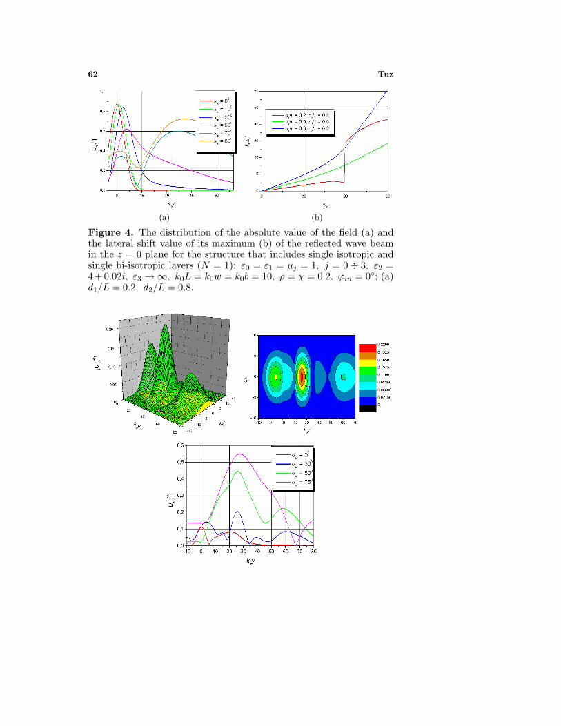
Figure 4. The distribution of the absolute value of the field (a) andthe lateral shift value of its maximum (b) of the reflected wave beamin the z = 0 plane for the structure that includes single isotropic andsingle bi-isotropic layers (N = 1): ε0 = ε1 = µj = 1, j = 0 ÷ 3, ε2 =4+0.02i, ε3 → ∞, k0L = k0w = k0b = 10, ρ = χ = 0.2, ϕin = 0◦; (a)d1/L = 0.2, d2/L = 0.8.

Progress In Electromagnetics Research B, Vol. 7, 2008 63

64 Tuz
Figure 5. The distribution of the absolute value of the field |Uref | ofthe reflected wave beam in the z = 0 plane for the sequence of N = 5isotropic and bi-isotropic layers (the passing regime): ε0 = ε1 = µj =1, j = 0÷3, ε2 = 4, k0L = k0w = k0b = 10, d1/L = d2/L = 0.5, ρ =χ = 0.2.
If the structure includes the single basic element (N = 1) and isbacked by a metal ground plane, the reflection coefficient magnitudeof the co-polar wave |Rss| is weakly depend from the falling angle andis nearly per unit (Fig. 2a). When ϕin = 0, for the two-dimensionalbeam, during [1], the field components U ee
ref and Uhhref of the reflected
beam have the next view
U ssref (y, z) = exp {iΦss(κ0)}Rss(κ0)Vs
×∫ ∞
−∞U(κin) exp
{i[(κin − κ0)(y + ∆s
y) − iγz]}dκin,
(17)
where κ0 = k sinαin and Φss(κ0) is the phase of the reflection

Progress In Electromagnetics Research B, Vol. 7, 2008 65

66 Tuz
Figure 6. The distribution of the absolute value of the field |Uref |of the reflected wave beam in the z = 0 plane for the sequenceof N = 5 isotropic and bi-isotropic layers (the reflecting regime):ε0 = ε1 = µj = 1, j = 0 ÷ 3, ε2 = 4 + 0.02j, ε3 → ∞, k0L =k0w = k0b = 10, d1/L = d2/L = 0.5, ρ = χ = 0.2, αin = 30◦.

Progress In Electromagnetics Research B, Vol. 7, 2008 67
coefficient of the partial wave which falls under an angle αin. Thescattered beam shift along the illuminated boundary of the structureis defined from the condition ∆s
y = −(∂Φss/∂κ)κ=κ0 . It is sizeablewhen the phase of the partial plane wave scattering coefficient rapidlychanges with the angle. When the angle of the falling beam is nearly tothe quasi-Brewster angle or greater then it, the splitting of the reflectedbeam into two beams with different intensity value appears (Fig. 4).
When N > 1, the shift of the reflected beam along the illuminatedboundary of the structure increases due to multiple reflections of wavesfrom the boundaries of the layers (Figs. 5, 6). The beam splitting isobserved on the angles that lie nearly of the totally transmission anglesof the partial plane wave.
Increasing the chiral parameter ρ raises the structure reflection,changes the ellipticity and slightly raises the lateral shift of thereflected beam. The maximum of the intensity for the cross-polarwave corresponds to the minimum of the intensity for the co-polarwave. There are the areas of the practically totally transformation ofthe co-polar wave into the cross-polar wave. To the presence of themedia nonreciprocity (χ �= 0) is |U eh| �= |Uhe| and the sizeable cross-polar component in the scattered field appears even for case of thestraight incident wave beam (αin = 0◦).
We would like to emphasize an important peculiarity of the systemunder study regarding its application in the design of high-precisionmatched loads and layered absorbing coatings (Fig. 6) [24, 25, 29]. Thispeculiarity consists in reducing the co-polar reflection due to wavetransformation into the cross-polar reflection.
5. CONCLUSION
In this paper, we have investigated the tree-dimensional Gaussian beamscattering for the DBR-like bounded periodic sequence of pairs of bi-isotropic and magnetodielectric layers. The lateral shift, ellipticitychange, beam splitting is studied. The revealed effects allows us torecommend the application of the studied structure in the design ofcascaded high-Q and stop-band frequency filters, wave transformers,angular discriminators, absorbers, etc.
APPENDIX A.
With zm = mL, zm1 = mL+d1, notations, the field components in them-th period of the structure zm ≤ z ≤ zm1 and zm1 ≤ z ≤ (m + 1)L

68 Tuz
are written as follows (the factor exp[−i(ωt− kyy)] is omitted):
{Ee
x1
Ehy1
}= ±
1/√Y e
1
i/√Y h
1
×({Ae
m
Ahm
}exp[ikz1(z − zm)] ±
{Be
m
Bhm
}exp[−ikz1(z − zm)]
),
{He
y1
Hhx1
}=
√Y e
1
i√Y h
1
×({Ae
m
Ahm
}exp[ikz1(z − zm)] ∓
{Be
m
Bhm
}exp[−ikz1(z − zm)]
),
{Ex2
Ey2
}=±
1/2√Y e+
2
i/2√Y h+
2
(A+
m exp[iγ+z (z−zm1)]±B+
m exp[−iγ+z (z−zm1)]
)
+
1/2√Y e−
1
i/2√Y h−
1
(A−
m exp[iγ−z (z−zm1)]±B−m exp[−iγ−z (z−zm1)]
),
{Hy2
Hx2
}=
√Y e+
2 /2
i√Y h+
2 /2
(A+
m exp[iγ+z (z−zm1)]∓B+
m exp[−iγ+z (z−zm1)]
)
±
√Y e−
2 /2
i√Y h−
2 /2
(A−
m exp[iγ−z (z−zm1)]∓B−m exp[−iγ−z (z−zm1)]
),
The field components at the structure output are
{Ee
x3
Ehy3
}= ±
(1/
√Y e
3
)Ae
N+1(i/
√Y h
3
)Ah
N+1
exp[ikz3(z −NL)],
{He
y3
Hhx3
}= ±
√Y e
3 AeN+1
i√Y h
3 AhN+1
exp[ikz3(z −NL)].
Here kzj = kj cosαj , kyj = kj sinαj , kj = k0nj , nj = √εjµj , Y
ej =
η−1j cosαj , Y
hj = (ηj cosαj)−1, ηj =
√µj/εj , sinαj = sinα0n0/nj
and j �= 2.

Progress In Electromagnetics Research B, Vol. 7, 2008 69
APPENDIX B.
The elements of the transfer matrix T = T 1T 2 are:
T ee1± =
1
2√Y e
1 Ye±2
(Y e
1 + Y e±2 Y e
1 − Y e±2
Y e1 − Y e±
2 Y e1 + Y e±
2
)E1,
T eh1± = ± 1
2√Y h
1 Yh±2
(Y h±
2 + Y h1 Y h±
2 − Y h1
Y h±2 − Y h
1 Y h±2 + Y h
1
)E1,
T hh1± =
1
2√Y h
1 Yh±2
(Y h±
2 + Y h1 Y h±
2 − Y h1
Y h±2 − Y h
1 Y h±2 + Y h
1
)E1,
T he1± = ∓ 1
2√Y e
1 Ye±2
(Y e
1 + Y e±2 Y e
1 − Y e±2
Y e1 − Y e±
2 Y e1 + Y e±
2
)E1,
T ee2± =
1
4Y e∓2
√Y e
1 Ye±2
×
(Y e∓
2 + Y e1
) (Y e∓
2 + Y e±2
)−
(Y e∓
2 − Y e1
) (Y e∓
2 − Y e±2
)(Y e∓
2 − Y e1
) (Y e∓
2 + Y e±2
)−
(Y e∓
2 + Y e1
) (Y e∓
2 − Y e±2
)(Y e∓
2 − Y e1
) (Y e∓
2 + Y e±2
)−
(Y e∓
2 + Y e1
) (Y e∓
2 − Y e±2
)(Y e∓
2 + Y e1
) (Y e∓
2 + Y e±2
)−
(Y e∓
2 − Y e1
) (Y e∓
2 − Y e±2
) E±
2 ,
T eh2± = ∓ 1
4Y h∓2
√Y h
1 Yh±2
×
(Y h∓
2 + Y h1
) (Y h∓
2 + Y h±2
)−
(Y h∓
2 − Y h1
) (Y h∓
2 − Y h±2
)(Y h∓
2 + Y h1
) (Y h∓
2 − Y h±2
)−
(Y h∓
2 − Y h1
) (Y h∓
2 + Y h±2
)(Y h∓
2 + Y h1
) (Y h∓
2 − Y h±2
)−
(Y h∓
2 − Y h1
) (Y h∓
2 + Y h±2
)(Y h∓
2 + Y h1
) (Y h∓
2 + Y h±2
)−
(Y h∓
2 − Y h1
) (Y h∓
2 − Y h±2
) E±
2 ,
T hh2± =
1
4Y h∓2
√Y h
1 Yh±2
×
(Y h∓
2 + Y h1
) (Y h∓
2 + Y h±2
)−
(Y h∓
2 − Y h1
) (Y h∓
2 − Y h±2
)(Y h∓
2 + Y h1
) (Y h∓
2 − Y h±2
)−
(Y h∓
2 − Y h1
) (Y h∓
2 + Y h±2
)

70 Tuz(Y h∓
2 +Y h1
) (Y h∓
2 −Y h±2
)−
(Y h∓
2 − Y h1
)(Y h∓
2 + Y h±2
)(Y h∓
2 +Y h1
) (Y h∓
2 +Y h±2
)−
(Y h∓
2 − Y h1
)(Y h∓
2 − Y h±2
)E±
2 ,
T he2± = ∓ 1
4Y e∓2
√Y e
1 Ye±2
×
(Y e∓
2 + Y e1
) (Y e∓
2 + Y e±2
)−
(Y e∓
2 − Y e1
) (Y e∓
2 − Y e±2
)(Y e∓
2 − Y e1
) (Y e∓
2 + Y e±2
)−
(Y e∓
2 + Y e1
) (Y e∓
2 − Y e±2
)(Y e∓
2 − Y e1
) (Y e∓
2 + Y e±2
)−
(Y e∓
2 + Y e1
) (Y e∓
2 − Y e±2
)(Y e∓
2 + Y e1
) (Y e∓
2 + Y e±2
)−
(Y e∓
2 − Y e1
) (Y e∓
2 − Y e±2
) E±
2 ,
where
E1 = Diag(exp(−ikz1d1) exp(ikz1d1)),E±
2 = Diag(exp(−iγ±z d2) exp(iγ±z d2)).
REFERENCES
1. Brekhovskikh, L M., Waves in Layered Media, Academic Press,New York, 1960.
2. Goncharenko, A. M., Gaussian Beams of Light, Minsk, Nauka &Tekhnika, 1977 (in Russian).
3. Horowitz, B. R. and T. Tamir, “Lateral displacement of a lightbeam at a dielectric interface,” J. Opt. Soc. Am., Vol. 61, 584–594,1971.
4. Tretyakova, S. S., O. A. Tretyakov, V. P. Shestopalov, “Wavebeam diffraction on plane periodical structures,” Radiotekhnika &Electronica, Vol. 17, 1366–1373, July 1972 (in Russian).
5. Shin, S. Y. and L. B. Felsen, “Lateral shift of totally reflectedGaussian beams,” Radio Sci., Vol. 12, 551–564, July 1977.
6. Godin, O. A., “Diffraction theory of lateral shift of bounded wavebeams during reflection,” Zh. Tekh. Fiz., Part 1, Vol. 54, 2094–2104, 1984; Part 2, Vol. 55, 17–25, 1985 (in Russian).
7. Riesz, R. P. and R. Simon, “Reflection of Gaussian beam from adielectric slab,” J. Opt. Soc. Am. A, Vol. 2, 1809–1817, 1985.
8. Maciel, J. and L. Felsen, “Gaussian beam analysis of propagationfrom an extended plane aperture distribution through dielectriclayers,” IEEE Trans. Antennas Propagat., Vol. AP-38, 1607–1624,October 1990.

Progress In Electromagnetics Research B, Vol. 7, 2008 71
9. Shulga, S. N., “Two-dimensional wave beam scattering onan anisotropic half-space with anisotropic inclusion,” Optics &Spectroscopy, Vol. 87, 503–509, March 1999 (in Russian).
10. Tuz, V. R., “Gaussian beam scattering from a bounded periodicsequence of perfectly conducting bars,” Radiotekhnika, Vol. 135,62–67, 2003 (in Russian).
11. Bass, F. and L. Resnick, “Wave beam propagation in layeredmedia,” Journal of Electromagnetic Waves and Applications,Vol. 17, No. 3, 479–480, 2003.
12. Lomakin, V. and E. Michielssen, “Beam transmission troughperiodic subwavelength hole structures,” IEEE Trans. AntennasPropagat., Vol. AP-55, 1564–1581, June 2007.
13. Hoppe, D. J. and Y. Rahmat-Samii, “Gaussian beam reflection ata dielectric-chiral interface,” Journal of Electromagnetic Wavesand Applications, Vol. 6, 603–624, 1992.
14. Maksimenko, S. A., G. Ya. Slepyan, and A. Lakhtakia, “Gaussianpulse propagation in a linear, lossy, chiral medium,” J. Opt. Soc.Am. A, Vol. 14, 894–900, April 1997.
15. Maksimenko, S. A. and G. Ya. Slepyan, “Pulse propagation inlinear and nonlinear chiral media,” Int. Conf. and Workshop onElectromag. Complex Media, BIANISOTROPICS’97, Glasgow,Scotland, June 5–7, 1997.
16. Mahmoud, S. F. and S. Tariq, “Gaussian beam splitting by achiral prism,” Journal of Electromagnetic Waves and Applications,Vol. 2, 73–83, January 1998.
17. Malyuskin, A. V., D. N. Goryushko, S. N. Shulga, A. A. Shmat’ko,“Scattering of a wave beam by inhomogeneous anisotropic chirallayer,” Int. Conf. on Math. Methods in EM Theory (MMET 2002),566–568, Kyiv, Ukraine, September 10–13, 2002.
18. Kopp, V. I., Z.-Q. Zhang, and A. Z. Genack, “Lasing in chiralphotonic structures,” Prog. Quantum Electron., Vol. 27, 369–416,June 2003.
19. Ghosh, A. and P. Fischer, “Chiral molecules split light: reflectionand refraction in a chiral liquid,” Phys. Rev. Lett., Vol. 97, 2006.
20. Luk, K. M. and A. L. Cullen, “Three-dimensional Gaussian beamreflection from short-circuited isotropic ferrite slab,” IEEE Trans.Antennas Propagat., Vol. 41, 962–966, July 1993.
21. Born, M. and E. Wolf, Principle of Optics, Oxford, PergamonPress, 1968.
22. Zhang, Y. J., A. Bauer, and E. P. Li, “T-Matrix analysis ofmultiple scattering from parallel semi-circular channels filled with

72 Tuz
ciral media in a conducting plane,” Progress In ElectromagneticsResearch, PIER 53, 299–318, 2005.
23. Kim, G. and E. Garmire, “Comparison between the matrixmethod and the coupled-wave method in the analysis of Braggreflector structures,” J. Opt. Soc. Am. A, Vol. 9, 132–137, 1992.
24. Kazanskiy, V. B. and V.V. Podlozny, “Quasiperiodic layeredstructure with resistive film,” Electromagnetics, Vol. 17, 131–145,March–April 1997.
25. Kazanskiy, V. B., V. R. Tuz, and V. V. Khardikov, “Quasiperiodicmetal-dielectric structure as a multifunctional control system,”Radioelectronics and Communications Systems, Vol. 45, 38–46,July 2002.
26. Lindell, I. V., A. H. Sihvola, S. A. Tretyakov, and A. J. Viitanen,Electromagnetic Waves in Chiral and Bi-Isotropic Media, ArtechHouse, Boston, London, 1994.
27. Lakhtakia, A., V. K. Varadan, and V. V. Varadan, Time-Harmonic Electromagnetic Fields in Chiral Media, Lecture Notesin Physics, Springer-Verlag, 1989.
28. Kazanskiy, V. B. and V. R. Tuz, “Scattering fields of Chirallayers periodical sequence,” Int. Conference on Antenna Theoryand Tech., 177–180, Sevastopol, Ukraine, September 17–21, 2007.
29. Norgen, M., “On the possibility of reflectionless coating ofa homogeneous bianisotropic layer on a perfect conductor,”Electromagnetics, Vol. 17, 295–307, April 1997.
30. Varadan, V. K., Y. Ma, and V. V. Varadan, “Microwave propertiesof chiral composites,” Progress In Electromagnetics Research,PIER 6, 327–344, 1992.
31. Mariotte, F., P. Pelet, and N. Engeta, “A rewiew of recent studyof guided waves in chiral media,” Progress In ElectromagneticsResearch, PIER 9, 311–350, 1994.
32. Komar, G. I. and A. Y. Poyedinchuk, “Mode transfigurationsin chirowaveguides,” Journal of Electromagnetic Waves andApplications, Vol. 17, No. 7, 1043–1044, 2003.
33. Zheng, L. G. and W. X. Zhang, “Analysis of bi-anisotropicPBG structure using plane wave expansion method,” Journal ofElectromagnetic Waves and Applications, Vol. 17, No. 10, 1419–1420, 2003.
34. Hussain, A. and Q. A. Naqvi, “Fractional curl operator in chiralmedium and fractional non-symmetric transmission line,” ProgressIn Electromagnetics Research, PIER 59, 199–213, 2006.
35. Panin, S. B., P. D. Smith, and A. Y. Poyedinchuk, “Elliptical

Progress In Electromagnetics Research B, Vol. 7, 2008 73
to linear polarization transformation by a grating on a chiralmedium,” Journal of Electromagnetic Waves and Applications,Vol. 21, No. 13, 1885–1899, 2007.
36. Kuzu, L., V. Demir, A. Z. Elsherbeni, and E. Arvas,“Electromagnetic scattering from arbitrarily shaped chiral objectsusing the finite difference frequency domain method,” Progress InElectromagnetics Research, PIER 67, 1–24, 2007.
37. Hussain, A., M. Faryad, and Q. A. Naqvi, “Fractionalcurl operator and fractional chiro-waveguide,” Journal ofElectromagnetic Waves and Applications, Vol. 21, No. 8, 1119–1129, 2007.