three dimensional body scanning systems … dimensional body scanning systems with potential for use...
TRANSCRIPT

THREE DIMENSIONAL BODY SCANNING SYSTEMS WITH
POTENTIAL FOR USE IN THE APPAREL INDUSTRY
By
SU-JEONG HWANG, B.S., M.S.
A paper (A-1) submitted to the Graduate Faculty of
North Carolina State University
in partial fulfillment of the requirement for the Degree of
Doctor of Philosophy
TEXTILE TECHNOLOGY AND MANAGEMENT
Raleigh
2001
APPROVED BY:
ABSTRACT
THREE DIMENSIONAL BODY SCANNING SYSTEMS WITH POTENTIAL
FOR USE IN THE APPAREL INDUSTRY
Su-Jeong Hwang, January, 2001
The technology of three dimensional human body scanning systems is used in
various applications, such as movies’ special effects, anthropology, hospitals, militaries,
and made to measure garments in apparel. The purpose of this study was to understand
the principles of the scanning system and to determine currently available 3D body
scanning systems that have feasibility for use in the apparel by an analysis and
comparison of the systems.
Nineteen companies have been investigated. Cyberware, Hamano, Vitronic,
TecMath, TC2, Telmat, Wicks and Wilson, and Hamamatsu are currently appropriate for
use in the apparel industry for measurement of human body size.
The principle of the 3D body scanning systems is based on optical triangulation
by non-contact methods using either laser or light projection systems. The body scanner
scans the surface of a three-dimensional object, projecting either laser or light, and using
vision devices to capture the shape of the object. The data from the scan is extracted by a
software program.
Cyberware, Vitronic, Hamano, TecMath, and Vitronic use a laser and TC2, Wicks
and Wilson, Telmat, and Hamamatsu use a light source and various techniques for
capture. TC2 and Wicks and Wilson use similar methods by using white light sources,
however Hamamatsu uses a near infrared light LED with PSD method.

By comparison of the scanning systems, I found that light projection types of
scanners, such as TC2 and Triform, are usually faster in scanning time but slower in
extraction of the measurement data than the Laser types. The Hamamatsu BL scanner,
using near infrared LED, and SYMCAD are faster in extraction time than the body
scanning systems which use a moiré technique method.
Three dimensional body scanning systems have advantages of accuracy and high
speed in the measuring process compared to the traditional tape method. It will be a
beneficial technology for the apparel industry in the development of mass customization.
Rapid 3D body scanning and data analysis can accurately specify uniform sizes to reduce
time, errors, and cost. However, problems have been found on missing data due to the
shading effects and inconsistency in body positioning.
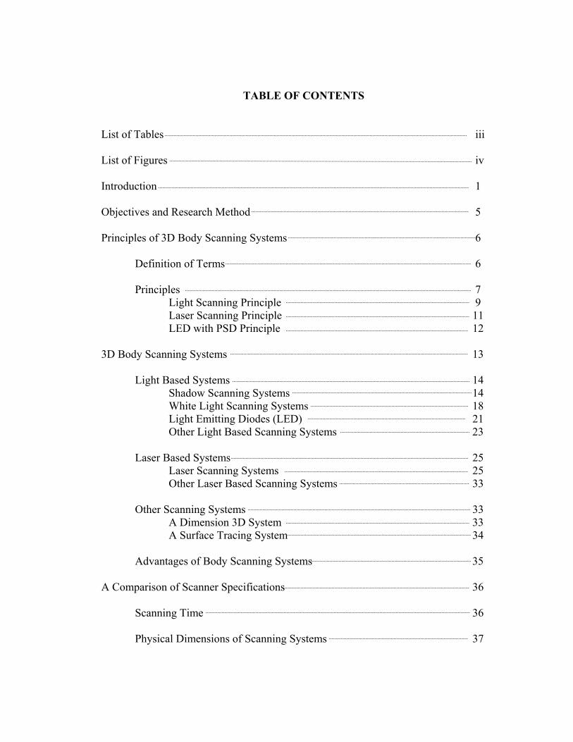
TABLE OF CONTENTS
List of Tables iii List of Figures iv Introduction 1 Objectives and Research Method 5 Principles of 3D Body Scanning Systems 6
Definition of Terms 6
Principles 7 Light Scanning Principle 9 Laser Scanning Principle 11 LED with PSD Principle 12 3D Body Scanning Systems 13
Light Based Systems 14
Shadow Scanning Systems 14 White Light Scanning Systems 18 Light Emitting Diodes (LED) 21 Other Light Based Scanning Systems 23
Laser Based Systems 25
Laser Scanning Systems 25 Other Laser Based Scanning Systems 33
Other Scanning Systems 33
A Dimension 3D System 33 A Surface Tracing System 34
Advantages of Body Scanning Systems 35
A Comparison of Scanner Specifications 36
Scanning Time 36 Physical Dimensions of Scanning Systems 37

Vision Device 39 Operating Requirements 43
Conclusion and Suggestions 49 References 52

iiiList of Tables
Table I. 3D Scanning Systems by Type 14
Table II. Comparison of Scanning Time 36
Table III. Comparison by Booth Size, Volume, and Data Size 38
Table IV. Light Source and Vision Devices 40
Table V. Comparison of the Computer Requirements 43
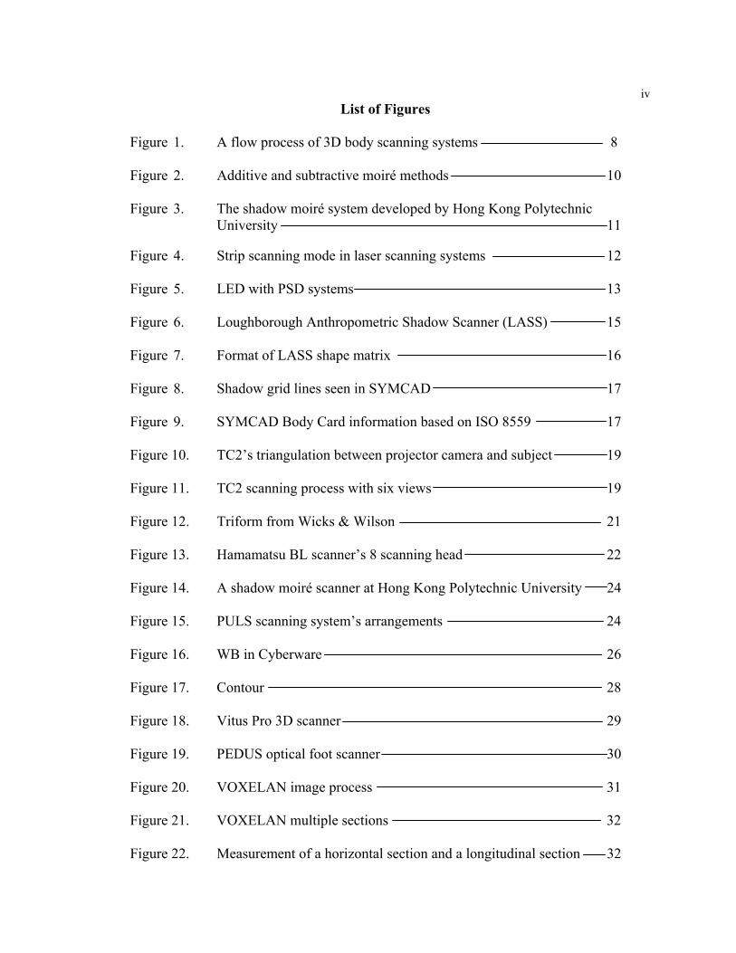
ivList of Figures
Figure 1. A flow process of 3D body scanning systems 8
Figure 2. Additive and subtractive moiré methods 10
Figure 3. The shadow moiré system developed by Hong Kong Polytechnic University 11
Figure 4. Strip scanning mode in laser scanning systems 12
Figure 5. LED with PSD systems 13
Figure 6. Loughborough Anthropometric Shadow Scanner (LASS) 15
Figure 7. Format of LASS shape matrix 16
Figure 8. Shadow grid lines seen in SYMCAD 17
Figure 9. SYMCAD Body Card information based on ISO 8559 17
Figure 10. TC2’s triangulation between projector camera and subject 19
Figure 11. TC2 scanning process with six views 19
Figure 12. Triform from Wicks & Wilson 21
Figure 13. Hamamatsu BL scanner’s 8 scanning head 22
Figure 14. A shadow moiré scanner at Hong Kong Polytechnic University 24
Figure 15. PULS scanning system’s arrangements 24
Figure 16. WB in Cyberware 26
Figure 17. Contour 28
Figure 18. Vitus Pro 3D scanner 29
Figure 19. PEDUS optical foot scanner 30
Figure 20. VOXELAN image process 31
Figure 21. VOXELAN multiple sections 32
Figure 22. Measurement of a horizontal section and a longitudinal section 32

1
THREE DIMENSIONAL BODY SCANNING SYSTEMS WITH POTENTIAL
FOR USE IN THE APPAREL INDUSTRY
Introduction
A very important first step in determining correct sizing or creating customized
garments is obtaining accurate measurements of the specific human body. Historically,
tailors and fashion designers have used measuring tapes to obtain the physical
measurements of the bodies they created for. This method has been time consuming,
invasive, and often inaccurate, based on who took the measurements and how they took
them. Until just recently, only tailors and couture houses actually still used real body
measurements to create or alter the clothing they produced. Mass production strategies of
the past 50 years encouraged the move from “garments made to fit” to “garments made to
size”. Unfortunately, the sizing systems that have developed through the years are
neither standardized nor related to the average human’s body measurements.
Most people have a problem with fit in the clothing that is currently available in
the marketplace, in one way or another. Many have learned to make do with the
garments available for purchase by avoiding certain features that always cause a fit
problem with their different than average figures or by obtaining the service of tailors or
alterations specialists. Others have simply learned to do without. Regardless, there is a
very large population of dissatisfied consumers today. This underlying dissatisfaction
provided impetus to the birth of the paradigm of mass customization.
In the apparel industry, the ability to customize garments for fit is directly tied to
the availability of a comprehensive, accurate set of measurements for each interested

2
consumer. Regardless of how one might perceive “fit” to be good or bad, it is impossible
to even get close to meeting the consumer’s perceptions of good fit without a set of
accurate measurements to begin with. To obtain accurate physical measurements, a basic
knowledge and set of skills are required that are not often found in the average
salesperson at a retail clothing outlet. In addition, most consumers are unwilling to take
time to be measured or subject themselves to the intrusion. A 1988 anthropometric
survey of US Army personnel required 4 hours to physically landmark, measure, and
record the data of one subject (Paquette, 1996). This demonstrates how time consuming
the traditional measurement process is.
The development of three dimensional body-scanning technologies may have
significant potential for use in the apparel industry, for a number of reasons. First, this
technology has the potential of obtaining an unlimited number of linear and non-linear
measurements of human bodies (in addition to other objects) in a matter of seconds.
Because an image of the body is captured during the scanning process, the location and
description of the measurements can be altered as needed in mere seconds, as well.
Second, the measurements obtained using this technology have the potential of being
more precise and reproducible than measurements obtained through the physical
measurement process. Third, with the availability of an infinite number of linear and
non-linear measurements the possibility exists for garments to be created to mold to the
three dimensional shapes of unique human bodies. Finally, the scanning technology
allows measurements to be obtained in a digital format that could integrate automatically
into apparel CAD systems without the human intervention that takes additional time and

3
can introduce error. Ultimately, it may enable the industry to produce mass customized
garments.
According to a study using laser holography in the measurement of human bodies
(Shentu, 1995), the laser scanning system was fast, easy, and accurate, and also had the
ability to record data on the computer. This study demonstrated potential in other
applications, such as size points recognition, sampling methods, high speed measurement
methods, and oriented size application for design, draping, and garment design.
The technology of three dimensional (3D) body scanning has been used most
extensively by the military to rapidly and accurately scan, extract measurements, and
automatically select sizes for issuing garments to military recruits. Plans are for the
scanning process to be integrated into the recruit issue line so that it will take less than
one minute to scan and size each recruit.
In 1998, the Civilian American and European Surface Anthropometry Resource
program (CAESAR) at Wright-Patterson Air Force Base initiated the largest scale
anthropometric survey performed in over 30 years. It is the first international survey of
its kind to utilize body-scanning technology. The Cyberware WB4 whole body scanner
was used in this study (CAESAR, 1999). The collected data will be used by multiple
industries, including the military, automotive, and apparel.
Textile Clothing Technology Corporation ([TC]²) of Cary, North Carolina, a non-
profit organization funded in part by the government, has focused a significant amount of
research and development time and effort on 3D body scanning and measurement
extraction. This organization is committed to aiding in the development of technologies
that will support the American apparel industry. It is this commitment that encouraged
4
research in body scanning technologies that could support the developing paradigm of
mass customization ([TC]², 2000).
Three-dimensional body scanning technologies are already being used in the
apparel industry. Levi-Strauss has placed a scanning system in their San Francisco,
California store and has experimented with the production of made-to-measure jeans.
Brooks Brothers has used measurements extracted from scanned bodies to produce their
own customized shirts. They measure customers within a few seconds and then send the
measurement data to their factory to produce the garments in a few days. Integrating the
scanning process and revising production systems can help reduce inventory levels and
cut order lead-time.
In the apparel industry, designing, spreading, cutting, and pressing have been
automated by use of computer systems. According to Mittelhauser (1997), many large
apparel producers have implemented these technologies. Computer-aided-design (CAD)
and computer-aided-manufacturing (CAM) systems have significantly increased
productivity and efficiency within the industry. Integration of 3D body scanning
technologies with existing CAD/CAM systems is essential.
Three-dimensional scanning technologies may support the development of 3D
virtual shopping where consumers can see themselves in selected clothing, via the web.
Virtual displays at point of sale and catalogue shopping may also be perpetuated by this
technology. In addition, business-to-business (B2B) applications may be enhanced by
enabling more accurate garment visualization and inspection. The company
realityBUY.com has joined forces with ASP, idealpath Inc. to develop such a virtual
showroom (Business Wire, 2000).

5
The purpose of this study was to uncover all of the 3D body scanning systems
currently available and to determine the underlying principles that allow these systems to
work. Specifications of each system were compared in order to provide some direction
for further research into the integration of these systems with current apparel CAD
technology.
Objectives and Research Method
The objectives of this study were to a) search all currently available 3D body
scanning systems, worldwide; b) understand the underlying principles of each of the 3D
body scanning systems; c) assess the ability to integrate these systems with other
technologies used in the apparel industry by comparison of the scanning time, volume of
the scanner booth, vision device, and computer system; d) gather specific information on
the required system environments, such as the computer operating system, the software,
the hardware, and data formats; and e) suggest further study of system integration in the
apparel industry. Nineteen companies that had developed body-scanning systems were
investigated between December, 1999 and December, 2000. The companies were
Cyberware, [TC]², Telmat, Wicks and Wilson, Hamamatsu, Vitronic, TecMath, 3D
Scanners, Immersion, Hamano, Puls Scanning system, LASS (Loughborough
Anthropometric Shadow Scanner), Cognitens, Carl Zeiss, Faro Technologies, Science
Accessory, Turing C3D, CAD Modeling, and Polhemus. A survey was mailed to each of
the companies, twice, to gather information related to system specifications and
capabilities. Six of the companies responded to the survey by email, mail, and/or fax.
6
Information on the remaining companies was obtained in person, from their web sites, or
through previous related articles and papers.
Principles of 3D Body Scanning Systems
Definition of Terms
Body scanning systems have been developing in different fields such as optical
engineering, computer science, and anthropometry. They use technical terms and
abbreviated words that are already commonly used in specific areas or projects.
However, many of the terms related to3D body scanning systems are not yet familiar to
the apparel industry. Therefore, the following terms are provided to help understand the
3D body scanning systems.
3DM: Software program developed by Clemson Apparel Research. 3DM reads
image files, is written in C++, uses open GL and W-Windows libraries, and runs on both
an SGI workstation running Unix and on a PC running Windows NT (Pargas, 1998).
3D ScanWare: The unique interface between the hardware components developed
by Dimension 3D-System.
ARN: Apparel Research Network.
CAR: Clemson Apparel Research
CCD: Charge-coupled device. This is a head part of the vision devices in a
scanner.
HUMAG: Human Measurement, Anthropometry and Growth Research Group, is
the body scan research component at Loughborough University.
7
LASS: Loughborough Anthropometric Shadow Scanner. Loughborough
University in U.K. has been developed the shadow scanning system.
LED: Light Emit Diodes.
PMP: Phase Measuring Profilometry. It employs a phase-stepping technique
using moiré-based light-projection system for commercialized for the custom apparel
design and manufacturing systems. It improves overall image resolution (Paquette,
1996). It has been developed by [TC]² in Cary, North Carolina.
PSD: Position-Sensitive Detector.
SGI: Silicon Graphics Inc. is a major pioneer in VRML, which is useful in
developing web sites.
Principles
An early model of a 3D body scanning system was found that Japanese
researchers had developed consisting of a mechanical sliding gauge to trace the
horizontal and vertical curves of a human body. The early non-contact measuring device,
a silhouetter, produced a 2D photo of a body contour. It consisted of a booth with large
grid wall, a series of florescent light tubes, and an instant camera.
In 1984, Wacoal developed a computerized silhouette analyzer that could
electronically process data on the contours of an object (Yu, 1999). It was a very similar
idea to 3D body scanning systems in terms of using a non-contact method with light
sources.
Current three-dimensional body scanners capture the outside surface of the human
body by using optical techniques, in combination with light sensitive devices, without
physical contact with the body, in the majority of cases. Body scanning systems consist

8
of one or more light sources, one or more vision or capturing devices, software, a
computer system, and a monitor screen in order to visualize the data capture process.
The primary types of body scanning systems are laser and light. Surface tracing systems
also exist. However, these are not currently used for capturing the shape of human
bodies. Both white light and laser scanning systems follow four main process steps (see
Figure 1).
First, an object is illuminated and scanned by mechanical motion of the light
sources, either white light or laser. Second, CCD cameras detect the reflected patterns
from the object. Third, the displacement of the structured light pattern is used to
calculate the distance from the subject to the CCD camera. Finally, software inverts the
distance data to produce a three-dimensional representation. According to Kaufmann
(1997), in the final step of the software inversion, a certain amount of redundancy is
needed in the measurements to overcome shadowing of arms and ears. For the apparel
Figure 1. A flow process of 3D body scanning systems
(Operating systems) (4) Software inversion data
(3) Calculation
(Vision Devices) (1) Light illumination (2) Camera detection
Printer
Screen
Computer
Memory frame
Floppy disk
Customized card CAD system
Object
CameraLight Projector
9
industry, measurement data from the 3D body scanning systems could be stored in a
customized card and integrated to CAD systems used by the apparel industry.
Most 3D body scanning systems currently available differ slightly by the source
of light or their methods. They can be explained as three different principles, which are
light based scanning systems, laser scanning systems, and LED with PSD systems.
Light Scanning Principle
Most white light 3D body scanning systems with grid lines have been developed
from the shadow moiré technique. Hong Kong Polytechnic University, Triform from
Wicks & Wilson, and [TC]² are examples of white light scanning systems, which have
developed their own body scanners with this technique. The white light sources are
usually referred to as Halogen lamps.
In the moiré technique, a grid plane, camera, white light source, and operating
system are used. The use of grid lines is a main difference from other scanning
principles. While a human body is being scanned, we can usually recognize the
horizontal grid lines on the object.
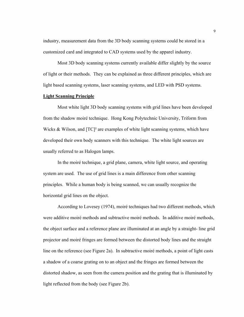
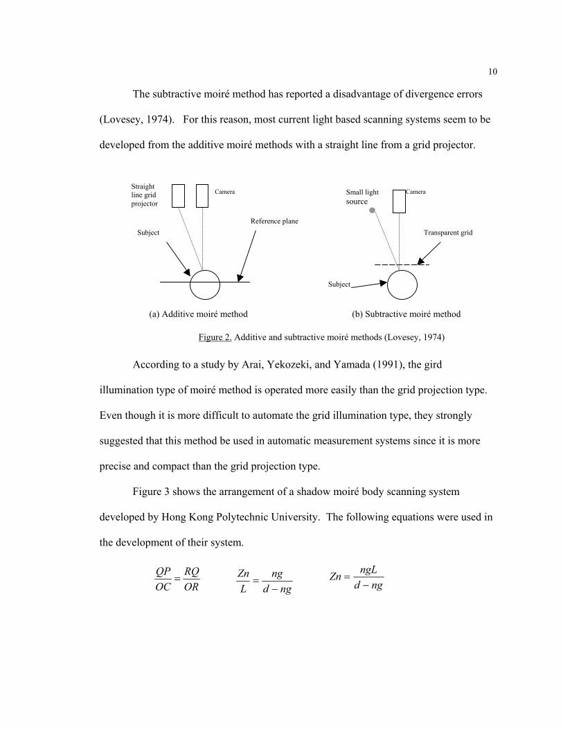
According to Lovesey (1974), moiré techniques had two different methods, which
were additive moiré methods and subtractive moiré methods. In additive moiré methods,
the object surface and a reference plane are illuminated at an angle by a straight- line grid
projector and moiré fringes are formed between the distorted body lines and the straight
line on the reference (see Figure 2a). In subtractive moiré methods, a point of light casts
a shadow of a coarse grating on to an object and the fringes are formed between the
distorted shadow, as seen from the camera position and the grating that is illuminated by
light reflected from the body (see Figure 2b).
10
The subtractive moiré method has reported a disadvantage of divergence errors
(Lovesey, 1974). For this reason, most current light based scanning systems seem to be
developed from the additive moiré methods with a straight line from a grid projector.
According to a study by Arai, Yekozeki, and Yamada (1991), the gird
illumination type of moiré method is operated more easily than the grid projection type.
Even though it is more difficult to automate the grid illumination type, they strongly
suggested that this method be used in automatic measurement systems since it is more
precise and compact than the grid projection type.
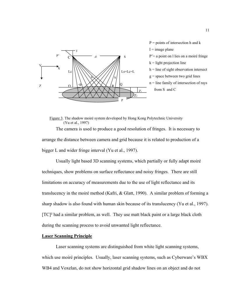
Figure 3 shows the arrangement of a shadow moiré body scanning system
developed by Hong Kong Polytechnic University. The following equations were used in
the development of their system.
ngd
ngL
Zn−
=ORRQ
OCQP
= ngdngLZn−
=
Figure 2. Additive and subtractive moiré methods (Lovesey, 1974)
Subject
Camera
Reference plane
Straight line grid projector
(a) Additive moiré method (b) Subtractive moiré method
Subject
Small lightsource
Camera
Transparent grid
11
The camera is used to produce a good resolution of fringes. It is necessary to
arrange the distance between camera and grid because it is related to production of a
bigger L and wider fringe interval (Yu et al., 1997).
Usually light based 3D scanning systems, which partially or fully adapt moiré
techniques, show problems on surface reflectance and noisy fringes. There are still
limitations on accuracy of measurements due to the use of light reflectance and its
translucency in the moiré method (Kafri, & Glatt, 1990). A similar problem of forming a
sharp shadow is also found with human skin because of its translucency (Yu et al., 1997).
[TC]² had a similar problem, as well. They use matt black paint or a large black cloth
during the scanning process to avoid unwanted light reflectance.
Laser Scanning Principle
Laser scanning systems are distinguished from white light scanning systems,
which use moiré principles. Usually, laser scanning systems, such as Cyberware’s WBX
WB4 and Voxelan, do not show horizontal grid shadow lines on an object and do not
C
Q
h
XY
I
Z2 Z1
k
R
Ls=Lc=L Lc
O -g-
SP’
P
d
Z
P = points of intersection h and k
I = image plane
P’= a point on l lies on a moiré fringe
k = light projection line
h = line of sight observation intersect
g = space between two grid lines
n = line family of intersection of rays
from S and C
Figure 3. The shadow moiré system developed by Hong Kong Polytechnic University (Yu et al., 1997)
12
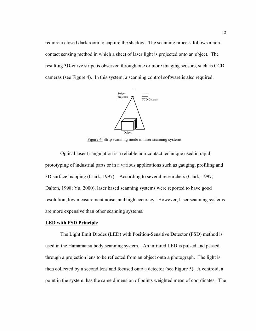
require a closed dark room to capture the shadow. The scanning process follows a non-
contact sensing method in which a sheet of laser light is projected onto an object. The
resulting 3D-curve stripe is observed through one or more imaging sensors, such as CCD
cameras (see Figure 4). In this system, a scanning control software is also required.
Optical laser triangulation is a reliable non-contact technique used in rapid
prototyping of industrial parts or in a various applications such as gauging, profiling and
3D surface mapping (Clark, 1997). According to several researchers (Clark, 1997;
Dalton, 1998; Yu, 2000), laser based scanning systems were reported to have good
resolution, low measurement noise, and high accuracy. However, laser scanning systems
are more expensive than other scanning systems.
LED with PSD Principle
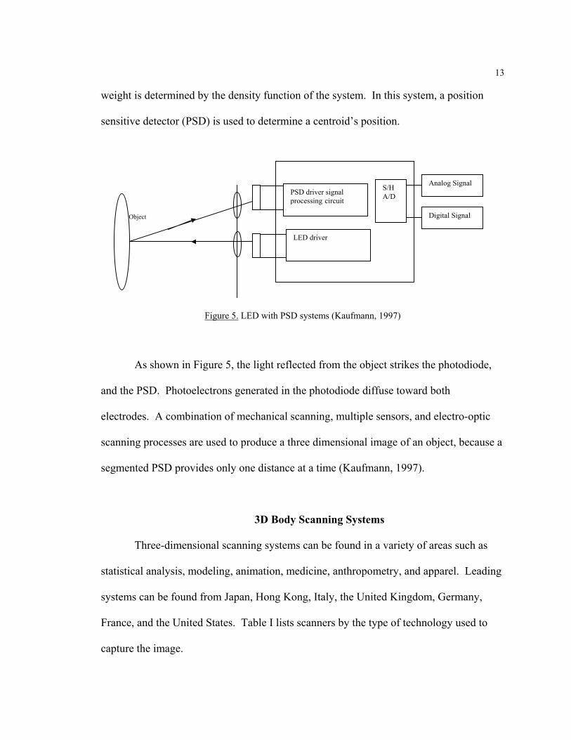
The Light Emit Diodes (LED) with Position-Sensitive Detector (PSD) method is
used in the Hamamatsu body scanning system. An infrared LED is pulsed and passed
through a projection lens to be reflected from an object onto a photograph. The light is
then collected by a second lens and focused onto a detector (see Figure 5). A centroid, a
point in the system, has the same dimension of points weighted mean of coordinates. The
CCD Camera
Stripe projector
Object
Figure 4. Strip scanning mode in laser scanning systems
13
weight is determined by the density function of the system. In this system, a position
sensitive detector (PSD) is used to determine a centroid’s position.
As shown in Figure 5, the light reflected from the object strikes the photodiode,
and the PSD. Photoelectrons generated in the photodiode diffuse toward both
electrodes. A combination of mechanical scanning, multiple sensors, and electro-optic
scanning processes are used to produce a three dimensional image of an object, because a
segmented PSD provides only one distance at a time (Kaufmann, 1997).
3D Body Scanning Systems
Three-dimensional scanning systems can be found in a variety of areas such as
statistical analysis, modeling, animation, medicine, anthropometry, and apparel. Leading
systems can be found from Japan, Hong Kong, Italy, the United Kingdom, Germany,
France, and the United States. Table I lists scanners by the type of technology used to
capture the image.
Object
PSD driver signal processing circuit
LED driver
S/H A/D
Analog Signal
Digital Signal
Figure 5. LED with PSD systems (Kaufmann, 1997)

14
Table I. 3D Scanning Systems by Type
Light Based Systems Laser Based Systems Other scanning Systems
Company Product Company Product Company Product
Hamamatsu BL Scanner Cyberware WBX, WB4 Immersion
Micro Scribe 3D
Loughborough University LASS TecMath
Ramsis, Contor, Vitus Pro, Vitus Smart
CAD modeling SCANFIT
[TC]²
2T4,3T6 Vitronic
VITUS/smart 3D body scanner, PEDUS 3D foot scanner, HighTechPerfection
Dimension
3D-System
Scan book, 3D Scan Station, 3D Scan Station Body
Wicks and Wilson Limited
TriForm BodyScan, TriForm3 (Torso Scan), TriForm2 (Head scan)
Hamano Voxelan
TELMAT
SYMCAD 3D Virtual model Polhemus FASTSCAN
Turing Turing C3D 3D Scanners
REPLICA, Model Maker, REVERSA, Re Mesh, RI Software, PROFA
Puls Scanning System GmbH Puls Scanning System
Hong Kong Polytechnic University
Shadow moiré body scanning system
CogniTens Optigo 100 system
Light Based Systems
Shadow Scanning Systems
LASS. One of the earliest 3D body scanning systems was a shadow scanning
method developed by Loughborough University in the U.K. The LASS shadow scanner
was used in the Human Measurement, Anthropometry and Growth Research Group
(HUMAG). Anthropometric surveys throughout Britain have been undertaken to describe
the body sizes and shapes of adults. The LASS, 3D automatic body measuring system
was aimed at the automation of clothing sizing and design and applications in
manufacturing industries and medicine (HUMAG, 2000).
15
The Loughborough Anthropometric Shadow Scanner (LASS) differs from other
conventional structured lighting approaches in that they rotate an object. However, the
principle of shadow scanners is similar to the most conventional structured lighting
systems in that the camera faces the scene illuminated by a halogen light source and the
camera captures images as an operator moves the light so that the shadow scans the entire
scene. This constitutes the input data to the 3D reconstruction system (Bouguet &
Perona, 2000).
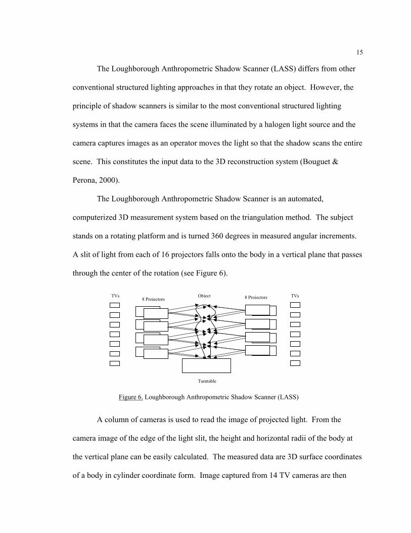
The Loughborough Anthropometric Shadow Scanner is an automated,
computerized 3D measurement system based on the triangulation method. The subject
stands on a rotating platform and is turned 360 degrees in measured angular increments.
A slit of light from each of 16 projectors falls onto the body in a vertical plane that passes
through the center of the rotation (see Figure 6).
A column of cameras is used to read the image of projected light. From the
camera image of the edge of the light slit, the height and horizontal radii of the body at
the vertical plane can be easily calculated. The measured data are 3D surface coordinates
of a body in cylinder coordinate form. Image captured from 14 TV cameras are then
TVs TVs 8 Projectors 8 Projectors
Turntable
Object
Figure 6. Loughborough Anthropometric Shadow Scanner (LASS)
16
processed electronically. The resolution of measurements in the vertical and the radial
directions are 1mm and 1.6mm respectively, according to the camera resolution (Jones et
al., 1995; Yu, 1999).
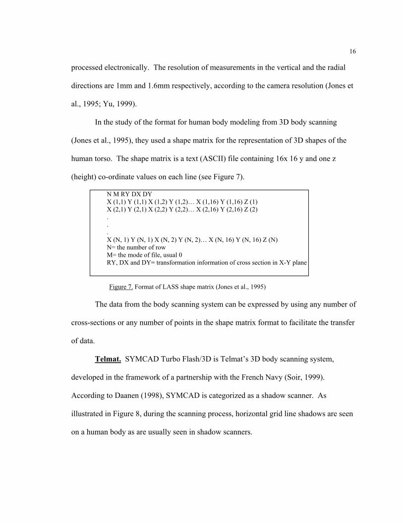
In the study of the format for human body modeling from 3D body scanning
(Jones et al., 1995), they used a shape matrix for the representation of 3D shapes of the
human torso. The shape matrix is a text (ASCII) file containing 16x 16 y and one z
(height) co-ordinate values on each line (see Figure 7).
N M RY DX DY X (1,1) Y (1,1) X (1,2) Y (1,2)… X (1,16) Y (1,16) Z (1) X (2,1) Y (2,1) X (2,2) Y (2,2)… X (2,16) Y (2,16) Z (2) . . . X (N, 1) Y (N, 1) X (N, 2) Y (N, 2)… X (N, 16) Y (N, 16) Z (N) N= the number of row M= the mode of file, usual 0 RY, DX and DY= transformation information of cross section in X-Y plane
The data from the body scanning system can be expressed by using any number of
cross-sections or any number of points in the shape matrix format to facilitate the transfer
of data.
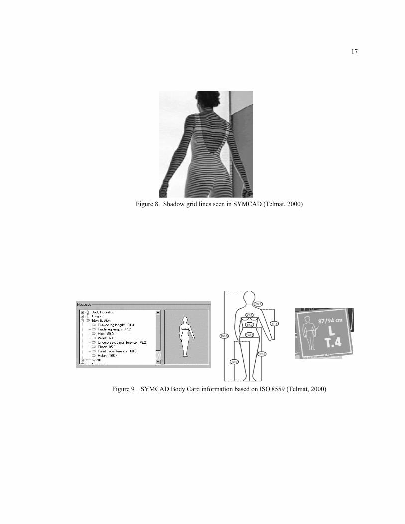
Telmat. SYMCAD Turbo Flash/3D is Telmat’s 3D body scanning system,
developed in the framework of a partnership with the French Navy (Soir, 1999).
According to Daanen (1998), SYMCAD is categorized as a shadow scanner. As
illustrated in Figure 8, during the scanning process, horizontal grid line shadows are seen
on a human body as are usually seen in shadow scanners.
Figure 7. Format of LASS shape matrix (Jones et al., 1995)
17
Figure 8. Shadow grid lines seen in SYMCAD (Telmat, 2000)
Figure 9. SYMCAD Body Card information based on ISO 8559 (Telmat, 2000)
18
The system has a size selection table based on ISO 8559 and the coordination of
integrated garment ensembles or packages. Telmat has demonstrated how measurements
could be stored and delivered to the ultimate user with their SYMCAD Body Card. The
Body card can contain critical measurements based on the ISO standard (see Figure 9).
This card has the ability to store all individual body measurements captured using the
system. The resulting measurement data can be integrated into apparel CAD systems
such as Gerber Technology’s Accumark system or Lectra System’s Modaris software.
TELMAT acquires pieces of information in 1/25th of a second. It takes 30
seconds for the cameras to move along the beams and acquire data for the whole body.
After computational calculations are made on the formed scanned image, the system is
able to generate 70 precise body measurements. It takes less than 15 seconds for the
system to extract this data. Among the data recorded are traditional measurements used
by clothing professionals, such as neck, waist, chest, bust, and hip circumferences.
White Light Scanning Systems
[TC]². The Textile Clothing Technology Corporation (TC²) has a 2T4 and a 3T6.
One of the body scanners, The 3T6, has been used at North Carolina State University for
developing apparel applications.
The [TC]² systems use white light. They developed a phase measuring
profilometry (PMP) technique for commercialization. PMP is similar to Moiré light
projection techniques, but differs from Moiré data-capture approaches in that it employs a
phase-stepping technique. According to Paquette (1996), this phase measuring
profilometry (PMP) method was thought to improve overall image resolution.
19
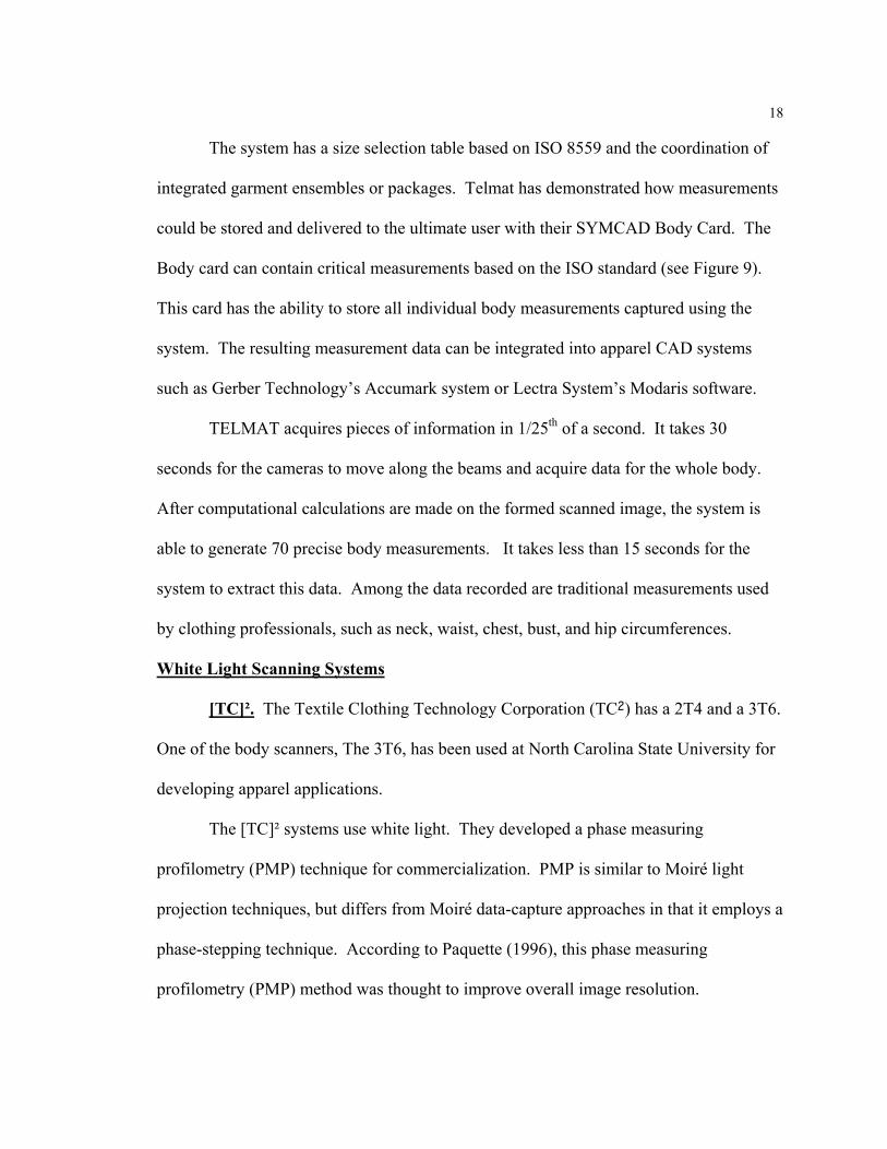
The PMP technique uses a white light source to project a contour pattern on the
surface of an object. A charge-coupled device (CCD) camera linked to a computer
detects the resulting deformed grating. The superimposed projection grating lines
interact with a reference grating, forming the fringes. As irregularities in the shape of the
target object distort the projected grating, fringe patterns result. The PMP method
involves shifting the grating preset distances in the direction of the varying phase and
capturing images at each position (see Figure 10).
Object
Projector grating and lens
Camera CCD array and lens
Intersection point (x, y, z)
Sensor head
Figure 10. [TC]²’s triangulation between projector camera and subject ([TC]², 2000)
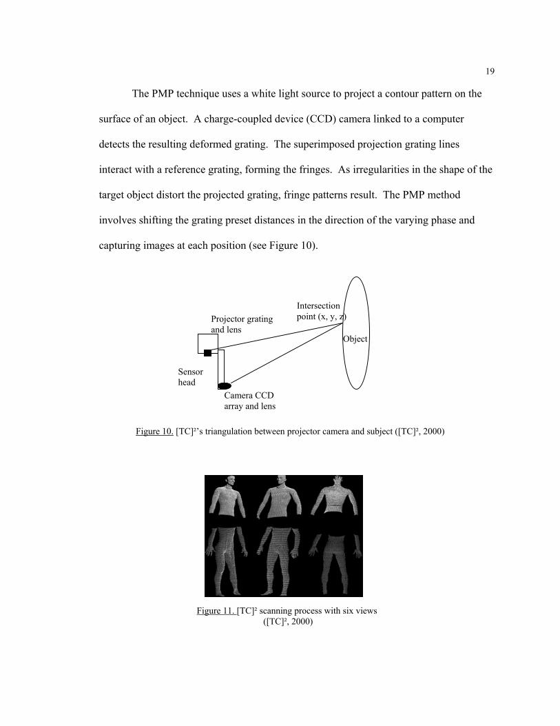
Figure 11. [TC]² scanning process with six views ([TC]², 2000)
20
A total of four images are taken for each sensor, each with the same degree of
phase shift of the projected sinusoidal patterns. Using the four captured images, the
phase of each pixel can be determined. The phase is then used to calculate the three-
dimensional data points.
As shown in Figure 11, the intermediate output of the PMP process is a data cloud
of points for each of the six views (right front, left front, and rear in both the upper and
lower part of the body). The individual views are combined by the exact orientation of
each view with respect to one another. Scanning a calibration object of known size and
orientation is an essential step in this orientation. This is known as system calibration
([TC]², 2000). The points that result from the data set are the raw calculated points
without any smoothing or other post-processing. In order for measurements to be
extracted, the data must be further processed by filtering, smoothing, filling, and
compressing. The PMP method enables faster data acquisition than laser scanning or
shadow scanning, but is unable to provide color information. According to Shentu
(1995), when analyzing human body images, the 64 color RGB file could be reduced to
the two colors of black and white allowing smaller file sizes and easier data analysis.
Even though it seems unnecessary to have color information, according to Bruner (2000),
the new 2000 model [TC]² will focus on having colors to meet the demand in the market.
Wicks & Wilson, Limited. Triform is a non-contact 3D-image capture system
from Wicks and Wilson Limited in the United Kingdom. White light (in the form of a
halogen bulb) and a variation of the “Moiré fringe technique” are used to capture the 3D
shape of an object. The 3D shape is a colored point cloud on the monitor screen that
looks similar to a photograph of the subject (see Figure 12).

21
Triform has already been tested in a large garment sizing survey in the UK
organized for Marks and Spencer. They anticipate that it will increase sales, enable
virtual displays at point of sale and in catalogue shopping, and can provide a wider range
of garments than a normal storeroom. Virtual garment try-on will also be possible in the
future. This technology is expected to have application in E-commerce for Internet
shopping, in the medical field to assist surgeons in case management and planning, in
multimedia and image manipulation, and in garment sizing for the apparel industry.
Light Emitting Diodes (LED)
Hamamatsu. The Hamamatsu Body Line (BL) scanning system uses near
infrared LED (Light emitting diodes) to obtain scan data. The system was developed to
extract three dimensional body data using fewer body landmarks and having less missing
data than other previously developed systems. Light is pulsed through a projection lens
onto the subject. Near infrared light is reflected from the subject being scanned and is
Figure 12. Triform from Wicks & Wilson (Wicks & Wilson Limited, 2000)
22
collected by the detector lens. The detector lens is a combination of spherical and
cylindrical lenses that generate a slit beam on the Position Sensitive Detectors (PSD).
According to Kaufmann (1997), the lateral-effect photodiode, also known as a position-
sensitive detector (PSD), is used to determine the position of the centroid and two PSDs
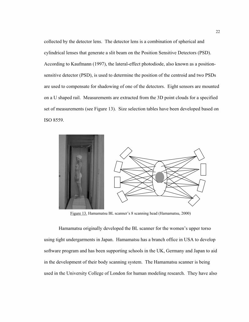
are used to compensate for shadowing of one of the detectors. Eight sensors are mounted
on a U shaped rail. Measurements are extracted from the 3D point clouds for a specified
set of measurements (see Figure 13). Size selection tables have been developed based on
ISO 8559.
Hamamatsu originally developed the BL scanner for the women’s upper torso
using tight undergarments in Japan. Hamamatsu has a branch office in USA to develop
software program and has been supporting schools in the UK, Germany and Japan to aid
in the development of their body scanning system. The Hamamatsu scanner is being
used in the University College of London for human modeling research. They have also
Figure 13. Hamamatsu BL scanner’s 8 scanning head (Hamamatsu, 2000)

23
worked with the Natick Soldier Center to compare their Body Lines system with the
Cyberware system used at Natick.
According to a study comparing the Hamamatsu BL scanner and the Natick
Cyberware Scanner (Paquette et al., 1998), the Cyberware Natick scan system generally
resulted in measurement values less than those obtained with traditional anthropometry
(TA). The Hamamatsu BL scanning system, however, tends to produce either similar or
larger circumference measurements than those observed for TA. The software performed
best on chest and hip circumference but it still has difficulty with neck circumferences.
Considering measurement variability, the results of the study indicate that the
Hamamatsu BL system tends to produce the widest dispersion of measurement values. In
the commercial apparel CAD system, Asahikasei uses this technique for body scanning,
and virtual fitting.
Other Light Based Scanning Systems
Other light based scanning systems include the 3D moiré body scanner from the
Hong Kong Polytechnic University, the PULS scanning system, Scan fit (CAD
modeling), and the Optigo 100 system. Usually light structure scanning systems are
cheaper than laser scanning systems. However, according to Yu (1999), data from light
based scanning systems is less precise because the light spot is larger.
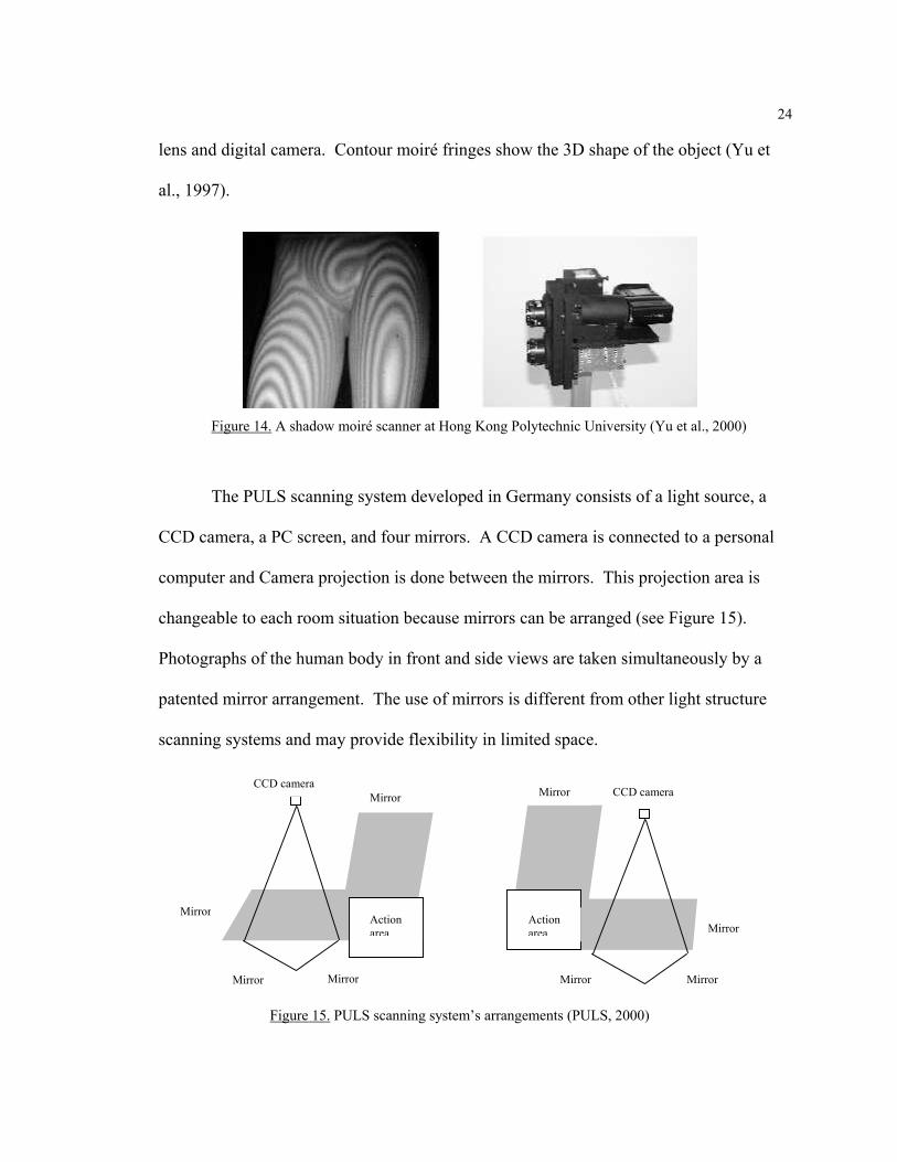
Figure 14 shows the 3D moiré body scanner developed by the institute of Textiles
and Clothing at the Hong Kong Polytechnic University. The shadow moiré technique is
based on the theory of moiré topography. The system contains a light source, two
identical grid planes with thirty line pairs, a set of projection lens, an image formation
24
lens and digital camera. Contour moiré fringes show the 3D shape of the object (Yu et
al., 1997).
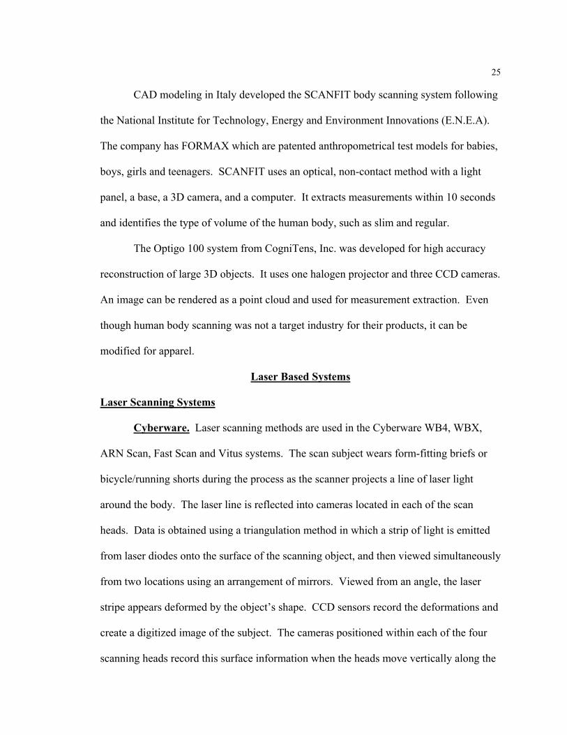
The PULS scanning system developed in Germany consists of a light source, a
CCD camera, a PC screen, and four mirrors. A CCD camera is connected to a personal
computer and Camera projection is done between the mirrors. This projection area is
changeable to each room situation because mirrors can be arranged (see Figure 15).
Photographs of the human body in front and side views are taken simultaneously by a
patented mirror arrangement. The use of mirrors is different from other light structure
scanning systems and may provide flexibility in limited space.
Figure 14. A shadow moiré scanner at Hong Kong Polytechnic University (Yu et al., 2000)
CCD camera Mirror
MirrorAction area
Mirror Mirror
CCD camera
Action area
Mirror
Mirror
Mirror Mirror
Figure 15. PULS scanning system’s arrangements (PULS, 2000)
25
CAD modeling in Italy developed the SCANFIT body scanning system following
the National Institute for Technology, Energy and Environment Innovations (E.N.E.A).
The company has FORMAX which are patented anthropometrical test models for babies,
boys, girls and teenagers. SCANFIT uses an optical, non-contact method with a light
panel, a base, a 3D camera, and a computer. It extracts measurements within 10 seconds
and identifies the type of volume of the human body, such as slim and regular.
The Optigo 100 system from CogniTens, Inc. was developed for high accuracy
reconstruction of large 3D objects. It uses one halogen projector and three CCD cameras.
An image can be rendered as a point cloud and used for measurement extraction. Even
though human body scanning was not a target industry for their products, it can be
modified for apparel.
Laser Based Systems
Laser Scanning Systems
Cyberware. Laser scanning methods are used in the Cyberware WB4, WBX,
ARN Scan, Fast Scan and Vitus systems. The scan subject wears form-fitting briefs or
bicycle/running shorts during the process as the scanner projects a line of laser light
around the body. The laser line is reflected into cameras located in each of the scan
heads. Data is obtained using a triangulation method in which a strip of light is emitted
from laser diodes onto the surface of the scanning object, and then viewed simultaneously
from two locations using an arrangement of mirrors. Viewed from an angle, the laser
stripe appears deformed by the object’s shape. CCD sensors record the deformations and
create a digitized image of the subject. The cameras positioned within each of the four
scanning heads record this surface information when the heads move vertically along the
26
length of the scanning volume. The separate data files from each scanning head are
combined in the software to produce a complete integrated image of the scanned object
(Paquette, 1996). Unlike other scanning system methods, the laser scanner generates
RGB color values, a process of identifying color-coded landmarks for data extraction
after scanning.
The U.S. Army Natick RD &E Center uses the Cyberware system to develop and
analyze body shapes for armor coverage and for other military uniform clothing. The
ARN-SCAN, also called Natick-SCAN (NS), was created using toolkits developed by
Cyberware.
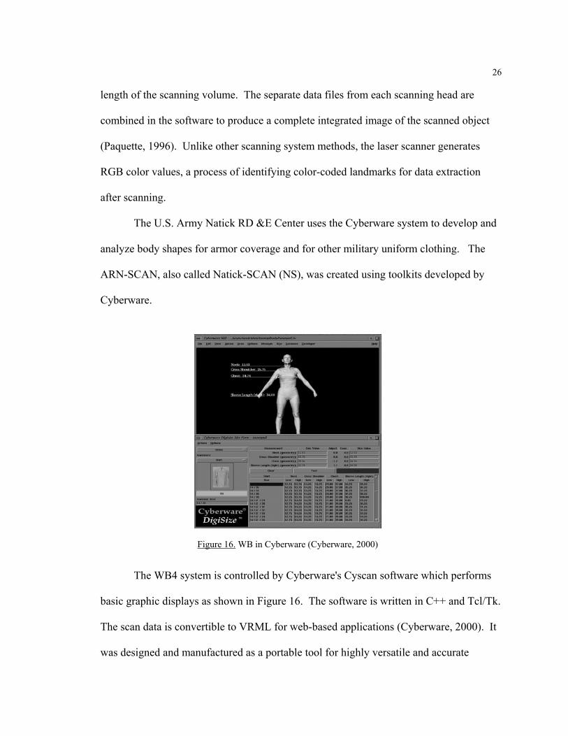
The WB4 system is controlled by Cyberware's Cyscan software which performs
basic graphic displays as shown in Figure 16. The software is written in C++ and Tcl/Tk.
The scan data is convertible to VRML for web-based applications (Cyberware, 2000). It
was designed and manufactured as a portable tool for highly versatile and accurate
Figure 16. WB in Cyberware (Cyberware, 2000)

27
scientific applications and has proven invaluable in collecting the data necessary to
develop the measurement extraction capabilities required for accurate recruit sizing.
However, the scanner has expensive features not necessarily needed on the recruit issue
line and requires skilled personnel for its setup and operation. For this reason, Cyberware
developed the WBX version of the scanner in 2000.
The WBX version of the scanner collects all of the data required for clothing
measurement extraction with a substantial reduction in complexity, size and cost. The
WBX system reduced 50% of the cycle time from 40 seconds to 20 seconds. It also
reduced the cost by 57%, from $350 thousand to $150 thousand (ARN, 2000). It has a
simpler assembly and operation than the WB4 system and includes a task optimized
motion system. The WBX was tested at the Marine Corps Recruit Depot in San Diego
during February 2000.
Both scanners are non-contact optical laser scanning systems of the surface of the
subjects. Cyberware manufactures and develops 3D body scanning systems for the
apparel industry, garment designers, anthropologists, automotive designers, furniture
designers, computer game developers, and medical applications.
TecMath. TecMath is a German company that does consulting in ergonomic
product design, vehicle design, work place design, anthropometric databases, and
statistical analysis. They also support clothing and shoe design, Made-to-Measure, and
ergonomic anthropoids, as well. The company develops software and hardware related to
ergonomics and garment measuring systems in their division of human modeling. This
company developed the RAMSIS, Contour, Move, and Vitus systems.
28
The RAMSIS system is directed at virtual product design and ergonomic analysis.
It was developed in response to the German Automotive Industry and is now used by
60% of the automotive industry worldwide. The system is integrated with CAD systems
such as CATIA, IDEAS and has applications for anthropometric databases, posture and
movement prediction, interior design, package and seat design, workplace design, and
medical design as they relate to ergonomic analysis. RAMSIS is TecMath’s ergonomic
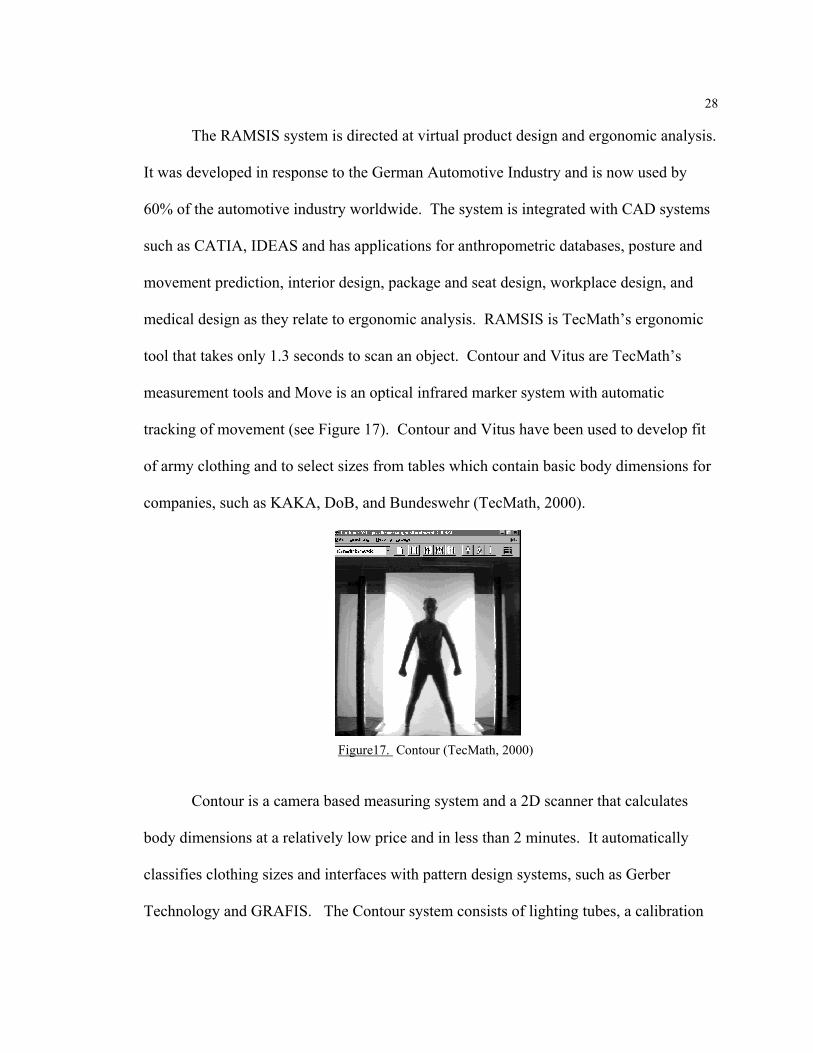
tool that takes only 1.3 seconds to scan an object. Contour and Vitus are TecMath’s
measurement tools and Move is an optical infrared marker system with automatic
tracking of movement (see Figure 17). Contour and Vitus have been used to develop fit
of army clothing and to select sizes from tables which contain basic body dimensions for
companies, such as KAKA, DoB, and Bundeswehr (TecMath, 2000).
Contour is a camera based measuring system and a 2D scanner that calculates
body dimensions at a relatively low price and in less than 2 minutes. It automatically
classifies clothing sizes and interfaces with pattern design systems, such as Gerber
Technology and GRAFIS. The Contour system consists of lighting tubes, a calibration
Figure17. Contour (TecMath, 2000)
29
plate, a CCD camera, and a frame grabber. It operates on a Windows 95 platform and a
standard PC.
Vitronic. Vitronic produces Vitus Pro, Vitus Smart, and the PEDUS 3D foot
scanner. The company focuses on the development of the “MtoM shop” for the mass
customization on the Internet. Obtained measurement data from Vitus Pro is used for
antropometric research, rapid prototyping and ergonomic research design with RAMSIS
in TecMath. Vitus Smart provides necessary measurement data for made-to-measure
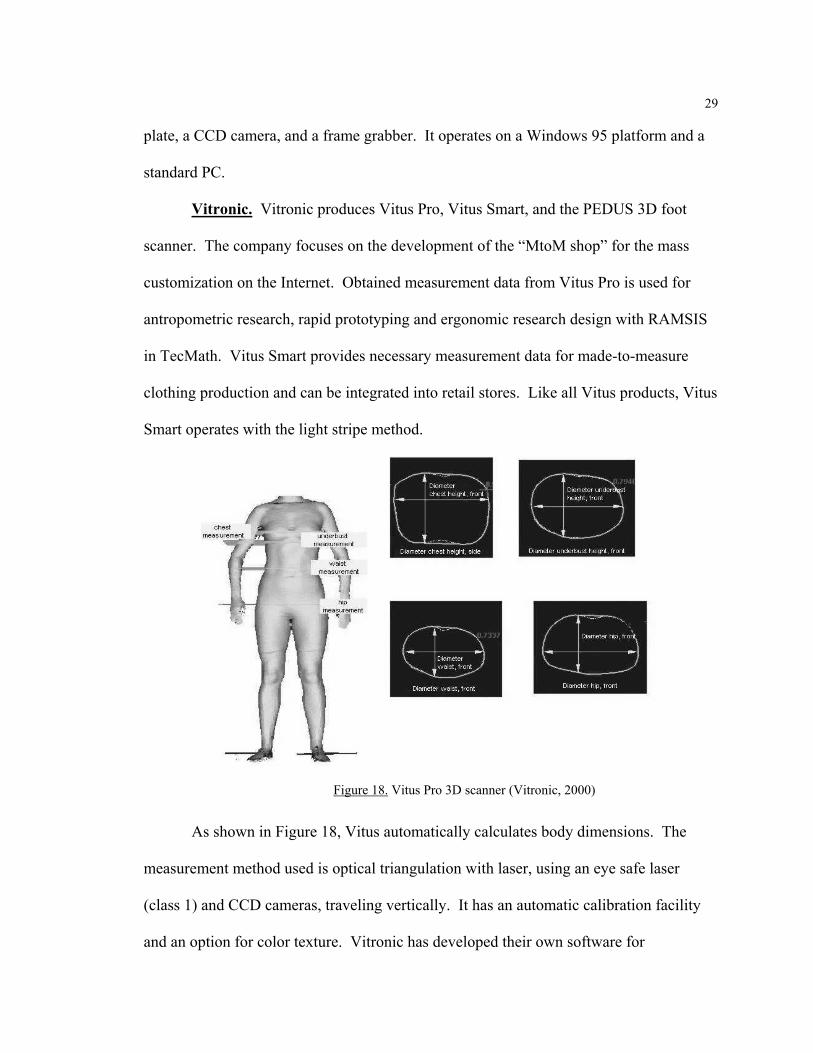
clothing production and can be integrated into retail stores. Like all Vitus products, Vitus
Smart operates with the light stripe method.
As shown in Figure 18, Vitus automatically calculates body dimensions. The
measurement method used is optical triangulation with laser, using an eye safe laser
(class 1) and CCD cameras, traveling vertically. It has an automatic calibration facility
and an option for color texture. Vitronic has developed their own software for
Figure 18. Vitus Pro 3D scanner (Vitronic, 2000)
30
visualization and manipulation of 3D scans. It allows visualization of up to 16 million
3D points, processing of textures, and data export in various formats, such as VRML and
JPG. It is a fast and precise measurement system that interfaces to CAD systems for
clothing design.
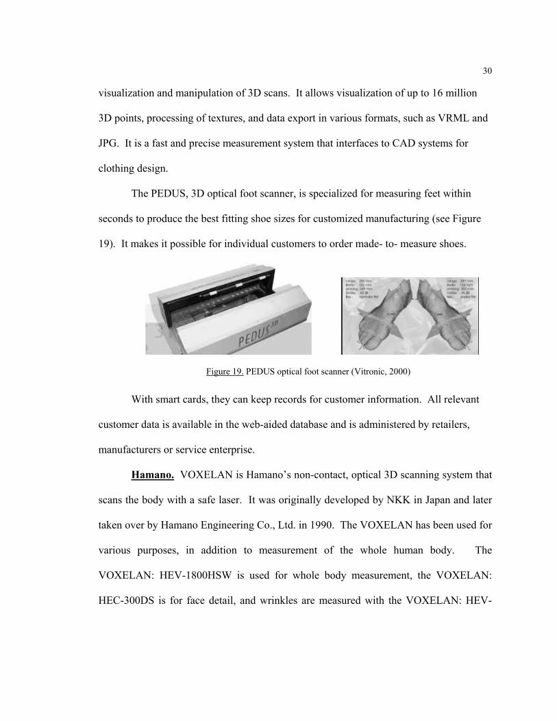
The PEDUS, 3D optical foot scanner, is specialized for measuring feet within
seconds to produce the best fitting shoe sizes for customized manufacturing (see Figure
19). It makes it possible for individual customers to order made- to- measure shoes.
With smart cards, they can keep records for customer information. All relevant
customer data is available in the web-aided database and is administered by retailers,
manufacturers or service enterprise.
Hamano. VOXELAN is Hamano’s non-contact, optical 3D scanning system that
scans the body with a safe laser. It was originally developed by NKK in Japan and later
taken over by Hamano Engineering Co., Ltd. in 1990. The VOXELAN has been used for
various purposes, in addition to measurement of the whole human body. The
VOXELAN: HEV-1800HSW is used for whole body measurement, the VOXELAN:
HEC-300DS is for face detail, and wrinkles are measured with the VOXELAN: HEV-
Figure 19. PEDUS optical foot scanner (Vitronic, 2000)
31
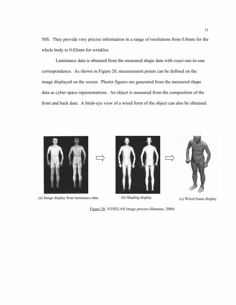
50S. They provide very precise information in a range of resolutions from 0.8mm for the
whole body to 0.02mm for wrinkles.
Luminance data is obtained from the measured shape data with exact one-to-one
correspondence. As shown in Figure 20, measurement points can be defined on the
image displayed on the screen. Plaster figures are generated from the measured shape
data as cyber space representations. An object is measured from the composition of the
front and back data. A birds-eye view of a wired form of the object can also be obtained.
(a) Image display from luminance data (b) Shading display (c) Wired frame display
Figure 20. VOXELAN image process (Hamano, 2000)
32
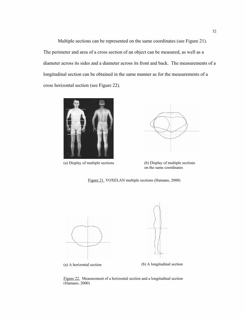
Multiple sections can be represented on the same coordinates (see Figure 21).
The perimeter and area of a cross section of an object can be measured, as well as a
diameter across its sides and a diameter across its front and back. The measurements of a
longitudinal section can be obtained in the same manner as for the measurements of a
cross horizontal section (see Figure 22).
(a) A horizontal section (b) A longitudinal section
Figure 22. Measurement of a horizontal section and a longitudinal section (Hamano, 2000)
(a) Display of multiple sections (b) Display of multiple sections on the same coordinates
Figure 21. VOXELAN multiple sections (Hamano, 2000)

33
From the measurements, solid shapes of the objects are mapped with the colors
corresponding to the heights varying from the reference position. Moreover, contour
mapping is superimposed on them by using a moiré display function. VOXELAN
software operates in a Windows 95 or NT platform and has DXF and IGES data formats,
which are used in most CAD system.
Other Laser Based Scanning Systems
The systems mentioned above are well known 3D body scanners developed to
extract measurement and image data from the human body. Other 3D scanning systems
have also been developed which may have application for the apparel industry, although
currently indirect. For example, Polhemus developed FastScan to aid in the movement of
objects. The resulting point cloud and virtual image data files can be integrated into
many CAD systems used in industrial design. 3D Scanners in London has developed
products for modeling objects. Their products, Model Maker and Reverse, are well
known for measuring and modeling in the automobile industry.
Other Scanning Systems
A Dimension 3D System
Dimension 3D-System. Dimension 3D-System in Hanover (Germany) was
founded in 1997 and has developed 3D ScanBook, 3D ScanStation, and 3D ScanStation
Body. These scanners are used for multimedia applications such as computer games,
screen design, Internet, and CD-ROM applications. The 3D ScanBook and ScanStation
have not been used for measurements, however 3D ScanStation Body has been developed
recently for computer graphics, animation and measurements.
34
The principle of 3D Scanners in the Dimension 3D-System is different from other
laser or white light activate scanning systems because the body scanning system uses a
digital camera and turntable as hardware basis and takes a shape as the silhouette
approaches. Images provided by the camera are combined in a 3D model using
Dimension 3D’s intelligent 3D ScanWare. The 3D ScanStation Body works with the
very advanced volume edit process from video images. The scanning systems contain all
components necessary for the automatic generation of a model from video images and
triangle mesh generation with arbitrary and final automatic texturing. This process is
done within seconds (Dimension 3D-System, 2000).
A Surface Tracing System
Immersion. Other methods may also be applied to scan three dimensional
objects. A company called Immersion developed a line of Micro Scribe scanners that
trace the surface of an object. These have not been used to extract measurement data but
have been used in modeling.
Some other scanning systems include Cognitens Optigo 100, Carl Zeiss, Faro
Technologies, 3D scanners and Turing 3D, none of which have applications currently for
use in the apparel industry, though they have similar modeling systems for three
dimensional objects. While these systems currently appear to have little application for
the apparel industry, who knows how they may be used as virtual enterprises develop and
e-commerce grows.
35
Advantages of Body Scanning Systems
Compared to traditional measurement methods using measuring tapes and
calipers, laser scanning systems have the advantage of speed. For example, the ARN
Scan takes 17 seconds in the initial scanning phase and results in a digitized cloud of
300,000 data points to map the body surface. Within 30 seconds, the ARN Scan software
extracts accurate measurements from the data cloud (Morton, 1999). Other advantages of
3D body scanning beyond speed are the accuracy and reproducibility of the data, as well
as the availability of new or revised measurement extraction at any time.
After the scanning process, the ARN Scan system automatically selects the
correct size for the recruit or indicates the need for a made-to-measure garment, if the
body is outside of the standardized sizing tables. ARN implemented this system for the
military at the Marine Corps Recruit Depot at San Diego, California (Morton, 1999).
Most recruits’ body shapes change drastically because of diet and exercise during their
training and the scanning system makes it possible to find the correct size for their
changing shapes, quickly.
The disadvantages of 3D scanning technology, compared to traditional
anthropometry or tape measurement methods, are the costs of the technology and the
problem with missing data because of shading. The armpits and crotch areas are often
shaded (Danen & Jeroen, 1998; Yu, 1999). Other problems are related to light absorption
by the hair and skin, movement artifacts, and data processing handling.
36
A Comparison of Scanner Specifications
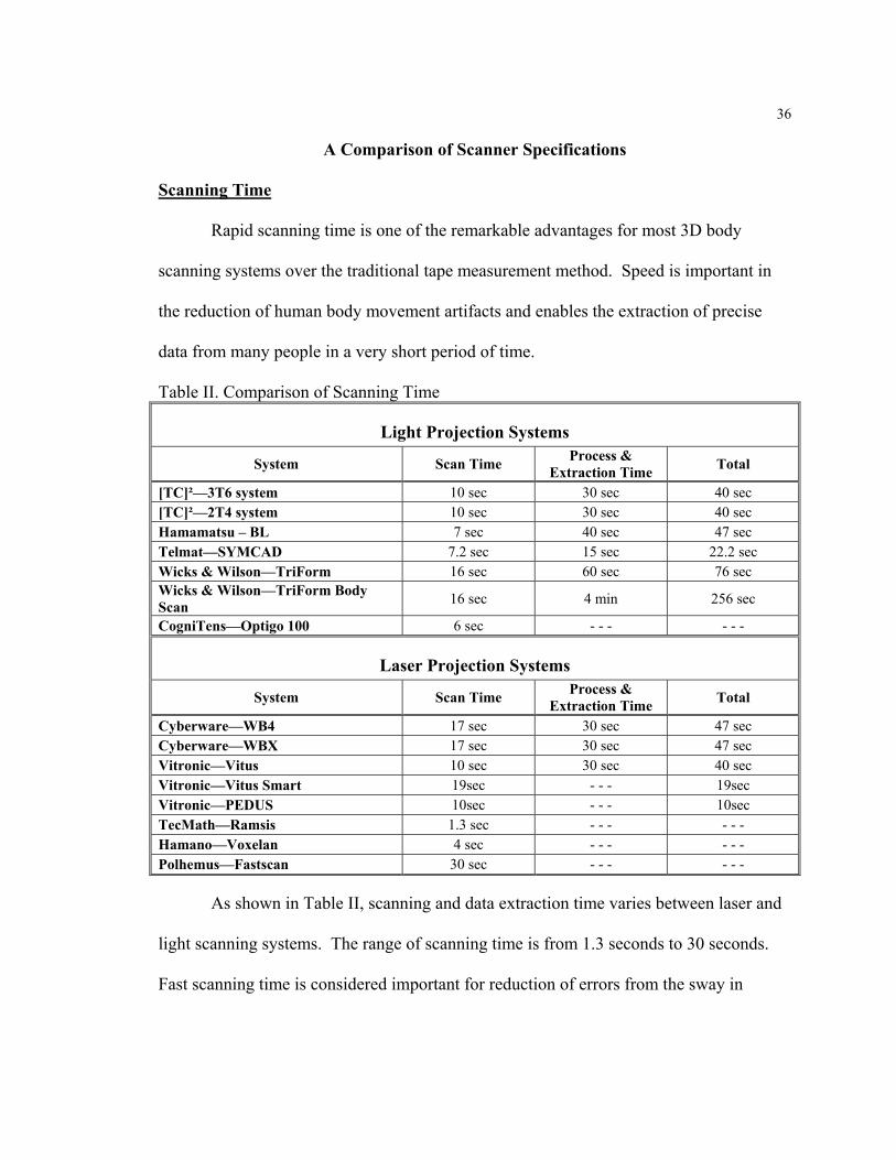
Scanning Time
Rapid scanning time is one of the remarkable advantages for most 3D body
scanning systems over the traditional tape measurement method. Speed is important in
the reduction of human body movement artifacts and enables the extraction of precise
data from many people in a very short period of time.
Table II. Comparison of Scanning Time
Light Projection Systems
System Scan Time Process & Extraction Time Total
[TC]²—3T6 system 10 sec 30 sec 40 sec [TC]²—2T4 system 10 sec 30 sec 40 sec Hamamatsu – BL 7 sec 40 sec 47 sec Telmat—SYMCAD 7.2 sec 15 sec 22.2 sec Wicks & Wilson—TriForm 16 sec 60 sec 76 sec Wicks & Wilson—TriForm Body Scan 16 sec 4 min 256 sec
CogniTens—Optigo 100 6 sec - - - - - -
Laser Projection Systems
System Scan Time Process & Extraction Time Total
Cyberware—WB4 17 sec 30 sec 47 sec Cyberware—WBX 17 sec 30 sec 47 sec Vitronic—Vitus 10 sec 30 sec 40 sec Vitronic—Vitus Smart 19sec - - - 19sec Vitronic—PEDUS 10sec - - - 10sec TecMath—Ramsis 1.3 sec - - - - - - Hamano—Voxelan 4 sec - - - - - - Polhemus—Fastscan 30 sec - - - - - -
As shown in Table II, scanning and data extraction time varies between laser and
light scanning systems. The range of scanning time is from 1.3 seconds to 30 seconds.
Fast scanning time is considered important for reduction of errors from the sway in

37
human subjects. According to Daanen (1998), increasing the scanning speed increases
the expense of vertical resolution and the electromechanical demands.
After scanning the human body, most scanning systems need extra processing
time to obtain final results of measurement data. As shown in Table II, the range of
process and extraction time is from 15 seconds up to 4 minutes. It takes slightly longer
than scanning time because the process and extraction data time involves a calibration
procedure and is computationally intensive. The lengthy calibration procedure time is
related to operating systems including software program.
Recent 3D body scanning systems are improving in the total scanning speed and
accuracy. For example, Vitronic developed a new version of 3D body scanning systems
called Vitus, Smart 3D body scanner, and PEDUS 3D foot scanner all with increased
scanning speeds. The rest of 3D scanning companies are developing fast, accurate, and
robust scanning systems. It is obvious that rapid measurement is a major advantage in
automatic 3D scanning systems over the traditional methods used manually.
Physical Dimensions of Scanning Systems
Booth size. The size of each scanner booth varies significantly from one product
to the next. This is a fairly important consideration to the apparel industry since the
anticipated placement of these systems will be in retail establishments where floor space
is extremely valuable. Table III shows each system compared by booth size, scanned
volume, and data file size of a scanned object.
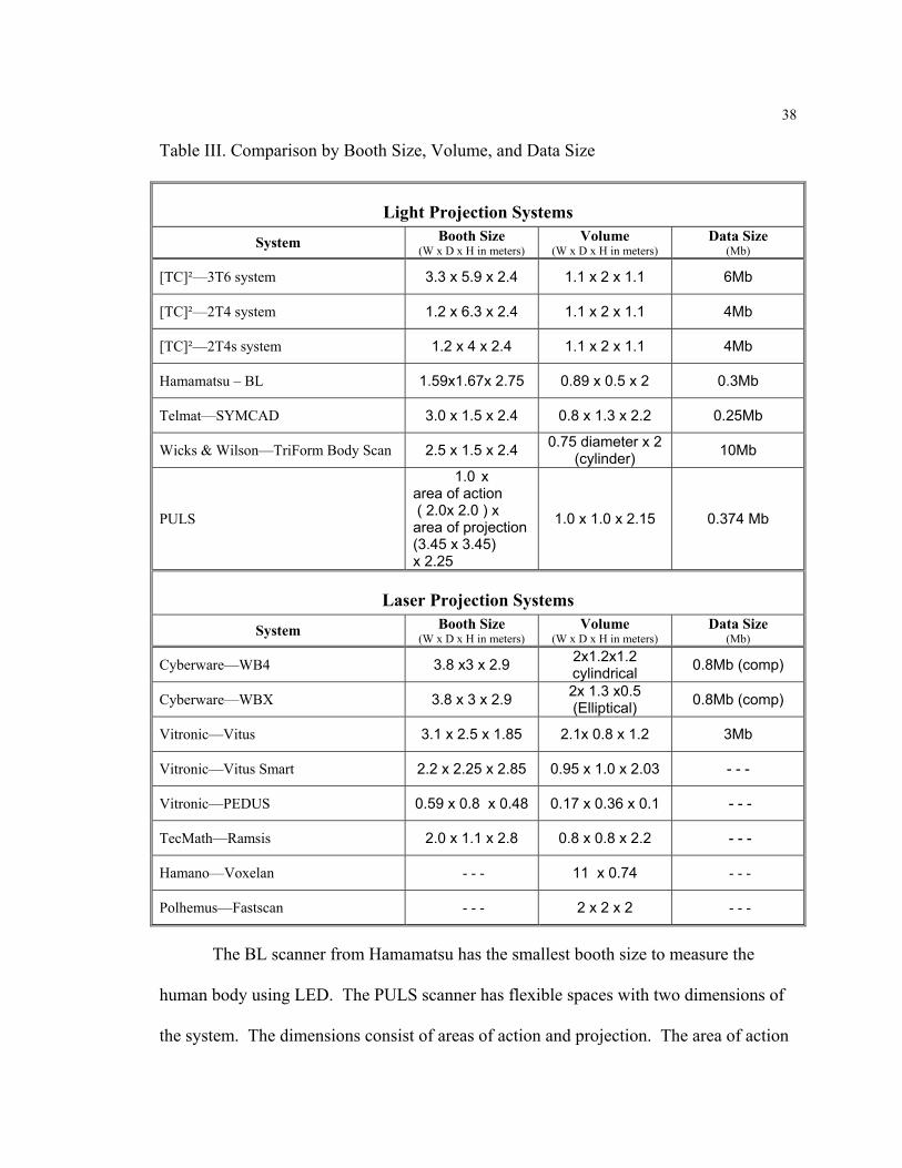
38
Table III. Comparison by Booth Size, Volume, and Data Size
Light Projection Systems System Booth Size
(W x D x H in meters) Volume
(W x D x H in meters) Data Size
(Mb)
[TC]²—3T6 system 3.3 x 5.9 x 2.4 1.1 x 2 x 1.1 6Mb
[TC]²—2T4 system 1.2 x 6.3 x 2.4 1.1 x 2 x 1.1 4Mb
[TC]²—2T4s system 1.2 x 4 x 2.4 1.1 x 2 x 1.1 4Mb
Hamamatsu – BL 1.59x1.67x 2.75 0.89 x 0.5 x 2 0.3Mb
Telmat—SYMCAD 3.0 x 1.5 x 2.4 0.8 x 1.3 x 2.2 0.25Mb
Wicks & Wilson—TriForm Body Scan 2.5 x 1.5 x 2.4 0.75 diameter x 2 (cylinder) 10Mb
PULS
1.0 x area of action ( 2.0x 2.0 ) x area of projection (3.45 x 3.45) x 2.25
1.0 x 1.0 x 2.15 0.374 Mb
Laser Projection Systems System Booth Size
(W x D x H in meters) Volume
(W x D x H in meters) Data Size
(Mb)
Cyberware—WB4 3.8 x3 x 2.9 2x1.2x1.2 cylindrical 0.8Mb (comp)
Cyberware—WBX 3.8 x 3 x 2.9 2x 1.3 x0.5 (Elliptical) 0.8Mb (comp)
Vitronic—Vitus 3.1 x 2.5 x 1.85 2.1x 0.8 x 1.2 3Mb
Vitronic—Vitus Smart 2.2 x 2.25 x 2.85 0.95 x 1.0 x 2.03 - - -
Vitronic—PEDUS 0.59 x 0.8 x 0.48 0.17 x 0.36 x 0.1 - - -
TecMath—Ramsis 2.0 x 1.1 x 2.8 0.8 x 0.8 x 2.2 - - -
Hamano—Voxelan - - - 11 x 0.74 - - -
Polhemus—Fastscan - - - 2 x 2 x 2 - - -
The BL scanner from Hamamatsu has the smallest booth size to measure the
human body using LED. The PULS scanner has flexible spaces with two dimensions of
the system. The dimensions consist of areas of action and projection. The area of action
39
includes a light background and platform, with an integrated, digital weight scale.
Standing position for the client is taken in this area and it is not changeable like other
scanners. However, the area of camera projection between the mirrors is changeable to
nearly each room situation. The WB4, WBX (3.8 x 3 x 2.9), and Vitus (3.1 x 2.5 x 1.85)
laser scanners and the 3T6 (3.3 x 5.9 x 2.4) light scanner all require bigger spaces. Most
companies are trying to reduce booth size. For example, Vitronic developed a
specialized foot scanner, PEDUS (0.59 x 0.8 x 0.48) so that they could reduce the space
of the booth, extracting only necessary measurements.
Data file size. File size becomes an important issue to consider when evaluating
data management, storage, transmittal, and use. As e-commerce capabilities develop and
intensify, smaller, more manageable files will be essential.
The range of data file size of a scanned human body is from 0.25Mb to 10Mb.
Triform needs 10Mb and [TC]² needs 6Mb to transfer or store the data of a scanned
object. However, SYMCAD (0.25Mb), PLUS (0.374Mb) and BL Scanner (0.3Mb) have
the smaller data file size of scanned object. This means their data files can easily be
transferred via electronic mail or standard 1.44 Mbytes floppy disks.
Vision Device
Although the basic triangulation technique is similar for most of the 3D body
scanners, they differ in the method of light projection and image capture. A scanning
head contains the projection system and imaging system from one viewpoint. Non-
contact optical techniques are used in the 3D body scanning systems to capture the shape
of the subject according to specific vision devices.
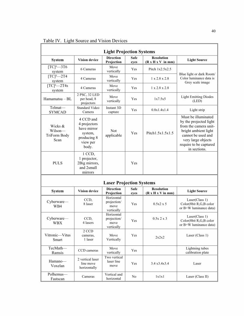
40
Table IV. Light Source and Vision Devices
Light Projection Systems System Vision device Direction
Projection Safe eyes
Resolution (R x H x V in mm) Light Source
[TC]²—3T6 system 6 Cameras Move
vertically Yes Pitch 1x2.5x2.5
[TC]²—2T4 system 4 Cameras Move
vertically Yes 1 x 2.8 x 2.8
[TC]²—2T4s system 4 Cameras Move
vertically Yes 1 x 2.8 x 2.8
Blue light or dark Room/ Color luminance data is
Grey scale image
Hamamatsu – BL 2 PSC, 32 LED
per head, 8 projectors
Move vertically Yes 1x7.5x5 Light Emitting Diodes
(LED)
Telmat—SYMCAD
Standard Video Camera
Instant 3D capture Yes 0.8x1.4x1.4 Light strip
Wicks & Wilson—
TriForm Body Scan
4 CCD and 4 projectors have mirror
system, producing 8
view per body.
Not applicable Yes Pitch1.5x1.5x1.5
Must be illuminated by the projected light from the camera unit-bright ambient light cannot be used and very large objects
require to be captured in sections.
PULS
1 CCD, 1 projector,
2Big mirrors, and 2small
mirrors
Yes
Laser Projection Systems
System Vision device Direction Projection
Safe eyes
Resolution (R x H x V in mm) Light Source
Cyberware—WB4
CCD, 8 laser
Horizontal projection/
move vertically
Yes 0.5x2 x 5 Laser(Class 1)
Color(8bit R,G,B color or B+W luminance data)
Cyberware—WBX
CCD, 4 lasers
Horizontal projection/
move vertically
Yes 0.5x 2 x 3
Laser(Class 1) Color(8bit R,G,B color
or B+W luminance data)
Vitronic—Vitus Smart
2 CCD cameras, 1 laser
Move Vertically
Yes 2x2x2 Laser (Class 1)
TecMath—Ramsis CCD cameras Move
vertically Yes Lightning tubes calibration plate
Hamano—Voxelan
2 vertical laser line move
horizontally
Two vertical laser line
move
Yes 3.4 x3.4x3.4 Laser
Polhemus—Fastscan Cameras Vertical and
horizontal No 1x1x1 Laser (Class II)
41
Vision devices used in 3D scanning include projectors, charge-coupled device
(CCD), light sources (LED, laser, etc.), and final screen resolution. As shown in Table
IV, most 3D body scanners (Cyberware, TecMath, Vitronic and Hamamatsu) project light
horizontally. In a horizontal stripe scanner, the scanning heads move parallel to the
longitudinal axis of the body. The Hamano VOXELAN scanner is the only one that uses
vertical laser stripes. The VOXELAN projects two vertical laser lines, which move over
the body in the horizontal plane. The camera is mounted steady. Some of the systems
([TC]², Telmat and Turing) have no moving components. The [TC]² and Telmat scanners
project structured light stripes on the body.
Cyberware, Vitronic, Tecmath, Polhemus and VOXELAN (Hamano) use lasers.
The advantage of a laser strip scanning system is that only one line needs to be analyzed,
unlike light projection ([TC]², Telmat, LASS, Contigentis, PULS, and Hamamatsu).
When Laser strip scanning systems are used on the human body, the laser must be
classified as Class I for eye safety. Except for the Polhemus (Class II) system, not
currently used in body scanning, available 3D laser scanners are safe.
In the Cyberware, Vitronic and Hamamatsu systems, cameras or mirrors are
mounted above and below the projection system. This enables the capture of data for the
top of the head and the chin area. In the TecMath scanner the cameras are mounted only
above the laser projector. This means that the lower side of some body parts may not be
well represented.
The Hamano VOXELAN has cameras mounted at a fixed position between
rotating laser projectors. Body parts like the shoulders and crotch do not show up very
well, due to camera positioning. The [TC]² 3T6 system uses six projectors and cameras;
42
three for the upper part of the body and three for the lower part. The front of the body is
captured by four cameras and the back by two cameras. As the viewpoint of the scanning
head is lower than the shoulder, the top of the shoulder may not show up very well.
Both Telmat and Hamano scan the subject twice. First, the front of the body is
scanned and then the back is scanned. Hamano merges the data by using markers on the
shoulders. Telmat merges the data by “gluing” the front and back scans on the shadow
scan of the body. The disadvantage of this procedure may be image distortion since there
is no control for posture differences during the front and back scans (Daanen & Jeroen,
1998).
In order to capture the whole body with structured light, the projector and cameras
have to be placed at a significant distance from the body, or multiple scan heads must to
be used. The first option increases the size of the total scanning system, unless mirrors
are used. Therefore, some companies such as [TC]² use separate scanning heads for the
upper and lower part of the body. In the Cyberware scanner, the cameras are integrated
into a single unit. Mirrors above and below the laser project their images on a single
CCD device. Puls uses four mirrors and the primary advantage of this arrangement is
that fewer cameras are needed, however, the complexity of the analysis increases.
Missing data is a significant problem for most 3D body scanning systems.
Shading appears to contribute to this problem. Generally, an increase in the number of
cameras used, combined with strategic lighting, reduces the amount of missing data.
43
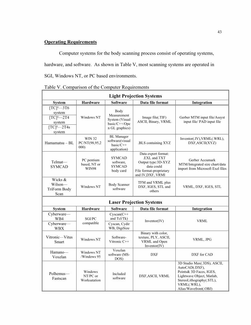
Operating Requirements
Computer systems for the body scanning process consist of operating systems,
hardware, and software. As shown in Table V, most scanning systems are operated in
SGI, Windows NT, or PC based environments.
Table V. Comparison of the Computer Requirements
Light Projection Systems System Hardware Software Data file format Integration
[TC]²—3T6 system
[TC]²—2T4 system
[TC]²—2T4s system
Windows NT
Body Measurement
System (Visual basic/C++/Open GL graphics)
Image file(.TIF) ASCII, Binary, VRML
Gerber MTM input file/Assyst input file/ PAD input file
Hamamatsu – BL WIN 32
PC/NT(98,95,2000)
BL Manager software(visual
basic/C++ application)
.BLS containing XYZ Inventor(.IV),VRML(.WRL),
DXF,ASCII(XYZ)
Telmat—SYMCAD
PC pentium based, NT or
WIN98
SYMCAD software,
SYMCAD body card
Data export format: .EXL and.TXT
Output type:3D-XYZ data could
File format-proprietary and IV,DXF, VRMI
Gerber Accumark MTM/Integrated size chart/data import from Microsoft Exel files
Wicks & Wilson—
TriForm Body Scan
Windows NT Body Scanner software
TFM and VRML plus DXF, IGES, STL and
others VRML, DXF, IGES, STL
Laser Projection Systems System Hardware Software Data file format Integration
Cyberware—WB4
Cyscan(C++ and Tcl/Tk)
Cyberware—WBX
SGI/PC compatible Cyscan, Cydir
WB, DigiSize
Inventor(IV) VRML
Vitronic—Vitus Smart Windows NT Software-
Vitronic C++
Binary with color, texture, PLY, ASCII,
VRML and Open Inventor(IV)
VRML, JPG
Hamano—Voxelan
Windows NT /Windows 95
Voxelan software (MS-
DOS) DXF DXF for CAD
Polhemus—Fastscan
Windows NT/PC or
Worksatation
Included software DXF,ASCII, VRML
3D Studio Max(.3DS), ASCII, AutoCAD(.DXF), Points& 3D Faces, IGES, Lightwave Object, Matlab, StereoLithography(.STL), VRML(.WRL), Alias/Wavefront(.OBJ)
44
Data format is one of the main keys to determine feasibility of integration into
apparel manufacturing systems. According to Jones (1995), format of the data file for
exchange between different hardware and software platforms should be written in plain
text. In the CAD domain, two widely used text file formats are Initial Graphics
Exchange Specification (IGES) and Auto CAD’s DXF. However, most current CAD
systems developed for apparel pattern makers use DXF based on AAMA standards, often
distinguished as AAMA DXF files.
Companies in the direction of the mass customization are also looking for the
possibility of exporting measurement data to all major apparel CAD pattern programs
including companies including Gerber, Lectra, Assyst, and Scanvec for use in made to
measure and custom alteration application. For example, Vitronic,Telmat, [TC]², and
Wicks & Wilson are developing software program for automatic size selection and mass
customization in apparel.
The development of software is very important for the 3D body scanning system
to extract useful data automatically, accurately and consistently. Each company
developed their own software programs such as Cyscan, Cydir WB, digisize
(Cyberware), BL scanner software (Hamamatsu), Voxelan software (Hamano), and Body
Measurement System ([TC]²), SYMCAD software, Body cards (Telmat), Body Scanner
software (Wicks and Wilson), RAMSIS, and Contour software (Tecmath), and Vitronic
software (Vitronic).
The WB4 system is controlled by Cyberware's Cyscan software that performs
basic graphic displays. The software is written in C++ and Tcl/Tk. The scan data is
convertible to VRML for web based applications. The Cyberware and other research
45
groups from Ohio University, Clemson Apparel Research, Anthrotech, HAAS Tailoring
Co., and Southern Polytechnic State University were participated in ARN task for
development for ARN scan. And also BRC worked to incorporate its software functions
into ARN scan, which is a derivative of Cyberware’s Cyscan. Cyscan controls the WB4
and performs basic graphic displays.
SYMCAD and [TC]² both mention that they have the capability to integrate into
Gerber Technology Accumark MTM CAD systems. The Accumark Made-to-Measure
(MTM) system, a Gerber Garment Technology CAD package, employs a Windows PC
for custom order entry and an 800 workstation for direct conversion of size information
into custom-fit patterns and production markers. Batch processing allows a single step
process from order-entry to plotting and cutting (Dewitt, 1994).
The SYMCAD system is controlled using a PC Pentium with Windows NT or
Windows 98. Data file format is done with a proprietary format and IV, DXF, VRML
and the output type is a 3D XYZ data cloud. The system is integrated with size charts
and the garment size data can be imported from Microsoft Exel files. The SYMCAD
software is customized with the customers’ data and it is available in various languages.
[TC]² runs their Body Measurement System using on Windows NT, which was
programmed using in C++, visual basic, and Open GL graphics. The Body Measurement
System that included software program was created by the Textile Clothing Technology
Corporation ([TC]²) and was used for mass customization of apparel.
Automated measurement extraction offers an advantage over manual digitization
given the increased speed and reduced data processing costs it affords, especially for
large data sets. The data file format is an image file such a TIF, ASCII, Binary, and
46
VRML and can interface with most CAD system in apparel such as Gerber MTM,
Assyst, and PAD input files.
As shown in Table V, the BL Scanner software (Hamamatsu), Triform Body
Scanner software (Wicks &Wilson), and FastScan (Polhemus) can be integrated with the
DXF data file format that is used in most Auto CAD systems. The BL Scanner software
was developed by University College in London under sponsorship of Hamamatsu.
TriForm developed software that they have called “BodyScanner software” used
for capture and alignment. Additional software may be required by Triform to view the
body image. The operating system is mainly Windows NT4. For display, SVGA
supports true color mode, 1024x 768 resolution, with the size as large as possible (Wicks
and Wilson Limited, 2000). A single point cloud 3D image file is produced in one of
Wicks and Wilson’s TFM formats. This data can also be output in a number of other
formats appropriate to the intended application such as DXF for CAD, STL for rapid
prototyping and VRML for Internet visualization.
Vitus and Vitus Smart are operated in the Windows NT environment that Vitronic
software has developed and programmed with C++. File formats are done with binary
and PLY. Export formats are ASCII, VRML and Open Inventor. The basic software
package allows for fast visualization and processing of the scan data with all PCs which
run windows. The data can be exported as VRML and JPG files for presentations and
further processing. Cyberware, [TC]², and Triform also have VRML which will enable
integration with the web.
More software packages are available and have been developed in research
centers. Examples are a): the ARN-SCAN software developed under the DLA-ARN
47
program, b) DataSculpt by Laser Design, c) SHAPE ANALYSIS developed by Beecher
Research Company, and d) 3DM developed by CAR (Clemson Apparel Research).
Software such as SHAPE ANALYSIS (Beecher) and TECMATH-VITUS has been
written to manually extract anthropometric measurements from pre-marked digitized
images. Clemson Apparel Research (CAR) has been working software development for
3D whole body scans.
Clemson University developed the 3DM software package in 1991. It takes 3D
whole body image files in text format and provides the user with a function to display,
manipulate, segment, analyze, and measure the image. It is written in C++, uses OpenGL
and X-Windows libraries, and runs on both an SGI workstation running Unix and on a
PC running Windows NT (Pargas et al., 1998).
According to Pargas (1998), the 3DM software has the benefits of the accuracy,
consistency, and reliability of body measurement and improves quality of garment fit. It
also increased measurement speed. For automatic measurement extraction, 3DM proceed
to extract measurements based on the identified landmarks. 3DM is currently being
refined for Tom and Linda Platt, Inc. of New York City for use in the design and
development of high-end fashion women’s garments. It has also been considered for use
with the scanner under development by [TC]².
The 3DM reads image files generated by any scanner that generates points in the
form (x, y, z) where x, y, and z are the point coordinates in 3D. This includes files
generated by a Cyberware WB4 scanner and [TC]² Body measurement system Scanner.
The software allows a user to edit a 3D image, display and manipulate the image,
48
manually identify, select and segment regions, manually select landmarks on the body,
and using the landmarks, extract anthropometric measurements specified by the user.
Dimension 3D-System developed 3D ScanBook for Window 9X, 3D ScanStation
for Window 9X or Window NT, and 3D ScanStation Body for Window NT. The
geometry of 3D format files can be provided and exported as a volume model or point-
cloud. The following data formats are available: Open SPX, VRML1, VRML2,
Wavefront OBJ, 3DS, Softimage and DXF without texture (Dimension 3D system,
2000).
This company provides two kinds of software, which are Open SPX Applet and
Open SPX Plugin for the 3D online shop. 3D scanners create true-life 3D models within
minutes with the 3D Plugin for Netscape Navigator and Internet 3D models and the 3D
models can easily be presented on users’ screen. Both software programs are free to use.
Open SPX applet requires neither download nor installation. We can just add the Applet,
call to html-source, and get started. Netscape 4.x or MS Internet Explorer 4.0 is required.
3D scanners in this company are mainly used for image scan with 3D data (Dimension
3D system, 2000).
Dimension 3D's scanning technology and Dimension 3D Open SPX Plugin are
used for online shopping such as Alcatel(mobiles), Xverse (Clothing), Otto(shoes), and
Mc Neill(Schoolbags). As an example of virtual shopping online, Xverse displays
various styles of pants and T-shirts by using the Dimension 3D Open SPX-Plugin.
Even though the Dimension 3D has not yet used for measurement data, three
dimensional body scanning systems with the development of software program shows
other potential for use on line.
49
Conclusion and Suggestions
This research attempted to search all currently available 3D body scanning
systems in order to find out if the scanning systems could be used for the apparel
industry. Even though there are problems yet to be solved that will impact the adoption
of this technology, clearly, this technology has promise as a tool in efficient measuring of
human bodies for mass customization of apparel. The three dimensional scanning
systems have the advantages of speed, accuracy and consistency of measurement. In
addition, technical measurements are simply extracted without professional knowledge of
traditional measurement methods.
The currently available 3D body scanning systems are based on optical
triangulation by non-contact methods, which would attract people to use body scanners.
However, most halogen light scanning systems have limitations due to missing data on
under arms or chins, as well as surface reflectance and noisy fringes. One possible
explanation is that light properties of translucency and reflection cause missing data. Use
of mat black tape or special clothing might assist in the reduction of light reflection from
shinny skin. Vision devices such as CCD and light projectors are also important to
reduce the missing data due to shading effects. With the development of software
programs, increases in number of cameras used, and the refining of light projection
techniques, the limitation might be overcome.
The scanning time in any type of 3D body scanning systems was much faster than
in traditional measurement methods. Even though light projection systems reported
faster scanning times than laser scanning systems, the total scanning time including
50
calibration and extraction did not show significant differences. These results might be
related to their calibration software programs.
In this study, most companies said that they developed their own software
program package. C++ was commonly used to develop software program in the
Cyberware, Vitus, [TC]² and BL scanners. However, different data file formats were
found. Cyberware used inventor file formats. Hamamatsu used BLS, a proprietary
format containing ASCII and Intensity value. [TC]² used ASCII, Binary, VRML, and
image file formats. Wicks & Wilson used TFM, VRML, DXF, IGES, and STL formats.
Vitronic used Binary, PLY, ASCII, VRML and open inventor formats.
[TC]² and SYMCAD showed high potential for integration into apparel CAD
systems with Gerber Accumark MTM input file. Vitronic, Hamamatsu, Wicks & Wilson,
and Polhemus might also have the ability to integrate with DXF files for AutoCAD,
which is commonly used in the industry. However, ASCII files have been suggested for
the process of integration since DXF files are differently defined in many apparel CAD
companies.
As I consider these various types of the data file formats used currently in three
dimensional body scanning systems, a great deal of work remains to be done related to
integration of extracted measurements into apparel CAD systems. First, I emphasize that
development of extraction software programs for apparel is essential to improve accuracy
and consistency of measurement data. Second, clear measurement definitions and
standards between apparel industries and companies developing 3D body scanning
systems are strongly suggested for the development of the software programs in order to
extract critical measurements, to match correct sizes, and to improve accuracy and

51
consistency. Third, the new measurement method has to be simple to use for people in
the apparel industry. And finally, reducing or eliminating the landmarking process,
missing data, and inconsistencies related to movement artifacts are still goals held by
most of the developers of this technology.

52
References
Arai, Y., Yekozeki, S., & Yamada, T. (1991). 3-D automatic precision measurement
system by liquid crystal plate on moiré-topography. SPIE Moiré techniques,
Holographic interferometry, Optical NDT, and Applications to Fluid Mechanics,
1554B, 266-274.
ARN (2000, March). ARN redesigned 3-D whole body scanner-WBX for recruits
clothing issues [On-line].
Available: http://arn.iiti.org/docs/scan/systems/wbxwar.htm
Bouguet, J. & Perona, P. (2000, April). 3D photography on your desk department of
electrical engineering [On-line].
Available: http://www/vision.caltech.edu:80/bouguetj/ICCV98/.index.html
Business Wire (2000, August 30). RealityBUY.com set to develop a virtual garment
showroom for idealpath.com, internet application provider to the apparel and textile
industries. [On-line] Available E-mail: [email protected].
Bruner, D. (2000, May). Application of body scanning technology. Paper presented at
the seminar of the College of Textiles in North Carolina State University, Raleigh,
NC.
CAESAR (1999, December 10). CAESAR uses latest laser technology [On-line]. Available: http://www.sae.org/technicalcommittees/caelaser.htm
Cyberware (2000, April). DigiSize whole body measurement software [On-line].
Available: http://www.cyberware.com/wb-vrml

53
Daanen, H. A. M., & Jeroen van de Water, G.(1998). Whole body scanners. Displays,
19, 111-120.
Dimension 3D system (2000, November). Dimension 3D systems [On-line].
Available: http://www.dimension-3d.com
Dewitt, J.W. (1994, December). CAD players reposition products. Apparel Industry
Magazine, 55 (12), 50-60.
Hamamatsu (2000, February). Hamamatsu brochures. Natick, MA: Author.
Hamano (2000, April). VOXELAN system specifications. Japan: Author.
HUMAG (2000, September). Human Measurement, Anthropometry and Growth
Research Group [On-line].
Available: http://www.lboro.ac.uk/servide/ero/ic/01centers/humagGB.html
Jones, P., Li, P., Brooke, W. K., & West, G. M. (1995). Format for human body modeling
from 3-D body scanning. International Journal of Clothing Science and Technology,
7 (1), 7-16.
Kafri,O. & Glatt, I.(1990). The physics of moiré metrology, New York: A Wiley-
Interscience publication.
Kaufmann, K. (1997, May). Invasion of the body scanners. IEEE Circuits & Devices, 13
(3)12-17.
Lovesey, E. J. (1974, March). The development of a 3-dimensional anthropometric
measuring technique. Applied Ergonomics, 5(1), 36-41.

54
Mittelhauser, M. (1997, August). Employment trends in textiles and apparel:1973-2005.
Monthly Labor Review, 120 (1), 24-33.
Morton, L. (1999, June 3). Joint electronic commerce program office [On-line].
Available: http://arn.iitri.org/docs/scan/systems/ecpr.htm
Paquette, S. (1996, September). 3D scanning in apparel design and human engineering.
IEEE Computer Graphics and Applications, 16 (5), 11-15.
Paquette, S., Brantley, J.D., Corner, B.D., Li, P., & Oliver, T.(1998). Automated
extraction of anthropometric data from 3D images. Natick, MA: U.S. Army Soldier
Biological & Chemical Command.
Pargas, R. P., Staples, N. J., Malloy, B. F., Cantrell, K. & Chatriwala, M., (1998). Titled
planes in 3D image analysis. SC, USA: Clemson University, Department of
Computer science [On-line].
Available: http://arn.iitri.org/ftr/cu06/cu06.html
Pargas, R.P.(1998). Automating Information Extraction from 3D Scan Data Clemson
University, DLA-ARN T2P5 Project report.
PULS. (2000, November). PULS brochures. Germany: Author.
Shentu, K. (1995). The research of using laser holography to measure three-D human
bodies size, Proceeding of the 3rd Asian Textile Conference, I, 295-299.
Soir, F. (1999, June 29). Made- to Measure for everybody [On-line].
Available: http://www.symcad.com
[TC]² (2000, January). [TC]² [On-line]. Available: http://www.tc2.com/products

55
TecMath (2000, April). TecMath human modeling [On-line].
Available: http://arn.iitri.org/docs/scan/articles/techmath
Telmat (2000, April). SYMCAD [On-line].
Available: http://www.symcad.com/eng/ENGindex.htm
Vitronic (2000, December). VITUS [On-line].
Available: http://www.vitus.de/english/index.html
Wicks and Wilson Limited (2000, March 16). BodyScanner specification [On-line].
Available: http://www.wwl.co.uk/tfmbodyscannerspec.htm
Yu, W. (1999, October). 3-D body scan-a new measure of size and shape, ATA Journal,
69-70.
Yu, W., Harlock, S. C., Leaf, G. A.V., & Yeung, K.W. (1997). Instrumental design for
capturing three-dimensional moiré images, International Journal of Clothing Science
and Technology, 9(4), 301-310.
Yu, W., Ng, R., Hu, J., Gu, H., & Yan, S. (2000). Development of a moiré body scanner
for automatic jeans pattern, Hong Kong Polytechnic University [On line].
Available: http://www.asd.polyu.edu.hk
Xverse (2000, November). Xverse [On-line]. Available: http://www.xverse.com