thorium-based nuclear fuel - robert b....
TRANSCRIPT

IAEA-TECDOC-412
THORIUM-BASED NUCLEAR FUEL:CURRENT STATUS AND PERSPECTIVES
PROCEEDINGS OF A TECHNICAL COMMITTEE MEETINGON UTILIZATION OF THORIUM-BASED NUCLEAR FUEL:
CURRENT STATUS AND PERSPECTIVESORGANIZED BY THE
INTERNATIONAL ATOMIC ENERGY AGENCYAND HELD IN VIENNA, 2-4 DECEMBER 1985
A TECHNICAL DOCUMENT ISSUED BY THEINTERNATIONAL ATOMIC ENERGY AGENCY, VIENNA, 1987

THORIUM-BASED NUCLEAR FUEL:CURRENT STATUS AND PERSPECTIVES
IAEA, VIENNA, 1987IAEA-TECDOC-412
Printed by the IAEA in AustriaMarch 1987

PLEASE BE AWARE THATALL OF THE MISSING PAGES IN THIS DOCUMENT
WERE ORIGINALLY BLANK

The IAEA does not normally maintain stocks of reports in this series.However, microfiche copies of these reports can be obtained from
IN IS ClearinghouseInternational Atomic Energy AgencyWagramerstrasse 5P.O. Box 100A-1400 Vienna, Austria
Orders should be accompanied by prepayment of Austrian Schillings 100,-in the form of a cheque or in the form of IAEA microfiche service couponswhich may be ordered separately from the INIS Clearinghouse.

FOREWORD
A number of IAEA Member States have extensive thorium resources, insome cases bigger than uranium resources and they are interested in thedevelopment of thorium nuclear fuels for the reason of self-sufficiency.The world situation with uranium production could be also one of thefactors endorsing R and D on further investigation of thorium fuels.
Until the present time considerable efforts have already been madein the area of fabrication, utilization and reprocessing of Th-basedfuels for different types of reactors, namely: by FRG and USA - for HTRs;FRG and Brazil, Italy - for LWRs; India - for HWRs and FBRs. Basicresearch of thorium fuels and thorium fuel cycles are also beingundertaken by Australia, Canada, China, France, FRG, Romania, USSR andother countries. Main emphasis has been given to the utilization ofthorium fuels in once-through nuclear fuel cycles, but in some projectsclosed thorium-uranium or thorium-plutonium fuel cycles are alsoconsidered.
Thorium fuel utilization, technical status and development needswere considered in detail by the INFCE Working Group 8 (1977-1980). Someaspects of the thorium fuel cycle were considered at the IAEA NuclearPower Conferences in Salzburg (1977) and Vienna (1982), as well as, theTCM on Improved Utilization of Water Reactor Fuel with Special Emphasison Extended Burnups and Plutonium Recycling (Mol, Belgium, 7-11 May1984), TCM on Advanced Light and Heavy Water Reactor Technology (Vienna,Austria, 26-29 November 1984) and others. In-depth consideration of thetechnology of some thorium fuels was given at the IAEA Advisory Group onAdvanced Fuel Technology and Performance (Wurenlingen, Switzerland, 4-7December 1984).
The purpose of the Technical Committee on the Utilization ofThorium-Based Nuclear Fuel: Current Status and Perspective was to reviewthe world thorium resources, incentives for further exploration, obtainedexperience in the utilization of Th-based fuels in different types ofreactors, basic research, fabrication and reprocessing of Th-basedfuels. As a result of the panel discussion the recommendations on future

Agency activities and list of major worldwide activities in the area ofTh-based fuel were developed.
The Agency wishes to thank all those who participated in the paneldiscussion. Special thanks are due to the Sessions' Chairmen,Messrs. M. Peehs, I. Slcsarev, C. Ganguly and the IAEA staff members,Messrs. F. O'Hara and M. Ugajin. The officer of the IAEA responsible forthe preparation of this document is Mr. V. Onufriev, Division of NuclearFuel Cycle.
EDITORIAL NOTE
In preparing this material for the press, staff of the International Atomic Energy Agencyhave mounted and paginated the original manuscripts as submitted by the authors and givensome attention to the presentation.
The views expressed in the papers, the statements made and the general style adopted arethe responsibility of the named authors. The views do not necessarily reflect those of the govern-ments of the Member States or organizations under whose auspices the manuscripts were produced.
The use in this book of particular designations of countries or territories does not imply anyjudgement by the publisher, the IAEA, as to the legal status of such countries or territories, oftheir authorities and institutions or of the delimitation of their boundaries.
The mention of specific companies or of their products or brand names does not imply anyendorsement or recommendation on the part of the IAEA.
Authors are themselves responsible for obtaining the necessary permission to reproducecopyright material from other sources.

CONTENTS
PAPERS PRESENTED
An overview of world thorium resources, incentives for further exploration and forecast forthorium requirements in the near future ................................................................ 7K. M. V. Jayaram
IAEA activities in nuclear fuel technology, performance and utilization including the role ofthorium-based fuel .......................................................................................... 21V. Onufriev
Thorium utilization in PWRs: status of work in the cooperative Brazilian/German program ... 27M. Peeks, G. Schlosser, R.B. Pinheiro, V. Ma/y, M. Hrovat
Thorium cycle in unmodified PWRs ....................................................................... 45G. Gambier, H. Schaeffer
Thorium utilization in solving the nuclear power fuel problem ....................................... 597.5. Slesarev, A.C. Morozov, D.F. Tsurikov
Basic research on utilization of thorium-based nuclear fuel ............................................ 67J.H. Zhang, B.R. Bao, Y.X. Xia, G.Q. Wang, J.B. Zhu
Thorium oxide blanket fabrication for Indian fast breeder test reactor .............................. 73P. Balakrishna, B.P. Varma, R. Rajendran, K. Balaramamoorthy
Reprocessing and refabrication of thorium-based fuel .................................................. 89E. Zimmer, C. Ganguly
Operative experience in first campaign for reprocessing of uranium-thoriumElk-River fuel elements .................................................................................... 113T. Candelieri
SUMMARY OF PAPERS .................................................................................... 133
SUMMARY OF THE PANEL DISCUSSION ........................................................... 139
Annex I. STATUS OF US PROJECTS RELATED TO THORIUM UTILIZATION ......... 145
Annex II. CURRENT STATUS OF THE THORIUM FUEL RESEARCH PROGRAMMEIN JAPAN ... . . . . . . . . . . . . . . . . . . . . . . . . . . . . . . . . . . . . . . . . . . . . . . . . . . . . . . . . . . . . . . . . . . . . . . . . . . . . . . . . . . . . . 147
Annex III. THORIUM RESOURCE STUDIES IN AUSTRALIA .... . . . . . . . . . . . . . . . . . . . . . . . . . . . . . . . 149
Annex IV. NUCLEAR DATA FOR Th-232 AND U-233 ..... . . . . . . . . . . . . . . . . . . . . . . . . . . . . . . . . . . . . . . . 151
List of participants . . . . . . . . . . . . . . . . . . . . . . . . . . . . . . . . . . . . . . . . . . . . . . . . . . . . . . . . . . . . . . . . . . . . . . . . . . . . . . . . . . . . . . . . . . . . . 161
PAPERS PRESENTED
AN OVERVIEW OF WORLD THORIUM RESOURCES,INCENTIVES FOR FURTHER EXPLORATION ANDFORECAST FOR THORIUM REQUIREMENTSIN THE NEAR FUTURE
K.M.V. JAYARAMAtomic Minerals Division,Department of Atomic Energy,Hyderabad, India
Abstract
Thorium occurs in asociation with uranium and rare earthelements in diverse rock types. It occurs as veins of thorite, urano-thonte and monazite in granites, syenites and pegmatites. Monazitealso occurs in quartz-pebble conglomerates, sandstones and f luvia-tile and beach placers. Thorium occurs along with REE in bastnae-site, in the carbonatites.
Present knowledge of the thorium resources in the worldis poor because of inadequate exploration effor ts arising out ofinsignificant demand. But, with the increased interest shown byseveral countries in the development of Fast Breeder Reactorsusing thorium, it is expected that the demand wil l increase consi-derably by the turn of the century.
The total known world reserves of Th in RAR categoryare estimated at about 1.16 million tonnes. About 31% of this(0.36 mt) is known to be available in the beach and inland placersof India. The possibility of f inding pr imary occurrences in thealkaline and other acidic rocks is good, in India. The other countrieshaving sizeable reserves are Brazil, Canada, China, Norway,U.S.S.R., U.S.A., Burma, Indonesia, Malaysia, Thailand, Turkeyand Sri Lanka.
Considering that the demand for thorium is l ikely to incre-ase by the turn of this century, it is necessary that data collectedso fa r , globally, is pooled and analysed to ident i fy areas thathold good promise.
Introduction:
Thorium in association with uranium and Rare Earth Ele-ments (REE) occurs in diverse rock types; as veins of thorite,thonanite, uranothonte and as monazite in granites, syenites,pegmatites and other acidic intrusions. It also occurs as an asso-ciated element with REE bearing bastnaesite in carbonatites.Monazite also occurs in quartz-pebble conglomerates, sandstonesand in f luv ia t i l e and beach placers.

Prior to the second world war thorium was used widelyin the manufacture of gas mantles, welding rods, refractoriesand in magnesium based alloys. Its use as fuel in nuclear energy,in spite of its limited demand as of now and low forecast, isgaining importance because of its transmutation to 233 u. Severalcountries like India, Russia, France and U.K. have shown consi-derable interest in the development of fast breeder reactors (FBR)and it is expected that by the turn of this century some of thecountries would have started commissioning large capacity units.
2. World deposits;
Present knowledge of the Thorium resources is poor becauseof the relatively low-key exploration efforts arising out of insigni-ficant demand. For the same reason the possibility of discoveringnew finds in addition to increasing the known resources containedin the deposits already known is good.
The largest known reserves of thorium are contained inthe beach and inland placer deposits of monazite, which is exploitedso far for its REE content (55-60% REO).
Monazite placers are reported from Australia, Egypt, India,Liberia, Brazil, Malgachi and the United States of America (Flo-rida). In Brazil, monazite occurs associated with ilmenite andzircon along the eastern and southeastern Atlantic coast [1], Italso occurs at Araxa in association with carbonatites. In Burma,placer deposits derived from the weathering of biotite granitesoccur in the southern Shan states. Considerable quantities ofcassiterite and wolframite occurring in these placers are derivedby the weathering of quartz veins and pegmatite dykes injectedinto the granites.
Malaysian deposits occur on the coast of Kedan and Perlisat Pulan Lankawi and Seremban. Monazite associated with colum-bite and xenotime occurs in Ulusempam area near Pahang. Cassi-terite placers at Trengganu contain as much as 58% monazite.The occurrences of monazite in Thailand and Indonesia are similarto the occurrences in Burma [2; 3].
In Sri Lanka rich deposits derived by the weathering ofschists, granulites and gneisses occur along the N and N W coast.Alluvial deposits also occur in the lower valley of Kaleganga inRatnapura district. The largest placer deposit (12,000 t) nearPulmoddai extending over a distance of 3 km. and a width of50 m. contains 3 million t of sand at 0.4% monazite, 18% rutileand 62% ilmenite [3].
In Bangladesh monazite is also reported to occur in thebeach placers (derived from granites) near Chittagong. Similardeposits are also reported to occur in Southern China, betweenChianhua Hsien in South Western Hunan province to Kung ChenHsien in northeastern Kwangsi province. Extensive deposits arealso reported from Kwangtung province.
In Canada, large Thorium reserves associated with Uranium(with Th:U ranging from 3.5 to 1 to 0.5:1) occur in Elliot Lakearea and other Huronian complexes. Thorium is also reported

from the granitic and syenitic rocks in the Bancroft area of Onta-rio. Many occurrences of this type are reported from theGrenville geological province, the Charlebois Lake and the LaRonge areas in Saskatchewan. It also occurs at Oka in associationwith uranium and niobium in the carbonatites in Qubec [^]. InTurkey, the Eskisehir-Sivrihisar area is estimated to contain 880thousand t of Thorium.
In USA about 80% of the known Th reserves occur in veintype thorite deposits in the Lemhi Pass area of Idaho and Montanaand in the Western mountains of Central Colarado. Large reservesof Th are also known to occur associated with bastnaesite in themassive carbonatite deposits of California [4]. The Florida beachplacers wherefrom monazite could be recovered along with iimeniteare estimated to contain 0.3% to 1% monazite [4].
The details of world reserves and production are givenin Table I and Figure 1.
TABLE I
WORLD THORIUM RESERVES AND PRODUCTION(Based on USBM Mineral Industry Survey, May 16, 1985)
In thousands of tonnes
Name of the country Reserve Base ProductionRAR
520* 17.038.01.1
0.2
0.21.56n. a.
1.2.
3.
4.
5.
6.7.
8.
9.
10.
11.
United States of AmericaAustralia
Brazil
CanadaIndiaMalaysia
NorwayOMEC
OPEC
ChinaU.S.S.R.
200
40
70
240
360
10
150
55
35
@380*@120
Total 1,160 37.5
* Bastnaesite
n.a. - not available
@ excluded.

• BEACH L FLUVUTILEA VEIN TYPE THORITE DEPOSITS 7S
CARBONATfTE DEPOSITS
THORIUM DEPOSITS IN THE WORLD
FIG. 1.

3. Thorium occurrences in India:
Although many occurrences of uranothorite, thorite, thoria-nite and monazite are reported from in several intrusive pegma-tites and younger granites of all ages, monazite occurring in thebeach and inland placers remains the main thorium and REEbearing mineral source assessed by AMD (Fig. 2).
I OSRINAGARI
ERHAMPUR
SAKHAPATNAMHYDERABAD
OCUNTALAPUOI'. ' THORIUM OCCURRENCES
IN
INDIATHORIFEROUS AREAS
... MIXED URANIFEROUS AND•••* THORIFEROUS AREAS
**»* AERORADIOMETRICANOMALIES
FIG. 2.
11

The occurrence of monazite in the placers (assessed sofar at 4.5 x 10* t) may be divided into 4 types: (i) the Beachand Dune sands on the West and East coasts (42%); (ii) the Teris(16%); (iii) the sea bed (10.0%) and (iv) inland placers (32%).
3.1 Beach sands:
Although monazite occurs associated with ilmenite andother hm in the beach sands, skirting the entire Peninsular India,its economic concentration is confined to only some areas wheresuitable plhysiographic conditions exist. The west coast placersare essentially beach or barrier deposits with development ofdunes where aeolin action is prominent in dry months. On theother hand, the east coast deposits consist of extensive dunesfringing the coast.
3.1.1. West coast
Of the several west coast deposits assessed so far thedeposits at Chavara and Manvalkurchi in Kerala and Tamil Nadurespectively, are rich in hm content [5]. The other deposits occurr-ing north of Chavara, stretching over a distance of 50 km. uptoRatnagiri are leaner with a hm content of -^^. 20% of which mona-zite forms 0.06% [6].
3.1.2 Origin of West Coast deposits;
Physiographically the peninsular India on the west coastmay be divided into three divisions: (i) the 25-40 km. wide westernghats which rise steeply to an average height of 1200 m. abovem.s.l. along a conspicuously straight faul t (ii) the 20-30 km. widenarrow coastal strip (30 m. high) to the west, drained by 41 fastwest flowing rivers and (iii) the narrow (45 km. wide) continentalshelf with an average depth of 29 fathoms.
The western ghats receive about 3000 mm. of ra infal lannually. All west flowing rivers are small and descend into thenarrow coastal belt to finally empty into irregular, labile network of estuaries and lagoons. The beaches along the coast areabout 3 to 4 m. high.
Geologically, the western uplands consist of ortho andpara gneisses of Precambrian age, charnockites of felsic to ultra-mafic composition and leptynites, intruded by swarms of pegma-tites. Overlying these Precambrian rocks are the Tertiary Quilon-Warkala beds consisting of latérites, semi-consolidated sandstonesand clays with lenses of lignite. They vary in thickness and dip3° seaward. Overlying these beds asre the recent unconsolidatedalluvial clays and estuarine sands.
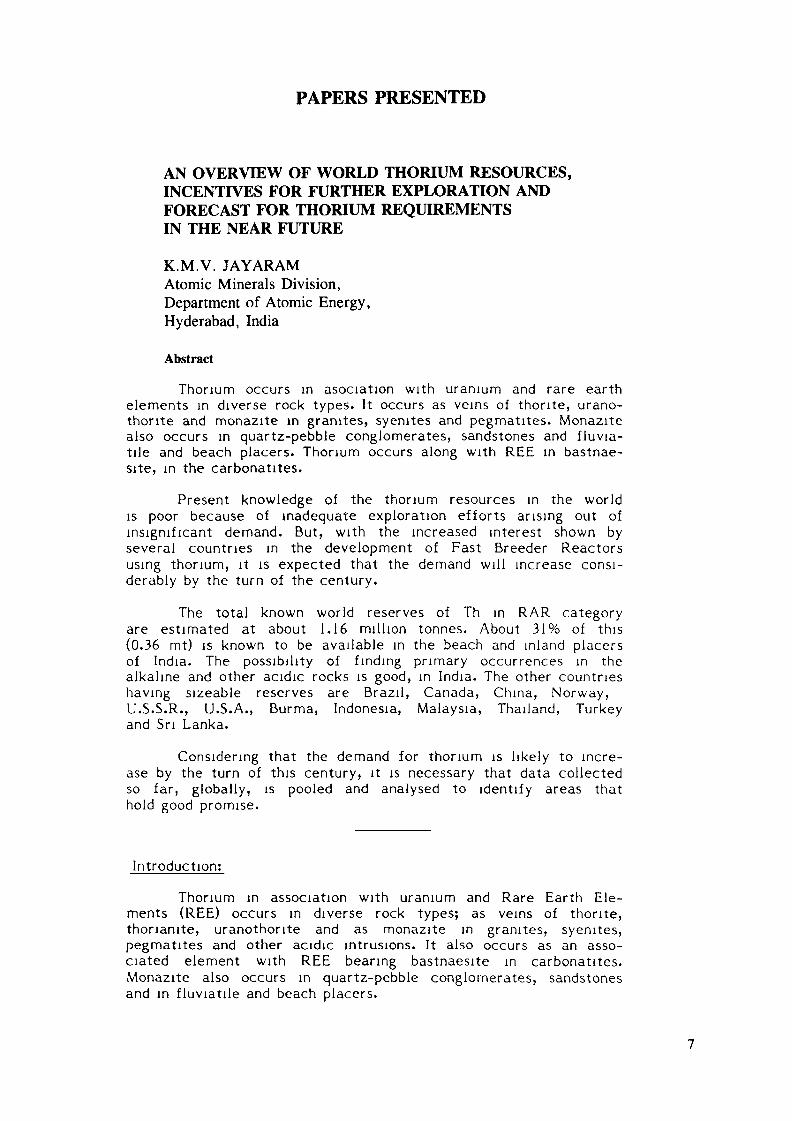
A series of uplifts of western ghats shifted the strandline seaward resulting in the formation of bars, spits and lagoons[7]. The hm deposits are formed in four successive stages: (i) late-ritisation of gneissic complexes, (ii) successive mountain up l i f tand simultaneous seaward shift of strand line., (iii) reworkingof the beach sands by sea waves, which rise often to a heightof 3 m. in 12 s. period and (iv) littoral d r i f t caused by the breakingof the waves far away from the shore and consequent northerlymovement of lighter minerals along the reflected waves. The
12
______»It JUMt DAK Of CMS«Of ». W MONSOON
_____'« 0€C WITMOÄAWM.Of S. W MONSOON
•MADURAL
SHEYAGUNGA"-̂ .
ERKU MUKAIYU. I .>
WIND CURRENTS7 TO 11 km P H
13 TO 18 Um P H
19 TO 26 km P H
DAILY DIRECTION
SEA CURRENTS
APE COMORIN
NOV. DEC JAN.
FEB MAR APR
MAY JUNE JULY
AUG SEPT OCT BATHY-METRIC CHART OF WEST COAST
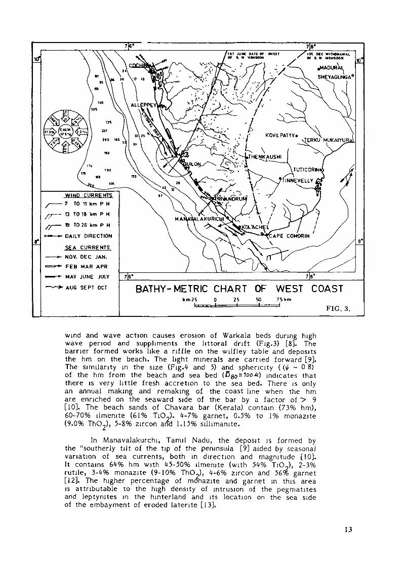
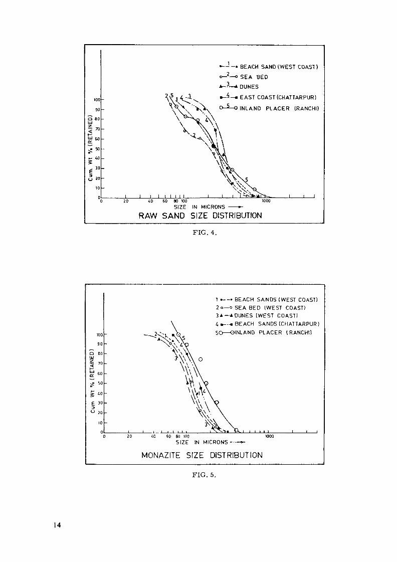
wind and wave action causes erosion of Warkala beds during highwave period and supphments the littoral drift (Fig.3) [8]. Thebarrier formed works like a riffle on the wilfley table and depositsthe hm on the beach. The light minerals are carried forward [9].The similarity in the size (Fig.4 and 5) and sphericity ( ( ^ - 0 8 )of the hm from the beach and sea bed (Bgo-loo*) indicates thatthere is very little fresh accretion to the sea bed. There is onlyan annual making and remaking of the coast line when the hmare enriched on the seaward side of the bar by a factor of > 9[10]. The beach sands of Chavara bar (Kerala) contain (73% hm),60-70% ilmenite (61% TiOj. 4-7% garnet, 0.5% to 1% monazite(9.0% ThO2), 5-8% zircon and 1.15% sillimamte.
In Manavalakurchi, Tamil Nadu, the deposit is formed bythe "southerly tilt of the tip of the peninsula [9] aided by seasonalvariation of sea currents, both in direction and magnitude [10].It contains 64% hm with 45-50% ilmenite (with 54% TiOJ, 2-3%rutile, 3-4% monazite (9-10% ThOj, 4-6% zircon and 56% garnet[12]. The higher percentage of monazite and garnet m this areais attributable to the high density of intrusion of the pegmatitesand leptynites in the hinterland and its location on the sea sideof the embayment of eroded latente [13].
13
100
90
O 80LU
"60
~ 40
O 20
10
•---• BEACH SAND (WEST COAST)
o-2—o SEA BED
A--3—* DUNES
•~4_, EAST COAST (CHATTARPUR)
O-5—O INLAND PLACER (RANCHI)
20l l l l l l l
60 80 100SIZE IN MICRONS
1000
RAW SAND SIZE DISTRIBUTION
FIG. 4.
1 •——• BEACH SANDS (WEST COAST)2 o—o SEA BED (WEST COAST)3A-A DUNES (WEST COAST)4«—«BEACH SANDS (CHATTARPUR)SO——OINLAND PLACER (RANCHI)
20 £0 60 60 100SIZE IN MICRONS
MONAZITE SIZE DISTRIBUTION
FIG. 5.
14

3.1.3 Dunes:
The dunes near Manavalakurchi situated at the mouth ofVailiyar river are formed by aeolin action on the beaches dur ingthe dry season. They contain 50% hm of which 35% is ilmenite(55% TiO2), 1.35% rutile, and 3.3% monazite (9-10% ThC>2) [1*].
3.1.4 Sea bed off the Neendakarai-Kayankulam bar;
Investigations conducted about 600 m. off the Neendakarai-Kayankulam bar over a length of 22 km shows that the sea bedcontain 5% hm of which 0.05% is monazite (9.5% ThOJ [15].
3.1.5 The Teris:
The 'teris' are dunes formed by aeolin action in the arid,rain shadow plains east of western ghats. Typically, these dunesanalyse upto 10% hm of which 3-4% is ilmenite and 0.06% to0.35% is monazite [15].
3.1.6 The East Coast deposits;
The east coast beach placers and dunes are low gradewith 8-20% hm. Their formation is influenced by the northerlylong shore currents and the consequent annual littoral d r i f t ofabout 2 million t of sand containing 4-5% hm. The sedimentsf rom eastern ghats, which consist of charnockites, khondalitesand alkali rocks, are carried by east flowing rivers and depositedto form deltas and shallow beaches. During the low tide the bea-ches f rom the surf zone are exposed to strong, incessant windaction during summer months and cause accretion and landwardmigration. Of the several occurrence studied the Chatrapur deposit(Orissa) with about 20% hm and 0.5% monazite is important
The origin of these dunes may be traced to theinitial building up of off-shore bars/spits resulting in the formationof frontal dunes and lagoons. Subsequently, the lagoons are filledby the deposition of fresh burden f rom local streams and spillover sand from frontal dunes and also the littoral drift . This resultsin the formation of low undulating inter dunes sandy area andf ina l ly the rear landward dunes wherever land barriers exist [17].
In addition to the Chatrapur occurrences several exploitabledeposits (25-30% hm; 0.2% monazite) occur along the east coast,in Andhra Pradesh and Tamil Nadu.
4. Inland placers;
Significant occurrences of monazite-bearing inland placerdeposits are located in the Ranchi plateau. The bed rocks in theregion comprise of Archean metasediments profusely injectedby aplo-pegmatites and finally by a porphyritic granite (18). Thebed rock is covered by a 11/2 m thick mantle of coarse, yellowalluvium with thin discontinuous dark bands which contain 2-10%hm of which 0.45% to 1.0% is monazite.
15
5. Primary sources;
In addition to the placer deposits described above severalprimary occurrences of Th are noted at many places.
Of these, possible economic concentrations that mightmerit economic consideration in future are: (i) Proterozoic quartz-pebble conglomerates overlying the Archean basements., (ii) Jura-ssic sandstones of Kutch in Gujrat and the Gondwana sandstonesin M.P., (iii) The igneous rocks of Dhabi, Jajawal (M.P.), Palamau(Bihar) along a 150 km long shear zone, (iv) The pegmatites ofSalem District (Tamil Nadu) intruding biotite schists and (v) Thealkali syenites and carbonatites of Sevattur, Pakkanadu (TamilNadu), Sung Valley (Meghalaya), Khammam & Visakhapatnam (A.P.),Kishengarh (Rajasthan) and several other occurrences.
6. Reserves:
The current knowledge of thorium reserves in the worldis small. In Brazil, several monazite placers occur on the Atlanticcoast. In addition large reserves (87%) are associated with bastnae-site in Araxa carbonatites. In Canada 2^0 x 10 t of thorium re-sources are identified so far, bulk of which are associated withuranium (Th:U 3.5:1/0.5:1) in the quartz-pebble conglomeratesof Elliot lake. In South Africa, of 12500 t of Th identified, about77.5% is estimated to occur in the carbonatites, 11.2% in thesandstones of Karoo supergroup, and only 5% in the quartz-pebbleconglomerates and the rest as veins in Archean complex.
China and USA have a large reserve base because of theassociation of Th (0.5% to 1% ThO2) with REO in its bastnaesitedeposits associated with carbonatites. The Chinese reserve asso-ciated with the bastnaesite in the carbonatites of Inner Mangoliaare estimated at 380,000 t of Th [19].
According to USBM Industrial survey (1985), [20] the USreserves of thorium are estimated at about 200,000 t of which,about 70% occurs in vein type thorite deposits. The reminderare in the carbonatite deposits in California. Small amount ofmonazite (0.35%) are also recovered alongwith ilmenite, fromthe beaches of Florida.
The reserve base of other countries like Sri Lanka,Malaysia,Norway etc. are small and forms only 20% of the world total.
In India thorium reserves are estimated at 0.36 x 10 tof Th forming ^ 30% of the known world resources [21]. Thedetails of Indian reserves are given in Table-II.
7. Process flowsheet:
A generalised industrial process flowsheet for the separationof individual minerals is given in Figure 6. It comprises of fiveunit operations: (i) sizing, (ii) magnetic separation of varying inten-sity, (iii) high tension separation (HT), (iv) air/wet tabling and(v) flotation.
16

TABLE II
RESERVES OF MONAZITE
In million tonnes
NatureRAR EAR I
Monazite ThO- Monazite ThO-
1. Beach sandsand dunes
2. Tens
1.60 O.IM
0.73 0.066
0.29 0.026
3.
k.
Sea bed off coast
Inland placers
Total
O.i>3 0.038
l.H 0.130
2.33 0.210 2.16 0.1 9<*
BEACH SAND
FINE
MAGJSEP
* IDRY
ISCREEN 30 ft
DUNE SAND(PRE CONCENTRATION)
ISPIRALS
PRE CONC- MID TAILS
i————I SPIRALS
PRE CONC MIOI L_
TAILS*
COARSE*(SHELLS ETC REJECT)
MAG N MAG.l l
-COND NCONDSCREEN 50*T L
I
N CONO N COND COND
*H T S
1
1AIR TABLE
I——CONC
CONCMAG SEP
I ICOARSE* FINES(REJECT)
TAILS CONCI *
FLOTATIONI
FROTH TAILSI *
WET TABLE
MAG CONC MID TAILS*
MAG*
__ , IIRUTILE! [GARNET] IMONAZITE!
GENERALISED FLOW SHEET WEST COAST BEACH SANDFIG. 6.
17

The raw sand is trucked to the plant where it is driedand sized using 35 mesh screen. The oversize is rejected and theundersize is treated in HT separators. The conducting mineralsare subjected to magnetic separation (light intensity) to yielda crop of ilmenite in the magnetics and rutile in the non-magnetics.The non-conducting minerals are subjected to a successive stagesof light and high intensity magnetic separation to yield monazitein the magnetics which is cleansed by using air/wet tabling and/orflotation to the required grade. The non-magnetics of high intensitymagnetic separation are cleaned on an air table to yield a con-centrate of zircon and lights (tails) of silliminite. Silliminite isfur ther cleaned using fatty acid flotation to obtain a marketablegrade crop. Though ideally ilmenite and rutile must report asconducting magnetics and non-magnetics, several minerals, parti-cularly garnet reports in these concentrates. Therefore, severalsteps of cleaning and scavenging are undertaken to yield and requi-red grade of monomineralic concentrates and increase the recoveryof individual minerals.
In case of low grade Dunes and east coast placer deposits,tests using several alternative equipment such as Tables, Trays,Cones and Spirals indicated that spirals are most satisfactorysince they offer flexibility and also yield a rejectable tailing analy-sing 2.9% hm and a concentrate (75% hm at 90% recovery), whichcould be fed to the dry mill.
8. Discussion:
The reasonably assured resources of thorium in India,form about 31% of the world's estimated deposits. The reservescould have been several times more if systematic surveys arecarried out for thorium in the geologically promising terrainssuch as we have in the acid intrusive belt of Salem in Tamil Nadu,the hinterland of Kerala and the alkali syenitic and carbonatiterocks of Tamil Nadu, Andhra Pradesh, Rajasthan, Madhya Pradesh,Bihar and Meghalaya.
Taking an overview, while intensive and extensive explo-ration identified 2 x 10 t of U in RAR category, the known tho-r ium reserves, assessed so far in the same category indicate1.2 x 10 t even when the inputs for locating thorium reservesare incidental to prospecting for hm like ilmenite and/or uranium.Therefore, globally speaking the possibility of increasing the Threserves is high.
Long term projections of IAEA for the nuclear power growthfor the period 2025 indicates an inadequate supply [22] of uraniumeven when a lower growth rate for nuclear energy (using LMFBR)and the planned growth of uranium production are considered.The gap will increase considerably, if the demand for nuclearenergy increases and more reactors are commissioned.
While it is true that large stocks of available depletedU can be utilised, countries that have limited identified resourcesof U, may have to use Th to ensure continuous growth rate intheir quest for power.
18

Thus, in the long term, it is necessary that the data collec-ted globally is pooled, and prospective areas are identified forfunding of surveys that might be considered rewarding.
9. Acknowledgements;
My grateful thanks to Dr. R. Ramanna, Chairman, AEC,India, for giving me this opportunity to represent India on thiscommittee. Thanks to Sri T.M. Mahadevan, Director, AMD, forhis valuable suggestions.
Thanks are also due to several geologists and mineral engi-neers who poineered the work and developed the techniques forassessing and processing the beach placers.
REFERENCES
[I] OECD.NEA/IAEA., Uranium Resources, Production andDemand. 1973.
[2] Proc. int. Conf. on Peaceful uses of Atomic Energy. Vol.2.1958. 91.103.716.721.7*5.
[3] Proc.int. Conf. on Peaceful uses of Atomic Energy. Vol.6.1955.129.147.176.178.562.
[4] Mineral Facts and Problems. U.S. Dept. of Commerce.,1980. 937.
[5] Viswanathan, P., Studies on Travancore beach sands. Ind.Min. 3our. 1957. 109.
[6] Dhanunjaya Rao,G. AMD report (unpublished). 1965-66
[7] Prabhakara Rao, G., Some aspects of placer deposits ofSouth Kerala in relation to the geomorphic evolution ofWest Coast of India. D.Sc. thesis. 1962.
[8] Jayaram, K.M.V. and Krishnaswamy, R., Study of sedi-mentation phenomenon on SW coast of India. I.S.A. 1962.
[9] Gilson, J.H., Sand deposits of titanium minerals. Min. Eng.1959. Vol. 2.4. 421-429.
[10] Udas, G.R., Jayaram, K.M.V., Ramachandran, M and San-karan, R., Beach sand placer deposits of the world vs.Indian deposits. Plant maintenance and import substitution.1978.35.
[ I I ] Prabhakara Rao, G., Ramachandran, M. and Rama Rao,D.N. AMD report (unpublished) 1969-1977.
[12] Narayan Das, G.R., AMD report (unpublished). 1952-53.
[13] Ramachandran, M., Geology and distribution of heavy mine-ral placers on the west coast. AMD report (unpublished).1977.
19

Sankaran, R.N. and Jayaram, K.M.V., A study of the Dunesnear Manavalakurchi for assessing their heavy mineraipotential. AMD report (unpublished). 1978.
[15] Chakravorty, N., Rajagopal, M.K., Kidwai, S.M., Jayaram,K.M.V., and Krishnaswamy, R., Assessment of heavy eco-nomic minerals and quality of light minerals as back fillfrom the off-shore samples in the area Neendakarai toKayankulam. AMD report (unpublished). 1962.
[16] Sankaran, R.N., and 3ayaram, K.M.V., A study of the litto-ral sands dredged by Port Trust Authority, Visakhapatnam.AMD report (unpublished). 1978.
[17] Bhabhruvahana Rao, K., Origin and evoluation of sanddunes and associated sand deposits of Ganjam coast, Orissa,India. Ph.D. thesis. 1976.
[18] Chatterjee, B.D. and Shirke, V.G., Monazite sands of Biharand West Bengal. AMD report (unpublished). 1956.
[19] World Mining. Annual review. 1984. 112.
[20] Mineral Industrial Survey, USBM. May 15, 1985.
[21] OECD(NEA)/IAEA. Uranium resources, Production anddemand. 1983.43.
20

IAEA ACTIVITIES IN NUCLEAR FUEL TECHNOLOGY,PERFORMANCE AND UTILIZATION INCLUDINGTHE ROLE OF THORIUM-BASED FUEL
V. ONUFRIEVDepartment of Nuclear Energy and Safety,International Atomic Energy Agency,Vienna
Abstract
The IAEA activities in nuclear fuel technology, performance and utilizationare presented with special emphasis on thorium-based nuclear fuel.Utilization of thorium fuels in once-through cycles is discussed, as well as,in closed thorium/uranium or thorium/plutonium fuel cycles.
By the end of 1985 there were 374 power reactors in operation, witha total generating capacity of 249,6 GW(e) and about 90% thereof wasgenerated by water-cooled reactors using U0„ as fuel and zircaloy ascladding material.
Until now, large experience has been accumulated worldwide innuclear fuel design, fabrication and utilization in water powerreactors. Water reactor fuel fabrication plants are in operation in ISMember States with licensed annual capacity of around 10,000 tons ofheavy metal. It will meet the demand of utilities until sometime between1990 and 1995, depending on the actual deployment of nuclear power plantsand the degree of improvements in reactor and fuel performance.
For the actual parameters of fuel utilization in water-cooled powerreactors the performance of fuel is satisfactory. Average failure ratesare now as low as 0.01% failed fuel rods per reactor year or less. Thus,nuclear fuel cycle technology in the field of fuel fabrication andutilization is the proven technology today. It is important today and inthe near future to reach the same or better level of fuel reliabilityunder future operational and abnormal conditions.
Now it is also time to adapt nuclear plants to the requirements ofthe national and in some cases, multinational electricity grids, toimprove economics under the level of safety, as necessary. Not the last
21
target is the reduction of uranium consumption, plutonium and uraniumrecycling. In order to meet these requirements national andinternational projects are being performed with the aim to extend burnup(for PWRs from 33 MWd/kgU to 45 HWd/kgU by 1995), to improve fuel rod,assembly and active core design and to implement advanced fuel managementschemes. Automation of fuel fabrication processes is directly linkedwith the production of mixed (uranium and plutonium) oxide fuels andrecycling of fissile elements from used fuel. Further development ofmethods of characterization and Quality Control of nuclear fuel isperformed, especially, regarding their feedback to fuel fabrication andbehaviour.
In the current and near future water reactor fuel development isalso primarily related to studies on water side corrosion, pelletcladding mechanical and chemical interaction, fission gas release,dimensional stability, the use of burnable absorber, etc.
The activity of the Nuclear Fuel Cycle Division of the IAEA in thisarea, has been performed under the guidance of the International WorkingGroup on Water Reactor Fuel Performance and Technology (IWGFPT). Thisgroup comprises 21 countries with significant nuclear power programmes.Many developing countries constantly request that more efforts should bemade by the Agency in order to provide them with technical advice andexpertise in the development of nuclear fuel technology. Assistance hasbeen given to Egypt, Indonesia, Republic of Korea, Romania, Yugoslavia inestablishing their own fuel cycle facilities through projects performedby the Department of Technical Cooperation. The Agency financiallysupported participation of representatives from developing countries inmeetings related to nuclear fuel fabrication and utilization.
Through Agency meetings, fellowships, technical contracts andagreements technical information was transferred to developing countrieson the following subjects:
water rector fuel fabrication,behaviour of water reactor fuel,
- water reactor fuel performance modelling,improvement of water reactor fuel utilization,alternate fuel and advanced reactor fuel technology,interim spent fuel storage of water reactors.
22
Developed countries have also profited from the exchange oftechnical information in these areas. The most helpful exchange ofexpertise obtained in different Member States has been performed throughthe initiation of three Coordinated Research Programmes, namely, on"Investigation of Fuel Element Cladding Interaction with Water Coolant inPower Reactors" (CCI), "Examination and Documentation Methodology forWater Reactor Fuel" (ED-WARF) and "Development of Computer Models forFuel Element Behaviour in Water REactors" (D-COM).
The actual problems of reactor fuel design, fabrication andperformance have been discussed, in depth, at International Seminars on"HWR Fuel Technology" (Argentina 1983), "Practical Experience in theApplication of Quality Control in Water Reactor Fabrication" (FRG 1984)and "Remote Handling Equipment for Nuclear Fuel Cycle Facilities" (UK1984). Specialists' and Technical Committee Meetings were held todiscuss separate problems of fuel performance, including "PostIrradiation Examination and Experience" (Japan, 1984), "ImprovedUtilization of Water Reactor Fuel with Special Emphasis on ExtendedBurnups and Plutonium Recycling (Belgium, 1984), "External CladdingCorrosion in Water Cooled Power Reactors" (France, 1985), and "Fuel RodInternal Chemistry and Fission Products Behaviour" (FRG, 1985).
Experience obtained by Member States in advanced fuel fabricationtechnology and its performance regarding all types of reactors, in orderto meet the requirements in the near future, were discussed at theAdvisory Group Meeting on Advanced Fuel Technology and Performance(Switzerland, 1984). At the meeting, areas which may centre main effortsand future IAEA involvement in the improvement of nuclear fuels, weredefined. Due to the recommendation of the Advisory Group, the Agency isholding Technical Committee Meetings on "Utilization of Thorium BasedNuclear Fuels - Current Status and Perspectives", December 1985 and on"Properties of Materials for Water Reactor Fuel Elements and Methods ofMeasurement", October 1986.
A Symposium on "Improvements in Water Reactor Fuel Technology,Fabrication and Utilization" will be held in Sweden, September 1986 inorder to analyse the developments in the related areas since 1978, when asymposium on a similar subject took place in Czechoslovakia.
23
Thorium fuel utilization, technical status and development needswere considered in detail by the INFCE Working Group 8 (1977-1980). Someaspects of the thorium fuel cycle were considered at the IAEA NuclearPower Conferences in Salzburg (1977) and Vienna (1982), as well as, theTCM on Improved Utilization of Water Reactor Fuel with Special Emphasison Extended Burnups and Plutonium Recycling (Mol, Belgium, 7-11 May1984), TCM on Advanced Light and Heavy Water Reactor Technology (Vienna,Austria, 26-29 November 1984) and others. In-depth consideration of thetechnology of some thorium fuels was dealt with, as mentioned before, atthe IAEA Advisory Group on Advanced Fuel Technology and Performance(Wurenlingen, Switzerland, 4-6 December 1984).
Until the present time, considerable efforts have already been madein the area of fabrication, utilization and reprocessing of Th-basedfuels for different types of reactors, namely: by FRG and USA for HTRS;FRG and Brazil, Italy - for LWRs; India - for HWRs and FBRs. Basicresearch on thorium fuel and thorium fuel cycles is also being undertakenby Canada, China, FRG, France, Romania, USSR and other countries. Mainemphasis has been given to the utilization of thorium fuels inonce-through nuclear fuel cycles, but in some projects closedthorium/uranium fuel or thorium-plutonium cycles were also considered.
The advantages in the use of U-233 and thorium in advanced thermaldesigns are dealt with and the potential for obtaining a self-sustainingequilibrium with perhaps a slight margin for breeding. Recycling ofreprocessed U-233 from irradiated FBR blankets and HTR fuels is alsoconsidered as a worthwhile direction in the alternate fuel cycles. Theutilization of U-Th oxide fuels in HTRs is a proven technology of today.
However, in spite of considerable uranium savings the utilization ofU-Th oxide fuels is still limited. There are several major reasonsexplaining the situation. Technical concerns include the need for fullremotisation of irrdiated Th fuel reprocessing and U-233 fuelrefabrication due to penetrating gamma radiation from U-232 daughterproducts and the need for development of three stream reprocessingtechnology for extraction of uranium isotopes and Pu-239. The impact ofthese factors on the economics of the fuel cycle is also very essential.
24

The current situation on the uranium market seems at, first sight,unfavourable to the implementation of thorium nuclear fuels. Thenear-term uranium outlook is for oversupply and low prices, as in thepast few years. As a consequence of the low prices (spot market price isnow about $ 44/kg U in comparison with $ 112/kg U in 1977-79), uraniumexploration continues to decline in WOCA. Correspondingly ReasonablyAssured Uranium Resources following to uranium exploration expenses alsocontinue to decline.
As a result, annual uranium production capability of WOCA fromexisting and firmly committed mines and mills is expected to be able tofill the annual reactor requirements before the end of this decade.Thereafter, additional mines and mills will be required. As lead timesfor uranium exploration and mining projects are 10 to 15 years and arestill growing, higher levels of exploration uranium efforts will beneeded if future reactor requirements are to be met. The alternative isthe implementation of thorium fuel cycle.
Another aspect merit to be discussed is the potential for thereduction of uranium demand, due to improvements in reactor and fuelperformance. In a paper by Stig Sandklef (Swedish State Power Board)presented at the Xth Uranium Institute Annual Symposium, 3-5 September1985 this analysis is given for the year 1995. Advances in fuelmanagement schemes include: extended burnup, low neutron leakage loadingpattern, improved fuel designs, axial burnup shaping, natural uraniumblankets, fuel reconstitution, initial core reinsertion, coast downoperation, spectral shift operation, relaxation of safety constraints.Extended operating cycles and influence of capacity factors were alsoanlysed. It is seen that 18% uranium and 10% of separative work could besaved in 1995 if the above-mentioned advances in fuel managment aredone. At the same time, implementation of extended operating cycles,increasing of capacity factor and increased power will lead to a certainincrease in uranium demand and separation work. The total result showsthat integral reduction in uranium demand and separative work will bevery small.
This means that the world situation with uranium production anddemand could be one of the factors endorsing R and D on furtherinvestigation of thorium fuel. Due to the delay in the construction of
25

power fast breeder reactors, utilization of thorium/plutonium fuel inwater cooled power reactors could be considered as one of the means ofburning plutonium coming from reprocessing plants, thus, avoiding itslong-term storage.
It is obvious that some uncertainty in scale of future developmentin thorium fuel cycles still exists and it influences the volume ofnational efforts in thorium resources exploration, in development ofthorium fuel technology and basic research on physical, chemical andnuclear properties of thorium fuels.
Under these circumstances the Agency has contributed and willcontribute to the collection and exchange of information in this area andto the co-ordination of national efforts in order to maintain and improvethe knowledge of all aspects of utilization of thorium as an alternativenuclear fuel.
26

THORIUM UTILIZATION IN PWRs:STATUS OF WORK IN THE COOPERATIVEBRAZILIAN/GERMAN PROGRAM
M. PEEHS*, G. SCHLOSSERKraftwerk Union AG,Erlangen, Federal Republic of Germany
R.B. PINHEIROEmpresas Nucleares Brasileiras SA,Belo Horizonte, Brazil
V. MALYKernforschungsanlage Jülich GmbH,Jülich, Federal Republic of Germany
M. HROVATNUKEM GmbH,Hanau, Federal Republic of Germany
Abstract
The major results of the program "Th-Utilization in IV/R's" arepresented and discussed: The investigations show that the standardKWU-PWR can accomodate (Th,U)02 and (Th,Pu)02 fuel without changesin the fuel element design, in 3 and 4-batch operation scheme,without penalties in the reactor performance. An advanced fuelfabrication scheme using direct pelletizing methods out of ex-gelmicrospheres has been developed on laboratory scale. The (Th,U)O,,test fuel produced satisfies FWR-specification and is currentlyundergoing irradiation testing. Thermal and mechanical designof fuel pins with thoria-based fuel is validated by the currentinstrumented single rod irradiation test. Cold laboratory inves-tigations indicate that the (Th,U)CL PWR-fuel can be reprocessedusing presently known technology, including the chop-leach techni-que and modified THOREX extraction process.
I. Introduction
The utilization of thoria fuel in thermal reactors can result,due to a high TJ-value of U-233, in higher conversion ratiosand consequently in better resource utilization compared with
* Postal address: Dept. B 222, Fuel and Special Technologies, P.O. Box 3220, D-8520 Erlangen,Federal Republic of Germany.
27

the conventional uranium fuel. This holds particularly for advan-ced reactor types specifically designed for thoria application,as shown by numerous R+D activities in many countries, amongothers Brazil and Germany. But also in Light Water Reactors sub-stantial advantages are anticipated in a case of a closed fuelcycle /!/. However the thorium fuel cycle technology was notas mature to permit well based feasibility statements in thisarea.Therefore the cooperative R+D program on "Thorium Utilizationin Pressurized Water Reactors" between NUCLEBRAS/CDTN on theBrazilian side and KFA, KWU and NUKEM on the German side aimsto an improvement of our knowledge on this subject and contribu-tes to fullfill in practice the "Governmental Agreement on Co-operation in the Field of Science and Technology" of 1969 andthe "Memorandum of Understanding between KFA and NUCLEBRAS" of1978 / 2 - 5 /.
The objectives of the program running since mid 1979 are:- to analyse and prove the thorium utilization in pressurizedwater reactors,
- to manufacture, test and qualify Th/U and Th/Pu fuel rods andelements under operating conditions,
- to study the back end of thorium fuel cycle by reprocessingspent Th-containing PWR fuel elements where it seems to bereasonable, or by applying available storage techniques.
The program utilizes as much as possible the existing techno-logies and available know-how for fuel element and nuclear coredesign, fuel element fabrication and reprocessing. Thereforethe existing techniques and equipment for the fuel cycle in HighTemperature Reactors, i.e. manufacturing and reprocessing offuel, as well as for the fuel cycle in Light Water Reactors,i.e. fabrication and head end treatment, have been applied.
28

2. Nuclear Core Design
The KWU standard 1300 MWe FWR is the reference reactor for thepresent study. The results of nuclear core design are based onTh-fuel cycles using highly enriched uranium (HEU) or LWR recyclePu as initial fissile material /I, 5 /. It was found that thepresent design KWU-type PWR can be operated without changes andrestrictions with 3 and 4-batch loadings in open and closed fuelcycle modes with all types of fissile material investigated/ 1, 6 /.
It is to be anticipated that the realistic way of introducingTh-fuel to a FWR would be via a partial and later complete Th-fuelassembly reload / 1, 7 /. Results gained so far in the cooperativeprogram show that no changes of the Th/HEU fuel assembly design- in comparison with the standard U-fuel assembly - to be loadedinto an U-core is necessary. The use of Pu instead of HEU revealsalso some interesting feature. Fig. 1 shows the relative energyproduction of Th/Pu-fuel inserted in a standard PWR core. Howeverthe high fission cross sections of Pu combined with a high thermalflux of neighbouring U fuel assemblies would cause unacceptablepower peaking / 1, 7 /. Thus, Th/Pu-MOX fuel assemblies - asused for Pu recycling via U/Pu-MOX assemblies - need 2-3 typesof fuel pins with a different fissile material content as shownin Fig. 2, to avoid local power peaking when loaded adjacentlyto U-fuel assemblies / 1, 7 /.
100•l.
50
-Pu239
U233
ÏH232
10 20 30—•• Burnup
lOMWd/kg
Fig. 1 Relative Energy Contribution of the Isotopes ofTh/Pu Fuel
29

A 8 C D E F G H K I M N P R S T
2.4w/o Pu,
5.2w/o Pu,
6.0w/o Pu,
RCC
q'1
400iW/cm
300
200
100
n
-̂ -̂ -̂
q = 211 W/cm
2 3— Irradiation period
Fig. 2 Th/Pu Fuel Assembly with 3 Enrichment Zones
3. Strategy investigations
Strategy investigations are based on the need for natural uraniumand separative work, calculated from the fuel cycle data of thenuclear core design /I, 6 /. Recycling is found essential onlyfor the Th/HEU to achieve substantial savings.
Recycling, however, may not be needed in the case of Th/Pu-cyc-les to realize savings in the need for natural uranium and sepa-rative work. Considerable saving come from Th/Pu-fuel via thereplacement of U-fuel in existing reactors. The Th/Pu-fuel offersthe potential of extending burn up to values where early closureof the fuel cycle by reprocessing Th-fuel could be avoided.
4. Fuel Technology
As reported above the present available fuel assembly designfor KWU 1300 MWe PWR can be used to full extent to realize athoria based fuel element. Thus, there is only a need for devel-oping the oxide fuel manufacturing technology. This result fromthe nuclear core design is to be regarded as a major benefitfor the Th use in commercials PWRs.
30

Since there are large experiences available for chemical conver-sion processes for (Th,U)O9 fuel production from HTR work / 8 /and for direct pelletizing of UO_ / 9 / from PWR technology itwas emphasized to use, as shown in figure 3:
- the chemical ex-gel conversion process in combination with
- standard pelletizing processes for UO- ex-AUC.
Selecting this combination offers the unique possibility to usethe existing manufacturing equipment and quality assurance programsfrom commercial PWR and HTR / 8, 10, 11 /.
HTR LWRThN
1____IPreparation ofFeed Solution
1Precipitation
ofMicrospheres
AMashing
1DryingandCalcination
1Sintering
1
Coating
• — PVA«• — lutensol
•— NH.-Gas« — NH4OH
AUC ••Precipitation »
*AUC
filtration
ADecomposition
andReduction
*Homogenizing
,
Pressing
1Sintering
»Grinding
-CO,
Fig. 3 Combination of Available Technologies for theManufacturing of Mixed-oxide Fuel
31

to
Criteria
Table 1 : Criteria for (Th,U)O_-LWR-fuel for high burnup
High burnup targets High burnup targets
(2.0 - 3.0 p r e l i m i n a r y )
Status of (Th,U)0 -fuel
Density
Open porosity
Grain size
Average pore
(g/cm )
(Vol.-?;)(urn)
diameter (urn)
for U02
(95 % td) 10.40
0.5 - 1
10 - 20
2.5 at 10.40 g/cm
for (Th,U)0
9.5
0.5 - 1
1 0 - 2
not yet evaluated
properties
9.00 - 9.80
0.5 - 3 low op.por. can b
10 - 15
1.8 - 3
log. scattering factorof pore size distri- ./.bution
2 )Shape factor of pores
0.25 0.30
> 0.7
0.25 - 0.30
> 0.7
0.25 - 0.3
> 0.7
1)
2)the results of FRJ-2 tests are necessary to confirm these values
_!_ Circumference of a pore in the microsectionF Circumference of a circle with the same area

Table 1 summarized the target properties of the fuel with re-spect to the burn up defined in the nuclear core design and stra-tegy studies /I, 11 /. Two major areas of concern have beenidentified in the early stage of (Th,U)02~fuel development:
- the improvement of the fuel microstructure, especially to avoidthe so-called black-berry structure.
- the adjustment of the pore size distribution due to require-ments given in table 1.
Details of the performed R+D-work have been reported earlier/ 11, 10, 12 /. It turned out very soon that standard ex gelkernels are not suitable for the direct pelletizing process.However, the use of carbon black as additive to the feed solutionpermitted the adaptation of the ex gel kernels to the requirementsfor pressing and sintering, as well as to the control of density,microstructure and especially of the pore size distribution.The use of carbon black needs, of course a treatment for itsremoval after the kernel precipitation. The carbon black is com-pletely oxidized during the calcination to CO« leaving the fuelkernel easily. Selecting its particle size distribution adequately,the burning carbon black leaves not only "press pores" behindimproving the pelletizing, but also pores needed for the accomoda-tion of swelling /shrinkage behaviour during burnup / 16 /. Table2 compiles the results from test fuel production.
The reliability of the results from the R+D-program for (Th/U)0_-fuel the fuel development is assured by a "Round Robin Test"involving a cross check of the manufacturing procedures performedat the different laboratories, as well as a cross check of theproperties of the prematerial and the final pelletized fuel (Fig. 4)
33

U)-p..
Table 2 : Comparison of property-requirements and results from test fuel production
Properties Unit Specified Observed
(Th+U)-ContentU-ContentStoichiometryH -ContentResidual Gas ContentImpurity Content:FClC5NÇaSiNiFeBoron equivalent (Gd, B, Sm, Eu, Cd, Li)Density
Mean grain sizePore structureResintering TestSurface Roughness
w/ow/o HMMolO : MolU
•7Nmm /g (Th,U)0Nmm /g (Th,U)0
ppm (max. )ppm (max. )ppm (max. )ppm (max.)ppm (max. )ppm (max.)ppm (max. )ppm (max.)ppm (max. )ppm (max. )
3g/cm
\im
in line with requirements3
g/cmUrn
mm. 87.75 +_ 0.11.99 - 2.05max. 10max. 40
10151005003010010050100
19.5 + 0.15
- 0.24 - 1 5
max. 0.202
87.835.032.0149.4
17.6
36
< 10316
< 14< 51
5110230.9119.47 - 9.58adjustable8 - 15
0.080.89 - 1.14

40g
I
NUCLEIRlS
/ 1209 ,»—
f i xa t ion ef ___paraatttrs NUKEM
__ calddtd ___(Th.5U)0, kernel» /
3 QÏOQQ^^^^ ^^J_240g 1
NUCLEBRiS
N8kernel
characl
NUKEMkernel
:haract
KVU
NBkernelcharact
2 x 35pellets
2 i25
physicaland
9* omet r.analysis
1 1
NUKEMkernelcharact
720g
[ jVog
•— —
< - - — - - Kernel fabrication (2x5 batches with 720g e«ch)
1 W>9 1
NUKEM 1
N8kernel
;haract
2 x 35pellets
2x10 21
distr.for
Chemie.inalysK
»25
physicaland
geometr.analysis
2x5 2x5
2»
2 x 35
„..,.... f. diameter n-lM"u , Kernel characterization . crushing strength «.30
k.cr"t:' (each partner) \. particle density IX-haract ^ RfT u
P»11nt fxhr i rA t inn t *i*7 «int»r hfltrhpt wi th 1^ n»11*t( far »AfhP*l1ets ' - • • - • " ' " " ' " ' 'partner, totally 30 sinter'batches)
10 2x
d is t r .for
Chemie,analysis
12x5
2S
phys ica land
geomctr.analys is
I2x5
, .. , pressing of green pelletsr. pgreen accord, to Indiv. working point* (each partner) \. Apgreen should be as low as possible
dj^'r' f. sinteriny of pelletschennc. \ • s '" te r l"9 of pellets 1 Psmt .9.50 g/cm' nominal value»»Vsis X («ch partner) | sintering 170QOC
T ^ parameter t h?x5 2x5 x H, or H, nixture
Pellet characterizationphysical and geometricalcharacterization ofpellets (no exchange ofsample*)
'. geometry, density/open porosity, androughness ... total
. résinier test ... 2x
. microstructure- pore structure ... 2x- grain size ... 2«- pore sue distr. ... 1x
chemical characterization: separate Round Robin Test (not (11chemical analitical methods available at all partners, exchangeof samples in these cases)
Fig. Detailed Procedure of the Round Robin Test
o
(Th/U) 02-fuel pellets ex. sol-gel \ (Th/Pu) 02-fuel pellets
1979 1980 1981 1982 1983 t
CO GO
Lab implemen-/, .,.,:«„ / Integration +
reproductionof R+D-results
tationOptimiza-tion ofmanufactu-ring
Con-fir-ma-tion
Development ofprinciples
Optimizationofmanufacturing
Confir-mationof manu-facturing
Fabricationfollowingspecifications
Fabricationfollowingspecifications
Rodletirradiationtesting
End of phase I
Irradiationtesting in PWR:-* rodlet — rods- fuel assembly
(Th/U) Oj-fuelfabrication
Integration +reproduction of(Th/Pu) Oj.fueltechnology
Development of principles of(Th/Pu) 02-fud
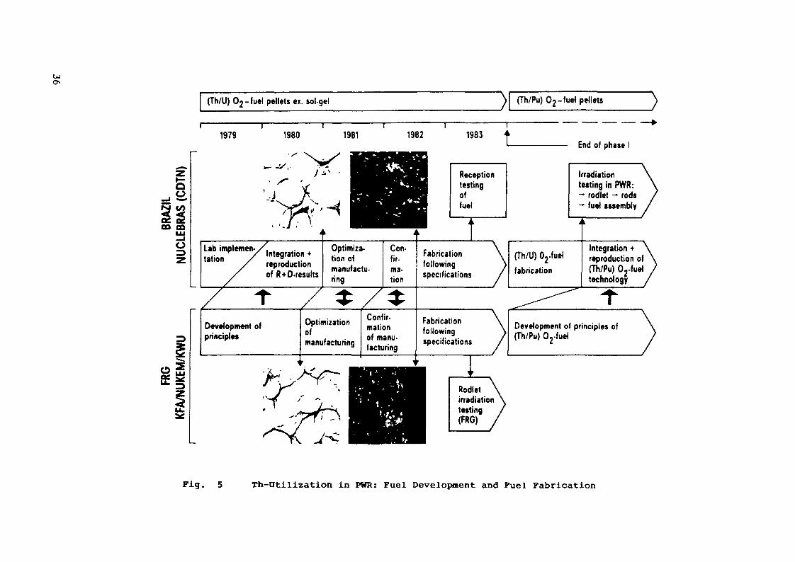
Fig. 5 Th-Otilization in PVIR: Fuel Development and Fuel Fabrication
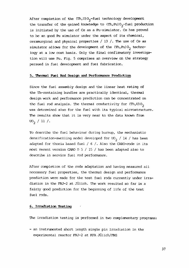
After completion of the (Th,U)0_-fuel technology developmentthe transfer of the gained knowledge to (Th/Pu)0_-fuel productionis initiated by the use of Ce as a Pu-simulator. Ce has provedto be an good Pu simulator under the aspect of its chemical,ceramurgical and physical properties / 13 /. The use of Ce assimulator allows for the development of the (Th,Pu)0_ techno-logy at a low cost basis. Only the final confirmatory investiga-tion will use Pu. Fig. 5 comprises an overview on the strategypersued in fuel development and fuel fabrication.
5. Thermal Fuel Rod Design and Performance Prediction
Since the fuel assembly design and the linear heat rating ofthe Th-containing bundles are practically identical, thermaldesign work and performance prediction can be concentrated onthe fuel rod analysis. The thermal conductivity for (Thtu)0^was determined also for the fuel with its typical microstructure.The results show that it is very near to the data known from
To describe the fuel behaviour during burnup, the mechanisticdensification-swelling model developed for UO_ / 14 / has beenadapted for thoria based fuel / 6 /. Also the CARO-code in itsmost recent version CARO D 5 / 15 / has been adapted also todescribe in service fuel rod performance.
After completion of the code adaptation and having measured allnecessary fuel properties, the thermal design and performanceprediction were made for the test fuel rods currently under irra-diation in the FRJ-2 at Jülich. The work resulted so far in afairly good prediction for the beginning of life of the testfuel rods.
6. Irradiation Testing
The irradiation testing is performed in two complementary programs:
- an instrumented short length single pin irradiation in theexperimental reactor FRJ-2 at KFA Julich/FRG
37

- a segmented fuel rod and full length fuel rod irradiation ina host FA inserted into a connercial power reactor in Brazil.
The strategy behind these two branch program is to have a fastperforming single rod irradiation, evaluating the burnup per-formance of the as-developed fuel and to generate the data baseneeded for licensing the pathfinder irradiation in the powerreactor. The pathfinder irradiation provides the performancedata under power reactor conditions. The single rods will beexamined in a detailed PIE, whereas the pathfinder fuel rodswill be inspected initially by available pool inspection techniques/ 16 /. However, pool inspection is able to indicate the existenceof any clad degradation, also from the inside, or the existenceof defects if there are any. Thus, the results from both testseries provide a reliable data base to assess the burnup perfor-mance of fuel pins with (Th,U)0_ under power reactor conditions.
Table 3 gives an overlook on the single rod irradiation programand its actual status. The defect in the test LV 9.6-E 62 isdue to a failure in the instrumentation.
Table 3 : Overview on FRJ-2 irradiation experimentsValues for E 61 in brackets were reachedtill 30 Sept. 84
Rig. No.
LV9.6-E60
Test fuel rod(position)
TT80 (top)
TDT81 (bottom)
Max.fro«U/c»
167
391
rod powertillWem
346
430
Bumup Irrad. ti«e
GUd/UW d
6,82 116,1
8,22
PIEco
mpl
étée
LV9.6-E61 TT82 ( top) 111 234 8,2
enen0}t-to>o
TDT83
LV9.6-E62 TT84
TDT85
(bottom)
(top)
(bottom)
278 308 10.0
112 235 1,5 *
276 300 1,26*
0.
176 5
34 Suen0t-,CLcH
* terminated after a defectin the instrumentation
38

Table 4 summarizes the pathfinder irradiation program. In orderto investigate the operational behaviour and the dimensionalstability of the fuel at different temperatures, the clearancesbetween the fuel pellet and the cladding shall be varied withinthe full tolerance scale, i.e. in the range of 120 to 220 urn,in the segmented rods. Thereby first priority shall be givento the medium clearance of 170 urn. A full-length rod shall beirradiated to show the operational performance of a standardfuel rod with that type of thoria fuel.
To get information on the fuel performance in the whole burn-up range to 45 GWd/kg HM segmented fuel rods shall be irradiatedfor 1 to 4 operational cycles. This means, one segmented fuelrod shall always be un-loaded during the refueling shutdownsof the power plant. The full-length fuel rod shall be irradiatedfor altogether 4 operational cycles and finally be examined inthe spent fuel pond of the power plant. Intermediate examinationsare planned to be performed during each refueling shutdown ifthe time schedule for the refueling allows.
7. Investigation on the back end of the fuel cycle
For the most interesting case - the use of LWR recycling Pu asfissile material in Th fuel - worth mentioning savings are alreadyachieved in the once through-put away cycle. Thus no reprocessingis needed for this fuel. But the long term storage of spent thoriafuel has to be still considered. Preferentially dry storage techni-ques will be used. Based on the excellent experience on the drystorage of spent UO containing LWR-fuel / 17 /, no major problemsshould arise in this field. Only the different decay heats from(Th,Pu)0_, in comparison to the UCL fuel, require an assessmentat which periods after shut down dry storage may start in bothversions: unconsolidated or consolidated manner. The problemareas of final disposal have not yet been addressed.
Using HEU as fissile material reprocessing is needed to achieveresource conservation (U- ore savings) and savings in the fuel
39
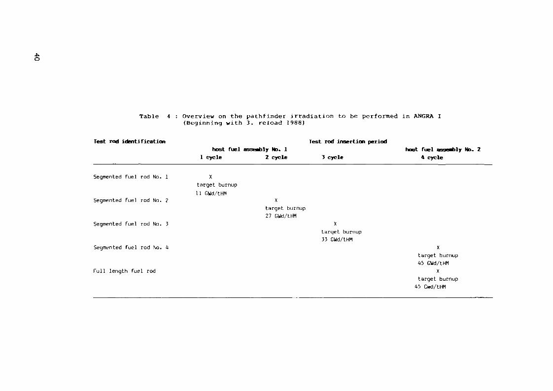
Table 4 : Overview on the pathfinder irradiation to be performed in ANGRA I(Beginning with 3. reload 1988)
Test rod identificationhost fuel assembly No. 1
1 cycle 2 cycle
Test rod insertion period
3 cyclehost fuel assembly No. 2
4 cycle
Segmented fuel rod No. 1
Segmented fuel rod No. 2
Segmented fuel rod No. 3
Segmented fuel rod No. 4
Full length fuel rod
target burnup11 GWd/tHM
target burnup27 GWd/tHM
target burnup33 GWd/tHM
target burnup45 GWd/tHM
Xtarget burnup
45 Gwd/tHM
cycle cost. A scoping study on reprocessing showed the followingresults:
Cold dissolution experiments have shown that in the dissolutionof (Th,U)0_ fuels by Thorex solution, the Zircaloy clad is alsodissolved to some extent and, besides this the dissolution timeis 30 % increased if Zircaloy cladding is present. Nevertheless,final statements about dissolution behaviour of fuel with highburn up can only be made after hot experiments / 6 /. Those ex-periments are in progress.
For an optimization of the solvent extraction processes, distri-bution data covering the whole range of interest have been eva-luated. Interpolations and extrapolations are possible by a com-puter program. Considerations about the readioactivity of repro-cessed U-233 fuel from power reactors on the one side and theexperience gained so far with the THOREX process variants onthe other side lead to the proposal of a single-cycle THOREXprocess / 6 /.
8. Conclusions
The major results of the program work, confirmed in all relatedworking areas, can be summarized so far:
- The standard EWR may use (Th,U)02~fuel and even (Th,Pu)O_ fuelwithout any changes within the reactor system, within the coreor in the fuel assembly design.
- Nearly the same performance of the reactor can be expectedusing (Th,U)02~fuel or (Th/Pu)0_ as for of IXL-fuel in a stan-dard ïVJR nearly
- (Th,U)0_-fuel can be easily manufactured within the same speci-fication limits used for U0~-fuel. A slightly modified ex-gelprocess from the HTR-technology as a chemical conversion iscombined with the standard pelletizing, sintering and grindingprocess which is in commercial use for LWR-fuel fabrication.The development of (Th,Pu)02 fuel by means of Ce as simulatormaterial is in good progress.
41
- Thermal and mechanical design of fuel rods containing thoria-based fuel can be done as well as with standard U0_ fuel pins.The performance predictions made for the irradiation testshave been validated so far by the irradiation results.
- A favourable strategy to avoid the need of early reprocessingand to strive for worthmentioning savings in U-ore might bethe use of (Th,Pu)CL fuel in a "once through-put away cycle"with extended burnups. Problems encountered with long termstorage of spent Thoria-based fuel are very similar to thatknown frctn urania-fuel. It should not pose any extra problems.
- Thoria fuel may in the HEU-cycle require reprocessing to realizesubstantial savings in fuel cycle costs. Reprocessing of spentLWR-fuel with (Th,U)0«-fuel is principally feasible using repro-cessing schemes derived form experience gained in the contextwith HTR work and in combination with a chop-leach techniqueusing the Thorex solvent.
References
/ 1 / Carneiro, F.A.N., Andrade, E.P., Schlosser, G.,"Brazilian-German Investigations of Th-Utilization in KWU-Type PWR's - Result of Nuclear Core Design"IAEA Technical Committee in Advanced Light and Heavy WaterReactor Technology, Vienna/Austria, 26-29 Nov. 84
/ 2 / Rahmenvertrag über Zusammenarbeit in der wissenschaftlichenForschung und technologischen Entwicklung zwischen denRegierungen der Bundesrepublik Deutschland und der Födera-tiven Republik Brasilien vom 09.06.1969
/ 3 / Memorandum of Understanding between KFA and NUCLEBRAS onCooperation in the Field of High Temperature Reactors andGas Cooled Fast Breeder Reactors and the Thorium Cyclein High Temperature Reactors and the Water Reactors aswell as in Gas Cooled Fast Breeder Reactors, March 8, 1978
/ 4 / Special Agreement between KFA Jiilich and NUCLEBRAS on aProgram of Research and Development on the Utilizationof Thorium in Pressurized Water Reactors,March 5 and 20, 1979
/ 5 / Maly, V., Pinheiro, R.B.,"Technology Transfer within the KFA/NUCT.ERRAS CooperativeProgram Th-Utilization in PWR's"ICONT III Conf. Oct. 85, Madrid/Spain
42
/ 6 / "Program of Research and Development on the Thorium-Utili-zation in PWR's" Final Report for Phase A, 1979-1983, May1984 Jul. Spez. 266 ISSN 0343-7639-NB/CDTN-471/84-KWUB 22/84/35-NUKEM F u.E. 83075
111 Porsch, D., Andrade, E.P., Schlosser, G.,"Deutsch-Brasilianische Studie zur nuklearen Auslegungvon PWR mit Th-Brennstoff", Jahrestagung Kerntechnik, München1985
/ 8 / Huschka, H., et. al."Coated Fuel Particles, Requirements and Status of Fabri-cation Technology"Nucl. Technol., 35, 238 (1977)
/ 9 / Aßmann, H., Becker, M.,"Technology of UO„-Fuel Fabrication by the AUC Powder Pro-cess" i
Trans. Am Nucl. See. 31, 147-148 (1979)/ 10 /Aßmann, H., Peehs, M., Dörr, W.,
"Oxide Fuel with Controlled Microstructure"J. Am. Cer. Soc., Vol. 67, 631-636, Nov. 9, 1984
/ 11 /Peehs, M., Dörr, W., Hrovat, M.,"Development of a Pelletized (Th,U)O?-Fuel for LWR-Appli-cation", IAEA Advisory Group Meeting on Advanced Fuel Tech-nology and Performance, Würenlingen/Switzerland,Dec. 1984
/ 12 /Cardoso, P.E., et al.,"Development of Alternative Fuel for PWR" III CongressoBrasileiro de Energia, Rio de Janeiro , Oct. 1984
/ 13 /Dörr, W., Hellmann, S., Mages, G.,"Study of the Formation of UO?-PuO~ Solid Solution by Meansof U02-CeO2 Simulates"13. Int. Cof. Science of Ceramics, Spet. 85,Orleans/France
/ 14 /Aßmann, H., Stehle, H., "Thermal and In-Reactor Densifca-tion of UO_. Mechanisms and Experimental Results", Nucl.,Eng. Design, Vol. 48, No. 1, June 1978
/ 15 /Eberle, R., Wunderlich, F., Distler, I.,"The KWU Fuel Rod Code CARO", IAEA Spec. Meeting on FuelElement Performance Computer Modelling Blackpool, March1978
/ 16 /Knaab, H., Knecht, K., Garzarolli, F.,"KWU Nuclear Fuel Service", Kerntechnik, 14. Jhg. (1977),No. 3, p. 122
/ 17 /Peehs, M., Fleisch, J., "LWR Spent Fuel Storage Behaviour"J. Nucl. Mat., to be published.
43
THORIUM CYCLE IN UNMODIFIED PWRs
G. GAMBIER, H. SCHAEFFERDirection des études et recherches,Electricité de France,Clamait, France
Abstract
For more than ten years the Commissa r i a t à L'Energie Atomique and théElec t r i c i té de France have jointly carr ied out experimental and design studies indi f ferent f ie lds : HTRs, MSRs, PWRs.
W i t h regard to the P W R s , the s tud ies f i r s t concerned the use o fP lu ton ium w i t h T h o r i u m to s t a r t the cyc le . A s a t i s f a c t o r y solut ion has beenobtained by recycl ing the Plutonium wi th Thorium as from the f irst core loading.The solution proposed consists of loading the whole reactor w i t h Th-Pu assembliesf rom the f i rst core and no longer using the standard checkerboard Loading ; theassembl ies are loaded in rings. Two posi t ive points appear : burnable poisons areno longer necessary and the assembl ies are no longer divided into several zones(as w i t h P lu ton ium r e c y c l e w i t h Uranium in reloadings). T h e r e a re two ra thernegat ive c h a r a c t e r i s t i c s : the second generation Plutonium may be used only inFBRs and the conve rs ion f a c t o r is ra ther smal l . N e v e r t h e l e s s the proposedsolution g ives acceptable pin power peak, temperature coeff icients, etc...
S a t i s f a c t o r y solutions have also been obtained for cores loaded wi thTh-U233 assemblies. The main problem is, in this case, the moderator temperaturec o e f f i c i e n t . D i f f e r e n t so lut ions may be found to solve th is problem : we havechosen the one which gives simultaneously'an acceptable moderator coef f ic ient anda conversat ion f ac to r improvement (the use of spectrum shif t control).
INTRODUCTION
For some years now Electr ic i té de France (EDF) has been carrying outs tud ies concern ing the Thor ium cyc le . These studies, begun in 1969 inre la t ionship to High Tempera tu re R e a c t o r s (HTR), have been per fo rmedjointly w i th the Commissar iat à L'Energie Atomique (CEA) /1/ : the NuclearStud ies Cen te r at Sac lay for theore t i ca l studies concerning designs andcodes deve lopments ; the Nuclear Center at C a d a r a c h e for the integralexper iments made necessary by the search for improvements in the accuracyof the basic nuclear data. These studies were then completed in the fieldof Molten Salt Reactors (MSR) (from 1975 on) and more recently (from 1979on) in the field of Light Water Reactors (LWR) 121 /3/.
PLUTONIUM RECYCLE UITH THORIUM IN UNMODIFIED PWRs
To start the Th-U233 cycle it is necessary to begin with a Thorium-F i s s i l e Ma te r ia l couple f r o m w h i c h the f i s s i l e e lement may be easi lyobtained. Two possibil i t ies may be considered :
The High Enriched Uranium/Thorium/11233 cyc leThe Plutonium/Thorium/U233 cycle.
45

The first case seems to be inconsistent with the present developmentof PWRs using Low Enriched Uranium. Furthermore, since important Plutoniumquantities will be available it is obvious to try to use this material tostart the Thorium cycle ; moreover the Plutonium recycle w i t h Thoriumappears as the logical continuation of the studies concerning the Plutoniumrecycle M/ /5/ and the uranium recycle /6/ 111.
The use of t h i s PUR Plutonium, containing rather important evenisotopes proportions, is of course particularly favourable in Fast BreederReactors (FBRs).. The best way to use the Plutonium is thus clearlydefined : it must be used in the LMFBRs. Nevertheless, taking into accountthe important production of Plutonium (250 kg/GWe/year in a PWR) and therather slow development of LMFBRs, it seems natural to try to find uses fort h i s element in t h e r m a l reactors w i t h Uranium or w i t h Thorium /8/. Inaddition this recycling may be considered as an attractive storage beforeuse in LMFBRs /9/ ; the quality of the Plutonium, w i t h regard to the FBRsis in fact only very little affected by the recycling /10/.
Reactor characteristicsThe PWR considered for our studies is the 920 MWe Bugey 2 reactor. In
order to introduce no other problems than the use of Thorium, we have notmodified the assemblies characteristics.
The reactor contains 157 17 x 17 fuel rod assemblies. The i n i t i a lenrichments for the three zones are respectively : 2.1% ; 2.6X ; 3.1X.
Physical characteristics of the PuOg - ThOj latticeThe moderator ratio optimum for a Th(>2 - PuO? lattice, with a PuO?/
(PuO? + Th02^ ratio equal to 7.27X (this concentration allows, atequilibrium, the same cycle length to be obtained as with the standardUranium cycle), is approximately equal to 8 (Figure 1) instead of 4 for theUranium fuel. The spectrum is particularly hard (Figure 2).
The fact of keeping the 1.92 standard moderator ratio leads to animportant Plutonium concentration.
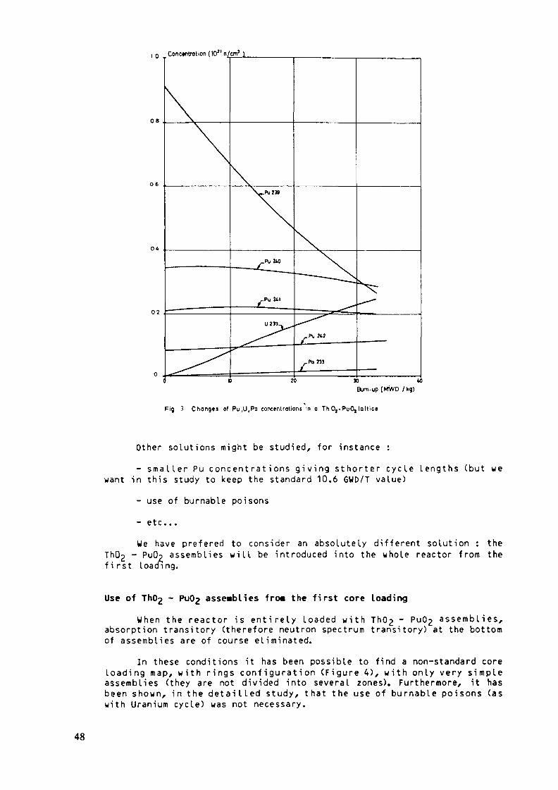
The changes in heavy nuclides concentrations as a function of theburn-up is given on figure 3.
Use of Th(>2 - Pug assemblies in the reloadings of a Uraniua core at theequi libriua
If we try to put ThU2 - PuO£ assemblies in the reloadings of areactor w h i c h is at e q u i l i b r i u m (in the standard Uranium cycle), as w i t hthe conventional Plutonium recycle for instance, important difficultiesappear.
An acceptable pin power peak has not been obtained during thetransitory cycles between the Uranium loaded core and Pu - Th loaded core.It is due to strong absorption differences beetween UO? assemblies and ThO^- PuOp assemblies. The use of assemblies divided into three zones (4% of Puin the outer zone, 6X of Pu in the intermediate zone and 9X of Pu in thecentral zone) is not sufficient to obtain an acceptable value for the pinpower peak.
46

Tk»
12
boron concentration Oppm
boron •concentration 500 pp m
roto moderator/fuel—I
10
Fig ' Multiplication factor V. ,of the Th02 -Pu 0,(727%Pu)lattice as a function o< volumetric moderator/loel ratio
5 nu« (arbitrary units)
Fig 2 Energy distribution of neutrons in the Th Oj-PuOj lattice
47
Concentration ( lO11 n/cm1 )
02
o .M 40
Bum-up (MWD /kg)
Fig 3 Changes of Pu.U.Pa concentrations in a Th 0,-PuOj latt ice
Other solutions might be studied, for instance :- smaller Pu concentrations giving sthorter cycle lengths (but we
want in this study to keep the standard 10.6 GWD/T value)- use of burnable poisons- etc...We have preferedPuOp assemblies
first loading.Th02 -
to consider an absolutely different solution : thew i l l be introduced into the whole reactor from the
Use of - Pu(>2 assemblies fro« the first core LoadingWhen the reactor is entirely loaded w i t h Th02 ~ Pu(>2 assemblies,
absorption transitory (therefore neutron spectrum transitory) at the bottomof assemblies are of course eliminated.
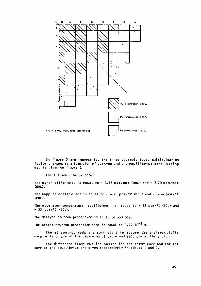
In these conditions it has been possible to find a non-standard coreloading map, w i t h rings configuration (Figure 4), w i t h only very simpleassemblies (they are not divided into several zones). Furthermore, it hasbeen shown, in the detailled study, that the use of burnable poisons (aswith Uranium cycle) was not necessary.
48
•NXi
Fig 4 T h O j - P u O j tint cor'« loading
\N
Pu concentrotion 436%
Pu conctntrotion 5 20%
Pu concentration 727%
On figure 5 are represented the three assembly types multiplicationfactor changes as a function of burn-up and the equilibrium core loadingmap is given on figure 6.
For the equilibrium core :The Boron efficiency is equal to - 3.13 pcm/ppm (BOL) and - 3.70 pcm/ppm(EOL).The Doppler coefficient is equal to - 4.45 pcm/°C (BOD and - 3.54 pcm/'C(EOL).The «oderator temperature coefficient is equal to - 36 pcm/°C (BOL) and- 53 pcm/°C (EOL).The delayed neutron proportion is equal to 330 pcm.The prompt neutron generation time is equal to 0.44 10~^ s.
The 48 control rods are sufficient to assure the antireactivitymargins (2580 pcm at the beginning of cycle and 2850 pcm at the end).
The different heavy nuclide masses for the first core and for thecore at the equilibrium are given respectively in tables 1 and 2.
49

Muplication factor km
0.9
.727%
^^ 5.20%
.«.36%
08a 10 20 » to
Bum-up (MWD/kg)
Fig 5 Infinite multiplication factor of Th 0,-Pu 0, loltices(4.36% ;5.20% ;727 %)as a function of burn-up
Fig 6 ThOj- PuC^ cort loadingat the equilibrium
(fourth cycle)
(third cycle)
(»cond cycl*)
(first cycle)
50

TABLE 1 : FIRST Pu02 - Th02 CORE INVENTORY (kg)
ISOTOPES
Th 232Pu 238Pu 239Pu 240Pu 241Pu 242
Fissile PuTotal Pu
TOTAL
Zone 14.36X53 ass.
21,96310
57121813653
707988
22,681
Zone 25.2X52 ass.
21,0981166925515963
8281,157
22,255
Zone 37.27X52 ass.
20,6401693535722387
1,1581,618
22,258
TOTAL
63,43137
2,175830518203
2,6933,763
67,194
TH02 - U233O2 ASSEMBLIES LOADED CORE
The Th02 - Pu02 reac to rs , desc r i bed in the precedent paragraph,•• •• • • 300 kg of Uranium by QVs and by year.produce, at the equil ibrium, about
The Uranium composit ion is
U233 : 92.14%U234 : 6.50%U235 : 1.06XOther isotopes : 0.30X.
This type of Uranium will be represented by U1. U'02 - Th02a s s e m b l i e s are now loaded in the surrounding zone of a Bugey-2 typereac tor , supposed to be at the equi l ibr ium in the convent ional Uraniumcyc le . I t is important to know how would such s tandard r e a c t o r s wouldopera te w i t h UT02 - Th02 fue ls because they might be used during thet ransitory period before starting specially adapted Thorium cycle reactors.It would be the same for the Th02 - Pu02 fuel r e a c t o r s : a be t te rconversion would be probably found by moderator ratio modifications.
51

TABLE 2 : Th02 ~ Pu02 CORE INVENTORY (kg) AT EQUILIBRIUM
! LOADEDISOTOPES ! ASSEMBLIES
! BOLii
Th 232 ! 20,640ii
Pa 233 1iU 233 !i
iPa 233 + U 233 !iU 232 ! -iU 234 ! -iU 235 !
iTotal U !
Pu 238 ! 16iPu 239 ! 935iPu 240 ! 357iPu 241 ! 223iPu 242 ! 87
Fissile Pu ! 1,158iTotal Pu ! 1,618
iAm 241 !iCm 242 !iAm 243 !Cm 244 !i
iTOTAL ! 22,258i
X
92.73
5.207.27
100
DISCHARGEDASSEMBLIES
EOL
20,260
20238
2571.3193
280
16284300209119
493928
1233411
21,528
X
94.10
0.091.11
1.2060 ppm0.090.01
1.30
0.071.321.390.970.55
2.294.30
0.3
100
1BALANCE !i
;i
- 380 !i+ 20 !i+ 238 !i
+ 257 !+ 1.3 !i+ 19 !i+ 3 !i
;+ 280 !i
;ji
- 651 !- 57 !i- H !
!+ 32 !i- 665 !- 690 !j
ii
+ 60 !jiii
- 730 !j
52
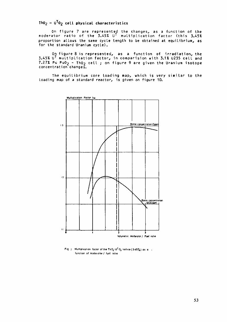
Th(>2 - U Og cell physical characteristics
On f igu re 7 arc rep resen ted the changes, as a func t ion of them o d e r a t o r rat io of the 3.45% UT mu l t i p l i ca t ion f a c t o r ( th is 3.45Xproportion al lows the same cycle length to be obtained at equilibrium, asfor the standard Uranium cycle) .
On f igure 8 is represented, as a funct ion of irradiation, the3.45X UT mu l t ip l i ca t ion fac to r , in compar is ion w i t h 3.1X U235 cel l and7.27X Pu Pu02 - Th02 cel l ; onconcentration changes.
f igure 9 are given the Uranium isotope
The equi l ibr ium core loading map, w h i c h is very s imi la r to theloading map of a standard reactor, is given on figure 10.
Multiplication Factor k*
.Boren concentrationOOQppm
J JVolumetric moderator / Fuel ratio
Fig 7 Multiplication factor of the ThO,-UT0, lattice (345%) as o .function of moderator/ fuel ratio
53

multiDlicatlon factor
12
10
0.9
\\\
\V* 'V\ \N:"^,x*«v
'̂"^V̂>xxN
_______ TbOj.U'Oj t.KV.
_ _ _ _ _ T h O
__ _ __ UO,
s>>.̂xV "-^_^ss. "--^
XT
.puo, 7.n%î.1%
**%. ^s^ "̂ >.̂
^x^^ "
\7
burn.up(MWCVkg)
10
o n NFig g Multiplication factor of Th C^-UTOj ,ThOj-Pu C^.UOj laltices os a function of
burn-up
concKittotion ( 10 n /cm)
075
050.uni
02Î
005
K 40burn-up(MWD/kg)
Fig 9 Changes of U,Pa concentrations in th«ThOj-UT02 laltic»
54

10
(fourth cycle)
(third cycle)
(stcond cycli)
(first cycl«)
Fig 10 Th 0,-UTOjCOr« loodinçot Ih« »quilibnum
For the core, at equilibrium :
The Boron e f f i c i e n c y is equal to - 7.53 pcm/ppm (BOD and - 9.76 pcm/ppm(EOL).
The Doppler coef f i c ien t is equal to - 2.9 pcm/°C (BOL) and - 2.63 pcm/°C(EOL).
The moderator temperature coeff ic ient is equal to + 15 pcm/ 'C (BOL) and- 8 p c m / ° C (EOL).
The delayed neutrons proportion is equal to 315 pcm.
The prompt neutron generation time is equal to 1.5 10"-* s.
The 48 cont ro l rods are su f f i c i en t to assure the an t i r eac t i v i t ymargins (6580 pcm at the begining of cyc le and 6900 pcm at the end).
Reactor inventory
The core inventory is given in table 3.
A very important conversion improvement may be obtained by using theSpectrum Shift Technique. In this case, the positive moderator temperaturec o e f f i c i e n t at the beginning of the c y c l e is e l iminated and the meanconversion ratio reaches 0.87 instead of 0.64 w i th a light water moderator(f igure 11).
55

TABLE 3 : UT02 - Th02 CORE INNVENTORY (kg), AT EQUILIBRIUM
ISOTOPES
Th 232
Pa 233U 233
Pa 233 4 U 233U 232U 234U 235U236
Total U
TOTAL
LOADEDASSEMBLIES
BOL
21,486
706
7063.1.
51.570.3
768
22,254
. , _. ———%
96.55
3.18
3.180.0140.240.3
3.45
100
DISCHARGEDASSEMBLIES
HOL
20.890
31415
4461.8
116254.5
593
21,482
1 ' i" -•— ' ——X ! BALANCEi
ii
97.23 ! - 596;! 4 31
2.08 !! - 291i
2.08 ! - 26084 10~6 ! - 1.3i0.54 ! + 64.5i0.12 ! 4 18i0.02 ! 4 4.2
2.76 ! - 175iI
100 ! - 768i
conversion factor
10
\
Qfl\
\Cycl* Z Cycl* 3
MOO 0000 15000 20000 »000 30000 39000t>urn-up<MWO/lq)
Fig n ThO,-UTOj(SSCR)conv«rsion factor as a fuoctionof burn-up forth» first thr«» cycl«*
56

CONCLUSION
The solution proposed to start the th-U233 cycle in unmodified PWRsconsists of loading the whole reactor with Th-Pu assemblies from the firstcore and no longer using the standard cherkerboard loading ; the threeassembly types (3 Pu concentrations) are loaded in rings.
The U233 being obtained, its best use is in Spectrum Shift ControlReactor (SSCR). This system gives simultaneously an acceptable moderatorcoefficient and a good conversion factor.
The Th-l)233 in unmodified PWRs does not give large improvements withregard to uranium consumption (comparated to conventionnal plutonium anduranium recycle). Its main objective is to open the way of the thoriuncycle in reactors ; the "royal way" being probatly the Molten SaltReactors.
REFERENCES
IM D. GRENECHE, "Review of French Studies on Fuel Cycles for HTR and MSRIncluding Nuclear Data Evaluation", Japan - US Seminar on Thorium FuelReactor, Nara, Japan, October 18 - 22, 1982.
121 H. S C H A E F F E R , "Etude du c y c l e T h o r i u m dans les réacteurs à eaupressurisée", Thèse de 3ème cycle Orsay 1979, 1981.
/3/ G. GAMBIER, "Thorium Cycle in PWRs : Alternative To a Slow Penetration ofFBRs", Japan - US Seminar on Thorium Fuel Reactor, Nara, Japan, October 18- 22, 1982.
/4/ G. GAMBIER, C. GOLINELLI, "PWR Fuel Cycle Evaluations : CEA - EDFExperimental Program", Proc. ANS Topical Meeting on Technical Bases forNuclear Fuel Cycle Policy, Newport, U.S.A., September 21 - 24, 1981,p. 7.2-1.
/5/ J. BERGERON, J. BOUCHARD, M. DARROUZET, and G. GAMBIER, "CEA - EDF Studieson Plutonium Recycle in Light Water Reactors", Trans. Am - Nucl. Soc., 31,287 (1979).
/6/ M. DARROUZET, R. GIRIEUD, C; GOLINELLI, and P. SALMON, "Recycling of theReprocessed Uranium in PWRs", Trans. Am. Nucl. Soc., 40, 165 (1982).
Ill M. DARROUZET, A. SIMON, and M. SOLDEVILA, "Uranium Recycle in PWRs",Topical Meeting on Advances in Reactor Physics and Core Thermal Hydraulics,Kiamesha Lake, USA, September 22 - 24, 1982.
/8/ G. GAMBIER, "The Different Ways of Using Plutonium in PWRs", Trans. Am.Nucl. Soc., 34, 385 (1980).
57

/9/ G. GAMBIER, "Plutonium R e c y c l i n g in L W R s : A S t o r a g e Be fo re Use inBreeders", Trans. Am. Nucl. Soc., 33, 407 (1979).
/10/ G. GAMBIER, J.M. GOMIT, and J.P. PERRUTEL, "Utilisation dans les réacteursà neutrons rapides de Plutonium reyclé dans les réacteurs à eau ordinaire",Proc. of the International Symposium on Phys ics of Fast Reactors, Aix-en-Provence, France, IAEA-SM-2U/K (1979).
58

THORIUM UTILIZATION IN SOLVINGTHE NUCLEAR POWER FUEL PROBLEM
I.S. SLESAREV, A.G. MOROZOV, D.F. TSURIKOVI.V. Kurchatov Institute of Atomic Energy,Moscow, Union of Soviet Socialist Repulbics
Abstract
The future large nuclear energy appears to be a many-bran-ched industry. Creation of such an industry and dimensions ofits beneficial influence on the development of industrial pro-duction depends to a great extent on the capability to generaterelatively low-priced fuel on the basis of commercial nuclearbreeding. So far no universal approach has been available foraolving the nuclear fuel problem, though some realistic and ef-fective ways to case its ocuteness have been developed. The mostradical means for solving the fuel problem is application offast breeder reactors in combination with improved fuel utiliza-tion characteristics of the thermal reactors. Among the ways re-alizing the improved fuel balance in the thermal reactors empha-sis should be placed on use of the Uranium-233 - Thorium cycle.The available estimates of fuel utilization by the thermal reac-tors on U/Th cycle are indicative of its attractiveness. The pa-per considers a method for Uranium buildup in the blankets ofcurrent fast reactors, required for transition to the ïïranium-233 - Thorium cycle in the thermal systems. It is shown thatthorium utilization contributes noticeably to the nuclear fuelresources. Combination of the Uranium-Plutonium and Thoriumcycles ensures long-term fuel supply, makes the nuclear energyproduction more flexible and, at realistic requirements to thelevel of fast reactor breeding, enables the self-provisionregime to be realized in future.
59

Successful development of the world nuclear power produc-tion (NT) and, primarily, nuclear electrical energy production,is probing its capability to contribute essentially to theoverall energy production system. The developed nuclear energyproduction opens a wide possibility of using the nuclear energyin various technological processes, in heat production forindustrial and district heating.
The future large NP is thought as a many-branched industryand its creation depends on the capabilities of providing itwith relatively inexpensive fuel first with Uranium-235 and thenwith recycled fuel, plutonium and Uranium-233 on the basis ofcommercial breeding. Taking into account the scale of energyrequirement, the organization of fuel breeding is an indispen-sable condition, though at the current stage of NP developmentwhen the Uranium-235 resources are still large and the overallenergy production by existing nuclear power stations is rela-tively low, the role of breeding is unjustifably underestimated.
It may be expected that deficiency of natural uranium re-sources would become noticeable in the NP economy by the endof this and beginning of the next century. By that time themeasures for sharp reduction of natural uranium utilization willhave to be developed and their realization begun.
By present some real methods for easing the NP fuel problemhave been worked out. One of them is connected with improvementof the fuel cycle of the thermal reactors and reprocessing ofspent fuel enabling the natural uranium requirement to be redu-ced by 20-30$ (see Table 1). An additional and very essentialbenefit may be got from the measures directed to increasethe breeding ratio in the thermal reactors by use of dense fuel(e.g. uranium suicides), dense fuel lattices (APWR-type re-actors) etc. However, the radical solution of the NP fuel prob-
60

Table I. Specific natural uranium utilizationin loading feeding and separative works Efor the WER-1000 reactors with uranium-233 and235 (direct replacement)
gqEgEq
kg/MÏÏ(e)kg/MWkg/MWkg/MW. y ear
VYER-1 OOOopen cycle
460230250140
W3R-1000closed cycle
250140180100
WER-1000U-233-Th
1106010050
lern lies in breeding, the fast reactors operating on the ura-nium-plutonium cycle being the most available breeding scheme.The requirements to be imposed on the breeder reactors willchange in the course of the NP development. At present, when thenuclear fuel is still relatively inexpensive, the main effortsmust be directed to restrain the rate of the energy productioncost. Today the problem of maximum excess fuel production is notstill acute, but of great importance are the non-fuel cost com-ponents such as investment (capital) costs. In the future theefforst will inevitably shift to improvement of the breeding gain.
The recent studies of the methods for improving the fastsodium reactor breeding, including development of the heteroge-neous oxide metalic core concept, have revealed a real possibi-lity for increasing the breeding ratio up to 1.55-1*6 /2/.However even at so high characteristics the self-provision fuelcycle may be only realized when the fast reactor fraction inHP were significant, no lower than 60$. ?or the many-componentenergy production structure the requirement for such a highfast reactor fraction may prove to be too stringent.
61

The fuel problem might be helped by use of the uranium-plutonium cycle in combination with the uranium-thorium mode,which allows a significant reduction in fuel requirement forthe thermal reactors feeding. Here important is not utilizationof thorium as fuel but the better nuclear and physical charac-teristics of uranium-233 in the thermal reactor spectrum. As aresult the net production of secondary fuel determined by thebreeding gain (BG) increases from - 0.5-0.6 to - 0.2 - 0.3 inthe light water reactors with the oxide uranium-thorium fuelat high burnups, though the fast neutron fission fraction re-duces sharply because of the low thorium fission cross section.
Transition to dense fuel (e.g., metallic thorium) is lesseffective than in the case of the uranium fuel. However at re-latively low burnups this transition may permit the fuel requi-rement for fuel feeding to be practically eliminated (Table 2).
Table 2. Characteristics of thermal reactorswith U-235-Th cycle (fuel delay time-3 years)
Natural uranium requirement Separative work requirement
WERRBMKHIGH
loadingt /GW(e) 10~3
0.61.20.4
feedingt/GV/(e)JO~3
0.250.350.17
loading
0.61.20.35
feeding
0.250.360.13
Even greater effect is reached when the thorium fuel cycleis used in the high-temperature thermal reactors (HTGR) prima-rily designed for technological purposes /3/. For example, inthe linear development of two-component energy production struc-
62
ture involving advanced faat sodium reactors and HTGRs with ura-nium-233 and with the capabilities increased at a rate of 20-30GW(e) per year, the fuel self-provision is reached after theamount of uranium-235 contained in 2-2.5 mln tons of naturaluranium and about 0.2 mln tons of thorium at a maximum thorium
4.output not exceeding 10 tons per year have been spent.Introduction of the uranium-thorium fuel cycle for the
thermal reactors is associated with a number of complicated pro-blems which are to be solved:
- the thorium-uranium reactors use a highly-enricheduranium for startup and increased amounts of uranium and largequantity of separative work at the first operation stage whilethe rejection of the reactor feeding leads to reduction of fuelburnup and to growth of fuel reprocessing.
If a part of the thermal reactors are used in the uranium_233 production mode for the rest of the reactors, then in theexponential growth of the NT capabilities at doubling timesof 20 and 15 years the natural uranium requirement over 30 yearswill not exeeed 1—2 mln tons and 2-3 mln tons, respectively.Thus NP development on the basis of the thermal reactors ope-
235 233rating on J U- Th and -'-'U-Th cycles leads to noticeable reduc-tion of the natural uranium requirement as compared to the openuranium cycle though these requirements remain still very high.However use of this cycle makes it impossible to organize theself-provision mode and this is its major disadvantage,
- commercialization of remote reprocessing of the uranium-thorium fuel at a sufficient burnup is required.
The current state of the reactor and fuel cycle facilitydevelopment as well as the fuel problem timing suggest the fol-lowing logics in the development and combining of the uranium-plutonium and uranium-thorium cycles for NP.
63
The NP development began with the thermal uranium-fuelledreactors. Transition to the uranium-plutonium closed cycle, de-velopment of spent fuel regeneration, plutonium accumulationpaves the way for rapid inroduction of fast reactors whichare to be the basis of future nuclear fuel breeding. The acute-ness of the NP fuel problem can be then eased additionally bytransition of the thermal reactors to utilization of the uranium-233 accumulated in the fast breeder reactor blankets. This way ofuranium-233 production is beneficial for the following reasons:
- the above mentioned problem of enhanced uranium-235 ex-panses for initial buildup of uranium-233 in the thermal reactorsis eliminated;
- uranium-233 losses because of parasitic radiation captureby protactinium-233 are minimized;
- remote technology of reprocessing and fabrication of theuranium-thorium fuel, developed for uranium-plutonium cycle canbe extensively used. Investigations shows general similarity oftechnological processes for both types of fuel.
The current assessments of uranium-233 buildup in the tho-rium blankets of advanced fast sodium reactors with improvedbreeding (heterogeneous reactor core concept) indicate that re-placement of uranium-233 with thorium in the sodium breeder re-actor blankets enables uranium-233 to be produced in amounts sligh-tly (by 5%} lesser than the plutonium output in the uranium blan-kets. Replacement of the uranium blankets with thorium ones slight-ly affects also the core physical characteristics: the inner bre-eding ratio decreases by 1-2$, and the specific fuel load inc-reases by about 1-2%.
Use of thorium in the blanket, the region of lower neutronflux, permits hazardous effect of protactinium on the neutronbalance and reactor control to be reduced. The effect of the pro-
64

tactinium poisoning in the fast reactor blankets is by an orderof magnitude lower than in the thermal reactor ones.
Prom the joint of view of effective introduction of thoriumto NP, of interest are also fast reactors with mixed fuel cycle.The main fissile nuclides in this cycle are uranium-233, urani-nium-235 and in the blankets-thorium. The sodium fast reactorswith mixed fuel have the following advantages:
- smaller initial loading in comparison to the plutoniumreactor and breeder reactor on U-233-Th;
- integrated breeding ratio close to the plutonium one andnoticeably higher than that for the uranium-233-thorium fuel;
- better sodium void reactivity effect with the uranium-233fuel located in the central part of the core and plutonium - inthe periphery, the power distribution profile noticeably stabi-lized, the specific fuel load and the doubling time reduce.
The analysis of the HP fuel cycles reveals that use ofthorium contributes appreciably to the NP fuel resources. Combi-nation of the uranium-plutonium and uranium-thorium cycles ensu-res long-term fuel supply with moderate amount of thorium mi n-ing,makes NP more flexible, eases the fuel problem significantlyand for long time, with real requirements to breeding in the fastreactors and balanced structure of NP, enables the fuel self-provision mode to be realized. Introduction of thorium to nuc-lear energy production is most beneficial through uranium-233production in the breeder-reactor blankets after technology ofthe closed uranium-plutonium fuel cycle is mastered.
REFERENCES
1. A.S.Kochenov, I.K.Levina, L.I.Kovalenko: Possible waysof improvement of fuel cycles in nuclear energy production.In sb.Voprosy atomnoi nauki i tehniki, N 5(27) 1982 (in Russian).
65

2. V.V.Orlov, I.S.Slesarev, S.A.Subbotin et al. - Breedingin fast reactors with mixed oxide-metal fuel. Ill InternationalSymposium on fast reactor physics, p.244-77, Ex-an-Province,France, IAEA, 1971.
3. A.N.Protsenko. Prospects for using thorium fuel cyclesin nuclear energy production. Atomnaya tehn. za rubezhom,1978, IT 1, p.3.
4. V.M.Murogov, M.P.Troyanov, A.N.Shmelev. - Use of tho-rium in nuclear reactors. M.Energoizdat, 1983.
66

BASIC RESEARCH ON UTILIZATIONOF THORIUM-BASED NUCLEAR FUEL
J.H. ZHANG, B.R. BAO, Y.X. XIA,G.Q. WANG, J.B. ZHUShanghai Institute of Nuclear Research,Academia Sinica,Shanghai, China
Abstract
The dependences of build-up of U-233, U-232, Pa-233 andfission products on integral neutron flux for ThO^ samplesirradiated in high flux ETR at constant neutron fluxand steady spectrum have been investigated. From theseexperiments, we have accumulated experiences on furtherresearch for the behaviours of the irradited ThO» underdifferent irradiation conditions in reactor.
1)Introduction
It has been well known that thorium is not a nuclearfission fuel, but it could be transformed into U-233fan actual fission fuel with good nuclear properties,by capturing a slow neutron. Before thorium-based nuclearfuel could be used in reator, a full understanding ofthe build-up of related nuclides in reactor (mainlyU-233, U-232, Pa-233 and fission products) is veryimportant. In order to clarify the characteristicsof the build-up of these nuclides in reator, we haveinitiated a program to study the accumulations ofU-233, U-232, Pa-233 and fission products in Th02 indifferent irradiation conditions, including differentintegral thermal neutron fluxs and diffenrent neutronspectra in reactor. In this work, the dependences ofbuild-up of U-233, U-232, Pa-233 and fission productson integral thermal neutron fluxs for ThO-, samplesin high flux ETR at constant neutron spectrum havebeen investigated.
67

2) ExperimentalNuclear reactorIrradiation was carried out in high flux ETR in SouthwestChina. The reactor has thermal power of 125 MW. Maximum thermalneutron flux is 6.2ÜO ^n/cm .s and fast neutron flux is5.7.10llfn/cm2*s. It was built in 1981.Target preparations and irradiation conditionsThOp(50mg) was pressed into discal tablet of /+ mm.diameterand loaded it into a container. Then all containers wereput into irradiation tube.(figure1) Six samples were placedin two irradiation tubes.(figure2) Two tubes were put inBe-reflecting layer. Mean thermal neutron flux was 2x10 ^n/cm ,B. in this area. Six samples could receive differentthermal neutron flux, because thermal neutron flux distributionfrom the bottom to the top were not uniform as we couldsee in fig.3«(maximum non-homogenuous distribution coefficientwas 1.1+) 0. T and Q., were irradiated by one and three runsrespectively. We supposed that fast/thermal neutron fluxratio was 1.03 for two irradiation tubes. Integral thermal
PO PI Pneutron fluxs were 2x10 to 2x10 n/cm .
cutting mark
Th02 tablet
Fig.1. Irradiation container
1. External cylinder. 2. cap of external cylinder.3. Cap of internal cylinder, k- INternal cylinder.
68

top
Q13 Qi<tbottom
Fig. 2. Irradiation positions of samples in reator.
0 200- 1+00 600 800 1000mm,distance from bottom
Fig.3 Axial distribution of neutron flux in reator.
69

Radiochemical separation and determinationsAfter irradiation and "cooling", ThOp samples were dissoledinto HC1 solutions, from which yields of Pa-233 and fissionproducts could be determind by Ge(L i ) r detector. Then thesolution was adjusted into 8N HC1 and feeded on an anionexchanger ZerolitFF(Cl form,50-60 mesh) . After eluting outTh, Pa-233 and fission products from the column, U waseluted by 0.05 HNCU. U-232/U-233 ratio was determined byot-spectrometry and total U amount was determined by Asenazo-3 photospectrometric method in U solution.
3) Results and discussionsTHe results could be seen in table land also by fig.4,5,and 6. From fig.4 it shows that U-233 yields increase withincreases of integral thermal neutron fluxs. U-233 in thoriumcould reach 1.5% when integral thermal neutron flux reachs
21 22x10 n/cm . According to theoretical calcalution, U-233could reach a saturation value at about 2x10 n/cm * °we are planing to work at higher integral thermal neutronfluxs to see if U-233 reach a saturation.
Table 1. Correlations between U-233, U-232/U-233, Pa-233Cs-137, Zr-95 and integral thermal neutron fluxs.
sanple232Tb
en233U
2?5Uy252U,233ft
1J7C<
^1r
. 1020 ator.s
10 neutron/
1017 atoms
'252Th 10~3
/233u 10-5
17i 10 atoms
3 10 ^ atoms
10 atoms
1
3
3
2
2
2
4
0
1
.500
.499
.409
.33
.0
.450
.066
.3367
1
4
4
31
3
6
0
2
.4-76
.543
.771
.23
.7
.284
.522
.5316
1
5
6
4
2
4
1
0
3
.499
.040
.156
.10
.2
.215
1.77
.9554
4
1.491
12.35
15.81
10.6
8.6
5.878
173.9
11.27
5
U 466
15.91
17.83
12.0
7.5
6.998
295.6
17.82
6
1.
17
21
14
10
*81
.59
.99
.8
.0
7.672
41
25
6.4
.27
All data vere extrapolated to the end of irradiation
70
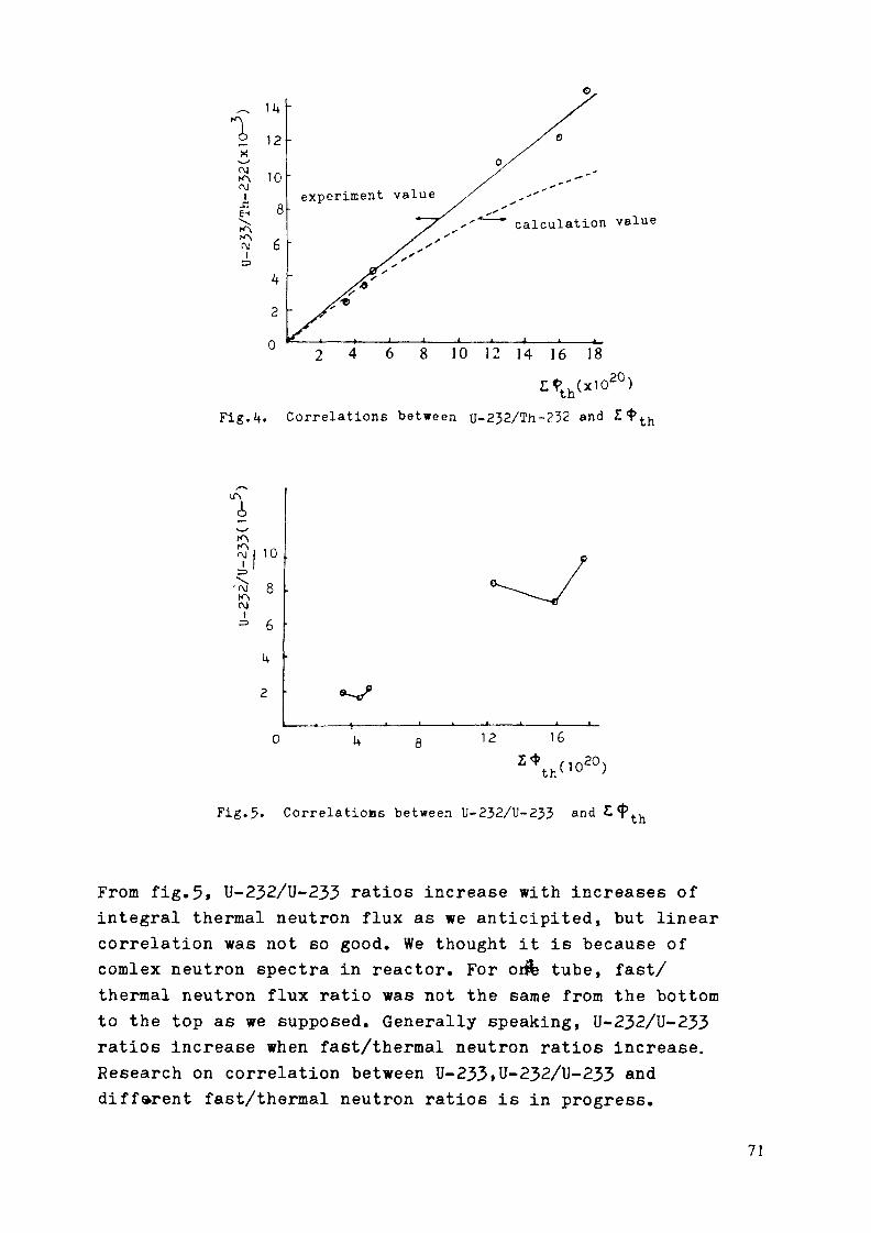
11+2 12x
CM
iC3
10
4
2
0
experiment valuecalculation value
2 4 6 8 10 12 14 16 18
Fig.4. Correlations between U-2J2/Th-232 and £$ t h
501 10'£ 8
=• 6
U
2
0 12 16
Fig.5. Correlations between U-232/U-233 and th
From fig.5» U-232/U-233 ratios increase with increases ofintegral thermal neutron flux as we anticipited, but linearcorrelation was not so good. We thought it is because ofcomlex neutron spectra in reactor. For oiife tube, fast/thermal neutron flux ratio was not the same from the bottomto the top as we supposed. Generally speaking, U-232/U-233ratios increase when fast/thermal neutron ratios increase.Research on correlation between U-233»U-232/U-233 anddifferent fast/thermal neutron ratios is in progress.
71

1000
VM
Xo
Fig.6. Correlations between Pa-233, Zr-95, Cs-137 and £ th
It is necessary to do some tests in small reactor beforewe use thorium-based nuclear fuel in large reactor. So azero power reactor(3$ enriched UO- as fuel, light wateras moderator) in our institute will be partly loaded withThOp fuel rods instead of UOp fuel rods to observe theinfluence on reactor performances.
There are still a lot of work on basic research about theutilization of thorium-based fuel left to be done. We shouldbe continuing our work in this area and accumulate necessaryexperimental data. Thereby, thorium will put into large scaleuse in near future and play an appropriate role in nuclearpower development.
72

THORIUM OXIDE BLANKET FABRICATIONFOR INDIAN FAST BREEDER TEST REACTOR
P. BALAKRISHNA, B.P. VARMA, R. RAJENDRAN,K. BALARAMAMOORTHYDepartment of Atomic Energy,Nuclear Fuel Complex,Hyderabad, India
Abstract
For an effective utilisation of Thorium in FBRs, use offertile blanket of thorium oxide/thorium mast be considered.Development of a reliable and economic fabrication techniqueof this fertile material, thus is an important step in the ultimategoal of utilization of thorium in FBRs.
Fabrication and supply of blanket assemblies containingthorium oxide pellets to the requisite quality, for full core ofIndian Fast Breeder Test Reactor, is one of the important tasksof Nuclear Fuel Complex at Hyderabad, a unit of the Departmentof Atomic Energy.
Starting with ThO„-powder obtained by oxalate precipitationand calcination, green pellets are produced through powder metallur-gical route. In order to achieve sintered densities more than 94%T.D., addition of M g in small quantities, during oxalate precipitationstage, have been found quite effective.
The effect of compacting pressure, green density and sinter-ing temperature on final sintered density of peüets and percentageof shrinkage have been studied to arrive at the optimum fabricationparameters, to yield high density in pellets requiring minimumamount of grinding.
The compactability and sinterabuity characteristics seemto be affected by long storage of powder. Ball milling of powderbefore pre-compaction and granulation almost restore the originalcharacteristics of the powder.
The paper deals with the Indian experience on fabricationof thoria pellets for the Fast Breeder Test Reactor, with some
73

emphasis on the work carried out for standardization of the para-meters, quality characteristics of the pellets and on blanket assem-blies made.
Performance test of these assemblies under actual operatingconditions of FBTR, followed by reprocessing studies, will beof great value for the Indian programme of utilization of thoriumin the envisaged FBR's.
L INTRODUCTION
With continued increasing demand on uranium andits known limited reserves, there is a growing realizationfor the need to utilise thorium to broaden the resourcebase of supply of fissionable materials.
Various concepts including LWRs, Canadian PHWRs,FBRs, and symbiotic reactor systems like HTR-FBR havebeen studied [1] [2] [3] for utilisation of thorium.
For India which has rather limited known reservesof uranium and a vast reserve of thorium, its special interestin utilization of thorium in its reactors is obvious.
Studies elsewhere [4] as well as our own [5] have shownthat thorium in radial blanket region of FBRs has only margi-nal neutron economic penalty compared to complete uraniumcycles. With this in view, it was decided to fabricate assem-blies containing high density thoria pellets for the entireradial blanket region of Fast Breeder Test Reactor (FBTR),which has been commissioned in October, 1985.
The initial development work on preparation and chara-cterization of thoria powder to yield high sintered densitywas carried out at Bhabha Atomic Research Centre (BARC)[6]. Emphasis, however, was laid on optimization of fabricationparameters only during fabrication of radial blanket assemblies,at Nuclear Fuel Complex.
74

This paper presents the experiences gained in thoriapowder and peHet production, optimization of certain fabrica-tion parameters, assembly fabrication and quality controlaspects.
2.0 Radial Blanket Assembly:
FBTR has a thick blanket and has 342 positions inits core for radial blanket assemblies. The assembly consistsof a 'foot' section, a cluster of seven elements containingthoria pellets with gas plenum at the top, a hexagonal tubeenveloping the element cluster, and a lifting head. Theelements are wrapped with spacer wire and the ends areclosed with end-plugs. The 'foot' section and the lifting'head' are welded to the hexagonal tube. Fig.l shows anelement and the finished assembly.
HEAD
49 8
TOP-END PLUG
PLENUM-TUBE
Th02 —5 E C T I O N - A A PELLETS
——— BLANKETELEMENTS
RAILS
49-8
iïl
SECTiON-BB
-FOOT
SPACER-WIRE
BOTTOMEND PLUG
R A D I A LBLANKET ELEMENT
Fig. 1 - Blanket Assembly.
75

The saZient features of a radial blanket assembly aresummarised below:
Overall length of assemblyNo. of elements/assemblyApprox.weight of fertilematerial/assemblyDensity of thoria pelletsDia of spacer wireA/F dim.of SS Hex.tubeOD &. ID of SS clad tube
1661.5 mm7
12.5 Kg.
94% T.D.0.7 mm49.8 mm16.5 & 1 5.5 mm
3.0 Fabrication of High Density Thoria Pellets:
3.1 The Process: Fig. 2 shows schematically the thoria pelletfabrication process.
RECEIPT OF POWDER
INSPECTION OFAS-RECEIVED POWDER
BALL-MILLINGFOR 4 hrs
PRE-COMPACTIONAT 100-120 MPa
GRANULATIONTO - U MESH
FINAL COMPACTIONAT 90-120 MPa
SINTERING AT1600* C FOR 4 hrs
CENTRELESS GRINDINGTO SIZE
I N S P E C T I O N
F I N I S H E DTh02 P E L L E T S
Fig.2 - ThQ peHet fabrication process flow-sheet.
76

3.1.1 Starting Powder: Thoria powder is supplied by M/s. IndianRare Earths Ltd, a Public Sector Undertaking in Departmentof Atomic Energy. The powder is obtained by calcinationof thorium oxalate, precipitated from pure thorium nitratesolution. The bulk and tap densities of the starting powderare respectively 0.9 to 1.2 g/cc and 1.5 to 1.9 g/cc. Theparticle size is in the range of 0.8 to 1.5 microns.
A typical chemical analysis of thoria powder beingsupplied, is given in Table I. The powders are acceptedo n the basis of a sinterability test.
Table I - Typical analysis: Values of elemental impuritiesin Thorium Oxide.
ELEMENTALIMPURITIES
AlBBeCd0.Cu.Co.F«.MnPbSbSnMo
Pf.m.fie» tha\)
S0.250.10.155150I20115
ELEMENTALIMPURITIES
V
UZrCeDyEuErSnS9ÇaMgCd.
p.p.m.flesj ttoij
0.21.03040.2O.OS0.20.2100SO303000.08
3.1.2 Ball Milling:
Light ball milling the powder was introduced, whenit was observed that pellets produced from as receivedpowders, revealed unacceptable surface pits after grinding.This was attributed to be due to formation of hard agglo-merates in the powder which had been stored for a longtime. Ball milling the powder for 4 hours, resulted in conside-rable improvement in acceptability of the sintered andground pellets.
77
3.1.3 Pré-compaction &. granulation:
The ball milled powder is then compacted into slugsof 60 mm dia and 60 mm height, at a pressure of about100 M Pa using a hydraulic press.
The slugs are granulated to minus 14 mesh size granuleswhich show considerable improvement in flowability ofthe powder. Bulk and tap densities of granules are respectivelyin the range of 3.5 to 3.6 and 4 to 4.4 gms/cc.
3.1.4 Final compaction:
T h e ' f i n a l compaction of flat end pellets is done usinga two hole die in a hydraulic press. A green density of6.2 to 6.3 g/cc and a L/D ratio of 1.2 to 1.4 are maintainedin the green pellets. No binder is used during compaction.The die wall and plungers are however lubricated with asaturated solution of stearic acid in acetone, during eachcompacting cycle.
3.1.5 Sintering:
Sintering of green pellets is carried out in a batchtype resistance furnace, under hydrogen atmosphere. Thetemperature of the furnace is raised gradually to 1600°Cand the pellets are soaked at that temperature for 4 hours.The charge is cooled under hydrogen atmosphere to a tempera-ture of about 150°C, before the pellets are dischargedfrom the furnace.
3.1.6 Grinding:
In order to obtasin the finished size and perfect cylin-drical shape, the pellets are centreless ground using siliconcarbide grinding wheel.
The sintered and ground thoria pellets are normallylight grey to pure white in colour. However, at times,black patches on the surface appear. Chemical analysisand lattice parameter measurements carried out on samplescontaining these coloured patches have confirmed it tobe thorium dioxide.
78

3.2 Quality Control &. Inspection:
Quality control on as received powder and pelletsfabricated, include assuring chemical purity of startingpowder, powder morphology, dimensional and density require-ments as per specifications and visual examination of finishedpellets. As regards cracks, pits, chips or other surface defects,the same acceptance criteria as used for PHWR fuel pellets,have been used for the present compaign of ThO2 pelletfabrication. This may be probably more stringent thannecessary, keeping in view the service conditions of blanketassemblies. Perhaps, this could be relaxed with consequentimprovement in recovery, as the experience and confidencebuilds up after use.
3.3 Optimisation of certain process parameters:
3.3.1 Choice of Powder Production Process:
The very early development work carried out at B ARC[7] on thoria powders produced by different routes and theirsinter ability, had shown that powders produced from (a)direct ignition of thorium nitrate (b) decomposition of thoriumhydroxide and (c) decomposition of thorium carbonate, hadcoarse particle sizes, poor compactibility and sintered tolow densities. On the other hand, powder obtained by calcina-tion of oxalate had fine particle size and sintered to compara-tively higher densities.
During later development work, [6] it was found thataddition of small quantities of magnesium during oxalateprecipitation, further improved the sinterability of thoriapowder.
Thus the optimized method of powder preparation,presently used, consists in
addition of magnesium sulphate in requisite quantity *to a batch of oxalic acid.
*The residual magnesium in powder produced is inthe range of 300-400 ppm.
79
Continuous addition of pure thorium nitrate solutionto this oxalic acid, to co-precipitate thorium-magnesiumojcalate.calcination of oxalate at 900°C in air, to obtain sinterablethoria powder.
3.3.2 Choice of Pre-compacting Pressure;
The powder produced by oxalate route has poor flowability.Attempts to compact pellets directly from the powderresulted in laminated compacts, apart from non-uniformdie f i l l . Hence pre-compaction and granulation of startingpowder was considered essential.
The pre-compaction pressure was observed to havesignificant effect on integrity of green pellets at finalcompaction stage. Slugs compacted at a pressure of 90-120 M Pa and granulated, yielded integral green pellets.Granules from slugs compacted at lower pressures resultedin broken or laminated pellets.
3.3.3 Choice of final compacting pressure:
The final compacting pressure was optimised withfollowing objectives.
to have sufficient green strength in the pellets towithstand handling without chipping or breaking.to obtain sintered density more than 94% theoretical.to minimise variation in shrinkage after sintering whichwould eliminate or minimise grinding of sintered pelletsto get the final dimensions.
With above requirements in view, pellets were compactedat seven different pressures and were sintered at 1600°Cfor 4 hours under hydrogen atmosphere. The powder usedwas from a single lot. The pellets were evaluated for greenand sintered densities, shrinkages and green strength. Theresults are presented in Figs 3 &. 4. As may be seen fromthe figures
green as well as sintered densities increased withincrease in compacting pressure.variation of green density decreased as the pressureincreased.
80
6-8 i
6 6 -
6u
CO2LU0
LUceo
64 -
6 - 2 -
6 - 0 -
5 840 80 120 160 200 240
COMPACTING PRESSURE MPa
280 300
Fig.3 - Effect of compacting pressure on green density.
tozLUO
aLU(Tlul—zÎ/5
9 8 -
9 - 7 -
9-6-
9-5-
9-4-
9-2
40 80 120 160 200 240 280
COMPACTING PRESSURE. MPa
Fig.4 - Effect of compacting pressure on sintered density.
81

UJQ
crLU
variation in sintered density (hence shrinkage) is compa-rative!); more at low or high pressures of compacting.
The same trends were observed, when pellets werecompacted using powders from randomly chosen differentlots, which can be considered to represent more closelythe actual conditions during production. Again the pelletswere compacted at seven different pressures and sinteredat 1600°C for 4 hours under hydrogen atmosphere. Resultsbased on four different lots are presented in Fig.5. Pelletscompacted in the pressure range of 90-120 M Pa yieldedthe most suitable end-product. Comparatively larger variationsin both green and sintered densities at lower pressuresand in sintered densities at higher pressures are evident.Thus the above pressure range which normally results ina green density of 6.2 to 6.3 g/cc is used for productionof thoria pellets.
9-8-1
i 9.7 -
6u
o> g.e-
>-
95
9-4-
9.3
21 3 MPa-— 274 MPa
158 MPa-
176 MPa —-122MPa
91 MPa - -r -46 MPa
9-2 '—————i—————i—————i—————i—————i—————i—————I————r
58 59 60 61 6-2 63 6-4 6-5 66 6-7 6-8
GREEN DENSITY, g. cm" 3
Fig.5 - Variation in green and sintered densities at constantpressures based on different lots.
82

3.3.4 Absorption of moisture:
Thoria powder is known to absorb moisture and carbon-di-oxide from atmosphere. Same trend was observed inthe case of sintered pellets. Pellets which were dried at350°C for 2 hrs. and analysed for moisture content within2 hrs. were found to contain moisture less than 1 cc atST P per 100 gm of thoria. This moisture content increasedwith increasing time of exposure to atmosphere.
The method followed for moisture analysis consistedin heating the pellets upto 800°C under vacuum and estimatingthe moisture in the pellet.
4.0 Blanket Element and Assembly Fabrication:
The blanket element and assembly fabrication processesare shown schematically in Figs. 6 &. 7.
4.1 Fabrication of Elements:
4.1.1 Washing, Drying &. Loading of Pellets:
Thoria pellets, ground to size and accepted for loading,are washed with hot demineralised water and dried in adrying oven for 2 hours at 350°C.
The dried pellets are stacked in lengths of 1000 ± 1 mmand loaded into clad tubes, one end of which is closed bywelding bottom end plug to the tube. A gas plenum tubeis kept at the head of each stack before closing the topend by welding top end-plug.
In order to prevent absorption of moisture from atmos-phere by sintered pellets, the second end of clad tubesis necessarily closed within 2 hrs. of drying.
4.1.2 Second-end plug welding:
The second end of the clad tube of 316 M StainlessSteel is closed by welding the top plug to its open-end.While the first end-piug welding is carried out by TIG processwith argon gas, the top plug is welded in an enclosed chamber
83

oo
INSPECTION
HELIUM LEAK
Fig.6 - Blanket element fabrication process flow-sheet. Fig.7 - Blanket assembly fabrication process flow-sheet.
Table H - End-plug welding parameter.
PARAMETER
WELD CURRENTR.P.M.TIME AT WELDCURRENTDOWN SLOPE TIMEELECTRODE SIZEELECTRODE CAPCOVER GASGAS FLOW
BOTTOM PLUG
30A4
35 Sees.
IS Sees.1 mm0.1 mm
Argon7 {.p.m.
TOP PL UC
2SA6
12 Sees.
12 Sees.1 mm0.4 mm
Helium
'
filled with helium for helium bonding the pellets to theclad tube. The end-plug welding is carried out with an auto-matic welding cycle having provision for up-slope, down-slope controls of welding current. No filler wire is usedduring welding of either top or bottom plugs. The weldingparameters used for top &. bottom plug welding is given inTable II.
4.1.3 Spacer Wire Wrapping:
Clad tubes, filled with thoria pellets and both endsclosed by end-plugs, are then wrapped with a 0.7 mm diaS.S. wire on a helical piitch and spot welded to the cladtube at every quarter turn. Spacer wire wrapping and spotwelding is done using a special fixture fabricated for thispurpose.
4.2 Assembly of Elements:
In a blanket assembly, the elements are held to the'foot' by pin like rails which pass through the holes providedin the foot and the bottom end-plug of an element.
For assembly, the 'foot' section is held vertically ina fixture. Seven elements are assembled one by one overthe 'foot' with the help of rails. The elements, when assem-bled, assume a hexagonal geometry having across flat dimen-sion equal to the inside across flat dimension of a hexagonaltube which envelopes the cluster of element assembly.To this hexagonal tube is already welded the 'head', theupper section of the assembly, normally used for handling
85
and lifting the assemblies in the core. Holding the elementsvertically in the fixture, the hexagonal tube with 'head'\velded to it, is slid over the elements and over the 'foot]till the step in the 'foot', meant for welding hexagonaltube to'foot.'
4.3 Welding of Hexagonal tube to 'Foot1:
In order to meet the stringent requirements of straight-ness of finished assemblies, the welding is carried out inanother fixture. In this special purpose fixture, the twosections to be welded could be precisely aligned and heldtight to prevent distortion after welding. The bed of thefixture, which holds the assembly can be swivelled in horizon-tal as well as vertical position.
The fiuxture bed is swivelled to vertical position andtac welding of hexagonal tube to 'foot' is done. Next thebed is swivelled to horizontal position and full face weldingis completed. No filler wire is used for welding. A similarfixture and process is used for welding 'head' to hexagonaltube.
Straightness of the finished assembly is measuredat the top end of 'head' at middle of the assembly andat the lower end of the hexagonal tube, just above thewelding joint.
Occasionally, balance welding has to be done at the'foot' side of the weld to improve Straightness.
4.4 Alcohol Washing;
Washing the finished assembly with alcohol is the finalstep in fabrication of radial blanket assembly. After thecomponents have been degreased, all subsequent handlingis done under clean-room condition and with lint-free handgloves on. However, before the assemblies are packed anddespatched for reactor use, they are washed with alcohol.
Alcohol washing system is a closed circuit system.It consists of a double walled chamber, a pump, a f i l t e rand an alcohol storage tank. The assembly is lowered in
86

the chamber and the lid is closed. Alcohol, when pumped,enters the assembly through its 'foot1, leaves through its'head', flows over its outer surface and then to the annulusof the double walled chamber. The level of alcohol risesin the annulus and the chamber till the outlet which is providedat a level little over the level of 'head' in the chamber.The outlet from washing chamber is connected to alcoholstorage tank. The assembly is thus washed with circulatingalcohol for about ten minutes before it is removed and air-dried.
5.0 Quality Control:
Strict quality control is exercised at every stage offabrication of assemblies. Starting with the clad tubes,which are produced in one of the plants of the NuclearFuel Complex, other components and semi-finished productslike elements are inspected to assure compliance with thedrawings and specifications.
The clad tube, besides meeting the mechanical propertiesand metallurgical conditions as per requirement, are testedby ultrasonic testing method for internal defects. The compo-nents, which make the assemblies are intricate in shapeand involve precision machining and inspection. Weld integrityof welds besides qualification set-up welds and processweld evaluation.
6.0 Conclusions:Based on rather limited experience so far, certain
conclusions could be drawn as follows:
Well characterised thoria powders, produced viaoxalate route, are amenable to normal powder metallur-gical methods of fabrication of shapes for reactoruse.Defect free pellets with high green densities areobtained at comparatively lower pressures, whichprobably is indicative of good compactibility ofthoria powders.Sinterable grade thoria powder is strongly sensitiveto the route by which it is obtained.An economic and viable recycling method for rejectedsintered pellets as well as powder needs to be developed.
87

A more realistic specification for acceptance/rejectionof pellets has to be evolved, taking into accountthe actual service conditions in FBRs. This of courseprobably takes some time till experience builds-upin actual use of this material in FBR conditions.
7.0 A cknowledge ment:
Authors gratefully acknowledge the help and assistancegiven by Atomic Fuels Division, B ARC; M/s. Indian RareEarths Ltd., and Design Group, Reactor Research Centrein connection with the work reporeted in this paper.
References:
1. Michoel H. Schwartz, Paul Schleifer and Richard C. Dahlberg"A survey of thorium utilisation in power reactor system"ANS Proc. The first pacific Basin Conference on NuclearPower Development and Fuel Cycle 1976.
2. S. Lijima, H. Yoshida et al "A strategic investigationon a rote of VHTR-GCFR symbiotic energy system tonuclear energy demand" Fast Reactor Fuel Cycle Proc.International Conference British Nuclear Society Novem-ber, 1981.
3. P. Engelmann "The use of thorium in FBRs and symbiosisof FBRs and HTRs" Proc. Indo-German Seminar onUtilization of Thorium, BARC, Bombay 1974.
4. T. Osugi and H. Yoshida "An investigation of nuclearphysics characteristics for Fast Breeder Reactor (LMFBRand GCFR) with various fuel cycles". INFCF/DEP/WG5/74 1978.
5. S.B. Garg and Ashok Kumar "Thorium utilization infast reactors" Proc. of Indo-German Seminar on Utilizationof Thorium, BARC, Bombay, 1974.
6. S.S. Bichakal, V.S. Kini, R.V. Raghavan and R.K. Garg"Preparation of sinterable grade thoria powder" Proc.of the Indo-German Seminar on Utilisation of Thorium,BARC, Bombay, November 1974.
7- S.K. Kantan, R.V. Raghavan and G.S. Tandolkar "Sinteringof thorium and thoria". Peaceful uses of Atomic Energy(Proc. Int. Conference, Vol. 6) UN 1958.
88

REPROCESSING AND REFABRICATIONOF THORIUM-BASED FUEL
E. ZIMMER, C. GANGULYInstitut für chemische Technologie der nuklearen Entsorgung,Kernforschungsanlage Jülich GmbH,Jülich, Federal Republic of Germany
Abstract
In the last decade extensive R&D has beencarried out at our institute on the thorium fuelcycle, particularily on reprocessing and refabri-cation of High Temperature Reactor (HTR) fuel.
For reprocessing thorium-based spent fuel, thedual cycle THOREX process has been thoroughlyinvestigated. The study demonstrates that there areno significant differences between the two extrac-tion modes with either acid or acid deficient feedsolution. The investigations have also shown thatthe feed solution of the second extraction cycleneed not be acid deficient since the history ofzirconium does not play a role for its decontami-nation. For re-extraction, the original flow-sheethas been changed such that the Th/U partition isalready achieved in the first cycle. The formationof a crud produced by a Th(DBP) precipitate canthus be avoided.
For refabrication of U-233 bearing HTR fuelkernels, the EGT sol-gel process has been developed.The process starts with a solution containingTh(NO-) and U02(N03)2. The kernel production iscompleted in a few steps and besides ammonia andwater no other chemicals are necessary. In con-junction with the chemical process, equipment forcontinuous and remotely controlled operation wasdeveloped, e.g. a particle transport system, a beltdrier, a sintering furnace, etc.
89
On the basis of the EGT process a gel pallati-zation route for the production of (Th,U)0 pelletshas been developed. Two important changes werenecessary for the sol-gel process: the sol mustcontain carbon black as well as Ca(NO ) The poresremaining after burning off the carbon black improvethe compactability and provide for closed porosityin the pellets whereas calcium improves thesinterability. At a pressing load of 350 MPa anda sintering temperature of 1773 K, pellets with adensity of 2 96 % TD and an excellent microstructurecan be produced.
Introduction
Uranium-233, bred in the thorium fuel cycle,exhibits the highest neutron yield of all fissilematerials when used in reactors with a thermalneutron spectrum. Because of this reason, considerablework was conducted on this cycle in addition to thaton the uranium-plutonium cycle during the fiftiesand sixties, when the technology was developed totechnical maturity. Significant efforts were madein many countries to utilize thorium as a fertilematerial. In contrast, the present interest in thethorium fuel cycle is quite limited. This change isattributed to several causes.
The use of thorium as a fertile material offersthe greatest advantages in heavy water moderatedreactors, where very high conversion ratios arereached and even genuine breeding might be expected.However, it is the light water reactor, not the heavywater reactor, which has been commercially establishedin the last two decades. In this system the thoriumcycle is much less attractive. Instead, this reactorsystem uses the uranium-plutonium fuel cycle, asdoes the sodium-cooled fast reactor.
90

The use of thorium is also promising in asecond reactor system; that is, in the graphite-moderated high-temperature reactor. Using the thorium-uranium fuel cycle instead of the uranium-plutoniumcycle, reductions in uranium consumption of 60 % arepossible. To date, however, the expectations ofcommercially introducing this reactor type have notbeen fulfilled. This too has contributed to decreasedinterest in the thorium fuel cycle. Development workon the thorium fuel cycle was greatly impaired, more-over, by the INFCE results. The decision to abandonthe use of highly enriched uranium for nuclear energyapplications virtually rules out the thorium fuelcycle, since economic utilization of thorium as afertile material requires the use of highly enrichedmaterial. The resulting unavailability of highlyenriched uranium for the foreseeable future has ledto the decision in the Federal Republic of Germanyto abandon the use of thorium in future HTR's andto rely on the uranium-plutonium fuel cycle instead.
Of course, this decision also greatly affectedexperimental work on reprocessing and refabricationof thorium based fuel at the Institute of ChemicalTechnology of Kernforschungsanlage Julien.
All plans for the construction and operationof a hot pilot plant for reprocessing thorium basedHTR fuel were deferred and only cold development ofthe THOREX process was continued for several years.On the other hand, R&D on refabrication of thoriumbased HTR fuel was completely abandoned. However,on the basis of our thoria sol-gel process for HTRfuel production, a procedure for production of pelletfuel for water cooled reactors was developed. Thisgel-pelletization process should be particularlysuitable for recycling of thorium based fuel sinceit is amenable to continuous and remote operationand does not produce radioactive dusts.
91
2. Cold reprocessing studies
The commonly used solvent extraction procedurefor reprocessing spent thorium based nuclear fuelis the THOREX process with its different variants.Like the PUREX process, the THOREX process works ina nitrate medium and uses a 30 % solution of tributylphosphate in an organic diluent such as dodecane forextraction of the heavy metal nitrates into theorganic phase.
So far, distribution data for the systemTh(N03) :HN03/30 % TBP in a paraffinie diluent haveonly been evaluated by SIDDALL who used ultrasene,a mixture of paraffins [1]. However, these datado not give all the information that is necessary,e.g. for flowsheet development. Also computercalculations of distribution data yield unsatis-factory results, at least in certain concentrationranges [2].
Therefore, we have evaluated distribution datafor the systems Th(NO ) -HNO /30 % TBP in dodecaneand Th(NO ) :UO,(NO-) :HNO /30 % TBP in dodecane.«3 *i {+ J fc OBy means of these data a calculational model hasbeen derived which makes it possible to determinedata in the investigated range. A method is alsodescribed for the evaluation of distribution dataat very low thorium concentrations [3,4].
2.2____§£udies_on_the_dual_cycle_THOREX_process
2.2.1 General remarks
The first THOREX process, which uses only HNO-as a salting agent, was developed by ORNL [5]. Theprocess uses a feed solution of 1.1 M Th(NO ) , a
92

special feature being an acid deficiency of about- 0.15 £1. The scrub solution is 1 M HNO The aciddeficiency is adjusted by steam stripping of the feedsolution. Fission product decontamination (parti-cularly with respect to zirconium) is reported tobe improved due to the presence of hydrolyzed speciesin the feed solution.
On the other hand, undesirable precipitates canbe encountered during feed adjustment from powerreactors. For this reason, a dual cycle THOREX processwas developed by Farbwerke Hoechst [6] as part ofthe German project.
This process (FIG. 1) uses a 1 M HNO feedsolution in the first extraction cycle and a0.1 M HNO scrub, thus avoiding hydrolytic precipi-tates during feed adjustment. After having separatedthe main volume of fission products in the firstcycle, an acid deficient feed solution is used inthe second cycle to reach the desired decontaminationfactors. In this cycle the scrub is 1 M HNO*"* >j
SOLVENT30 °. TBP
R f = 8
WASTE0 F •> 22
SALTING ACID13 M HNO
FEED•= 1 MThai l M HNOj«——bl 0 M HNO,«— -
RF 1
SCRUB
-»(MM HNO3-»• 1 M HNOj
FIG 1 ; General flow-sheet of the dual cycle THOREXprocess
93

Re-extraction of thorium and uranium is carried-out as co-stripping in the first cycle. In thesecond cycle, separation of thorium and uranium isaccomplished by subsequent re-extraction.
2.2.2 Investigations of the extraction modes
As can be seen in FIG 1 , the two extractionprocedures of the dual cycle process differ verymuch in their HNO supply via feed solution and scrub.The low HNO concentration of the incoming scrubsolution in the THOREX process with acid feed solutionsuggests that there is a substantially lower HNO^concentration in the scrub section. The questionarises whether both flow sheets can be stable undersuch different process configurations.
An analysis of the HNO- profile in mixer-settlersand pulsed columns has provided the answer (FIG. 2).The acidity is almost the same for both processvariants, only in some parts of the scrub and
HN03[ Moles/I ]
SCRUB SECTION
A C I D D E F I C I E N T FEED-o A C I D F E E D
16 1 S T A G E
FIG 2; Acidity profiles in the dual cycle THOREXprocess
94
extraction sections the HNO. concentration of thevariant with acid feed solution is somewhat higher.Obviously, HNO is transported into the scrub sectionvia the organic phase.
Cold extraction runs with zirconium and Zr-95as a tracer have revealed a slightly better zirconiumdecontamination for the acid deficient variant(DF = 80 instead of 40). This difference is only dueto the lower acidity in the scrub section, sincebatchwise zirconium extraction experiments (againwith Zr-95 as a tracer) have demonstrated that thehistory of the zirconium does not play a role.Hydrolyzed Zr species produced during adjustment ofthe acid deficiency are obviously converted withinminutes to the species present in a highly acidicmedium (£ 2 M HNO.,) as found under extractionconditions.
2.2.3 Re-extraction studies
The original dual cycle THOREX process providesa co-stripping in the first cycle.
Our investigations have shown that during co-stripping a process-perturbing crud formation occursin both mixer-settlers and pulse columns. Initiallythe crud is formed in the vicinity of the inlet ofthe aqueous phase by interaction with the unloadedorganic phase, i.e. in those places where the acidconcentration is lowest.
In-depth investigations have shown that aprecipitate of thorium with dibutyl phosphate (DBF)is produced. The precipitate has exactly the formulaTh(DBP) . DBF is generated in the extraction stepby hydrolysis and radiolysis of TBP and thentransported to re-extraction via the organic phase.At the low acidity necessary for co-stripping, DBFis also re-extracted and precipitates with thorium.
95

In cold experiments, the DBF concentrationformed by hydrolysis during the extraction processwas sufficient for the formation of the Th(DBP) crud.The disturbances due to the crud could be avoidedin mixer-settlers by substantially reducing the flows(while maintaining the flow ratios). This leads tosufficiently long residence times in the settlerchambers for the emulsion to separate again. Hot testswill have to show whether this measure will sufficefor high-burn-up fuel when much higher DBF concen-trations are to be expected.
The formation of a crud can be avoided if thestrip solution has an acidity of £ 0.5 M HMD, because
""* JTh(DBP) does not precipitate at 2 0.7 M HNO Sincepartitioning but not co-stripping is possible at thisnitric acid concentration, Th and U should be alreadyseparated after the first extraction. A modifiedpartitioning using 0.5 M HNO as stripping solutionyields a good Th/U separation and avoids crudproblems.
2.2.4 Recommended flow-sheet
For the reprocessing of high burn-up fuel frompower reactors an acid feed solution must always beused in the first cycle. Our experiments havedemonstrated that an acid deficient feed solutionis not necessary for the second cycle. A modified"acid" process with reduced HNO concentration inthe scrub section could provide the same decontami-nation factors as a process with acid deficient feedsolution.
However, when looking at the entire thorium fuelcycle the question arises whether a dual cycle processwith high decontamination factors is required at all.It is known that bred U-233 always contains up toa few hundred ppm U-232, which has some very intensiveY-emitting daughter radionuclides. During refabrication,
96
U-233 can only be handled applying heavy y-so that a gross fission product decontamination factorof better than 10 is not necessary. The same appliesto reprocessed thorium which contains considerablymore Th-228 than its equilibrium value. Thorium, ifrecycled immediately, must thus be processed in hotcell facilities just as U-233.
These considerations lead to the proposal toreturn to a single cycle THOREX process. An optimizedprocess with acid feed solution (£ 1 M HNO ) shouldprovide the required decontamination factors of upto about 10 for both uranium and thorium.
Co-stripping should be avoided as a re-extractionprocedure since Th(DBP) precipitates and produces acrud at the low acidity (S 0.1 M HNO ) necessary forthis step. Partitioning of uranium and thorium by aseparate re-extraction of thorium can be carried outat an acidity (« 0.7 M HNO ) which reliably avoidscrud formation. Further decontamination of thoriumand uranium can then be accomplished in separatesteps.
3_.______Process for fabrication of ThO and (Th,U)0fuel kernels
3.1 __ _ Scop_e_of the process development
Dense ceramic ThO and (Th,U)0- microspheres ofa 0.5 mm dia. are used in the fuel elements of HighTemperature Reactors (HTR). These particles areproduced by aqueous chemical processes, viz. sol-gelprocesses [7,8]. The EGT ( External Gelation ofThorium) process of KFA has been especially developedfor the fabrication of fuel kernels from bred U-233and irradiated thorium. It has already been mentioned
97

above that U-233 always contains a few hundred ppmof U-232 and its gamma-emitting daughters. Theirradiated thorium has an elevated Th-228 concentration,Therefore, production amounts of these materials mustbe handled in hot cells, even after decontaminationof the heavy metals by reprocessing. Thus, specialrequirements have to be fulfilled for the refabri-cation in the thorium fuel cycle.
For kernel preparation the development must bedirected to simple processes yielding little waste,Because of the necessity of remote operation andmaintenance, the number and complexity of processsteps should be minimized and equipment should bekept simple. In view of these requirements, externalgelation processes seem to be the most suitable.Common advantages of all external gelation processesin use are the comparatively easy preparation andstability of the broths, a fast gelation reaction(which directly influences the production rate andyield), and finally, the small amount of wasteproduced.
The block diagram of the so-called EGT processis shown in FIG. 3. The chemistry of thorium allowsthe use of a sol-gel technique for kernel preparation.The method of sol preparation is in principle similarto that described for the SNAM process [9]. But incontrast with the SNAM-process concentration of0.5 - 0.7 mole/1, a heavy metal concentration of2 moles/1 is used here. In addition, the degree ofpre-neutralization is not 70 - 80 % but 87.5 + 0.5 %.This means that 87.5 + 0.5 % of the ammoniastoichiometrically necessary for the completeprecipitation of Th(OH) is added. Since the resulting' _?sols have a viscosity of about 3 • 1 0 Pa • s theuse of a thickener can be avoided if a suitable drop
98

H20
90%
NH310%
ThTh(N03)«*U02(N03)2JJj
NH3SOL PREPARATION80°C, 3h, 2.5M
DROP FORMATION400 - 600 s-i
GELATION
REDUCTION » S INTERING1350«C, 3 h
Th02
(Th,U)02
H20
AIR
WASHING
1DRYING
250°C, 10 MIN
H20NH4N03
AIR + H20
KERNELS
FIG. 3: Chemical flow-sheet of the EGT process
formation device is used. It should be emphasizedthat apart from ammonia no other chemicals are neededfor the process.
Prior to gelation, the sol is dispersed intouniform droplets.
Gelation is a very fast reaction since it takesplace by the action of ammonia on sols which arestabilized by hydrogen ion adsorption. The gelationhas to start before impact on the surface. As in theSNAM process, the droplets must, therefore, travelthrough an NH -gas atmosphere from the time theyleave the nozzle until they enter the aqueous ammoniabath. A skin is then formed stabilizing the spherical
99

shape of the droplets. Gelation is completed in theammonia bath. The ammonia concentration must be ofthe order of 1 w/o.
Immediately after gelation, washing can takeplace. This step is necessary for the removal ofNH NO and can be carried out with water in the EGTprocess. It has been found that the relatively dense,water washed gel kernels can be dried without crack-ing if the drying takes place in a wet atmosphere.In too dry an environment the outer shells of thekernels quickly become impermeable to water vaporso that the pressure inside the kernels increasesand cracks them. The use of super-heated steams iswell known for drying kernels but it was found byus that drying can also be done in sufficiently wetair at a temperature between 200° and 400°C.
Sintering of ThO kernels can be carried outwithout any particular temperature program. Thekernels reach a density of better than 99 % of thetheoretical density after 10 minutes at 1000°C. Thisis due to the small crystallite size of the sol/gelsystem. However, to obtain crystallite growth anda heat resistant ceramic material, it is necessaryto sinter the kernels at 1250 - 1300°C for about3 hours. The hexavalent uranium in the mixed kernelsmust be reduced between 600 and 800°C with H orAr/H to obtain mixed oxides, (Th,U)0 . Beyond thistemperature, the same heat treatment as for pureThO kernels can be applied.
3.3 _ _ PfscriP^i20_2^ £he_p_rocess_eguip_ment
FIG. 4 shows an equipment flow-sheet of the EGTprocess. The process starts with the preparation ofthe sol. Gaseous ammonia is fed into a solutioncontaining Th (NO ) and, if necessary, U0?̂ )̂?'The gas flows through the hollow shaft of a mechanical
100

BELT DRIER
SINTERINGFURNACE
SOLPREPARATION
:NH3
VCENTRAL WATERTANK (1%NH3)
PRODUCT
FIG. 4 ; Equipment flow-sheet of the EGT process
disperser and exits at the circumference of the rotorThis way the gas outlet does not become blocked. Thestate of the sol is controlled automatically by pHmeasurement and viscosity control.
In the next step the sol is dispersed intouniform droplets. This is done by feeding a steadylaminar flow through a nozzle which vibrates witha constant frequency (typically 500 Hz). Specialequipment has been developed to fulfil theserequirements [10],
After dispersion of the sol, the droplets enterthe gelation box where they first pass an ammoniaatmosphere prior to falling into the aqueous ammoniabath for final gelation.
101
The gel particles are transported from thegelation box to the washing column by gravity wherewashing is done batchwise. The overall continuousflow is, however, not interrupted since washing iscarried out in a few minutes and sufficient storagecapacities are available in the gelation box andsupply tank beneath the column.
The dried particles are fired and, if necessary,reduced in a continuous operation in a verticalsintering furnace. The microspheres move in a packedbed through the alumina tube of the furnace. Thetransport of the particles is achieved by gravityand a vibratory discharger. The reducing gas (argonwith 4 % H ) enters the furnace at the bottom.
4_.______Sol-gel microsphere pelletization ofTh02 and ThO^-UCU
Thorium is mostly used as a fertile materialin the form of ThO_ blankets in both thermal and fastreactors [11,12], Several countries [13-15], are also
233considering ThO -U 0_ (S 5 w/o) as an advanced fuelfor PHWRs and PWRs on the basis of balancedutilization of uranium and thorium resources andfavourable neutron physics characteristics ofTh232-U233 in a thermal spectrum. Both the blanketand fuel materials should have a high density(£ 96 % T.D.) for enhancing breeding and a micro-structure consisting of uniformly distributed2-5 micron pores for satisfactory in-pileperformance.
A process flowsheet (FIG. 5) based on "sol-gelmicrosphere pelletization" (SGMP) has been developedfor fabrication of high density ThO and ThO -2 % U02pellets at relatively low compaction pressures(» 350 MPa) and low sintering temperatures (* 1773 K).
102
The SGMP is a hybrid of the conventional "sol-gel"and "pellet" processes and use sol-gel derivedcalcined microspheres rather than fine powder derivedgranules as feed material for pellet pressing. The
(1.0-1.2 molar)
Ca(N03)2(-1 w/o)
NH3 gas
NH3 gas
H~O + 1 % NH.OH
SOL PREPARATION(1 litre batch, 1.5 h, 353-373 K)
Carbon Black3O g/molc
DROPLET GELATIONNH3 gas and bath with4 moles NH4NO /litre
GEL MICROSPHERE WASHING
MICROSPHERE DRYINGBelt drier, 473 K, humid air
1MICROSPHERE CALCINATION(Air, 473-1083 K, 2-24 h)
SEM
SEM
id.MICROSPHERE PRESSING
(35O-84O MPa)_r __ __ __ __ __ _ __ _ _jSIN'iERING
(1673-1973 K, 4h, A+4%H~)
INSPECTION(a) SEM(b) Ceramography(c) Image Analysis(d) Density
•off gas
Waste water
off gas
•off gas
die wall lubrication1 w/o stearic acid inaceton
—•- off gas
FIG 5 ; Sol gel microsphere pelletization process forfabrication of ThO or Th02~UO_ fuel, adaptingthe KFA-EGT process
103

advantages are as follows:
radiotoxic aerosols are not produceddust free and freeflowing nature of microspheresmake remote fabrication easierfor mixed oxide uniform dispersion of uranium infuel is ensuredfabrication of high density pellets of desirablemicrostructure is possible.
The KFA-EGT facility (FIG. 4) was used forpreparation of gel microspheres. However, 3 majormodifications were made in the reference EGT process(8) in order to produce gel microspheres which couldbe calcined to microspheres suitable for pelletizationand sintering. First, heavy metal nitrate feedsolutions of lower molarity (1 - 1.2) were found tobe more suitable. Secondly, around 1 w/o calciumnitrate was added to the feed solution in order tohave around 0.4 w/o CaO "sintering aid" in thesubsequent calcined microspheres. The Ca substitutes
4 +for Th , resulting in the formation of oxygen ionvacancies which enhance the volume diffusion ofthorium ion and in turn improves the densificationprocess during sintering. Thirdly, 30 g carbon blackper mole heavy metal were added to the sol prior togelation. The pores formed in the sol-gel microspheresafter burning off the carbon black particles reducethe crushing strength of the microspheres andfacilitate pelletization.
The optimum process parameters developed forfabricating sol-gel derived microspheres are asfollows :
(a) concentration of thoriumnitrate or mixed thoriumuranyl nitrate feed solution: 1 to 1.2 molar
(b) sintering aid: K 0.4 % CaO
104

(c) pore forming additive: 30 g carbon blackper mole of heavymetal's
(d) drying of sol-gelmicrospheres: On a continous
belt drier at473 K for 10-15minutes in humidair
(e) calcination of microspheresand simultaneous removal ofcarbon black particles: 973 K, 24 hours,
air
The CaO doped porous ThO and ThO--2 % U0_microspheres, thus prepared, have a low crushingstrength (» 2.5 N/microsphere), an optimum specificsurface area (40 - 50 m2/g) and an excellentsinterability. These microspheres could be pelletized,without difficulty, to a green density between 52and 54 % T.D. at 350 MPa, and later sintered to ahigh density (2 96 % T.D.) at a relatively lowsintering temperature (1773 K).
The pellet density versus sintering temperatureplots of ThO -2 % UO pellets prepared from 4 different
fc b
categories of microspheres are shown in FIG. 6. Porousmicrospheres without CaO sintering aid could beeasily pelletized at 350 - 540 MPa to green densitiesin the range of 52 to 54 % T.D. but needed a highersintering temperature (£ 1973 K) in order to achievehigh sintered pellet densities.
The as-polished microstructures of sinteredpellets prepared from different categories ofmicrospheres are shown in FIG. 7. Pellets preparedfrom microspheres without any additives had a typicalblackberry structure, showing the boundaries of themicrospheres prominently (FIG. 7a). With CaO addition,
105

100
95-
c>o
QI-:x9
90-
85-
80
WithCarbon B l a c k xft CaO ingel microspheres
With CaO ingel microspheres
With onlyCarbon Black ingel microspheres
No additives ingel microspheres
1573 1673 1773 1873 1973
SINTERING TEMPERATURE (K)
2073
FIG 6^ Density versus sintering temperature of pelletsprepared from different categories of sol-gelmicrospheres
the microsphere boundaries were only partly dissolved(FIG. 7b). Only with porous microspheres, thesintered pellets had practically no microsphereboundaries (FIG. 7c). In fact, the porous microspheres,
106

FIG 7:(a) (b) (c
As polished microstructure of sol-gel microsphere pelletized ThO -2 % U0? pellets (X50)(a) without any additive(b) with 0.4 w/o CaO(c) with 0.4 w/o CaO and carbon black pore former

because of their low crushing strength, completelydisintegrated during the pellet pressing step itselfand lost their individual identity.
The SEM picture (FIG. 8) of a fractured surfaceof a sintered pellet prepared from porous microspheresshow uniformly distributed pores and absence of anymicrosphere boundary. The etched microstructure(FIG. 9) of the same pellets show single phaseequiaxed grains in the size range of 15 - 20 micron.The pore size and spatial distributions weredetermined by the "individual method" of KfK,Karlsruhe with the Leitz TAS analyzer [16]. Morethan 85 % of the pores in the pellets, prepared fromporous microspheres and sintered at 1773 K (with CaO)and 1973 K (without CaO), were in the size range of2 and 3 micron. A typical plot of pore size anddistribution is shown in FIG. 10.
FIG 8; SEM picture of a fractured surface of a ThO.,-2 % U0£sintered pellet prepared by SGMP process (X220)
108
FIG 9 : Photomicrostructure of an etched ThO -2 % UO————— 2 2pellet prepared by the SGMP process (X100)
ceLUMtoLUceoQ.
OZO
<ce
o
It
o
o
o
r--ao
moo
ao
-,
4 00
-
]Jl mMO. 00 80.00
n (T 1120.00 160.00 200.00 240.00 280.00 320.00
PORE SIZE RANGE (microns)
FIG 1 0 Pore size and distribution of a high densityTh02-2 % UO sintered pelletprepared by SGMP process (X122)
109

Thus, the SGMP process not only avoids dustgeneration and is easy to remotize but also produceshigh density pellets of desired microstructure atcompaction pressures and sintering temperatures,which are even lower than what are reported [17] forthe conventional powder route.
REFERENCES
[1] SIDALL, T.H., Extraction of Thorium Nitrate fromNitric Acid by TBP-Ultrasene, Savannah RiverLaboratory, Aiken, South Carolina,Report DP-181 (1956)
[2] BENEDICT, M., PIGFORD, T.H. and LEVI, H.W.,Nuclear Chemical Engineering, Mac Graw-Hill(1981) 526
[3] NAKASHIMA, T., ZIMMER, E. and MERZ, E.,Distribution data in the systemTh(N03) -UO (N0_) :HNO-/30 % TBP in dodecane,Solvent Extraction and Ion Exchange,2(4&5) (1984)635
[4] NAKASHIMA, T. and ZIMMER, E., Die Verteilungvon Th(N03) U02(N03)2 and HN°3 zwischenwäßriger Phase und organischer TributyIphosphat-Phase, KFA Jülich, Report JÜL-1920 (1984)
[5] BLANCO, R.E., FERRIS, L.M., FERGUSQN, D.E.,Report ORNL-3219(1962)
[6] KÜCHLER, L., SCHÄFER, L., WOJTECH, B.,The THOREX two-stage process for reprocessingthorium reactor fuel with high burnup,Kerntechnik, _1_3 (1971)319
[7] ZIMMER, E., NAEFE, P., RINGEL, H., AqueousChemical processes for the preparation of HighTemperature Reactor fuel kernels, Radiochim.Acta, £5(1978)161
[8] RINGEL, H. and ZIMMER, E., The external gelationof thorium process for preparation of ThO and(Th,U)0 fuel kernels, Nucl. Technol., 45,(1979)287
110

[9] BRAMBILLA, G., GERONTOPOULOS , P. and NERI,The SNAM process for the preparation of ceramicnuclear fuel microspheres, Energia Nucleare,V7 (1970)217
[10] ZIMMER, E., BARNERT, E., NAEFE, P. and RINGEL, H.,Equipment for remote production of coated particlesAm. Nucl. Soc., Conf. Proceedings, gjB (1 981 ) 1 059
[11] HART, P.E., GRIFFIN, C.W., HSIEH, K.A.,MATTHEWS, R.B. and WHITE, G.D., ThO -based fuels- their properties methods of fabrication andirradiation performance, PNL-3064 (1979)
[12] BALAKRISHNAN, P., VARMA, B.P., RAJENDRAN, R.and BALARAMAMOORTHY, K., Thorium oxide blanketfabrication for Indian fast breeder test reactor,Proc. of IAEA meeting on thorium based nuclearfuel - current status and perspectives,Vienna, Dec. 2-4 (1985)
[13] GANGULY, C., Development of plutonium-basedadvanced LMFBR fuels and thoria-based PHWR fuelsin India, IAEA-TECDOC-352, 107 (1985)
[14] PEEHS, M. , DÖRR, W. and HROVAT, H., Developmentof a pelletized (ThU)O -fuel for LWR application,Ibid, pp175 (1985)
[15] SLATER, J.B., Potential of advanced fuel cyclesin CANDU reactors, Nucl. Energy 20,5,44 (1981)
[16] ELBEL, H. and KAISER, E., Kurzbeschreibung derMeßverfahren zur Bestimmung von Porengröße undPorenabstand mit Hilfe des T.A.S. der Firma Leitz,Q. notiz no. 53, IMF-3, KfK (1982)
[17] BELLE, J. and BERMAN, R.M., ThO : propertiesand nuclear applications, DOE/NE 0060 (1984)
1 1 1
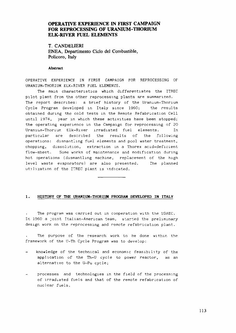
OPERATIVE EXPERIENCE IN FIRST CAMPAIGNFOR REPROCESSING OF URANIUM-THORIUMELK-RIVER FUEL ELEMENTS
T. CANDELIERIENEA, Departimento Ciclo del Combustible,Policoro, Italy
Abstract
OPERATIVE EXPERIENCE IN FIRST CAMPAIGN FOR REPROCESSING OFURANIUM-THORIUM ELK-RIVER FUEL ELEMENTS.
The main characteristics which differentiates the ITRECpilot plant from the other reprocessing plants are summarized.The report describes: a brief history of the Uranium-ThoriumCycle Program developed in Italy since 1960; the resultsobtained during the cold tests in the Remote Refabrication Celluntil 1974, year in which these activities have been stopped;the operating experience in the Campaign for reprocessing of 20Uranium-Thorium Elk-River irradiated fuel elements. Inparticular are described the results of the followingoperations: dismantling fuel elements and pool water treatment,chopping, dissolution, extraction in a Thorex acid-deficientflow-sheet. Some works of maintenance and modification duringhot operations (dismantling machine, replacement of the highlevel waste evaporators) are also presented. The plannedutilization of the ITREC plant is indicated.
1. HISTORY OF THE URANIUM-THORIUM PROGRAM DEVELOPED IN ITALY
The program was carried out in cooperation with the USAEC.In 1960 a joint Italian-American team, started the preliminarydesign work on the reprocessing and remote refabrication plant.
The purpose of the research work to be done within theframework of the U-Th Cycle Program was to develop:
- knowledge of the technical and economic feasibility of theapplication of the Th-U cycle to power reactor, as analternative to the U-Pu cycle;
processes and technologies in the field of the processingof irradiated fuels and that of the remote refabrication ofnuclear fuels.
1 1 3

The basic facility for the execution of this research workis the fuel Element Processing and Refabrication Plant (ITREC)built at the TRISAIA Center.
For the hot experiments in ITREC plant have been utilizedthe fuel elements of the Elk River Reactor first core.
In 1974 the Italian Committee of Ministers for EconomicPlanning (CIPE) decided to stop the U-Th Fuel Cycle Program.In accordance with that resolution and as regard the ITREC Plantit was decided to stop all activities concerning the fuel remoterefabrication and was planned to use ITREC as a pilotreprocessing plant for the performance of hot and cold testingon advanced components (centrifugal contactors, continuousdissolver etc.).
2. GENERAL CHARACTERISTICS OF THE ITREC PLANT
The ITREC (Reprocessing and Refabrication pilot plant offuel elements of the ceramic oxide) differs from mostreprocessing plants in the following main aspects:
- the plant was originally conceived and built as anintegrated unit for the reprocessing and for the remoterefabrication (Fig. 1);
- among the various possible methods for the processing offuel elements containing uranium and thorium, that used in theITREC does not involve the separation of thorium and uranium andtherefore, after extraction of the fission products, theprocessed material contains Th-228, a strong gamma emitter whichmakes it impossible to handle the material without adequateprotection. The refabrication must therefore be carried out in acell fitted with adequate shielding, using remote-operatedequipment and techniques;
all equipments of the main chemical processing areinstalled in modular units (the Racks Removal System), anarrangement which provides for the remote-controlled removal(after appropriate decontamination) of the individual mobileunit (rack) for maintenance work and modification of componentsand equipments.
Thanks to this arrangement it is also possible, withoutparticular difficulties and at limited cost, to replace entirelycomplete sections of the plant to adapt it to new research
114

program. For example, the experiment with centrifugalcontactors in the extraction section will be possible by simplyreplacing the equipment installed on a single movable rack.
This feature, as well as the various alternatives envisagedin the original design, makes the plant extremely flexible.Thus, for instance, the plant can carry out the Th-U co-decontamination flow-sheet as //ell as the Th-U partition flow-sheet. Also, in the case of adaptation to the reprocessing offuel from different reactors, the plant is equipped for both thereception and pool storage of the new type of elements and foran increase in dissolving capacity (from 15 to 30 Kg/d).
3. REMOTE REFABRICATION CELL: COLD TESTS
In the remote refabrication cell (warn cell) is carried outthe last phase of the chemical process and the last cycle of theoperations connected with the mechanical refabrication of thefuel elements.
From 1968 until 1974, year in which these activities havebeen stopped, the refabrication equipment has been tested with Uand Th not irradiated, in order to optimize the various processconditions and to improve the remote operation procedures.
All these operations are indicated in the Fig. 2.The coprecipitated Th-U oxalates are converted into oxide bycalcining the oxalate cake at 920°C.Green pellets are obtained by cutting the extruded rods intopieces after drying.To carry on the ceramic fabrication in remote handlingconditions a considerable amount of work was devoted todevelopment of special tools.Table I summarizes the characteristics of the sintered pelletsobtained since the process was set up in the main lines. Withexception of two lots, the number of the pellets meeting thespecific density is 90%.After loading the accepted pellets into the tube the second endplug welding is remotely performed.Metallographie checks demonstrate that the quality of remotelyperformed welds is up to the standard of the welds made bydirect operation.All the welds are routinely Xrayed in an apparatus which wasdeveloped for the purpose.The pins are assembled into an Halden type element still insidethe refabrication cell.
1 1 5
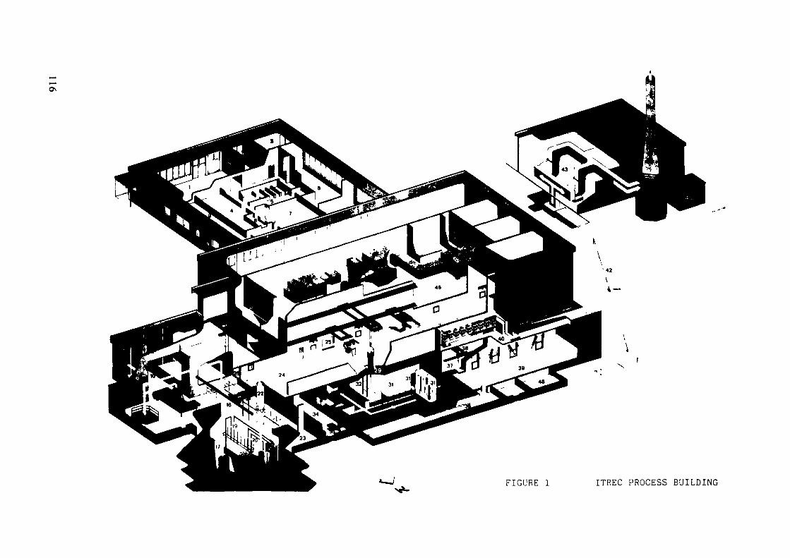
FIGURE 1 ITREC PROCESS BUILDING
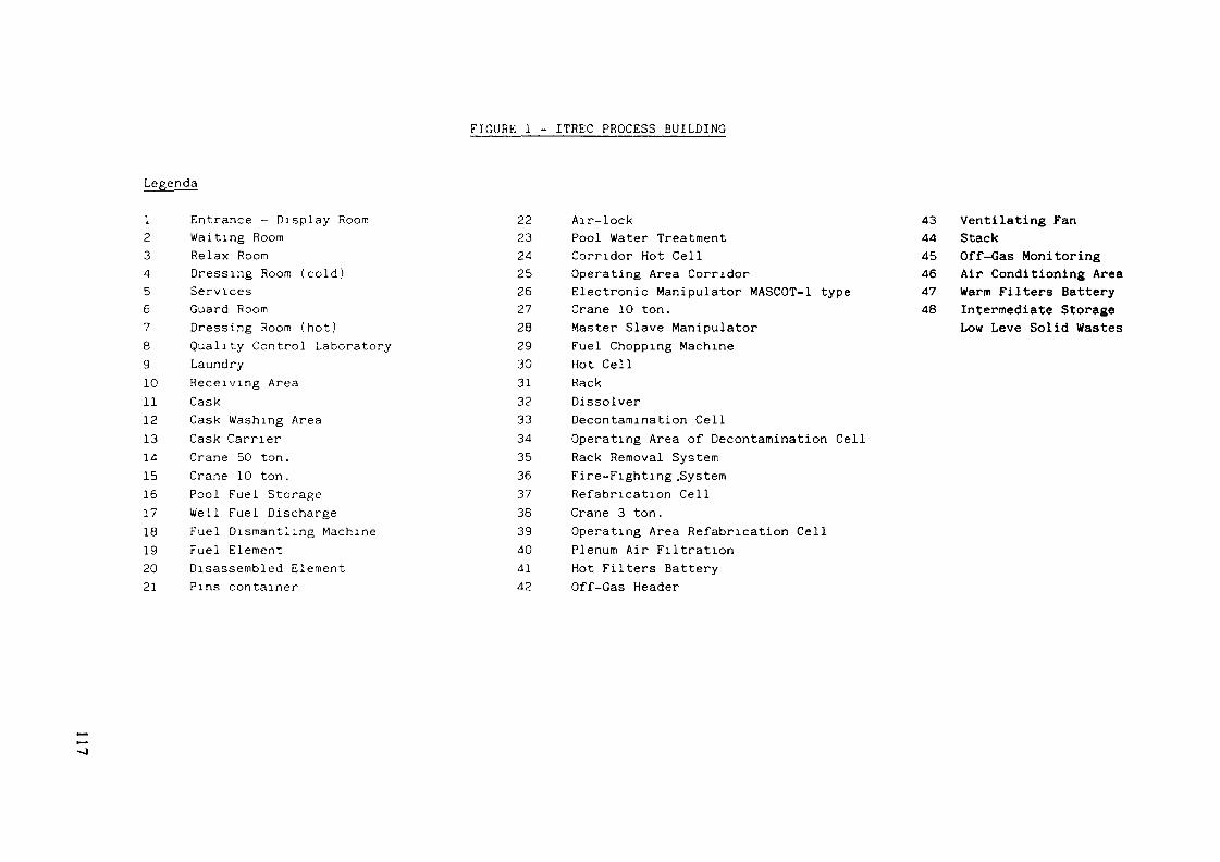
Legenda
FIGURE 1 - ITREC PROCESS BUILDING
1 Entrance - Display Room2 Waiting Room3 Relax Room4 Dressing Room (cold)5 Services6 Guard Room7 Dressing Room (hot)8 Quality Control Laboratory9 Laundry10 Receiving Area11 Cask12 Cask Washing Area13 Cask Carrier14 Crane 50 ton.15 Crane 10 ton.16 Pool Fuel Storage17 Well Fuel Discharge18 Fuel Dismantling Machine19 Fuel Element20 Disassembled Element21 Pins container
22 Air-lock23 Pool Water Treatment24 Corridor Hot Cell25 Operating Area Corridor26 Electronic Manipulator MASCOT-1 type27 Crane 10 ton.28 Master Slave Manipulator29 Fuel Chopping Machine30 Hot Cell31 Rack32 Dissolver33 Decontamination Cell34 Operating Area of Decontamination Cell35 Rack Removal System36 Fire-Fighting .System37 Refabrication Cell38 Crane 3 ton.39 Operating Area Refabrication Cell40 Plenum Air Filtration41 Hot Filters Battery42 Off-Gas Header
43 Ventilating Fan44 Stack45 Off-Gas Monitoring46 Air Conditioning Area47 Warm Filters Battery48 Intermediate Storage
Low Levé Solid Wastes

oo
fta
caiv
ing
Po
ol
Ar»
Rep
roce
ssin
g
flOllt III« r tactO'
Waif'ing anddecontamination
ol luel caakT
L.L Fuel «lern«n|unloading
and iloi«Q«
Fuel «lamentdian\anllmg
Fuel lubecliQppinq
Ditjolullon
-L.Solution
adjuiimirii
Higli-acllvltrliquid *aaia» Solvant
Ediaclion
Concanliallon
Concanlraliuo
lo W«itaTraatmanl Building Adiuilineol ol
U/Th rallo
Slamlait tlaal icrapTo Solid RadioaclivaWatla S to raga
Sta in less s tee l s c r a pTu Solid Rodioaci iveWas te S lo fage
Solve'il scrubbingand («cycl ing
Remote Refabrication
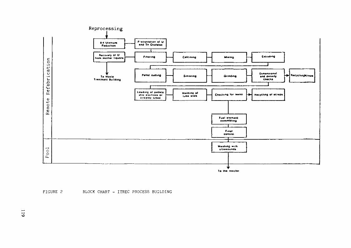
Rem
ote
Ref
abri
cati
on
Reprocessing
To W*il*T(«>lm*nl Bullding
•-4 U'iniumReduction
fi«co»»ry öl Uliom mom»f liquor»
P.-ccipililion öl U•nd In O«*l*l*i
1
Calcining
JLloading ol pallaltinto tiainieat orurcaioy lutxi
U » Ing EiUudmg ]•nd d*n*ity
cn*cks
W»ld.no oflub* «ndi Ch*cking lot tackt Htcycline öl tciapi
••»•mbling
connol
coo.
ullimounat
To in* i«»cior
FIGURE 2 BLOCK CHART - ITREC PROCESS BUILDING
\o

K)OTABLE I CHARACTERISTICS OF A SAMPLE OF SINTERED PELLETS
OBTAINED DURING PRENUCLEAR TESTS IN REFABRICATIONCELL
LOT No
11
12
13
14
15
16
17 (•)
1B
19
20 (")
21
Pellets pro-
duced
61
49
72
03
60
55
63
54
37
57
56
DENSITY
X of pellets
»eel Ing spee.
90
53
100
97.6
88
100
20
80 {•*•)
90
C
32.7
AVERAGE SHRINKAGE %
0
20.52
19.02
22.96
23.10
21.96
23
22.01
20.91
21.11
23.27
22.41
Lenglh
21.11
19.25
20.17
20.02
19.07
20.53
21.07
19.19
19.45
20.00
11.73
Volume
50.16
47.05
52.63
52.36
50.70
52.6
53.17
49.16
49.85
53.36
51.69
Weight
2.49
1.70
1.07
1,81
1.B4
4.45
2.16
1.65
1.49
1.84
1.81
BEND
Average Value
0.36
0.48
0.34
0.34
0.35
0.35
0.20
0.30
0.30
0.31
0.19
Standard
Deviation
0.15
0.17
0.11
0.12
0.12
0.1
0.14
0.20
0.09
0.10
0.07
_n_ (••*•)
"l
24.5
18.4
38.9
41.0
23.1
14.5
20.6
20.4
10. 9
26.3
22.2
••OTES:(•) - Loi excessively M healed In • ! xer-nwller; quantity of PA* doubled and clay re-worked In «ixtr-wlltr
(M) - Extrusion pressure excessively low (0.15 lon/c* Instead of th* regular v»lu«^> 0.3 lon/c« )
(•••) _ p«Het« out of »pec. only for density higher than <Jt% Uieor. Vary high extrusion pressure applied
{•*»•) _ n . nunber of pellets within x » 6~ t (x • average bend, S • standard devlalloo, t • Student's factor. Probability 0.05,~n . mraber of pellets produced).

A number of modifications, suggested by work experiencehave been made on the various unit operations to optimize theceramic process and the equipment functionality (for example thesol-gel process instead of oxalate precipitation andpelletization instead of extrusion).
4. ERR FUEL CAMPAIGNS RUN IN ITREC PLANT
Following the decision to phase-out the remote fabricationactivity, only the chemical process section of the plant,together with the mechanical head-end (fuel assembly,dismantling and individual pin cutting) has been put into activeoperabion.
The hot operation has been started in July 1975, with thereprocessing of 20 ERR Th-U spent fuel elements, irradiated inthe Elk-River (USA) reactor. For this first campaign the maximumcooled and less irradiated elements have been chosen, whicncharacteristics are reported in Table II.
The experience acquired in the hot operations can beconsidered as complete and regards the following activities-
Mechanical operations in the receiving, dismantling andchopping of fuel elements.
Chemical processes in the unit operations as dissolution,feed adjustment, solvent extraction, solvent recovery,wastes and pool water treatment.
4.1. Receiving and Dismantling Area
In case of the receiving area, hot work experience regardsthe cooling, washing and unloading of the 3 Elk River casks.The dismantling operations involved 36 of the 84 Elk River fuelelements stored in the ITREC pool.The dismantling operations showed that the machine was notfunctionally perfect because of its complexity.
The principal troubles were experienced in the.
deformation of the element holder along the vertical axis
block of the knife extractors probably due to seizure
oxidation and deformation of the rotable finger dueto error in the choice of materials.
121

TABLE II ISOTOPIC COMPOSITION AND ACTIVITY
1 SOT O P I CCOMPI S1TI ONTh-232 KQU— TotU-23SU — 2 3 3U - 2 3 9
ACT IV l TV
Gro»»c< Cl/KgUC5r- 09 * p "
G™.^
20 ELK-RI«,.'ER ELEMEMTSREPROCESSED
4?-5.XrO
2 O . 4 7 O1 A . 34S
1 . 4̂ .S2 . 1 T7" 0
3 . 7SO23<* . 54OÇ4 . 23O
EVALUATED DATA FOR OTHER•*4 ELK — RIMER ELEMENTS
1 303 .I0O44 .71043 . 2707.8198.410
14.9092 . 4001.100
Therefore, a series of complexed operations (decontamina-tion, extraction from the pool etc.) were made for a radicalmaintenance of the dismantling machine.The pool water treatment takes place on a mixed resin bed afterfiltration.
4.2. Fuel Chopping and Dissolution
After the dismantling of the fuel element assembly, eachpin was cut into 2 cm. pieces, which fall into the dissolver.
A Thorex "acid-deficient" flow-sheet was used for thecodecontamination of U-Th in a single cycle 30% TBP solventextraction.
In case of the chopping and dissolution section hotoperation has confirmed the good results of the prenucleartests.
The dissolution yields on the 4 batches are astheoretically foreseen, whereas on the first 3 batches (inputsolution) they are 98-99% for Th and 99.5-99.8% for U.Visual examination of the hulls and the spectrum of a sample ofhulls analyzed prove both the perfect chopping operation and thecomplete dissolution of the nuclear materials.The losses of HNO in the OFF-GAS dissolver give approximately10 - 12% when, during chopping, the dissolver solutiontemperature reaches 100°C and drop to 6 - 7% when the attacksolution is at room temperature.
During hot operation the complete chopping group wasreplaced in order to check the remote intervention system.
122

4.3 Extraction system
For the first campaign the flow-sheet selected, from arange of possibilities due to the extreme versatility of theplant, was U-Th co-decontamination (Fig. 3/4).
The U-Th product is stored as concentrated solutions ofUranyl and Thorium nitrate with the possibility of recycling inthe input tank for the subsequent Th-U partition campaign or thesubsequent sol-gel process conversion. (Tab. III).Theoretical FP's decontamination factor is about 5 . 10 forbeta-emitters and 5 . 10 for gamma-emitters. Actualdecontamination factors in normal operating conditions wereabout 1000 for gross-beta and about 1000 for gross-gamma.
The hot run was stopped twice: firstly because of amicroloss appeared in HLW evaporator (which concentrates theacqueous raffinâtes 1 AW flow from first co-decontaminationextraction battery) and secondly for the obstruction in theextraction mixer-settlers battery. The second maloperation hascaused the bad decontamination of end product and therefore thestored product is a mixture of the end products obtained fromthe normal and abnormal operations of mixer-settlers battery. InFigg. 5/6 is reported the behaviour of gross-beta and gross-gamma Decontamination'3 Factors as well as for some particulargamma-emitters, during the normal plant operation.
In the 1AW current the losses of Th are very near to thetheoretical values of approximately I0/ while it ispractically impossible to determine the losses of U (*l°/oo; theconcentration found is at the sensitivity limit of the testmethod).
In the re-extraction section theoretical and actual lossesalso proved extremely low.
In conclusion, the process may be considered operativelysafe and satisfactory.
4.4. Remote Maintenance
In general the maintenance philosophy of the hot facilitiesin the plant is based on remote removal and transfer of parts tothe decontamination cell. In the ITREC Plant two differentapproaches have been chosen to solve the practical problemsconnected with this philosophy:
123

ro H 0=0,04Kg/Kg
NO =0,033M/Kg
FP<0,2Ci/Kg
208Kg/2gi,orm
tCONDENSER
(CHOPPER) * r"^
Th =252€&Kg/el HO =0^6Kg/KfU =1 .354 " HNO =Oß7^K{FP =1027 Ci/cl 3
HO =0,02 "
1 elem/2days5]OKg/2 days
HNO 1 , 55M•J
295 1/2 days
•4 ———————————————
rcTh = 4,er>g/i >U = 0,242 " g
HNO = 13 M
F = O.O4H
90 1/2 duys„* = 1 1 . 1 5 M — >• -
33 1/2 days ——————————
o
^ v
% * Th = 5 g/l
S 3 U = 0,25 "
K * H' = 11 ,5 MUl
32 1/2 days
1 '
————— *• OFF-GAS
M. L. WASTE <
Th <
U =12,8 " >.
H' =6.83 M * LJ
" rl' -17 D/1 «
105 l/,1 days =0u
STAINLESS bTLEL
T1.ADDING ACTIVATION
PRODUCTS - 12 Ci /Kg ——————
V5 Kg/ 2 days SOLID WASTE
EXTRACTIOM _j
HNO 2 M4"
182.9 I/day
TU
-*• HF
1
U)K«<tnz— UlQOU
H<U.
r
z
X0H
h =22= 32
* =6.P =16
9.78/1.3 "
,2Cl/l55 1/day
| SO
LVEN
T E
XTR
AC
TIO
N
|
zf-aUlUlu.
_ F. A. T.CONDENSER
t
H11Î-1
0U)Ulu.
\
zH
Th « 267 g/lU = 14,3 "H* = 0,15 MFP = 18.8C1/147,31 1/day
4 >
HEAD
EN
DTR
EATM
ENT
TANi
'v
t
Th =315.8 g/1U =16.9 "H* =0,18 MFP =22,3Ci/l40 1/day
REAGENTS
0 1/day
FIGURE 3 HEAD-END REFERENCE FLOW-SHEET
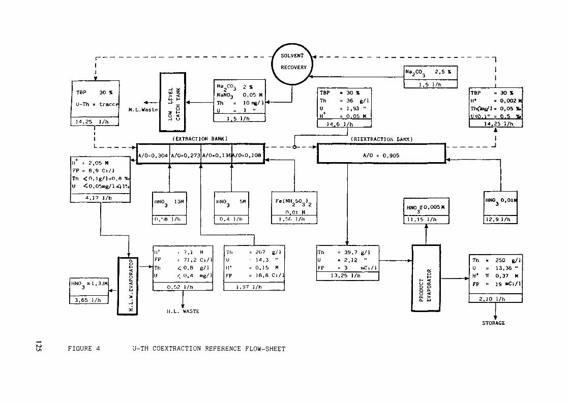
11T
TBP
U-Th =
14,25
30 X
tracce
l/h1
M. L. Waste
u zUJ I-Iu
S 5J O
*
Na C03NaN03ThU
1,5
2 X0,05 M10 ng/11 "
l/h
4 —————— 1TBP = 30 XTh = 36 g/lU = 1 , 93 "H* = 0.05 H
:o 2,51,5 l /h
TBP = 30 %H+ = 0,002 MTh<fcn/J= 0.05 X,IKO.l" = 0.5 V
(EXTRACTION BANK)
II = 2,05 MFP = 8,9 Ci/1Th <0,lg/]=0,8 %U -£O.OSing/l=QlT:
A/0=0,304 A/0=0,273 A/0.0. 1 36 \/0=0. 108
U*FPTh
= 7,1 M= 71 ,2 C l /1<0,8 g/l'. 0.4 mg/ 1
0,02 l/h
II. L. WASTE
STORAGE
K) FIGURE 4 U-TH COEXTRACTION REFERENCE FLOW-SHEET
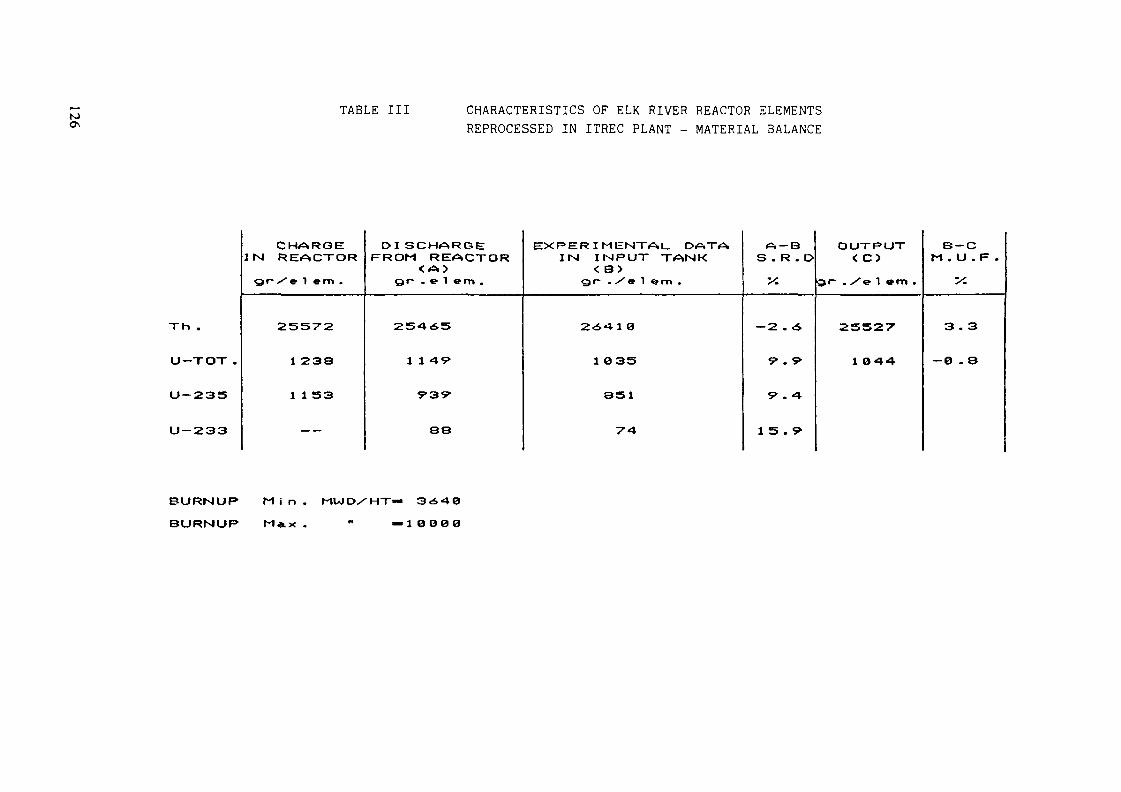
N) TABLE III CHARACTERISTICS OF ELK RIVER REACTOR ELEMENTSREPROCESSED IN ITREC PLANT - MATERIAL BALANCE
Th .
U— TOT .
U-235
U — 233
CHARGEIN RE«a»CTOR
Qf~ >"e 1 em .
25572
1 238
1 1 S3
— -
D I SCHERGEFROM REACTOR
< A>gr~ .el em .
254,65
1 1 4V
rsv
88
EXPERIMENTAL. D^TAIN INPUT TANK
< B>gr~ ./el em.
2<£.«*1 0
1 335
351
T'A
A — BS . R . D
X
— 2 . A
Ç> . 9-
9 . 4
1 5 . 9>
OUTRUT< C5
Q(~ . /e 1 em .
25527
1 044
B — CM . U . F .
•y.
3 . 3
-0 . S
BURNUP M i n . MUID/HT=»BURNUP M AX. " —10O00

lOOOOOf
lOOOOOj
toooo.
1000 .
100 .
10 .
a F.
T5 tcg/u
FIGURE 5 DECONTAMINATION FACTOR
lOOOOOj
100000.
10000.
1000 .
100 -
10 _
D. F.
O-137
r2
T3
rs
rs
FIGURE 6 DECONTAMINATION FACTOR
127

1) first approach is installation of all apparatus onremovable racks that can be transferred tothe Decontamination Cell.
2) second approach is adaptation of every major item by itselfas suitable for handling with regularmaster-slave manipulators.
The first approach (Rack Removal System) has been adoptedin the reprocessing section, where the removal of each rack iscontrolled through positive mechanical devices in so strict asequence that no provision has been made to even see theoperation (no shielding window or camera).After long operation the system has not induced any suspicion ofdeveloping faults and is currently considered as proven.
The second approach inspired the installation of therefabrication equipment. Every item was custom made to fitindependently into a general arrangement of the cell, thatprovides supports and connections preset accordingly to amodular disposition. This accomodation required a considerableamount of engineering work but resulted in more compact andflexible arrangement.
The transfer of equipments to and from the decontaminationcell, and of irradiated fuel from pool to process is donethrough the "corridor" which is an area of restricted access.An electronic manipulator has been added. The manipulator is ofthe "Mascot" type, developed by ENEA. It has proved to be mostuseful as a substitute for man in fine adjustment jobs.
4.5. Operational Troubles
The number and variety of incidents which occurred made itpossible to gain wide experience in the hot maintenanceoperations and at the same time had no consequences foroperators or for the environment.Most of these maintenance operations have concerned:
clogging in the sampling system
obstruction of ejectors
blockage of remote head pumps in the extraction process
chopping machine
The most serious problem concerned the leak on the steampiping of the H.L.W. evaporator. (Fig. 7).
128
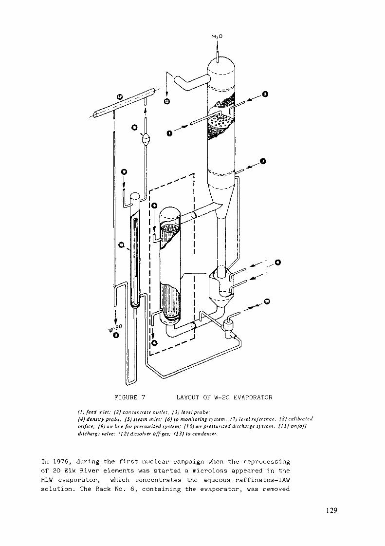
H,0
FIGURE 7 LAYOUT OF W-20 EVAPORATOR
ID feed inlet; (2) concentrate outlet. (31 level probe:(4) density prob«. (5) steam tn'.ei; (6) to monitoring syitem. (7j level reference, (Sj calibratedorifice; (9) air line for pressurized system; (101 air pressun:ed discharge system. Ill) on/offdischarge valve; (12) dissolver off-gas; (13) to condenser.
In 1976, during the first nuclear campaign when the reprocessingof 20 Elk River elements was started a microloss appeared in theHLW evaporator, which concentrates the aqueous raffinates-lAWsolution. The Rack No. 6, containing the evaporator, was removed
129
from the hot cell to the decontamination cell. It is the sectionmore difficult to decontaminate as it includes the first mixer-settler extraction battery and the evaporator of the 1AW flow.
The decontaminating solutions used are stocked in the HLWand/or LLW tanks of the plant. The need to ensure compatibilityof a long storage of these solutions with plant materials(AISI-304L), has brought to the exclusion of all commercialdecontamination agents, because highly corrosive, whoseefficiency is based essentially on the combined action of highoxidant substances with high complexing power.
Decontamination of the mixer-settler battery and of rackNo. 6 was completed in the decontamination cell by successivewashing with: Na CO at 20%; COO(NH ) = 0.3M + EDTA = 0.18M;HNO = 6M, using for every washing 100 It. of solutionintroduced in the first stage of the battery and subsequently inother equipment.The removed exchanger suitably packed and enclosed in a specialcontainer, will be examined internally to verify causes anddegree of damage to the steam piping.After decontamination the intensity of exposure in contact withthe shell reaches the maximum values of 300-500 mR/h.During the intervention on the evaporator 3 ejectors have beenreplaced because of the frequent obstructions during the hotoperation, especially due to solid particles contained in thesteam.
The total dose for the whole intervention in thedecontamination cell was 2.4 rem, distributed among 19operators. The maximum individual dose was 433 rem, absorbedduring 14 interventions in a 60-day period.The duration of the hot intervention was 34 hours and 13minutes, representing 113 man hours.
After the intervention the rack No.6 was replaced in thehot cell and the hot plant operations were restarted to completethe reprocessing of the remaining 13 Elk River fuel elementsplanned for the first nuclear campaign.
5. NEXT PROGRAM OF ITREC PLANT UTILIZATION
In accordance with the strategic destination of the ITRECplant the next program foresees the following main activities:
2nd Hot Campaign (1986-1987) with the reprocessing of 16U-Th Elk River fuel elements for hot tests of a specialtype centrifugal contactors in the extraction section.
130

3rd Campaign for U-Th partition, recycling in the plant theuranyl and Th nitrate solutions produced in the First andSecond Campaigns and subsequent Uranyl nitrate conversionby sol-gel process.
Experience on the decommissioning technology within theframework of the C.E.C. Program.
Experience on the storage of spent fuel elements utilizingone lot of the Elk River fuel elements.
131

SUMMARY OF PAPERS
Nine papers were presented at the meeting, dealing with thefollowing:
evaluation of world thorium resources and incentives for furtherexploration;
basic research of physical, chemical and nuclear properties ofthorium;
reactor core and blanket concepts regarding utilization of Th-basedfuel;
advanced thorium fuel fabrication technology;
reprocessing of Th-based fuel.
1. Evaluation of world thorium resources and incentivesfor further exploration
Thorium in association with uranium and Rare Earth Elements (REE)occurs, as shown in the paper presented by Mr. Jayaram, India, in diverserock types: as veins of thorite, thorianite, uranothorite and as monazitein granites, syenites, pygmatites and other acid intrusions. It alsooccurres as an associated element with REE bearing bastnaesite incarbonites. Monazite also occurs in quartz-pebble conglomerates,sandstones and in fluviatile and beach placers.
The current knowledge of thorium resources in the world is smallbecause of the relatively low-key exploration efforts arising out ofinsignificant demand. Resources recoverable at less than $80/kg Th inthe Reasonably Assured Resources (RAR) and Estimated AdditionalResources-Group (EAR-I) categories are estimated at around 1.4 milliontonnes and one million tonnes respectively. And this is due only to theeffort made by several countries to identify either uranium or REE.India has about 31% of them. Argentina, Australia, Brazil, Burma,Canada, China, Republic of Korea, Indonesia, Malaysia and South Africa
133

have also considerable resources of thorium. The possibility ofdiscovering new resources, in addition to increasing the known resourcescontained in the deposits already known, is good.
In spite of today's apparent unfavourability for the thoriumutilization situation in the uranium market (low prices for uranium andoversupply) it seems that the perspective of thorium utilization as anuclear fuel is realistic in the near future. This could be justified bythe forecast for uranium utilization in both once-through or closed fuelcycles. Also countries which have limited resources of uranium may haveto use thorium to ensure continuous growth rate of electricitygeneration. Taking this into account the IAEA will contribute further tothe exchange of information and co-ordination of national efforts aimedat maintaining and improving knowledge on thorium resources and itsutilization as a nuclear fuel.
2. Basic research of physical, chemical and nuclear propertiesof thorium
In general fundamental investigations are concerned with preparingthe base for studying the physical properties of nuclear reactors,working with either a mixed fuel cycle or Th-based fuel.
The dependences of U-233, U-232, Pa-233 and fission products buildupupon integral thermal neutron fluxes in high flux ETR-reactor (China)have been studied, including detailed correlation between theabove-mentioned values and fast to thermal flux ratios in wide range.These results may be helpful in assessing breeding potential of Th-basedfuel in different type of reactors. French work (Attachment IV) onrevising and réévaluations of Th-232, U-233 data revealed the following:
The value of Th-232 absoption in thermal range is apparentlywell-known, though absorption cross sections seem to decrease morerapidly than f\j law. Accurate experimental values should be desirableto improve temperature coefficients forecast. The most desirable furtherwork is in high energy range. The knowledge of U-233 cross sections nowis not as good as that of Th-232. Further work is still needed,particularly in the thermal range of energy. This work should include anew accurate measurement of V ,Of, fission spectrum, as well as,benchmark "clean" critical experiments, which can be easily interpretated.
134

3. Reactor Core and Blanket Concepts Regarding to Th-based Fuel Reactors
Strategy investigation, reactor core and blanket design are stillimportant for successful development of Th-based fuel reactors.
The current state of the reactor and fuel cycle facility developmentsuggest the following logics (USSR) in combination with theuranium-plutonium and uranium-thorium cycles for nuclear power.Transition to the U-Pu closed cycle, development of spent fuelregeneration, plutonium accumulation paves the way for rapid introductionof fast breeder reactors which are to be the basis of future nuclear fuelbreeding. The accuteness of fuel problem can be then eased by transitionof the thermal reactors to utilization of the U-233 accumulated in thefast breeder reactor blankets. That idea is supported by the Indianplans for the behaviour Th-232 investigations in blankets of fast testreactors.
There is, among others, the French idea to use Pu-Th cycle inunmodified PVRs. The main goal of this work is to find a real way foropening the Th-cycle in up-date reactors. The solution proposed consistsof initial loading the whole reactor PWR-type with Th-Pu assemblies.Besides, it is an attractive means of storage plutonium in case ofrather slow development of LMFBRs. U-233 can be perfectly used inSpectrum Shift Control Reactors. Regarding optimization of neutronics,calculations were being made, including pin power peak, moderatortemperature coefficient etc.
Other optimistic results were described in cooperativeBrazilian-German paper on Th-utilization in unmodified PWR typereactors. It can be established, that standard PWR may use (Th, U)0fuel and even (Th, Pu)0 fuel without any changes within the reactorsystem. A favourable strategy to avoid the need of early reprocessingand to strive for savings in uranium might be the use of (Th, Pu)0fuel in the once-through cycle with extended burnups.
4. Advanced thorium fuel fabrication technology
For refabrication of U-233 bearing HTR fuel kernels the EGT(External Gelation of Thorium) sol-gel process has been developed (paper.
135
presented by Mr. Zimmer, FRG). On the basis of this technology developedfor HTR fuel production, a procedure for production of fuel pellets forwater cooled reactors has also been developed (paper, presented by Mr.Peehs, FRG).
Three major modifications were made in the referred EGT process inorder to produce gel microsphere which could be calcined to microspheressuitable for pelletization and sintering. First, heavy metal nitratefeed solutions of lower molarity were found to be more suitable.Secondly, calcium nitrate was added to the feed solution in order to havearound 0.4 w/o CaO "sintering aid" in the subequent calcinedmicrospheres. Thirdly, carbon black were added to the sol prior togelation. The pores formed in the sol-gel microspheres after burning offthe carbon black particles reduce the crushing strength of themicrospheres and facilitate pelletization.
The Sol-Gel Microsphere Pelletization (SGMP) process not only avoidsdust generation and is easy to remotize but also produces high densitypellets of desired microstructure at compaction pressures and sinteringtemperatures, which may be even lower than for the conventional powderroute.
HTR fuel kernels are easily produced by the EGT process which needsno chemicals apart from NH, necessary for precipitation of heavy metalsin all fuel production processes.
In the paper regarding Indian experience in fabrication of ThO?pellets emphasize was made on optimization pre-compacting and finalcompacting parameters which will lead to the reliable and economicfabrication technique of this fertile material.
The goal of this work is fabrication and supply of blanketassemblies containing thorium oxide pellets to the requisite quality, forfull core of Indian Fast Breeder Reactor at Kalpakkam.
Starting with ThO powder obtained by oxalate precipitation andcalcination, green pellets are produced through powder metallurgicalroute. In order to achieve sintered densities more than 94% addition ofMg in small quantities, during oxalate precipitation stage.
136
An economic and viable recycling method for sintered pellets as wellas powder needs to be developed.
5. Reprocessing of Th-based fuel
KFA Julien GmbH experience in the utilization of dual cycle THOREXprocess for extraction of Th and U was reported (by Mr. Zimmer), as wellas, the results of cold tests.
The THOREX solvent extraction process is simple to carry out sinceseparation of Th and U is accomplished by the different extractionbehaviour of the elements in their stable valency state, rather than inthe PUREX process where the Pu has to be reduced to and stabilized in thetrivalent state for separation.
Reprocessing of the 20 ELk-River reactor (USA) Th-U spent fuelelements was done in the ITREC plant, Italy (paper by Mr. Candelieri).The ERR used fuel had a burnup in the range of 3,650 -10,000 MWd/t. ATHOREX "acid-deficient" flowsheet was used for code-contamination of U-Thin a single cycle 30% TBP solvent extraction. Unfortunately, the projectterminated in 1974 and the facility is presently used for testing some ofthe components used in a reprocessing plant. No pellet refabrication hasbeen done in this facility.
137
SUMMARY OF THE PANEL DISCUSSION
In spite of some leveling in the demand for nuclear energy and insome decrease in U-costs a number of IAEA Member States are stillinterested in the utilization of Th as nuclear fuel. This is in order toevaluateed long-term fuel supply and to prevent for shortages in enrichedU. RAR and EAR-I resources of Th which could be recovered at costs lessthan US $80/kg are estimated at around 2,4 million tonnes.
Conventional nuclear power plants can be designed for operationeither in the U/Pu cycle, in Th-HEU cycle or in Th-Pu cycle. The mainadvantage of the Th-based fuel cycles is that is has a higher neutronyield of U-233, in comparison with the neutron yield of Pu 239 in theU/Pu cycle. Those benefits may be equalized by commercial disadvantage,due to the requirement of HEU and the problems related to reprocessingand refabrication in a closed fuel cycle since full remotization isneeded. The once-through cycle by the use of Th/Pu fuel offers thepossibility when applicated to LWR-systems to avoid those problems andhaving considerable savings in U-ore and enrichment work units.
In fundamental and reactor conception problems the papersconcentrated mainly on the following questions: are there enoughneutronics data and how to choose the optimal way for starting theTh-based fuel cycle in nuclear power, to prove the neutronic feasibilityof thorium cycle in unmodified PWR's For other types of reactors thereare no real plans involving a Th-based cycle. FRG has abandoned theutilization of Th in the future HTRs in favour to low enriched uranium.The reason is the current inavailability of HEU.
A crucial item in the nuclear core design is the uncertainties inthe cross-section data for Th-232 and U-233. In France, CEA recommendeddata is in use which is updated from time to time. The work in this areais summarized in the enclosure, presented by the French delegate, Mr.Greneche from CEA, Saclay. In general, the data for Th-232 are morereliable than those for U-233. In the FRG data are used which areelaborated by detailed studies based on the available experimental database and from irradiation experiments. China feels necessary toelaborate those data more in detail, specifically for LWR application.
139
In India an Expert Group is working on data for thermal and fast fluxconditions. USSR is working with ABBN data (Russian origin) but alsodata from Japan and France are used to improve the data base.
For fuel manufacturing at least four different procedures are inpractice:
Powder production ex-oxalates and cold processing, sintering inH /Ar atmosphere;Powder production ex-oxalates and extrusion, sintering in H /Aratmosphere;
- Vibrocompaction of sol/gel kernels;- Pelletizing ex sol/gel kernels and sintering in H /Ar
atmosphere.
It is acknowledged that the microstructure optimization is neededfor high burnup fuel. This can at the moment only be reached bypelletizing ex sol/gel kernels, improved in its pressing performance bythe addition of carbon black (Brazil, FRG). Fuel fabrication for blanketelement do not need a micro-structure optimization due to its lowburnup. Here the powder production ex oxalates and cold processing showssufficient performance (India). To lower the sintering temperaturesintering aids like Ca or Mg are successfully in use (FRG, India).It was also emphasized, that the time for fuel dissolution in thereprocessing is influenced by its microstructure (FRG, Brazil). Also theaddition of Ca or Mg seems to influence positively the dissolutionbehaviour (India, FRG) of irradiated fuel.
The thermal design of pin-type fuel is not very much advanced. Itseems that in the different countries different material data areused and different computer codes. Some countries are doing ownmeasurement (Brazil, France, FRG, India) and some are using datafrom literature.
The reprocessing and refabrication is heavily influenced by theradioactive by-products requiring heavily shielded devices. Italyhas some experience in this area by the work with spent Elk Riverfuel from the USA. Generally, basic experiences are available butno work is going on on refabrication for the time being, even if
140

some national strategies need reprocessing and refabrication(France, India).
All work presented in the meeting was addressed to oxide fuel. Thequestion on the potential of metallic Th-fuel could not be answeredin the Panel. However, it seems that work is going on in the USA atANL to investigate this fuel type as a FBR-fuel. Alloys withTh-20%U - 4%Zr and Th-20%U - 10% Pu are under investigation.Irradiation testing up to 100 GWd/t seems to be available. The fuelpins have SS-clad and Na-bonding.
After termination of the Panel Discussion a list of major activitiesworldwide in the area of Th-based nuclear fuels was compiled by thedelegates from the different countries. No information wasavailable in the Meeting from Canada, Japan, Romania and USA. IAEAstaff members, Messrs. F. O'Hara, M. Ugajin and Mr. P. Bull of thePermanent Mission of Australia, prepared the reports on the statusof the thorium-based fuel research and utilization programmes in theUSA, Japan and Australia, correspondingly (attached). The report on"Status of Spent Fuel Management in Canada" presented at the IAEAAdvisory Group on Spent Fuel Management in 1984 and reports by theInstitute for Nuclear Power Reactors, Pitesti, Romania, presented tothe IAEA, in the course of a research contract on "Data base for aPHWR operating on a once-through, low enriched uranium-thoriumcycle" were used for filling the above mentioned list.
141
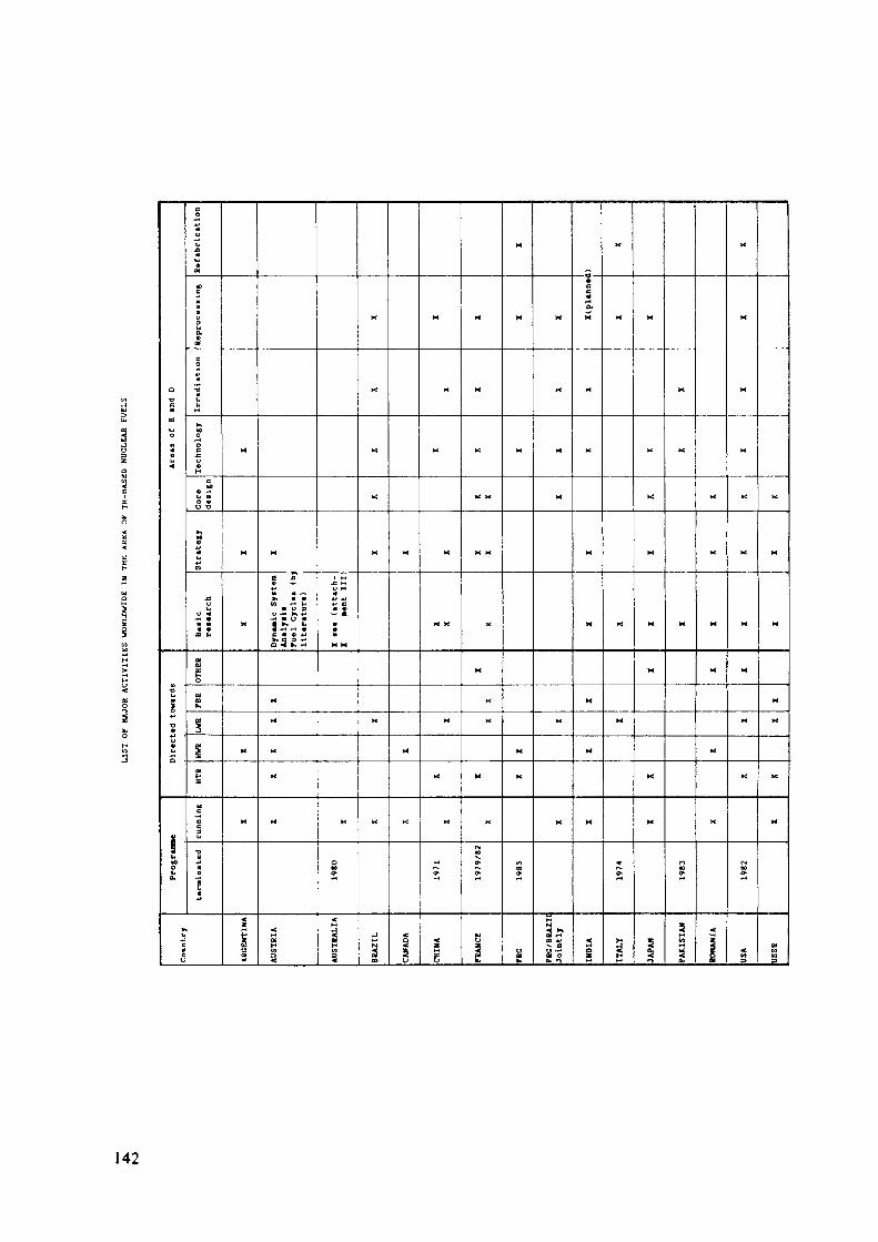
9 *r*c •
*J C
142

Recommendations
The capture cross-sections of Th is rather well-known in the thermalregion. But in the fast energy range capture fission cross-sectionsand n-2n cross-sections must be known with a better accuracy. Thiscould be achieved by differential thermal measurements. For U-233better knowledge of cross-sections is needed in the whole energyrange. For this aim it could be very helpful to have resultsavailable from clear integral experiments (bench-marking). It wouldbe beneficial if this work could be done in cooperation.* Furtherinformation is needed in cross-sections for Pa-233 and U-234.*
It appears that there may be discrepancies in the results obtainedby different countries concerning core calculations for Th cycles(e.g. pin power peak calculations for PWR). It should be worthwhileto promote bench-marking studies on this problem.*
There is a lack of information on the treatment of used Th forclosed Th/U fuel cycles. Work on the reuse of Th would beemphasized.
The powder technology for pelletizing should be investigated toassess its capability to optimize the microstructure of the fuelsimilarly to the pelletizing ex sol/gel kernels.
The Member States working in the area of metallic fuel are invitedto inform about their experience in order to assess its potential ason nuclear fuel. The IAEA is asked to distribute a reference listfrom the available reports in this area.
It is recommended to hold in approximately 5 years a meeting on theprogress in Th utilization. Possible objectives in this areameeting could be the evaluation of world-wide Th resources, basic
The Scientific Secretary was asked in cooperation with the otherDivisions (Nuclear Data Base Section and Advanced Nuclear PowerTechnology Section) to endorse in the Agency the activities oncollection and analyses of data on Th and U-233 cross-sections andon active core designs regarding utilization of Th fuels.
143

research of nuclear, physical and chemical properties of Th,strategies, reactor core and blanket concepts for different reactortypes; fuel technology; reprocessing and refabrication in closed Thfuel cycles.
Upcoming results on the different areas of activity in the Thinvestigation may be presented at the IAEA meeting.
144

Annex ISTATUS OF US PROJECTS RELATED TO THORIUM UTILIZATION
Two major thorium-fuelled reactor programmes have been actualized inthe US. These are the Molten Salt Breeder Reactor and the Light WaterBreeder Reactor. A third, the High Temperature Gas Reactor, wasenvisioned to utilize thorium, but this had not been accomplished.Instead this reactor utilized enriched uranium.
The study and development of molten-salt reactors was begun in theUS at the Oak Ridge National Laboratory in 1947. The potential of MSBRfor civilion power production was recognized and a development programmewas established in 1956. A Molten Salt Reactor Experiment was operatedfrom 1969. It was fuelled with a U235-U238 mixture during the
233initial two years of operation and with U during the remaining 1.5years of operation. The successful operation of MSRE and the favorableprojected system characteristics attracted significant US industrial andutility interest. The development of molten-salt reactors was interrupedin 1973 when the programme was terminated. The programme was resumedbriefly in 1974 but finally terminated in mid 1976.
The second major reactor concept utilizing thorium was the LightWater Breeder Reactor. The concept, then called seed-blanket, wasoriginally introduced in 1951 as a means of minimizing the separativework required for the fuel of a light water reactor. The seed-blanketconcept was employed in tne design of the first commercial PWR plant atShippingport, Penn.
It was long thought to be impractical to breed with light water;233however, since the value of *l for U is only slightly lower in the235 239epithermal region, while that of U and Pu are greatly reduced,
the thorium cycle appeared to be most attractive for a thermal breeder.After preliminary work in tne early 1960s indicated the feasibility ofbreeding in a light water seed-blanket core on tne thorium cycle, the USAEC authorized a demonstration in the Shippingport Plant. This is theLight Water Breeder Reactor Project. Full-power operation of thedemonstration began in December 1977.
145

233The reactor has operated on thorium and u cycles until 1982 atwhich time it was shut down. It is understood that the spent fuel ispresently being reprocessed to provide an accurate check against physicscalculations. Many reports on the project should be forthcoming.
146

Annex IICURRENT STATUS
OF THE THORIUM FUEL RESEARCH PROGRAMMEIN JAPAN
No thorium fuel reactor is currently planned to be built in Japan, butbasic R & D works are under way to pursue the possible diversificationof nuclear fuel resources through thorium utilization in the future.
1. R & D in Japan Atomic Energy Research Institute
The Japan Atomic Energy Research Institute started in 1975 basic R&Dworks on thorium and thorium-uranium mixed oxides to develop laboratory-scale fabrication methods, examine irradiation behaviour and to measurephysico-chemical properties of these fuels.
Microsphere and pellet-type fuels have been investigated taking intoaccount potential applications of the acquired data for the fabricationand performance analyses of both types of nuclear fuels. The main accom-plishments are the following:
- development of new sol-gel process to prepare crack-free microspherefuel with better sphericity aiming at HTGR applications and to preparestarting material for making high-density pellet with varying Th/Uratios ;
- measurement of fission-gas release/irradiation-induced damage anddata analyses to predict irradiation stability and densificationmechanism;
- measurement of new data on equilibrium oxygen potential/stoichiometryand its effect on chemical behaviour of burn-up simulated (Th,U)0_.
2. R & D in Universities
The Research Programme on Thorium Fuel has been performed since 1980on the university basis, under the support of Grant-in-Aid for Energy Re-search of the Ministry of Eduction, Science and Culture of the JapaneseGovernment. The main results have been published in the English-writtenreport "Research on Thorium Fuel (SPEY-9,1984)".
It covers nuclear data evaluation and measurement} reactor physicsexperiment and analysis; fuel fabrication, irradiation and property mea-surement} actinides production/separation and down-stream process deve-lopment; biological effect and molten salt reactor engineering.
147

Annex IIITHORIUM RESOURCE STUDIES IN AUSTRALIA
Australia's thorium resources are those contained in monazite,itself a by-product of mineral sands mining. Australia has some 12780tonnes of reasonably assured resources of thorium (recoverable at lessthan $80/kg TH- however, if monazite was mined solely as a source ofthorium, this resource would not be recoverable at less than $80/kg TH).
There are no specific exploration programs for thorium inAustralia. Exploration effort for mineral sands (containingthorium-bearing monazite) has responded generally to changes in the priceof titanium and zirconium ores.
Thorium is not produced in Australia. All monazite production isexported. Latest production figures of monazite concentrates andcontained thorium are:
Production (tonnes)1983 1984 (prelim)
Monazite concentrates 15141 16707 (prelim)- thorium content 893 969
Summary of work on the utilization of Th-based fuel in Australia(provided by the Australian Atomic Energy Commission).
"The AAEC has carried out four experiments in the area of nucleardata on thorium isotopes: fission fragment angular distriubtions forthorium 232; the average number of prompt neutrons emitted in the fissionof thorium 232; fission fragment angular distributions for thorium 230,and the fission cross-section of thorium 230. The first threeexperiments (concluded by 1980) aimed to examine the existence of atriple-humped fission barrier in the fission of thorium. The data fromeach experiment were in good agreement with such a barrier shape. Thefourth experiment (still running) measured the sub-threshhold fissionresonance in thorium 230 near 715 keV to confirm the energy resolutionand energy accuracy of the first three experiments."
149
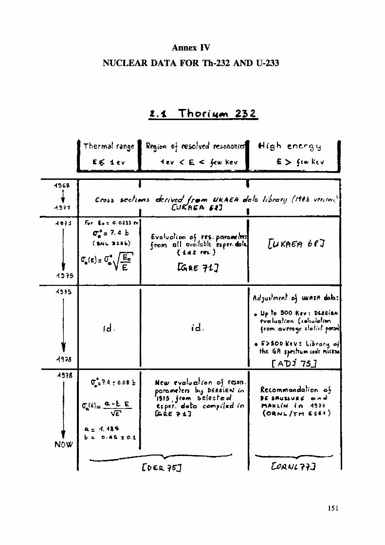
Annex IVNUCLEAR DATA FOR Th-232 AND U-233
Z.I Thon'««* 252
Thermal ran^e 1 Retji*« e| resolved neionow
C£ 1 ev I 4 tv < E < ft«/ kev
esf H igh
€ > ft«, kev
1 l
»m VKACA e/afa li'lraftj (lltï
For Ec - 0.025} t«
( » M UEvaluaNoo oj res. parowetarsfrom all ova iloblt np«f dof»Jrom
rw.)
f d - ld.
<U:
Up ^ 500 Kev : PUBitwfvoluoK'en (colculduenfrom av/rroqr tfoli't
• f>600Kte 6A
! Li^rar<j ,ru M u^c nutM
F 75J
i=?.4 r 0.08 k
_ a-t E
Nevi/ pvoluaff 'en oj roen.poroit^yerj k^ l>£Rßi6Nf .'o
,tipcr. data co*npi"|ed i'nfcfce ?il
Rccommandau'on o]P ( S f * U U U f l f O «A J
in
NOWb =. 0*6 t O.I
151


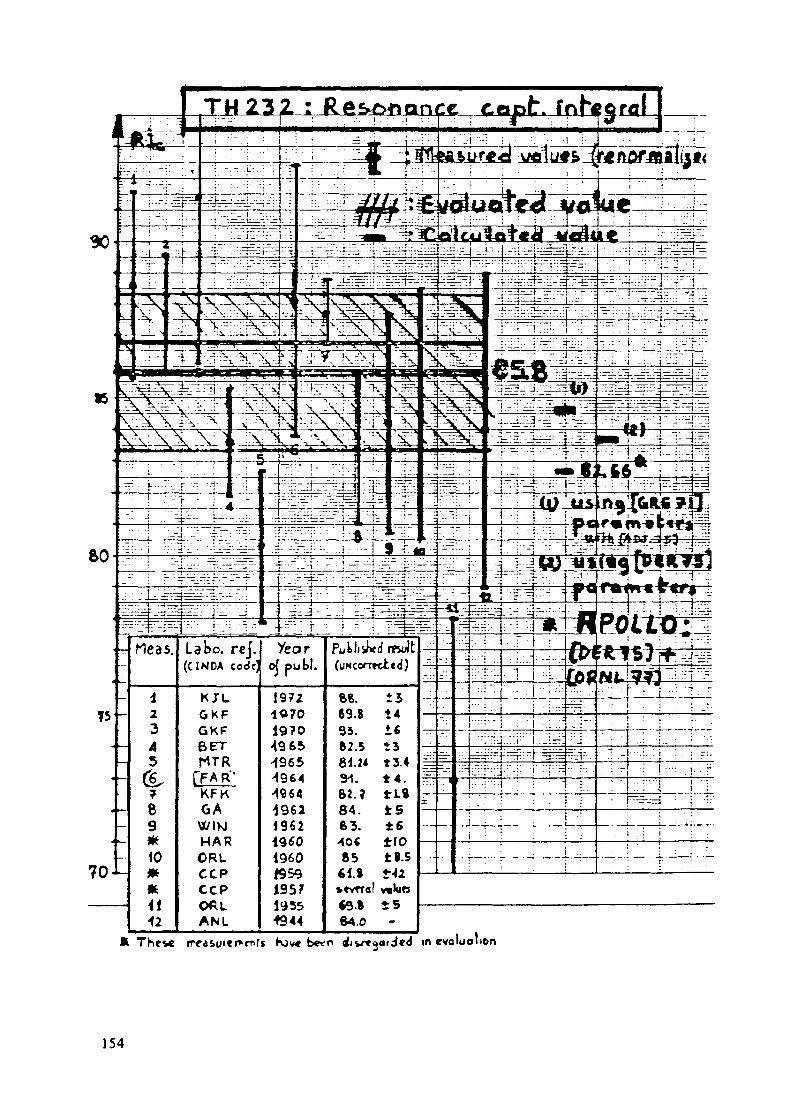
TU 23 2. : Rft&MQnpfc £«jatrv fr^gral
in évolua lion
154

Valu« us*«'in t+>c dfl
«« eocxt•licit »X
155

Th 232 ; C O N C L U S I O N S
•i - Therma I range
• The value oj- C£ (?.4 k) is opporeoHij ^eu
pe di'jcr« poruces, b^iveen ««cf>r«<"«*'*'O<Of« no fT
to Jecrca»« more rapCcM-j tka«a on .1-r r tonar te)
Accurate e x p f r r m e A t a l valuci $KouJo be <ieci'«'<*«'e to oa fc>«ticr krieivPcdqc e>.f the rrgl ^ K a f t cf a0 ( e ) i*> Ik)C t>mc^roJ'urf toe^ . oalcu lorn'
2-Resongnce
are derermfAeo/ \xa'^>'n Tcu.1 p c r c f n
ener
« t^Û is o (o i r lu geoo) atcuracij i f muih t>e( » n p r c v f o ! aocu'n to be e^i-u're i o ' •"* f ac l'or y(a dftadeol mucvh-oaK 'on i'i por^cwlarlLj r e t a rd /or t ti
3 r resonance f rn) )
gy
, It (i in flu's range tliat J u r h K e r (xrorl< r
r desfr
v* HOUJ
eva luabed values jrom etpe^cmfn^a!
156

2.2 ; n u c l c o r data
,.,,.
1i
H5
H3
t45
-13
iMO
^
•>8
n
r«7«
«/
1O RIG IM OF THE" DATA
Remark : no Jo ha a va flat If to takt In^oaccount fcKe f*lj «Xi'eldU^j C/f'^-
. Overall o<Jja*l*\cr\l o^ U k A C A datacr,. ce") —— » c^ift) * -i.o54icr te) —— * c r ^ i É ) * 1.0023
f-Trrv-Jonu-t*- from .ne( |.'S e^ »erne Kem»^»^Cf.'hi-ui/ exprr^cnl-s f f t f D f m . J in R.ntCaiM/Ui»;
. defcu'Jre/ oeljasi"n»fO^ of ukf l f f l ela^abavteJ up«r\ a jcritral rei/ieiv of
£e«MKU : V*»^« «i tV* f,Vjt" one
Cöße ^?6j» ENPF. 6 /JV «iata.
v Tabula (Yon •lloun'ng tot ok î i'nf"o c x c c ^ u n f je'/ ii^>'e!<M'n5
u^NPF/8'Ü.
* Pcvx/ ao ruiiihf n/s o| CNDF/6 12dota in the tHirma! ranoe.
C'6<n«jantifi* o*r'ved ^ror> an anaU\o
Work p u k l i ' i H c J «"• rcj CO •} M« *«y>f)
C^&T^ 73 \)
Thermal va lue r ^KrCr.o2=ievJ
^
55?, 9
5??.o
5? 5. 2.
5?l.o
iJ
°i'
52ft. 5
525.5
isVsli!(A ~"»' "
525.1
[52 V«;
UtH
V»
2.510
*••
2.463
1.498
L^\i
V
»»2.,«
2.285
2.2^?
J.2^
i if'S
t y u rectu<Sfer> of ttt lvalue; -1.5(7*
157

00APOLLO)
- nb . tNOf - t Jî
.'BNL-3Z5 -137i C3]
<£) • ANL- Ju.n71 (DC VOLPl) [11]
0 NM.BTEEN - 1572 ft2]
ENDF-B- d'opr*»

References for U-233 cross sections
111 "APOLLO, Code muHigroupe de résolution oe l 'équation du transportpour les neutrons thermiques et rapides" - A. HOFFMANN et Col.Rapport SERHA "T" N°1193.
[2] "The aldermaston Nuclear Data Library as at May 1963" K. PARKERAWRE Report-0-79/63 - Septembre 1963
[3] BNL-325 : "Neutron cross section" 3ène édition. Volume I - Juin 1973S.F. MUGHABGHAB and C.l GARBER
[4_j "MICROX, a two-region flux spectrum code for the efficient calculationof group cross sections" - by P. Wälti and P. Koch - «apportGulf-GA-A10827 - Avril 1972
Evaluated Nuclear Data Library of Lawrence Livermore LaboratoryBibliothèque ENDL
"Neutron cross section for U-233" USAEC Report GA-7076 - GeneralDyr-anncs, General Atomic Division, Septembre ]%6 - DRAKE
[7] RPI preliminary ENDF/B data March 1967. Weston L.W. (ORNL-TM)
[8J "Interprétation d'expériences critiques homogènes* H. MIKHAÏL,P. REUSS, H. TELLIER, J. YAKUXEEM - Rapport SERHA N°24B "T" -Octobre 1975
ENDF-B/11I : "Evaluated Nuclear Data File" - Version III
IlOj Conférence de Washington de mars 1975. "Neutron cross sections "p. 286 3ème évaluation de H.D. LENMEL (AIEA - Vienne)
[ilJ "Discrepancies and possible adjustements in the 2 200 m/s Fissionparameters" - Rapport ANL-7830 - Juin 1971 - DE VOLPI
[l2J "Revision of the thermal parameters of U-233"Rapport WAPD-TM-1052 (Sept. 1972) - N.M. STEEN
[l3J ENDF-B/IV : 'Evaluated Nuclear Data File" - Version IV
[l4] WCKDL (U.K. Nuclear Data Library) - 1973
159
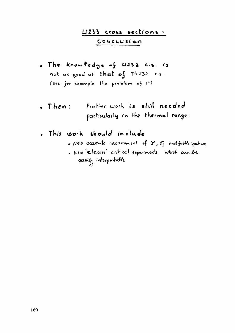
cre»s section* ••CON ecu »(on
The kn0u>fe<j^« •} u z * a c-s . i\not 05 cyjocf as tKafc el Th 232 c.s .
Jor «
Furier uc/ork i» i
fKerma
Thu vï/ork iKou/c/ in c Iw.
160
LIST OF PARTICIPANTS
AUSTRIA
K.L. Lesch
ARGENTINA
H.H. Antunez
Technische Universität Graz (TUG)Alternate Energy PhysicsPetersgasse 16A-8010 Graz
Reactores-C.A. ConstituyentesCNEAAvda. Libertador 82501429 Buenos Aires
AUSTRALIA
P. Bull Permanent Mission of Australiato the IAEAMattiellistrasse 2-4/IIIA-1040 Vienna
BRAZILM. Soares Dias NUCLEBRAS - CDTN
Rua Prof. Mario Werneck s/noPampulna-Cidade Universitaria30000-Belo Horizonte
CHINABo-Rons Bao Shanghai Institute of Nuclear Research
Academia SinicaP.O. Box 8204Shanghai
G. Gambier
D. Greneche
EOF - Service des Combustibles23 bis, Avenue de Messine75384 ParisEDP - Direction des Etudes et RecherchesDépartement Physique des réacteurs1, avenue du Général De Gaule92141 ClamartCEA/CEN de SaclayB.P. 2P-91191 Gif-sur-Yvette
161

GERMANY. F.R.
M. Peehs (Chairman)
B. Zinner
C. Ganguly
Kraftwerk Union AGHamnerbacher Str. 12 + 14Postfach 3220D-8520 ErlangenKernforschungsanlage Jülich GmbHInstitut für chemische Technologieder nuklearen EntsorgungPostfach 1913D-5170 Jülich las above
INDIAB.P. Vanna
K.M. Jayaram
Nuclear Fuel ComplexDepartment of Atomic EnergyHyderabad 500 762Atomic Materials DivisionDepartment of Atomic EnergyBegumpet, Hyderabad 500 016
ITALYT. Candelieri EKEA
S.S. 106 Jonicakm. 419+50075025 Policoro (Matera)
PAKISTAN
S.A. Chaudhri Embassy of PakistanHofzeile 13A-1190 ViennaAustria
USSRM. Slesarev
V. Mukhin
Kurchatov Institute of Atomic PowerMoscowc/o Permanent Mission of USSRto the IAEAWohllebengasse 4A-1040 Vienna, AustriaAll Union Research Instituteof Inorganic MaterialsMoscowc/o Permanent Mission of USSR
162

ORGANIZATIONS
CEC
H. Blank Europäisches Institut für TransuranePostfach 2266D-7500 Karlsruhe
IAEAV. Onufriev (Scientific Secretary)J.L. Zhu (Director, NENF)A.F. NechaevF. SokolovJ. AjuriaM. UgaginF. O'Hara
163