thor power inverters owners manual - carid.com · • potencia inadecuada entregado al inversor o...
TRANSCRIPT
NOTICE OF PROPRIETARY RIGHTSTHIS DOCUMENT CONTAINS PROPRIETARY INFORMATIN. IT MAY NOT BE REPRODUCED OR TRANSFERRED TO DOCUMENTS OR DISCLOSED TO OTHERS OR USED FOR MANUFACTURING OR ANYOTHER PORPUSE WITHOUT PRIOR WRITTEN PERMISSION
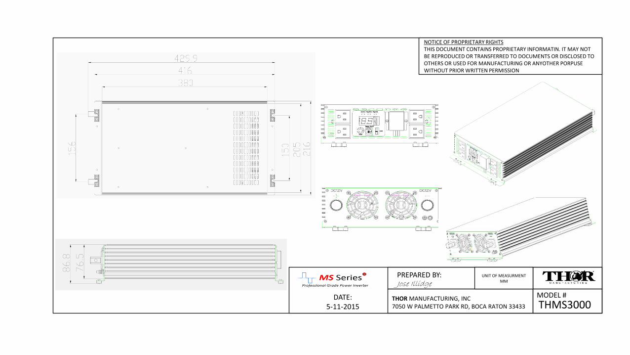
THMS3000MODEL #DATE:
5-11-2015
PREPARED BY:Jose Illidge
THOR MANUFACTURING, INC 7050 W PALMETTO PARK RD, BOCA RATON 33433
UNIT OF MEASURMENTMM
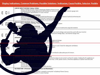
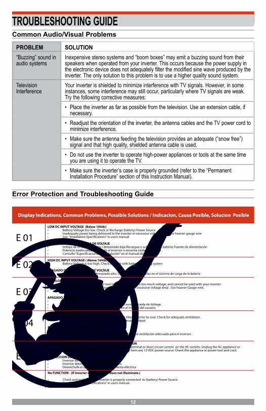
Display Indications, Common Problems, Possible Solutions / Indicacion, Causa Posible, Solucion Posible
LOW DC INPUT VOLTAGE (Below 10Vdc) • Battery Voltage too low, Check or Recharge (battery) Power Source• Inadequate power being delivered to the inverter or excessive voltage drop. Use heavier gauge wire • See “Installation Specifications” in users manual
APAGADO DE BAJA ENTRADA DE VOLTAJE• Voltaje de la fuente (batería ) demasiado baja Recargue o substituya la ( batería) Fuente de alimentación• Potencia inadecuada entregado al inversor o excesiva caída de Voltage .• Consulte “Especificaciones de instalación” en el manual del usuario
HIGH DC INPUT VOLTAGE ( Above 16Vdc)• Battery Voltage is too high, Check for fault with battery charging system
APAGADO DE ALTA ENTRADA DE VOLTAJE• Voltaje de la batería es demasiado alto, Compruebe si hay fallas en el sistema de carga de la batería
OVERLOAD SHUTDOWN • Excessive start-up load. Power tool (or appliance ) draws too much voltage; and cannot be used with your inverter • Inadequate power being delivered to the inverter or excessive voltage drop . Use heavier Gauge wire.• See “Installation Specifications” in users manual.
APAGADO DE SOBRECARGA• Excesivo Carga de arranque.• Potencia inadecuada entregado al inversor o excesiva caída de Voltage .• Consulte “Especificaciones de instalación” en el manual del usuario.
OVER TEMPERATURE • Inverter is too hot (thermal shutdown mode) Allow Inverter to cool. Check for adequate ventilation. • Reduce the load on the inverter to rated continuous output.
APAGADO DE ALTA TEMPERATURA• Inversor está demasiado caliente.• Permita inversor que se enfríe . Compruebe si hay una ventilación adecuada para el inversor .• Reduzca la carga en el inversor .
GROUND FAULT PROTECTION / SHORT CIRCUIT PROTECTION • Inverter senses a leakage current on the ground terminal or short circuit current on the AC sockets. Unplug the AC appliance or
power tool. Turn off the inverter, disconnect unit from any 12 VDC power source. Check the appliance or power tool and cord.
PROTECCION DE FUGA• Inversor detecta una corriente de fuga.• Inversor detecta corriente de cortocircuito.• Desenchufe el aparato de CA o herramienta eléctrica
E 01
E 02
E 03
E 04
E 05
No FUNCTION - (If inverter digital display does not illuminate.)
• Check and make sure the inverter is properly connected to (battery) Power Source .• See “Installation Specifications” in users manual.
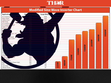
Modified Sine Wave Inverter ChartApplication Operating Wattage Surge Wattage Air Compressor 3 1/4 HPWater HeaterClothes DryerWell PumpAir Compressor 1 HPAir Compressor 3/4 HPImpact Drill 1/2 “Bench Grinder 8”Space HeaterHammer DrillHigh Pressure Washer 1HPKey CutterRefrigerator / FreezerAir Compressor 1/2 HPSump PumpPump MotorGrinder Disk 4 1/2 “Shop VacHand Drill / JigsawFax MachineLaser PrinterMicrowave OvenComputer (Desktop)PrinterSewer Camera & LightsTV’s up to 27”Video MonitorsRecharger - Battery Power ToolsDVDCamcorderCellular Phone
2700450018002238200015001500150015001350100010001200100080080080075075070075060050040030025022520016014050
81005500500055956000450045004200150040503600240036003000160013001200900800
1500150060050040030025022520016014050 22
5W 400W
750W
1000
W
1500
W 2000
W 3000
W 5000
W
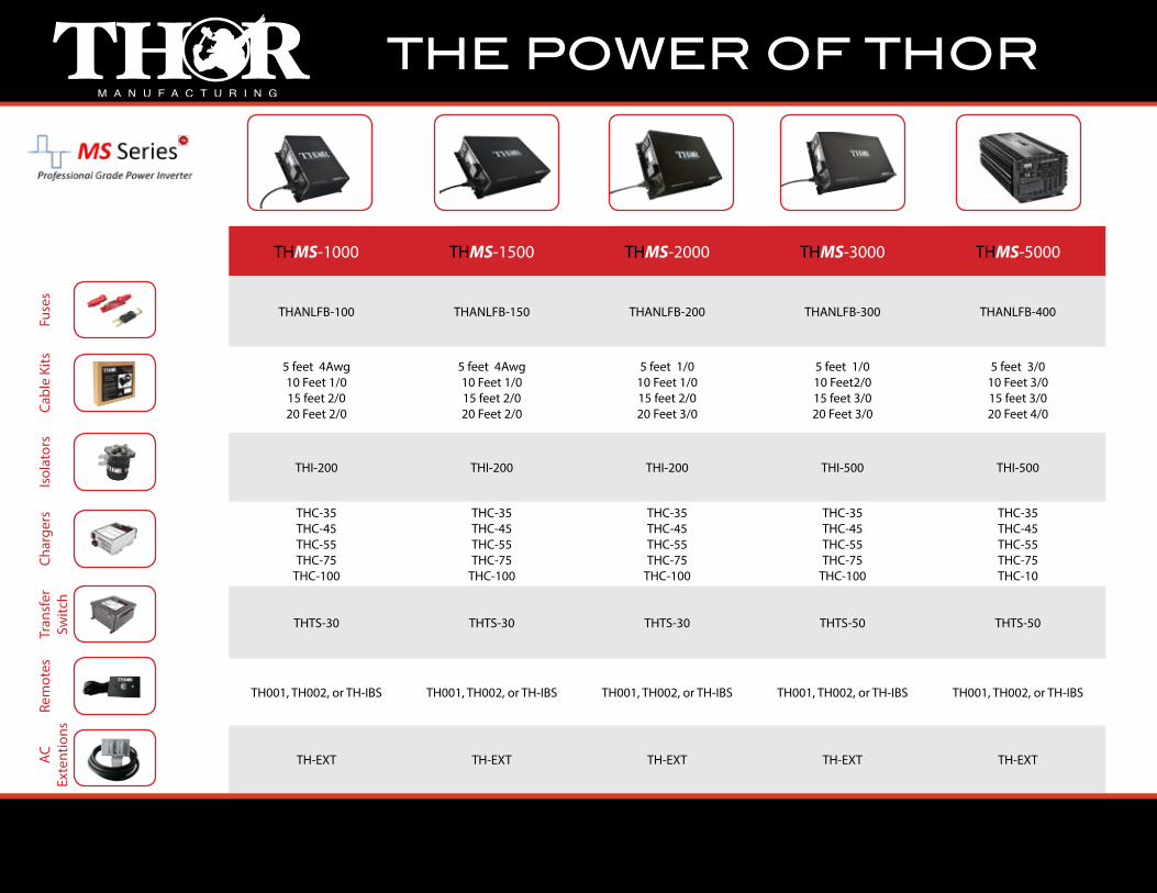
THE POWER OF THORAC
Ex
tent
ions
Rem
otes
Tran
sfer
Switc
hCh
arge
rsIs
olat
ors
Cabl
e Ki
tsFu
ses
THMS-1000 THMS-1500 THMS-2000 THMS-3000 THMS-5000
THANLFB-100 THANLFB-150 THANLFB-200 THANLFB-300 THANLFB-400
5 feet 4Awg 10 Feet 1/015 feet 2/020 Feet 2/0
5 feet 4Awg 10 Feet 1/015 feet 2/020 Feet 2/0
5 feet 1/010 Feet 1/015 feet 2/020 Feet 3/0
5 feet 1/0 10 Feet2/015 feet 3/020 Feet 3/0
5 feet 3/0 10 Feet 3/015 feet 3/020 Feet 4/0
THI-200 THI-200 THI-200 THI-500 THI-500
THC-35THC-45THC-55THC-75
THC-100
THC-35THC-45THC-55THC-75
THC-100
THC-35THC-45THC-55THC-75
THC-100
THC-35THC-45THC-55THC-75
THC-100
THC-35THC-45THC-55THC-75THC-10
THTS-30 THTS-30 THTS-30 THTS-50 THTS-50
TH001, TH002, or TH-IBS TH001, TH002, or TH-IBS TH001, TH002, or TH-IBS TH001, TH002, or TH-IBS TH001, TH002, or TH-IBS
TH-EXT TH-EXT TH-EXT TH-EXT TH-EXT
1
PROFESSIONAL GRADE POWER INVERTER
SAVE THIS INSTRUCTION MANUAL FOR FUTURE REFERENCE. Instruction Manual and Warranty Information
THMS-1000 THMS-1500
THMS-2000 THMS-3000
2
GENERAL SAFETY WARNINGS AND INSTRUCTIONS
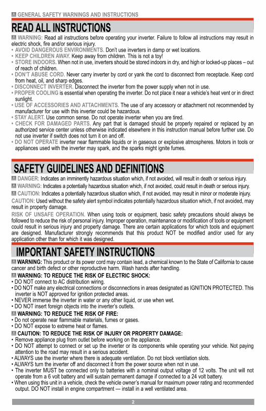
READ ALL INSTRUCTIONS WARNING: Read all instructions before operating your inverter. Failure to follow all instructions may result in
electric shock, fire and/or serious injury.• AVOID DANGEROUS ENVIRONMENTS. Don’t use inverters in damp or wet locations.• KEEP CHILDREN AWAY. Keep away from children. This is not a toy!• STORE INDOORS. When not in use, inverters should be stored indoors in dry, and high or locked-up places – out
of reach of children.• DON’T ABUSE CORD. Never carry inverter by cord or yank the cord to disconnect from receptacle. Keep cord
from heat, oil, and sharp edges.• DISCONNECT INVERTER. Disconnect the inverter from the power supply when not in use.• PROPER COOLING is essential when operating the inverter. Do not place it near a vehicle’s heat vent or in direct
sunlight.• USE OF ACCESSORIES AND ATTACHMENTS. The use of any accessory or attachment not recommended by
manufacturer for use with this inverter could be hazardous.• STAY ALERT. Use common sense. Do not operate inverter when you are tired.• CHECK FOR DAMAGED PARTS. Any part that is damaged should be properly repaired or replaced by an
authorized service center unless otherwise indicated elsewhere in this instruction manual before further use. Donot use inverter if switch does not turn it on and off.
• DO NOT OPERATE inverter near flammable liquids or in gaseous or explosive atmospheres. Motors in tools orappliances used with the inverter may spark, and the sparks might ignite fumes.
SAFETY GUIDELINES AND DEFINITIONS DANGER: Indicates an imminently hazardous situation which, if not avoided, will result in death or serious injury. WARNING: Indicates a potentially hazardous situation which, if not avoided, could result in death or serious injury. CAUTION: Indicates a potentially hazardous situation which, if not avoided, may result in minor or moderate injury.
CAUTION: Used without the safety alert symbol indicates potentially hazardous situation which, if not avoided, may result in property damage.RISK OF UNSAFE OPERATION. When using tools or equipment, basic safety precautions should always be followed to reduce the risk of personal injury. Improper operation, maintenance or modification of tools or equipment could result in serious injury and property damage. There are certain applications for which tools and equipment are designed. Manufacturer strongly recommends that this product NOT be modified and/or used for any application other than for which it was designed.
IMPORTANT SAFETY INSTRUCTIONS WARNING: This product or its power cord may contain lead, a chemical known to the State of California to cause
cancer and birth defect or other reproductive harm. Wash hands after handling. WARNING: TO REDUCE THE RISK OF ELECTRIC SHOCK:
• DO NOT connect to AC distribution wiring.• DO NOT make any electrical connections or disconnections in areas designated as IGNITION PROTECTED. This
inverter is NOT approved for ignition protected areas.• NEVER immerse the inverter in water or any other liquid, or use when wet.• DO NOT insert foreign objects into the inverter’s outlets.
WARNING: TO REDUCE THE RISK OF FIRE:• Do not operate near flammable materials, fumes or gases.• DO NOT expose to extreme heat or flames.
CAUTION: TO REDUCE THE RISK OF INJURY OR PROPERTY DAMAGE:• Remove appliance plug from outlet before working on the appliance.• DO NOT attempt to connect or set up the inverter or its components while operating your vehicle. Not paying
attention to the road may result in a serious accident.• ALWAYS use the inverter where there is adequate ventilation. Do not block ventilation slots.• ALWAYS turn the inverter off and disconnect it from the power source when not in use.• The inverter MUST be connected only to batteries with a nominal output voltage of 12 volts. The unit will not
operate from a 6 volt battery and will sustain permanent damage if connected to a 24 volt battery.• When using this unit in a vehicle, check the vehicle owner’s manual for maximum power rating and recommended
output. DO NOT install in engine compartment — install in a well ventilated area.

3
• DO NOT use with positive ground electrical systems.* Reverse polarity connection will result in a blown fuse andmay cause permanent damage to the inverter and will void warranty.*The majority of modern automobiles, RVs and trucks are negative ground.
• Keep in mind that this inverter may not operate high wattage appliances or equipment that produce heat, such as hair dryers, microwave ovens and toasters.
• Do not open the inverter — there are no user-serviceable parts inside. Opening the inverter will void manufacturer’s warranty.
• Do not use this inverter with medical devices. It is not tested for medical applications.• Install and operate unit only as described in this Instruction Manual.• Check inverter periodically for wear and tear. Return to manufacturer for replacement of worn or defective parts
immediately.Read And Understand This Instruction Manual Before Using This Inverter.
SAVE THESE INSTRUCTIONS WARNING: TO REDUCE THE RISK OF INJURY: FOLLOW THESE INSTRUCTIONS AND THOSE PUBLISHED
BY BATTERY MANUFACTURER AND THE MANUFACTURER OF ANY EQUIPMENT YOU INTEND TO USE WITH THIS UNIT. REVIEW CAUTIONARY MARKINGS ON THESE PRODUCTS AND ON ENGINE.
TABLE OF CONTENTS Introduction . . . . . . . . . . . . . . . . . . . . . . . . . . . . . . . . . . . . . . . . . . . . . . . . . . . . . . . . . . . . . . . . . . . . . . . . . . . . . . . . . . . . . . . . . 3 Features . . . . . . . . . . . . . . . . . . . . . . . . . . . . . . . . . . . . . . . . . . . . . . . . . . . . . . . . . . . . . . . . . . . . . . . . . . . . . . . . . . . . . . . . . . . 4 Controls and Functions. . . . . . . . . . . . . . . . . . . . . . . . . . . . . . . . . . . . . . . . . . . . . . . . . . . . . . . . . . . . . . . . . . . . . . . . . . . . . . . . 4 How These inverters work . . . . . . . . . . . . . . . . . . . . . . . . . . . . . . . . . . . . . . . . . . . . . . . . . . . . . . . . . . . . . . . . . . . . . . . . . . . 5
Power Inverter Output Waveform . . . . . . . . . . . . . . . . . . . . . . . . . . . . . . . . . . . . . . . . . . . . . . . . . . . . . . . . . . . . . . . . . . . . . . 5 Appliance Power Consumption. . . . . . . . . . . . . . . . . . . . . . . . . . . . . . . . . . . . . . . . . . . . . . . . . . . . . . . . . . . . . . . . . . . . . . . . . . 5
Rechargeable Devices . . . . . . . . . . . . . . . . . . . . . . . . . . . . . . . . . . . . . . . . . . . . . . . . . . . . . . . . . . . . . . . . . . . . . . . . . . . . . . 6 Power Source and Protective Features . . . . . . . . . . . . . . . . . . . . . . . . . . . . . . . . . . . . . . . . . . . . . . . . . . . . . . . . . . . . . . . . . . . 6
Power Source Requirements . . . . . . . . . . . . . . . . . . . . . . . . . . . . . . . . . . . . . . . . . . . . . . . . . . . . . . . . . . . . . . . . . . . . . . . . . 6Battery Configuration . . . . . . . . . . . . . . . . . . . . . . . . . . . . . . . . . . . . . . . . . . . . . . . . . . . . . . . . . . . . . . . . . . . . . . . . . . . . . . . 7Determining Battery Size . . . . . . . . . . . . . . . . . . . . . . . . . . . . . . . . . . . . . . . . . . . . . . . . . . . . . . . . . . . . . . . . . . . . . . . . . . . . 7Protective Features. . . . . . . . . . . . . . . . . . . . . . . . . . . . . . . . . . . . . . . . . . . . . . . . . . . . . . . . . . . . . . . . . . . . . . . . . . . . . . . . . 7
Installation . . . . . . . . . . . . . . . . . . . . . . . . . . . . . . . . . . . . . . . . . . . . . . . . . . . . . . . . . . . . . . . . . . . . . . . . . . . . . . . . . . . . . . . . . . 8Operating Environment . . . . . . . . . . . . . . . . . . . . . . . . . . . . . . . . . . . . . . . . . . . . . . . . . . . . . . . . . . . . . . . . . . . . . . . . . . . . . . 8Marine Applications. . . . . . . . . . . . . . . . . . . . . . . . . . . . . . . . . . . . . . . . . . . . . . . . . . . . . . . . . . . . . . . . . . . . . . . . . . . . . . . . . 8Quick Operational Test or Emergency Use . . . . . . . . . . . . . . . . . . . . . . . . . . . . . . . . . . . . . . . . . . . . . . . . . . . . . . . . . . . . . . 8Permanent Installation (Cables and Fuse Not Supplied) . . . . . . . . . . . . . . . . . . . . . . . . . . . . . . . . . . . . . . . . . . . . . . . . . . . . 9Important Cable Information: . . . . . . . . . . . . . . . . . . . . . . . . . . . . . . . . . . . . . . . . . . . . . . . . . . . . . . . . . . . . . . . . . . . . . . . . 10
Operating Instructions. . . . . . . . . . . . . . . . . . . . . . . . . . . . . . . . . . . . . . . . . . . . . . . . . . . . . . . . . . . . . . . . . . . . . . . . . . . . . . . . 11Operation of the 115 Volt AC Outlets . . . . . . . . . . . . . . . . . . . . . . . . . . . . . . . . . . . . . . . . . . . . . . . . . . . . . . . . . . . . . . . . . . 11Operation of the USB Charging Port . . . . . . . . . . . . . . . . . . . . . . . . . . . . . . . . . . . . . . . . . . . . . . . . . . . . . . . . . . . . . . . . . . 11Reading the DC Input Voltage and Output Power Indicators (back of unit) . . . . . . . . . . . . . . . . . . . . . . . . . . . . . . . . . . . . 11Notes on Using the Remote Control (sold separately). . . . . . . . . . . . . . . . . . . . . . . . . . . . . . . . . . . . . . . . . . . . . . . . . . . . . 11
Troubleshooting Guide . . . . . . . . . . . . . . . . . . . . . . . . . . . . . . . . . . . . . . . . . . . . . . . . . . . . . . . . . . . . . . . . . . . . . . . . . . . . . . . 12Common Audio/Visual Problems . . . . . . . . . . . . . . . . . . . . . . . . . . . . . . . . . . . . . . . . . . . . . . . . . . . . . . . . . . . . . . . . . . . . . 12Error Protection and Troubleshooting Guide . . . . . . . . . . . . . . . . . . . . . . . . . . . . . . . . . . . . . . . . . . . . . . . . . . . . . . . . . . . . 12
Care and Maintenance . . . . . . . . . . . . . . . . . . . . . . . . . . . . . . . . . . . . . . . . . . . . . . . . . . . . . . . . . . . . . . . . . . . . . . . . . . . . . . . 13Storage . . . . . . . . . . . . . . . . . . . . . . . . . . . . . . . . . . . . . . . . . . . . . . . . . . . . . . . . . . . . . . . . . . . . . . . . . . . . . . . . . . . . . . . . . 13Fuse Replacement . . . . . . . . . . . . . . . . . . . . . . . . . . . . . . . . . . . . . . . . . . . . . . . . . . . . . . . . . . . . . . . . . . . . . . . . . . . . . . . . 13Preventive Maintenance . . . . . . . . . . . . . . . . . . . . . . . . . . . . . . . . . . . . . . . . . . . . . . . . . . . . . . . . . . . . . . . . . . . . . . . . . . . . 13
Accessories. . . . . . . . . . . . . . . . . . . . . . . . . . . . . . . . . . . . . . . . . . . . . . . . . . . . . . . . . . . . . . . . . . . . . . . . . . . . . . . . . . . . . . 13 Service Information. . . . . . . . . . . . . . . . . . . . . . . . . . . . . . . . . . . . . . . . . . . . . . . . . . . . . . . . . . . . . . . . . . . . . . . . . . . . . . . . 13 Full Two-Year Home Use Warranty . . . . . . . . . . . . . . . . . . . . . . . . . . . . . . . . . . . . . . . . . . . . . . . . . . . . . . . . . . . . . . . . . . . . . 13 Warranty Activation . . . . . . . . . . . . . . . . . . . . . . . . . . . . . . . . . . . . . . . . . . . . . . . . . . . . . . . . . . . . . . . . . . . . . . . . . . . . . . . . . . 14 Specifications . . . . . . . . . . . . . . . . . . . . . . . . . . . . . . . . . . . . . . . . . . . . . . . . . . . . . . . . . . . . . . . . . . . . . . . . . . . . . . . . . . . . . . 15
4
INTRODUCTIONThank you for purchasing this THOR Power Inverter. Please read this Instruction Manual carefully before use to ensure optimum performance and to avoid damage to this product.This power inverter is configured to supply continuous power in the form of 120 volt AC outlets and a USB port to run or recharge most household or electronic appliances.
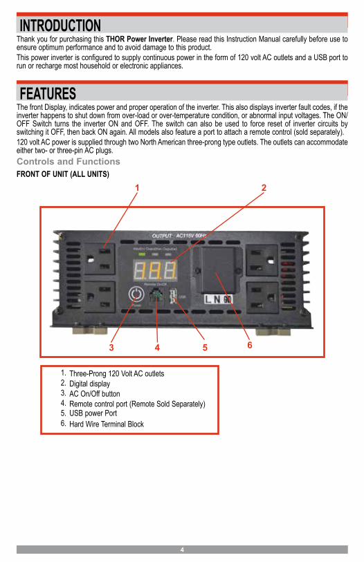
FEATURESThe front Display, indicates power and proper operation of the inverter. This also displays inverter fault codes, if the inverter happens to shut down from over-load or over-temperature condition, or abnormal input voltages. The ON/OFF Switch turns the inverter ON and OFF. The switch can also be used to force reset of inverter circuits by switching it OFF, then back ON again. All models also feature a port to attach a remote control (sold separately).120 volt AC power is supplied through two North American three-prong type outlets. The outlets can accommodate either two- or three-pin AC plugs.Controls and FunctionsFRONT OF UNIT (ALL UNITS)
1 2
3 4 5
1. Three-Prong 120 Volt AC outlets2. Digital display3. AC On/Off button4. Remote control port (Remote Sold Separately)5. USB power Port6. Hard Wire Terminal Block
6
5
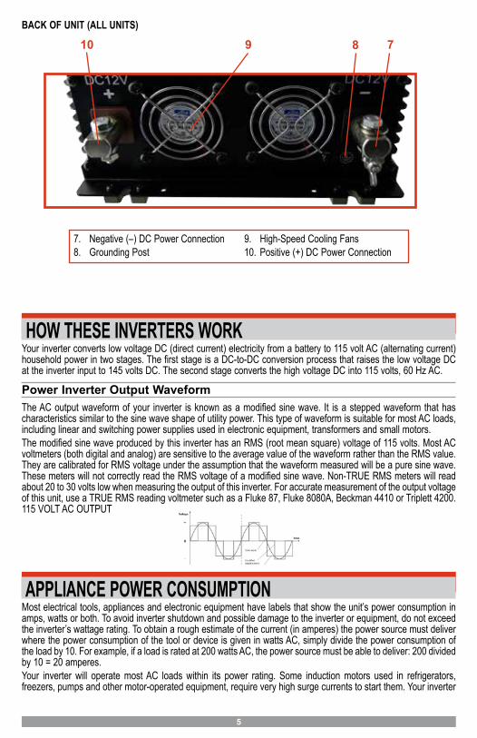
BACK OF UNIT (ALL UNITS)
7. Negative (–) DC Power Connection8. Grounding Post
9. High-Speed Cooling Fans10. Positive (+) DC Power Connection
10 89 7
HOW THESE INVERTERS WORKYour inverter converts low voltage DC (direct current) electricity from a battery to 115 volt AC (alternating current) household power in two stages. The first stage is a DC-to-DC conversion process that raises the low voltage DC at the inverter input to 145 volts DC. The second stage converts the high voltage DC into 115 volts, 60 Hz AC.
Power Inverter Output WaveformThe AC output waveform of your inverter is known as a modified sine wave. It is a stepped waveform that has characteristics similar to the sine wave shape of utility power. This type of waveform is suitable for most AC loads, including linear and switching power supplies used in electronic equipment, transformers and small motors.The modified sine wave produced by this inverter has an RMS (root mean square) voltage of 115 volts. Most AC voltmeters (both digital and analog) are sensitive to the average value of the waveform rather than the RMS value. They are calibrated for RMS voltage under the assumption that the waveform measured will be a pure sine wave. These meters will not correctly read the RMS voltage of a modified sine wave. Non-TRUE RMS meters will read about 20 to 30 volts low when measuring the output of this inverter. For accurate measurement of the output voltage of this unit, use a TRUE RMS reading voltmeter such as a Fluke 87, Fluke 8080A, Beckman 4410 or Triplett 4200. 115 VOLT AC OUTPUT
APPLIANCE POWER CONSUMPTIONMost electrical tools, appliances and electronic equipment have labels that show the unit’s power consumption in amps, watts or both. To avoid inverter shutdown and possible damage to the inverter or equipment, do not exceed the inverter’s wattage rating. To obtain a rough estimate of the current (in amperes) the power source must deliver where the power consumption of the tool or device is given in watts AC, simply divide the power consumption of the load by 10. For example, if a load is rated at 200 watts AC, the power source must be able to deliver: 200 divided by 10 = 20 amperes.Your inverter will operate most AC loads within its power rating. Some induction motors used in refrigerators, freezers, pumps and other motor-operated equipment, require very high surge currents to start them. Your inverter
6
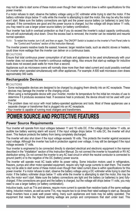
may not be able to start some of these motors even though their rated current draw is within specifications for this power inverter.If a motor refuses to start, observe the battery voltage using a DC voltmeter while trying to start the motor. If the battery voltmeter drops below 11 volts while the inverter is attempting to start the motor, this may be why the motor won’t start. Make sure the battery connections are tight and the power source battery (or batteries) is (are) fully-charged. If the connections are good and the power source is charged, but the voltage still drops below 11 volts, you may need to use a larger power source battery (or battery combination).Your inverter has built-in overload protection so that if you do exceed the inverter’s output capacity continuously, the unit will automatically shut down. Once the excess load is removed, the inverter can be restarted and resume normal operation.Note: To restart the inverter, turn it off, and then on again. The ON/OFF Switch is located on the inverter’s Front Panel (refer to
the “Control and Functions” section of this Instruction Manual).The inverter powers resistive loads the easiest; however, larger resistive loads, such as electric stoves or heaters, could draw more wattage than the inverter can deliver on a continuous basis.
CAUTIONSEnsure that total continuous power consumption of all tools and appliances to be used simultaneously with your inverter does not exceed the inverter’s continuous wattage rating. Also ensure that start-up wattage for inductive loads does not exceed peak watts for more than a second.Appliances such as microwave ovens will normally draw more than their rated current and could possibly overload the inverter when operated simultaneously with other appliances. For example: A 600 watt microwave oven draws approximately 940 watts.
Rechargeable Devices CAUTIONS
• Some rechargeable devices are designed to be charged by plugging them directly into an AC receptacle. Thesedevices may damage the inverter or the charging circuit.
• When using a rechargeable device with your inverter, monitor its temperature for the initial ten minutes of use todetermine if it produces excessive heat. If excessive heat is produced, the device should not be used with yourinverter.
• This problem does not occur with most battery-operated appliances and tools. Most of these appliances use aseparate charger or transformer that is plugged into an AC receptacle.
• Your inverter is capable of running most chargers and transformers.
POWER SOURCE AND PROTECTIVE FEATURESPower Source RequirementsYour inverter will operate from input voltages between 11 and 16 volts DC. If the voltage drops below 11 volts, an audible low battery warning alarm will sound. If the input voltage drops below 10 volts DC, the inverter will shut down. This feature protects the battery from being completely discharged.The inverter will also shut down if the input voltage exceeds 16 volts. This protects the inverter against excessive input voltage. Although the inverter has built-in protection against over voltage, it may still be damaged if the input voltage exceeds 17 volts.Your inverter is engineered to be connected directly to standard electrical and electronic equipment in the manner described in the “Installation” section of this Instruction Manual. Do not connect the inverter to household or RV AC distribution wiring. Do not connect the inverter to any AC load circuit in which the neutral conductor is connected to ground (earth) or to the negative of the DC (battery) power source.The inverter will operate most AC loads within its power rating. Some induction motors used in refrigerators, freezers, pumps and other motor-operated equipment, require very high surge currents to start them. The inverter may not be able to start some of these motors even though their rated current draw is within specifications for this power inverter. If a motor refuses to start, observe the battery voltage using a DC voltmeter while trying to start the motor. If the battery voltmeter drops below 11 volts while the inverter is attempting to start the motor, this may be why the motor won’t start. Make sure the battery connections are tight and the battery (or batteries) is (are) fully-charged. If the connections are good and the battery is charged, but the voltage still drops below 11 volts, you may need to use a larger battery (or battery combination).Inductive loads, such as TVs and stereos, require more current to operate than resistive loads of the same wattage rating. Induction motors, as well as some TVs, may require two to six times their rated wattage to start up. Because these inverters have a peak watt power rating, many such appliances and tools may be safely operated. The equipment that needs the highest starting wattage are pumps and compressors that start under load. This
7
equipment can be safely tested. If an overload is detected, the inverter will simply shut down until the overload situation is corrected.
CAUTIONS• Exceeding recommended voltage limits will void manufacturer’s warranty.• NEVER try to use your inverter with any 12 volt DC power source that uses a positive ground. (Most vehicles and
boats use negative ground systems.)• The Power Inverter must be connected only to batteries with a nominal output voltage of 12 volts. The unit will not
operate from a 6 volt battery and will sustain permanent damage if connected to a 24 volt battery.• Reverse polarity connection will result in a blown fuse and may cause permanent damage to the inverter.
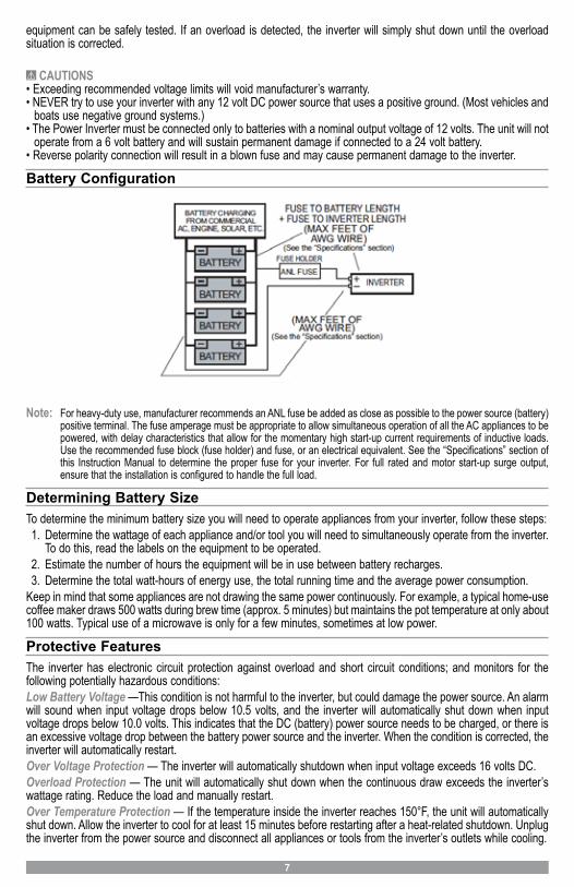
Battery Configuration
Note: For heavy-duty use, manufacturer recommends an ANL fuse be added as close as possible to the power source (battery) positive terminal. The fuse amperage must be appropriate to allow simultaneous operation of all the AC appliances to be powered, with delay characteristics that allow for the momentary high start-up current requirements of inductive loads. Use the recommended fuse block (fuse holder) and fuse, or an electrical equivalent. See the “Specifications” section of this Instruction Manual to determine the proper fuse for your inverter. For full rated and motor start-up surge output, ensure that the installation is configured to handle the full load.
Determining Battery SizeTo determine the minimum battery size you will need to operate appliances from your inverter, follow these steps:1. Determine the wattage of each appliance and/or tool you will need to simultaneously operate from the inverter.
To do this, read the labels on the equipment to be operated.2. Estimate the number of hours the equipment will be in use between battery recharges.3. Determine the total watt-hours of energy use, the total running time and the average power consumption.
Keep in mind that some appliances are not drawing the same power continuously. For example, a typical home-use coffee maker draws 500 watts during brew time (approx. 5 minutes) but maintains the pot temperature at only about 100 watts. Typical use of a microwave is only for a few minutes, sometimes at low power.
Protective FeaturesThe inverter has electronic circuit protection against overload and short circuit conditions; and monitors for the following potentially hazardous conditions:Low Battery Voltage —This condition is not harmful to the inverter, but could damage the power source. An alarm will sound when input voltage drops below 10.5 volts, and the inverter will automatically shut down when input voltage drops below 10.0 volts. This indicates that the DC (battery) power source needs to be charged, or there is an excessive voltage drop between the battery power source and the inverter. When the condition is corrected, the inverter will automatically restart.Over Voltage Protection — The inverter will automatically shutdown when input voltage exceeds 16 volts DC.Overload Protection — The unit will automatically shut down when the continuous draw exceeds the inverter’s wattage rating. Reduce the load and manually restart.Over Temperature Protection — If the temperature inside the inverter reaches 150°F, the unit will automatically shut down. Allow the inverter to cool for at least 15 minutes before restarting after a heat-related shutdown. Unplug the inverter from the power source and disconnect all appliances or tools from the inverter’s outlets while cooling.
8
If the Digital display, displays a fault code follow the steps outlined in the “Troubleshooting” section of this Instruction Manual. The Fault LED will light if there is an excessive voltage drop between the (battery) power source and the inverter.Note: Reverse polarity or short circuit condition may cause external or internal fuses to open and may cause irreversible
damage to the Power Inverter. Take extra care to ensure a proper polarity hook-up. CAUTION
• If turning the ON/OFF Switch off, then on again does not reset the inverter, DO NOT ATTEMPT TO OPEN THEINVERTER. Opening the inverter for any reason will void the warranty. The unit must be returned to manufacturer for testing and repair by professional factory technicians.
INSTALLATIONYour inverter will provide you with continuous electrical power when powered by a reliable 12 volt DC source, such as a vehicle battery or a multiple battery configuration. This manual does not describe all of the possible configurations.
Operating EnvironmentFor best operating results, your inverter should be placed on a flat surface, such as the ground, car floor or seat or other solid surface to help diffuse the heat that is generated. Position the inverter as close to the DC power source as possible.The inverter should only be operated in locations that meet the following criteria:DRY – Do not allow water and/or other liquids to come into contact with the inverter.COOL – Ambient air temperature should be between 30°F (–1°C) non-condensing and 105°F (40°C). Do not place the inverter on or near a heating vent or any piece of equipment that is generating heat above room temperature. Keep the inverter out of direct sunlight.VENTILATED – Allow at least three inches of clearance from other objects to ensure free air circulation around the inverter. Never place items on or over the inverter during operation.SAFE – Do not locate inverters in an area, room or compartment where explosives or flammable fumes might be present, such as engine rooms, engine compartments and boats or small, unvented battery compartments.
Marine ApplicationsIn all marine applications, DO NOT install the inverter below or near the waterline; and keep the inverter away from moisture and water.Use ONLY non-corrosive marine fasteners and fittings for installation. Only connect the inverter’s DC input to existing wiring (that has been approved for marine use) at the appropriate gauge, cable and length. The cable, fuse holder and fuse (not supplied) can be purchased at an electrical supply company. Call the manufacturer for additional installation information.
Quick Operational Test or Emergency UseYou will need:• A heavy-duty jumper cable set of the specified AWG wire rating (refer to the “Specifications” section of this
Instruction Manual)• A fully-charged automobile battery• A common slip joint plier for loosening and tightening terminal nutsPROCEDURE1. Unscrew nuts in input terminal block.2. Identify the positive and negative terminals on the 12 volt DC battery (or other 12 volt DC power source) and
identify the positive and negative terminals on the inverter.3. Using a set of heavy-duty jumper cables, attach the red cable to the inverter’s positive (+) terminal and the black
cable to the inverter’s negative (–) terminal.4. Connect the clamps on the other ends of the jumper cables to the corresponding positive (+) and negative (–)
terminals on the 12 volt DC vehicle battery (or other 12 volt DC power source). There may be some minorsparking.
5. Turn the inverter ON/OFF Switch on.6. Plug in a lamp with a 100 watt light bulb and switch the lamp on. If the lamp works normally, the inverter is
functioning properly and you can proceed to a permanent installation or continue to use the inverter with lowwattage appliances. If the lamp does not light or does not work correctly:
9
A. Check all connections and tighten any that may be loose.B. Ensure that the source battery has adequate charge.C. If steps A and B do not correct the problem, refer to the “Service Information” section of this Instruction
Manual for assistance.
Permanent Installation (Cables and Fuse Not Supplied)For permanent installation to heavy-duty battery power you will need:• Two cables (as indicated in the “Specifications” section of this Instruction Manual)• Terminals to fit cable ends and stud terminals to inverter• Hardware and battery connector to connect cables to the battery bank• A single length of AWG cable multi-stranded, flexible, insulated cable (as indicated in the “Specifications” section
of this Instruction Manual) for chasis ground connection when using inverter in a household application.• A holder and fuse (see the “Specifications” section of this Instruction Manual)• Mounting screws, bolts and nuts for mounting the inverter and fuse holder• A drill for mounting the inverter and fuse holder• Lead-tin solder, flux, propane torch and an igniter for the torch• Wire stripper/cutting toolPRELIMINARY STEPSThe inverter has four slots in its mounting bracket that allow the unit to be fastened against a bulkhead, floor, wall or other flat surface. Ideally, the mounting surface should be cool to the touch. It is more efficient to use longer AC wiring than DC wiring, so install the inverter as close as possible to the 12 volt DC power source.The inverter should be operated in horizontal position; if it is to be mounted on a wall, mount it horizontally so that indicators, switches, outlets and terminal blocks on the front panel are visible and accessible.1. If inverter is to be installed in a vehicle, manufacturer recommends that it be shock mounted to either the floor
(in a clear, safe area) or on a secure flat surface.2. Locate a convenient place to mount the inverter and fuse holder.3. Perform a test routing of the proposed cable length, but don’t do any cutting at this time (refer to the diagram
in the “Battery Configuration” section of this Instruction Manual).4. Using an appropriate AWG cable (refer to the “Specifications” section of this Instruction Manual), reposition the
inverter and fuse holder if necessary.5. After you have performed the above preliminary installation steps, proceed with the actual inverter installation.
Contact the manufacturer for any further installation information or questions.
PERMANENT INSTALLATION PROCEDUREThe cables between the power source and inverter should be set up as illustrated in the diagram in the “Battery Configuration” section of this Instruction Manual. Unscrew terminal nuts before beginning permanent installation. Proceed with DC cable and fuse installation as follows:1. Ensure the inverter’s ON/OFF Power Switch is in the off position.2. Using tools and hardware, mount the inverter to a flat, stable surface.3. Ensure that mounting hardware does not touch any fuse holder or fuse contacts. Select an appropriate fuse
(refer to the “Specifications” section of this Instruction Manual) and ensure that the fuse is removed from itsholder.
4. Select appropriate cable (refer to the “Specifications” section of this Instruction Manual). Measure the cabletwice before cutting.
5. Cut one cable length to connect the negative (–) battery terminal to the inverter’s negative terminal, leaving alittle slack in the cable.
6. Cut another cable to connect the positive (+) battery terminal to one side of fuse holder, leaving a little slack.7. Cut the final cable to connect the other side of fuse holder to the inverter’s positive (+) terminal.8. Strip the end insulation of all three cables to 1-inch (2.45 cm).9. Sweat-solder end of all cables. For safety, do this in an open space because it may require the use of a propane
torch.10. Connect one end of the negative (–) cable to a ring terminal* going to the battery(ies).11. Connect the short end of the positive (+) cable to a ring terminal* going to the battery(ies).12. Crimp or clamp ring terminals of the negative (–) and positive (+) cables (going to the battery), but do not
connect to the battery yet.
10
13. Connect the stripped, soldered (longer) end of the positive (+) cable to the red stud marked (+) on the inverterand tighten the retaining nut.
14. Connect the stripped, soldered end of the negative (–) cable to the black stud marked (–) on the inverter andtighten the retaining nut.
15. Connect the other (long) end of the (+) positive cable to one terminal of the heavy-duty fuse holder.16. Connect the other conductor of the heavy-duty fuse holder to the (short) positive (+) battery terminal.17. Connect the other end of the (–) negative cablewith the ring terminal to the negative (–) battery terminal.18. Connect an appropriate insulated wire (refer to the “Specifications” section of this Instruction Manual) between
the chassis grounding screw on the inverter’s case and a solid electrical ground to minimize possible electricalnoise in TV and radio reception. Do not connect this wire to the negative DC input terminal.
19. Ensure that all electrical connections have been tightened.20. Insert the fuse into the fuse holder. There may be some sparking.21. Ensure the 12 volt DC power source has an adequate charge.22. Turn the inverter on and apply a test load to the 120 volt AC outlets.* Ring terminals are not included and must be supplied by user. If, after following all of the above steps, the inverter does not perform properly, the source voltage may be too low or the cables may be too long (or the gauge too light). Having checked and corrected these conditions, if necessary, refer to the “Service Information” section of this Instruction Manual for assistance if problems persist.
CAUTION• Loose connectors may cause overheated wires and melted insulation.• Check to make sure you have not reversed the polarity. Damage due to reversed polarity is not covered by
manufacturer’s warranty.
IMPORTANT CABLE INFORMATION:Substantial power loss and reduced battery operating time results from inverters installed with cables that are not able to supply full power. Symptoms of low battery power can result from cables that are either excessively long or an insufficient gauge. Marine installations are also subjected to vibration and stresses that exceed those of other mobile installations. Therefore, the installer/operator should be especially aware of the requirements to maintain secure, tight, water-resistant electrical connections and to provide for strain relief for DC cables and appliance wiring. Cable insulation must be the appropriate type for the environment.
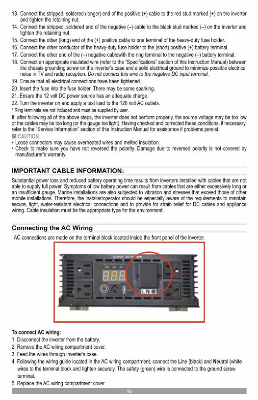
Connecting the AC Wiring AC connections are made on the terminal block located inside the front panel of the inverter.
To connect AC wiring:1. Disconnect the inverter from the battery.2. Remove the AC wiring compartment cover.3. Feed the wires through inverter’s case.4. Following the wiring guide located in the AC wiring compartment, connect the Line (black) and Neutral (white
wires to the terminal block and tighten securely. The safety (green) wire is connected to the ground screwterminal.
5. Replace the AC wiring compartment cover.
11
OPERATING INSTRUCTIONS CAUTION: Make sure the combined load requirement of your equipment does not exceed your inverter’s
maximum continuous power.
Operation of the 120 Volt AC OutletsThis unit features four 115 volt AC GFCI (ground fault circuit interrupter) protected outlets, that function in the same way as GFCI outlets you would typically use in your home. GFCI outlets are intended to protect equipment by interrupting the circuit if current leakage exceeds 30 mA of current within 25 milliseconds.1. Connect the inverter to a functioning 12 volt DC power source as described in this Instruction Manual. Make
sure there is adequate space for proper ventilation of the inverter.2. Press the Power Pushbutton to turn the unit ON.3. The Power/Fault LED display will light green, indicating a proper connection. If the Power/Fault LED Indicator
lights red, indicating a fault condition exists, refer to the “Troubleshooting” section of this Instruction Manual.4. Plug the (110/120 volt AC) appliance into one of the Inverter’s three-prong AC outlets and operate normally.
Note: The Inverter will not operate appliances and equipment that generate heat, such as hair dryers, electric blankets,microwave ovens and toasters.Remember to disconnect the inverter from any power source when not in use.
Operation of the USB Charging Port1. Connect the inverter to a functioning 12 volt DC power source as described in this Instruction Manual. Make
sure there is adequate space for proper ventilation of the inverter.2. Press the Power Pushbutton to turn the unit ON.3. The display will light up , indicating a proper connection. If the display, displays a fault code, indicating a fault
condition exists, refer to the “Troubleshooting” section of this Instruction Manual.4. Plug the USB-powered device into the inverter’s USB Charging Port and operate normally.
Note: This unit’s USB Charging Port does not support data communication. It only provides 2.1 Amps 5Volts DC power to anexternal USB-powered device.Remember to disconnect the inverter from any power source when not in use.
Notes on Using the Remote Control (sold separately)The manufacturer offers (as a separate item) a Remote Control specifically designed for this line of inverters. The inverter On/Off Switch must be in the off position when connecting the Remote Control to the unit, or the Remote Control will not operate. Once the unit has been turned on using the Remote Control, inverter operation will continue to be controlled through the Remote Control. Turn the inverter off before disconnecting the Remote Control. For more information about attaching and using the Remote Control, please refer to the Remote Control Instruction Manual.
12
TROUBLESHOOTING GUIDECommon Audio/Visual Problems
PROBLEM SOLUTION“Buzzing” sound in audio systems
Inexpensive stereo systems and “boom boxes” may emit a buzzing sound from their speakers when operated from your inverter. This occurs because the power supply in the electronic device does not adequately filter the modified sine wave produced by the inverter. The only solution to this problem is to use a higher quality sound system.
Television Interference
Your inverter is shielded to minimize interference with TV signals. However, in some instances, some interference may still occur, particularly where TV signals are weak. Try the following corrective measures:• Place the inverter as far as possible from the television. Use an extension cable, if
necessary.• Readjust the orientation of the inverter, the antenna cables and the TV power cord to
minimize interference.• Make sure the antenna feeding the television provides an adequate (“snow free”)
signal and that high quality, shielded antenna cable is used.• Do not use the inverter to operate high-power appliances or tools at the same time
you are using it to operate the TV.• Make sure the inverter’s case is properly grounded (refer to the “Permanent
Installation Procedure” section of this Instruction Manual).
Error Protection and Troubleshooting Guide
Display Indications, Common Problems, Possible Solutions / Indicacion, Causa Posible, Solucion Posible
LOW DC INPUT VOLTAGE (Below 10Vdc) • Battery Voltage too low, Check or Recharge (battery) Power Source• Inadequate power being delivered to the inverter or excessive voltage drop. Use heavier gauge wire • See “Installation Speci� cations” in users manual
APAGADO DE BAJA ENTRADA DE VOLTAJE• Voltaje de la fuente (batería ) demasiado baja Recargue o substituya la ( batería) Fuente de alimentación• Potencia inadecuada entregado al inversor o excesiva caída de Voltage .• Consulte “Especi� caciones de instalación” en el manual del usuario
HIGH DC INPUT VOLTAGE ( Above 16Vdc)• Battery Voltage is too high, Check for fault with battery charging system
APAGADO DE ALTA ENTRADA DE VOLTAJE• Voltaje de la batería es demasiado alto, Compruebe si hay fallas en el sistema de carga de la batería
OVERLOAD SHUTDOWN • Excessive start-up load. Power tool (or appliance ) draws too much voltage; and cannot be used with your inverter • Inadequate power being delivered to the inverter or excessive voltage drop . Use heavier Gauge wire.• See “Installation Speci� cations” in users manual.
APAGADO DE SOBRECARGA• Excesivo Carga de arranque.• Potencia inadecuada entregado al inversor o excesiva caída de Voltage .• Consulte “Especi� caciones de instalación” en el manual del usuario.
OVER TEMPERATURE • Inverter is too hot (thermal shutdown mode) Allow Inverter to cool. Check for adequate ventilation. • Reduce the load on the inverter to rated continuous output.
APAGADO DE ALTA TEMPERATURA• Inversor está demasiado caliente.• Permita inversor que se enfríe . Compruebe si hay una ventilación adecuada para el inversor .• Reduzca la carga en el inversor .
GROUND FAULT PROTECTION / SHORT CIRCUIT PROTECTION • Inverter senses a leakage current on the ground terminal or short circuit current on the AC sockets. Unplug the AC appliance or
power tool. Turn o� the inverter, disconnect unit from any 12 VDC power source. Check the appliance or power tool and cord.
PROTECCION DE FUGA• Inversor detecta una corriente de fuga.• Inversor detecta corriente de cortocircuito.• Desenchufe el aparato de CA o herramienta eléctrica
E 01
E 02
E 03
E 04
E 05No FUNCTION - (If inverter digital display does not illuminate.)
• Check and make sure the inverter is properly connected to (battery) Power Source .• See “Installation Speci� cations” in users manual.
Resetting the InverterAfter over-voltage or thermal automatic shutdown, your inverter will reset automatically. CARE AND MAINTENANCStorage1. Ideal storage temperature range is 50-68°F (10-20°C).2. Store and use the inverter in a cool, dry place with adequate ventilation.3. Avoid locations that are exposed to heating units, radiators, direct sunlight or excessive humidity or dampness
.
Fuse ReplacementYour inverter is equipped with multiple internal fuses. Normally, these fuses will not “blow” unless there is a serious problem inside the unit. Internal fuses are replaceable; however, only trained personnel should attempt fuse replacement. Refer to the “Service Information” section of this Instruction Manual.
Preventive MaintenanceInverters require minimal maintenance. For optimum performance, the manufacturer recommends periodically performing the following preventive maintenance.1. Turn the inverter off using the front panel On/Off Switch.2. Check and tighten all electrical connections, including the ground.3. Using a non-metallic vacuum cleaner hose, vacuum the air slots and fan area.4. Clean the outside of the unit using a damp (not wet) cloth.5. Wipe unit surfaces thoroughly with a dry cloth.6. Resume operation.
RETURN / REPAIR POLICYDefective products, other than accessories, may be returned postage prepaid to THOR POWER PRODUCTS. Any defective product, other than accessories, that is returned to THOR POWER PRODUCTS within 30 days of the date of purchase will be replaced free of charge. If such a product is returned more than 30 days but less than two year from the purchase date, THOR POWER PRODUCTS will repair the unit or, at its option, replace it free of charge. If the unit is repaired, new or reconditioned replacement parts may be used, at THOR POWER RPODUCTS option. A unit may be replaced with a new or reconditioned unit of the same or comparable design. The repaired or replaced unit will then be warranted under the terms of the remainder of the warranty period. The customer is responsible for the shipping charges on all returned. During the warranty period, THOR POWER PRODUCTS. will be responsible for the return shipping charges.
WARRANTY ACTIVATION: Please complete the Warranty Activation Card and mail to THOR Manufacturing. Enter the model number and product type and serial number. All THOR Manufacturing products must be registered within 30 days of purchase to activate this warranty. Mail the completed registration form, along with a copy of the original sales receipt to: THOR Manufacturing, 7050 W. Palmetto Park Rd., Suite 4, Boca Raton, FL 33433.
SPECIFICATIONS
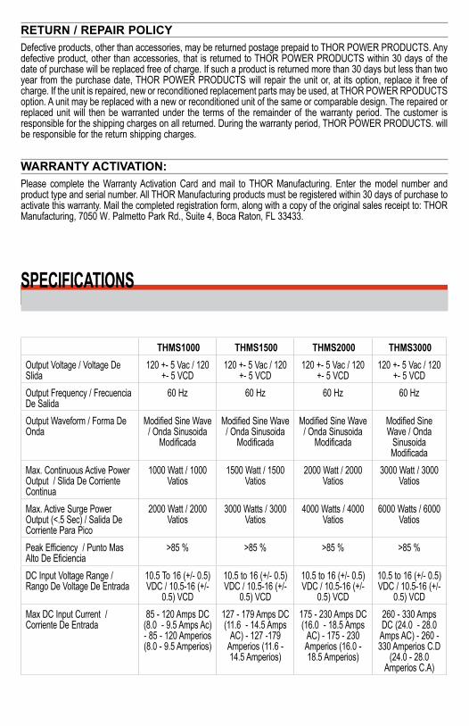
SPECIFICATIONSTHMS1000 THMS1500 THMS2000 THMS3000
Output Voltage / Voltage De Slida
120 +- 5 Vac / 120 +- 5 VCD
120 +- 5 Vac / 120 +- 5 VCD
120 +- 5 Vac / 120 +- 5 VCD
120 +- 5 Vac / 120 +- 5 VCD
Output Frequency / Frecuencia De Salida
60 Hz 60 Hz 60 Hz 60 Hz
Output Waveform / Forma De Onda
Modified Sine Wave / Onda Sinusoida
Modificada
Modified Sine Wave / Onda Sinusoida
Modificada
Modified Sine Wave / Onda Sinusoida
Modificada
Modified Sine Wave / Onda
Sinusoida Modificada
Max. Continuous Active Power Output / Slida De Corriente Continua
1000 Watt / 1000 Vatios
1500 Watt / 1500 Vatios
2000 Watt / 2000 Vatios
3000 Watt / 3000 Vatios
Max. Active Surge Power Output (<.5 Sec) / Salida De Corriente Para Pico
2000 Watt / 2000 Vatios
3000 Watts / 3000 Vatios
4000 Watts / 4000 Vatios
6000 Watts / 6000 Vatios
Peak Efficiency / Punto Mas Alto De Eficiencia
>85 % >85 % >85 % >85 %
DC Input Voltage Range / Rango De Voltage De Entrada
10.5 To 16 (+/- 0.5) VDC / 10.5-16 (+/-
0.5) VCD
10.5 to 16 (+/- 0.5) VDC / 10.5-16 (+/-
0.5) VCD
10.5 to 16 (+/- 0.5) VDC / 10.5-16 (+/-
0.5) VCD
10.5 to 16 (+/- 0.5) VDC / 10.5-16 (+/-
0.5) VCDMax DC Input Current / Corriente De Entrada
85 - 120 Amps DC (8.0 - 9.5 Amps Ac) - 85 - 120 Amperios (8.0 - 9.5 Amperios)
127 - 179 Amps DC (11.6 - 14.5 Amps
AC) - 127 -179 Amperios (11.6 - 14.5 Amperios)
175 - 230 Amps DC (16.0 - 18.5 Amps
AC) - 175 - 230 Amperios (16.0 - 18.5 Amperios)
260 - 330 Amps DC (24.0 - 28.0 Amps AC) - 260 - 330 Amperios C.D
(24.0 - 28.0 Amperios C.A)