this thesis is dedicated to my parents - universidade do … · this thesis is dedicated to my...
TRANSCRIPT

This thesis is dedicated to my parents for their love, endless support
and encouragement.

v
ABSTRACT
The objective of this research work was to study the degradation (corrosion and
tribocorrosion) resulting from mechanical (wear) and electrochemistry (corrosion)
interactions in Al/Al3Ti and Al/Al3Zr functionally graded materials (FGMs). The
influence of the spatial distribution of the platelets on the corrosion and tribocorrosion
behaviour was evaluated. The Al/Al3Ti and Al/Al3Zr FGMs were produced by
centrifugal casting, originating samples in the form of rings that presented radial
gradients of the reinforcements.
The corrosion resistance of Al/Al3Ti and Al/Al3Zr FGMs was studied using
electrochemical techniques namely, open circuit potential (OCP), potenciodynamic
polarization and electrochemical impedance spectroscopy (EIS). Additionally, the
tribocorrosion behaviour was evaluated in a pin-on-plate configuration, under
reciprocating sliding. During the tribocorrosion tests, the samples were immersed in a
0.6 M NaCl solution, and the corrosion current was measured while the samples were
under potentiostatic control. Through the integration of the current density curve vs.
time, the electric charge was determined, allowing the electrochemical contribution to
the overall degradation process to be distinguished from that arising from the
mechanical wear. The synergic action mechanisms of the system were further explained
based on scanning electron microscopy (SEM) analysis. The experimental results
showed that the tribocorrosion degradation of these materials is governed essentially by
mechanical processes.
Finally, in an attempt of further investigation of possible applications for these
materials, a tribological study, in unlubricated sliding conditions, of the Al-5 mass % Ti
alloy plastically deformed by equal-channel angular pressing (ECAP) was carried-out.
The tribological behaviour was studied in two directions, parallel and perpendicular to
the deformation direction. In spite of the fact that the increase of passes in the ECAP

vi
process results in an increase of the hardness of these materials, the wear resistance
becomes lower.
vii
RESUMO
O objectivo deste trabalho de investigação foi estudar a degradação (corrosão e
tribocorrosão) resultante de interacções mecânicas (desgaste) e electroquímicas
(corrosão) em Al/Al3Ti e Al/Al3Zr com gradiente funcional de propriedades (FGMs). A
influência da distribuição espacial de partículas intermetálicas de reforço no
comportamento à corrosão e à tribocorrosão foi avaliada. Os Al/Al3Ti e Al/Al3Zr FGMs
foram produzidos por fundição centrífuga, tendo sido obtidas amostras com geometria
anelar, as quais apresentavam gradientes radiais de partículas de reforço.
A resistência à corrosão de Al/Al3Ti e Al/Al3Zr FGMs foi estudada através de
técnicas electroquímicas, nomeadamente, potencial em circuito aberto (OCP),
polarização potenciodinâmica e espectroscopia de impedância electroquímica (EIS).
Adicionalmente, o comportamento à tribocorrosão foi avaliado numa configuração de
teste pino-placa, com movimento linear alternativo. Durante os testes de tribocorrosão,
as amostras permaneceram imersas numa solução de NaCl 0.6 M e ao seu potencial de
corrosão. Através da integração da curva de densidade de corrente vs. tempo, a carga
eléctrica foi determinada, permitindo distinguir no processo global de degradação, a
contribuição electroquímica da contribuição de desgaste mecânico. Os mecanismos da
acção sinergética do sistema foram explicados através da análise de microscopia
electrónica de varrimento (SEM). Os resultados experimentais mostraram que a
degradação por tribocorrosão destes materiais é governada essencialmente por
processos mecânicos.
Finalmente, numa tentativa de investigação adicional de possíveis aplicações
para estes materiais, foi realizado um estudo tribológico, com ausência de lubrificante (a
seco) da liga Al-5 mass % Ti deformada através da técnica de prensagem angular de
secção transversal constante (ECAP). O comportamento tribológico foi estudado em
duas direcções: paralelo e perpendicular à direcção de deformação. Apesar do aumento
do número de passagens através do canal de secção transversal constante resultar num
aumento de dureza, a resistência ao desgaste destes materiais diminui.

viii

ix
ACKNOWLEDGMENTS
The realization of this work was only possible due to the several people's
collaboration, to which desire to express my gratefulness.
To Professors Luís Augusto Rocha and Edith Ariza, my supervisors, I am
grateful for the trust deposited in my work and for the motivation demonstrated along
this arduous course. Their support was without a doubt crucial in my dedication this
investigation.
I would like to thank from a special way to Professor António Sousa Miranda,
like Director of the Research Centre on Interfaces and Surfaces Performance, having
been a privilege to belong this work-team, and Professor Ana Maria Pinto, like director
of the Master Degree, for the unconditional support her.
To Professor José Ramos Gomes, I express my gratefulness for the discussion
and interpretation of some results presented in this thesis.
The all my colleagues and researchers of CIICS, Ana Catarina Vieira, Ana Rosa
Ribeiro, Paulo David Sequeira and Jorge Pereira, wants for the encouragement, advices
and suggestions of the work, wants for the friendship that always demonstrated along
these months of realisation of the work.
I would also to express my appreciation to my friends, Cristina and Jessica for
the mode that me enthusiasm and encouragement.
Finally, I would like to thank to my parents, my brother and my nephews, their
love gave me forces to make this work.

x
xi
TABLE OF CONTENTS
ABSTRACT ......................................................................................................................... v RESUMO .......................................................................................................................... vii ACKNOWLEDGMENTS ....................................................................................................... ix TABLE OF CONTENTS........................................................................................................ xi CHAPTER 1 ........................................................................................................................ 1
Introduction .................................................................................................................. 1 1.1 – References ....................................................................................................... 6
CHAPTER 2 ........................................................................................................................ 9 Literature Review ......................................................................................................... 9
2.1 – Intermetallic Phases in Aluminium Alloys...................................................... 9 2.2 – Al-Based FGMs Manufactured by Centrifugal Method................................ 10 2.3 – Al/Intermetallic Compound FGMs................................................................ 13 2.4 – Electrochemical Characteristics of Intermetallic Phases and Al-MMC........ 16 2.5 – EIS Fundamentals and Equivalent Circuits ................................................... 18 2.6 – Tribogical Behaviour of the Particulate Reinforced Al-Based MMCs ......... 20 2.7 – Tribocorrosion Process .................................................................................. 24 2.8 – References ..................................................................................................... 26
CHAPTER 3 ...................................................................................................................... 31 Corrosion Behaviour of Al/Al3Ti and Al/Al3Zr FGMs Produced by Centrifugal Casting........................................................................................................................ 31
Abstract................................................................................................................... 31 3.1 – Introduction ................................................................................................... 32 3.2 – Experimental Methods................................................................................... 33 3.3 – Results and Discussion .................................................................................. 35 3.4 – Conclusions ................................................................................................... 45 3.5 – References ..................................................................................................... 45
CHAPTER 4 ...................................................................................................................... 47 Microstructural Characterization and Tribocorrosion Behaviour of Al/Al3Ti and Al/Al3Zr FGMs........................................................................................................... 47
Abstract................................................................................................................... 47 4.1 – Introduction ................................................................................................... 48 4.2 – Experimental Methods................................................................................... 50 4.3 – Results and Discussion .................................................................................. 53 4.4 – Conclusions ................................................................................................... 63 4.5 – References ..................................................................................................... 64
CHAPTER 5 ...................................................................................................................... 67 Influence of the Reinforcing Particles Distribution on the Study of Tribocorrosion of Al/Al3Zr FGMs Produced by Centrifugal Casting ..................................................... 67
Abstract................................................................................................................... 68 5.1 – Introduction ................................................................................................... 68

xii
5.2 – Experimental Methods................................................................................... 69 5.3 – Results and Discussion .................................................................................. 72 5.4 – Conclusions ................................................................................................... 79 5.5 – References ..................................................................................................... 79
CHAPTER 6 ...................................................................................................................... 81 Microstructural Characterization and Wear Behaviour of Two-Phase Al-5 mass % Ti Alloy Deformed By Equal-Channel Angular Pressing............................................... 81
Abstract................................................................................................................... 81 6.1 – Introduction ................................................................................................... 82 6.2 – Experimental Procedure ................................................................................ 83 6.3 – Results and Discussion .................................................................................. 85 6.4 – Conclusions ................................................................................................... 90 6.5 – References ..................................................................................................... 90
CHAPTER 7 ...................................................................................................................... 93 General Discussion and Comparison of the Experimental Results ............................ 93
7.1 – References ..................................................................................................... 99 CHAPTER 8 .................................................................................................................... 101
Conclusions .............................................................................................................. 101 CHAPTER 9 .................................................................................................................... 103
Perspectives of Future Work .................................................................................... 103

CHAPTER 1 Introduction
1
CHAPTER 1
Introduction
Metal matrix composites (MMCs) have been considered as materials of broad
technological and commercial significance during the past two decades. MMCs
emerged as a distinct class of materials when improved performance for advanced
military systems becomes necessary, this constituting a primary motivation for the
development of these materials. Today, MMCs have important applications in the
ground transportation (auto and rail), thermal management, aerospace, recreational and
infrastructure industries because they offer an interesting balance of physical and
mechanical properties. MMCs may possess high thermal and electrical conductivity,
good resistance to aggressive environments, superior impact and erosion resistance and
improved fatigue and fracture properties. In addition to this set of characteristics,
MMCs usually possess higher strength and stiffness, excellent wear resistance and
lower coefficient of thermal expansion, when compared with the matrix alloy.
Additional functionalities can be designed into some MMCs through appropriate
selection of constituents. Since the metal matrix and the ceramic reinforcement have
vastly different physical, thermal, electrical and mechanical properties, MMCs
properties can be varied over a very broad range that spans from those characteristic of
metals to those of the ceramics. This confers a degree of tailor ability that is unusual in
materials engineering. Thermal and electrical properties, for example, can be varied by
appropriate adjustment of reinforcement volume fraction, morphology and distribution
[1].
Through the centrifugal casting method conventional MMCs may be produced
in the form of functionally graded materials (FGMs). The importance of these materials
arises from the fact that functionally graded MMCs show a reinforcement concentration

WEAR, CORROSION AND TRIBOCORROSION BEHAVIOUR OF AL-BASED COMPOSITES REINFORCED WITH AL-RICH INTERMETALLIC COMPOUNDS
2
higher at the surface than in the interior. Consequently, these materials will have higher
surface hardness as well as improved resistance to crack growth towards the interior of
the part. Essentially, FGMs are a relatively new class of composites exhibiting spatial
gradient in composition, microstructures and properties along a certain direction [2-4].
Fabrication of intermetallic compounds (Al3Ti or Al3Zr) dispersed in an
aluminium alloy – functionally graded materials – produced by centrifugal casting is a
recent research area which aims at compensating the brittleness of intermetallic
materials by dispersing them in a ductile metal matrix. Using this approach, it might be
possible to use the expected superior characteristics of intermetallics such as high
resistance, hardness and stability at elevated temperature, avoiding the disadvantages
arising from their intrinsic brittleness. Thus, the advantageous properties can in practice
be used in a structural material because the ductility of metal matrix can assure that the
material as whole is not brittle [5-11]. In recent works, Sequeira et al. [12-14] in
addition to the detailed study of the processing conditions of Al/A3Ti and Al/Al3Zr
FGMs, investigated the evolution in the microstructure and mechanical properties of
these materials.
Considering the Al-Ti and Al-Zr phase diagrams in Figures 1.1 and 1.2, the
dotted blue lines in these figures show the compositions of the master alloy ingots used
in this study. Since the melting point of Al3Ti and Al3Zr (1615 and 1860 K,
respectively) are significantly higher than the processing temperature (1173 K), Al3Ti
and Al3Zr particles remain solid in the liquid Al matrix during the centrifugal method
[15]. Centrifugal force applied to mixture of molten metal and dispersed material, leads
to the formation of a desired composition gradient. Here, the gradient is controlled
mainly by the difference in density between the matrix (2.7 g.cm-3) and the dispersed
material (Al3Ti = 3.4 and Al3Zr = 4.1 g.cm-3). This occurrence is similar to ceramic-
dispersed FGMs [9].
The main objective of the work presented in this dissertation is to contribute for
the knowledge of the corrosion and tribocorrosion behaviour of Al/Al3Ti and Al/Al3Zr
FGMs, as a function of the reinforcement particles distribution. Additionally, the
tribological behaviour of Al/Al3Ti composite deformed by equal-channel angular
pressing (ECAP), as a function of the number of passes (1 up to 6) was investigated.

CHAPTER 1 Introduction
3
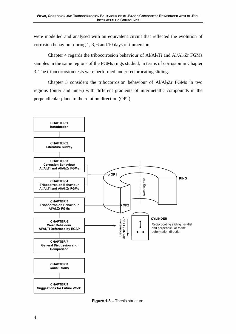
This dissertation is presented in nine chapters. In Figure 1.3, the structure of the
dissertation is presented and correlated with the materials considered in the work.
An introduction and a global presentation of the work of the thesis are provided
in Chapter 1.
In Chapter 2, a literature survey is presented, in which the relevant information
found in the literature related with the topics addressed in this dissertation is revised.
This includes aspects concerning the electrochemical characteristics and tribological
behaviour of the particulate aluminium matrix composites as well as some basic
concepts regarding the tribocorrosion phenomenon.
Chapter 3 describes the corrosion behaviour of Al/Al3Ti and Al/Al3Zr FGMs
processed by a centrifugal casting with centrifugal forces of 30, 60 and 120 G (units of
gravity). The studied region on the material was the outer region of the FGMs rings, in
the perpendicular plane to rotation axis (OP1) that was immersed in 0.6 M NaCl
solution (see Figure 1.3). Open circuit potential, potentiodynamic polarisation and
electrochemical impedance spectroscopy (EIS) tests were carried out. The EIS spectra
Figure 1.1 – Al-Ti phase diagram [16]. Figure 1.2 – Al-Zr phase diagram [16].
Al (l)+ Al3Ti (s)
Al (l)+ Al3Zr (s)
WEAR, CORROSION AND TRIBOCORROSION BEHAVIOUR OF AL-BASED COMPOSITES REINFORCED WITH AL-RICH INTERMETALLIC COMPOUNDS
4
Def
orm
atio
n di
rect
ion
EC
AP
were modelled and analysed with an equivalent circuit that reflected the evolution of
corrosion behaviour during 1, 3, 6 and 10 days of immersion.
Chapter 4 regards the tribocorrosion behaviour of Al/Al3Ti and Al/Al3Zr FGMs
samples in the same regions of the FGMs rings studied, in terms of corrosion in Chapter
3. The tribocorrosion tests were performed under reciprocating sliding.
Chapter 5 considers the tribocorrosion behaviour of Al/Al3Zr FGMs in two
regions (outer and inner) with different gradients of intermetallic compounds in the
perpendicular plane to the rotation direction (OP2).
Figure 1.3 – Thesis structure.
CHAPTER 9 Suggestions for Future Work
CHAPTER 8 Conclusions
CHAPTER 2 Literature Survey
CHAPTER 6 Wear Behaviour
Al/Al3Ti Deformed by ECAP
CHAPTER 5 Tribocorrosion Behaviour
Al/Al3Zr FGMs
CHAPTER 4 Tribocorrosion Behaviour Al/Al3Ti and Al/Al3Zr FGMs
CHAPTER 3 Corrosion Behaviour
Al/Al3Ti and Al/Al3Zr FGMs
CHAPTER 7 General Discussion and
Comparison
Rot
atin
g ax
is
OP2
OP1
Reciprocating sliding parallel and perpendicular to the deformation direction
RING CYLINDER
CHAPTER 1 Introduction
CHAPTER 1 Introduction
5
Chapter 6 explains the wear behaviour of an Al/Al3Ti composite plastically
deformed by ECAP from 1 up to 6 passes. Wear resistance experiments were carried out
in two directions, parallel and perpendicular to the deformation direction.
In Chapter 7, the experimental results obtained in Chapters 3 to 6 are compared
and discussed.
Chapter 8 summarizes the main conclusions of the present work.
Finally, Chapter 9 provides some suggestions for future research.
Table 1.1 – List of publications
Scientific Articles
S.C. Ferreira, L.A. Rocha, E. Ariza, P.D. Sequeira, Y. Watanabe, Corrosion Behaviour of Al/Al3Ti and Al/Al3Zr FGMs Produced by Centrifugal Casting, to be submitted for publication in Composites Science and Technology.
P.D. Sequeira, S.C. Ferreira, Y. Watanabe, L.A. Rocha, E. Ariza, J.R. Gomes, Microstructural Characterization and Tribocorrosion Behaviour of Al/Al3Ti and Al/Al3Zr FGMs, to be submitted for publication in Tribology International.
P.D. Sequeira, S.C. Ferreira, Y. Watanabe, L.A. Rocha, E. Ariza, J.R. Gomes, Microstructural Characterization and Wear Behaviour of Two-Phase Al-5 mass % Ti Alloy Deformed By Equal-Channel Angular Pressing, to be submitted for publication in Scripta Materialia.
Communications
S.C. Ferreira, L.A. Rocha, E. Ariza, J.R. Gomes, P.D. Sequeira, Y. Watanabe, Tribocorrosion Behaviour of Al/Al3Ti and Al/Al3Zr FGMs, Proceedings of the EUROCORR 2005 – European Corrosion Congress, Lisbon, Portugal, 4-8 September, 2005.
S.C. Ferreira, E. Ariza, L.A. Rocha, P.D. Sequeira, Y. Watanabe, Influence of the Reinforcing Particles Distribution on the Study of Tribocorrosion of Al/Al3Zr FGMs Produced by Centrifugal Casting, Proceedings of the LATINCORR 2006 – Congresso Latino-Americano de Corrosão, Fortaleza, Brasil, 21-26 Maio, 2006.
Chapters 3, 4 and 6 resulted in three scientific articles and Chapter 5 in a
communication (see Table 1.1). These research works were developed in two
institutions: Engineering Physics, Electronics and Mechanics Department, Graduate
School of Engineering, Nagoya Institute of Technology, Japan, in which was realized,
with the cooperation of P.D. Sequeira and Y. Watanabe, the processing of the Al/Al3Ti
and Al/Al3Zr FGMs by centrifugal casting and the Al-5 mass % Ti alloy deformed by
WEAR, CORROSION AND TRIBOCORROSION BEHAVIOUR OF AL-BASED COMPOSITES REINFORCED WITH AL-RICH INTERMETALLIC COMPOUNDS
6
ECAP; and the Research Centre on Interfaces and Surface Performance, Minho
University, Portugal, in which was realized, by myself, S.C. Ferreira, with collaboration
of L.A. Rocha, E. Ariza and J.R. Gomes, the study of corrosion and tribocorrosion
behaviour of Al/Al3Ti and Al/Al3Zr FGMs and the tribological behaviour of the Al-5
mass % Ti alloy deformed by ECAP.
1.1 – References
[1] D. B. Miracle, Comp. Sci. Tech. 65 (2005) 2526.
[2] R. Rodríguez-Castro, R.C. Wetherhold, M.H. Kelestemur, Mater. Sci. Eng.
A323 (2002) 445.
[3] R. Rodríguez-Castro, J. Mater. Sci. 37 (2002) 1813.
[4] A. Velhinho, P.D. Sequeira, R. Martins, G. Vignoles, F.B. Fernandes, J.D.
Botas, L.A. Rocha, Nuclear Instr. Methods Phys Res. B 200 (2003) 295.
[5] Y. Watanabe, N. Yamanaka, Y. Fukui, Z. Metallkd. 88 (1997) 717.
[6] Y. Watanabe, N. Yamanaka, Y. Fukui, Metall. Mater. Trans. A 30A (1999)
3253.
[7] Y. Watanabe, Y. Fukui, Rec. Res. Devel. Metall. Mater. Sci. 4 (2000) 51.
[8] Y. Watanabe, Y. Fukui, Aluminum Trans. 2 (2000) 195.
[9] Y. Watanabe, H. Eryu, K. Matsuura, Acta Mater. 49 (2001) 775.
[10] Y. Watanabe, A. Kawamoto, K. Matsuda, Compo. Sci. Tech. 62 (2002) 881.
[11] Y. Watanabe, Y. Fukui, in Current Issues on Multidisciplinary Microscopy
Research and Education, ed A. Méndez-Vilas and L. Labajos-Broncano, FORMATEX,
Badajoz, (2004) 189.
[12] P.D. Sequeira, Y. Watanabe, L.A. Rocha, Mater. Sci. Forum, 492 (2005) 609.
[13] P.D. Sequeira, Y. Watanabe, L.A. Rocha, Sol. Stat Phen. 105 (2005) 425.
[14] P.D. Sequeira, Ph.D. Thesis, Nagoya Institute Technology, Nagoya, 2006.
[15] Y. Watanabe, T. Nakamura, Intermetallics 9 (2001) 33.

CHAPTER 1 Introduction
7
[16] http://www.infomet.com.br/diagramas_fases.php.

CHAPTER 2 Literature Review
9
CHAPTER 2
Literature Review
In this chapter a brief literature survey, referring to the most important topics
related with this dissertation is presented. This includes subjects such as the properties
of intermetallic phases in aluminium alloys, the microstructural difference between
MMCs and FGMs, the effect of the processing parameters by centrifugal casting on the
gradient distribution of the dispersed particles in FGMs, the electrochemical
characteristics of intermetallic phases in aluminium matrix composites, a succinct
description of the EIS technique, the tribological behaviour of the particulate aluminium
matrix composites and finally some concepts related with the tribocorrosion
phenomenon. Some results obtained by other authors will be presented.
2.1 – Intermetallic Phases in Aluminium Alloys
Recently transition metal tri-aluminides have received increasing attention due
to their low densities, good oxidation resistance, high melting point and good thermal
stability. Such attractive characteristics make tri-aluminides Al3X (Ti, V, Zr, Nb, Hf,
Ta) potential candidates for high temperature structural materials. However, britleness
at low temperatures has limited the application of these materials [1-5].
According to the Al-Ti and Al-Zr phase diagrams (see Figure 1.1 and 1.2), the
intermetallics Al3Ti and Al3Zr are formed through peritectic reaction and congruent
melting, respectively. Both compounds have similar atomic structures, D022 in Al3Ti
and D023 in Al3Zr, with the same tetragonal (space group: I4/mmm) [3]. However, as it
was said previously, there are problems to be overcome for the practical use of Al3Ti
and Al3Zr as structural materials. The lack of ductility of tri-aluminides is attributed to
WEAR, CORROSION AND TRIBOCORROSION BEHAVIOUR OF AL-BASED COMPOSITES REINFORCED WITH AL-RICH INTERMETALLIC COMPOUNDS
10
their low crystal symmetry of the tetragonal D022 or D023 structures [1-5]. That is, they
do not have a sufficient number of equivalent slip systems to satisfy the von-Mises
criterion for slip deformation in polycrystals. In Al3X intermetallics, the tetragonal D022
or D023 structure is closely related to the cubic L12 structure (Pm3m) that has five
independent slip systems [1]. Structural isotropy is expected to improve the
deformability of the material because the isotropy increases the variants of active slip
systems for dislocation motions. Thus, the stabilization of the L12 structure is of great
interest for practical purposes as well as for the comprehensive understanding of
stabilization. A number of studies have recently been devoted to determine the effect of
the presence of third elements (Cr, Mn, Fe, Co, Ni, Cu, Zn, Ag and Pd) in the
stabilisation of the L12 structure [4]. Since the L12 structure has more slip systems, the
ductility of Al3Ti and Al3Zr is improved. However, neither the origin of this effect nor
the influences of atom-species/quantities is fully understood yet. One alternative
solution that improves this problem is to disperse intermetallic compound particles in a
ductile phase material [6,7]. A proper gradient distribution of intermetallic compounds
would result in better properties than a homogeneous distribution, based on the concept
of functionally graded materials (FGMs) [8-14].
2.2 – Al-Based FGMs Manufactured by Centrifugal Method
In last years, gradients at the microstructure level, composition and/or properties
in some specific directions are being introduced in advanced engineering components.
In particular, an extensive work has been made in the area of aluminium based alloys-
functionally graded materials produced by centrifugal casting and reinforced with
particles [15-26].
Figure 2.1 illustrates the functional and compositional differences between
conventional and FGM composites. Particle-dispersed composites shown in Figure 2.1
a) are regarded as macroscopically homogeneous and microscopically inhomogeneous
and thus the characteristics of the composite are assumed homogeneous on a
macroscopic scale. The properties of this material do not change significantly within the
samples. Figure 2.1 b) induces non-uniform distributions of reinforcement in composite,

CHAPTER 2 Literature Review
11
creating multiple functions within the material. That is, the composition and/or
microstructure vary gradually from one surface to the other. In the absence of a
macroscopic interface in FGMs, their properties should change continuously
[10,11,23,26].
Func
tions
of M
ater
ial 1 - Young's Modulus
2 - Thermal Conductivity
3 - Thermal Expancion Coefficient
Func
tions
of M
ater
ial 1
2
3
Material A Material B
a) Homogeneous Composites b) FGM
Figure 2.1 – The functional and compositional differences between conventional composites
and FGM. (Adapted from [11]).
In Al/intermetallic compound FGMs, the particles are used to provide
mechanical resistance, hardness, heat resistance, while, the aluminium matrix are used
to offer the ductility, thermal conductivity and mechanical strength.
An advanced composite in the form of a functionally graded material (FGM)
holds continuous changes of the microstructure, composition and/or properties in some
specific directions. The variation of properties can be adjusted by controlling the
microstructure and/or composition and is an important factor to describe the functions
of FGMs.
WEAR, CORROSION AND TRIBOCORROSION BEHAVIOUR OF AL-BASED COMPOSITES REINFORCED WITH AL-RICH INTERMETALLIC COMPOUNDS
12
One of the promising FGM fabrication methods is the centrifugal method. Fukui
and colleagues [8-17,19,20,25-27] have studied and optimized both the FGM
fabrication method, as well as possible systems of Al alloys that can form a FGM by
centrifugal method.
The centrifugal method is applicable to mass production of both small and large
FGMs components at a low cost. In this method, a centrifugal force is applied to a
homogeneous molten composite, dispersed with ceramic or intermetallic compounds
particles driving the formation of the desired gradation. Several parameters determine
the microstructure and the distribution of particles inside the casting. These parameters
are the size and initial concentration of particles, the centrifugal force, and the cooling
rate, which is controlled by: temperature of the mould, pouring temperature, cooling
delay, cooling of the mould, cooling of the casting, and heat transfer between the mould
and the melt [22].
The centrifugal casting is a pressure casting method in which the force of gravity,
when pouring molten metal into the mould, is increased by rotating or spinning the
mould assembly [8-27]. The main advantages of centrifugal casting are good mould
filling combined with good microstructural control, which usually give excellent
mechanical properties [10,11].
The centrifugal casting techniques have already been tested with aluminium
alloy melts containing ceramics particles, Al/SiC [21-23], Al/Shirasu [10,11,19],
Al/AlB2 [24] and intermetallic compounds Al/Al3Ti [8,9,12,13,26], Al/Al3Zr [13,26],
Al/Al3Ni [28], Al/(Al3Ti+Al3Ni) [29] andAl/Al2Cu [30] to obtain non-homogeneous
materials.
Al/intermetallic compounds FGMs fabricated by centrifugal casting have been
extensively studied because they overcome the interface problem found in artificial
composites such as Al/SiC or Al/Al2O3 for example, and have a lot of advantages such
as clean interfaces between reinforced phase and matrix, excellent properties, simple
fabrication technology, easiness to control technology parameters, small investment and
adaptability to large-scale industry production [31].

CHAPTER 2 Literature Review
13
2.3 – Al/Intermetallic Compound FGMs
The fabrication of the Al/intermetallic compounds FGMs by the centrifugal
method can be classified into two categories based on the relation between the
processing temperature and the liquidus temperature of master alloy [10,11,20,26-
28,30]. One is the centrifugal solid-particle method where the processing temperature is
lower than the liquidus temperature of the master alloy and the dispersed solid phase in
the master alloy remains in a liquid matrix. The mechanism to form a graded
composition is the same as the case of metal/ceramic FGMs by the centrifugal method.
The other is the centrifugal in-situ method where the processing temperature is higher
than the liquidus temperature of the master alloy. Al/Al3Ti and Al/Al3Zr FGM are
typical examples of systems fabricated by the centrifugal solid-particle method. The
liquidus temperature of Al-Ti and Al-Zr master alloys are higher than the processing
temperature. Al/Al3Ni and Al/Al2Cu FGMs are examples of the application of the
centrifugal in-situ method. The liquidus temperatures of both Al-Ni and Al-Cu master
alloys are lower than the processing temperature. It should be referred that a system
such as the Al/(Al3Ti+Al3Ni) is named a hybrid FGM because the fabrication is done at
the same time with the centrifugal solid-particle and in-situ methods [27,29]. It uses Al-
Ti and Al-Ni master alloys simultaneously and the processing temperature is lower than
the liquidus temperature of the Al-Ti master alloy but higher than that of the Al-Ni
master alloy.
In this work the processing method of the systems Al/Al3Ti and Al/Al3Zr FGMs,
will be described, where Al3Ti and Al3Zr have a higher melting point than the
processing temperature. The initial master alloys for the fabrication of the Al/Al3Ti and
Al/Al3Zr FGMs were commercial Al alloys with 5 mass % Ti and 5 mass % Zr, which
contains Al3Ti and Al3Zr in Al matrix, respectively. Since the melting temperature of
these intermetallics platelets are relatively high (i.e., 1615 K for Al3Ti [11], and 1860 K
for Al3Zr [31]), the alloys were heated to a temperature (1173 K) where the platelets
remained solid in the liquid Al matrix and a centrifugal force was applied during the
casting process. Three levels of centrifugal force were applied, which are characterized
by G numbers of 30, 60 and 120. Here, the G number is the ratio of the centrifugal force
to gravity and is given by the following equation [10,11,17,20,25]:
202 NDG = (2.1)

WEAR, CORROSION AND TRIBOCORROSION BEHAVIOUR OF AL-BASED COMPOSITES REINFORCED WITH AL-RICH INTERMETALLIC COMPOUNDS
14
where D0 is the diameter of the cast ring (m) and N is the velocity of the mould rotation
(s-1).
It is well known that the particle size distribution, as well as, the volume fraction
of particles in particle-reinforced, or dispersion-strengthened, composite material plays
an important role in controlling its properties [20]. Therefore, a detailed knowledge of
particle distributions is required to predict the corrosion, wear and tribocorrosion
behaviour of the FGMs.
It is also known that the motion of a particle in a viscous liquid under centrifugal
force is explained theoretically by the Stokes law [11,20,25]. Because the velocity of a
particle is proportional to the square of the particle diameter, the migration distance is
greater in the case of larger particles. In the FGMs fabricated by the centrifugal solid-
particle method, therefore, the particle size and the volume fraction are also expected to
be distributed along the radial direction. Results show that large particles migrate faster
than small particles i.e. the gradient of particle size arises [20]. The gradients,
depending on the characteristics of the particles, can be controlled by the difference of
migration rate among particles contained in the melt [17]. Consequently, the density of
the ring will increase toward the outer periphery of the ring when the densities of
particles are higher than that of the melt matrix [25]. Another important feature is that a
large number of platelets are arranged with their platelet planes nearly normal to the
radial direction, i.e., the centrifugal force direction. There is a tendency for the platelets
to align their platelet planes perpendicular to the centrifugal force direction. It was also
found that as the G number becomes larger, the orientation of the platelets becomes
stronger. The orientation of the platelets was from the angular velocity gradient of the
melt along the radial direction produced by the difference in the viscosity [10,11].
Since various processing parameters significantly influence the gradient
distribution of dispersed particles during FGM fabrication, it becomes difficult to
control the distribution of particles. The composition gradation was studied by computer
simulation by Watanabe et al. [11,17]. The process of the composition gradient
formation under a centrifugal force was simulated by considering the movement of each
spherical particle, which is suspended in the viscous liquid. The effect of processing
parameters on the gradient distribution of dispersed particles is show in Table 2.1.
CHAPTER 2 Literature Review
15
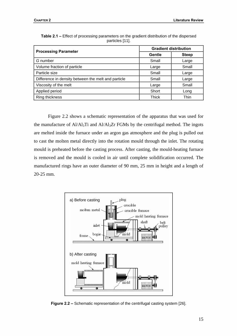
Table 2.1 – Effect of processing parameters on the gradient distribution of the dispersed particles [11].
Gradient distribution Processing Parameter
Gentle Steep G number Small Large Volume fraction of particle Large Small Particle size Small Large Difference in density between the melt and particle Small Large Viscosity of the melt Large Small Applied period Short Long Ring thickness Thick Thin
Figure 2.2 shows a schematic representation of the apparatus that was used for
the manufacture of Al/Al3Ti and Al/Al3Zr FGMs by the centrifugal method. The ingots
are melted inside the furnace under an argon gas atmosphere and the plug is pulled out
to cast the molten metal directly into the rotation mould through the inlet. The rotating
mould is preheated before the casting process. After casting, the mould-heating furnace
is removed and the mould is cooled in air until complete solidification occurred. The
manufactured rings have an outer diameter of 90 mm, 25 mm in height and a length of
20-25 mm.
Figure 2.2 – Schematic representation of the centrifugal casting system [26].
b) After casting
a) Before casting
WEAR, CORROSION AND TRIBOCORROSION BEHAVIOUR OF AL-BASED COMPOSITES REINFORCED WITH AL-RICH INTERMETALLIC COMPOUNDS
16
2.4 – Electrochemical Characteristics of Intermetallic Phases and Al-MMC
Research on the mechanical and corrosion properties of aluminium matrix
composites is still at the development stage, but the outlook is very promising. In recent
years the aerospace, military and automotive industries have been promoting the
technological development of composite materials to achieve good mechanical
strength/density and stiffness/density ratios [13,14,23,26,33].
One of the main obstacles to the use of composite materials is the influence of
the presence of the reinforcement on the corrosion resistance. This is particularly
important in Al alloy based composites, where a protective oxide film imparts corrosion
resistance. The addition of a reinforcing phase could lead to further discontinuities in
the film, increasing the number of sites where corrosion can be initiated and rendering
the composite liable to severe attack [33]. In the case of pure metals, pitting resistance is
dependant on the electrochemical stability of the passive film. However in the case of
Al alloy based composites, pitting is influenced by the distribution of particles.
Commonly such particles will exhibit electrochemical characteristics that differ from
the behaviour of the matrix, rendering the alloy susceptible to localized forms of
corrosion [33-36].
Pitting attack is reported to be the major form of corrosion in Al/SiC MMCs.
Studies on aluminium matrix composites have shown that a larger amount of pits are
formed on composites than on unreinforced alloys. Investigations to date have focused
on the effect of reinforcement and intermetallic cathodic phases on the pitting behaviour
[33-36]. Preferential attack occurs at the reinforcement/matrix interface. Furthermore,
pores, matrix second phases and interfacial reaction products can all influence corrosion
behaviour in a significant way [33].
In Al alloy based composites, the pit morphologies are circumferential and
appear as a ring of attack around a more or less intact particle or particle colony. The
attack appears to be mainly in the matrix phase. This type of morphology has been
ascribed to localized galvanic attack of the more active matrix by the nobler particle
[33-36].
CHAPTER 2 Literature Review
17
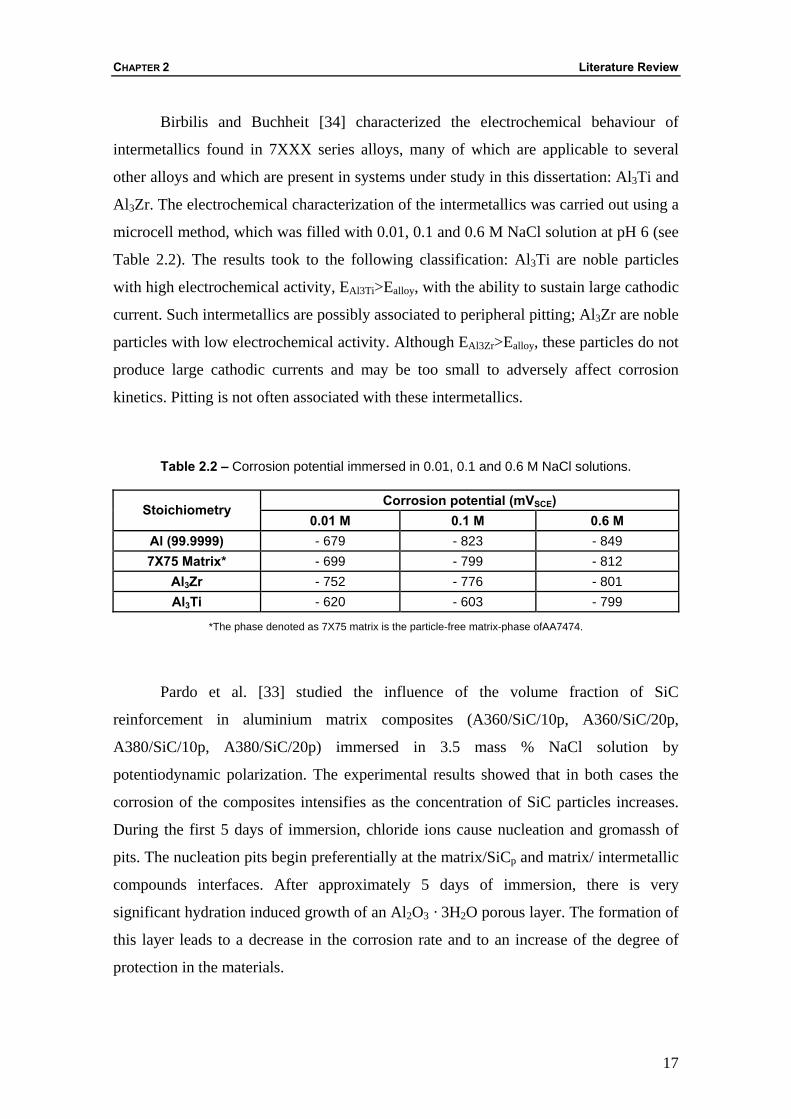
Birbilis and Buchheit [34] characterized the electrochemical behaviour of
intermetallics found in 7XXX series alloys, many of which are applicable to several
other alloys and which are present in systems under study in this dissertation: Al3Ti and
Al3Zr. The electrochemical characterization of the intermetallics was carried out using a
microcell method, which was filled with 0.01, 0.1 and 0.6 M NaCl solution at pH 6 (see
Table 2.2). The results took to the following classification: Al3Ti are noble particles
with high electrochemical activity, EAl3Ti>Ealloy, with the ability to sustain large cathodic
current. Such intermetallics are possibly associated to peripheral pitting; Al3Zr are noble
particles with low electrochemical activity. Although EAl3Zr>Ealloy, these particles do not
produce large cathodic currents and may be too small to adversely affect corrosion
kinetics. Pitting is not often associated with these intermetallics.
Table 2.2 – Corrosion potential immersed in 0.01, 0.1 and 0.6 M NaCl solutions.
Corrosion potential (mVSCE) Stoichiometry
0.01 M 0.1 M 0.6 M Al (99.9999) - 679 - 823 - 849 7X75 Matrix* - 699 - 799 - 812
Al3Zr - 752 - 776 - 801 Al3Ti - 620 - 603 - 799
*The phase denoted as 7X75 matrix is the particle-free matrix-phase ofAA7474.
Pardo et al. [33] studied the influence of the volume fraction of SiC
reinforcement in aluminium matrix composites (A360/SiC/10p, A360/SiC/20p,
A380/SiC/10p, A380/SiC/20p) immersed in 3.5 mass % NaCl solution by
potentiodynamic polarization. The experimental results showed that in both cases the
corrosion of the composites intensifies as the concentration of SiC particles increases.
During the first 5 days of immersion, chloride ions cause nucleation and gromassh of
pits. The nucleation pits begin preferentially at the matrix/SiCp and matrix/ intermetallic
compounds interfaces. After approximately 5 days of immersion, there is very
significant hydration induced growth of an Al2O3 · 3H2O porous layer. The formation of
this layer leads to a decrease in the corrosion rate and to an increase of the degree of
protection in the materials.
WEAR, CORROSION AND TRIBOCORROSION BEHAVIOUR OF AL-BASED COMPOSITES REINFORCED WITH AL-RICH INTERMETALLIC COMPOUNDS
18
The desirable mechanical properties of Al/Al3Ti and Al/Al3Zr FGMs are
developed as a result of heterogeneous microstructures of Al-Ti and Al-Zr commercial
aluminium alloys by the centrifugal method [26]. This work intends to study the effect
of the particle intermetallics, Al3Ti and Al3Zr on the corrosion resistance of Al/Al3Ti
and Al/Al3Zr FGMs, respectively, by electrochemical techniques.
2.5 – EIS Fundamentals and Equivalent Circuits
A perturbation sinusoidal voltage E = E0 sin (ωt) is applied at frequency ω to the
electrode system under test in electrochemical impedance spectroscopy (EIS)
measurement. The response is analysed in terms of the resultant current I = I sin(ωt +
α), where α represents a characteristic phase angle shift. The corresponding complex
impedance spectrum Z(ω), obtained by varying the signal frequency ω, is expressed in
terms of the displacement of the vector Z(ω). In the plane of Cartesian co-ordinates, an
impedance is expressed by its real (ZR) and imaginary (ZI) parts, i.e., Z(ω) =ZR + jZI.
The modulus |Z| and phase angle α of Z(ω) can be obtained from |Z| = 22IR ZZ + and α
= arctan(ZR / ZI), respectively. Over a frequency bandwidth of interest, the impedance
spectrum can be presented in various ways; typically in the well-known plot of Nyquist
(ZI as the Y-axis and ZR as the X-axis vs ω) or Bode plots (|Z| and α vs ω) [37-40].
The impedance spectrum reflects dialectic behaviour, oxidation-reduction
reactions and mass migration across the electrochemical interface, which is determined
by the electrical and chemical properties of the corrosive medium, and the electrode
materials. Modelling of EIS spectra, which forms an essential part of EIS studies, uses
an equivalent circuit to describe the electrochemical interface, such that the theoretical
impedance of a proposed circuit can be derived as a multivariable function. By adjusting
the variables one can achieve the fit of the theoretical spectrum to the experimental one
within the frequency domain. Then, the information regarding the electrochemical
corrosion can be extracted through the appropriate interpretation of the variables
[37,38,40]. Followed it is described two types of behaviours, non-active metals and
active metals.
The non-active metals may have high enough chemical stability in molten-salt
systems. This fact may mean that these metals do not have enough activation to react
CHAPTER 2 Literature Review
19
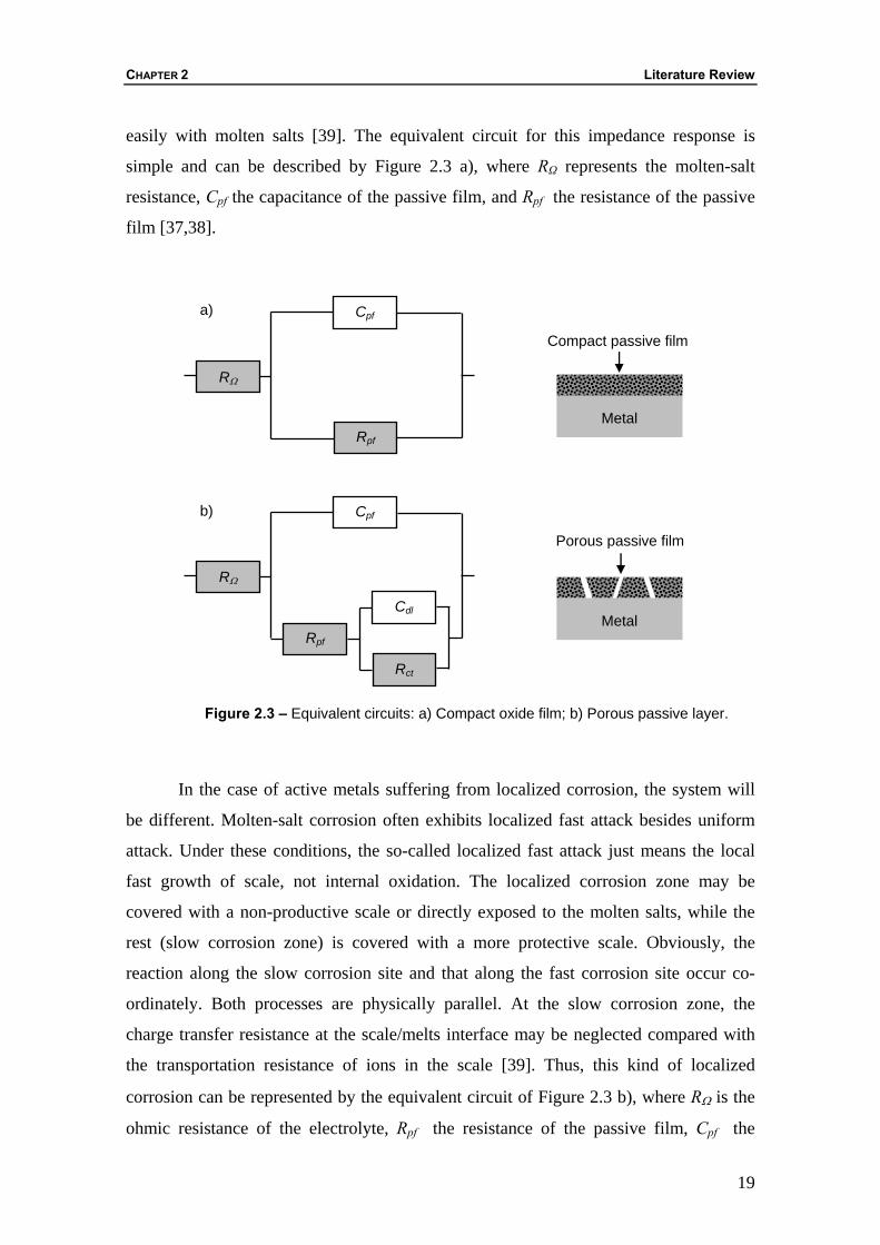
easily with molten salts [39]. The equivalent circuit for this impedance response is
simple and can be described by Figure 2.3 a), where RΩ represents the molten-salt
resistance, Cpf the capacitance of the passive film, and Rpf the resistance of the passive
film [37,38].
Figure 2.3 – Equivalent circuits: a) Compact oxide film; b) Porous passive layer.
In the case of active metals suffering from localized corrosion, the system will
be different. Molten-salt corrosion often exhibits localized fast attack besides uniform
attack. Under these conditions, the so-called localized fast attack just means the local
fast growth of scale, not internal oxidation. The localized corrosion zone may be
covered with a non-productive scale or directly exposed to the molten salts, while the
rest (slow corrosion zone) is covered with a more protective scale. Obviously, the
reaction along the slow corrosion site and that along the fast corrosion site occur co-
ordinately. Both processes are physically parallel. At the slow corrosion zone, the
charge transfer resistance at the scale/melts interface may be neglected compared with
the transportation resistance of ions in the scale [39]. Thus, this kind of localized
corrosion can be represented by the equivalent circuit of Figure 2.3 b), where RΩ is the
ohmic resistance of the electrolyte, Rpf the resistance of the passive film, Cpf the
Cpf
Rpf
RΩ
Metal
Compact passive film
Rct
Cpf
Rpf
RΩ
Cdl Metal
Porous passive film
a)
b)
WEAR, CORROSION AND TRIBOCORROSION BEHAVIOUR OF AL-BASED COMPOSITES REINFORCED WITH AL-RICH INTERMETALLIC COMPOUNDS
20
capacitance of the passive film, Cdl double-layer capacitance, Rct charge-transfer
resistance [37,38].
The theory of this powerful analysis technique is detailed in Refs. 37 and 38.
2.6 – Tribogical Behaviour of the Particulate Reinforced Al-Based MMCs
MMCs, in particular the aluminium Al-based MMCs, have been widely
researched for various applications, such aerospace and automotive components. This
wider interest is because of the fact that these composites have better higher strength,
hardness, strength to weight ratio, wear resistance and in some cases have higher
strength at relatively elevated temperatures over conventional monolithic base Al alloys
[41-45]. Ceramics fibres, whiskers, and particle reinforced aluminium alloys are now
considered as candidate tribomaterials [42,44]. The strength of discontinuously
reinforced MMCs is not as high as that of continuously reinforced composites, but the
properties and cost of discontinuous MMCs make them useful as wear-resistance
materials [41]. For example, Motorola’s Iridium satellites structural parts are made of
ceramic reinforced particle aluminium matrix composites (PMMC). Other examples
include ventral fins guide vanes in Pratt & Whitney 4000 series turbine engines, GM
Corvettes and pickups drive shafts, electric vehicle brake rotors, racing bicycle parts and
golf clubs [43]. Most of PMMCs use reinforcement that range in diameter from 3 to 80
µm [43]. PMMCs can be produced through a number of routes including melt
processing and powder metallurgy. Melt processing has some important advantages,
e.g. better matrix–particle bonding, easier control of matrix structure, simplicity and low
cost of processing compared with powder metallurgy [46].
There have been a large number of studies of the friction and wear properties of
these materials. However, discrepancies among the results have been reported. These
discrepancies may come from the large number of variables which can affect wear
mechanisms and wear rates. These include, as principal tribological parameters that
control the friction and wear performance of discontinuously reinforced aluminium
composites, two categories [47]: mechanical and physical factors (extrinsic to the
material undergoing surface interaction), e.g. the effect of normal load on the tribo-
CHAPTER 2 Literature Review
21
contact, the sliding velocity, the sliding distance (transient and steady state period), the
reinforcement orientation for non-equiaxed particulates, the environment and
temperature, the surface finish and the counterpart; and material factors (intrinsic to the
material undergoing surface interaction), e.g. the reinforcement type, the reinforcement
size and size distribution, the reinforcement shape, the matrix microstructure, and
finally the reinforcement volume fraction. As a result, a general statement can not be
made concerning the wear rate of a composite in relation to the matrix. In some cases,
the composite has a wear rate lower than that of the matrix alloy [41-46] and in others
the composite has a higher wear rate than the matrix alloy [48].
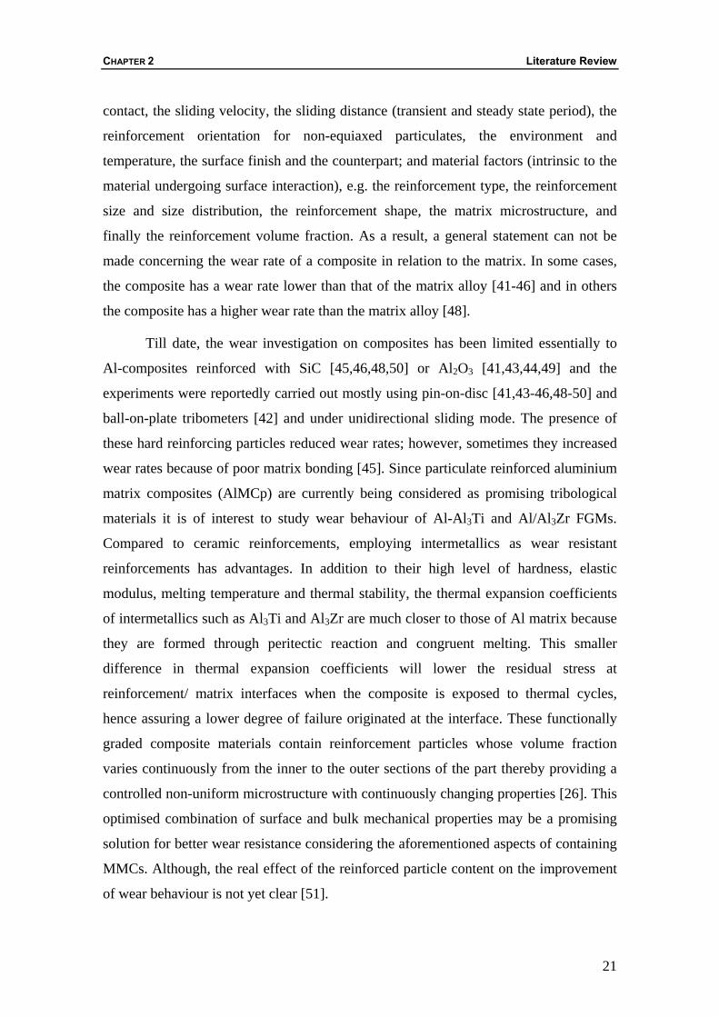
Till date, the wear investigation on composites has been limited essentially to
Al-composites reinforced with SiC [45,46,48,50] or Al2O3 [41,43,44,49] and the
experiments were reportedly carried out mostly using pin-on-disc [41,43-46,48-50] and
ball-on-plate tribometers [42] and under unidirectional sliding mode. The presence of
these hard reinforcing particles reduced wear rates; however, sometimes they increased
wear rates because of poor matrix bonding [45]. Since particulate reinforced aluminium
matrix composites (AlMCp) are currently being considered as promising tribological
materials it is of interest to study wear behaviour of Al-Al3Ti and Al/Al3Zr FGMs.
Compared to ceramic reinforcements, employing intermetallics as wear resistant
reinforcements has advantages. In addition to their high level of hardness, elastic
modulus, melting temperature and thermal stability, the thermal expansion coefficients
of intermetallics such as Al3Ti and Al3Zr are much closer to those of Al matrix because
they are formed through peritectic reaction and congruent melting. This smaller
difference in thermal expansion coefficients will lower the residual stress at
reinforcement/ matrix interfaces when the composite is exposed to thermal cycles,
hence assuring a lower degree of failure originated at the interface. These functionally
graded composite materials contain reinforcement particles whose volume fraction
varies continuously from the inner to the outer sections of the part thereby providing a
controlled non-uniform microstructure with continuously changing properties [26]. This
optimised combination of surface and bulk mechanical properties may be a promising
solution for better wear resistance considering the aforementioned aspects of containing
MMCs. Although, the real effect of the reinforced particle content on the improvement
of wear behaviour is not yet clear [51].
WEAR, CORROSION AND TRIBOCORROSION BEHAVIOUR OF AL-BASED COMPOSITES REINFORCED WITH AL-RICH INTERMETALLIC COMPOUNDS
22
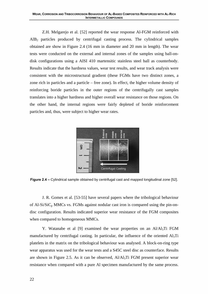
Z.H. Melgarejo et al. [52] reported the wear response Al-FGM reinforced with
AlB2 particles produced by centrifugal casting process. The cylindrical samples
obtained are show in Figure 2.4 (16 mm in diameter and 20 mm in length). The wear
tests were conducted on the external and internal zones of the samples using ball-on-
disk configurations using a AISI 410 martensitic stainless steel ball as counterbody.
Results indicate that the hardness values, wear test results, and wear track analysis were
consistent with the microstructural gradient (these FGMs have two distinct zones, a
zone rich in particles and a particle – free zone). In effect, the higher volume density of
reinforcing boride particles in the outer regions of the centrifugally cast samples
translates into a higher hardness and higher overall wear resistance on those regions. On
the other hand, the internal regions were fairly depleted of boride reinforcement
particles and, thus, were subject to higher wear rates.
Figure 2.4 – Cylindrical sample obtained by centrifugal cast and mapped longitudinal zone [52].
J. R. Gomes et al. [53-55] have several papers where the tribological behaviour
of Al-Si/SiCp MMCs vs. FGMs against nodular cast iron is compared using the pin-on-
disc configuration. Results indicated superior wear resistance of the FGM composites
when compared to homogeneous MMCs.
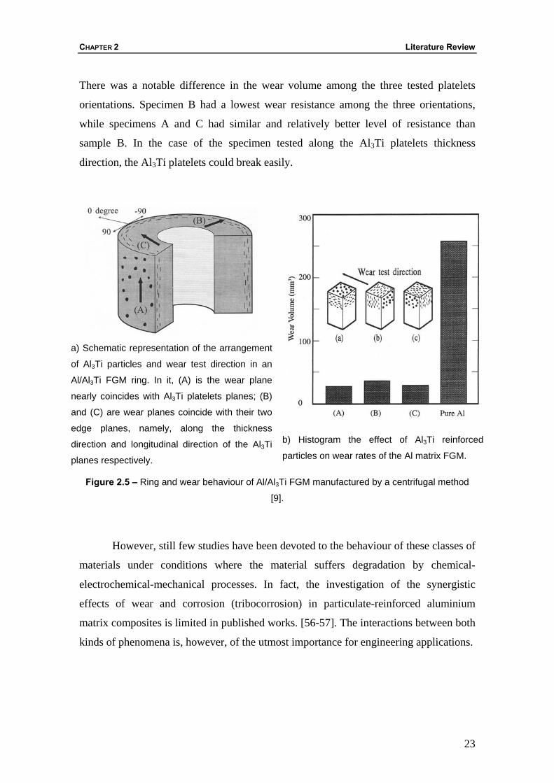
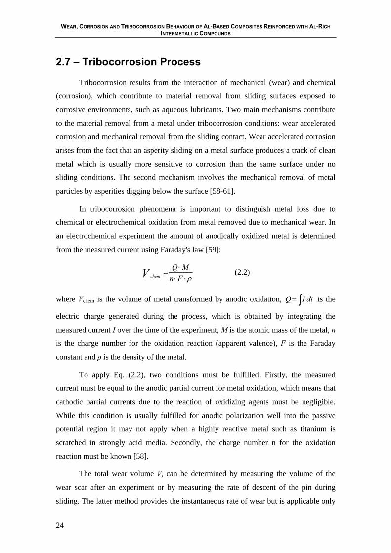
Y. Watanabe et al [9] examined the wear properties on an Al/Al3Ti FGM
manufactured by centrifugal casting. In particular, the influence of the oriented Al3Ti
platelets in the matrix on the tribological behaviour was analysed. A block-on-ring type
wear apparatus was used for the wear tests and a S45C steel disc as counterface. Results
are shown in Figure 2.5. As it can be observed, Al/Al3Ti FGM present superior wear
resistance when compared with a pure Al specimen manufactured by the same process.
CHAPTER 2 Literature Review
23
There was a notable difference in the wear volume among the three tested platelets
orientations. Specimen B had a lowest wear resistance among the three orientations,
while specimens A and C had similar and relatively better level of resistance than
sample B. In the case of the specimen tested along the Al3Ti platelets thickness
direction, the Al3Ti platelets could break easily.
a) Schematic representation of the arrangement
of Al3Ti particles and wear test direction in an
Al/Al3Ti FGM ring. In it, (A) is the wear plane
nearly coincides with Al3Ti platelets planes; (B)
and (C) are wear planes coincide with their two
edge planes, namely, along the thickness
direction and longitudinal direction of the Al3Ti
planes respectively.
b) Histogram the effect of Al3Ti reinforced
particles on wear rates of the Al matrix FGM.
Figure 2.5 – Ring and wear behaviour of Al/Al3Ti FGM manufactured by a centrifugal method
[9].
However, still few studies have been devoted to the behaviour of these classes of
materials under conditions where the material suffers degradation by chemical-
electrochemical-mechanical processes. In fact, the investigation of the synergistic
effects of wear and corrosion (tribocorrosion) in particulate-reinforced aluminium
matrix composites is limited in published works. [56-57]. The interactions between both
kinds of phenomena is, however, of the utmost importance for engineering applications.
WEAR, CORROSION AND TRIBOCORROSION BEHAVIOUR OF AL-BASED COMPOSITES REINFORCED WITH AL-RICH INTERMETALLIC COMPOUNDS
24
2.7 – Tribocorrosion Process
Tribocorrosion results from the interaction of mechanical (wear) and chemical
(corrosion), which contribute to material removal from sliding surfaces exposed to
corrosive environments, such as aqueous lubricants. Two main mechanisms contribute
to the material removal from a metal under tribocorrosion conditions: wear accelerated
corrosion and mechanical removal from the sliding contact. Wear accelerated corrosion
arises from the fact that an asperity sliding on a metal surface produces a track of clean
metal which is usually more sensitive to corrosion than the same surface under no
sliding conditions. The second mechanism involves the mechanical removal of metal
particles by asperities digging below the surface [58-61].
In tribocorrosion phenomena is important to distinguish metal loss due to
chemical or electrochemical oxidation from metal removed due to mechanical wear. In
an electrochemical experiment the amount of anodically oxidized metal is determined
from the measured current using Faraday's law [59]:
ρ⋅⋅⋅
=Fn
MQV chem (2.2)
where Vchem is the volume of metal transformed by anodic oxidation, ∫= dtIQ is the
electric charge generated during the process, which is obtained by integrating the
measured current I over the time of the experiment, M is the atomic mass of the metal, n
is the charge number for the oxidation reaction (apparent valence), F is the Faraday
constant and ρ is the density of the metal.
To apply Eq. (2.2), two conditions must be fulfilled. Firstly, the measured
current must be equal to the anodic partial current for metal oxidation, which means that
cathodic partial currents due to the reaction of oxidizing agents must be negligible.
While this condition is usually fulfilled for anodic polarization well into the passive
potential region it may not apply when a highly reactive metal such as titanium is
scratched in strongly acid media. Secondly, the charge number n for the oxidation
reaction must be known [58].
The total wear volume Vt can be determined by measuring the volume of the
wear scar after an experiment or by measuring the rate of descent of the pin during
sliding. The latter method provides the instantaneous rate of wear but is applicable only
CHAPTER 2 Literature Review
25
if no significant amounts of solid reaction products such as third body particles
accumulate in the contact during the experiment. From the total wear volume Vt and the
chemical wear volume Vchem determined from the electric charge, the mechanical wear
volume, Vmech, which is the volume of metal removed mechanically is obtained by
subtraction [59]:
VVV chemtmech−= (2.3)
It should be mentioned that this equation is valid independent of whether anodic
oxidation leads to formation of dissolved metal ions or of solid reaction products such
as oxide films. Unfortunately, there is no simple way to determine Vmech directly.
The tribocorrosion behaviour of sliding contacts under electrochemical control
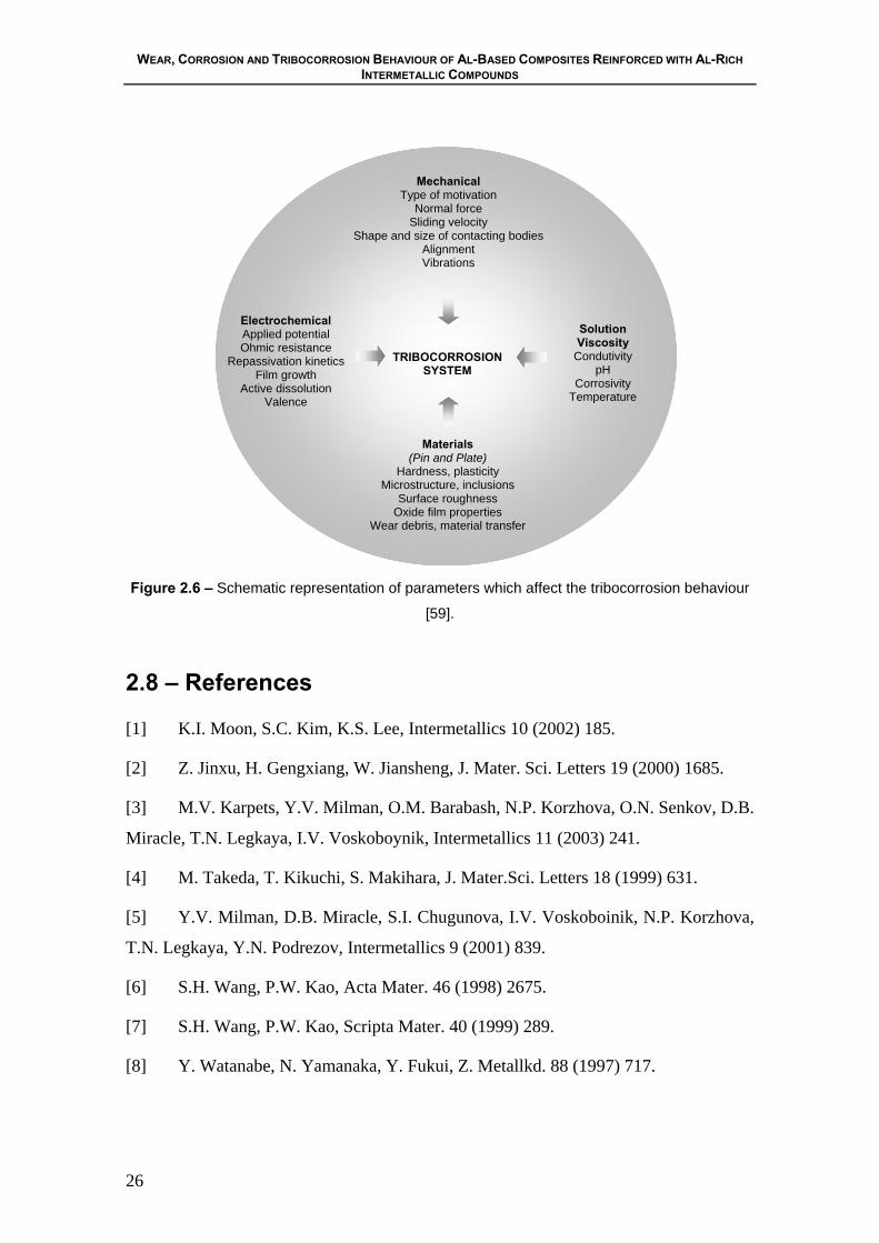
depends on many factors (Figure 2.6). Thus, the performance of electrochemically
controlled tribocorrosion systems is conditioned by four types of parameters, namely
[58-61]:
1) The mechanical solicitations which are related to equipment design and
operation;
2) The electrochemical conditions prevailing at the rubbing metal surfaces;
3) The solution properties at the contact region;
4) The materials involved in the contact and the surface properties of the sample
and the antagonist.
These parameters usually do not act independently, but their effects on the
tribocorrosion behaviour are mutually dependent.
WEAR, CORROSION AND TRIBOCORROSION BEHAVIOUR OF AL-BASED COMPOSITES REINFORCED WITH AL-RICH INTERMETALLIC COMPOUNDS
26
Figure 2.6 – Schematic representation of parameters which affect the tribocorrosion behaviour
[59].
2.8 – References
[1] K.I. Moon, S.C. Kim, K.S. Lee, Intermetallics 10 (2002) 185.
[2] Z. Jinxu, H. Gengxiang, W. Jiansheng, J. Mater. Sci. Letters 19 (2000) 1685.
[3] M.V. Karpets, Y.V. Milman, O.M. Barabash, N.P. Korzhova, O.N. Senkov, D.B.
Miracle, T.N. Legkaya, I.V. Voskoboynik, Intermetallics 11 (2003) 241.
[4] M. Takeda, T. Kikuchi, S. Makihara, J. Mater.Sci. Letters 18 (1999) 631.
[5] Y.V. Milman, D.B. Miracle, S.I. Chugunova, I.V. Voskoboinik, N.P. Korzhova,
T.N. Legkaya, Y.N. Podrezov, Intermetallics 9 (2001) 839.
[6] S.H. Wang, P.W. Kao, Acta Mater. 46 (1998) 2675.
[7] S.H. Wang, P.W. Kao, Scripta Mater. 40 (1999) 289.
[8] Y. Watanabe, N. Yamanaka, Y. Fukui, Z. Metallkd. 88 (1997) 717.
Materials (Pin and Plate)
Hardness, plasticity Microstructure, inclusions
Surface roughness Oxide film properties
Wear debris, material transfer
Mechanical Type of motivation
Normal force Sliding velocity
Shape and size of contacting bodies Alignment Vibrations
Solution Viscosity
Condutivity pH
Corrosivity Temperature
TRIBOCORROSION SYSTEM
Electrochemical Applied potential Ohmic resistance
Repassivation kinetics Film growth
Active dissolution Valence
CHAPTER 2 Literature Review
27
[9] Y. Watanabe, N. Yamanaka, Y. Fukui, Metall. Mater. Trans. A 30A (1999)
3253.
[10] Y. Watanabe, Y. Fukui, Rec. Res. Devel. Metall. Mater. Sci. 4 (2000) 51.
[11] Y. Watanabe, Y. Fukui, Aluminum Trans. 2 (2000) 195.
[12] Y. Watanabe, H. Eryu, K. Matsuura, Acta Mater. 49 (2001) 775.
[13] P.D. Sequeira, Y. Watanabe, L.A. Rocha, Mater. Sci. Forum, 492 (2005) 609.
[14] P.D. Sequeira, Y. Watanabe, L.A. Rocha, Sol. Stat Phen. 105 (2005) 425.
[15] Y. Fukui, JSME Int. J. Series III 34 (1991) 144.
[16] Y. Fukui, H. Kinoshita, K. Nakanishi, JSME Int. J. Series I 35 (1992) 95.
[17] Y. Watanabe, N. Yamanaka, Y. Fukui, Composites Part A 29A (1998) 595.
[18] J.W. Gao, C.Y. Wang, Mater. Sci. Eng. A292 (2000) 207.
[19] Y. Watanabe, N. Yamanaka, Y. Oya-Seimiya, Y. Fukui, Z. Metallkd. 92 (2001)
53.
[20] Y. Watanabe, A. Kawamoto, K. Matsuda, Compo. Sci. Tech. 62 (2002) 881.
[21] R. Rodríguez-Castro, R.C. Wetherhold, M.H. Kelestemur, Mater. Sci.Eng. A323
(2002) 445.
[22] R. Rodríguez-Castro, J. Mater. Sci. 37 (2002) 1813.
[23] A.J.C. Velhinho, Ph.D. Tesis, Universidade Nova de Lisboa, Lisboa, 2003.
[24] N.B. Duque, Z.H. Melgarejo, O. M. Suárez, Mater. Characterization 55 (2005)
167.
[25] T. Ogawa, Y. Watanabe, H. Sato, I.-S. Kim, Y. Fukui, Composites Part A (2005)
in press.
[26] P.D. Sequeira, Ph.D. Tesis, Nagoya Institute Technology, Nagoya, 2006.
[27] Y. Watanabe, Y. Fukui, in Current Issues on Multidisciplinary Microscopy
Research and Education, ed A. Méndez-Vilas and L.Labajos-Broncano, FORMATEX,
Badajoz, (2004) 189.

WEAR, CORROSION AND TRIBOCORROSION BEHAVIOUR OF AL-BASED COMPOSITES REINFORCED WITH AL-RICH INTERMETALLIC COMPOUNDS
28
[28] Y. Watanabe, R. Sato, K. Matsuda, Y. Fukui, Sci. Eng. Compos. Mater. 11
(2004) 185.
[29] Y. Watanabe, Y. Fukui, Intermetallics 9 (2001) 33.
[30] Y. Watanabe, S. Oike, Acta Mater. 53(200)1631.
[31] Q. Wang, Y. Wei, W. Chen, Y. Zhu, C. Ma, W. Ding, Mater. Letters 57 (2003)
3851.
[32] W. Miao, K. Tao, B. Li, B.X. Liu, J. Phys. D: Appl. Phys. 33 (2000) 2300.
[33] A. Pardo, M.C. Merino, S. Merino, F. Viejo, M. Carboneras, R. Arrabal, Corros.
Sci. 47 (2005) 1750.
[34] N. Birbilis, R. G. Buchheit, J. Electrochem. Soc. 152 (2005) B140.
[35] A. Aballe, M. Bethencourt, F.J. Botana, M.J. Cano, M. Marcos, Corros. Sci. 45
(2003) 161.
[36] A. Barbucci, G. Bruzzone, M. Delucchi, M. Panizza, G. Cerisola, Intermetallics
8 (2000) 305.
[37] R.G. Kelly, J.R. Scully, D.W. Shoesmith, R.G. Buchheit, Electrochemical
Techniques in Corrosion Science and Engineering, Marcel Dekker Inc., New York
(2003).
[38] W.S. Tait, An Introduction to Electrochemical Corrosion Testing for Practicing
Engineers and Scientists. PairODocs Publications, Racine, WI (1994).
[39] C.L. Zeng, W. Wang, W.T. Wu, Corros. Sci. 43 (2001) 787.
[40] C. Liu, Q. Bi, A. Leyland, A. Matthews, Corros. Sci. 45 (2003) 1243.
[41] O. Yilmaz, S. Buytoz, Compos. Sci. Technol. 61 (2001) 2381.
[42] D. Roy, B. Basu, A.B. Mallick, Intermetallics 13 (2005) 733.
[43] A.M. Al-Qutub, I.M. Allam, T.W. Qureshi, J. Mater. Process. Technol. 172
(2006) 327.
[44] M. Kök, Composites: Parte A 37 (2006) 457.
[45] M. Muratoglu, M. Aksoy, J. Mater. Process. Technol. (2006) in press.
[46] Y. Sahin, Mater. Des. (2006) in press.
CHAPTER 2 Literature Review
29
[47] A.P. Sannino, H.J. Rack, Wear 189 (1995) 1.
[48] R. Dasgupta, J. Compos. Mater.39 (2005) 1561.
[49] H. Sevik, S.C. Kurnaz, Mater. Des. 27 (2006) 676.
[50] P.N. Bindumadhavan, T.K. Chia, M. Chandrasekaran, H. K.Wah, L. N. Lam, O.
Prabhakar, Mater. Sci. Eng. A315 (2001) 217.
[51] J.R. Gomes, A. Ramalho, M.C. Gaspar, S.F. Carvalho, Wear 259 (2005) 545.
[52] Z.H. Melgarejo, O. M. Suárez, K. Sridharan, Scripta Mater (2006) in press.
[53] J.R. Gomes, A.S. Miranda, D.F. Soares, A.E. Dias, L.A. Rocha, S.J. Crnkovic,
R.F. Silva, Ceramics Trans. 114 (2000) 579.
[54] J.R. Gomes, A.S. Miranda, L.A. Rocha, S.J. Crnkovic, V. Silva, R.F. Silva, Int.
J. Appl. Mech. Eng. 7 (2002) 791.
[55] J.R. Gomes, L.A. Rocha, S.J. Crnkovic, R.F. Silva, A.S. Miranda, Mater. Sci.
Forum 423 (2003) 91.
[56] A. Velhinho, J.D. Botas, E. Ariza, J.R. Gomes, L.A. Rocha, Mater. Sci. Forum
455-456 (2004) 871.
[57] C.-K. Fang, C.C. Huang, T.H. Chuang: Met. Mater. Trans. A 30A (1999) 643.
[58] G. Zambelli, L. Vincent, Matériaux et Contact, Une Approche Tribologique,
Press Polytechniques et Universitaires Romandes, Lausanne, (1998).
[59] D. Landolt, S. Mischler, M. Stemp, Electrochim. Acta 46 (2001) 3913.
[60] P. Jemmely, S. Mischler, D. Landolt, Wear 237 (2000) 63.
[61] P. Ponthiaux, F. Wenger, D. Drees, J.P. Celis, Wear 256 (2004) 459

CHAPTER 3 Corrosion Behaviour of Al/Al3Ti and Al/Al3Zr FGMs Produced by Centrifugal Casting
31
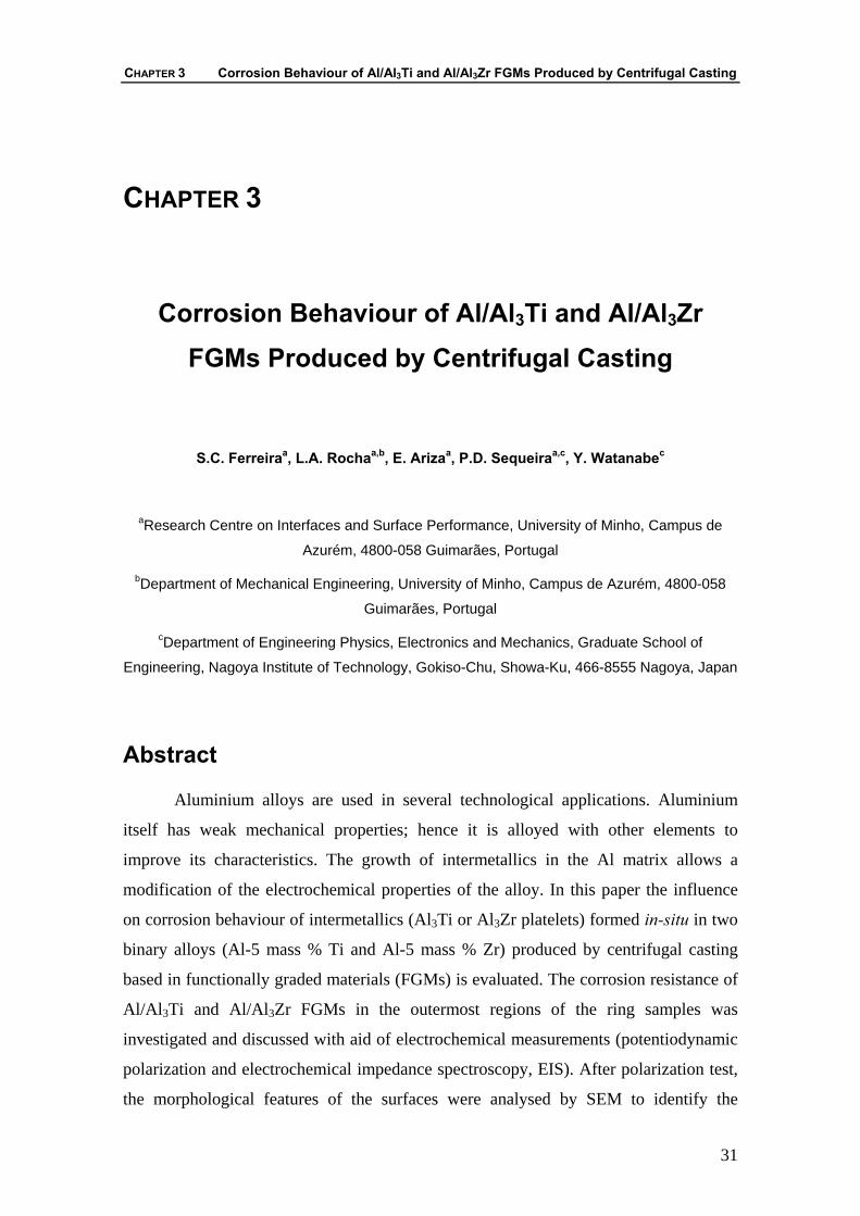
CHAPTER 3
Corrosion Behaviour of Al/Al3Ti and Al/Al3Zr FGMs Produced by Centrifugal Casting
S.C. Ferreiraa, L.A. Rochaa,b, E. Arizaa, P.D. Sequeiraa,c, Y. Watanabec
aResearch Centre on Interfaces and Surface Performance, University of Minho, Campus de
Azurém, 4800-058 Guimarães, Portugal
bDepartment of Mechanical Engineering, University of Minho, Campus de Azurém, 4800-058
Guimarães, Portugal
cDepartment of Engineering Physics, Electronics and Mechanics, Graduate School of
Engineering, Nagoya Institute of Technology, Gokiso-Chu, Showa-Ku, 466-8555 Nagoya, Japan
Abstract
Aluminium alloys are used in several technological applications. Aluminium
itself has weak mechanical properties; hence it is alloyed with other elements to
improve its characteristics. The growth of intermetallics in the Al matrix allows a
modification of the electrochemical properties of the alloy. In this paper the influence
on corrosion behaviour of intermetallics (Al3Ti or Al3Zr platelets) formed in-situ in two
binary alloys (Al-5 mass % Ti and Al-5 mass % Zr) produced by centrifugal casting
based in functionally graded materials (FGMs) is evaluated. The corrosion resistance of
Al/Al3Ti and Al/Al3Zr FGMs in the outermost regions of the ring samples was
investigated and discussed with aid of electrochemical measurements (potentiodynamic
polarization and electrochemical impedance spectroscopy, EIS). After polarization test,
the morphological features of the surfaces were analysed by SEM to identify the
WEAR, CORROSION AND TRIBOCORROSION BEHAVIOUR OF AL-BASED COMPOSITES REINFORCED WITH AL-RICH INTERMETALLIC COMPOUNDS
32
prevailing corrosion mechanisms on the surfaces. EIS measurements were performed at
increased immersion times (1, 3, 6 and 10 days). All tests were performed at ambient
temperature in a 0.6 M NaCl solution.
Keywords: Corrosion, Electrochemical Impedance Spectroscopy (EIS),
Al/Intermetallics Compounds, Functionaly Graded Materials (FGMs)
3.1 – Introduction
The corrosion behaviour of aluminium alloys has been the subject of a large
number of publications, since the naturally formed oxide film can give excellent
protection against corrosion, in addition to the advantages resulting from aluminium’s
low density [1]. Many commercial aluminium alloys are developed with a wide range of
mechanical properties stimulated by careful alloying additions and heat-treatments [2].
According to the Al-Ti and Al-Zr phase diagrams, the intermetallics Al3Ti and Al3Zr are
formed through peritectic reaction and congruent melting, respectively [3]. Both
compounds have similar atomic structures i.e. D022 in Al3Ti and D023 in Al3Zr with the
same tetragonal space group of I4/mmm and show high melting temperature, low
density, good oxidation resistance and good thermal stability [4].
The corrosion resistance of the aluminium alloys is usually dependent on the
metal heterogeneities and/or to the medium or exposure conditions. Heterogeneities in
the microstructure can cause formation of cathodic and anodic zones that promote
different forms of localized corrosion [5]. The production of local galvanic cells
promotes the dissolution of the less noble areas [6]. In the case of the aluminium alloys,
the heterogeneities are frequently intermetallic compounds distributed throughout the
metallic matrix that can be either anodic or cathodic relatively to the matrix. In the case
of the Al3Ti and Al3Zr intermetallic compounds, they show a more cathodic potential in
comparison with the pure Al. Consequently, depending on the experimental parameters,
they are able of provoking localized corrosion in the metallic matrix surrounding the
precipitates (Al[99,9999] = -849 mVSCE ; Al3Ti = -799 mVSCE and Al3Zr = -801 mVSCE in
0.6 M NaCl solution) [2]. Additionally, the presence of intermetallics in the aluminium
CHAPTER 3 Corrosion Behaviour of Al/Al3Ti and Al/Al3Zr FGMs Produced by Centrifugal Casting
33
matrix can difficult the growth or promote failures of the protective oxide layer formed
in air or in aqueous solutions on alloys that are likely to be passivated [2,5].
Functionally graded metal matrix composites (FGMMCs) are considered as
engineered materials systems to achieve optimum performance in the intended
application. FGMMCs are produced using techniques that introduce spatial differential
distribution of the reinforcing along the component. As end result a gradient of
mechanical properties from the surface up to the bulk of the components is obtained.
The fabrication of the Al/intermetallic compounds FGMs by the centrifugal method is
similar to the fabrication of Al/ceramic FGMs [7-16]. This method, proposed by Fukui
et al. [7], is named solid-particle method and is based on the application of a centrifugal
force to homogeneous molten composites, dispersed with ceramics or intermetallic
particles, leading to the formation of the desired gradation. The composition gradient is
then achieved primarily by the difference in the centrifugal force produced by the
difference in density between the molten metal and particles. The processing conditions
by centrifugal solid-particle as well as the mechanical properties of Al/intermetallic
compound FGMs, namely of the Al/Al3Ti and Al/Al3Zr systems, have been investigated
[15].
In this paper, corrosion behaviour of the Al/Al3Ti and Al/Al3Zr FGMs in a 0.6
M NaCl has been studied in the outer region of the FGMs rings manufactured by
centrifugal casting. For such, open-circuit potential, potentiodynamic polarisation and
electrochemical impedance spectroscopy (EIS) tests were carried out. The EIS spectra
were modelled and analysed with an equivalent circuit that reflected the evolution of
corrosion behaviour during 1, 3, 6 and 10 days of immersion.
3.2 – Experimental Methods
The Al/Al3Ti and Al/Al3Zr FGMs were produced by the centrifugal method,
from Al-5 mass % Ti and Al-5 mass % Zr commercial alloys, respectively, as described
by Sequeira et al. [15]. Since the relative atomic masses of Al, Ti and Zr are 26.98,
47.88 and 91.22, respectively, the theoretical volume fraction of Al3Ti in the master
alloy was calculated to be approximately 11 vol % and that of Al3Zr as approximately 7
vol %.
WEAR, CORROSION AND TRIBOCORROSION BEHAVIOUR OF AL-BASED COMPOSITES REINFORCED WITH AL-RICH INTERMETALLIC COMPOUNDS
34
Rotating axis
Studied outer region 5 mm of the periphery
Sample
In the centrifugal method the alloy is heated up to a temperature located between
its solidus and liquidus temperatures, were most of the intermetallic platelets remain
solid in a liquid Al-based matrix. It is then poured into a rotating mould in order to
obtain ring-shaped samples which have an outer diameter of 90 mm, 25 mm in height
and a length of 20-25 mm. The temperature of the melting furnace was 1173 K and the
applied centrifugal casting forces were 30, 60 and 120 G (units of gravity).
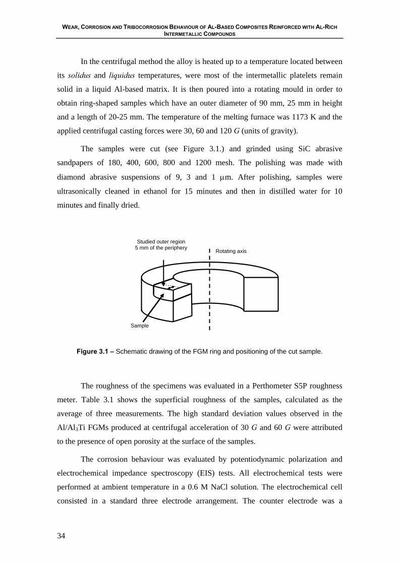
The samples were cut (see Figure 3.1.) and grinded using SiC abrasive
sandpapers of 180, 400, 600, 800 and 1200 mesh. The polishing was made with
diamond abrasive suspensions of 9, 3 and 1 μm. After polishing, samples were
ultrasonically cleaned in ethanol for 15 minutes and then in distilled water for 10
minutes and finally dried.
Figure 3.1 – Schematic drawing of the FGM ring and positioning of the cut sample.
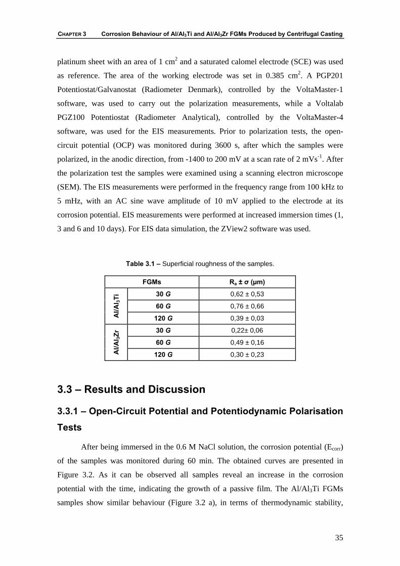
The roughness of the specimens was evaluated in a Perthometer S5P roughness
meter. Table 3.1 shows the superficial roughness of the samples, calculated as the
average of three measurements. The high standard deviation values observed in the
Al/Al3Ti FGMs produced at centrifugal acceleration of 30 G and 60 G were attributed
to the presence of open porosity at the surface of the samples.
The corrosion behaviour was evaluated by potentiodynamic polarization and
electrochemical impedance spectroscopy (EIS) tests. All electrochemical tests were
performed at ambient temperature in a 0.6 M NaCl solution. The electrochemical cell
consisted in a standard three electrode arrangement. The counter electrode was a
CHAPTER 3 Corrosion Behaviour of Al/Al3Ti and Al/Al3Zr FGMs Produced by Centrifugal Casting
35
platinum sheet with an area of 1 cm2 and a saturated calomel electrode (SCE) was used
as reference. The area of the working electrode was set in 0.385 cm2. A PGP201
Potentiostat/Galvanostat (Radiometer Denmark), controlled by the VoltaMaster-1
software, was used to carry out the polarization measurements, while a Voltalab
PGZ100 Potentiostat (Radiometer Analytical), controlled by the VoltaMaster-4
software, was used for the EIS measurements. Prior to polarization tests, the open-
circuit potential (OCP) was monitored during 3600 s, after which the samples were
polarized, in the anodic direction, from -1400 to 200 mV at a scan rate of 2 mVs-1. After
the polarization test the samples were examined using a scanning electron microscope
(SEM). The EIS measurements were performed in the frequency range from 100 kHz to
5 mHz, with an AC sine wave amplitude of 10 mV applied to the electrode at its
corrosion potential. EIS measurements were performed at increased immersion times (1,
3 and 6 and 10 days). For EIS data simulation, the ZView2 software was used.
Table 3.1 – Superficial roughness of the samples.
FGMs Ra ± σ (µm)
30 G 0,62 ± 0,53
60 G 0,76 ± 0,66
Al/A
l 3Ti
120 G 0,39 ± 0,03
30 G 0,22± 0,06
60 G 0,49 ± 0,16
Al/A
l 3Zr
120 G 0,30 ± 0,23
3.3 – Results and Discussion
3.3.1 – Open-Circuit Potential and Potentiodynamic Polarisation Tests
After being immersed in the 0.6 M NaCl solution, the corrosion potential (Ecorr)
of the samples was monitored during 60 min. The obtained curves are presented in
Figure 3.2. As it can be observed all samples reveal an increase in the corrosion
potential with the time, indicating the growth of a passive film. The Al/Al3Ti FGMs
samples show similar behaviour (Figure 3.2 a), in terms of thermodynamic stability,
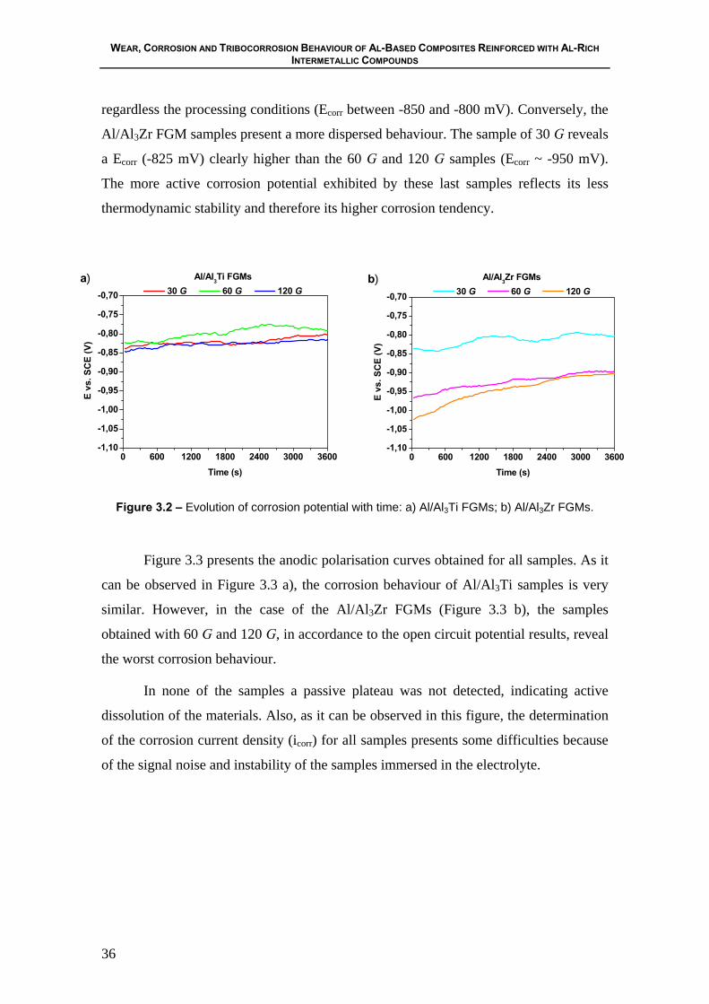
WEAR, CORROSION AND TRIBOCORROSION BEHAVIOUR OF AL-BASED COMPOSITES REINFORCED WITH AL-RICH INTERMETALLIC COMPOUNDS
36
regardless the processing conditions (Ecorr between -850 and -800 mV). Conversely, the
Al/Al3Zr FGM samples present a more dispersed behaviour. The sample of 30 G reveals
a Ecorr (-825 mV) clearly higher than the 60 G and 120 G samples (Ecorr ~ -950 mV).
The more active corrosion potential exhibited by these last samples reflects its less
thermodynamic stability and therefore its higher corrosion tendency.
0 600 1200 1800 2400 3000 3600-1,10
-1,05
-1,00
-0,95
-0,90
-0,85
-0,80
-0,75
-0,70
E vs
. SC
E (V
)
Time (s)
Al/Al3Ti FGMs 30 G 60 G 120 G
a)
0 600 1200 1800 2400 3000 3600-1,10
-1,05
-1,00
-0,95
-0,90
-0,85
-0,80
-0,75
-0,70
b) Al/Al3Zr FGMs 30 G 60 G 120 G
E vs
. SC
E (V
)
Time (s)
Figure 3.2 – Evolution of corrosion potential with time: a) Al/Al3Ti FGMs; b) Al/Al3Zr FGMs.
Figure 3.3 presents the anodic polarisation curves obtained for all samples. As it
can be observed in Figure 3.3 a), the corrosion behaviour of Al/Al3Ti samples is very
similar. However, in the case of the Al/Al3Zr FGMs (Figure 3.3 b), the samples
obtained with 60 G and 120 G, in accordance to the open circuit potential results, reveal
the worst corrosion behaviour.
In none of the samples a passive plateau was not detected, indicating active
dissolution of the materials. Also, as it can be observed in this figure, the determination
of the corrosion current density (icorr) for all samples presents some difficulties because
of the signal noise and instability of the samples immersed in the electrolyte.
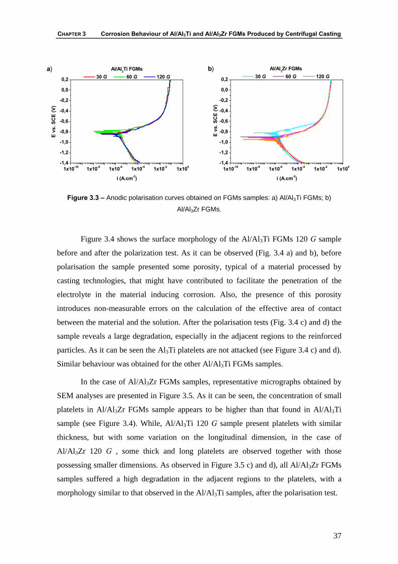
CHAPTER 3 Corrosion Behaviour of Al/Al3Ti and Al/Al3Zr FGMs Produced by Centrifugal Casting
37
1x10⁻¹⁰ 1x10⁻⁸ 1x10⁻⁶ 1x10⁻⁴ 1x10⁻² 1x100-1,4
-1,2
-1,0
-0,8
-0,6
-0,4
-0,2
0,0
0,2
Al/Al3Ti FGMs 30 G 60 G 120 G
E vs
. SC
E (V
)
i (A.cm-2)
a)
1x10⁻¹⁰ 1x10⁻⁸ 1x10⁻⁶ 1x10⁻⁴ 1x10⁻² 1x100-1,4
-1,2
-1,0
-0,8
-0,6
-0,4
-0,2
0,0
0,2
E vs
. SC
E (V
)
i (A.cm-2)
Al/Al3Zr FGMs 30 G 60 G 120 G
b)
Figure 3.3 – Anodic polarisation curves obtained on FGMs samples: a) Al/Al3Ti FGMs; b)
Al/Al3Zr FGMs.
Figure 3.4 shows the surface morphology of the Al/Al3Ti FGMs 120 G sample
before and after the polarization test. As it can be observed (Fig. 3.4 a) and b), before
polarisation the sample presented some porosity, typical of a material processed by
casting technologies, that might have contributed to facilitate the penetration of the
electrolyte in the material inducing corrosion. Also, the presence of this porosity
introduces non-measurable errors on the calculation of the effective area of contact
between the material and the solution. After the polarisation tests (Fig. 3.4 c) and d) the
sample reveals a large degradation, especially in the adjacent regions to the reinforced
particles. As it can be seen the Al3Ti platelets are not attacked (see Figure 3.4 c) and d).
Similar behaviour was obtained for the other Al/Al3Ti FGMs samples.
In the case of Al/Al3Zr FGMs samples, representative micrographs obtained by
SEM analyses are presented in Figure 3.5. As it can be seen, the concentration of small
platelets in Al/Al3Zr FGMs sample appears to be higher than that found in Al/Al3Ti
sample (see Figure 3.4). While, Al/Al3Ti 120 G sample present platelets with similar
thickness, but with some variation on the longitudinal dimension, in the case of
Al/Al3Zr 120 G , some thick and long platelets are observed together with those
possessing smaller dimensions. As observed in Figure 3.5 c) and d), all Al/Al3Zr FGMs
samples suffered a high degradation in the adjacent regions to the platelets, with a
morphology similar to that observed in the Al/Al3Ti samples, after the polarisation test.
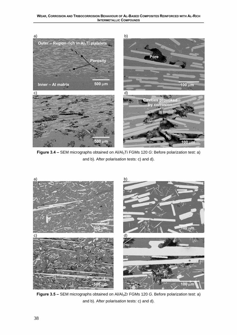
WEAR, CORROSION AND TRIBOCORROSION BEHAVIOUR OF AL-BASED COMPOSITES REINFORCED WITH AL-RICH INTERMETALLIC COMPOUNDS
38
Figure 3.4 – SEM micrographs obtained on Al/Al3Ti FGMs 120 G: Before polarization test: a)
and b). After polarisation tests: c) and d).
a)
b)
c)
d)
Figure 3.5 – SEM micrographs obtained on Al/Al3Zr FGMs 120 G. Before polarization test: a)
and b). After polarisation tests: c) and d).
a)
b)
c) d)
500 μm
Outer – Region rich in Al3Ti platelets Inner – Al matrix
Pore
100 μm
Cavities provoked by corrosion
500 μm 100 μm
Porosity
500 μm
500 μm
100 μm
100 μm
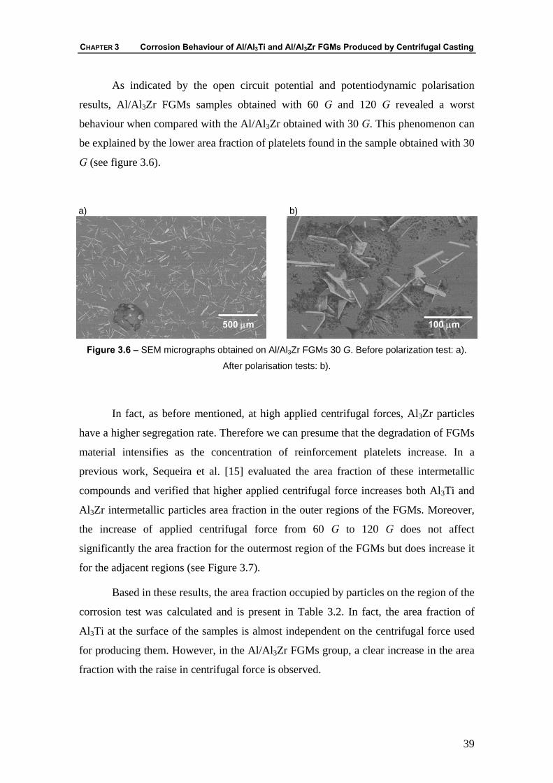
CHAPTER 3 Corrosion Behaviour of Al/Al3Ti and Al/Al3Zr FGMs Produced by Centrifugal Casting
39
As indicated by the open circuit potential and potentiodynamic polarisation
results, Al/Al3Zr FGMs samples obtained with 60 G and 120 G revealed a worst
behaviour when compared with the Al/Al3Zr obtained with 30 G. This phenomenon can
be explained by the lower area fraction of platelets found in the sample obtained with 30
G (see figure 3.6).
a)
b)
Figure 3.6 – SEM micrographs obtained on Al/Al3Zr FGMs 30 G. Before polarization test: a).
After polarisation tests: b).
In fact, as before mentioned, at high applied centrifugal forces, Al3Zr particles
have a higher segregation rate. Therefore we can presume that the degradation of FGMs
material intensifies as the concentration of reinforcement platelets increase. In a
previous work, Sequeira et al. [15] evaluated the area fraction of these intermetallic
compounds and verified that higher applied centrifugal force increases both Al3Ti and
Al3Zr intermetallic particles area fraction in the outer regions of the FGMs. Moreover,
the increase of applied centrifugal force from 60 G to 120 G does not affect
significantly the area fraction for the outermost region of the FGMs but does increase it
for the adjacent regions (see Figure 3.7).
Based in these results, the area fraction occupied by particles on the region of the
corrosion test was calculated and is present in Table 3.2. In fact, the area fraction of
Al3Ti at the surface of the samples is almost independent on the centrifugal force used
for producing them. However, in the Al/Al3Zr FGMs group, a clear increase in the area
fraction with the raise in centrifugal force is observed.
500 μm 100 μm

WEAR, CORROSION AND TRIBOCORROSION BEHAVIOUR OF AL-BASED COMPOSITES REINFORCED WITH AL-RICH INTERMETALLIC COMPOUNDS
40
a) Al/Al3Ti FGMs
0306090120150
0,0 0,5 1,0 0,5 1,0 0,5 1,0
HK
N (300 gf)
Normalized Thichness
60 G 120 G
0,000,050,100,150,200,25
Are
a Fr
actio
n 30 G
b) Al/Al3Zr FGMs
0306090120150
0,0 0,5 1,0 0,5 1,0 0,5 1,0
HK
N (300 gf)
Normalized Thichness
60 G 120 G
0,000,050,100,150,200,25
Are
a Fr
actio
n 30 G
Figure 3.7 – Intermetalic particles area fraction (columns) and Knoop hardness distribution
(lines). The outer of the ring is represented as the position 1,0 of the normalized thickness and
the inner region by the position 0,0 [15].
Table 3.2 – Area fraction occupied by particles on the region of corrosion test.
Al/Al3Ti FGMs Al/Al3Zr FGMs Samples
30 G 60 G 120 G 30 G 60 G 120 G Area fraction 0,17 0,17 0,18 0,13 0,15 0,17
Birbilis et al [2] refer that the corrosion resistance of Al alloys is influenced by
the presence of intermetallic particles exhibiting different electrochemical
characteristics from those of the matrix. When the intermetallic particles are cathodic
relatively to the matrix, as it happens with Al3Ti and Al3Zr, the circumferential pits
appear as a ring of attack around a more or less intact particle. This type of morphology
has been ascribed to localized galvanic attack of the more active matrix by the nobler
particle.
According to Pardo et al [17], pitting attack is reported to be the major form of
corrosion in Al-MMCs. Preferentially, the attack occurs at the reinforcement/matrix
interface. Furthermore, pores, matrix second phases and interfacial reaction products
can all influence corrosion behaviour in a significant way. The addition of a reinforcing
phase could lead to further discontinuities in the film, increasing the number of sites
where corrosion can be initiated and rendering the composite liable to severe attack. On
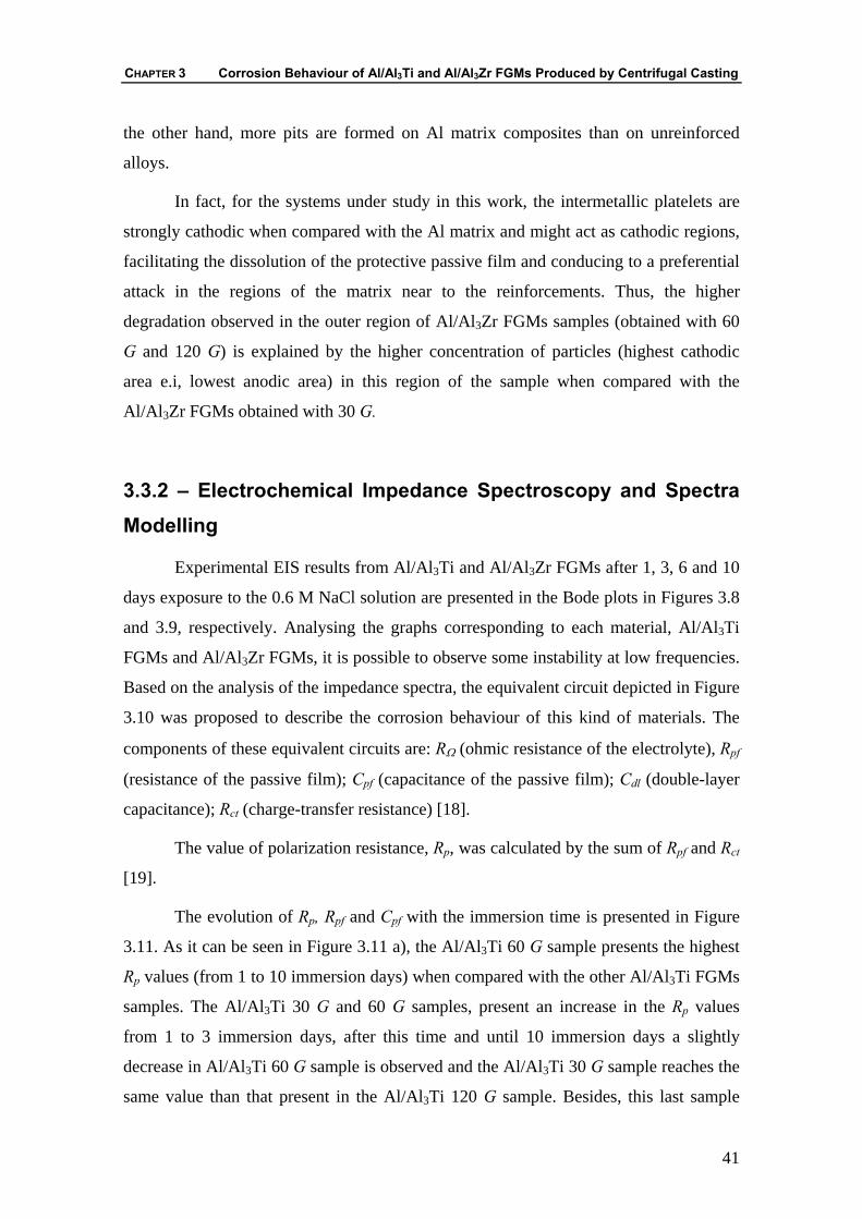
CHAPTER 3 Corrosion Behaviour of Al/Al3Ti and Al/Al3Zr FGMs Produced by Centrifugal Casting
41
the other hand, more pits are formed on Al matrix composites than on unreinforced
alloys.
In fact, for the systems under study in this work, the intermetallic platelets are
strongly cathodic when compared with the Al matrix and might act as cathodic regions,
facilitating the dissolution of the protective passive film and conducing to a preferential
attack in the regions of the matrix near to the reinforcements. Thus, the higher
degradation observed in the outer region of Al/Al3Zr FGMs samples (obtained with 60
G and 120 G) is explained by the higher concentration of particles (highest cathodic
area e.i, lowest anodic area) in this region of the sample when compared with the
Al/Al3Zr FGMs obtained with 30 G.
3.3.2 – Electrochemical Impedance Spectroscopy and Spectra Modelling
Experimental EIS results from Al/Al3Ti and Al/Al3Zr FGMs after 1, 3, 6 and 10
days exposure to the 0.6 M NaCl solution are presented in the Bode plots in Figures 3.8
and 3.9, respectively. Analysing the graphs corresponding to each material, Al/Al3Ti
FGMs and Al/Al3Zr FGMs, it is possible to observe some instability at low frequencies.
Based on the analysis of the impedance spectra, the equivalent circuit depicted in Figure
3.10 was proposed to describe the corrosion behaviour of this kind of materials. The
components of these equivalent circuits are: RΩ (ohmic resistance of the electrolyte), Rpf
(resistance of the passive film); Cpf (capacitance of the passive film); Cdl (double-layer
capacitance); Rct (charge-transfer resistance) [18].
The value of polarization resistance, Rp, was calculated by the sum of Rpf and Rct
[19].
The evolution of Rp, Rpf and Cpf with the immersion time is presented in Figure
3.11. As it can be seen in Figure 3.11 a), the Al/Al3Ti 60 G sample presents the highest
Rp values (from 1 to 10 immersion days) when compared with the other Al/Al3Ti FGMs
samples. The Al/Al3Ti 30 G and 60 G samples, present an increase in the Rp values
from 1 to 3 immersion days, after this time and until 10 immersion days a slightly
decrease in Al/Al3Ti 60 G sample is observed and the Al/Al3Ti 30 G sample reaches the
same value than that present in the Al/Al3Ti 120 G sample. Besides, this last sample
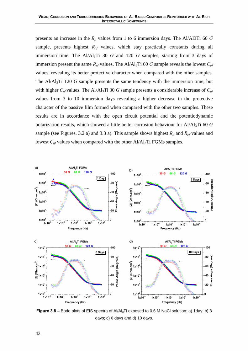
WEAR, CORROSION AND TRIBOCORROSION BEHAVIOUR OF AL-BASED COMPOSITES REINFORCED WITH AL-RICH INTERMETALLIC COMPOUNDS
42
presents an increase in the Rp values from 1 to 6 immersion days. The Al/Al3Ti 60 G
sample, presents highest Rpf values, which stay practically constants during all
immersion time. The Al/Al3Ti 30 G and 120 G samples, starting from 3 days of
immersion present the same Rpf values. The Al/Al3Ti 60 G sample reveals the lowest Cpf
values, revealing its better protective character when compared with the other samples.
The Al/Al3Ti 120 G sample presents the same tendency with the immersion time, but
with higher Cpf values. The Al/Al3Ti 30 G sample presents a considerable increase of Cpf
values from 3 to 10 immersion days revealing a higher decrease in the protective
character of the passive film formed when compared with the other two samples. These
results are in accordance with the open circuit potential and the potentiodynamic
polarization results, which showed a little better corrosion behaviour for Al/Al3Ti 60 G
sample (see Figures. 3.2 a) and 3.3 a). This sample shows highest Rp and Rpf values and
lowest Cpf values when compared with the other Al/Al3Ti FGMs samples.
1x10⁻³ 1x10⁻¹ 1x101 1x10³ 1x1051x100
1x101
1x10²
1x10³
1x10⁴
1x10⁵
0
-20
-40
-60
-80
-100
Frequency (Hz)
Al/Al3Ti FGMs30 G 60 G 120 G
a)
Ph
ase
Ang
le (D
egre
es)
|Z| (
Ohm
.cm
2 )
1 Day
1x10⁻³ 1x10⁻¹ 1x101 1x10³ 1x1051x100
1x101
1x10²
1x10³
1x10⁴
1x10⁵
0
-20
-40
-60
-80
-100
Al/Al3Ti FGMs30 G 60 G 120 G
|Z
| (O
hm.c
m2 )
b)
3 Days
Phas
e A
ngle
(Deg
rees
)
Frequency (Hz)
1x10⁻³ 1x10⁻¹ 1x101 1x10³ 1x1051x100
1x101
1x10²
1x10³
1x10⁴
1x10⁵
0
-20
-40
-60
-80
-1006 Days
Al/Al3Ti FGMs30 G 60 G 120 G
Phas
e A
ngle
(Deg
rees
)
Frequency (Hz)
|Z| (
Ohm
.cm
2 )
c)
1x10⁻³ 1x10⁻¹ 1x101 1x10³ 1x1051x100
1x101
1x10²
1x10³
1x10⁴
1x10⁵
0
-20
-40
-60
-80
-100
Al/Al3Ti FGMs30 G 60 G 120 G
Phas
e A
ngle
(Deg
rees
)
Frequency (Hz)
|Z| (
Ohm
.cm
2 )
d)
10 Days
Figure 3.8 – Bode plots of EIS spectra of Al/Al3Ti exposed to 0.6 M NaCl solution: a) 1day; b) 3
days; c) 6 days and d) 10 days.

CHAPTER 3 Corrosion Behaviour of Al/Al3Ti and Al/Al3Zr FGMs Produced by Centrifugal Casting
43
1x10⁻³ 1x10⁻¹ 1x101 1x10³ 1x1051x100
1x101
1x10²
1x10³
1x10⁴
1x10⁵
0
-20
-40
-60
-80
-100
Phas
e A
ngle
(Deg
rees
)Frequency (Hz)
|Z| (
Ohm
.cm
2 )
1 Day
Al/Al3Zr FGMs30 G 60 G 120 G
a)
1x10⁻³ 1x10⁻¹ 1x101 1x10³ 1x1051x100
1x101
1x10²
1x10³
1x10⁴
1x10⁵
0
-20
-40
-60
-80
-100
b)
3 Days
Al/Al3Zr FGMs30 G 60 G 120 G
Ph
ase
Ang
le (D
egre
es)
Frequency (Hz)
|Z| (
Ohm
.cm
2 )
1x10⁻³ 1x10⁻¹ 1x101 1x10³ 1x1051x100
1x101
1x10²
1x10³
1x10⁴
1x10⁵
0
-20
-40
-60
-80
-1006 Days
Al/Al3Zr FGMs30 G 60 G 120 G
c)
Phas
e A
ngle
(Deg
rees
)
Frequency (Hz)
|Z| (
Ohm
.cm
2 )
1x10⁻³ 1x10⁻¹ 1x101 1x10³ 1x1051x100
1x101
1x10²
1x10³
1x10⁴
1x10⁵
0
-20
-40
-60
-80
-100
10 Days
|Z| (
Ohm
.cm
2 )
Frequency (Hz)
Phas
e A
ngle
(Deg
rees
)
Al/Al3Zr FGMs30 G 60 G 120 G
d)
Figure 3.9 – Bode plots of EIS spectra of Al/Al3Zr exposed to 0.6 M NaCl solution: a) 1day; b) 3
days; c) 6 days and d) 10 days.
Figure 3.10 – Equivalent circuit used for fitting the experimental data and its possible
corresponding physical structure used for the Al/Al3Ti FGMs and Al/Al3Zr FGMs. Equivalent
circuit: (Rpf ) resistance of the passive film; (RΩ ) ohmic resistance of the electrolyte; (Cpf )
capacitance of the passive film; (Cdl) double-layer capacitance; (Rct) charge-transfer resistance.
Pore passive film
RΩ
Rct
Cpf
Rpf
Cdl
Solution Oxide Metal
WEAR, CORROSION AND TRIBOCORROSION BEHAVIOUR OF AL-BASED COMPOSITES REINFORCED WITH AL-RICH INTERMETALLIC COMPOUNDS
44
4,0x10⁻⁵
8,0x10⁻⁵
1,2x10⁻⁴
Immersion time (days)
Cpf (F
.cm
-2)
1 3 6 10
4,0x10³
8,0x10³
1,2x10⁴
Rpf
(Ohm
.cm
2 )
1,5x10⁴
3,0x10⁴
4,5x10⁴
a) Al/Al3Ti FGMs30 G 60 G 120 G
Rp(
Ohm
.cm
2 )
4,0x10⁻⁵
8,0x10⁻⁵
1,2x10⁻⁴
b) Al/Al3Zr FGMs30 G 60 G 120 G
1 3 6 10Immersion time (days)
Cpf
(F.c
m-2)
4,0x10³
8,0x10³
1,2x10⁴
Rpf
(Ohm
.cm
2 )
1,5x10⁴
3,0x10⁴
4,5x10⁴
Rp(O
hm.c
m2 )
Figure 3.11 – Influence of the immersion time on the polarization resistance (Rp), film
polarization resistance (Rpf) and capacitance of the film (Cpf): a) Al/Al3Ti FGMs samples; b)
Al/Al3Zr FGMs samples.
On the other hand, the group of Al/Al3Zr FGMs samples presents an abrupt
decrease in the Rp values from 1 to 3 immersion days. Also, from 3 up to 10 days of
immersion the samples showed a soft decrease of Rp. An exception occurs with the
sample obtained with 60 G, which reveals an increase in the Rp from 3 to 10 days of
immersion time. This can be attributed to the formation of corrosion products inside of
the degraded areas. In this group of samples the Rpf diminish along of the 10 days of
immersion for all samples, indicating the degradation of passive film. This phenomenon
is corroborated by the evolution of the Cpf in all Al/Al3Zr FGMs samples, which
increase monotonically with the immersion time. The lowest Cpf values found in 30 G
sample is a indication of the better corrosion behaviour of this sample, as indicated in
the open circuit potential and potentiodynamic polarisation test.
CHAPTER 3 Corrosion Behaviour of Al/Al3Ti and Al/Al3Zr FGMs Produced by Centrifugal Casting
45
3.4 – Conclusions
In the present study, the corrosion behaviour of Al/Al3Ti and Al/Al3Zr FGMs,
when immersed in 0.6 M NaCl solution, at different immersion times (1, 3, 6 and 10
days) was investigated:
1) The electrochemical behaviour of FGMs samples showed that galvanic effects
between the intermetallic particles and the metal matrix affect the overall corrosion
resistance of FGMs;
2) In case of Al/Al3Ti FGMs group, the samples obtained with 60 G present the
better corrosion resistance. In case of Al/Al3Zr FGMs group, sample obtained with 30 G
revealed better behaviour when compared with the obtained with 60 G and 120 G;
3) In general terms this behaviour can be associated to the particles segregation
level, i. e., when a low segregation of particles is found in the material, associated to
low applied centrifugal forces, the corrosion resistance of FGM appear to increase.
Acknowledgements
The authors gratefully acknowledge the financial support provided by 21st COE
Research of the Ministry of Education Culture, Sports Science and Technology of
Japan. Acknowledgments also to “FCT”, Portugal, through the project
SFRH/BPD/5518/2001.
3.5 – References
[1] C. Gouveia-Caridade, M.I.S. Pereira, C.M. A. Brett, Electrochemical Acta 49
(2004) 785.
[2] N. Birbilis, R.G. Buchheit, Journal of The Electrochemical Society 152 (2005)
140.
[3] M.V. Karpets, Yu.V. Milman, O.M. Barabash, N.P. Korzhova, O.N. Senkov,
D.B. Miracle, T.N. Legkaya, I.V. Voskoboynik, Intermetallics 11 (2003) 241.
[4] K.I. Moon, S.C. Kim, K.S. Lee, Intermetallics 10 (2002) 185.
WEAR, CORROSION AND TRIBOCORROSION BEHAVIOUR OF AL-BASED COMPOSITES REINFORCED WITH AL-RICH INTERMETALLIC COMPOUNDS
46
[5] A. Aballe, M. Bethencourt, F.J. Botana, M.J. Cano, M. Marcos, Corrosion
Science 45 (2003) 161.
[6] A. Barbucci, G. Bruzzone, M. Delucchi, M. Panizza, G. Cerisola, Intermetallics
8 (2000) 305.
[7] Y. Fukui, JSME International Journal 34 (1991)144.
[8] Y. Watanabe, Y. Yamanaka, Y. Fukui, Zeitschrift für Metallkde 88 (1997) 717.
[9] Y. Watanabe, N. Yamanaka, Y. Fukui, Metallurgical and Materials Transactions
A (1999) 3253.
[10] Y. Watanabe, Y. Fukui, Recent Res. Devel. Metallurg. & Materials Sci. 4 (2000)
51.
[11] Y. Watanabe, Y. Fukui, Aluminium Transactions 2 (2000)195.
[12] Y. Watanabe, T. Nakamura, Intermetallics 9 (2001) 33.
[13] Y. Watanabe, H. Eryu, K. Matsuura, Acta Materialia 49 (2001) 775.
[14] Y. Watanabe, A. Kawamoto, K. Matsuura, Compositesa Science and
Technology 62 (2002) 881.
[15] P.D. Sequeira, Y. Watanabe, L.A. Rocha, Proceedings of the 8th International
Symposium on Multifunctional and Functionally Graded Materials, Trans Tech
Publication, Leuven, 2004, p. 609.
[16] P.D. Sequeira, Y. Watanabe, L.A. Rocha, 2nd International Conference on
Texture and Anisotropy of Polycrystals, Metz, 2004.
[17] A. Pardo, M.C. Merino, S. Merino, F. Viejo, M. Carboneras, R. Arrabal,
Corrosion Science 47 (2005) 1750.
[18] J.E.G. González, J.G. Mirza-Rosca, Journal of Electroanalytical Chemistry 471
(1999) 109.
[19] C. Liu, A. Leyland, Q. Bi and A. Mattehews, Surface and Coating Technology
141 (2001) 164.
CHAPTER 4 Microstructural Characterization and Tribocorrosion Behaviour of Al/Al3Ti and Al/Al3Zr FGMs
47
CHAPTER 4
Microstructural Characterization and Tribocorrosion Behaviour of Al/Al3Ti and Al/Al3Zr
FGMs
P.D. Sequeira a,b, S.C. Ferreira a, Y. Watanabe b, L.A. Rocha a,c, E. Ariza a, J. R. Gomes a,c
aResearch Centre on Interfaces and Surface Performance, University of Minho, Campus de
Azurém, 4800-058 Guimarães, Portugal
bDepartment of Engineering Physics, Electronics and Mechanics, Graduate School of
Engineering, Nagoya Institute of Technology, Gokiso-Chu, Showa-Ku, 466-8555 Nagoya, Japan
cDepartment of Mechanical Engineering, University of Minho, Campus de Azurém, 4800-058
Guimarães, Portugal
Abstract
Al/Al3Ti and Al/Al3Zr functionally graded materials (FGMs) are manufactured
through a centrifugal method from Al-5 mass % Ti and Al-5 mass % Zr, respectively.
Applied centrifugal forces were 30, 60 and 120 G (units of gravity). Microstructural
characterization was performed to evaluate intermetallic particles volume fraction and
orientation distributions. The influence of the reinforcing phase on the tribocorrosion
behaviour of the FGMs was investigated. An increase in both the intermetallic particles
volume fraction as well as their orientation in the outer regions of the FGMs was found
as the applied centrifugal force increased. Al3Ti particles were found to have a higher
segregation rate with lower applied centrifugal forces than the Al3Zr particles; a
WEAR, CORROSION AND TRIBOCORROSION BEHAVIOUR OF AL-BASED COMPOSITES REINFORCED WITH AL-RICH INTERMETALLIC COMPOUNDS
48
situation that was reversed for higher applied centrifugal forces. Better tribocorrosion
behaviour was found in the samples containing the highest concentration of reinforcing
particles.
Keywords: Trialuminide Intermetallics; Functionally Graded Materials (FGMs);
Tribocorrosion.
4.1 – Introduction
Dispersion of hard intermetallic compounds in Al alloys has been studied as a
means to improve the alloys’ mechanical properties [1-4].
When the reinforcing phase has a higher density than the matrix, the centrifugal
method is attractive due to the fact that there is a selective reinforcement of the surface
of the component while gradually increasing the relative amount of ductile phases
towards the inner region. This results in a higher wear resistance in the surface as well
as maintaining high bulk toughness [5-8]. In fact, the presence of the reinforcing phase,
in this case Al3Ti or Al3Zr platelets, has a strong influence on the local mechanical
properties. The shape, size and spatial orientation of the reinforcing phase will also play
an essential role on the wear performance of the material [9-13].
As stated above, particle segregation during casting with the centrifugal method
occurs due to the difference in density between the particles and molten alloy [14],
therefore, the study of two Al/intermetallic compounds systems where the intermetallic
compounds have different density values, Al3Ti and Al3Zr have densities of 3.4 and 4.1
g.cm-3, respectively, is of interest.
There are some published works dealing, independently, on the wear or
corrosion behaviour of composites reinforced with intermetallic particles, however, no
studies were published on the tribocorrosion behaviour of this kind of materials when
they are in contact with aggressive environments. The tribocorrosion behaviour of the
Al/Al3Ti and Al/Al3Zr FGMs is important to evaluate, once that, the particulate
reinforced aluminum matrix composites (AlMCp) have received increasing demands for
aerospace and automotive applications [15]. Compared to ceramic reinforcements, the
employement of intermetallics as mechanical resistant reinforcement has advantages. In
CHAPTER 4 Microstructural Characterization and Tribocorrosion Behaviour of Al/Al3Ti and Al/Al3Zr FGMs
49
addition to their high level of hardness, elastic modulus, melting temperature and
thermal stability, the thermal expansion coefficients of intermetallics is much closer to
those of Al alloys. The smaller discrepancy in thermal expansion coefficients will
decrese the residual stress at reinforcement/matrix interfaces when the composite is
exposed to thermal cycles, hence guarantying a lower degree of failure originated at the
interface [16].
The material exposed to a tribocorrosion environment, i. e. where interactions
between mechanical and corrosion degradation processes occur, suffers an irreversible
transformation leading to decrease of the performance of that material [17]. The total
metal removal rate is usually not simply the sum of the corrosion rate and the wear rate
measured in separate experiments. In many cases corrosion is accelerated by wear and
similarly, wear may be accelerated by corrosion [18]. The mutual dependence of
mechanical and chemical metal removal rates in a tribocorrosion system can be due to
phenomena as: local abrasion of the passive film can lead to wear accelerated corrosion
due to rapid dissolution of the locally depassivated metal surface, followed by
repassivation; the abrasive action of hard oxide particles formed by corrosion can
accelerate the mechanical metal removal by wear; the plastic deformation of the surface
layer of a rubbing metal can lead to transfer of material to the opposite body resulting in
a reduction of the corrosive, and others [17-19].
In the present study microstructural characterization was performed on Al/Al3Zr
and Al/Al3Ti FGMs processed with different applied centrifugal forces. Also
tribocorrosion behaviour of Al/Al3Ti and Al/Al3Zr FGMs has been studied in the outer
region of the FGMs. Results indicate that an increase in the applied centrifugal forces
increases both the particles’ volume fraction as well as their orientation in the outer
regions of the fabricated FGM rings. Also for lower applied centrifugal forces the Al3Ti
particles migrate faster than the Al3Zr particles, a situation that is reversed for higher
applied centrifugal forces. Higher tribocorrosion resistance was found for the samples
produced with higher centrifugal force.
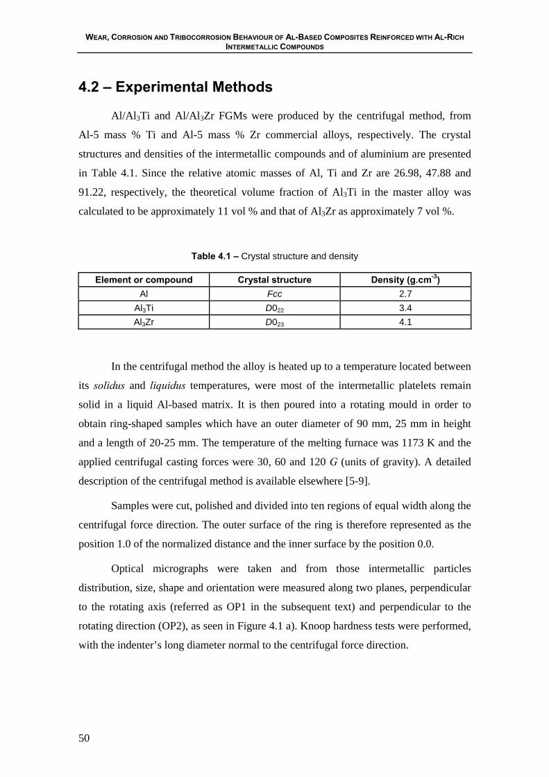
WEAR, CORROSION AND TRIBOCORROSION BEHAVIOUR OF AL-BASED COMPOSITES REINFORCED WITH AL-RICH INTERMETALLIC COMPOUNDS
50
4.2 – Experimental Methods
Al/Al3Ti and Al/Al3Zr FGMs were produced by the centrifugal method, from
Al-5 mass % Ti and Al-5 mass % Zr commercial alloys, respectively. The crystal
structures and densities of the intermetallic compounds and of aluminium are presented
in Table 4.1. Since the relative atomic masses of Al, Ti and Zr are 26.98, 47.88 and
91.22, respectively, the theoretical volume fraction of Al3Ti in the master alloy was
calculated to be approximately 11 vol % and that of Al3Zr as approximately 7 vol %.
Table 4.1 – Crystal structure and density
Element or compound Crystal structure Density (g.cm-3) Al Fcc 2.7
Al3Ti D022 3.4 Al3Zr D023 4.1
In the centrifugal method the alloy is heated up to a temperature located between
its solidus and liquidus temperatures, were most of the intermetallic platelets remain
solid in a liquid Al-based matrix. It is then poured into a rotating mould in order to
obtain ring-shaped samples which have an outer diameter of 90 mm, 25 mm in height
and a length of 20-25 mm. The temperature of the melting furnace was 1173 K and the
applied centrifugal casting forces were 30, 60 and 120 G (units of gravity). A detailed
description of the centrifugal method is available elsewhere [5-9].
Samples were cut, polished and divided into ten regions of equal width along the
centrifugal force direction. The outer surface of the ring is therefore represented as the
position 1.0 of the normalized distance and the inner surface by the position 0.0.
Optical micrographs were taken and from those intermetallic particles
distribution, size, shape and orientation were measured along two planes, perpendicular
to the rotating axis (referred as OP1 in the subsequent text) and perpendicular to the
rotating direction (OP2), as seen in Figure 4.1 a). Knoop hardness tests were performed,
with the indenter’s long diameter normal to the centrifugal force direction.
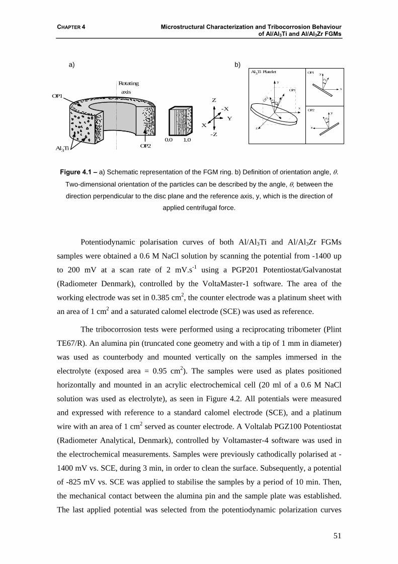
CHAPTER 4 Microstructural Characterization and Tribocorrosion Behaviour of Al/Al3Ti and Al/Al3Zr FGMs
51
a) b)
Rotating
axis
Al3Ti0.0 1.0
-X
Z
-Z
XY
OP1
OP2
Al3Ti Platelet
y
x
z
OP1
OP2
θ1θ2
x
θ1
yOP1
y
θ2
OP2
z
Figure 4.1 – a) Schematic representation of the FGM ring. b) Definition of orientation angle, θ.
Two-dimensional orientation of the particles can be described by the angle, θ, between the
direction perpendicular to the disc plane and the reference axis, y, which is the direction of
applied centrifugal force.
Potentiodynamic polarisation curves of both Al/Al3Ti and Al/Al3Zr FGMs
samples were obtained a 0.6 M NaCl solution by scanning the potential from -1400 up
to 200 mV at a scan rate of 2 mV.s-1 using a PGP201 Potentiostat/Galvanostat
(Radiometer Denmark), controlled by the VoltaMaster-1 software. The area of the
working electrode was set in 0.385 cm2, the counter electrode was a platinum sheet with
an area of 1 cm2 and a saturated calomel electrode (SCE) was used as reference.
The tribocorrosion tests were performed using a reciprocating tribometer (Plint
TE67/R). An alumina pin (truncated cone geometry and with a tip of 1 mm in diameter)
was used as counterbody and mounted vertically on the samples immersed in the
electrolyte (exposed area = 0.95 cm2). The samples were used as plates positioned
horizontally and mounted in an acrylic electrochemical cell (20 ml of a 0.6 M NaCl
solution was used as electrolyte), as seen in Figure 4.2. All potentials were measured
and expressed with reference to a standard calomel electrode (SCE), and a platinum
wire with an area of 1 cm2 served as counter electrode. A Voltalab PGZ100 Potentiostat
(Radiometer Analytical, Denmark), controlled by Voltamaster-4 software was used in
the electrochemical measurements. Samples were previously cathodically polarised at -
1400 mV vs. SCE, during 3 min, in order to clean the surface. Subsequently, a potential
of -825 mV vs. SCE was applied to stabilise the samples by a period of 10 min. Then,
the mechanical contact between the alumina pin and the sample plate was established.
The last applied potential was selected from the potentiodynamic polarization curves

WEAR, CORROSION AND TRIBOCORROSION BEHAVIOUR OF AL-BASED COMPOSITES REINFORCED WITH AL-RICH INTERMETALLIC COMPOUNDS
52
and was used during and after the sliding time. The reciprocating wear test was
performed with a normal load of 3 N, displacement amplitude of 2 mm and a frequency
of 1 Hz. The sliding time was 900 s. When sliding was stopped, the pin and the sample
were removed from the solution and ultrasonically cleaned in ethanol. For each sample
the tests were repeated twice. The total wear volume, caused by the contribution of wear
and corrosion, was determined by a profilometer method, using a Perthometer S5P
roughness meter, by calculating the average of the cross-sectional area multiplied by the
stroke length. The chemical wear volume (Vchem) was determined from measured
current, using Faraday’s law:
ρ⋅⋅⋅
=Fn
MQV chem (4.1)
where, Q is the electric charge, which is obtained by integrating of the current density
curve with the time, along of the sliding time ( ∫= dtIQ ), M is the atomic mass of
aluminium (27 g.mol-1), n the valence of dissolution of the aluminium (+3), F the
Faraday’s constant (9.649⋅10-4 C.mol-1) and ρ is the density of the aluminium (2.7⋅10-3
g.mm-3). The mechanical wear volume, which is the volume of material removed
mechanically, was obtained by subtraction of the calculated chemical wear volume to
the total wear volume.
Figure 4.2 – Schematic view of the electrochemical cell used in the tribocorrosion tests: (1)
Reference electrode, (2) Auxiliary electrode, (3) Alumina pin, (4) Acrylic recipient, (5)
Electrolyte, (6) Working electrode (sample), (7) Tribometer.
2 mm, 1 Hz
F = 3 N
1 2
3 4 5 6 7
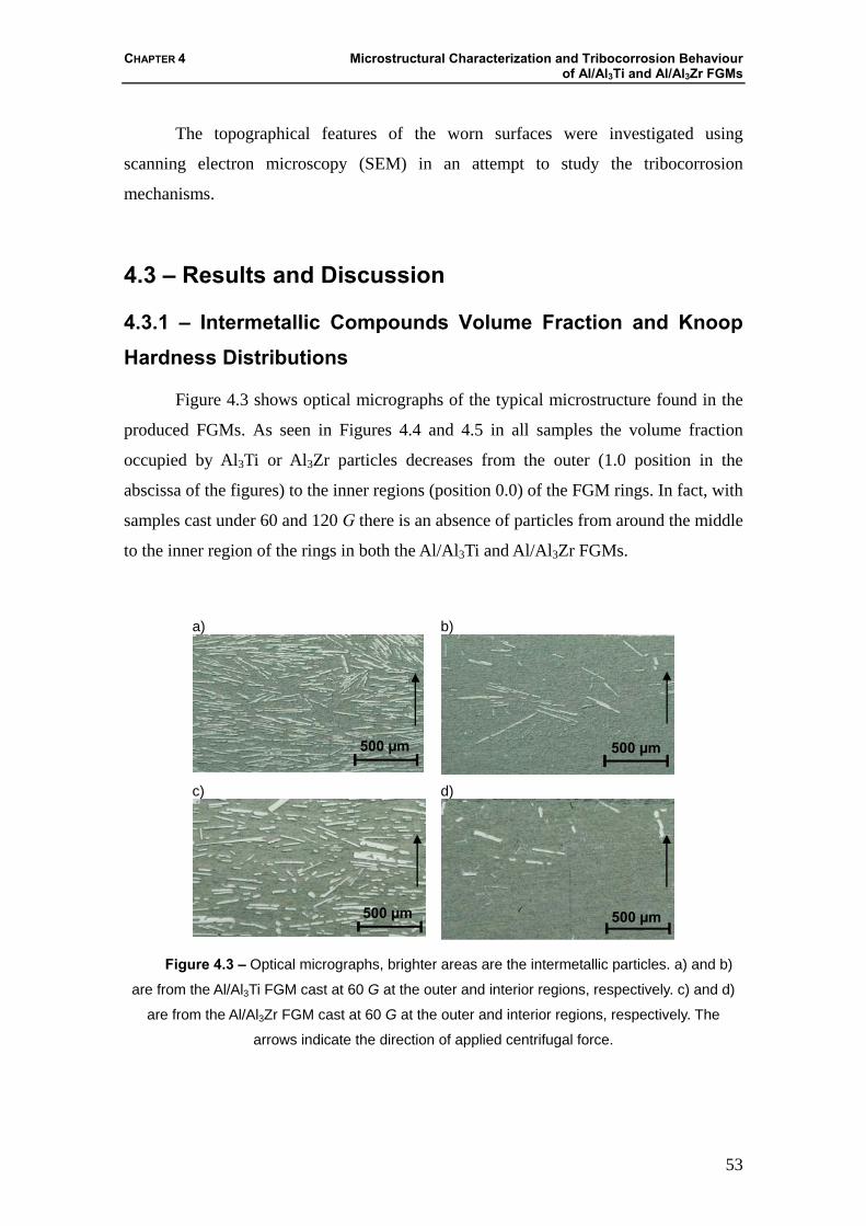
CHAPTER 4 Microstructural Characterization and Tribocorrosion Behaviour of Al/Al3Ti and Al/Al3Zr FGMs
53
The topographical features of the worn surfaces were investigated using
scanning electron microscopy (SEM) in an attempt to study the tribocorrosion
mechanisms.
4.3 – Results and Discussion
4.3.1 – Intermetallic Compounds Volume Fraction and Knoop Hardness Distributions
Figure 4.3 shows optical micrographs of the typical microstructure found in the
produced FGMs. As seen in Figures 4.4 and 4.5 in all samples the volume fraction
occupied by Al3Ti or Al3Zr particles decreases from the outer (1.0 position in the
abscissa of the figures) to the inner regions (position 0.0) of the FGM rings. In fact, with
samples cast under 60 and 120 G there is an absence of particles from around the middle
to the inner region of the rings in both the Al/Al3Ti and Al/Al3Zr FGMs.
a)
b)
c) d)
Figure 4.3 – Optical micrographs, brighter areas are the intermetallic particles. a) and b)
are from the Al/Al3Ti FGM cast at 60 G at the outer and interior regions, respectively. c) and d)
are from the Al/Al3Zr FGM cast at 60 G at the outer and interior regions, respectively. The
arrows indicate the direction of applied centrifugal force.
500 µm 500 µm
500 µm 500 µm
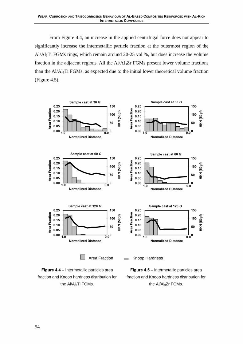
WEAR, CORROSION AND TRIBOCORROSION BEHAVIOUR OF AL-BASED COMPOSITES REINFORCED WITH AL-RICH INTERMETALLIC COMPOUNDS
54
From Figure 4.4, an increase in the applied centrifugal force does not appear to
significantly increase the intermetallic particle fraction at the outermost region of the
Al/Al3Ti FGMs rings, which remain around 20-25 vol %, but does increase the volume
fraction in the adjacent regions. All the Al/Al3Zr FGMs present lower volume fractions
than the Al/Al3Ti FGMs, as expected due to the initial lower theoretical volume fraction
(Figure 4.5).
0.000.050.100.150.200.25
Normalized Distance
Are
a Fr
actio
n
0
50
100
150
HK
N (5
0gf)
0.000.050.100.150.200.25
Normalized Distance
Are
a Fr
actio
n0
50
100
150
HK
N (5
0gf)
0.000.050.100.150.200.25
Normalized Distance
Are
a Fr
actio
n
0
50
100
150
HK
N (5
0gf)
0.000.050.100.150.200.25
Normalized Distance
Are
a Fr
actio
n
0
50
100
150
HK
N (5
0gf)
0.000.050.100.150.200.25
Normalized Distance
Are
a Fr
actio
n
0
50
100
150
HK
N (5
0gf)
0.000.050.100.150.200.25
Normalized Distance
Are
a Fr
actio
n
0
50
100
150
HK
N (5
0gf)
Area Fraction Knoop Hardness
Figure 4.4 – Intermetallic particles area
fraction and Knoop hardness distribution for
the Al/Al3Ti FGMs.
Figure 4.5 – Intermetallic particles area
fraction and Knoop hardness distribution for
the Al/Al3Zr FGMs.
Sample cast at 30 G
1.0 0.0
Sample cast at 30 G
1.0 0.0
Sample cast at 60 G
1.0 0.0
Sample cast at 60 G
1.0 0.0
Sample cast at 120 G
1.0 0.0
Sample cast at 120 G
1.0 0.0

CHAPTER 4 Microstructural Characterization and Tribocorrosion Behaviour of Al/Al3Ti and Al/Al3Zr FGMs
55
At applied centrifugal force of 30 G the Al/Al3Zr FGM exhibits a very low
gradient when compared to the Al/Al3Ti sample. The samples from both systems cast at
60 G display a very similar trend while, for the samples subjected to a centrifugal force
of 120 G, a higher relative clustering of particles on the outermost regions is found for
the Al/Al3Zr FGM.
Al3Ti particles have a higher segregation rate with lower applied centrifugal
forces than the Al3Zr particles; a situation that is reversed for higher applied centrifugal
forces.
It has been accepted, in general, that the viscosity of a suspension rises with to
the increase in number of particles in the suspension. Since the motion of spherical
particles in a viscous liquid under a centrifugal force can be determined by the simple
Stokes' law, the volume fraction gradient within the spherical particle reinforced FGM
becomes steeper by decreasing the mean volume fraction of particles [7]. Easier
migration of the particles in sparser suspensions, compared with denser suspensions,
could not explain the lower gradient obtained in the Al/Al3Zr FGMs at low applied
centrifugal force when compared to the Al/Al3Ti FGMs. In this way, the present results,
relating to the effect of mean volume fraction, contradicts the previous results for
spherical particles [7]. On the other hand the same effect has been found to occur in
Al/Al3Ti FGMs with different volume fraction of particles, that is, an increase in
volume fraction leads to steeper gradients [6]. Therefore it is apparent that the simple
Stokes' law is not applicable to the Al/Al3Ti and Al/Al3Zr systems.
Knoop hardness measurements for the Al/Al3Ti FGMs (Figure 4.4) in general
follow the same trend as the area fraction for each sample, with values around 50 HKN
in the regions without particles and over 100 in areas with the higher intermetallic
content. A similar trend is also observed in the Al/Al3Zr FGMs (Figure 4.5).
4.3.2 – Orientation Distribution of Al3Zr and Al3Ti Platelets
As mentioned above, it was found that in the outer region of the ring, most of
platelets are oriented with their planes nearly perpendicular to the radial direction. In
order to describe the degree of orientation let us define the reference axes, x, y and z, as
shown in Figure 4.1. Planes OP1, OP2 and OP3 correspond to x-y plane, y-z plane and

WEAR, CORROSION AND TRIBOCORROSION BEHAVIOUR OF AL-BASED COMPOSITES REINFORCED WITH AL-RICH INTERMETALLIC COMPOUNDS
56
z-x plane, respectively. Figure 4.1 b) shows the definition of the orientation angles θ1
and θ2 on the Planes OP1 and OP2, respectively. Two-dimensional (2-D) orientation of
the platelet can be described by the angle, θ, between the direction perpendicular to the
disc plane and the reference axis, y, (the centrifugal force direction, i.e. radial direction
of the ring as shown in Figure 4.1a). The 2-D platelet orientation distributions are
obtained from micrographs. Furthermore, in order to describe this orientation tendency
quantitatively, the following Hermans orientation parameter, fp [20,21] was calculated.
fp = [ 2 ⟨cos2θ⟩ -1] (4.2)
Where the trigonometric average is,
⟨cos2θ⟩ = θθθπ
π
dn )(cos2
2
2∫−
(4.3)
The term n(θ) is the orientation distribution function which specifies the fraction
of platelets within the angular element dθ. The parameter fp becomes 0 for a random
distribution of platelets, and it becomes 1 for perfect alignments of the platelets with
their planes perpendicular to the direction of the applied centrifugal force. Intermediate
values of this parameter correspond to partial states of orientation. Negative value of fp
indicates the alignment with their planes parallel to the direction of the applied
centrifugal force.
As seen in Figures 4.6 and 4.7 the platelets tend to be oriented normal to the
centrifugal force direction. The trend is similar along both observation planes (OP1 and
OP2), with exception of the Al/Al3Zr sample cast under 30 G. Also the orientation of
platelets in the outer regions is increased with the increase in applied centrifugal force,
although, as with the volume fraction values, the increase of applied centrifugal force
from 60 to 120 G does not affect significantly the orientation parameter for the
outermost region but does increase it for the adjacent regions, a similar effect is
observed for the Al/Al3Zr FGMs. Also higher orientation parameter values are obtained
for the Al/Al3Ti FGMs. The higher volume fraction of Al3Ti platelets leads to the
necessity of a closer packing between them, which is facilitated by their shape and size
(see Figure 4.3). As for the behaviour of the Al3Zr platelets, a very low orientation
parameter is found in the outer regions of the sample cast under 30 G and an essentially
random orientation in the interior regions. The low particle orientation in this sample is
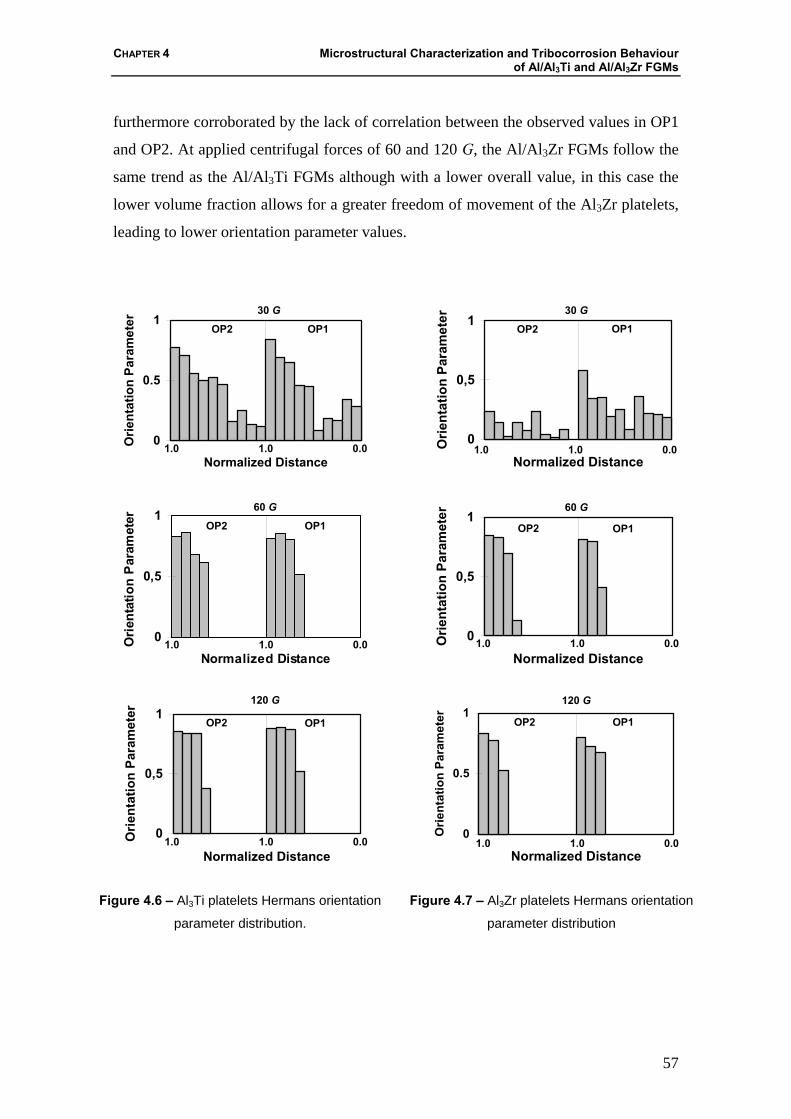
CHAPTER 4 Microstructural Characterization and Tribocorrosion Behaviour of Al/Al3Ti and Al/Al3Zr FGMs
57
furthermore corroborated by the lack of correlation between the observed values in OP1
and OP2. At applied centrifugal forces of 60 and 120 G, the Al/Al3Zr FGMs follow the
same trend as the Al/Al3Ti FGMs although with a lower overall value, in this case the
lower volume fraction allows for a greater freedom of movement of the Al3Zr platelets,
leading to lower orientation parameter values.
0
0.5
1
Normalized Distance
Orie
ntat
ion
Para
met
er
0
0,5
1
Normalized Distance
Orie
ntat
ion
Par
amet
er
0
0,5
1
Normalized Distance
Orie
ntat
ion
Para
met
er
0
0,5
1
Normalized DistanceO
rient
atio
n Pa
ram
eter
0
0,5
1
Normalized Distance
Orie
ntat
ion
Para
met
er
0
0.5
1
Normalized Distance
Orie
ntat
ion
Para
met
er
Figure 4.6 – Al3Ti platelets Hermans orientation
parameter distribution.
Figure 4.7 – Al3Zr platelets Hermans orientation
parameter distribution
30 G
60 G
1.0 1.0 0.0
OP2 OP1
120 G
OP2 OP1
1.0 1.0 0.0
1.0 1.0 0.0
OP2 OP1
30 G
1.0 1.0 0.0
OP2 OP1
60 G
1.0 1.0 0.0
OP2 OP1
120 G
1.0 1.0 0.0
OP2 OP1
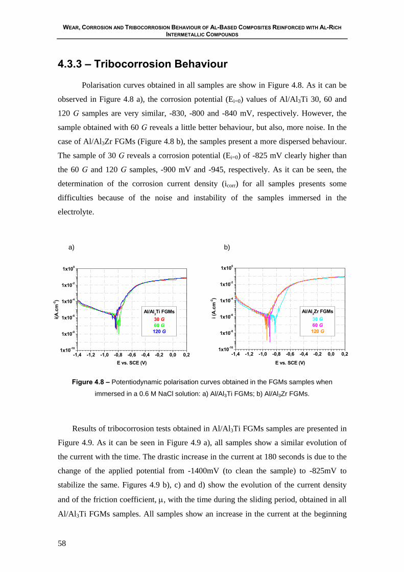
WEAR, CORROSION AND TRIBOCORROSION BEHAVIOUR OF AL-BASED COMPOSITES REINFORCED WITH AL-RICH INTERMETALLIC COMPOUNDS
58
4.3.3 – Tribocorrosion Behaviour
Polarisation curves obtained in all samples are show in Figure 4.8. As it can be
observed in Figure 4.8 a), the corrosion potential (Ei=0) values of Al/Al3Ti 30, 60 and
120 G samples are very similar, -830, -800 and -840 mV, respectively. However, the
sample obtained with 60 G reveals a little better behaviour, but also, more noise. In the
case of Al/Al3Zr FGMs (Figure 4.8 b), the samples present a more dispersed behaviour.
The sample of 30 G reveals a corrosion potential (Ei=0) of -825 mV clearly higher than
the 60 G and 120 G samples, -900 mV and -945, respectively. As it can be seen, the
determination of the corrosion current density (icorr) for all samples presents some
difficulties because of the noise and instability of the samples immersed in the
electrolyte.
a) b)
1x10⁻¹⁰
1x10⁻⁸
1x10⁻⁶
1x10⁻⁴
1x10⁻²
1x100
-1,4 -1,2 -1,0 -0,8 -0,6 -0,4 -0,2 0,0 0,2
Al/Al3Ti FGMs30 G60 G120 G
E vs. SCE (V)
i(A.c
m-2)
1x10⁻¹⁰
1x10⁻⁸
1x10⁻⁶
1x10⁻⁴
1x10⁻²
1x100
-1,4 -1,2 -1,0 -0,8 -0,6 -0,4 -0,2 0,0 0,2
Al/Al3Zr FGMs30 G60 G120 G
E vs. SCE (V)
i (A
.cm
-2)
Figure 4.8 – Potentiodynamic polarisation curves obtained in the FGMs samples when
immersed in a 0.6 M NaCl solution: a) Al/Al3Ti FGMs; b) Al/Al3Zr FGMs.
Results of tribocorrosion tests obtained in Al/Al3Ti FGMs samples are presented in
Figure 4.9. As it can be seen in Figure 4.9 a), all samples show a similar evolution of
the current with the time. The drastic increase in the current at 180 seconds is due to the
change of the applied potential from -1400mV (to clean the sample) to -825mV to
stabilize the same. Figures 4.9 b), c) and d) show the evolution of the current density
and of the friction coefficient, μ, with the time during the sliding period, obtained in all
Al/Al3Ti FGMs samples. All samples show an increase in the current at the beginning
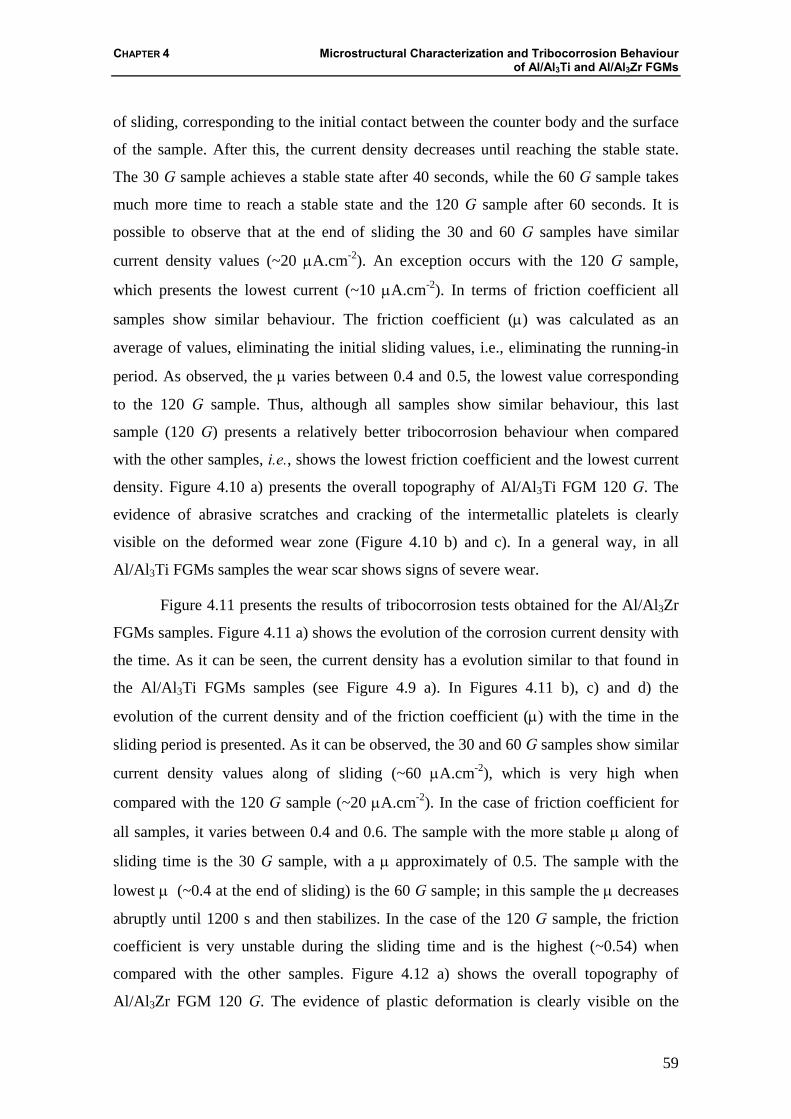
CHAPTER 4 Microstructural Characterization and Tribocorrosion Behaviour of Al/Al3Ti and Al/Al3Zr FGMs
59
of sliding, corresponding to the initial contact between the counter body and the surface
of the sample. After this, the current density decreases until reaching the stable state.
The 30 G sample achieves a stable state after 40 seconds, while the 60 G sample takes
much more time to reach a stable state and the 120 G sample after 60 seconds. It is
possible to observe that at the end of sliding the 30 and 60 G samples have similar
current density values (~20 μA.cm-2). An exception occurs with the 120 G sample,
which presents the lowest current (~10 μA.cm-2). In terms of friction coefficient all
samples show similar behaviour. The friction coefficient (μ) was calculated as an
average of values, eliminating the initial sliding values, i.e., eliminating the running-in
period. As observed, the μ varies between 0.4 and 0.5, the lowest value corresponding
to the 120 G sample. Thus, although all samples show similar behaviour, this last
sample (120 G) presents a relatively better tribocorrosion behaviour when compared
with the other samples, i.e., shows the lowest friction coefficient and the lowest current
density. Figure 4.10 a) presents the overall topography of Al/Al3Ti FGM 120 G. The
evidence of abrasive scratches and cracking of the intermetallic platelets is clearly
visible on the deformed wear zone (Figure 4.10 b) and c). In a general way, in all
Al/Al3Ti FGMs samples the wear scar shows signs of severe wear.
Figure 4.11 presents the results of tribocorrosion tests obtained for the Al/Al3Zr
FGMs samples. Figure 4.11 a) shows the evolution of the corrosion current density with
the time. As it can be seen, the current density has a evolution similar to that found in
the Al/Al3Ti FGMs samples (see Figure 4.9 a). In Figures 4.11 b), c) and d) the
evolution of the current density and of the friction coefficient (μ) with the time in the
sliding period is presented. As it can be observed, the 30 and 60 G samples show similar
current density values along of sliding (~60 μA.cm-2), which is very high when
compared with the 120 G sample (~20 μA.cm-2). In the case of friction coefficient for
all samples, it varies between 0.4 and 0.6. The sample with the more stable μ along of
sliding time is the 30 G sample, with a μ approximately of 0.5. The sample with the
lowest μ (~0.4 at the end of sliding) is the 60 G sample; in this sample the μ decreases
abruptly until 1200 s and then stabilizes. In the case of the 120 G sample, the friction
coefficient is very unstable during the sliding time and is the highest (~0.54) when
compared with the other samples. Figure 4.12 a) shows the overall topography of
Al/Al3Zr FGM 120 G. The evidence of plastic deformation is clearly visible on the
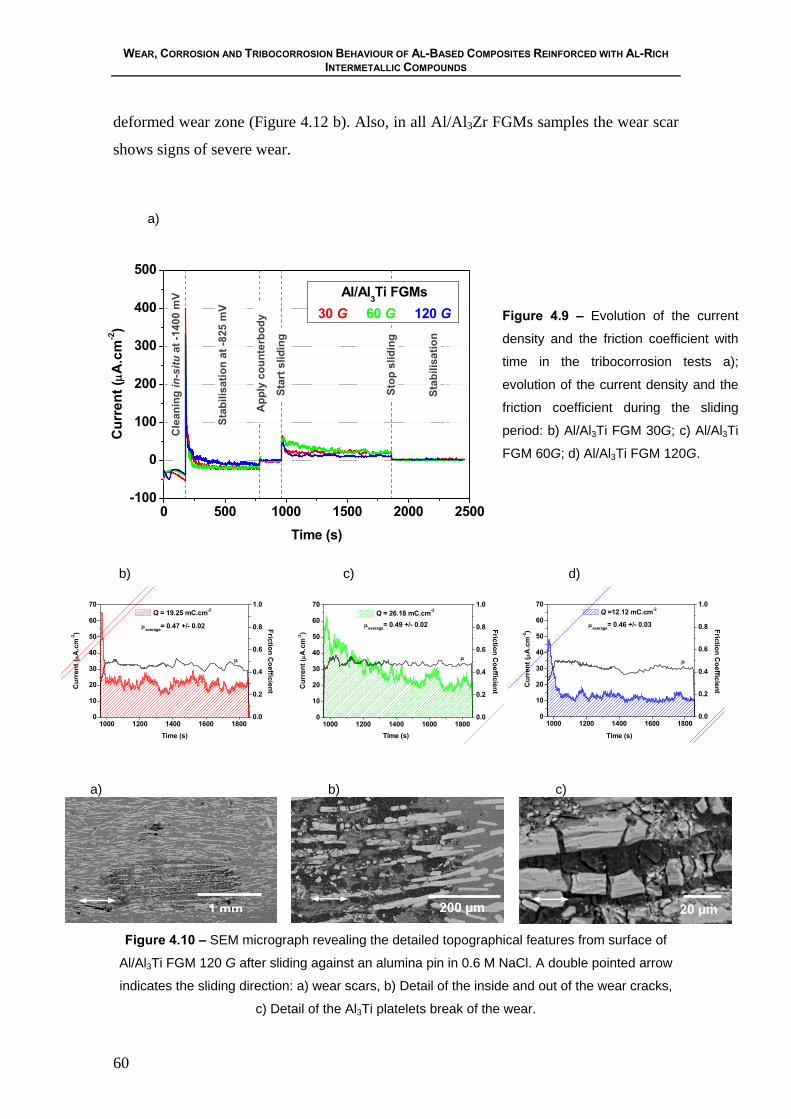
WEAR, CORROSION AND TRIBOCORROSION BEHAVIOUR OF AL-BASED COMPOSITES REINFORCED WITH AL-RICH INTERMETALLIC COMPOUNDS
60
deformed wear zone (Figure 4.12 b). Also, in all Al/Al3Zr FGMs samples the wear scar
shows signs of severe wear.
a)
0 500 1000 1500 2000 2500-100
0
100
200
300
400
500
Stab
ilisa
tion
Cur
rent
(μA
.cm
-2)
Time (s)
Al/Al3Ti FGMs30 G 60 G 120 G
Cle
anin
g in
-situ
at -
1400
mV
Stab
ilisa
tion
at -8
25 m
V
App
ly c
ount
erbo
dy
Star
t slid
ing
Stop
slid
ing
Figure 4.9 – Evolution of the current
density and the friction coefficient with
time in the tribocorrosion tests a);
evolution of the current density and the
friction coefficient during the sliding
period: b) Al/Al3Ti FGM 30G; c) Al/Al3Ti
FGM 60G; d) Al/Al3Ti FGM 120G.
b) c) d)
0.0
0.2
0.4
0.6
0.8
1.0
1000 1200 1400 1600 18000
10
20
30
40
50
60
70
Friction CoefficientC
urre
nt (μ
A.c
m-2)
Time (s)
Q = 19.25 mC.cm-2
μaverage= 0.47 +/- 0.02
μ
0.0
0.2
0.4
0.6
0.8
1.0
1000 1200 1400 1600 18000
10
20
30
40
50
60
70
Friction Coefficient
Time (s)
Cur
rent
(μA
.cm
-2)
Q = 26.18 mC.cm-2
μaverage= 0.49 +/- 0.02
μ
0.0
0.2
0.4
0.6
0.8
1.0
1000 1200 1400 1600 18000
10
20
30
40
50
60
70
Friction Coefficient
Time (s)
Cur
rent
(μA
.cm
-2)
Q =12.12 mC.cm-2
μaverage= 0.46 +/- 0.03
μ
a)
b) c)
Figure 4.10 – SEM micrograph revealing the detailed topographical features from surface of
Al/Al3Ti FGM 120 G after sliding against an alumina pin in 0.6 M NaCl. A double pointed arrow
indicates the sliding direction: a) wear scars, b) Detail of the inside and out of the wear cracks,
c) Detail of the Al3Ti platelets break of the wear.
200 µm 1 mm 20 µm

CHAPTER 4 Microstructural Characterization and Tribocorrosion Behaviour of Al/Al3Ti and Al/Al3Zr FGMs
61
In general terms it can be concludes that Al/Al3Zr FGMs samples have a worse
tribocorrosion behavior when compared with the Al/Al3Ti FGMs samples. This
assumption is made on the basis of high friction coefficient and low current densities
found in these last samples.
a)
0 500 1000 1500 2000 2500-500
0
500
1000
1500
2000
Cur
rent
(μA
.cm
-2)
Time (s)
Al/Al3Zr FGMs30 G 60 G 120 G
Stab
ilisa
tion
Cle
anin
g in
-situ
at -
1400
mV
Stab
ilisa
tion
at -8
25 m
V
App
ly c
ount
erbo
dy
Star
t slid
ing
Stop
slid
ing
Figure 4.11 – Evolution of the
current density and the friction
coefficient with time in the
tribocorrosion tests(a); evolution
of the current density and the
friction coefficient during the
sliding period: b) Al/Al3ZrFGM
30G; c) Al/Al3Zr FGM 60G; d)
Al/Al3Zr FGM 120G.
b) c) d)
0.0
0.2
0.4
0.6
0.8
1.0
1000 1200 1400 1600 18000
20
40
60
80
100
120
Q = 50.33 mC.cm-2
μaverage= 0.51 +/- 0.01 Friction Coefficient
Time (s)
Cur
rent
(μA
.cm
-2)
μ
0.0
0.2
0.4
0.6
0.8
1.0
1000 1200 1400 1600 18000
20
40
60
80
100
120
Friction Coefficient
Time (s)
Cur
rent
(μA
.cm
-2)
Q = 52.07 mC.cm-2
μaverage= 0.40 +/- 0.01
μ
0.0
0.2
0.4
0.6
0.8
1.0
1000 1200 1400 1600 18000
20
40
60
80
100
120
Q = 23.09 mC.cm-2
Time (s)
Cur
rent
(μA
.cm
-2)
Friction Coefficient
μaverage= 0.54 +/- 0.02
μ
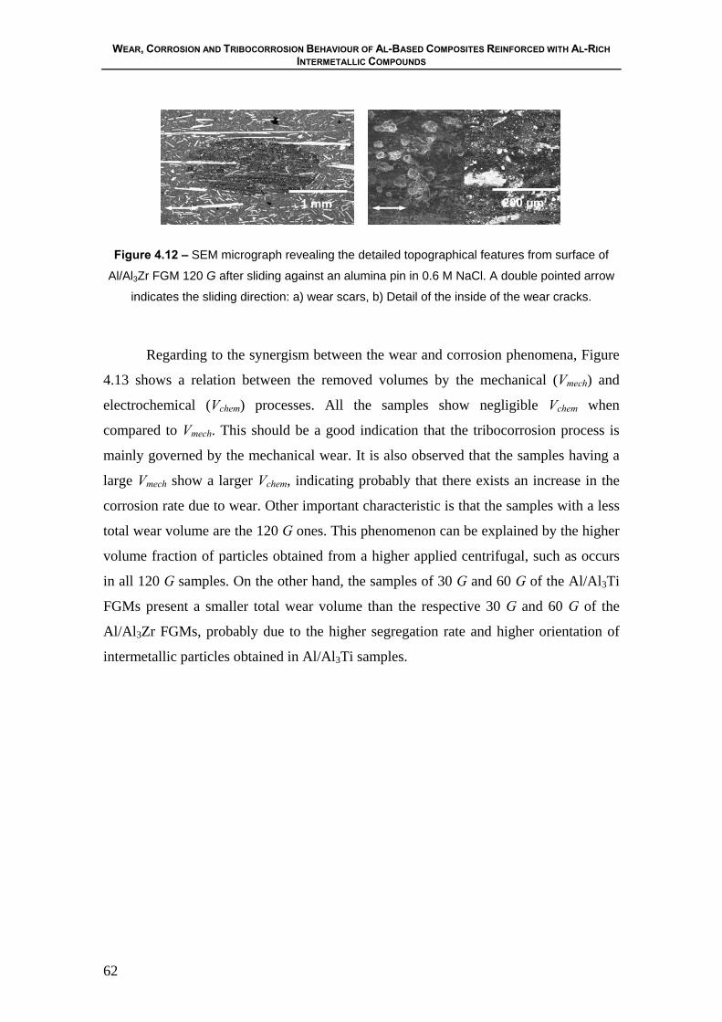
WEAR, CORROSION AND TRIBOCORROSION BEHAVIOUR OF AL-BASED COMPOSITES REINFORCED WITH AL-RICH INTERMETALLIC COMPOUNDS
62
Figure 4.12 – SEM micrograph revealing the detailed topographical features from surface of
Al/Al3Zr FGM 120 G after sliding against an alumina pin in 0.6 M NaCl. A double pointed arrow
indicates the sliding direction: a) wear scars, b) Detail of the inside of the wear cracks.
Regarding to the synergism between the wear and corrosion phenomena, Figure
4.13 shows a relation between the removed volumes by the mechanical (Vmech) and
electrochemical (Vchem) processes. All the samples show negligible Vchem when
compared to Vmech. This should be a good indication that the tribocorrosion process is
mainly governed by the mechanical wear. It is also observed that the samples having a
large Vmech show a larger Vchem, indicating probably that there exists an increase in the
corrosion rate due to wear. Other important characteristic is that the samples with a less
total wear volume are the 120 G ones. This phenomenon can be explained by the higher
volume fraction of particles obtained from a higher applied centrifugal, such as occurs
in all 120 G samples. On the other hand, the samples of 30 G and 60 G of the Al/Al3Ti
FGMs present a smaller total wear volume than the respective 30 G and 60 G of the
Al/Al3Zr FGMs, probably due to the higher segregation rate and higher orientation of
intermetallic particles obtained in Al/Al3Ti samples.
1 mm 200 µm
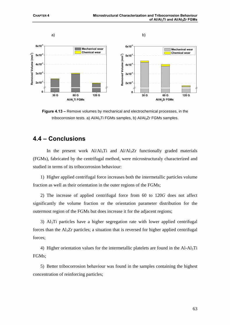
CHAPTER 4 Microstructural Characterization and Tribocorrosion Behaviour of Al/Al3Ti and Al/Al3Zr FGMs
63
a) b)
30 G 60 G 120 G0
2x10⁻²
3x10⁻²
4x10⁻²
5x10⁻²
6x10⁻²
Mechanival wear Chemical wear
Rem
oved
Vol
ume
(mm
3 )
Al/Al3Ti FGMs30 G 60 G 120 G
0
2x10⁻²
3x10⁻²
4x10⁻²
5x10⁻²
6x10⁻²
R
emov
ed V
olum
e (m
m3 )
Al/Al3Zr FGMs
Mechanival wear Chemical wear
Figure 4.13 – Remove volumes by mechanical and electrochemical processes, in the
tribocorrosion tests. a) Al/Al3Ti FGMs samples, b) Al/Al3Zr FGMs samples.
4.4 – Conclusions
In the present work Al/Al3Ti and Al/Al3Zr functionally graded materials
(FGMs), fabricated by the centrifugal method, were microstructuraly characterized and
studied in terms of its tribocorrosion behaviour:
1) Higher applied centrifugal force increases both the intermetallic particles volume
fraction as well as their orientation in the outer regions of the FGMs;
2) The increase of applied centrifugal force from 60 to 120G does not affect
significantly the volume fraction or the orientation parameter distribution for the
outermost region of the FGMs but does increase it for the adjacent regions;
3) Al3Ti particles have a higher segregation rate with lower applied centrifugal
forces than the Al3Zr particles; a situation that is reversed for higher applied centrifugal
forces;
4) Higher orientation values for the intermetallic platelets are found in the Al-Al3Ti
FGMs;
5) Better tribocorrosion behaviour was found in the samples containing the highest
concentration of reinforcing particles;
WEAR, CORROSION AND TRIBOCORROSION BEHAVIOUR OF AL-BASED COMPOSITES REINFORCED WITH AL-RICH INTERMETALLIC COMPOUNDS
64
6) The tribocorrosion processes of Al-Al3Ti and Al-Al3Zr FGMs samples are
mainly governed by mechanical wear. It was verified that exits a synergism between the
wear and the corrosion process in which this last increases with wear acts.
Acknowledgements
The authors gratefully acknowledge the financial support provided by 21st COE
Research of the Ministry of Education Culture, Sports Science and Technology of
Japan. Acknowledgments also to “FCT”, Portugal, through the project
SFRH/BPD/5518/2001.
4.5 – References
[1] M. Yamaguchi, Y. Umakoski, Intermetallic Compounds, Tokyo, Japan: Nikkan
Kogyou Shinbunsya, (1984).
[2] S.H. Wang, P.W. Kao, Acta Mater 46 (1998) 2675.
[3] S.H. Wang, P.W. Kao, C.P. Chang, Scripta Mater 40 (1999) 289.
[4] Z. Sun, H. Hashimoto, Q. Wang, Y. Park, T. Abe, Mater Trans 41 (2000) 597.
[5] Y. Fukui, JSME Inst J Series III 34 (1991) 144.
[6] Y. Fukui, Y. Watanabe, Metal Mater Trans A 27A (1996) 4145.
[7] Y. Watanabe, N. Yamanaka, Y. Fukui, Composites Part A 29A (1998) 595.
[8] Y. Watanabe, Y. Fukui, Aluminum Trans 2 (2000) 195.
[9] Y. Watanabe, N. Yamanaka, Y. Fukui, Metal Mater Trans A 30A (1999) 3253.
[10] Y. Watanabe, H. Eryu, Y. Fukui, Ceramic Trans 114 (2001) 675.
[11] H. Asanuma, M. Hirohashi, K. Miyoshi, Y. Sakamoto, K. Hayashi, Proc 3rd Int
SAMPE Met Conf (1992) M581.
[12] R.B. Pipes, R.L. McCullough, D.G. Taggart, Polymer Compo 3 (1982) 34.
[13] R.C. Wetherhold, P.D. Scott, Compo Sci Tech 62 (2002) 393.
CHAPTER 4 Microstructural Characterization and Tribocorrosion Behaviour of Al/Al3Ti and Al/Al3Zr FGMs
65
[14] L. Lajoye, M. Suery, Proc Int Symp on Advances in Cast Reinforced Metal
Composites, ASM International (1988) 15.
[15] D. Roy, B. Basu, A.B. Mallick, Intermetallics 13 (2005) 733.
[16] J.M. Wu , Z.Z. Li, Wear 244 (2000) 147.
[17] D. Landolt, S. Mischler, M. Stemp, Electrochimica Acta 46 (2001) 3913.
[18] P. Jemmely, S. Mischler, D. Landolt, Tribology International 32 (1999) 295.
[19] P. Jemmely, S. Mischler, D. Landolt, Wear 237 (2000) 63.
[20] S.H. McGee, R.L. McCullough, J. Appl. Phys. 55 (1984) 1394.
[21] L.M. Gonzalez, F.L. Cumbrera, F. Sanchez-Bajo, A. Pajares, Acta Metall.
Mater. 42 (1994) 689.

CHAPTER 5 Influence of the Reinforcing Particles Distribution on the Study of Tribocorrosion of Al/Al3Zr FGMs Produced by Centrifugal Casting
67
CHAPTER 5
Influence of the Reinforcing Particles Distribution on the Study of Tribocorrosion of Al/Al3Zr FGMs
Produced by Centrifugal Casting
Sónia C. Ferreira 1, Edith Ariza 2, Luís A. Rocha 3, Paulo D. Sequeira 4, Yoshimi Watanabe 5
1 Researcher, Materials Engineering – CIICS, Centro de Investigação em Interfaces e
Comportamento de Superfícies, Universidade do Minho, Campus de Azurém, 4800-058
Guimarães, Portugal.
2 Postdoctoral Researcher, Metallurgical Engineering – CIICS, Centro de Investigação em
Interfaces e Comportamento de Superfícies, Universidade do Minho, Campus de Azurém,
4800-058 Guimarães, Portugal.
3 Associate Professor - CIICS, Centro de Investigação em Interfaces e Comportamento de
Superfícies, Universidade do Minho, Campus de Azurém, 4800-058 Guimarães, Portugal.
4 Researcher, Materials Engineering – Department of Engineering Physics, Electronics and
Mechanics, Graduate School of Engineering, Nagoya Institute of Technology, Gokiso-cho,
Showa-ku, Nagoya 466-8555, Japan. CIICS – Centro de Investigação em Interfaces e
Comportamento de Superfícies, Universidade do Minho, Campus de Azurém, 4800-058
Guimarães, Portugal.
5 Associate Professor, Department of Engineering Physics, Electronics and Mechanics,
Graduate School of Engineering, Nagoya Institute of Technology, Gokiso-cho, Showa-ku,
Nagoya 466-8555, Japan

WEAR, CORROSION AND TRIBOCORROSION BEHAVIOUR OF AL-BASED COMPOSITES REINFORCED WITH AL-RICH INTERMETALLIC COMPOUNDS
68
Abstract
Zirconium trialuminide (Al3Zr) possess low density, high hardness, good
oxidation resistance, thermal stability and high melting temperature. However, their
application is limited because they are brittle at low temperatures. However, these
intermetallics have shown sufficient promising characteristics to reinforce aluminium
alloys for advanced applications. Some works have been carried out on Al/Al3Zr FGMs
concerning their microstructural characteristics and wear behaviour. Nevertheless,
tribocorrosion studies had still not been carried out. In this work, the corrosion-wear of
Al/Al3Zr immersed in 0.6 M NaCl solution and sliding against an alumina pin is
analyzed. These materials were produced by centrifugal casting from an Al-5 mass % Zr
alloy with centrifugal forces applied to the mould of 30, 60 and 120 G (units of gravity).
Before tribocorrosion tests, the corrosion behaviour was evaluated by potentiodynamic
polarization. The tribocorrosion tests were performed in the pin-on-plate configuration.
The tests were made in the perpendicular direction to the centrifugal force in two areas
with different gradient of distribution of Al3Zr. After the tests, the samples were
analyzed by SEM to identify the phenomena of corrosion and wear in the surfaces.
Keywords: Corrosion, Tribocorrosion, Al/Al3Zr FGMs
5.1 – Introduction
Aluminium-intermetallic compounds fabricated by centrifugal casting have been
extensively studied due to the promising properties of the material, simple fabrication
technology, easiness to control technology parameters and small investment [1,2]. The
Al/Al3Zr functional graded material (FGM) fabricated by centrifugal casting, present a
gradient distribution of intermetallic compounds [3] that may result in better properties
than homogenous materials. This method, which was proposed by Fukui et al. [4],
consists on the application of a centrifugal force to a suspension of dispersed material,
such as ceramics or intermetallic particles, in the molten metal. Acting on the
centrifugal casting parameters the formation of the desired gradation is obtained. In fact,
CHAPTER 5 Influence of the Reinforcing Particles Distribution on the Study of Tribocorrosion of Al/Al3Zr FGMs Produced by Centrifugal Casting
69
the composition gradient is achieved primarily by the difference in density between the
molten metal and particles.
Tribocorrosion is an irreversible transformation of a material resulting from
simultaneous physico-chemical and mechanical surface interactions occurring in a
tribological contact. In general, tribocorrosion leads to the degradation of the materials
and conduces to the weakening of the performance of a contact [7-11].
The study of the tribocorrosion behaviour of Al/Al3Zr FGMs is important
because these composites are intended to be used for aircraft and automotive
applications [5-6]. In practice, most of these components will be under corrosion-wear
interaction, which might cause material to be removed from sliding surfaces exposed to
corrosion environments, such as organics fluids or aqueous lubricants [7]. In a
tribocorrosion system, the chemical and mechanical degradation mechanisms are not
independent of each other and synergistic effects can result in accelerated material
removal [8]. In this paper, corrosion and tribocorrosion behaviour of Al/Al3Zr FGMs
were studied in two regions with different gradients of intermetallic compounds.
5.2 – Experimental Methods
The Al/Al3Zr FGMs were produced by the centrifugal method, from Al-5 mass
% Zr commercial alloy, as described by Sequeira et al. [3]. In the centrifugal method the
master-alloy ingot is heated up to a temperature located between its solidus and liquidus
temperatures, where most of the intermetallic platelets remain solid in the liquid matrix.
It is then poured into a rotating mould in order to obtain ring-shaped samples which
have an outer diameter of 90 mm, 25 mm in height and a length of 20-25 mm (see
Figure 5.1). The temperature of the melting furnace was 1173 K and the applied
centrifugal casting forces were 30, 60 and 120 G (units of gravity).

WEAR, CORROSION AND TRIBOCORROSION BEHAVIOUR OF AL-BASED COMPOSITES REINFORCED WITH AL-RICH INTERMETALLIC COMPOUNDS
70
Figure 5.1 – Schematic of the FGM ring showing the studied plane, perpendicular to the
rotation direction.
Samples surfaces were polished using SiC papers and diamond paste up to 1 μm.
Before corrosion and tribocorrosion tests, the samples were ultrasonically cleaned in
ethanol for 15 minutes and then in distilled water for 10 minutes and finally dried.
The corrosion behaviour was evaluated by potentiodynamic polarization tests at
room temperature in a 0.6 M NaCl solution. The electrochemical cell consisted in a
standard three electrode arrangement. The auxiliary electrode was a platinum sheet with
an area of 1 cm2 and a saturated calomel electrode (SCE) was used as reference. The
area of the working electrode was set in 0.2 cm2. A PGP201 Potentiostat/Galvanostat
(Radiometer Denmark), controlled by the VoltaMaster-1 software, was used to carry out
the polarization measurements. Prior to polarization tests, the open circuit potential
(OCP) was monitored during 3600 s, after which the samples were anodically polarized
from -1500 to 200 mV at a scan rate of 2 mV s-1.
The tribocorrosion tests were performed using a reciprocating tribometer (Plint
TE67/R). An alumina pin (truncated cone geometry and with a tip of 0.8 mm in
diameter) was used as counterbody and mounted vertically on the samples immersed in
the electrolyte (exposed area = 0.95 cm2). The samples were used as plates positioned
horizontally and mounted in an acrylic electrochemical cell (20 ml of 0.6 M NaCl
solution was used as electrolyte) (see Figure 5.2). All potentials were measured and
expressed with reference to a standard calomel electrode (SCE), and a platinum wire
with an area of 1 cm2 served as auxiliary electrode. A Voltalab PGZ100 Potentiostat
Rotating axis
Outer region G Inner region
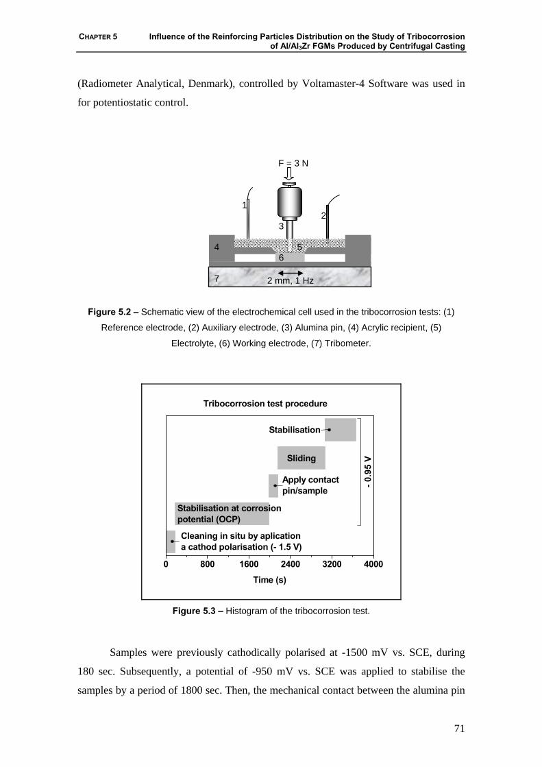
CHAPTER 5 Influence of the Reinforcing Particles Distribution on the Study of Tribocorrosion of Al/Al3Zr FGMs Produced by Centrifugal Casting
71
(Radiometer Analytical, Denmark), controlled by Voltamaster-4 Software was used in
for potentiostatic control.
Figure 5.2 – Schematic view of the electrochemical cell used in the tribocorrosion tests: (1)
Reference electrode, (2) Auxiliary electrode, (3) Alumina pin, (4) Acrylic recipient, (5)
Electrolyte, (6) Working electrode, (7) Tribometer.
0 800 1600 2400 3200 4000
Stabilisation
Time (s)
Tribocorrosion test procedure
Cleaning in situ by aplicationa cathod polarisation (- 1.5 V)
- 0.9
5 V
Stabilisation at corrosionpotential (OCP)
Apply contactpin/sample
Sliding
Figure 5.3 – Histogram of the tribocorrosion test.
Samples were previously cathodically polarised at -1500 mV vs. SCE, during
180 sec. Subsequently, a potential of -950 mV vs. SCE was applied to stabilise the
samples by a period of 1800 sec. Then, the mechanical contact between the alumina pin
2 mm, 1 Hz
F = 3 N
1 2
3 4 5 6 7

WEAR, CORROSION AND TRIBOCORROSION BEHAVIOUR OF AL-BASED COMPOSITES REINFORCED WITH AL-RICH INTERMETALLIC COMPOUNDS
72
and the sample plate was applied and after 180 sec the sliding began. The reciprocating
wear test was performed with a normal load of 3 N, displacement amplitude of 2 mm
and a frequency of 1 Hz. The sliding time was 900 s. A histogram of tribocorrosion test
is present in figure 5.3. When sliding was stopped, the pin and the sample were
removed from the solution and cleaned ultrasonically in ethanol. The total wear volume
(Vtot = Vmech + Vchem) [7,11], caused by the contribution of wear and corrosion, was
determined by a profilometer method, using a Perthometer S5P roughness meter, by
calculating the average of the cross-sectional area multiplied by the stroke length. The
chemical wear volume (Vchem) was determined from the measured current, using
Faraday’s law, Vchem = (Q⋅M) / (n⋅F⋅ρ); where, Q is the electric charge, which is
obtained by integrating the current density curve with the time, along of the sliding
time, M is the atomic mass of the aluminium (27 g.mol-1), n the valence of dissolution
of the aluminium (+3), F the Faraday’s constant (9.649⋅10-4 C mol-1) and ρ is the
density of the aluminium(2.7⋅10-3 g.mm-3). The mechanical wear volume, Vmech which is
the volume of material mechanically removed was obtained by subtracting Vtot − Vchem
[7,8,11].
5.3 – Results and Discussion
5.3.1 – Corrosion Behaviour
After being immersed in the 0.6 M NaCl solution, the corrosion potential (Ecorr)
of the samples was monitored during 60 min. The obtained curves, smoothed because of
its high fluctuation, are presented in Figure 5.4 a.1), b.1) and c.1). As it can be
observed, all samples, except the 120 G inner, reveal an increase in the corrosion
potential with the time, indicating the formation of a passive film.
The Al/Al3Zr FGMs 30 G and 60 G samples show a similar behaviour, in terms
of thermodynamic stability (Ecorr between -1100 and -800 mV). The sample obtained
with 30 G reveals a little better behaviour. Conversely, the Al/Al3Zr FGMs 120 G inner
sample presents a different behaviour. The more active corrosion potential exhibited by
this last sample reflects less thermodynamic stability and therefore its higher corrosion
tendency.
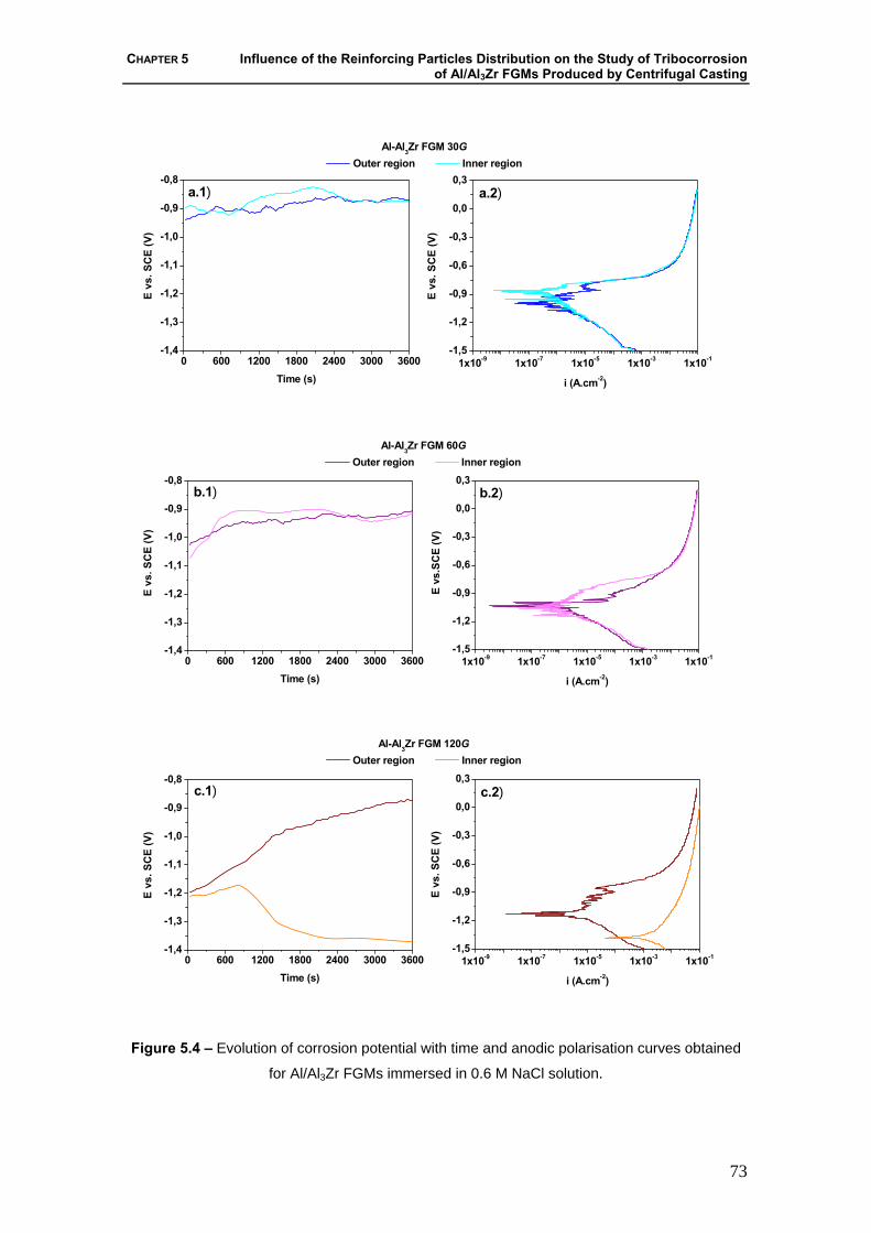
CHAPTER 5 Influence of the Reinforcing Particles Distribution on the Study of Tribocorrosion of Al/Al3Zr FGMs Produced by Centrifugal Casting
73
0 600 1200 1800 2400 3000 3600-1,4
-1,3
-1,2
-1,1
-1,0
-0,9
-0,8
1x10⁻⁹ 1x10⁻⁷ 1x10⁻⁵ 1x10⁻³ 1x10⁻¹-1,5
-1,2
-0,9
-0,6
-0,3
0,0
0,3a.2)
E vs
. SC
E (V
)
i (A.cm-2)
Al-Al3Zr FGM 30G Outer region Inner region
E vs
. SC
E (V
)
Time (s)
a.1)
0 600 1200 1800 2400 3000 3600-1,4
-1,3
-1,2
-1,1
-1,0
-0,9
-0,8
1x10⁻⁹ 1x10⁻⁷ 1x10⁻⁵ 1x10⁻³ 1x10⁻¹-1,5
-1,2
-0,9
-0,6
-0,3
0,0
0,3b.2)
E vs
.SC
E (V
)
i (A.cm-2)
Al-Al3Zr FGM 60G Outer region Inner region
E vs
. SC
E (V
)
Time (s)
b.1)
0 600 1200 1800 2400 3000 3600-1,4
-1,3
-1,2
-1,1
-1,0
-0,9
-0,8
1x10⁻⁹ 1x10⁻⁷ 1x10⁻⁵ 1x10⁻³ 1x10⁻¹-1,5
-1,2
-0,9
-0,6
-0,3
0,0
0,3c.2)
E vs
. SC
E (V
)
i (A.cm-2)
Al-Al3Zr FGM 120G Outer region Inner region
E vs
. SC
E (V
)
Time (s)
c.1)
Figure 5.4 – Evolution of corrosion potential with time and anodic polarisation curves obtained
for Al/Al3Zr FGMs immersed in 0.6 M NaCl solution.

WEAR, CORROSION AND TRIBOCORROSION BEHAVIOUR OF AL-BASED COMPOSITES REINFORCED WITH AL-RICH INTERMETALLIC COMPOUNDS
74
Figure 5.4 a.2), b.2) and c.2) presents the anodic polarisation curves obtained for
all samples. As it can be observed the corrosion behaviour of Al/Al3Zr FGMs samples is
similar, except for the sample 120 G inner. In this case, in according to the open circuit
potential results, reveals the worst corrosion behaviour. As it can be seen, the
determination of the corrosion current density (icorr) for all samples presents some
difficulties because of the lot of noise and instability of the samples immersed in the
electrolyte.
5.3.2 – Tribocorrosion Behaviour
Results of tribocorrosion tests obtained in Al/Al3Zr FGMs samples are presented
in Figure 5.5. As it can be seen all samples show a similar evolution of the current with
the time. The drastic increase in the current at 180 seconds is due to the change of the
applied potential from -1500 mV (to clean the sample) to -950mV to stabilize the same.
The evolution of the current density and the friction coefficient (μ) with the time in the
sliding period is also presented. As it can be seen, all samples show an increase in the
current density at the beginning of sliding, corresponding to the initial contact between
the counterbody and the surface of the sample. After this, the current density of all
samples decreases attempting to reach a steady state. An exception occurs with 60 G
and 120 G outer samples. In these last samples besides the little decrease of current
density after the initial contact with the counterbody, the current values are higher when
compared with the other samples. It is also possible to note that at the end of sliding
period, the current density of all samples decrease reaching values similar to those
observed before sliding. This behaviour shows a clear negative influence of the sliding
processes on the deterioration of surface samples. In terms of friction coefficient (μ) all
samples show a similar behaviour, i. e. increases until achieving a steady state. Once
again and similarly as the current density evolution, an exception occurs with the 60 G
outer and 120 G outer samples. The μ of these last samples monotonically increase with
the sliding time.
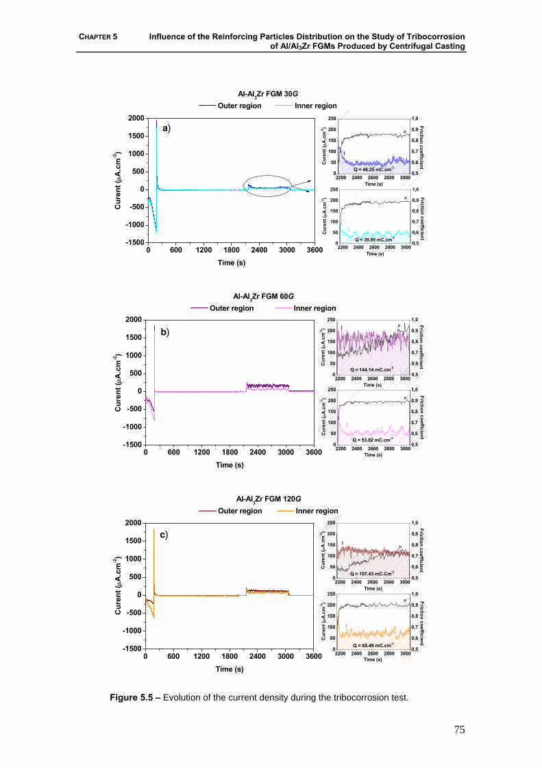
CHAPTER 5 Influence of the Reinforcing Particles Distribution on the Study of Tribocorrosion of Al/Al3Zr FGMs Produced by Centrifugal Casting
75
0 600 1200 1800 2400 3000 3600-1500
-1000
-500
0
500
1000
1500
2000
0,5
0,6
0,7
0,8
0,9
1,0
2200 2400 2600 2800 30000
50
100
150
200
250
Friction coefficient
Time (s)
Cur
ent (
μA.c
m-2)
Q = 39.89 mC.cm-2
μ
I
0,5
0,6
0,7
0,8
0,9
1,0
2200 2400 2600 2800 30000
50
100
150
200
250Friction coefficientC
uren
t (μA
.cm
-2)
Time (s)
Q = 48.25 mC.cm-2
I
I
μ
C
uren
t (μA
.cm
-2)
Time (s)
Al-Al3Zr FGM 30G Outer region Inner region
a)
0 600 1200 1800 2400 3000 3600-1500
-1000
-500
0
500
1000
1500
2000
0,5
0,6
0,7
0,8
0,9
1,0
2200 2400 2600 2800 30000
50
100
150
200
250
Friction coefficient
Time (s)
Cur
ent (
μA.c
m-2)
μ
I
Q = 53.82 mC.cm-2
0,5
0,6
0,7
0,8
0,9
1,0
2200 2400 2600 2800 30000
50
100
150
200
250
Friction coefficient
Time (s)
Cur
ent (
μA.c
m-2)
μI
Q = 144.14 mC.cm-2
b)
Cur
ent (
μA.c
m-2)
Al-Al3Zr FGM 60G Outer region Inner region
Time (s)
0 600 1200 1800 2400 3000 3600-1500
-1000
-500
0
500
1000
1500
2000
0,5
0,6
0,7
0,8
0,9
1,0
2200 2400 2600 2800 30000
50
100
150
200
250μ
Q = 65.49 mC.cm-2
Friction coefficient
Time (s)
Cur
ent (
μA.c
m-2)
I
0,5
0,6
0,7
0,8
0,9
1,0
2200 2400 2600 2800 30000
50
100
150
200
250
Friction coefficient
Time (s)
Cur
ent (
μA.c
m-2)
Iμ
Q = 107.43 mC.Cm-2
Cur
ent (
μA.c
m-2)
Al-Al3Zr FGM 120G Outer region Inner region
Time (s)
c)
Figure 5.5 – Evolution of the current density during the tribocorrosion test.

WEAR, CORROSION AND TRIBOCORROSION BEHAVIOUR OF AL-BASED COMPOSITES REINFORCED WITH AL-RICH INTERMETALLIC COMPOUNDS
76
The friction coefficient was calculated as an average of the values obtained
during sliding period, eliminating the initial sliding values, i.e, excluding the running-in
period (2160-2400 s). As it can be observed in Figure 5.6, the values of the μ for 30 G
outer, 30 G inner, 60 G inner and 120G inner are near to 0.9. In the 60 G outer and 120
G outer samples, the μ increases along the sliding time, not reaching a steady state,
being for this reason impossible to calculate μ average.
Regarding the synergism between the wear and corrosion phenomena, Figure 5.6
shows a relation between the removed volumes by the mechanical (Vmech) and
electrochemical (Vchem) processes. As it can be seen, all the samples show negligible
Vchem in front to large Vmech. This should be a good indication that the tribocorrosion
process is mainly governed by the mechanical wear. Other important observation is that
samples exhibiting highest electrochemical removed volume are the 60 G outer and 120
G outer. Additionally, the sample with the highest mechanically removed volume is the
60 G outer.
0,70
0,75
0,80
0,85
0,90
0,95
1,00
0,0
2,0x10⁻²
4,0x10⁻²
6,0x10⁻²
8,0x10⁻²
1,0x10⁻¹
1,2x10⁻¹
1,4x10⁻¹
1,6x10⁻¹
Rem
oved
vol
ume
(mm
3 )
FGMs
Mechanical wear Electrochemical wear
Out In Out In Out In
30G 60G 120G
μaverage(2400-3050s)
Friction coeficient
Figure 5.6 – Removed volume by mechanical and electrochemical processes and average
friction coefficient in tribocorrosion test.
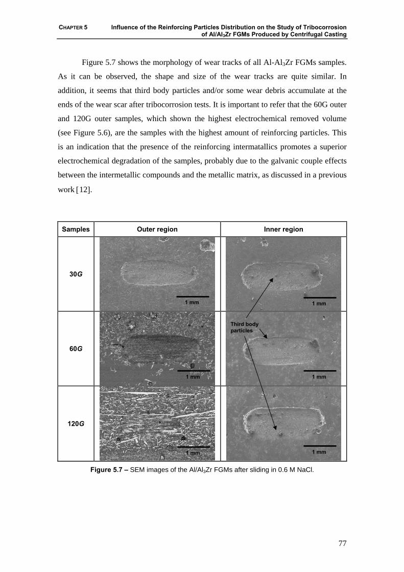
CHAPTER 5 Influence of the Reinforcing Particles Distribution on the Study of Tribocorrosion of Al/Al3Zr FGMs Produced by Centrifugal Casting
77
Figure 5.7 shows the morphology of wear tracks of all Al-Al3Zr FGMs samples.
As it can be observed, the shape and size of the wear tracks are quite similar. In
addition, it seems that third body particles and/or some wear debris accumulate at the
ends of the wear scar after tribocorrosion tests. It is important to refer that the 60G outer
and 120G outer samples, which shown the highest electrochemical removed volume
(see Figure 5.6), are the samples with the highest amount of reinforcing particles. This
is an indication that the presence of the reinforcing intermatallics promotes a superior
electrochemical degradation of the samples, probably due to the galvanic couple effects
between the intermetallic compounds and the metallic matrix, as discussed in a previous
work [12].
Samples Outer region Inner region
30G
60G
120G
Figure 5.7 – SEM images of the Al/Al3Zr FGMs after sliding in 0.6 M NaCl.
1 mm
1 mm
1 mm
1 mm
1 mm
1 mm
Third body particles
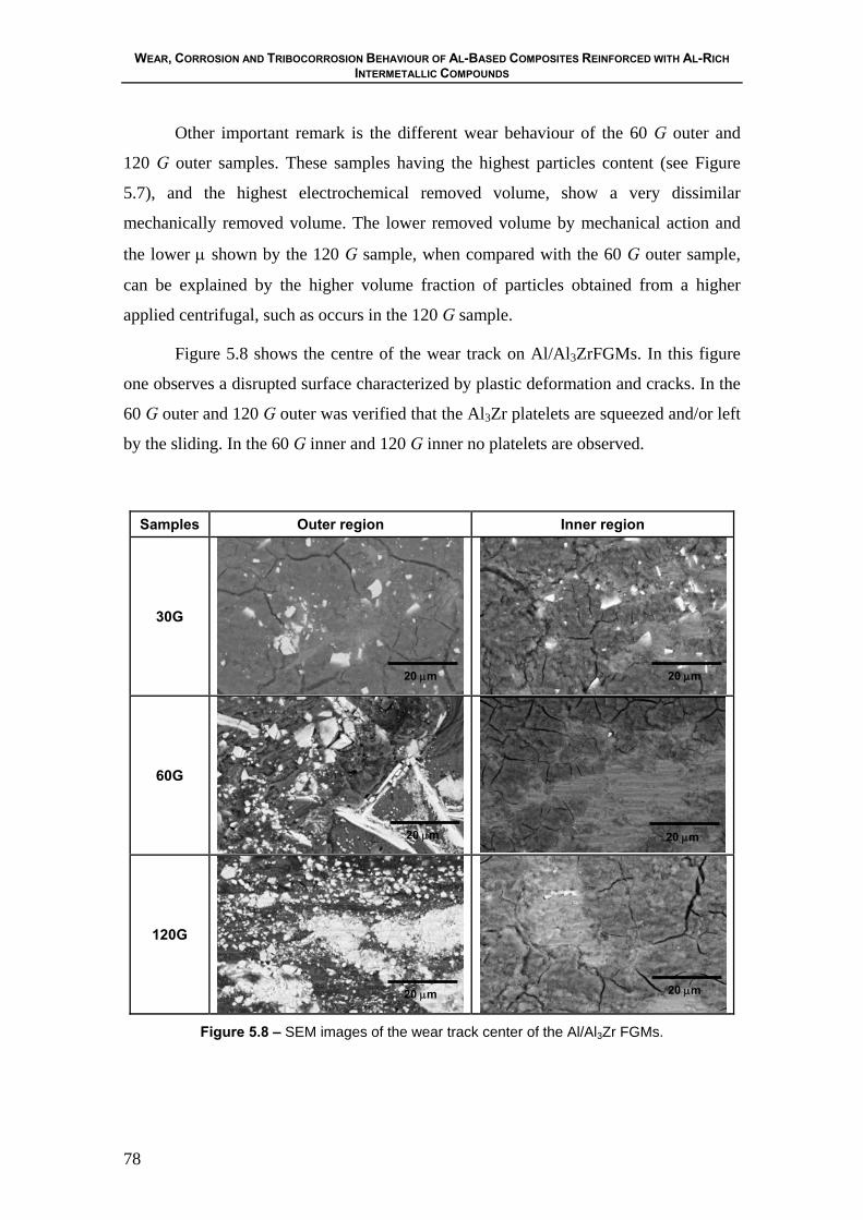
WEAR, CORROSION AND TRIBOCORROSION BEHAVIOUR OF AL-BASED COMPOSITES REINFORCED WITH AL-RICH INTERMETALLIC COMPOUNDS
78
Other important remark is the different wear behaviour of the 60 G outer and
120 G outer samples. These samples having the highest particles content (see Figure
5.7), and the highest electrochemical removed volume, show a very dissimilar
mechanically removed volume. The lower removed volume by mechanical action and
the lower μ shown by the 120 G sample, when compared with the 60 G outer sample,
can be explained by the higher volume fraction of particles obtained from a higher
applied centrifugal, such as occurs in the 120 G sample.
Figure 5.8 shows the centre of the wear track on Al/Al3ZrFGMs. In this figure
one observes a disrupted surface characterized by plastic deformation and cracks. In the
60 G outer and 120 G outer was verified that the Al3Zr platelets are squeezed and/or left
by the sliding. In the 60 G inner and 120 G inner no platelets are observed.
Samples Outer region Inner region
30G
60G
120G
Figure 5.8 – SEM images of the wear track center of the Al/Al3Zr FGMs.
20 μm
20 μm
20 μm
20 μm 20 μm
20 μm

CHAPTER 5 Influence of the Reinforcing Particles Distribution on the Study of Tribocorrosion of Al/Al3Zr FGMs Produced by Centrifugal Casting
79
5.4 – Conclusions
In the present study, the tribocorrosion behaviour of Al/Al3Zr FGMs, was
investigated in a 0.6 M NaCl solution:
1) The electrochemical behaviour of samples showed that some galvanic effects
between the intermetallic particles and the metal matrix might affect the overall
corrosion process.
2) The tribocorrosion degradation of Al/Al3Zr FGMs is mainly governed by the
mechanical wear.
3) The better tribocorrosion behaviour, i.e., the lowest removal volumes by both
mechanical and chemical action, was observed in the samples containing the smaller
concentration of reinforcing particles.
Acknowledgements
The authors gratefully acknowledge the financial support provided by 21st COE
Research of the Ministry of Education Culture, Sports Science and Technology of
Japan. Acknowledgments are also presented to “FCT”, Portugal, through project
SFRH/BPD/5518/2001.
5.5 – References
[1] Y. Watanabe, Y. Fukui, Rec. Res. Devel. Metall. Mater. Sci. 4 (2000) 51.
[2] Y. Watanabe, Y. Fukui, Aluminum Trans. 2 (2000) 195.
[3] P.D. Sequeira, Y. Watanabe, L.A. Rocha, Mater. Sci. Forum 492 (2005) 609.
[4] Y. Fukui, JSME Int. J. Series III 34 (1991) 144.
[5] D. Roy, B. Basu, A.B. Mallick, Intermetallics 13 (2005) 733.
[6] J.R. Gomes, A.S. Miranda, L.A. Rocha, S.J. Crnkovic, V. Silva, R.F. Silva, Int.
J. Appl. Mech. Eng. 7 (2002) 791.
[7] S. Mischler, A. Spiegel, M. Stemp, D. Landolt, Wear 251 (2001) 1295.
WEAR, CORROSION AND TRIBOCORROSION BEHAVIOUR OF AL-BASED COMPOSITES REINFORCED WITH AL-RICH INTERMETALLIC COMPOUNDS
80
[8] S. Mischler, A. Spiegel, D. Landolt, Wear 225-229 (1999) 1078.
[9] P. Jemmely, S. Mischler, D. Landolt, Tribology International 32 (1999) 295.
[10] P. Jemmely, S. Mischler, D. Landolt, Wear 237(2000) 63.
[11] D. Landolt, S. Mischler, M. Stemp, Electrochim. Acta 46 (2001) 3913.
[12] S.C. Ferreira, L.A. Rocha, E. Ariza, J.R. Gomes, P.D. Sequeira, Y. Watanabe,
Tribocorrosion Behaviour of Al-Al3Ti and Al-Al3Zr FGMs, European Corrosion
Conference (EUROCORR 2005), Lisbon, Portugal, September, 2005.
CHAPTER 6 Microstructural Characterization and Wear Behaviour of Two-Phase Al-5 mass % Ti Alloy Deformed By Equal-Channel Angular Pressing
81
CHAPTER 6
Microstructural Characterization and Wear Behaviour of Two-Phase Al-5 mass % Ti Alloy Deformed By Equal-Channel Angular Pressing
P.D. Sequeira a, S.C. Ferreira a, Y. Watanabe b, L.A. Rocha a,c,J.R. Gomes a,c
a Research Centre on Interfaces and Surface Performance, University of Minho, Campus de
Azurém, 4800-058 Guimarães, Portugal
b Department of Engineering Physics, Electronics and Mechanics, Graduate School of
Engineering, Nagoya Institute of Technology, Gokiso-Chu, Showa-Ku, 466-8555 Nagoya, Japan
c Department of Mechanical Engineering, University of Minho, Campus de Azurém, 4800-058
Guimarães, Portugal
Abstract
Equal-channel angular pressing (ECAP) was used to induce large plastic strains
in an Al/Al3Ti composite (Al-5 mass % Ti alloy). Microstructural changes and
mechanical properties were studied for the as-cast alloy and for samples pressed from 1
up to 6 passes through the die. Due to the high strain imposed in the ECAP process
Al3Ti particles break-up occurs and they become aligned in bands in the deformation
direction. Hardness increases with an increase in the number of passes through the die.
The wear resistance is lower in the deformed samples than in the as-cast composite.
Al3Ti particle alignment in bands along the deformation direction leads to anisotropy in

WEAR, CORROSION AND TRIBOCORROSION BEHAVIOUR OF AL-BASED COMPOSITES REINFORCED WITH AL-RICH INTERMETALLIC COMPOUNDS
82
the wear behaviour, with higher wear resistance found in the direction parallel to the
deformation direction.
Keywords: Equal-Channel Angular Pressing (ECAP); Titanium Aluminides; Wear
6.1 – Introduction
Al-rich intermetallic compounds as reinforcing dispersoids in Al alloys are of
significant interest as they affect mechanical properties, corrosion resistance, surface
finish and electrical resistivity of Al alloys. Moreover, intermetallic compounds such as
Al3Ti are thermally stable making Al alloys reinforced by Al3Ti dispersoids attractive
for elevated temperature applications [1].
A high interest exists in using ECAP for processing of ultrafine-grained (UFG)
microstructures. With this method, by multiple passes through a die, very high strains
can be achieved without any change in the billet dimensions. The resulting UFG
metallic materials exhibit high strength while maintaining toughness and ductility [2-5].
Most of the previous studies have been performed mainly in single-phase
alloys, although research into processing of two-phase Al alloys by ECAP has recently
been gaining more attention. Shin et al. [6-8] have reported on the strengthening effect
of ECAP on low-carbon steels. Microstructure of two-phase Al-1.7 at % Cu alloy
deformed by ECAP was studied by Murayama et al. [9]. Stolyarov et al. [10] study on
the processing of Al-5 wt % Fe alloy by ECAP revealed enhanced Fe solubility in the
Al alloy and also improvement in strength, ductility and microhardness. Also Al metal
matrix composites reinforced by silicon carbide (SiC) whiskers [11] or by aluminium
oxide (Al2O3) particles [12] have been the object of recent research.
Due to potential tribological application in the automotive and aerospace
industries, wear behaviour of Al alloys reinforced by Al3Ti dispersoids has been studied
previously. Cold deformation of Al-10 wt % Ti alloy was shown to decrease the wear
resistance at the adhesive wear regime but to improve it, to a certain degree, at the
oxidation stage [13]. In another study it was indicated that the dry sliding wear
resistance of the Al alloys reinforced by Al3Ti dispersoids increases with increasing
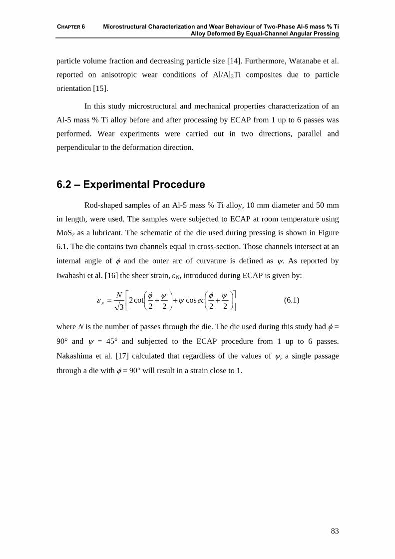
CHAPTER 6 Microstructural Characterization and Wear Behaviour of Two-Phase Al-5 mass % Ti Alloy Deformed By Equal-Channel Angular Pressing
83
particle volume fraction and decreasing particle size [14]. Furthermore, Watanabe et al.
reported on anisotropic wear conditions of Al/Al3Ti composites due to particle
orientation [15].
In this study microstructural and mechanical properties characterization of an
Al-5 mass % Ti alloy before and after processing by ECAP from 1 up to 6 passes was
performed. Wear experiments were carried out in two directions, parallel and
perpendicular to the deformation direction.
6.2 – Experimental Procedure
Rod-shaped samples of an Al-5 mass % Ti alloy, 10 mm diameter and 50 mm
in length, were used. The samples were subjected to ECAP at room temperature using
MoS2 as a lubricant. The schematic of the die used during pressing is shown in Figure
6.1. The die contains two channels equal in cross-section. Those channels intersect at an
internal angle of φ and the outer arc of curvature is defined as ψ. As reported by
Iwahashi et al. [16] the sheer strain, εN, introduced during ECAP is given by:
⎥⎦
⎤⎢⎣
⎡⎟⎠⎞
⎜⎝⎛ ++⎟
⎠⎞
⎜⎝⎛ +=
22cos
22cot2
3ψφψψφε ecN
N (6.1)
where N is the number of passes through the die. The die used during this study had φ =
90° and ψ = 45° and subjected to the ECAP procedure from 1 up to 6 passes.
Nakashima et al. [17] calculated that regardless of the values of ψ, a single passage
through a die with φ = 90° will result in a strain close to 1.

WEAR, CORROSION AND TRIBOCORROSION BEHAVIOUR OF AL-BASED COMPOSITES REINFORCED WITH AL-RICH INTERMETALLIC COMPOUNDS
84
Φ = 90°
Ψ = 45°
Die
Pressure
Plunger
Sample
0
zy
x
Deformation Direction
Plane X-Z
Figure 6.1 – Schematic representation of the ECAP die.
6.2.1 – Microstructural Analysis
Samples were cut along the longitudinal plane (plane x-z in Figure 6.1) and
characterized by optical microscopy (OM) and scanning electron microscopy (SEM).
Computer analysis was performed and size and volume fraction of Al3Ti particles
measured.
6.2.2 – Mechanical Properties The wear tests were carried out in a Plint TE67 tribometer in the ball-on-plate
test geometry with reciprocating motion of the plate. The ECAP samples were used as
plate and AISI 52100 steel as ball, with 0.4 mm diameter. Sliding was performed in the
absence of lubrication at ambient temperature, under controlled conditions of humidity
in the surrounding atmosphere, with relative humidity of 50 % ± 5 % and with the
absence of lubrication. The normal applied load was fixed at 3 N. The total sliding
distance was 10 m, displacement was 6 mm and the frequency of the oscillation motion
was 1 Hz. The wear coefficient, K, was quantified by equation:
xWVK⋅
= (6.2)
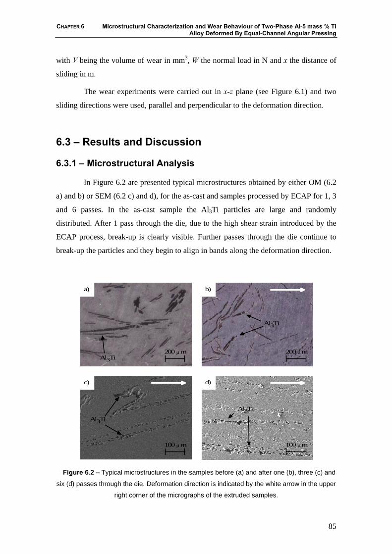
CHAPTER 6 Microstructural Characterization and Wear Behaviour of Two-Phase Al-5 mass % Ti Alloy Deformed By Equal-Channel Angular Pressing
85
with V being the volume of wear in mm3, W the normal load in N and x the distance of
sliding in m.
The wear experiments were carried out in x-z plane (see Figure 6.1) and two
sliding directions were used, parallel and perpendicular to the deformation direction.
6.3 – Results and Discussion
6.3.1 – Microstructural Analysis
In Figure 6.2 are presented typical microstructures obtained by either OM (6.2
a) and b) or SEM (6.2 c) and d), for the as-cast and samples processed by ECAP for 1, 3
and 6 passes. In the as-cast sample the Al3Ti particles are large and randomly
distributed. After 1 pass through the die, due to the high shear strain introduced by the
ECAP process, break-up is clearly visible. Further passes through the die continue to
break-up the particles and they begin to align in bands along the deformation direction.
200 μmAl3Ti
a)
200 μm
Al3Ti
100 μm
Al3Ti
c)
100 μm
d)
Al3Ti
b)
Figure 6.2 – Typical microstructures in the samples before (a) and after one (b), three (c) and
six (d) passes through the die. Deformation direction is indicated by the white arrow in the upper
right corner of the micrographs of the extruded samples.
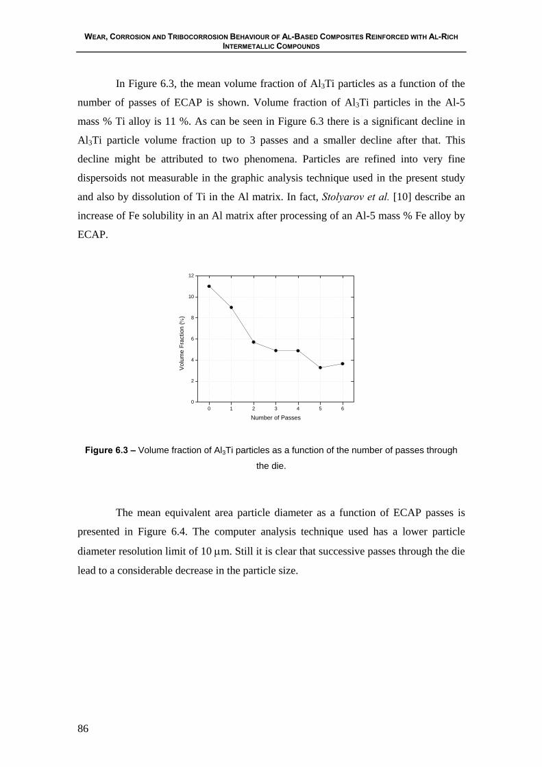
WEAR, CORROSION AND TRIBOCORROSION BEHAVIOUR OF AL-BASED COMPOSITES REINFORCED WITH AL-RICH INTERMETALLIC COMPOUNDS
86
In Figure 6.3, the mean volume fraction of Al3Ti particles as a function of the
number of passes of ECAP is shown. Volume fraction of Al3Ti particles in the Al-5
mass % Ti alloy is 11 %. As can be seen in Figure 6.3 there is a significant decline in
Al3Ti particle volume fraction up to 3 passes and a smaller decline after that. This
decline might be attributed to two phenomena. Particles are refined into very fine
dispersoids not measurable in the graphic analysis technique used in the present study
and also by dissolution of Ti in the Al matrix. In fact, Stolyarov et al. [10] describe an
increase of Fe solubility in an Al matrix after processing of an Al-5 mass % Fe alloy by
ECAP.
0 1 2 3 4 5 60
2
4
6
8
10
12
Volu
me
Frac
tion
(%)
Number of Passes
Figure 6.3 – Volume fraction of Al3Ti particles as a function of the number of passes through
the die.
The mean equivalent area particle diameter as a function of ECAP passes is
presented in Figure 6.4. The computer analysis technique used has a lower particle
diameter resolution limit of 10 μm. Still it is clear that successive passes through the die
lead to a considerable decrease in the particle size.

CHAPTER 6 Microstructural Characterization and Wear Behaviour of Two-Phase Al-5 mass % Ti Alloy Deformed By Equal-Channel Angular Pressing
87
0 1 2 3 4 5 610
15
20
25
30
35
40
45
Dia
met
er (μ
m)
Number of Passes
Figure 6.4 – Mean equal area diameter of Al3Ti particles as a function of the number of passes
through the die.
6.3.2 – Mechanical Properties
Figure 6.5 shows the effect of the number of ECAP passes on the hardness of
the Al-5 mass % Ti alloy. An increase of the hardness from the as-cast sample up to 6
ECAP passes occurs. Refining of both the Al matrix grains and the intermetallic phase
leads to this increase in the materials hardness. However, this increase is more
pronounced during the first extrusion pass becoming then almost linear from 1 to 6
passes. This trend was also observed in other studies [7,10,18].
0 1 2 3 4 5 625
30
35
40
45
50
55
60
65
70
Har
dnes
s V
icke
rs (H
V15)
Number of Passes
Figure 6.5 – Vickers Hardness as a function of the number of passes through the die.

WEAR, CORROSION AND TRIBOCORROSION BEHAVIOUR OF AL-BASED COMPOSITES REINFORCED WITH AL-RICH INTERMETALLIC COMPOUNDS
88
The influence of the number of passes of the Al-5 mass % Ti alloy on the wear
behaviour against AISI 52100 steel is shown in Figure 6.6.
0 1 2 3 4 5 60.5
1.0
1.5
2.0
2.5
3.0
K (1
0-2m
m3 N
-1m
-1)
Number of Passes
K (perpendicular sliding to the deformation direction) K (parallel sliding to the deformation direction)
Figure 6.6 – Influence of the number of ECAP passes on the wear behaviour of an Al-5 mass %
Ti against AISI 52100 steel.
A notable increase of the wear rate from the as-cast sample to the sample
deformed after 1 pass is evident in both the sliding perpendicular and parallel to the
ECAP deformation direction. Considering the wear coefficient values in the sliding
direction perpendicular to the direction of deformation one can see that they are higher
than those referring to the wear coefficients in the parallel sliding direction. The wear
coefficient values in the sliding direction perpendicular to the direction of deformation
show a small variation (2x10⁻² to 2.2x10⁻²), while, the values in the parallel sliding
direction tend to decrease from 1 to 6 passes.
The morphological wear features corresponding to zero and six passes of the
ECAP are presented in Figure 6.7. In these pictures, the sliding direction is parallel (6.7
b) and perpendicular (6.7 c) to the deformation direction of the ECAP. Micrographs of
one and three passes are not show because the wear pattern of this material is similar to
that of six passes sample.
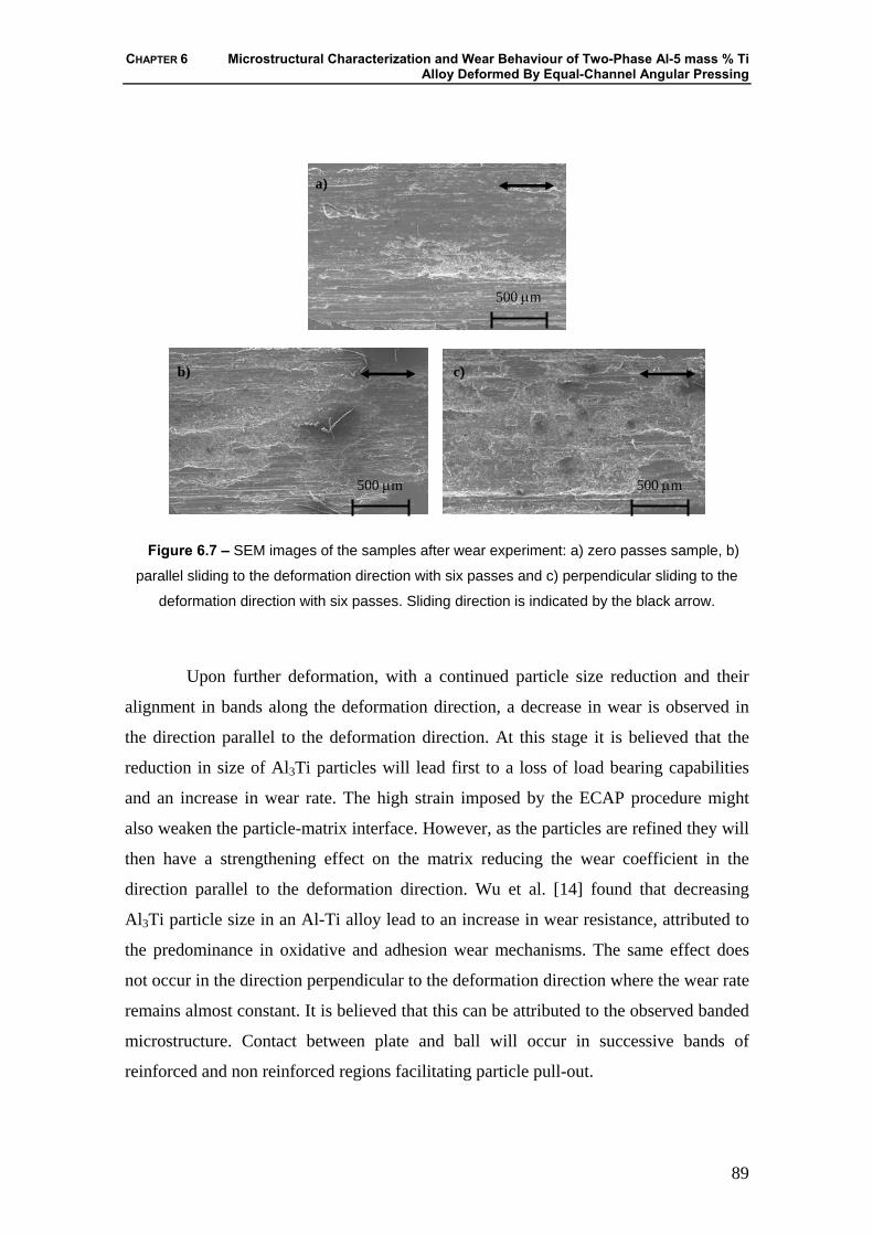
CHAPTER 6 Microstructural Characterization and Wear Behaviour of Two-Phase Al-5 mass % Ti Alloy Deformed By Equal-Channel Angular Pressing
89
Figure 6.7 – SEM images of the samples after wear experiment: a) zero passes sample, b)
parallel sliding to the deformation direction with six passes and c) perpendicular sliding to the
deformation direction with six passes. Sliding direction is indicated by the black arrow.
Upon further deformation, with a continued particle size reduction and their
alignment in bands along the deformation direction, a decrease in wear is observed in
the direction parallel to the deformation direction. At this stage it is believed that the
reduction in size of Al3Ti particles will lead first to a loss of load bearing capabilities
and an increase in wear rate. The high strain imposed by the ECAP procedure might
also weaken the particle-matrix interface. However, as the particles are refined they will
then have a strengthening effect on the matrix reducing the wear coefficient in the
direction parallel to the deformation direction. Wu et al. [14] found that decreasing
Al3Ti particle size in an Al-Ti alloy lead to an increase in wear resistance, attributed to
the predominance in oxidative and adhesion wear mechanisms. The same effect does
not occur in the direction perpendicular to the deformation direction where the wear rate
remains almost constant. It is believed that this can be attributed to the observed banded
microstructure. Contact between plate and ball will occur in successive bands of
reinforced and non reinforced regions facilitating particle pull-out.
500 μm
a)
500 μm
c)
500 μm
b)
WEAR, CORROSION AND TRIBOCORROSION BEHAVIOUR OF AL-BASED COMPOSITES REINFORCED WITH AL-RICH INTERMETALLIC COMPOUNDS
90
6.4 – Conclusions
An Al-5 mass % Ti alloy was processed by ECAP from 1 up to 6 passes.
Microstructural and mechanical properties characterization was performed.
1) Al3Ti particle break-up and alignment in the deformation direction was
observed.
2) The increase of passes in the ECAP process for the Al- 5 mass% Ti alloy
increases the hardness of the alloy.
3) Reduction of wear resistance in the deformed alloys compared to the non
deformed alloy was found.
4) Anisotropic wear resistance was observed perpendicular and parallel to the
deformation direction by ECAP. With a recovery of wear resistance in the sliding
direction parallel to the deformation direction.
Acknowledgments
This study was partially supported by the Grant-in-Aid for 21st Century COE
Program “Advanced Fiber Science and Textile Technology” by the Ministry of
Education, Culture, Sports, Science and Technology of Japan.
6.5 – References
[1] S.K. Das, Al-Rich Intermetallics in Aluminum Alloys, in Intermetallic
Compounds, ed J.H Westbrook and R.L. Fleischer; Volume 3, Wiley, 2000, p.179.
[2] V.M. Segal, V.I. Reznikov, A.E. Drobyshevskiy V.I. Kopylov, Russian
Mettalurgy, (Engl. Transl.) 1 (1981) 99.
[3] V.M. Segal, Mater. Sci. Eng. A 197 (1995) 157.
[4] M. Furukawa, Z. Horito, M. Nemoto and T.G. Landon, J. Mater. Sci. 36 (2001)
2835.
[5] M. Murayama, Z. Horita and K. Hono, Acta Mater. 49 (2001) 21.
CHAPTER 6 Microstructural Characterization and Wear Behaviour of Two-Phase Al-5 mass % Ti Alloy Deformed By Equal-Channel Angular Pressing
91
[6] D.H. Shin, W.J. Kim, W.Y. Choo, Scripta Mater 41 (1999) 259.
[7] D.H. Shin, C.W. Seo, J. Kim, K.T. Park, W.Y. Choo, Scripta Mater 42 (2000)
695.
[8] D.H. Shin, B.C. Kim, K.T. Park, W.Y. Choo, Acta Mater 48 (2000) 3245.
[9] M. Murayama, Z. Horita, K. Hono, Acta Mater 49 (2001) 21.
[10] V.V. Stolyarov, R. Lapovok, I.G. Brodova, P.F. Thomson, Mater Sci Eng A357
(2003)159.
[11] D.Ma, J. Wang, K. Xu. Mater Letters 56 (2002) 999.
[12] I. Sabirov, O. Kolednik, R.Z. Valiev, R. Pippan, Acta Mater. (2005).
[13] J.M. Wu, S.L. Zheng, Z.Z. Li, Y. W. Zeng, Wear 232 (1999) 25.
[14] J.M. Wu, Z.Z. Li , Wear 244 (2000) 147.
[15] Y. Watanabe, N. Yamanaka, Y. Fukui, Metall. Mater. Trans. A 30A (1999)
3253.
[16] Y. Iwahashi, M. Furukawa, Z. Horita, M. Nemoto, T.G. Langdon, Metall. Mater.
Trans. A 29A (1998) 2245.
[17] K. Nakashima, Z. Horita, M. Nemoto, T.G. Langdon, Acta Mater. 46 (1998)
1589.
[18] Z. Zhang, Y. Watanabe, I. Kim, Mater. Sci. Tec. 21 (2005) 1.

CHAPTER7 General Discussion and Comparison of the Experimental Results
93
CHAPTER 7
General Discussion and Comparison of the Experimental Results
In this chapter, the experimental results presented in each previous chapter of
three to six on the subject of corrosion and tribocorrosion behaviour of the Al/Al3Ti and
Al/Al3Zr FGMs and wear behaviour of Al-5 mass % Ti alloy deformed by ECAP are
compared and discussed, in order to understand the relationships between them.
The corrosion behaviour of Al/Al3Ti and Al/Al3Zr FGMs was evaluated through
OCP, potentiodynamic polarization and EIS in a 0.6 M NaCl solution at room
temperature (Figures 3.2 and 3.3). The analysed region on the ring FGM obtained by
centrifugal casting was the outer region of the perpendicular plane to rotation axis
(OP1). In OP1, the volume fraction occupied by Al3Ti or Al3Zr particles increases from
the inner to the outer regions of the FGM rings. Moreover, the samples 60 and 120 G
have absence of particles from around the middle to the inner region of the rings in both
the Al/Al3Ti and Al/Al3Zr FGMs. The concentration of particles is larger in the outer
region (Figure 3.7). It should be referred that, the outer zones of the Al/Al3Ti FGMs
group are similar in terms of area fraction of particles, in opposing of the Al/Al3Zr FGM
group, where the 30 G sample presents smaller concentration of particles in the outer
region than the 60 and 120 G samples.
By monitoring the corrosion potential (Ecorr) for the period of 60 minutes, all
samples revealed an increase in the corrosion potential with the time, indicating the
formation of a passive film (Figure 3.2). The Al/Al3Ti FGMs group shows a similar
behaviour, in terms of thermodynamic stability. In this group, the sample obtained with
centrifugal force of 60 G reveals a little better behaviour. On the contrary, the Al/Al3Zr
FGMs group presents a more dispersed behaviour. Here, 30 G sample reveals a Ecorr
WEAR, CORROSION AND TRIBOCORROSION BEHAVIOUR OF AL-BASED COMPOSITES REINFORCED WITH AL-RICH INTERMETALLIC COMPOUNDS
94
clearly higher than the 60 G and 120 G samples. The more active corrosion potential
exhibited by these last samples reflects its less thermodynamic stability and therefore its
higher corrosion tendency.
The anodic polarisation curves revealed accord with the OCP results (Figure
3.3). Al/Al3Ti FGMs group is also very similar. In case of Al/Al3Zr FGMs group, the
samples obtained with 60 G and 120 G revealed the worst corrosion behaviour. This
phenomenon can be explained by the low segregation of particles found in the sample
obtained with 30 G. This group shows that the degradation of samples intensifies with
the increase of the concentration particles.
It is well known that corrosion attack is a function of matrix composition and
increases with reinforcement volume concentration [1]. Moreover, in aluminium matrix
composites both, ceramic particles/matrix and intermetallic compounds/matrix
interfaces are preferential sites of localized attack with pits of larger size. The pits
nucleation preferentially begins at the matrix/ceramic particles and matrix/intermetallic
compounds interfaces [1-3].
As reported in [4], the aluminium alloys containing intermetallic phases can be
characterized as undergoing localized attacks basically in the zones surrounding
particular types of intermetallic compounds. This type of attack leads to the formation
of large numbers of pits, which extend to a large proportion of the exposed surface area.
This process is associated with the cathodic character of the precipitates of Al3Ti and
Al3Zr [5], in nearness to which this type of attack is produced. The cavities formed are a
consequence of the loss of contact between reinforcements and the matrix.
Thus, the higher degradation of the outer region of Al/Al3Zr FGMs samples
obtained with 60 G and 120 G is explained by the higher concentration of particles. The
cathodic area is highest in this region compared with anodic area.
The effect of corrosion of the matrix in the zone surrounding the precipitates of
Al3Ti and Al3Zr was clearly observed in the scanning electron microscopy (SEM)
image. The morphology of the FGMs samples revealed a large degradation, in the
adjacent regions to the reinforced particles, but the particles are not attacked (figures 3.4
and 3.5). In case of Al/Al3Zr FGMs group, the concentration of small particles appears
to be higher than that found in Al/Al3Ti sample. In a similar manner, both FGMs groups
after polarisation test suffered a high degradation in the adjacent regions to the particles.
CHAPTER7 General Discussion and Comparison of the Experimental Results
95
The corrosion current density (icorr) was not possible to estimate by extrapolating
linear portions of the anodic and cathode branches, known as Tafel plots, due to the
high noise level present in the anodic polarisation curves.
Experimental EIS results from Al/Al3Ti and Al/Al3Zr FGMs after 1, 3, 6 and 10
days were analysed with base in an equivalent circuit described in Chapter 3 (Figure
3.11). Evaluating the Al/Al3Ti FGMs group, the 60G sample presents the highest
polarization resistance (Rp) and resistance of the passive film (Rpf), indicating its
relatively better corrosion behaviour. So that, this sample reveals the lowest capacitance
of the passive film (Cpf), revealing its better protective character. These results are in
total accordance with the OCP and the potentiodynamic polarization results, which
showed a little better corrosion behaviour for this sample. With relationship to the group
of Al/Al3Zr FGMs, this presented an abrupt decrease in the Rp values from 1 to 3
immersion days. Also, from 3 up to 10 days of immersion the samples showed a slight
decrease of Rp. An exception occurs with the sample obtained with 60 G, which reveals
an increase in the Rp from 3 to 10 days of immersion time. The Rpf decrease along of the
10 days of immersion for all samples, indicate the degradation of the passive film. This
phenomenon is confirmed by the evolution of the Cpf in all Al/Al3Zr FGMs samples,
which increase with the immersion time. As suggested by the OCP and potentiodynamic
polarisation tests, 30 G sample show the highest Rpf and the lowest Cpf values indicating
the better corrosion behaviour of this group.
In terms of the corrosion behaviour, the Al/Al3Ti FGMs 60 G and Al/Al3Zr
FGMs 30 G samples present the better corrosion resistance, inside of the corresponding
group.
Following, the investigation of the synergic effect of corrosion-wear in the same
samples and same regions was performed (Chapter 4). Results of tribocorrosion tests
obtained in FGMs samples show a similar evolution of the current with the time
(Figures 4.9 and 4.11). All samples show an increase in the current at the beginning of
sliding, corresponding to the initial contact between the counter body and the surface of
the sample. After this, the current density decreases until reaching the stable state. In the
Al/Al3Ti FGMs group, the 30 G sample achieves a stationary state more early. The
sample 120 G follows a similar behaviour, while the sample 60 G takes much more time

WEAR, CORROSION AND TRIBOCORROSION BEHAVIOUR OF AL-BASED COMPOSITES REINFORCED WITH AL-RICH INTERMETALLIC COMPOUNDS
96
to reach a stable state. At the end of sliding, the 60 G samples have current density
values similar to 30 G and higher than 120 G sample which presents the lowest current.
In terms of friction coefficient all samples show similar behaviour, μ varies
between 0.4 and 0.5, the lowest value corresponding to the 120 G sample. This sample
presents the lowest average friction coefficient and the lowest current density.
The results of tribocorrosion tests obtained for the Al/Al3Zr FGMs group (Figure
4.11), the 30 G and 60 G samples show similar current density values during the sliding,
which is twice when compared with the 120 G sample. In this group, the μ varies
between 0.4 and 0.6. The sample with the more stable μ during the sliding time is the 30
G sample. The sample with the lowest μ is the 60 G sample. μ decreases abruptly in the
first 3 minutes of wear and then stabilizes. In the case of the 120 G sample, the μ is very
unstable during the sliding time and is the highest when compared with the other
samples.
The morphologies of SEM of the FGM samples indicated abrasive scratches and
cracking of the intermetallic platelets on the deformed wear zone. Plastic deformation
was clearly visible on the deformed wear zone i.e, the wear scar shows signs of severe
wear (Figures 4.10 and 4.11).
Al/Al3Ti FGMs samples present slightly lower friction coefficient and lower
current densities when compared with Al/Al3Zr FGMs samples.
Regarding to the synergism between the wear and corrosion phenomena, all the
samples show insignificant removed volumes by electrochemical process (Vchem) when
compared to the amount of material removed by the mechanical process (Vmech). This
indicates that the tribocorrosion process in these materials is mainly governed by the
mechanical wear (Figure 4.13). It is also observed that the samples having a large Vmech
show a larger Vchem, indicating probably that there is an increase in the corrosion rate
due to wear. Other important characteristic is that the samples with a less total wear
volume are the 120 G ones. This phenomenon can be explained by the higher volume
fraction of particles obtained from a higher applied centrifugal, such as occurs in all 120
G samples. In general terms, better tribocorrosion behaviour was found in the samples
containing the highest concentration of reinforcing particles.
CHAPTER7 General Discussion and Comparison of the Experimental Results
97
It is important to refer that the Al/Al3Ti FGMs 60 G and Al/Al3Zr FGMs 30 G
samples that show better corrosion behaviour, are those showing a worst behaviour in
terms of tribocorrosion.
In the tribocorrosion tests, the action of the mechanical loading is much more
aggressive than the corrosion effect. Also, the presence of hard particles has a positive
effect in terms of resistance to mechanical wear, as shown by several authors in studies
of Al-based MMCs in dry sliding [6,7]. The addition of hard particles, until a
convenient percentage and size improved the wear rate of the Al alloy. This behaviour
is due to the capacity of support of load of the reinforcement particles. However if the
amount of particles is too high they will fracture, decreasing the wear resistance of the
material [6-9]. In Al-based FGMs, the reinforcing particles with higher bulk density
than liquid aluminium segregate towards the outer regions as a result of the forces
created during the centrifugal casting process. Additionally, hardness values, wear test
results, and wear track analysis were consistent with the microstructural gradient
observed in composites. In effect, the higher volume density of reinforcing particles in
the outer regions of the centrifugally cast samples translates into a higher hardness and
higher overall wear resistance on those regions [10-13].
The tribocorrosion processes of Al/intermetallics compounds FGMs are mainly
governed by mechanical wear. It was verified that exits a synergism between the wear
and the corrosion process; corrosion will increase together with wear rate.
The study of the corrosion and tribocorrosion behaviour was just performed in
Al/Al3Zr FGMs group in the plan perpendicular to the rotating direction (OP2) in two
regions, outer and inner of the ring (Chapter 5).
In this case, all samples, except the 120 G inner, reveal an increase in the
corrosion potential with the immersed time, indicating the formation of a passive film
(Figure 5.4). The Al/Al3Zr FGMs 30 G and 60 G samples show a similar behaviour, in
terms of thermodynamic stability. The sample obtained with 30 G reveals a little better
behaviour, (as seen in OP1) and 120 G inner reveals the worst corrosion behaviour. The
anodic polarisation curves obtained for all Al/Al3Zr FGMs samples are similar, except
for the sample 120 G inner. Thus, these results appear to be in accordance with OCP
results.
WEAR, CORROSION AND TRIBOCORROSION BEHAVIOUR OF AL-BASED COMPOSITES REINFORCED WITH AL-RICH INTERMETALLIC COMPOUNDS
98
Results of tribocorrosion tests obtained in Al/Al3Zr FGMs samples show a
similar evolution of the current with the time (Figure 5.5). All samples show an increase
in the current density at the beginning of sliding, corresponding to the initial contact
between the counterbody and the surface of the sample. After this, the current density of
all samples decreases attempting to reach a steady state. An exception occurs with 60 G
and 120 G outer samples. It is also possible to note that at the end of sliding period, the
current density of all samples decrease reaching values similar to those observed before
sliding. This behaviour shows a clear negative influence of the sliding processes on the
deterioration of surface samples. In comparison with the plane OP1, the plane OP2 has
larger values of Q, in other words, higher electrochemical degradation. Additionaly, the
60 G sample show a larger Q. The observation of the larger Q of 120 outer sample in
OP2, is in opposition with smaller Q in OP1.
In terms of μ, all samples show a similar behaviour, i.e. increases until achieving
a steady state. Once again and similarly as the current density evolution, an exception
occurs with the 60 G outer and 120 G outer samples. The μ of these last samples
monotonically increase with the sliding time.
Regarding the tribocorrosion phenomena, all the samples show negligible Vchem
in front to large Vmech (Figure 5.6), as in OP1 (Figure 4.13 b). This indicates that the
tribocorrosion process is mainly governed by the mechanical wear. Other important
observation is that samples exhibiting highest electrochemical degradation are the 60 G
outer and 120 G outer. Additionally, the sample with the highest mechanically removed
volume is the 60 G outer. This is in contrast with the result found in the plane OP1. It
was expected that 60 G outer had lesser removed volume total that the 30 G samples
and 60 G inner. So, in this sample, the tribocorrosion test might have been performed in
a region of porosity which is able of increasing the degradation by chemical action and
beyond of the action of third body in the tribological contact. In 30 G and 120 G
samples, as expected, the inner regions were fairly depleted of reinforcement particles
and, thus, were subject to higher wear rates.
The values of the μ and removed volume total for OP1 are lower than found in
OP2 for Al/Al3Zr FGMs.
CHAPTER7 General Discussion and Comparison of the Experimental Results
99
The morphology of wear tracks of all Al/Al3Zr FGMs samples show some third
body particles and/or wear debris accumulate at the wear scar after tribocorrosion tests
(Figure 5.7).
In Chapter 6 was described a study of wear resistance of Al-5 % mass Ti alloy
deformed by ECAP for 1, 3 and 6 passes.
An increase of the hardness since 0 up to 6 passes occurs. However, this increase
is more pronounced between 0 to 1 passes becoming then almost linear from 1 to 6
passes (Figure 6.5).
The first remark to be done relates to the fact that the alloys possess a very low
wear resistance (Figure 6.6). A significant increase of the wear occurs from 0 to 1
passes can also be evidenced in the perpendicular sliding but also in the parallel to the
direction of deformation by ECAP. Considering the values of the wear coefficient
values in the sliding direction perpendicular to the direction of deformation, K⊥, one can
see that they are higher than those referring to the wear values in parallel sliding
direction, K⎥⎥. The values of K⊥ show a variation of the next values between themselves,
while, the values of K⎥⎥ tend to decrease from 1 to 6 passes.
The increase of the number of passes causes high degree of deformation and a
microstructure that increases the material hardness. However, as shown by the obtained
results, it does not confer an increase of the wear resistance.
In fact, it was expected that an increase of the number of passes, despite
increasing the hardness, would also increase the wear resistance, which was not the case
in this work.
7.1 – References
[1] A. Pardo, M.C. Merino,S. Merino, F. Viejo, M. Carboneras,R. Arrabal, Corros.
Sci. 47 (2005) 1750.
[2] A. Pardo, M.C. Merino, R. Arrabal, F. Viejo, M. Carboneras, J.A. Muñoz,
Corrosion Science (2005), in press.
[3] A. Pardo, M.C. Merino, R. Arrabal, S. Feliú Jr., F. Viejo, M. Carboneras,
Electrochim Acta (2006), in press.
WEAR, CORROSION AND TRIBOCORROSION BEHAVIOUR OF AL-BASED COMPOSITES REINFORCED WITH AL-RICH INTERMETALLIC COMPOUNDS
100
[4] A. Aballe, M. Bethencourt, F.J. Botana, M.J. Cano, M. Marcos, Corros. Sci. 45
(2003) 161.
[5] N. Birbilis, R. G. Buchheit, J. Electrochem. Soc. 152 (2005) B140.
[6] D.P. Mondal, S. Das, R.N. Rao, M. Singh, Mater. Sci. Eng. A 402 (2005) 307
[7] H. Sevik, S.C. Kurnaz, Mater. Des. 27(2006) 676.
[8] M. Kök, Composites: Parte A 37 (2006) 457.
[9] Y. Sahin, Mater. Des. (2006) in press.
[10] J.R. Gomes, A.S. Miranda, D.F. Soares, A.E. Dias, L.A. Rocha, S.J. Crnkovic,
R.F. Silva, Ceramics Trans. 114 (2000) 579.
[11] J.R. Gomes, A.S. Miranda, L.A. Rocha, S.J. Crnkovic, V. Silva, R.F. Silva, Int.
J. Appl. Mech. Eng. 7 (2002) 791.
[12] J.R. Gomes, L.A. Rocha, S.J. Crnkovic, R.F. Silva, A.S. Miranda, Mater. Sci.
Forum 423 (2003) 91.
[13] Z.H. Melgarejo, O. M. Suárez, K. Sridharan, Scripta Mater (2006) in press.
CHAPTER 8 Conclusions
101
CHAPTER 8
Conclusions
A study on corrosion, tribocorrosion and wear in Al/intermetallic composites
was presented in this work. The main conclusions of this work were presented
throughout this these and the most important writing here.
The corrosion resistance of Al/intermetallic FGMs is influenced by galvanic
effects between the intermetallic particles and the metal matrix that present divergent
electrochemical characteristics. In general terms, the corrosion resistance of FGM
appears to increase when a low segregation of particles is found in the material,
associated to low applied centrifugal forces, i.e., the higher degradation of the outer
region of Al FGMs samples obtained with larger centrifugal forces is explained by the
higher concentration of particles. The cathodic area is highest in this region compared
with anodic area. This is an indication that the presence of the reinforcing intermatallics
promotes a superior electrochemical degradation of the samples, due to the galvanic
couple effects between the intermetallic compounds and the metallic matrix.
The tribocorrosion processes of Al/Al3Ti and Al/Al3Zr FGMs are mainly
governed by mechanical wear. Better tribocorrosion behaviour was found in the samples
containing the highest concentration of reinforcing particles. And it was verified that
exits a synergism between the wear and the corrosion process in which this last is
increasing with the wear acts.
The increase of passes in the ECAP process for the Al-5 mass % Ti alloy
increases the hardness of the alloy. However, in comparison with the not deformed
alloy, the wear resistance diminishes in the deformed alloys both in the perpendicular
and in the parallel way of the deformation direction by ECAP.

CHAPTER 9 Perspectives of Future Work
103
CHAPTER 9
Perspectives of Future Work
During this research, phenomena not fully reported in this thesis occurred. Thus,
an extensive study for provide complementary information would be required. For
better comprehension of the concept the Al-based composites containing Al-rich
intermetallic compounds, it would be interesting to do the following:
• Development of a theoretical model (3D) to predict the redistribution of the
intermetallic platelets in the molten aluminium matrix for different rotations speeds.
The same procedure should be followed to predict, the orientation of platelets on Al-Ti
alloy deformed by ECAP;
• Study the effect of the presence of other alloying elements on the Al-Ti and Al-
Zr alloys;
• Study the effect of the variation of the Ti and Zr content on the respectively
alloys (Al-Ti and Al-Zr) to analyze its influence on the volume fraction distribution of
platelets in the composite;
• Production of the FGMs with appropriate dimensions for mechanical tests and
characterization of mechanical properties;
• General corrosion and tribocorrosion behaviour of the Al-Ti deformed by ECAP.
