this service manual covers nostalgic floor models with...
TRANSCRIPT

Copyright ©2007 All Rights Reserved Rock-Ola Manufacturing Corporation 2335 208th Street, Torrance, CA 90501
This Service Manual covers
Nostalgic Floor Models with Coin-Acceptor
This document contains information
proprietary to Rock-Ola Manufacturing Corporation and may not be reproduced,
published or distributed in any form or disclosed in whole or in part without
written authorization.
P/N 60761

iPod® is a Trademark of Apple Computer Corp. i
Table of Contents
Section A Jukebox Specifications Section B Set-up and Preparation Major Component Location .................................................................... B - 2 Unpacking the Phonograph.................................................................... B - 3 Power Up................................................................................................ B - 3 Loading Program Pages ........................................................................ B - 4 Loading Compact Discs ......................................................................... B - 5 Repacking/Moving.................................................................................. B - 6 Section C Connecting Speakers, Telephone Adaptor Kit, I.R.
Remote Detector and Paging Microphone External Speaker Connections .............................................................. C - 2 Speaker Loading .................................................................................... C - 2 Connection Examples ............................................................................ C - 3 Installation of the Telephone Adaptor Kit for Removable Volume Control ....................................................... C - 6 Installation of the I.R. Remote Detector and Harness Assembly........... C - 7 Connecting A Paging Microphone ......................................................... C - 8 Installation of the iPod® Dock Kit............................................................ C - 9 Section D Amplifier Description and Operation Amplifier Description .............................................................................. D - 2 Indicator LED’s ....................................................................................... D - 3 Signal Inputs and Outputs...................................................................... D - 3 Amplifier Feature Description................................................................. D - 4 Setting The Amplifier .............................................................................. D - 4 Section E Operation and Programming Overview Normal Operation................................................................................... E - 2 Control Computer Buttons...................................................................... E - 3 Programming, Service and Diagnostics Features Overview Suspend Mode................................................................................. E - 4 Service Mode................................................................................... E - 4 Setup Mode ..................................................................................... E - 5 Diagnostic and Error Reporting Features .............................................. E - 6 Quick Find Reference Programming Chart............................................ E - 7 Quick Find Reference Programming Definitions Disc Mapping ................................................................................... E - 8 Page Options ................................................................................... E - 8 Play Options .................................................................................... E - 9 Auto Play.......................................................................................... E - 9 Free Play........................................................................................ E - 10 Pricing............................................................................................ E - 11 Set-up 1 ......................................................................................... E - 12 Set-up 2 ......................................................................................... E - 13 Set-up 3 ......................................................................................... E - 14

iPod® is a Trademark of Apple Computer Corp. ii
Accounting............................................................................................ E - 14 Popularity ....................................................................................... E - 15 Disc Errors ..................................................................................... E - 15 Remote Control.............................................................................. E - 15 Test Mode...................................................................................... E - 16 Auto test......................................................................................... E - 17 TCM Setup.................................................................................... E - 18 Amp Setup ..................................................................................... E - 21 Quick Find Reference Programming Flow Charts Set up Mode Flow Chart ................................................................ E - 23 Disc Mapping ................................................................................. E - 24 Page Options ................................................................................. E - 26 Play Options .................................................................................. E - 27 Auto Play........................................................................................ E - 28 Free Play........................................................................................ E - 33 Pricing............................................................................................ E - 36 Set-up 1 ......................................................................................... E - 38 Set-up 2 ......................................................................................... E - 41 Set-up 3 ......................................................................................... E - 43 Accounting ..................................................................................... E - 44 Popularity ....................................................................................... E - 48 Disc Errors ..................................................................................... E - 49 Remote Control.............................................................................. E - 51 Test Mode...................................................................................... E - 54 Auto test......................................................................................... E - 59 TCM Setup.................................................................................... E - 61 Amp Setup ..................................................................................... E - 65 Section F Routine Service Accounting...............................................................................................F - 2 Popularity ................................................................................................F - 4 Disc Changing.........................................................................................F - 5 Appearance and Preventative Maintenance...........................................F - 5 Checking For Errors ................................................................................F - 6 Section G Maintenance Maintenance........................................................................................... G - 2 General Maintenance Considerations.................................................... G - 2 Preventative Maintenance...................................................................... G - 2 Mechanical Adjustments Magazine Adjustments .................................................................... G - 4 CD Player Adjustments.................................................................... G - 5 Title Page Adjustments.................................................................... G - 6 Coin Mechanism Cleaning ..................................................................... G - 6 Replacing Fluorescent Lamps ............................................................... G - 6

iPod® is a Trademark of Apple Computer Corp. iii
Section H Troubleshooting and Repair Troubleshooting and Repair Overview................................................... H - 2 Troubleshooting Charts Power and Start up Problems.......................................................... H - 3 Credit Problems ............................................................................... H - 4 Play Problems.................................................................................. H - 4 Page Problems ................................................................................ H - 5 Fuse and LED Locations Power Supply Fuses........................................................................ H - 6 Keyboard LEDs................................................................................ H - 6 Digital Amplifier & Power Supply LEDs & Connections................... H - 6 Block Diagrams Amplifier Block Diagram .................................................................. H - 7 CPU Block Diagram......................................................................... H - 8 CD Player Start-Up and Run Diagram ............................................ H - 9 Power Distribution Block Diagram................................................. H - 10 Start up and Diagnostic Mode Operation............................................. H - 11 Test Mode ............................................................................................ H - 12 Viewing Error Codes ............................................................................ H - 12 Using Error Codes CPU (Input) Error Codes ............................................................... H - 13 Keyboard Error Codes................................................................... H - 14 Mechanism Error Codes................................................................ H - 15 Page Unit Error Codes .................................................................. H - 15 Running Tests CPU Tests ..................................................................................... H - 16 Keyboard Test ............................................................................... H - 18 Display Test ................................................................................... H - 18 Pages Test..................................................................................... H - 19 Mechanism Tests........................................................................... H - 19 Amplifier Troubleshooting .................................................................... H - 21 Section I Major Component Schematics CPU.......................................................................................................... I - 2 Amplifier/Power Supply ............................................................................ I - 8 Audio Output Panel ................................................................................ I - 20 Keyboard/Display ...................................................................................I - 21 Removable Volume Control ................................................................... I - 23 Crossover ............................................................................................... I - 24 Transformer............................................................................................ I - 25 Lighting Wiring Diagram......................................................................... I - 26 Primary Power Block Diagram ............................................................... I - 27 Section J Common Accessories (optional) Section K Parts Catalog

Section
A
Jukebox Specifications
A - 1

Section A Specifications
Rock-Ola Mfg. Corp. Operation and Service ManualDigital CD Nostalgic Models
A - 2
Jukebox Specifications
CD-8 BUBBLERCD-4 MODELS
CD-6 PEACOCK
Dimensions: Uncrated: Height 61” 64 1/4” Width 33 1/2” 33 1/2” Depth 26 3/4” 26 3/4” Crated: Height 73” 73” Width 39” 39” Depth 32” 32”
Weight: Uncrated 284 Lbs. 287 Lbs.
Crated 341 Lbs. 344 Lbs.
Amplifier:Output Power: Main amplifier 450 peak music power
External amplifier 450 peak music power
Protection: Speaker overloadHigh temperatureOver voltageUnder voltageAutomatic, self resetting
Frequency: 30 - 20,000 Hz
Input Power: Domestic / ExportVoltage: 115V / 230VFrequency: 60 Hz / 50 Hz
MaximumPower Consumption:
WattsStandby / Max
225 / 800
Speakers: (2) Tweeter 3”(2) Midrange 6-1/2”(1) Woofer 10” dual voice coil

Section
B
Setup and Preparation
- Major Component Location- Unpacking the Phonograph- Power up- Loading Program Pages- Loading Compact Discs- Repacking/Moving
B - 1

Section B Set-up and Preparation
Rock-Ola® Mfg. Corp. B - 2 Operation and Service Manual Digital CD Nostalgic Models
Thank you for purchasing your new Rock-Ola SyberSonic Compact Disc Jukebox. This manual will provide instructions for operating your new phonograph. If after reading the manual you have any ques-tions about the operation of the jukebox, please call your authorized dealer. With a little practice, opera-tion will become natural. Start by identifying the major components in the jukebox. Major Component Location 1. Computer 2. Dual Digital Amp & Power Supply 3. Volume Control 4. CD Player
5. CD Magazine 6. Coin Mechanism 7. Service Switch 8. Crossover
9. Speaker 10” dual voice coil 10. Scan/Cancel Switch 11. Power Cut Off Switch 12. Power Transformer
Figure 1B
WARNING Do not apply AC power until the follow-ing instructions indicate you should.
ADVERTENCIA No aplicar corriente A/C hasta que las siguientes instrucciones in-diquen que puede.
AVERTISSEMENT
Ne mettez pas sous une tension en courant alternatif avant que les in-structions suivantes le préconisent.

Section B Set-up and Preparation
Rock-Ola® Mfg. Corp. B - 3 Operation and Service Manual Digital CD Nostalgic Models
Unpacking the Phonograph • Open Door.
• Remove the shipping braces (tape) from the title display assembly mounting clips.
The CD player is extremely sensitive to static discharges. Always ground yourself before touching the player and never touch the eye. The CD
player itself has no adjustments. The only mainte-nance required is occasional lens cleaning.
El Toca-discos CD es extremamente sensitivo a descargas de electricidad estática. Siempre toque “tierra” antes de tocar el Toca-discos y nunca toque el ojo (lente). El Toca-discos CD no tiene ajustes en sí. El único mantenimiento requerido es el limpiar el ojo ocasionalmente. Le lecteur de disque compact est extrêmement sensible aux décharges statiques. Veuillez tou-jours vous mettre à la masse avant d’y toucher et ne touchez jamais à l’oeil. Le lecteur de disque compact ne présente aucun réglage. Le seul en-tretien nécessaire est un nettoyage régulier de la lentille.
• Remove shipping bolts from mechanism.
• Remove rubber band from CD clamper plate. (Retain for future use).
• Remove shipping brace (tape) from the dol-lar bill validator (if installed). Make sure the bill stacker is properly seated.
• Plug System Power Harness into J7 of the Power Supply Assembly.
• Make sure that no items/objects can inter-fere with the movement of the disc maga-zine and the clamper plate. Also ensure the title display pages movement cannot be ob-structed in any way.
Power up Note: For safety, Rock-Ola’s SyberSonic Sys-tem incorporates an automatic mechanism inter-lock system.
Whenever the door is opened, the mechanism will enter a “suspend mode” and the machine’s display will indicate: “DOOR OPEN” on the top line and the bottom line will scroll the message: “Press Scan Switch to Continue. Warning: Mechanism Could Start Anytime.”
Figure 4B - Power Cut Off Switch Ensure the Main Power Switch (on back of machine) is Off. Connect Power Cord to Power Supply and plug into a properly polarized and grounded outlet.
Figure 5B - Main Power Switch
WARNING Before applying power, put POWER CUT OFF SWITCH in the OFF position. (Figure 4B).
ADVERTENCIA Antes de encender el aparato, poner el inter-ruptor de encendido y apagado en la posi-ción OFF (Figure 4B).
AVERTISSEMENT
Avant de mettre sous tension, mettez L’INTERRUPTEUR DE TENSION sur la posi-tion éteinte “OFF”. (Figure 4B).
DOOR OPEN Press Scan Switch to …

Section B Set-up and Preparation
Rock-Ola® Mfg. Corp. B - 4 Operation and Service Manual Digital CD Nostalgic Models
Ensure Service Switch (Fig 6B) is in the service position. Turn main power switch on. (Fig. 5B). Move the Power Cut off Switch (Fig. 4B) to the On position. Press the Scan/Cancel button once. Magazine should move 3 complete revolu-tions, then stop in the HOME Position. (With the gripper bow in the wide opening of the maga-zine). See the sections covering machine installation, disc installation, machine programming and ma-chine servicing for specific service information.
Figure 6B - Service Switch
Loading Program Pages To turn the title pages, set the Service Switch (Fig. 6B) to the normal operation position and use the [<] and [>] buttons on the keyboard.
WARNING Do not attempt to turn the program pages by hand. The pages must be turned using the [<] and [>] buttons on the keyboard.
ADVERTENCIA No intente pasar las páginas de programa manu-almente. Las páginas deben ser pasadas usando los botones (<) y (>) en el teclado.
AVERTISSEMENT N’essayez pas de tourner les pages de pro-gramme manuellement. Tournez les pages à l’aide des touches [<] et [>] figurant sur votre clavier.
1. Unplug the motor/switch harness connector
then release the catches on either side of the title display. Remove by pulling out at the top and lifting out. Rotate the pages by turning the black gear on the underside of the rack.
2. There are 2 ways to display the titles:
• If you are installing 1 to 50 discs, the single strips are used, and the numbers are installed in the square as shown starting with “00”.
• If you are installing 51 to 100 discs, use the full size split title strips and install the numbers in both top and middle ar-eas as shown. Start with “00” at the top and “01” in the middle.
3. Load your title strips first keeping the discs in their jewel boxes in the order they will be placed in the jukebox.
Figure 7B - Program Page Loading
WARNING Use of adapters or removal of the grounding pin of the plug may create a potential shock hazard and will defeat the surge protection devices causing erratic operation or destruction of the electronic assemblies and void all warranties.
ADVERTENCIA
El uso de adaptadores o el remover el pin de “tierra” del enchufe podrían crear un peligro potencial de shock, y derrotará al artefacto de protección contra cambios de corriente, causando operación errática, o destrucción de ensamblado electrónico, al igual que eliminar las garantias.
AVERTISSEMENT
L’utilisation d’adaptateurs ou le retrait de la broche de mise à la masse de la prise peut en-traîner un risque d’électrocution et faire échouer les dispositifs de protection de sec-teur entraînant ainsi un fonctionnement ir-régulier ou la destruction des montages élec-troniques, ainsi que l’annulation de toute ga-rantie.

Section B Set-up and Preparation
Rock-Ola® Mfg. Corp. B - 5 Operation and Service Manual Digital CD Nostalgic Models
Loading Compact Discs To rotate the magazine, put the Service Switch (Fig. 6B) into the SERVICE position and then push the red Scan/Cancel button located on the playing mechanism.
Load discs to match the jackets with the label side facing to the left of the cabinet. Be careful not to scratch or smudge the compact discs when loading. Continue the process until all the jackets and discs are loaded.
Figure 8B - Compact Disc Loading
Repacking/Moving
1. Remove the discs.
2. Select disc “0001”
3. When the disc clamping plate comes down on the CD player, remove power.
4. Unplug the connector at J7 on the Power Supply.
Install the shipping bolts through the mechanism base on each side and completely tighten.
Note: The mechanism base must be in contact with the wooden platform and the springs must be fully compressed.
Figure 9B - Mechanism
WARNING Do not attempt to rotate the magazine by hand. The magazine may be rotated with the red scan/cancel switch only. It is located on the top of the mechanism.
ADVERTENCIA No intente rotar el magazine manualmente. El magazine puede ser rotado solamente con uso del interruptor rojo scan/cancel. Localizado en la parte superior del mecanismo.
AVERTISSEMENT N’essayez pas de tourner le magasin manuellement. Le magasin doit être tourné à l’aide du commutateur rouge balay-age/annulation uniquement. Il est situé sur la partie supérieure du mécanisme.
WARNING
All shipping hardware must be correctly installed for shipping.
ADVERTENCIA Todo hardware debe ser instalado correcta-mente para el envío.
AVERTISSEMENT Tout le matériel de transport doit être installé correctement avant l’expédition.

Section B Set-up and Preparation
Rock-Ola Mfg. Corp. B - 6 Operation and Service Manual Digital CD Nostalgic Models
iPod® Volume Adjustment Any volume adjustment made for and during iPod® play does not adjust the volume for CD play. CD play volume adjustment is independent of iPod® volume adjustment. Likewise, adjusting the volume for and during CD play does not adjust the volume for the iPod® when it plays.
For additional information on iPod® program-ming and operation, see Section E of this man-ual.
A Note About Remotes The Nostalgic with iPod® Dock model may come with two remote controls: one for the juke-box itself (provided with all Nostalgic models), and one for iPod® control. Please keep in mind the following:
The jukebox remote control does not control any iPod® function or behavior, and
The iPod® remote does not control any other jukebox function or behavior beyond iPod®
selection, iPod® play volume, and iPod® power on and off.
Repacking/Moving
WARNING All shipping hardware must be correctly installed for shipping.
ADVERTENCIA
Todo hardware debe ser instalado correctamente para el envío.
AVERTISSEMENT Tout le matériel de transport doit être installé cor-rectement avant l’expédition.
1. Remove the discs. 2. Select disc “0001” 3. When the disc clamping plate comes down
on the CD player, remove power. 4. Unplug the connector at J7 on the Power
Supply. Install the shipping bolts through the mechanism base on each side and completely tighten. Note: The mechanism base must be in contact with the wooden platform and the springs must be fully compressed.
Figure 10B - Mechanism

S
e
c
t
i
o
n
C
Connecting Speakers
and Installing
Optional Hardware
C - 1
- Speaker Connections
- Installation of the Telephone Adaptor
Kit for Removable Volume Control
- Installation of the I.R. Remote Detector
and Harness Assembly
- Connecting a Paging Microphone
- Installation of iPod Dock

Section C Connecting Speakers & Optional Hardware
Rock-Ola® Mfg. Corp. Operation and Service Manual Digital CD Nostalgic Models
C - 2
The Dual Digital Amplifier has such high level of versatility that almost any installation is easily accomplished. There are two 450 watt peak music power stereo amplifiers built into the same housing. As shipped from the factory, the jukebox speak-ers are connected to the main or Internal ampli-fier such that they receive 100% of the power from one of the amplifiers. The second or Ex-ternal amplifier is available for connecting exter-nal speakers.
External Speaker Connections Installation examples are divided into 3 types: Example 1 – Jukebox plus 1 or 2 pairs of speakers in the same room with 1 volume con-trol. Example 2 – Jukebox in one room without speakers and 1 or more pairs of speakers in another room with separate volume controls. Example 3 – Jukebox plus 1 or 2 pairs of speakers in 1 room and 1 or more pairs of speakers in another room with 2 separate vol-ume controls. Connections to the speakers should be made with a #14 gauge minimum speaker wire with runs of less than 50 feet. Note: Observe the correct positive (+) and negative (-) polarity when making your speaker connections. Reversed polarity on any speaker will reduce fidelity. “Cross-channel” connections are not possible as neither channel has an in-verted output. All the connections to the amplifier cannot ex-ceed the amplifiers rated total of 450 watts peak music power. (225 watts per channel.) After all of the speakers are connected, play a selection and adjust the graphic equalizers as desired. Then run the system at the highest volume setting that the location will use. If the system plays without any distortion and does not “cut-out”, then the speaker load is appropriate
for the maximum volume, and the installation is complete. If the audio is distorted or ”cuts out”, at a high volume setting, there are three options. Reduce the bass, reduce the maximum volume setting, or move one or more speaker lines to a lower impedance terminal. See the programming sec-tion on ”Volume Limits” (Quick Find 78 in Sec-tion E of this manual.) to set the maximum vol-ume if necessary. Retest the system after mak-ing the changes. Note: The Digital SyberSonic Amplifier will automatically reduce the volume in order to con-tinue to operate even if the speaker load is in-correct however, there will be several seconds of silence when the overload condition occurs. This protection resets at power up. If greater flexibility in speaker loads is needed or 70-Volt CV speakers are to be used, an optional audio distribution assembly (P/N 70046-1A) may be installed.
Speaker Loading To achieve maximum volume and prevent ampli-fier overloading, calculate total impedance of speakers and hook-up to corresponding tap on Audio Output Panel. Typical configurations are shown in the table below. Additionally, several common installation scenarios are shown on the following pages.
Speaker Loading Chart
Number of Pairs 8-Ohm
Ext Speakers Connected to
Speakers Terminal No. None NA 1 Pair 4 2 Pairs 4 3 Pairs 2 4 Pairs 2 5 Pairs 1 6 Pairs 1 7 Pairs 1 8 Pairs 1

Section C Connecting Speakers & Optional Hardware
Rock-Ola® Mfg. Corp. Operation and Service Manual Digital CD Nostalgic Models
C - 3
Example No. 1 - Jukebox plus 1 or 2 pairs of speakers in the same room with 1 volume control.
Figure 1C
If all of the speakers are located in the same room and a single volume control is to be used, connect them to the audio output panel as shown. The Internal volume buttons will control the jukebox speakers and the External volume buttons will control the external speakers. Once the sound is “balanced” be-tween the external speakers and the jukebox speakers, the volumes may be “bridged” (QF 79) so as to preserve the balance and allow either the Internal or External volume buttons to be used.

Section C Connecting Speakers & Optional Hardware
Rock-Ola® Mfg. Corp. Operation and Service Manual Digital CD Nostalgic Models
C - 4
Example No. 2 - Jukebox in 1 room without speakers and 1 or more pairs of speakers in another room with separate volume controls.
Figure 2C
If there are no external speakers in the room with the jukebox, connect the external speakers to the out-put panel. Use the Internal volume buttons to operate the jukebox volume and the External volume but-tons to operate the external speakers.

Section C Connecting Speakers & Optional Hardware
Rock-Ola® Mfg. Corp. Operation and Service Manual Digital CD Nostalgic Models
C - 5
Example No. 3 - In this example, the audio output panel is plugged into the main amplifier and the jukebox speakers are plugged into the output panel using the 60685-A adaptor harness package provided in the service enve-lope. The speakers that are in the same room as the jukebox are connected to the output panel taking care to use the proper taps. If 2 pairs of 8 ohm speakers are connected to the 4 ohm tap, then the jukebox must be connected to the 1 ohm tap. If the jukebox speakers are too loud compared to the external speakers, they may be moved to the ½ ohm tap. The speakers in the second room are then connected to the output terminal block. The Internal volume buttons will control the jukebox and speakers in the first room. The External volume buttons will control the speakers in the second room.
Figure 3C

Section C Connecting Speakers & Optional Hardware
Rock-Ola® Mfg. Corp. Operation and Service Manual Digital CD Nostalgic Models
C - 6
Installation of the Telephone Adapter Kit (P/N 02413-01) for Removable Volume Control 1. Unplug and remove volume control from
back of phonograph. 2. Install cover plate over volume control hole. 3. Install a 6-pin phone jack not more than 1”
above the cover plate. (Installing the phone jack too high can cause interference with the title display assembly).
4. Route a 5-wire cable through wire hole in
the back of cabinet and connect to the phone jack noting wire colors.
Color Pin # Description BLU Pin 1 Internal Common YEL Pin 2 External Common GRN Pin 3 Cancel & Mute Common RED Pin 4 Mute, Int Down, Ext Down BLK Pin 5 Cancel, Int Up, Ext Up WHT Pin 6 Not used
5. Re-install the phone jack cover and plug the red phone wire into the newly installed phone jack.
6. Mount the volume control assembly in a
suitable location. 7. Mount the other phone jack to the right of
and not more than 12 inches from the vol-ume control module.
8. Connect the 5-wire cable to this phone jack
using the same wiring scheme as step 4. 9. Install cover on phone jack and connect the
12” jumper to phone jack and volume con-trol module.
10. Test for proper operation.
Cover Plate
Phone Jack 58803
Wire hole
5 wire cable
Back inside wall of phonograph
Red phone wire
5 wire cable
(from Computer)
12" Jumper 58902-A
Volume Control
Phone Jack 58803
Figure 4C
CONNECTOR BLOCK

Section C Connecting Speakers & Optional Hardware
Rock-Ola® Mfg. Corp. Operation and Service Manual Digital CD Nostalgic Models
C - 7
Installation of the I.R. Remote Detector and Harness Assembly 1. Plug I.R. remote harness into the Syber-
Sonic Computer assembly at the “Remote Sensor” location. (See diagram).
2. Route harness and I.R. detector assembly
through the cable cover hole on the back of the jukebox. Make sure not to route cable near any moving components.
3. For best results: Locate the detector eye on
the wall behind the jukebox. Depending on the location of the jukebox, it maybe neces-sary to try different heights on the wall to ob-tain the best result.
For locations that you are unable to mount the detector eye on the wall behind the jukebox, you may try mounting the eye on the back wall of the jukebox. The I.R. signal will bounce off walls and ceilings. Note: Infrared (I.R.) light transmitted from the hand held remote control can not be seen by the naked eye. The LED on the I.R. detector eye will flash when a button has been pressed to show that the I.R. detector eye is receiving a signal from the remote control. The remote does not work when the dome switch is in the service position.
Figure 5C
Remote Control
(61467-A)

Section C Connecting Speakers & Optional Hardware
Rock-Ola® Mfg. Corp. Operation and Service Manual Digital CD Nostalgic Models
C - 8
Connecting A Paging Microphone Rock-Ola’s Advanced SyberSonic Amplifier can accept virtually any paging microphone. Pic-tured below are wiring diagrams for the most common paging kits. Installation Instructions for Yoga Paging Kit #02379-02 are in Section J of this manual. The necessary connector is in-cluded with Rock-Ola paging kit. To use other paging kits you will need to acquire one (1) Amp part number 640250-4 housing (RMC P/N ST-11244) and four (4) Amp part number 640252-1 contacts (RMC P/N ST-11245) or equivalent.
Rock-Ola® 02379-01
Red
BlackShield
Yoga Microphone Kit 02379-02
Rowe®
NSM®
Generic Figure 6C - Connecting a Paging Microphone
The paging system works by sensing audio on the signal line. Whatever microphone is used, it must have some kind of switch to mute the au-dio when not in use. Set the Microphone gain switch to “LOW” and the gain control at midpoint. Press the talk but-ton on the microphone and speak into it. The “Status” LED on the amplifier should blink and the microphone signal should be heard in the speakers. Adjust the microphone gain control to the loudest level you want the location to be able to have. If more gain is necessary, turn the mi-crophone gain switch to “HIGH”.
CAUTION Be sure the gain control is turned down to avoid speaker damage from acoustical feedback.
PRECAUCIÓN
Asegúrese de que el control de ganancia esté en un ajuste bajo para evitar causar daños al altavoz debido a la retroacción acústica.
MISE EN GARDE Assurez-vous de baisser la commande du gain afin d’éviter les dommages causés aux haut-parleurs par la rétroaction acoustique.
Refer to the amplifier settings in section D for adjusting which channels to hear paging, the music level while paging, and length of time be-fore the music comes back up. Note: If the jukebox is idle with auxiliary back-ground music inputs off, there will be a short delay of approximately 2 seconds for the ampli-fiers to “wake up” when a paging signal is de-tected.

Section C Connecting Speakers & Optional Hardware
Rock-Ola® Mfg. Corp. Operation and Service Manual Digital CD Nostalgic Models
C - 9
Installation of the optional iPod® Dock Kit (P/N 02465)
Turn off the power and unplug the machine then open the jukebox door.
1. Remove the 21” fluorescent lamp just under the light arch window. Set aside.
2. Remove the page unit. Unplug the page unit motor harness Release one side of the Page Unit from
spring latch (2a), lift the unit up slightly and off the center hinge pin (2b) and re-lease from the other spring latch (2c).
Remove the Page unit and set aside.
3. Remove the white plastic title page diffuser. It is fastened with three screws. Set aside the diffuser and SAVE the hardware.
4. Remove the price and instruction bezel. Remove the two retainers from under
the display keyboard. DISCARD re-tainers and hardware.
The price bezel should drop out. DISCARD.
If a small cable clamp was fastened with a retainer, replace it with one of the Phillips screws provided in the kit.
5. Mount the metal holding brackets to the un-derside of the display panel. Brackets should be parallel, ends front to back. Note that the holes at either end of each bracket are nearer one edge. Place the nearer-to-edge holes of each bracket facing each other and align each piece with an existing retainer hole. Fasten each bracket with a 3/8” Phillips screw on one end only. Stagger the ends so that if the left bracket is fastened nearer the front of the panel, the right bracket should be fastened nearer the rear.
6. Mount the iPod® base to the display key-board. a. From the outside, insert the iPod® dock
harnesses through the opening in the dis-play board so that they hang inside the door.
b. Tuck the harness cables close to the dock into the recess in the underside of the base.
c. Place the base in the bezel position, mak-ing sure not to pinch the cables between base and bezel and fitting the base extru-sions into the opening.
7. Fasten the dock to the display panel. From the inside under the display panel, use two screws to fasten the iPod® dock base. The base should fit flush on the display panel.
* iPod® is a trademark of Apple Computer Corp.

Section C Connecting Speakers & Optional Hardware
Rock-Ola® Mfg. Corp. Operation and Service Manual Digital CD Nostalgic Models
C - 10
4
6b
7
5
8
6c 6a

Section C Connecting Speakers & Optional Hardware
Rock-Ola® Mfg. Corp. Operation and Service Manual Digital CD Nostalgic Models
C - 11
8. Route the cables through the cable clamps, as shown.
9. Connecting the USB cable a. Plug the USB connector into the power
cube. b. Plug the power cube into the adapter har-
ness. c. Plug the adapter harness onto the “120 –
Switched” pins of the dual amplifier. 10. Connect the input cable to the amplifier at the
BGM IN position, yellow plug to “RIGHT” socket, white plug to “LEFT” socket. The red (video) connector hangs free.
11. Replace the white plastic title page diffuser. Install back in its original position on the door with the saved hardware.
12. Replace the page unit. Position the page unit on the cen-
ter hinge pin. Push the page unit into place until
the spring latches catch on the tabs of the page unit, securing it in place.
Reconnect the page unit motor harness to the cabinet power har-ness.
13. Replace the 21” florescent lamp in its sockets.
9 9b
9
10
Section C Connecting Speakers & Optional Hardware
Rock-Ola® Mfg. Corp. Operation and Service Manual Digital CD Nostalgic Models
C - 12
Programming
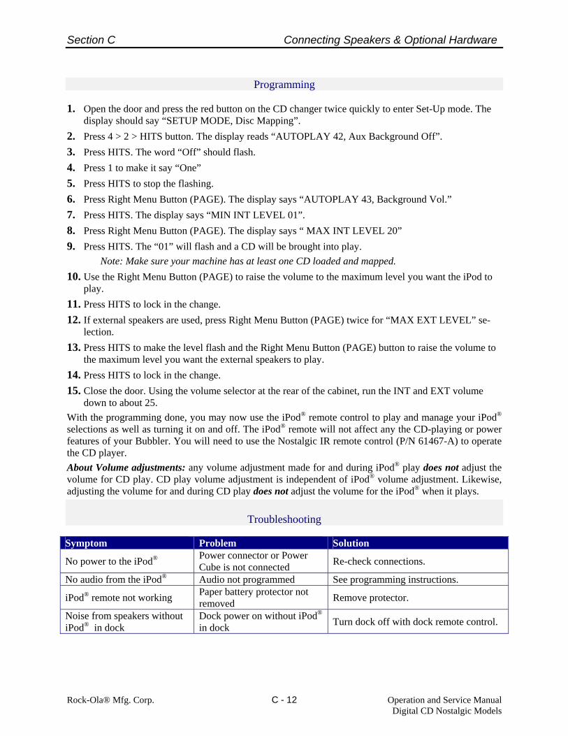
1. Open the door and press the red button on the CD changer twice quickly to enter Set-Up mode. The
display should say “SETUP MODE, Disc Mapping”. 2. Press 4 > 2 > HITS button. The display reads “AUTOPLAY 42, Aux Background Off”. 3. Press HITS. The word “Off” should flash. 4. Press 1 to make it say “One” 5. Press HITS to stop the flashing. 6. Press Right Menu Button (PAGE). The display says “AUTOPLAY 43, Background Vol.” 7. Press HITS. The display says “MIN INT LEVEL 01”. 8. Press Right Menu Button (PAGE). The display says “ MAX INT LEVEL 20” 9. Press HITS. The “01” will flash and a CD will be brought into play. Note: Make sure your machine has at least one CD loaded and mapped. 10. Use the Right Menu Button (PAGE) to raise the volume to the maximum level you want the iPod to
play. 11. Press HITS to lock in the change. 12. If external speakers are used, press Right Menu Button (PAGE) twice for “MAX EXT LEVEL” se-
lection. 13. Press HITS to make the level flash and the Right Menu Button (PAGE) button to raise the volume to
the maximum level you want the external speakers to play. 14. Press HITS to lock in the change. 15. Close the door. Using the volume selector at the rear of the cabinet, run the INT and EXT volume
down to about 25. With the programming done, you may now use the iPod® remote control to play and manage your iPod® selections as well as turning it on and off. The iPod® remote will not affect any the CD-playing or power features of your Bubbler. You will need to use the Nostalgic IR remote control (P/N 61467-A) to operate the CD player. About Volume adjustments: any volume adjustment made for and during iPod® play does not adjust the volume for CD play. CD play volume adjustment is independent of iPod® volume adjustment. Likewise, adjusting the volume for and during CD play does not adjust the volume for the iPod® when it plays.
Troubleshooting
Symptom Problem Solution
No power to the iPod® Power connector or Power Cube is not connected Re-check connections.
No audio from the iPod® Audio not programmed See programming instructions.
iPod® remote not working Paper battery protector not removed Remove protector.
Noise from speakers without iPod® in dock
Dock power on without iPod®
in dock Turn dock off with dock remote control.

Section
D
Amplifier Description and Operation
- Amplifier Description- Indicator LED’s- Signal Inputs & Outputs- Amplifier Feature Description- Setting the Amplifier
D - 1

Section D Amplifier Description and Operation
Rock-Ola Mfg. Corp. Operation and Service Manual Digital CD Nostalgic Models
D - 2
Figure 1D – Digital SyberSonic Dual Amplifier
Amplifier Description Rock-Ola’s Dual Digital SyberSonic Amplifier has been engineered for ease of connection and has options to meet virtually any location requirement. With audio efficiencies approaching 95%, this system produces volume levels equal to an am-plifier twice its size and does so without produc-ing a great amount of heat. The system consists of a dual stereo (4 channel) pre-amplifier combined with two 2-channel power amplifiers. The system may be operated as a single zone or a dual zone stereo system with separate volume controls for each zone. The amplifier sends its power to an audio output panel that couples speaker loads of ½ to 4 Ohms. If greater flexibility in speaker loads is needed or if the location is using 70-Volt CV speakers, an optional audio distribution assembly (P/N 70046-1A) may be installed. Please Note: This section mentions Internal and External Amplifiers. “Internal” refers to the two channels controlled by the “INT” vol-ume buttons and normally connected to the jukebox speakers. “External” refers to the 2 channels controlled by the “EXT” volume but-tons used for external.
Specifications and Operating Features • System is rated 900 Watts of peak music power at
4 Ohms. With audio efficiencies approaching 95%, this system produces volume levels equal to an amplifier twice its size and does so without produc-ing a great amount of heat.
• Switchable Stereo/Mono Modes • Separate 7 band equalizers for all four channels. • 7 Band equalizer may be split for separate left and
right channel settings. • Loudness Contour control. Setting is split to pro-
vide separate Left and Right channel control. • Left to Right Balance Control. • Multiple volume control configurations. • Built in Paging System input. • Switch setting for microphone gain. Dial control for
maximum microphone volume. • Music Level While Paging settings. Settings are
split to provide separate Left and Right channel control.
• “Always On” amplifier for special event audio and
background music functions. (Only if phono is turned off with I.R. Remote Volume Control.)
• Automatic Volume Control. (AVC)
Section D Amplifier Description and Operation
Rock-Ola Mfg. Corp. Operation and Service Manual Digital CD Nostalgic Models
D - 3
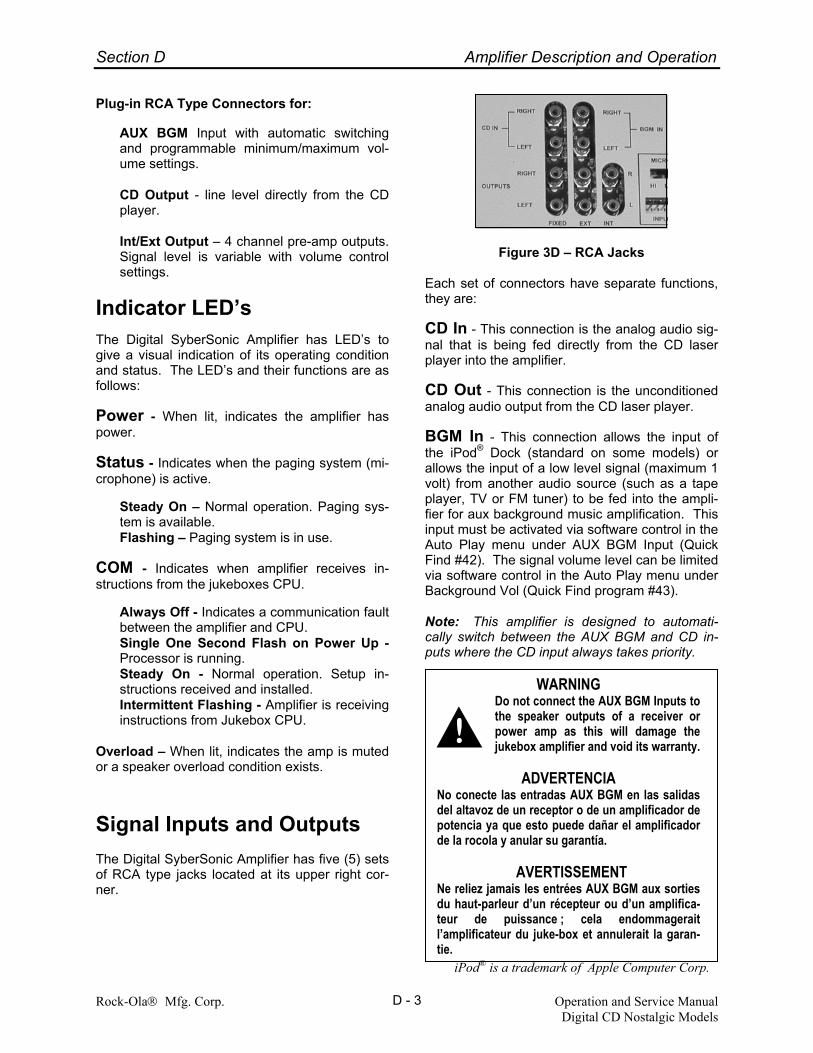
Plug-in RCA Type Connectors for:
AUX BGM Input with automatic switching and programmable minimum/maximum vol-ume settings. CD Output - line level directly from the CD player. Int/Ext Output – 4 channel pre-amp outputs. Signal level is variable with volume control settings.
Indicator LED’s The Digital SyberSonic Amplifier has LED’s to give a visual indication of its operating condition and status. The LED’s and their functions are as follows: Power - When lit, indicates the amplifier has power. Status - Indicates when the paging system (mi-crophone) is active.
Steady On – Normal operation. Paging sys-tem is available. Flashing – Paging system is in use.
COM - Indicates when amplifier receives in-structions from the jukeboxes CPU.
Always Off - Indicates a communication fault between the amplifier and CPU. Single One Second Flash on Power Up - Processor is running. Steady On - Normal operation. Setup in-structions received and installed. Intermittent Flashing - Amplifier is receiving instructions from Jukebox CPU.
Overload – When lit, indicates the amp is muted or a speaker overload condition exists.
Signal Inputs and Outputs The Digital SyberSonic Amplifier has five (5) sets of RCA type jacks located at its upper right cor-ner.
Figure 3D – RCA Jacks
Each set of connectors have separate functions, they are:
CD In - This connection is the analog audio sig-nal that is being fed directly from the CD laser player into the amplifier.
CD Out - This connection is the unconditioned analog audio output from the CD laser player.
BGM In - This connection allows the input of the iPod® Dock (standard on some models) or allows the input of a low level signal (maximum 1 volt) from another audio source (such as a tape player, TV or FM tuner) to be fed into the ampli-fier for aux background music amplification. This input must be activated via software control in the Auto Play menu under AUX BGM Input (Quick Find #42). The signal volume level can be limited via software control in the Auto Play menu under Background Vol (Quick Find program #43). Note: This amplifier is designed to automati-cally switch between the AUX BGM and CD in-puts where the CD input always takes priority.
WARNING Do not connect the AUX BGM Inputs to the speaker outputs of a receiver or power amp as this will damage the jukebox amplifier and void its warranty.
ADVERTENCIA
No conecte las entradas AUX BGM en las salidas del altavoz de un receptor o de un amplificador de potencia ya que esto puede dañar el amplificador de la rocola y anular su garantía.
AVERTISSEMENT Ne reliez jamais les entrées AUX BGM aux sorties du haut-parleur d’un récepteur ou d’un amplifica-teur de puissance ; cela endommagerait l’amplificateur du juke-box et annulerait la garan-tie.
iPod® is a trademark of Apple Computer Corp.
Section D Amplifier Description and Operation
Rock-Ola Mfg. Corp. Operation and Service Manual Digital CD Nostalgic Models
D - 4
Int Out - This connection is a variable level out-put signal directly from the internal pre-amp. The signal level follows the internal volume control. Output signal may be limited via software control in the Set-up 1 menu under the Volume Range (Quick Find program #78). Ext Out - This connection is a variable level output signal directly from the external pre-amp. The signal level follows the external volume con-trol. Output signal may be limited via software control in the Set-up 1 menu under the Volume Range (Quick Find program #78).
Amplifier Feature Descrip-tions Your Digital SyberSonic Amplifier is preset at the factory for optimum operation, however some adjustment may be required to achieve the best sound or operating features for your particular environment. For ease of use, amplifier features are set/adjusted via the jukeboxes keyboard. Instructions are found in the section titled “Setting The Amplifier” later in this chapter. AVC Control - The Digital SyberSonic Ampli-fier uses software to limit the difference between loud and soft recordings (dynamic range). Auto-matic Volume Control (AVC) will retain the dy-namic range of the recording, just reduce it. The effect is that the music sounds natural but songs with loud passages are only slightly louder. AVC also controls the BGM IN signal. Note: This fea-ture is on all the time and cannot be defeated. Equalizer - This changes speaker tone by de-creasing the response (gain) of a particular fre-quency range. The internal and external amplifi-ers have separate settings. Balance - This setting allows you to adjust the left to right balance of the speakers. Set the bal-ance for internal and external amplifiers sepa-rately. Music Level While Paging (MLWP) - This setting changes how much of the music is heard when using a microphone for paging while music is playing. The internal and external amplifiers have separate settings. The music level is a per-centage of the current volume. Choices are 0% to 100% in increments of 10% and Off where Off defeats paging for that channel.
Page Decay – Sets the amount of time in sec-onds before the music resumes its normal vol-ume after a page. The range is from 2 seconds to 10 seconds. Loudness Contour - This setting allows you to turn on or off the loudness contour enhance-ment for the internal and external amplifiers sepa-rately. The Loudness Contour enhances bass output at lower volume levels. Reset Internal/External Amp - This pro-vides for rapid resetting of the amplifier features to their factory settings. The factory settings are as follows: Equalizer - +5, +5, +4, +3, +4, +5, +5 Balance - Centered MLWP - 50% Loudness - On The internal and external amplifiers are reset separately. Volume Limits - The Digital SyberSonic am-plifiers can have their volumes set to minimum and maximum levels. The internal and external amplifiers are set separately in both Normal Play and Background Music Modes. Additionally, each amplifiers maximum volume may be limited based on day of week and time of day. Volume Bridging – There may be times when you do not want a location to have separate control of the internal and external amplifier. Or perhaps you want two areas to have separate volume controls. SyberSonic’s advanced elec-tronics system allows the “bridging” of its volume controls. When bridged, the tied ampli-fier/channel’s volume will change regardless of which volume control button is pushed. Specific bridging information is in the “Setting the Ampli-fier” section.
Setting The Amplifier The graphic equalizer, balance, and other fea-tures are adjusted via the jukebox keyboard with settings represented by a graphic shown on the keyboard display. To set the amplifier features, access the SETUP MODE by ensuring the service switch is in its center position then “double click” the Red Scan/Cancel But-ton. Once in the Setup Mode, “program the amp” via the jukebox keyboard in the same way that all other programming is done. Section E of this manual con-

Section D Amplifier Description and Operation
Rock-Ola Mfg. Corp. Operation and Service Manual Digital CD Nostalgic Models
D - 5
tains specific instructions for accessing and using the SETUP MODE. Section E also contains “flow charts” which give a graphical representation of the SETUP MODE functions. The following section will only give the Quick Find programming number and what to ex-pect when changing/adjusting features. Settings common to both the Internal and External Amps Automatic Volume Control (AVC) - AVC is controlled in software. To change, from the setup mode, access quick find 231, then press Hits. Display will show: Press Hits to make the current setting flash. Press #1 until the desired setting is displayed. Press Hits to lock in your choice when finished press Reset several times. Page Decay – To change, from the Setup Mode, access Quick Find 212 then press hits. Display will show: Press HITS to make the current setting flash then enter the number of decay seconds from 2 to 10. Once the desired time has been entered, press HITS to lock it in. Display will show: When finished, press the RESET button several times. Internal Amp Settings Internal Equalizer – Sets the internal amplifier 7 band graphic equalizer. (HINT: To hear the tone setting changes, play a song and set the volume before entering the Setup Mode.) Setting 7 Band Equalizer – You may set the left and right channels simultaneously or each chan-nel may be set individually.
EQ Join sets both channels. EQ L/R allows you to set the Left and Right channels separately. To set the equalizer, from the Setup Mode access Quick Find 213 then press HITS. The display will show: Press HITS to make ”current setting” flash then press the #1 button to choose from EQ L/R or EQ Join. Press HITS to lock in your choice. Display will show: If EQ Join is chosen the display will show: To change settings, press the HITS Button. The display will show a graphical representation of the current settings similar to the figure below.
Use the left or right Turn Pages button to move the asterisk to the desired frequency. Press the #1 key to raise the gain and the #2 key to lower it. The amplifier will respond to any changes in-stantly. If EQ L/R is chosen the display will show: To change the Left channel, press HITS and set the same as in the EQ Join instructions above. Press Reset once when finished. To change the Right channel, press the Right Turn Pages button so the display shows:
AMP SETUP 213 Int Tone current setting
AMP SETUP 213 Int Tone EQ your choice
AMP SETUP 213 Internal EQ
AMP SETUP 213 Int Left EQ
AMP SETUP 213 Int Right EQ
AMP SETUP 212 Page Decay current setting
AMP SETUP 212 Page Decay new setting
*
AMP SETUP 231 AVC current setting

Section D Amplifier Description and Operation
Rock-Ola Mfg. Corp. Operation and Service Manual Digital CD Nostalgic Models
D - 6
Press the HITS button and set the same as in the EQ Join instructions above. When finished, press the RESET button several times. Internal Balance - Access Quick Find 214 to view/change the balance for speakers connected to the internal amplifier. Use the left and right menu keys to change the balance. NOTE: If Vol-ume Control Bridging (QF 79) is set to Split, the balance control is defeated. When finished, press the RESET button several times.
Internal Music Level While Page (MLWP) – The left and right channels are set separately. Choices are 0% (music completely muted) to 100% (no muting) in increments of 10% and Off. (no paging for that channel) For left channel, from the Setup Mode, access Quick Find 218 then press HITS. Display will show: Press HITS to make the current setting flash then press #1 until the desired setting is displayed. Press HITS to lock in your choice. When finished, press the RESET button several times. For Right channel, from the Setup Mode, access Quick Find 219 then press HITS. Display will show: Press HITS to make the current setting flash then press #1 until the desired setting is displayed. Press HITS to lock in your choice. When finished, press the RESET button several times. Internal Loudness – Left and Right chan-nels are set separately. For Left channel, from the Setup Mode, access Quick Find 220 then press HITS. Display will show:
Press HITS to make the current setting flash then press #1 until the desired setting is displayed. Press HITS to lock in your choice. When finished, press the RESET button several times. For Right channel, from the Setup Mode, access Quick Find 221 then press HITS. Display will show: Press HITS to make the current setting flash then press #1 until the desired setting is displayed. Press HITS to lock in your choice. When finished, press the RESET button several times.
Reset Internal Amp - Access Quick Find 217 and press Hits twice to restore the internal amplifier to its factory settings. Once completed, press the RESET button several times.
External Amp Settings The External Amp (Auxiliary Amp) is set the same as the Internal Amp, therefore only the Quick Find numbers will be shown here. To set the External Amp, follow the Internal Amp instruc-tions and substitute the appropriate Quick Find number. External Equalizer - Access Quick Find 222 to view/change the equalizer/tone settings for the external amplifier. External Balance - Access Quick Find 223 to view/change the balance for speakers con-nected to the external amplifier. External Music Level While Page (MLWP) - Access Quick Find 227 for the Left channel or 228 for the Right channel and toggle to the desired setting.
External Loudness - Access Quick Find 229 for the Left channel or Quick Find 230 for the Right channel then toggle to Off or On. Reset External Amplifier - Access Quick Find 226 and press Hits twice to restore the ex-ternal amplifier to its factory settings. External AVC – Access Quick Find 232 to turn the external AVC on or off.
AMP SETUP 218 Int LTMLWP current setting
AMP SETUP 219 Int RT MLWPcurrent setting
AMP SETUP 220 Int Lt Loud current setting
AMP SETUP 221 Int Rt Loud current setting

Section D Amplifier Description and Operation
Rock-Ola Mfg. Corp. Operation and Service Manual Digital CD Nostalgic Models
D - 7
Other Settings Volume Control Options - Choices are Normal, Split and Bridge. Normal – The internal buttons control the stan-dard amp and the external buttons control the optional auxiliary amplifier. To set, from the Setup Mode, access Quick Find 79 and press HITS. Display will show: Press HITS. “Current Setting” will flash. Press #1 until “Normal” is displayed. Press HITS to lock in the setting. Once finished, press RESET several times. Volume Split – If selected, the internal buttons control the left channel and the external buttons control the right channel.
WARNING This feature cannot be used if the ex-ternal amplifier is installed or if the external output jacks are used. The
auxiliary amplifier and external output signals will not function.
ADVERTENCIA Esta característica no se puede usar si el amplifi-cador externo está instalado o si se están usando los jacks de salida externa. El amplificador auxi-liar y las señales de salida externa no funcion-arán.
AVERTISSEMENT Si l’amplificateur externe est installé ou si les pri-ses de sortie externes sont utilisées, vous ne pourrez accéder à cette fonctionnalité. L’amplificateur auxiliaire ne fonctionnera pas ; aucun signal de sortie ne pourra être transmis.
To set, from the Setup Mode, access Quick Find 79 and press HITS. Display will show:
Press HITS. “Current Setting” will flash. Press #1 until “Split” is displayed. Press HITS to lock in the setting. Once finished, press RESET several times. Volume Bridge – When bridged, the tied ampli-fier/channel’s volume will change regardless of which volume control button is pushed. Volume Bridge Options are:
Bridge Int - Ext B. Ties both the right and left external amplifier channels to the internal amplifier volume control. Nor-mally used in installations where the jukebox and external speakers are lo-cated in the same room. In this mode pushing either set of volume buttons will control the internal and ex-ternal volume at the same time. Bridge Int - Ext R. Ties the right exter-nal amplifier channel to the internal am-plifier volume control. Normally used in an installation where the jukebox and an external speaker(s) are in one room with another external speaker(s) installed in another room or area.
In this mode pushing an internal volume button will change the volume for the jukebox and the external speaker(s) con-nected to the right external channel. Pushing an external volume button will change the volume for a speaker(s) con-nected to the left external channel that is another area or room. Bridge Int - Ext L. Same as above ex-cept the channels are reversed.
Note: If an individual external channel is bridged to the internal amp, the external balance control is disabled. Before setting the volume bridge you must first “balance” the internal and external speakers. To do so, simply play a song and set the Internal and External volumes to the desired levels. Once the desired balance has been achieved, access the setup mode by ensuring the service switch is in its center position then “double click” the Red Scan/Cancel button.
SET-UP 1 79 Volume Current Setting
SET-UP 1 79 Volume Normal
SET-UP 1 79 Volume Current Setting
SET-UP 1 79 Volume Split

Section D Amplifier Description and Operation
Rock-Ola Mfg. Corp. Operation and Service Manual Digital CD Nostalgic Models
D - 8
To set, from the Setup Mode, access Quick Find 79 and press HITS. Display will show: Press HITS. “Current Setting” will flash. Press #1 until “Bridged” is displayed. Press HITS to lock in the setting. Display will show: Press HITS to make “Ext Current Setting” flash then press #1 until the desired bridge option is displayed. Press HITS to lock it in. Display will show: Once finished, press RESET several times. Volume Limits - Sets the minimum and maximum allowable volume for the internal and external amplifiers separately. A timed option is also available to limit the maximum volume dur-ing certain hours. Note: Background Music Vol-ume limits are set in the Autoplay menu, Quick Find 43. The volume limits cannot be set if Volume Control Option (Quick Find 79) is set to Split or Bridge. If the use of volume control splitting or bridging is desired, adjust the volume limits first, then set volume control option to the desired setting. When setting volume limits, the jukebox will automatically pick up CD number 00 and play its first track so that you can hear the volume level. Internal Amp System Min/Max limits, from the Setup Mode, access Quick Find 78 and press HITS. Display will show: Press the HITS button. “Current Setting” will flash. Press the #1 button until display shows “Volume Range On” then press the HITS button. Display will show:
Press the HITS button again and the display will show: Press the HITS button and the display will show: Press HITS to make “Current Setting” flash then use the right Turn Pages button to increase the volume. (Range is 0-40) Once the desired level is reached, press HITS to lock it in. Display will show: Press the right Turn Pages button. Display will show: Press HITS to make “Current Setting” flash then use the right Turn Pages button to increase the volume. (Range is 0-40) Once the desired level is reached, press HITS to lock it in. Display will show: When finished, press RESET several times. External System Min/Max limits, from the Setup Mode, access Quick Find 78 and press HITS. Display will show: Press the HITS button. “Current Setting” will flash. Press the #1 button until display shows “Volume Range On” then press the HITS button. Display will show:
SET-UP 1 79 Volume Current Setting
SET-UP 1 79 Bridge Int – Ext Current Setting
SET-UP 1 79 Bridge Int – Ext Desired Setting
SET-UP 1 78 Internal Limits
SET-UP 1 78 System Min/Max
SET-UP 1 78 Min Vol Current Setting
SET-UP 1 78 Max Vol Desired Setting
SET-UP 1 78 Internal Limits
SET-UP 1 78 Volume Range Current Setting
SET-UP 1 78 Max Vol Current Setting
SET-UP 1 78 Volume Range Current Setting
SET-UP 1 78 Max Vol Desired Setting
Section D Amplifier Description and Operation
Rock-Ola Mfg. Corp. Operation and Service Manual Digital CD Nostalgic Models
D - 9
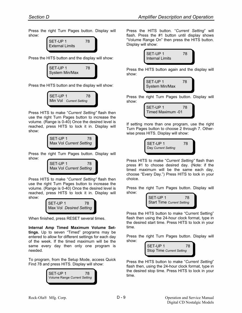
Press the right Turn Pages button. Display will show: Press the HITS button and the display will show: Press the HITS button and the display will show: Press HITS to make “Current Setting” flash then use the right Turn Pages button to increase the volume. (Range is 0-40) Once the desired level is reached, press HITS to lock it in. Display will show: Press the right Turn Pages button. Display will show: Press HITS to make “Current Setting” flash then use the right Turn Pages button to increase the volume. (Range is 0-40) Once the desired level is reached, press HITS to lock it in. Display will show: When finished, press RESET several times. Internal Amp Timed Maximum Volume Set-tings. Up to seven “Timed” programs may be entered to allow for different settings for each day of the week. If the timed maximum will be the same every day then only one program is needed. To program, from the Setup Mode, access Quick Find 78 and press HITS. Display will show:
Press the HITS button. “Current Setting” will flash. Press the #1 button until display shows “Volume Range On” then press the HITS button. Display will show: Press the HITS button again and the display will show: Press the right Turn Pages button. Display will show: If setting more than one program, use the right Turn Pages button to choose 2 through 7. Other-wise press HITS. Display will show: Press HITS to make “Current Setting” flash than press #1 to choose desired day. (Note: if the timed maximum will be the same each day, choose “Every Day.”) Press HITS to lock in your choice. Press the right Turn Pages button. Display will show: Press the HITS button to make “Current Setting” flash then using the 24-hour clock format, type in the desired start time. Press HITS to lock in your time. Press the right Turn Pages button. Display will show: Press the HITS button to make “Current Setting” flash then, using the 24-hour clock format, type in the desired stop time. Press HITS to lock in your time.
SET-UP 1 78 System Min/Max
SET-UP 1 78 Min Vol Current Setting
SET-UP 1 78 Max Vol Current Setting
SET-UP 1 78 Max Vol Desired Setting
SET-UP 1 78 External Limits
SET-UP 1 78 Internal Limits
SET-UP 1 78 Volume Range Current Setting
SET-UP 1 78 System Min/Max
SET-UP 1 78 Timed Maximum -01
SET-UP 1 78 Day Current Setting
SET-UP 1 78 Start Time Current Setting
SET-UP 1 78 Max Vol Current Setting
SET-UP 1 78 Stop Time Current Setting

Section D Amplifier Description and Operation
Rock-Ola Mfg. Corp. Operation and Service Manual Digital CD Nostalgic Models
D - 10
Press the right Turn Pages button. Display will show: Press HITS button to make “Current Setting” flash then type in the Maximum allowable volume level. Press HITS to lock in the setting. When finished, press RESET several times. External Timed Maximum Volume Settings. Up to seven “Timed” programs may be entered to allow for different settings for each day of the week. If the timed maximum will be the same every day then only one program is needed. To program, from the Setup Mode, access Quick Find 78 and press HITS. Display will show: Press the HITS button. “Current Setting” will flash. Press the #1 button until display shows “Volume Range On” then press the HITS button. Display will show: Press the right Turn Pages button. Display will show: Press the right Turn Pages button. Display will show: If setting more than one program, use the right Turn Pages button to choose 2 through 7. Other-wise press HITS. Display will show: Press HITS to make “Current Setting” flash than press #1 to choose desired day. (Note: if the timed maximum will be the same each day, choose “Every Day.”) Press HITS to lock in your choice.
Press the right Turn Pages button. Display will show: Press the HITS button to make “Current Setting” flash then using the 24-hour clock format, type in the desired start time. Press HITS to lock in your time. Press the right Turn Pages button. Display will show: Press the HITS button to make “Current Setting” flash then, using the 24-hour clock format, type in the desired stop time. Press HITS to lock in your time. Press the right Turn Pages button. Display will show: Press HITS button to make “Current Setting” flash then type in the Maximum allowable volume level. Press HITS to lock in the setting. When finished, press RESET several times.
SET-UP 1 78 Timed Max Current Setting
SET-UP 1 78 Internal Limits
SET-UP 1 78 Volume Range Current Setting
SET-UP 1 78 Start Time Current Setting
SET-UP 1 78 Timed Max Current Setting
SET-UP 1 78 External Limits
SET-UP 1 78 Timed Maximum -01
SET-UP 1 78 Day Current Setting
SET-UP 1 78 Stop Time Current Setting

Section
E
Operation and ProgrammingOverview
- Normal Operation- Control Computer Buttons- Programming, Service and Diagnostics Feature Overview- Quick Find Reference Programming Definitions- Quick Find Reference Programming Flow Charts
E - 1

Section E Operation and Programming
Rock-Ola® Mfg. Corp. Operation and Service Manual Digital CD Nostalgic Models
E - 2
Normal Operation (Play Mode) The following messages will appear while the jukebox is in the Normal Operation mode. Dis-played messages will differ depending upon which features have been selected in the Setup Mode.
Attract State - no credits in the jukebox, or after 2 minutes of no keyboard activity.
• The top line is stationary.
• The bottom line scrolls.
• Each message will stay on the display until the bottom message scrolls to completion.
• The display will blank between each mes-sage for a short time.
Example Message:
Current Attract Messages - No credits on ma-chine.
• Line 1 - toggles between “Rock-Ola Juke-box” and “100 Disc Changer” (if surround sound is OFF), else
• Line 1 - toggles between “Rock-Ola Juke-box” and “Enhanced Stereo” (if surround sound is ON).
If HITS button (Quick Find 45) is programmed to View, display will read:
• Line 1 - Rock-Ola Jukebox…
Line 2 - Press the HITS button to view each top hit.
If Hits button (Quick Find 45) is programmed to Play, display will read:
• Line 1 - Rock-Ola Jukebox…
Line 2 - Press the HITS button to play each top hit.
• Line 1 - Rock-Ola Jukebox… Line 2 - To add credits insert bills or coins.
• Line 1 - Rock-Ola Jukebox…
Line 2 - Press page buttons to view albums.
If Free Play is active, display will read:
• Line 1 - Rock-Ola Jukebox… Line 2 - All selections are currently free
Customer started making selection via keyboard
• Line 1 - Your choice - - - Line 2 - Credits: Free
Credits State - customer put money in the jukebox.
• Not yet enough money for a credit.
• Credits in jukebox.
• Customer has pressed the Hits key and Hits Button (Quick Find 45) is programmed to View.
• Customer has pressed the Hits button with Hits Button (Quick Find 45) programmed to automatically play the top hits.
• Customer has started making a normal se-lection via keyboard
• Customer has started pressing the number keys on the deluxe remote.
Rock-Ola Jukebox Press the Hits button…
Insert Money Credits: 0
Make Selection Credits: 3
Top Hit #01 0305 Credits: 3
Your Choice 01-- Credits: 3
Remote Sel. 36-- Credits: 3
Your Choice 0305 Credits: 2

Section E Operation and Programming
Rock-Ola® Mfg. Corp. Operation and Service Manual Digital CD Nostalgic Models
E - 3
• Customer has pressed the Programmed Play button on the remote.
• ## Not Available (scrolls the message).
• #### Not Available (scrolls the message).
• Album Selection Not Available (scrolls the message).
• Selection #### Requires ## Credits (scrolls the message).
• Remote Selection Not Available (scrolls the message).
• Once the mechanism loads a disc onto the CD player and music is heard, the display will readout:
And messages will scroll by on the bottom line.
Figure 1E - SyberSonic Control Computer
Once the dome is open and the service mode is entered, the three (3) buttons on the top of the control computer become active. (To enter Service Mode, see explanation later in this section.) The 3 buttons are:
Diagnostics - This button puts the system into self-diagnostic mode that tests the control computer, CD player communications and keyboard / display assembly communication.
Setup - This buttons puts the system into programming set-up mode at the top of the menu hierarchy and also allows direct access to programs via program’s quick find numbers.
Resume – This button returns the system to the service mode from the setup mode.
01 Not Avai Credits: 3
#### Not Avai Credits: 3
Album Selection… Credits: 3
Selection 0206 R Credits: 3
Remote Selection… Credits: 3
Now Playing 0305 Credits: 3
Program Play: - Enter List (1-3)

Section E Operation and Programming
Rock-Ola® Mfg. Corp. Operation and Service Manual Digital CD Nostalgic Models
E - 4
Programming, Service and Diagnostic Features This section is intended to familiarize you with the service, programming and diagnostic fea-tures of the SyberSonic Electronics System. Specific programming and operating instructions will be covered in later sections.
Suspend Mode For safety, Rock-Ola’s SyberSonic System (Software Version 3.6 and above) incorporates an automatic mechanism interlock system.
Whenever the Dome/Lid is opened the mecha-nism will enter a “suspend mode” and the ma-chine’s display will indicate: “DOOR OPEN” on the top line and the bottom line will scroll the message: “Press Scan Switch to Continue. Warning: Mechanism Could Start Anytime.”
If a song is playing when the machine is opened, that song will finish and the mechanism will stop. The only exception is if the next song in the play queue is on the same disc. In that case the next song will play.
Service and Setup Mode The service and setup modes are where all of the service functions, auditing and programming take place.
Service Mode The service mode is entered into by opening the dome/door and pressing the Scan/Cancel But-ton on playing mechanism one time. (If the dome/door is already opened, note the service switch is in its middle position.)
Figure 3E - Service Switch
Note: If the jukebox has a TeleCommunications module installed and the Break-In Notification feature (Quick Find 172) is activated, the Setup Mode must be accessed and the correct pass-word must be entered within 30 seconds of opening the lid/door. Failure to do so will result
in the automatic sending of a break-in warning. The system will wait 30 seconds after being in the normal mode before rearming the Break-In feature.
The red scan/cancel switch on the mechanism only works when the service switch is in the ser-vice position (middle). If the service switch is in the “normal operate” position, the scan/cancel switch will add credits to the jukebox.
When the dome/door is opened, the service switch automatically moves to its middle po-sition. The top line of the display will indicate that the machine is in the Service Mode.
The bottom line indicates that the service mode is active. This means the system is ready for further programming and/or diagnostic functions.
If songs are in queue and playing, they will con-tinue to play.
In this mode the operator can insert money or make selections without affecting the audit to-tals. Used for testing bill and coin acceptors.
Note: Any money inserted while in Service Mode is not included in the accounting data. Any songs selected while in the service mode will take priority over any songs that may be in the selection memory.
Note: Any selections made while in the service mode will not affect the popularity figures.
To rotate magazine press the scan/cancel but-ton. Pressing the scan/cancel button while in the service mode will cause the display to change to:
The displayed number indicates which slot is positioned under the CD gripper bow. If a selec-tion is playing, it will be canceled. Pressing the scan/cancel once will advance the magazine to the next slot and update the display. Pressing and holding the button will spin the magazine and update the display. When the scan/cancel button is released, the magazine will stop with a
SERVICE MODE Service Mode is Active
DOOR OPEN Press Scan Switch to …
SERVICE MODE At Slot 00
Section E Operation and Programming
Rock-Ola® Mfg. Corp. Operation and Service Manual Digital CD Nostalgic Models
E - 5
slot directly under the gripper bow and display that slot number. Setup Mode All auditing, programming and most testing is done from this mode. To enter the Setup Mode, make sure the jukebox is in the Service Mode then push the SETUP button on the SyberSonic Computer (Fig. 1E).
The Setup Mode may be accessed by “Dou-ble Clicking” the Scan/Cancel Switch when the dome is first opened.
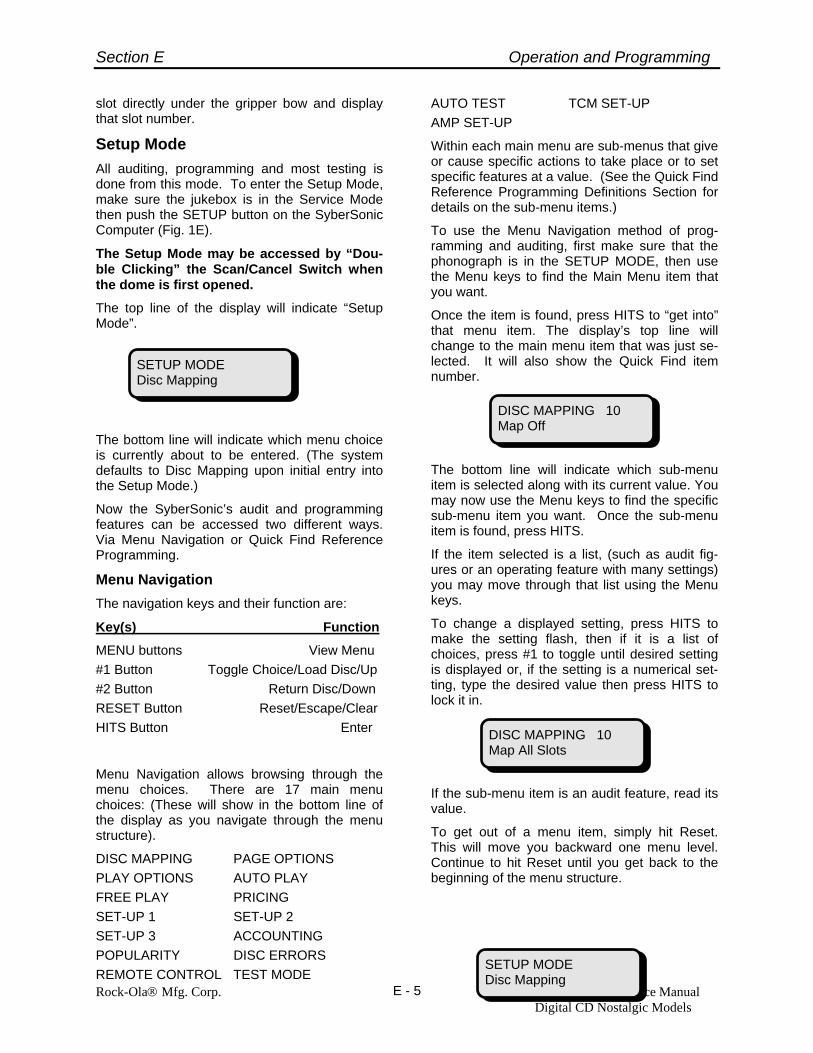
The top line of the display will indicate “Setup Mode”.
The bottom line will indicate which menu choice is currently about to be entered. (The system defaults to Disc Mapping upon initial entry into the Setup Mode.)
Now the SyberSonic’s audit and programming features can be accessed two different ways. Via Menu Navigation or Quick Find Reference Programming.
Menu Navigation The navigation keys and their function are:
Key(s) Function
MENU buttons View Menu #1 Button Toggle Choice/Load Disc/Up #2 Button Return Disc/Down RESET Button Reset/Escape/Clear HITS Button Enter
Menu Navigation allows browsing through the menu choices. There are 17 main menu choices: (These will show in the bottom line of the display as you navigate through the menu structure).
DISC MAPPING PAGE OPTIONS PLAY OPTIONS AUTO PLAY FREE PLAY PRICING SET-UP 1 SET-UP 2 SET-UP 3 ACCOUNTING POPULARITY DISC ERRORS REMOTE CONTROL TEST MODE
AUTO TEST TCM SET-UP AMP SET-UP
Within each main menu are sub-menus that give or cause specific actions to take place or to set specific features at a value. (See the Quick Find Reference Programming Definitions Section for details on the sub-menu items.)
To use the Menu Navigation method of prog-ramming and auditing, first make sure that the phonograph is in the SETUP MODE, then use the Menu keys to find the Main Menu item that you want.
Once the item is found, press HITS to “get into” that menu item. The display’s top line will change to the main menu item that was just se-lected. It will also show the Quick Find item number.
The bottom line will indicate which sub-menu item is selected along with its current value. You may now use the Menu keys to find the specific sub-menu item you want. Once the sub-menu item is found, press HITS.
If the item selected is a list, (such as audit fig-ures or an operating feature with many settings) you may move through that list using the Menu keys.
To change a displayed setting, press HITS to make the setting flash, then if it is a list of choices, press #1 to toggle until desired setting is displayed or, if the setting is a numerical set-ting, type the desired value then press HITS to lock it in.
If the sub-menu item is an audit feature, read its value.
To get out of a menu item, simply hit Reset. This will move you backward one menu level. Continue to hit Reset until you get back to the beginning of the menu structure.
DISC MAPPING 10 Map Off
DISC MAPPING 10 Map All Slots
SETUP MODE Disc Mapping
SETUP MODE Disc Mapping

Section E Operation and Programming
Rock-Ola® Mfg. Corp. Operation and Service Manual Digital CD Nostalgic Models
E - 6
To exit the Service or Setup Mode, simply close the dome/door.
Quick Find Reference Programming This method provides direct access to a specific operating feature or audit capability. To use it, get into the SETUP MODE and type in the Quick Find number for the item you want then press HITS.
The display will change to the selected prog-ramming feature.
Navigation within and getting out of the item is the same as in Menu Navigation.
Diagnostic and Error Reporting Features The SyberSonic’s microprocessor technology allows it to “keep track” of itself. It senses when it does something wrong or when something abnormal happens, then stores that information in its memory to report it to you when you ask for it. In fact, the SyberSonic Jukebox automatically warns you if an error has occurred whenever the Service Mode is entered into by displaying:
“XXXX” indicating whichever area has errors.
Disc Errors The SyberSonic system keeps track of playing errors and reports the disc and track numbers as well as how many times the error has oc-curred. If an individual disc or track exceeds the
preprogrammed number of allowable errors, the jukebox automatically locks the track or disc out. Disc Error Quick Find numbers are 110 through 115.
Hardware Errors Every Rock-Ola Jukebox is constantly monitored by its SyberSonic Electronics system. The sys-tem is always looking at its inputs and outputs to insure that everything is working correctly. Should a malfunction occur, the computer logs an error code, along with the date and time of the malfunction. A service technician can use this information to quickly diagnose and repair any problem. The error codes are stored in the Test Mode menu. (Quick Find items 136 through 140).
Test Mode All Rock-Ola SyberSonic Jukeboxes have easy to use “self tests” built in. These tests provide a means to test the electronics and mechanics of the machine. They also provide useful trouble-shooting and adjustment tools. Also provided is a test for the laser player. (Another of the many Rock-Ola exclusives.) This feature takes the guesswork out of diagnosing a player malfunc-tion while on location. The self-tests are found in the Test Mode menu. (Quick Find 131 through 134 and 142 through 149).
Auto Test This feature is used at the factory for “burning in” every jukebox we produce. It automatically runs the SyberSonic System through the Mech, Keyboard, Pages and Display tests. The Auto Test feature is also useful to test the machine for bad discs before installing the SyberSonic Juke-box on location. For more information, see the Quick Find Reference Definitions section for Quick Find 150 through Quick Find 160.
Diagnostics Mode - Tests the control com-puter, CD player communications & Keyboard Assembly.
Diagnostics Mode is entered by pressing the Diag Button on the front of the control computer while in the Service Mode. Tests are automati-cally performed and status messages are dis-played. (See Diagnostic Mode Operation in the Troubleshooting and Repair section H for more details.)
SERVICE MODE Errors Present in: XXXX
SETUP MODE Quick Find: 12
DISC MAPPING 12 Disc Lockouts

Section E Operation and Programming
Rock-Ola® Mfg. Corp. Operation and Service Manual Digital CD Nostalgic Models
E - 7
Rock-Ola Quick Find Reference Programming To program, open front door then “double click” red button. From the SETUP MODE enter the 2 or 3 digit number and push the HITS button. To change settings, press HITS to make setting flash then Toggle choices with #1 and #2 or enter numeric value. Press HITS to lock in setting. Use left and right “Turn Pages” buttons to navigate menus.
DISC MAPPING 10 Map 11 Track Lockouts 12 Disc Lockouts 13 Special Discs 14 Special Video 15 View Track Lockouts 16 Clear Track Lockouts 17 View Disc Lockouts 18 Clear Disc Lockouts 19 View Specials 20 Clear Specials PAGE OPTIONS 25 Pages 26 Set Last Page 27 Set Home Page 28 Home Delay 29 Remote Pages PLAY OPTIONS 30 Track Limit 31 Track Time 32 Album Select 33 Play Order 35 Bd Track Lock 36 Bd Disc Lock 37 Clear Select Time 38 Clear Credit Time 39 Priority Dsc AUTOPLAY 40 Auto Play 41 Background 42 Aux. Backgrnd 43 Background Vol. 44 End Style 45 Hits Button FREE PLAY 50 Free Play 51 Clear Free 52 Password FP 53 Free Special 54 Free Albums 55 Remote Credit 56 Free Selections PRICING 60 Unit Price 61 Input Rates 62 Pricing Levels 63 Credits Spec. 64 Recirculate Lv. 65 Acct. Unit 66 Timed Bonus SET-UP 1 70 Remote Power 71 Serv. Credits 72 Clear Selections 73 Clear Credits 74 Set Clock/Date 75 Message
76 Scroll Rate 77 Auto Clean 78 Volume Range 79 Vol Control Option SET-UP 2 80 PW 1 Security 81 PW 2 Security 82 PW 3 Security 83 Serial Num 84 Print Menus 85 Service Record 86 Counter Out 87 Factory Reset 88 Language 89 Start Style SET-UP 3 200 Open Menu Id 201 Auto Power 202 Amp Mute ACCOUNTING 90 Last Reset 91 Print Acc. Data 92 Basic acct. 93 Total Acct. 94 Clear PTD’s 95 View Level 1 96 SP in Ratio 97 Power Cycles POPULARITY 100 Last Reset 101 View CD Order 102 Print Popularity 103 View Pop. Data 104 Clear Pop. Data DISC ERRORS 110 View By Order 111 Print Errors 112 Playing Errors 113 Locked Tracks 114 Missing Discs 115 Clear Errors REMOTE CONTROL 120 Pause/Mute 121 Select Type 122 Rem Playlist 123 Surround Snd 124 Album Select 125 Cancel Disc 126 Clear Mem. 127 Random Sel. 128 Background 129 Play Lists TEST MODE 130 View Errors 131 View CPU Tests 132 Run Keybrd. Test 133 Run Display Test
134 Run Pages Test 135 View Mech. Tests 136 View CPU Errors 137 View Kybd Errors 138 View Mech Errors 139 View Page Errors 140 View Wlbx Errors 141 Clear Errors 142 Run PowerUp Test 143 Run Inputs Test 144 Run Outputs Test 145 Run Index Test 146 Run Gripper Test 147 Run Short Test 148 Test All Disc 149 Run CD Tests AUTO TEST 150 Run Auto Test 151 View Report 152 Print Report 153 Clear Report 154 Start MM/DD 00:00 155 Stop MM/DD 00:00 156 Elapsed 000:00 157 View Keybd Errors 158 View Mech Errors 159 View Page Errors 160 View Wlbx Errors TCM SETUP 170 Recv Calls 171 Call Office 172 Call if Prob 175 Modem 176 TCM Password 177 Reset TCM ID AMP SETUP 210 Internal Amp 211 External Amp 212 Page Decay 213 Internal Tone EQ 214 Internal Balance 215 Internal MLWP 216 Internal Loudness 217 Reset Internal Amp 218 Internal Left MLWP 219 Internal Right MLWP 220 Internal Left Loudness 221 Internal Right Loudness 222 External Tone EQ 223 External Balance 224 External MLWP 225 External Loudness 226 Reset External Amp 227 External Left MLWP 228 External Right MLWP 229 External Left Loudness 230 External Right Loudness 231 Internal AVC 232 External AVC

Section E Operation and Programming
Rock-Ola® Mfg. Corp. Operation and Service Manual Digital CD Nostalgic Models
E - 8
Quick Find Reference Programming Definitions For quick programming, from the SETUP MODE enter the 2 or 3 digit number then push the HITS button. Press HITS to make setting flash then Toggle choices with #1 and #2 or enter numeric value. Press HITS to lock in setting. See the programming flow charts following this section for specific “keystroke” details.
Disc Mapping – Used to initialize (or learn) each disc’s Table of Contents (TOC) into memo-ry.
10 Map - Can choose from Off, All Slots, Empty Slots, Single Slots or Clear Map. It is not necessary to map discs which you have changed via the SyberSonic’s Automatic Disc Changing Feature as the machine will automatically map the new disc(s) for you. See the explana-tion for Quick Find 103 (View Pop Data) for details.
Off – The machine will not map discs.
All Slots – The machine will stop at every slot and attempt to initialize any disc that is in the slot. If a disc is not present at the time of initialization, the machine will con-sider it an empty slot and will lock out that number. Use to map the machine upon the first time installation of discs.
Empty Slots – The machine will attempt to initialize only the slots that it has listed in its memory as empty. Use to have the machine automatically map previously empty slots to which you have added CDs. To view a list of the empty slots, use Quick Find 114 (Missing Discs).
Single Slots – Can tell the machine which slots it should map.
Clear Map - Clears the current map with-out causing the machine to attempt to re-map. Default: Off
11 Track Lockouts – Use to prevent the se-lection of specific tracks at specific days and times (50 lockouts possible). If se-lected, will jump to Quick Find 15 to view, add or change track lockouts. To view the list of tracks automatically locked out due to playing errors, use Quick Find 113 (Locked Tracks).
Default: No Lockouts
12 Disc Lockouts – Used to prevent music from certain discs from being selected at specific days and times (50 lockouts pos-sible). If selected, will jump to Quick Find 17 to view, add or change disc lockouts. Default: No Lockouts
13 Special Discs – Designates certain discs as requiring more credits to play tracks from that disc. If selected, will jump to Quick Find 19 to view, add or change special discs. Default: All Discs Normal. (Set the number of credits necessary for a special selection in Quick Find #63).
14 Special Video – Designates whether spe-cial discs are CD video discs. If set to “Yes” the system will plays CDV’s using the optional CDV Kit.
15 View/Change/Add Track Lockouts
16 Clear Track Lockouts
17 View/Change/Add Disc Lockouts
18 Clear Disc Lockouts
19 View/Change/Add Specials
20 Clear Specials
Page Options – Used to setup the title and albums jacket pages.
25 Pages – Choose from Intrigue, Legend, Comet (Rocket), Fireball or Nostalgia. Default depends on model. Note: If “Nos-talgia” is chosen, Quick Find #26, 27 and 28 do not apply and cannot be set.
26 Set Last Page – Use to stop the pages from turning past a certain page number. (Use if the machine is not loaded with 100 discs.) Default depends on model.
27 Set Home Page – Used to set a “display” page. Default depends on model.
28 Home Delay – The amount of idle time (in minutes) before the display automatically turns to the “Home Page” set above. De-fault: 5.
29 Remote Pages – This setting turns the remote control page buttons On or Off. Default: Off

Section E Operation and Programming
Rock-Ola® Mfg. Corp. Operation and Service Manual Digital CD Nostalgic Models
E - 9
Play Options – Used to set how discs are played.
30 Track Limit – Number of tracks in a row that can be played from the same disc. If an entire album has been selected and other music is in the selection queue, the machine will play the number of tracks set here from the selected album then play other music before coming back to the fully selected album. Default: 02.
31 Track Time – Limits the time of the song playing and then when time expires causes the song to fade out. Default: 00. (Unlimited time).
32 Album Select – Choose from Off, One or Two.
If “One”, an entire album can be selected by pressing 00 after typing in the album number (assuming sufficient credits to cover the number of tracks exist). If more than necessary credits exist, only the nec-essary number of credits will be deducted from the total credits.
If “Two”, an entire album may be selected by pressing 00 after typing in the album number (assuming sufficient credits exist to cover the number of tracks on the al-bum.) If there are not as many credits as there are tracks, the machine will play the same number of tracks as there are cred-its. If more than necessary credits exist, only the necessary number of credits be deducted.
Default: One.
33 Play Order – Fifo = as selected. (First in First Out)
Fast = in numeric order lowest to highest number.
Shfl = in random order
Default: Fifo
35 Bd Track Lock – Yes or No. If Yes is se-lected, the machine will automatically lock out an individual track after 20 playing er-rors occur. Default: No.
36 Bd Disc Lockout – Yes or No. If Yes is selected, the machine will automatically lock out an entire disc if it detects a prob-lem reading the individual disc. Default: No. *Use Quick Find 114 (Missing Discs) to view a list of discs the ma-
chine has designated as missing or bad.
37 Clear Select - Allows the SyberSonic Sys-tem to hold or clear the current track in play and the selections in memory when power is off. Select from No, Yes or the number of hours to hold selections (1 to 9). Default: No.
• To clear the current selections, use Quick Find #72.
38 Clear Credit - Allows the SyberSonic Sys-tem to hold or clear credits in memory when power is off. Select from No, Yes or the number of hours to hold credits (1 to 9). Default: No.
• To clear the current credits, use Quick Find #73
39 Priority Dsc - When On, allows one slot for a disc to take priority over all other se-lections. This feature is useful for an all occasion disc. Default: Off
Auto Play - Used to set the machine to play automatically. (An attract mode.)
40 Auto Play - Used to program the auto play style. Choose from Off, Random, Program, or Code. Default: Off.
Off: No Auto Play
CAUTION The missing disc list also contains the num-ber(s) for slots that may have been left empty on purpose.
PRECAUCIÓN La lista de discos faltantes también contiene el número o números de las ranuras que in-tencionalmente se pudieron haber dejado vac-ías.
MISE EN GARDE La liste des disques manquants renferme éga-lement les numéros des logements laissés in-tentionnellement vides.

Section E Operation and Programming
Rock-Ola® Mfg. Corp. Operation and Service Manual Digital CD Nostalgic Models
E - 10
Random: The jukebox will choose its own tracks to play from the discs you tell it to choose from during the programmed auto play time period. (Can have up to 21 auto play programs.)
Program: You may program up to 99 specific songs to play during the auto play time period. (Can have up to 21 auto play programs.)
Code: Allows up to 99 specific songs to play if a 4-digit code is entered.
41 Background - Used to set specific discs to play at specific days and times. Can set up to 21 individual background music pro-grams. Default: Off
42 Aux Background – Enables the Auxiliary BGM Inputs on the SyberSonic Amplifier.
Off – Auxiliary BGM Inputs are disabled
One - Auxiliary BGM Inputs are live until the first selection begins to play. They are enabled again only when the last song in the play queue has finished playing and that disc has been put away. (No back-ground music between songs.)
Two – Auxiliary Inputs are live unless a jukebox selection is playing. (Background music between songs.)
Default: Off
43 Background Vol. - Set the minimum and maximum allowable volume levels for pro-grammed background music and Aux BGM Input.
44 End Style - Sets how a background disc, if playing, ends when a paid selection is made. Choose from Cancel, Fade or Fin-ish. Note: This setting does not affect the action of the amplifier’s Aux BGM inputs.
Cancel: Immediately cancels the playing background selection.
Fade: The volume of the playing back-ground selection will “fade” to minimum volume before canceling.
Finish: The playing background selection will not cancel until it reaches the end of the song. Default: Fade.
45 Hits Button - Sets the HITS BUTTON to either automatically play or display the jukeboxes top hits as determined by the built in popularity counter.
View - Will display the selection number of the most popular tune each time the Hits Button is pressed.
Play - If credit(s) exist, will cause the jukebox to automatically play the most popular tune on the jukebox each time the Hits Button is pressed. Note: Will not work until popularity has been established. i.e. If the popularity totals have just been cleared, the Hits button will not work until a few songs have been selected via the keyboard.
V/T – Will display the top hit and turn the title pages to the corresponding number. Allows the customer to see what the song displayed actually is. Note: Will not work until popularity has been established. i.e. If the popularity totals have just been cleared, the Hits button will not work until a few songs have been selected via the keyboard.
Free Play - Allows the phonograph to be set on various “Free Play” modes.
50 Free Play - No, Yes or Programmed. “Yes” sets the jukebox to full time free play. “Programmed” allows up to 21 Free Play time periods, each with its own pa-rameters. The parameters include day of week, start time, stop time and maximum number of free credits allowed. Default: No.
51 Clear Free - Clears the selections made for free from play queue when the stop time for the programmed free play period has been reached. Default: No.
52 Password FP - Allows free selections via a password typed into the keyboard during normal play. The displayed credits must be 0. Also sets the maximum number of free credits allowed each time the pass-word is typed in. (The number of free credits must be set to 1 or above for this feature to function.) Default: No. Default: Password 0000.
53 Free Special - “Yes” allows selection of discs designated as “special” (as set in Quick Find #13) during a free play period. Default: No.

Section E Operation and Programming
Rock-Ola® Mfg. Corp. Operation and Service Manual Digital CD Nostalgic Models
E - 11
54 Free Albums - “Yes” allows the selection of entire albums during a free play period. Default: No.
55 Remote Credit - Allows use of the remote control’s Asterisk (*) button for adding free credits to the jukebox. Note: The Cancel Disc function will not work if the Remote Credit feature is activated. Remote Credits are counted as “Free Plays” in accounting.
Off - Disables the Remote Credit feature.
On - Enables the Remote Credit Feature.
If “On” is selected the following items also need to be programmed:
Day - Choose from “Every Day”, “Monday through Sunday” or “None.”
If “Every Day” or a specific day of the week is selected, the number of credits programmed below will automatically be-come available at 00:01 of that day. Once the credits are used no more will be avail-able until 00:01 of the next scheduled day.
If “None” is selected and a number of credits is programmed, pressing the Can-cel Disc Button will add credits to the jukebox and count down the number of available credits. Once the number of available are used, the credits need to be manually reprogrammed. No more will be automatically made available.
Credits - Possible settings are 00 - 99.
Note: The number of remaining free cred-its are displayed during programming so the operator can monitor usage.
56 Free Selections – Allows certain songs to be played for free from the keyboard. The songs may be set up as normal or priority selections. If set up as priority, the se-lected song will be played as the next se-lection. The selection does not appear on the display as it’s being made so as to keep patrons from trying to make other songs play for free.
Pricing 60 Unit Price - Base value of lowest coin.
Default Unit Price = 005 in U.S. (005 = 5 cents or $0.05).
61 Input Rates - Sets the Total Value of each coin channel based upon the unit price. (Multiplier) i.e. “Input 6 Rate 20” showing on the display indicates that coin channel 6 is worth $1.00.
Unit Price X Input 6 Rate = Total Value 005 X 20 = 100
25 cents default 25 cents/$1 coin default Input 1 001 001 Input 2 002 002 Input 3 005 005 Input 4 005 005 Input 5 005 020 Input 6 020 020
62 Pricing Levels - The number of credits given for the amount of money inserted.
Default: Level 1 - 01 - 050 Level 2 - 02 - 100 Level 3 - 05 - 200 Level 4 - 15 - 500
63 Credits Spec. - Amount of credits needed to select tracks from discs set in Quick Find #13. (Special Discs.) Default: 02.
64 Recirculate Lv. - The level at which the pricing levels begin again. (Bonus Level) Default: Level 1
65 Acct. Unit - The accounting unit multiplier based on the Unit Price. In the U.S., the Acct. Unit is 20, which gives an Account-ing Unit Value in dollars. Default: 20.
66 Timed Bonus - Provides a means to pro-gram “Happy Hour” pricing. You may set up to 21 different timed bonus periods. The parameters include day of week, start time, stop time and the ratio of free credits given per paid credits. The number of free credits used are tabulated in “Free Key-board Norm” under Free Detail section of the Total Accounting Menu. (Quick Find 93). Default: Off
If set to On:
View Settings - Press HITS to continue.
Timed Bonus (01-21) - Choose which program you wish to add or change.
Default: 01

Section E Operation and Programming
Rock-Ola® Mfg. Corp. Operation and Service Manual Digital CD Nostalgic Models
E - 12
Day - Choose from None, Every Day or specific day of the week.
Default: Every
Start Time - Enter the time you desire Bonus Pricing to start. Use 24 hour clock. Valid times are 00:00 through 23:59.
Default: 15:00
Stop Time - Enter the time you desire Bonus Pricing to end. Use 24 hour clock. Valid times are 00:00 through 23:59.
Default: 17:00
Free/Paid - Enter the ratio of free credits to be given per paid credits. For example 01/03 will give 1 free credit for every 3 paid credits, or 4 for a dollar during the timed bonus period. Default: 01/03
Set-up 1 - Sets time clock, messages and in-ternal CPU functions.
70 Remote Power – Enables or disables the IR Remote Control power button.
71 Serv. Credits - The number of credits automatically given when the service mode is entered. Note: These credits will not remain on the jukebox when it is put back into the normal play mode. To add credits to the jukebox, (courtesy credits) pull the service switch to its out position and press the red scan/cancel button. De-fault: 00.
72 Clear Selections - Clears all selections currently stored in the play queue.
73 Clear Credits - Clears all credits appear-ing on the display.
74 Set Clock/Date - Sets internal clock for timed functions. Default: Today’s Date, Pacific Time and Today’s Day of Week.
75 Message
• Factory - Will scroll “Rock-Ola Com-pact Disc Player” on the bottom line of the display along with the “Normal Mode” messages.
• Program - Allows the entry of a cus-tom message to be scrolled on the bottom line of the display along with the “Normal Mode” messages.
Clear Message - Erases the currently entered custom message.
Change Message - Allows the entry and editing of a custom message. To enter a custom message follow these steps:
1. With “Change Message” dis-played, press HITS. The currently entered message (or blank if no message is currently entered) will show on the top line of display.
2. Press the Left or Right MENU but-tons until the character you want is displayed on the bottom line. Press HITS. The character will move to the top line. (a blank be-tween the ‘ ‘ is a space). To erase a character (backspace) press 0.
3. To save the entered message, press RESET.
• Off - No message is displayed other than the “Normal Mode” messages.
76 Scroll Rate - Speed at which the mes-sages on the bottom line of the display scroll. Default: 05.
77 Auto Clean - Will cause the machine to pick-up and spin a laser-cleaning disc every 30 days. You set which slot the cleaning disc is in. Default: No, Disc #99.
78 Volume Range - Allows the setting of minimum and maximum volume ranges for normal selections. In addition, timed maximum volume limit may be set. The volume range and timed maximum is set separately for the internal and external amplifiers. See Section D for detailed set-ting instructions.
79 Vol Control Options – Sets how the jukebox volume controls are used. De-tailed setting instructions are located in section D of this manual.
Normal – The internal buttons control the standard amp and the external buttons con-trol the optional auxiliary amplifier.
Volume Control Split – This feature allows the “splitting” of the volume control to indi-vidually control the standard installed digital amplifier’s left and right channels. The inter-nal buttons control the left channel and the external buttons control the right channel.

Section E Operation and Programming
Rock-Ola® Mfg. Corp. Operation and Service Manual Digital CD Nostalgic Models
E - 13
Volume Bridge – When bridged, the tied amplifier/channel’s volume will change re-gardless of which volume control button is pushed. This feature should be used only when the optional auxiliary amplifier is in-stalled or when the external output jacks are used to feed an external audio system.
Bridge Int - Ext B. Ties both the right and left external amplifier channels to the internal amplifier volume control. Normally used in installations where the jukebox and external speakers are lo-cated in the same room.
In this mode pushing either set of vol-ume buttons will control the internal and external volume at the same time.
Bridge Int - Ext R. Ties the right exter-nal amplifier channel to the internal am-plifier volume control. Normally used in an installation where the jukebox and an external speaker(s) are in one room with another external speaker(s) installed in another room or area.
In this mode pushing an internal volume button will change the volume for the jukebox and the external speaker(s) connected to the right external channel. Pushing an external volume button will change the volume for a speaker(s) connected to the left external channel which is another area or room.
Bridge Int - Ext L. Same as above ex-cept the channels are reversed.
Default: Normal.
Set-up 2 - Password and machine service pa-rameters are set in this menu.
Password Protection
SyberSonic Password protection allows the op-erator to choose and set up the level of security necessary. There are three (3) passwords, each of which can be assigned a security level. This password/level scheme allows you to as-sign a password to different job types (i.e. Route Service, Technical Service, Supervisor) in your organization and assign each a different (or same if you choose) level of security. Match this option with the enhanced service record and you have all of the tools necessary to know “who, what, where and when.”
When assigning passwords, it is important to consider who needs access to what. For in-stance, you may not want your mechanics to have access to password and accounting func-tions but access to everything else. Assign Se-curity Level 2 to them. You may want your route service people (collectors) to have access to accounting data but not pricing and free play options. Assign them to Level 1 and set View Level 1 (Quick Find 95) to On. You may want your supervisors to have access to everything. Assign them Level 3.
Security Levels The Security Levels and what can be accessed in each level are as follows:
• Level 1 - Service Level Disc Mapping Page Options Play Options Set Up - 1 Set Up - 3 Popularity Disc Errors Test Mode Auto Test TCM Set Up Amp Set Up
• Level 2 - Set Up Level In addition to the items available in Level 1
Auto Play Free Play Pricing
WARNING This feature cannot be used if the optional auxiliary amplifier is installed or if the external output is used. The auxiliary amplifier and ex-ternal output signal will not function.
ADVERTENCIA Esta característica no se puede usar si el am-plificador externo está instalado o si se están usando los jacks de salida externa. El amplifi-cador auxiliar y las señales de salida externa no funcionarán.
AVERTISSEMENT Si l’amplificateur externe est installé ou si les prises de sortie externes sont utilisées, vous ne pourrez accéder à cette fonctionnalité. L’amplificateur auxiliaire ne fonctionnera pas ; aucun signal de sortie ne pourra être transmis.

Section E Operation and Programming
Rock-Ola® Mfg. Corp. Operation and Service Manual Digital CD Nostalgic Models
E - 14
• Level 3 - Master Level In addition to the items available in Level 1
and Level 2 Set Up - 2 Accounting (Can be reached from Level 1
if View Level 1 is set to On) Remote Control
Set the passwords for each security level below. Note: You must set a level 3 password to set any lower levels.
80 PW 1 Security 1 - 3 - Sets the 1st of 3 available passwords. Sets which level of security this password is allowed to ac-cess. See the Security level explanation above for details.
81 PW 2 Security 1 - 3 - Sets the 2nd of 3 available passwords. Sets which level of security this password is allowed to ac-cess. See the Security level explanation above for details.
82 PW 3 Security 1 - 3 - Sets the 3rd of 3 available passwords. Sets which level of security this password is allowed to ac-cess. See the Security level explanation above for details.
83 Serial Num: Program the machine’s serial number into the computer. Default: Ma-chine’s Serial Number Programmed At Factory.
84 Print Menus - Sends the current set up data to the SyberSonic IR printer port for use with Rock-Ola Data Printer Kit # 02377-01 (optional).
85 Service Record - Logs date of last entry into Setup Mode and the password num-ber entered.
86 Counter Out - Sends pulses to optional mechanical selection counter (Rock-Ola Kit #02410). Default: All
87 Factory Reset - Allows the programming and audit functions to be quickly reset to factory defaults for commercial or home use.
88 Language - Allows normal operate mode screens to be displayed in a specific lan-guage. (Service/Set up mode screens are still displayed in English). Choose from English, Spanish, German, Portuguese, Chech, French or Finnish. Default: Eng-lish. Note: Check with your distributor
for a list of the currently available lan-guages.
89 Start Style - The Start Style allows you to control how the music starts. You may choose from “Fade or Norm.”
Set Up 3 200 Open Menu ID - Used to have the juke-
box automatically go to the set feature when the setup mode is accessed. Exam-ple: To have the jukebox automatically go to Basic Accounting, set this to Quick Find 92.
201 Auto Power - Use to have the jukebox automatically power up or down at a set time. Up to 7 cycles may be programmed.
202 Amp Mute - Use to prevent amplifiers from going to “sleep” when not playing. If set to “off” there will not be a delay to wake up the amplifiers when the paging microphone is activated.
Accounting 90 Last Reset - Date and time that the Pe-
riod To Date figures were last reset.
91 Print Acc. Data - Sends the accounting data to the SyberSonic IR printer port for use with Rock-Ola Data Printer Kit # 02377-01 (optional).
92 Basic acct. - Simple readouts show se-lections, plays and cash.
93 Total Acct. - Gives detailed accounting information.
94 Clear PTDs - Clears the period to date accounting data.
95 View Level 1 - Allows the viewing of audit data from the Security Level 1. All other protected features remain secure. Useful if you want the service person to have ac-cess to the accounting data without having access to the MASTER security level (Level 3). Default: No.
96 SP “Self Plays”. If Yes self plays are included in the free percentage calcula-tions.
97 Power Cycles - Displays the date, time and if the jukebox power was cycled on or off.

Section E Operation and Programming
Rock-Ola® Mfg. Corp. Operation and Service Manual Digital CD Nostalgic Models
E - 15
A sample display is :
10/30 10:06 1
which indicates the jukebox power was turned on at 10:06AM on October 30. An-other example is:
10/31 02:05 0
which indicated the jukebox power was turned off at 2:05AM on October 31.
Popularity - Allows readout of most/least popular selected CDs. The SyberSonic Auto-matic Disc Change feature is also accessed from this menu.
100 Last Reset - The date and time the popu-larity was last reset.
101 View Pop. - Select the direction you want to view the popularity. (To read the popu-larity data, use Quick Find 103) Choices are:
Least - View the disc popularity in as-cending order from the least played CD to the most played CD.
Most - View the popularity in descending order from the most played CD to the least played CD.
CD Order - View the popularity in ascend-ing CD order 00 through 99. Choose this option to use the Automatic Disc Chang-ing Feature for the initial installation of CD’s.
For ease of use of the Automatic Disc Changing feature, we recommend leaving this feature set to Least.
Default: Least
102 Print Popularity - Sends the popularity data to the IR data port on the computer for use with Rock-Ola Data Printer Kit # 02977-01 (optional).
103 View Pop. Data - View the popularity data in the order based upon the setting in Quick Find 101.
Can also use the Automatic Disc Chang-ing feature by pressing keyboard switch #1 to retrieve the disc number displayed. #2 puts the selected disc away. The Sy-berSonic System also “remembers” the disc number for automatic mapping. (See
the section on disc changing for detailed instructions on the disc changing feature).
104 Clear Pop. Data - Clears the popularity data. Note: If Pop Data is cleared and Hits Button is set to Play, Hits Button will not work until several tunes have been se-lected via the keyboard.
Disc Errors - Allows logging of errors of un-playable or skipping tracks or discs.
110 View By Order - Sets the way disc errors are displayed. “Order” will display disc er-rors in magazine ascending order (00-99). “Errors” will display the data by greatest to least number of errors. Discs with no er-rors will not be displayed. Default: Order.
111 Print Errors - Sends the Disc Error data to the SyberSonic I.R. printer port for use with Rock-Ola Data Printer Kit #02377-01 (optional).
112 Playing Errors - Displays the disc errors in the order as set in Quick Find 110.
113 Locked Tracks - Tracks that were auto-matically locked out after exceeding the maximum number of playing errors.
114 Missing Discs - Displays disc spaces that considered missing or could not be read by the CD player.
115 Clear Errors - Clears all disc error data, except for the missing discs.
Remote Control - Allows the features of the Standard and Optional Deluxe I.R. remote transmitter to be programmed. (See Section “K” for Remote Control button functions.)
120 Pause/Mute – Sets the amount of time, in minutes, a song will stop playing if the pause button on the IR remote control is pressed. Also sets how the machine will pause. Choose from Mute or Suspend Operation. Mute will shut off the audio but allow the jukebox to take money and se-lections. Suspend operation causes the jukebox to immediately stop playing and the display will read “Please Wait…”.
Pressing “pause” or any volume button on the remote will cause the song to resume playing. Once the set time has elapsed the jukebox will automatically resume

Section E Operation and Programming
Rock-Ola® Mfg. Corp. Operation and Service Manual Digital CD Nostalgic Models
E - 16
playing. Entering “00” will cause the pause time to be unlimited. Default: 00.
121 Select Type (Remote Selections) - Choose from Off, Any or Free. Default: Off.
Off - Disables the ability to make selec-tions via the remote control.
Any - When this option is chosen, selec-tions can be made via the remote control regardless of credit status. Credits, if they exist, will not be deducted. Note: If this feature is used, Rem Playlist (Quick Find 122) must be set to OFF.
Free - Selections can be made via the remote control only if the machine is on free play or if “free play” credits exist. Only “free play credits” will be deducted when selections are made.
122 Rem Playlist - Enables or Disables spe-cific discs that selections can be made from via the deluxe remote control regard-less of credit status. Note: If this feature is used, Select Type (Quick Find 121) must not be set to ANY. Default: Off
123 Surround Snd - If enabled, allows the surround sound feature of the amplifier to be switched via the remote control. De-fault: Off.
124 Select Album - Allows the selection of an entire disc via the optional deluxe remote control by pressing 00 and enter after pressing the disc number. Default: Off.
125 Cancel Disc - If enabled, pressing the Asterisk (*) button on the remote will can-cel all selections that have been made from the disc currently playing. Note: If Remote Credit (Quick Find 55) is used, this feature will not function. Default: Off.
126 Clear Mem. - Will cancel entire play queue if ON and button is activated. De-fault: Off.
127 Random Sel. - Enables random play as set in auto play menu. 4 available op-tions: Off, On, Prog, and One. Default: Off.
128 Background - Enables background play-lists as set in auto play menu. Default: Off.
129 Play Lists - Enables the ability to create 3 separate play lists with up to 50 songs per list. Default: Off.
Test Mode - Provides access to the self test-ing and self diagnostic routines of the Syber-Sonic System.
130 View Errors - Lists, by sub-system, errors the SyberSonic self-diagnostic system has detected.
See the explanations for Quick Find 136 - 140 for further information about errors.
131 View/Run CPU Tests - Allows the selec-tion of one of three self-diagnostic routines for the CPU. The CPU tests include Power Up Test, Inputs Test and Output Test.
See the explanations for Quick Find 142 - 144 for further test information.
132 Run Keybrd. Test - Allows the testing of the keyboard switches. When a keyboard button is pressed, the display will indicate which button is pressed. Errors (if any) will be logged into the Keyboard Error reg-ister. (Quick Find 137)
To exit this test, cycle the service switch or press the resume button on the CPU. (If further testing or programming is de-sired, you will need to re-enter the setup mode by pressing the service button on the CPU.)
133 Run Display Test - Will cause the display to cycle through all of its available charac-ters.
To stop this test press RESET on the keyboard.
134 Run Pages Test - Will cause the title dis-play pages to fully cycle. Errors (if any) will be logged into the Page Errors regis-ter. (Quick Find 139)
This test stops automatically at the end of its routine.
135 View/Run Mech. Tests - Provides access to the five playing mechanism self test routines. These are Index Test, Gripper Test, Short Test, Test All Discs and CD Tests.

Section E Operation and Programming
Rock-Ola® Mfg. Corp. Operation and Service Manual Digital CD Nostalgic Models
E - 17
See the explanations for Quick Find 145 -149 for further mechanism test informa-tion.
136 View CPU Input Errors - Displays the Error Code, Date and Time of CPU Input Errors. The display will indicate “End CPU Errors” when the end of the list is reached or if no errors exist.
See the Error Codes chart for further in-formation.
137 View Kybd Errors - Displays the Error Code, Date and Time of Keyboard Errors. The Display will indicate “End Kybd Er-rors” when the end of the list is reached or if no errors exist.
See the Error Codes chart for further in-formation.
138 View Mech Errors - Displays the Error Code, Date and Time of Mechanism Er-rors. The display will indicate “End Mech Errors” when the end of the list is reached or if no errors exist.
See the Error Codes chart for further in-formation.
139 View Page Errors - Displays the Error Code, Date and Time of Page Errors. The display will indicate “End Page Errors” when the end of the list is reached or if no errors exist.
See the Error Codes chart for further in-formation.
140 View Wlbx Errors – Displays the Error Code, Date and Time of Wallbox errors. The display will indicate “End Wlbx Errors” when the end of the list is reached or if no errors exist.
See the Error Codes chart for further in-formation.
141 Clear Errors - Clears all Error Codes.
142 Run Power Up Test - This routine tests internal functions of the CPU and commu-nication between the CPU and CD player.
See the Power Up Test Results chart for further information.
143 Run Inputs Test - This routine tests the 24 Input lines to the CPU. The display will cycle through each input, indicating its logic level (Hi or Lo).
See the Test Input Codes chart for further information.
144 Run Outputs Test - This routine tests the 14 output lines from the CPU. The display will cycle through each output, indicating its voltage level (Gnd or Vcc).
See the Test Output Codes chart for fur-ther information.
145 Run Index Test - This routine will cause the playing mechanism to pick up and re-place the disc in slots 00, 01, 49, 50, 98 and 99. The purpose of this is to check the function of the mechanism’s opto counter and also to check the basket to gripper bow alignment.
146 Run Gripper Test - Allows the gripper bow to be operated by pressing the Can-cel/Scan switch on the mechanism.
147 Run Short Test - Will cause the mecha-nism to pick up and spin each CD. The display will indicate the number of tracks on the currently spinning disc.
148 Test All Disc (Long Test) - Will cause the mechanism to pick up and play the first 5 seconds of each track on every CD installed. The display will show the num-ber of tracks on the disc and then indicate the selection number as it is playing.
149 Run CD Tests - Provides a means to test the CD Player. When selected, the mechanism will pick up disc 00 and place it on the laser. Two tests are then avail-able, Play Test and Servo Test.
Play Test: Will pick up disc 00 and play it. The Display will show the number of tracks on the disc. Once the disc is play-ing, the display will indicate the selection number playing. At this point you have the option of using keyboard buttons 1 - 4 to start the disc playing from the first track, move to the next track, move back to the previous track or stop the disc.
Servo Test: This test allows you to test the functions of the laser player. Using keyboard buttons 1 - 5, you may turn fo-cus on, turn focus off, turn turntable on, turn turntable off, and move the laser arm in and out. The display will indicate each functions status.
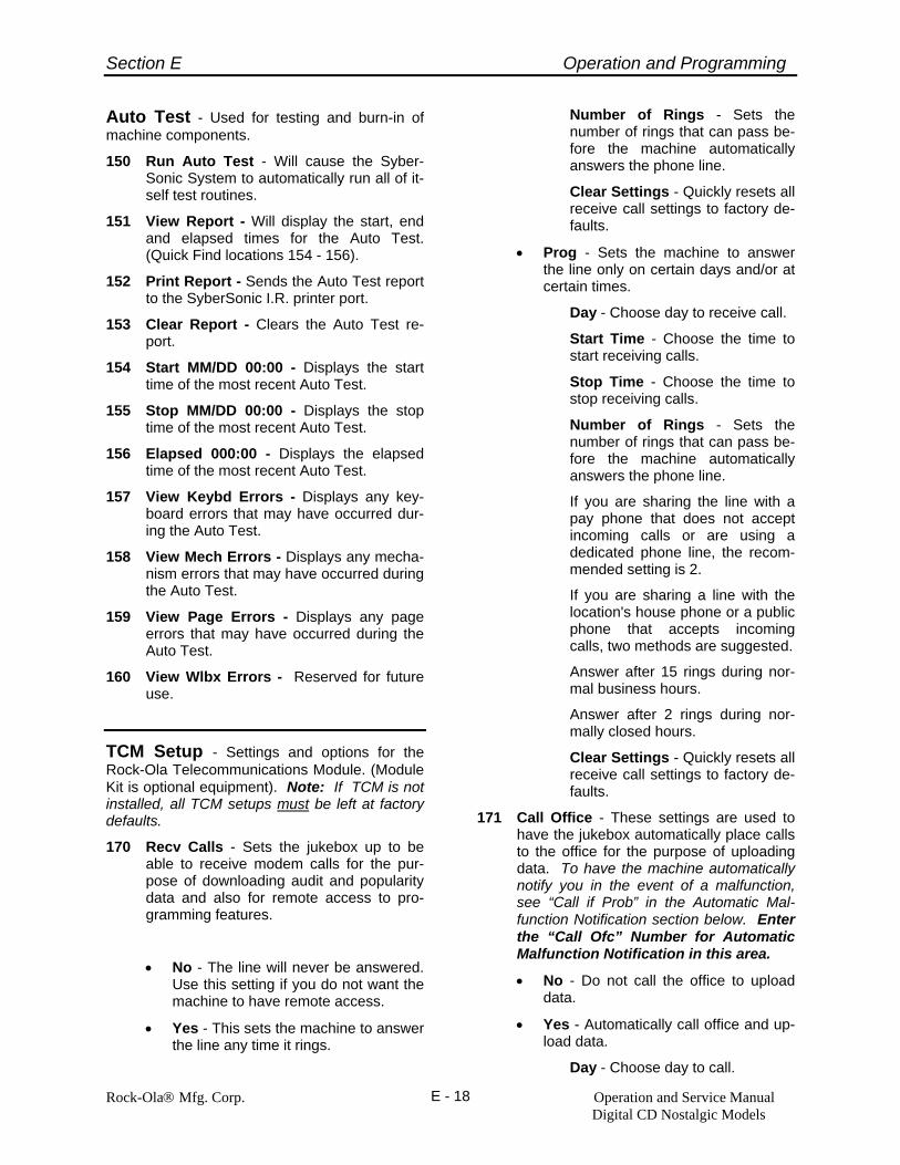
Section E Operation and Programming
Rock-Ola® Mfg. Corp. Operation and Service Manual Digital CD Nostalgic Models
E - 18
Auto Test - Used for testing and burn-in of machine components.
150 Run Auto Test - Will cause the Syber-Sonic System to automatically run all of it-self test routines.
151 View Report - Will display the start, end and elapsed times for the Auto Test. (Quick Find locations 154 - 156).
152 Print Report - Sends the Auto Test report to the SyberSonic I.R. printer port.
153 Clear Report - Clears the Auto Test re-port.
154 Start MM/DD 00:00 - Displays the start time of the most recent Auto Test.
155 Stop MM/DD 00:00 - Displays the stop time of the most recent Auto Test.
156 Elapsed 000:00 - Displays the elapsed time of the most recent Auto Test.
157 View Keybd Errors - Displays any key-board errors that may have occurred dur-ing the Auto Test.
158 View Mech Errors - Displays any mecha-nism errors that may have occurred during the Auto Test.
159 View Page Errors - Displays any page errors that may have occurred during the Auto Test.
160 View Wlbx Errors - Reserved for future use.
TCM Setup - Settings and options for the Rock-Ola Telecommunications Module. (Module Kit is optional equipment). Note: If TCM is not installed, all TCM setups must be left at factory defaults.
170 Recv Calls - Sets the jukebox up to be able to receive modem calls for the pur-pose of downloading audit and popularity data and also for remote access to pro-gramming features.
• No - The line will never be answered. Use this setting if you do not want the machine to have remote access.
• Yes - This sets the machine to answer the line any time it rings.
Number of Rings - Sets the number of rings that can pass be-fore the machine automatically answers the phone line.
Clear Settings - Quickly resets all receive call settings to factory de-faults.
• Prog - Sets the machine to answer the line only on certain days and/or at certain times.
Day - Choose day to receive call.
Start Time - Choose the time to start receiving calls.
Stop Time - Choose the time to stop receiving calls.
Number of Rings - Sets the number of rings that can pass be-fore the machine automatically answers the phone line.
If you are sharing the line with a pay phone that does not accept incoming calls or are using a dedicated phone line, the recom-mended setting is 2.
If you are sharing a line with the location's house phone or a public phone that accepts incoming calls, two methods are suggested.
Answer after 15 rings during nor-mal business hours.
Answer after 2 rings during nor-mally closed hours.
Clear Settings - Quickly resets all receive call settings to factory de-faults.
171 Call Office - These settings are used to have the jukebox automatically place calls to the office for the purpose of uploading data. To have the machine automatically notify you in the event of a malfunction, see “Call if Prob” in the Automatic Mal-function Notification section below. Enter the “Call Ofc” Number for Automatic Malfunction Notification in this area.
• No - Do not call the office to upload data.
• Yes - Automatically call office and up-load data.
Day - Choose day to call.

Section E Operation and Programming
Rock-Ola® Mfg. Corp. Operation and Service Manual Digital CD Nostalgic Models
E - 19
Start Time - Choose the time to enable automatic calling.
Stop Time - Choose the time to disable automatic calling.
Telephone Number - The num-ber to which the data is to be up-loaded. This is entered the same way that a custom message is en-tered. (See the section describing message entry for detailed in-structions.) Allowable characters are the numerals 0-9, *, # and capitol P.
A character “P” inserted into a telephone number will cause a 1 second delay after the “P." “PP” will cause a 2 second delay, “PPP” will cause a 3 second de-lay, etc. The pause is used to create a delay to allow for the en-try of a calling (credit) card num-ber, to wait for an outside line, etc.
Retries - Number of times TCM should try to send the message in the event of a communications malfunction.
Clear Settings - Quickly resets the “Call Office” features to the factory defaults.
172 Call if Problem
• No - Do not call for any malfunction.
• Yes - Call if a selected malfunction occurs. (The malfunctions will be se-lected below.)
Enter Pager Number - If the ma-chine is set to notify via pager, the telephone number, identification code (in any) and function numbers (if any) are entered here. This in-cludes any dialing prefixes and suf-fixes. This is entered the same way that a custom message is entered. (See the section describing mes-sage entry below for detailed in-structions.) Allowable characters are the numerals 0-9, *, # and capitol P.
A character “P” inserted into a tele-phone number will cause a 1 sec-ond delay after the “P." “PP” will cause a 2 second delay, “PPP” will cause a 3 second delay, etc. The
pause is used to create a delay to allow the paging system to respond and for the entry of a calling (credit) card number, to wait for an outside line, etc. Additional pauses may also be necessary if your paging service requires an access code. Important! A minimum of 3 P’s are necessary ( 3 second delay) after the pager number to allow the paging system time to re-spond. If no pause time is al-lowed, the paging system will not be able to properly receive and then transmit the data to you.
An example of a typical “direct dial” pager dialing string may look like: 5554567PPPP where 5554567 is the pager number and PPPP is a 4 second pause to allow the paging system to answer and respond be-fore the jukebox sends its error code information. To know exactly how many P’s to insert into the dial-ing string, call your pager number from the phone line that the jukebox is plugged into and count the num-ber of seconds from the time the last button is pushed until the paging service responds. Add one more second to that number and insert the corresponding number of pauses into the dialing string.
Another example: the following is used to call a Skytel® Pager:
18007598888PPPPP#nnnnn#PPPP
In the above example,
18007598888 is the access number, PPPPP causes a 5 second delay to wait for the Skytel system to an-swer, #nnnnnnn# represent the “PIN” number and PPPP gives the paging system time to respond be-fore the jukebox sends its error code.
Enter Pager Suffix - This is a string of characters that ends the paging cycle after the error code is sent. i.e. A Skytel Pager requires 2 “#” tones be sent to end the paging cy-cle.
Pages to Send - The number of times to successfully send the page. This setting is included to compen-

Section E Operation and Programming
Rock-Ola® Mfg. Corp. Operation and Service Manual Digital CD Nostalgic Models
E - 20
sate for paging systems that have a tendency to “miss” some pages. The system will retry if the location line is in use until it is successful.
Report DBA Jam
Yes - Will cause the machine to page and post a message at the office in the event of a jammed or full DBA. The “office” number to be called is the same one as set in Call Office (Quick Find 171).
No - Will cause the machine to ignore this malfunction.
Ofc - Will cause the machine to only post a message at the of-fice.
Pgr - Will cause the machine to only page in the event of this malfunction.
Report Fatal Error
Yes - Will cause the machine to page and post a message at the office in the event of a “fatal er-ror” such as an inoperative mechanism. The “office” num-ber to be called is the same one as set in Call Office (Quick Find 171).
No - Will cause the machine to ignore this malfunction.
Ofc - Will cause the machine to only post a message at the of-fice.
Pgr - Will cause the machine to only page in the event of this malfunction.
Report Break In
Yes - Will cause the machine to page and post a message at the office in the event of an unau-thorized entry into the jukebox. The “office” number to be called is the same one as set in Call Office (Quick Find 171).
No - Will cause the machine to ignore this malfunction.
Ofc - Will cause the machine to only post a message at the of-fice.
Pgr - Will cause the machine to only page in the event of this malfunction.
Note: Setup mode must be ac-cessed and password entered (if enabled) within 30 seconds of opening the lid or else the break-in warning will be sent.
Report CD Errors
Yes - Will cause the machine to page and post a message at the office in the event of 50 CD playing errors in one day. The “office” number to be called is the same one as set in Call Of-fice (Quick Find 171)
No - Will cause the machine to ignore this malfunction.
Ofc - Will cause the machine to only post a message at the of-fice.
Pgr - Will cause the machine to only page in the event of this malfunction.
Clear Settings - Will quickly restore the factory default settings for the ma-chine’s power. Call if Problem options.
175 Modem
• Rock-Ola - This setting is to be used for the Rock-Ola modem provided in the 2417-02 kit.
• DELETE Sentence in parenthesis after Rckwl 14.4
• Off - This setting is turns the entire Telecommunications system off. Use when no modem is installed, or you do not the telecommunications to operate.
• Direct - This setting is used to connect the jukebox to a PC via a serial cable. After connecting the jukebox to the PC, choose this setting. Press the Can-cel/scan button to exit the session, then return the setting to the off or the correct modem type.
176 Telecommunications Password
This is the four digit password used to identify this jukebox by the “Get Con-

Section E Operation and Programming
Rock-Ola® Mfg. Corp. Operation and Service Manual Digital CD Nostalgic Models
E - 21
nected” program. If it is left at the factory default of “0000” then it can be changed by remote control.
177 Reset Telecommunications ID
This clears the ID code assigned to the jukebox by the “Get Connected” program.
Resetting the ID means the jukebox will no longer be linked to the existing jukebox pro-file in the “Get Connected” program. This should only be necessary when you are sell-ing the jukebox or discontinuing the use of the modem.
Amp Setup- Provides access to the Equal-izer, Balance, Music Level While Paging, Page Decay and Factory Reset functions for the Digi-tal SyberSonic Amplifiers. Detailed amplifier descriptions and programming instructions are located in Section D of this manual.
210 Internal Amp – Provides access to the standard Digital Amplifier setting options. When chosen will jump to Quick Find 213, Int. Equalizer.
211 External Amp – Provides access to the optional Auxiliary Digital Amplifier setting options. When chosen will jump to Quick Find 222, Ext. Equalizer.
212 Page Decay – Sets the delay time, in seconds, that the music will “fade” back to the set volume. Page decay is set for all channels simultaneously.
213 Int. Equalizer - Sets the 7 band graphic equalizer for the internal amplifier.
214 Int. Balance - Sets the left to right bal-ance for the internal amplifier.
215 Int. MLWP - Sets the Music Level While Paging for the internal amplifier. The MLWP is a percentage of the music vol-ume heard while the paging microphone is used. If selected, will jump to Quick Find 218. Left and Right Channels are set separately via Quick Find 218 and Quick Find 219 respectively.
216 Int. Loudness - Sets the loudness con-tour for the internal amplifier. If selected, will jump to Quick Find 220. Left and Right channels are set separately via Quick Find 220 and Quick Find 221 re-spectively.
217 Reset Int. Amp - Quickly restores set-tings for the internal amplifier to their fac-tory settings.
218 Internal Left MLWP – Set how much of the music is heard through the Internal Left channel during a “page.”
219 Internal Right MLWP – Sets how much of the music is heard through the Internal Right Channel during a “page.”
220 Internal Left Loudness – Turns the loudness contour on or off for the Internal Amplifier’s Left Channel.
221 Internal Right Loudness – Turns the loud-ness contour on or off for the Internal Am-plifier’s Right Channel.
231 Internal AVC – Turns the Automatic Vol-ume Control on or off for the Internal Amplifier.
222 Ext. Equalizer - Sets the 7 band graphic equalizer for the optional Auxiliary Digital Amplifier.
223 Ext. Balance - Sets the left to right bal-ance for the optional Auxiliary Digital Amplifier.
224 Ext. MLWP - Sets the Music Level While Paging for the external amplifier. The MLWP is a percentage of the music vol-ume heard while the paging microphone is used. If selected, will jump to Quick Find 227. Left and Right Channels are set separately via Quick Find 227 and Quick Find 228 respectively.
225 Ext. Loudness - Sets the loudness con-tour for the external amplifier. If selected, will jump to Quick Find 229. Left and Right Channels are set separately via Quick Find 229 and Quick Find 230 re-spectively.
226 Reset Ext. Amp - Quickly restores set-tings for the external amplifier to their fac-tory settings.
227 External Left MLWP – Set how much of the music is heard through the External Left channel during a “page.”
228 External Right MLWP – Set how much of the music is heard through the Exter-nal Right channel during a “page.”

Section E Operation and Programming
Rock-Ola® Mfg. Corp. Operation and Service Manual Digital CD Nostalgic Models
E - 22
229 External Left Loudness – Turns the loudness contour on or off for the Exter-nal Amplifier’s Left Channel.
230 External Right Loudness – Turns the loudness contour on or off for the Exter-nal Amplifier’s Right Channel.
232 External AVC – Turns the Automatic Volume Control on or off for the External Amplifier.
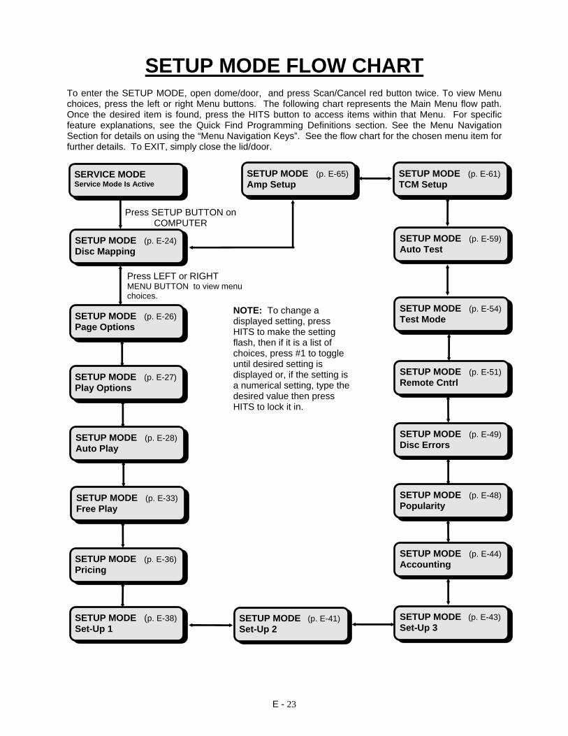
E - 23
SETUP MODE FLOW CHART
To enter the SETUP MODE, open dome/door, and press Scan/Cancel red button twice. To view Menu choices, press the left or right Menu buttons. The following chart represents the Main Menu flow path. Once the desired item is found, press the HITS button to access items within that Menu. For specific feature explanations, see the Quick Find Programming Definitions section. See the Menu Navigation Section for details on using the “Menu Navigation Keys”. See the flow chart for the chosen menu item for further details. To EXIT, simply close the lid/door.
Press SETUP BUTTON on COMPUTER
SETUP MODE (p. E-24) Disc Mapping
SETUP MODE (p. E-26) Page Options
SERVICE MODE Service Mode Is Active
SETUP MODE (p. E-27) Play Options
SETUP MODE (p. E-28) Auto Play
SETUP MODE (p. E-33) Free Play
SETUP MODE (p. E-36) Pricing
SETUP MODE (p. E-38) Set-Up 1
SETUP MODE (p. E-54)Test Mode
SETUP MODE (p. E-51)Remote Cntrl
SETUP MODE (p. E-49)Disc Errors
SETUP MODE (p. E-48)Popularity
SETUP MODE (p. E-44)Accounting
SETUP MODE (p. E-43) Set-Up 3
SETUP MODE (p. E-41) Set-Up 2
SETUP MODE (p. E-59)Auto Test
SETUP MODE (p. E-61) TCM Setup
Press LEFT or RIGHT MENU BUTTON to view menu choices.
NOTE: To change a displayed setting, press HITS to make the setting flash, then if it is a list of choices, press #1 to toggle until desired setting is displayed or, if the setting is a numerical setting, type the desired value then press HITS to lock it in.
SETUP MODE (p. E-65) Amp Setup

E - 24
DISC MAPPING DISC MAPPING Disc Mapping
DISC MAPPING 10 Map Off
HITS DISC MAPPING 10 Map All Slots
#1
DISC MAPPING 10 Map Empty Slots
DISC MAPPING 10 Map Single Slots
DISC MAPPING 10 Map Clear
DISC MAPPING 10 Map CD Number --
HITS
#1
#1
#1
#1
DISC MAPPING 11 Track Lockouts
DISC MAPPING 15 View Lockouts
RT MENU
HITS
DISC MAPPING 16 Clear Lockouts
DISC MAPPING 15 Omit Track ----
DISC MAPPING 15 End of Lockouts
RT MENU
HITS*
HITS*If none exist
If existing
To add lockouts Press HITS
DISC MAPPING 15 Day None/EveryDay/SMTWTFS
HITS*
DISC MAPPING 15 Start Time 00:00 – 23:59
RT MENU
DISC MAPPING 15 Stop Time 00:00 – 23:59
RT MENU
DISC MAPPING 15 Omit Track # Just Entered
RESET
RT MENU
* To edit existing lockouts, display first lockout then use MENU buttons to access the desired lockout, press HITS then make changes. To add lockouts, go to “End of Lockouts”, press Hits then enter new lockout.
DISC MAPPING 16 Are You Sure?
DISC MAPPING 16 Action Done
HITS
HITS
* Use MENU buttons to scroll through lockouts
DISC MAPPING 10 Map Off
HITS

E - 25
DISC MAPPING 12 Disc Lockouts
DISC MAPPING 17 View Lockouts
HITS
DISC MAPPING 18 Clear Lockouts
DISC MAPPING 17 Omit Disc --
RT MENU
HITS*
HITS*If none exist
If existing
To add lockouts Press HITS
DISC MAPPING 17 Day None/EveryDay/SMTWTFS
HITS*
DISC MAPPING 17 Start Time 00:00 – 23:59
RT MENU
DISC MAPPING 17 Stop Time 00:00 – 23:59
RT MENU
DISC MAPPING 17 Omit Disc # Just Entered
RESET
RT MENU
* To edit existing lockouts, display first lockout then use MENU buttons to access the desired lockout, press HITS then make changes. To add lockouts, go to “End of Lockouts”, press Hits then enter new lockout.
DISC MAPPING 18 Are You Sure?
DISC MAPPING 18 Action Done
HITS
HITS
DISC MAPPING 17 End of Lockouts
DISC MAPPING 13 Special Discs
DISC MAPPING 19 View Specials
DISC MAPPING 20 Clear Specials
DISC MAPPING 20 Are You Sure?
DISC MAPPING 20 Action Done
DISC MAPPING 19 Disc 00: Normal
DISC MAPPING 19 Disc 01: Normal
DISC MAPPING 19 Disc …: Normal
DISC MAPPING 19 Disc 99: Normal
HITS HITS*
HITS
HITS
RT MENU RT MENU
RT MENU
RT MENU
* Use MENU buttons to scroll through lockouts
*To set Specials, scroll to disc number, press Hits, press #1 to display desired setting, press Hits to lock in
DISC MAPPING 14 Special Vid. No
DISC MAPPING 14 Special Vid Yes/No
HITS

E - 26
PAGE OPTIONS
SETUP MODE Page Options
PAGE OPTIONS 25 Pages Fireball
PAGE OPTIONS 25 Pages Legend/Nostalgia/Rocket/Intrigue/Fireball
PAGE OPTIONS 27 Set Home Page 01
PAGE OPTIONS 27 Set Home Page 00/99
PAGE OPTIONS 28 Home Delay 05
PAGE OPTIONS 28 Home Delay 00/99
PAGE OPTIONS 29 Remote Pages Off
PAGE OPTIONS 29 Remote Pages On/Off
PAGE OPTIONS 26 Set last Page 06
PAGE OPTIONS 26 Set last Page 00/99
HITS HITS
HITS
HITS
HITS
HITS
RT MENU
RT MENU
RT MENU
RT MENU
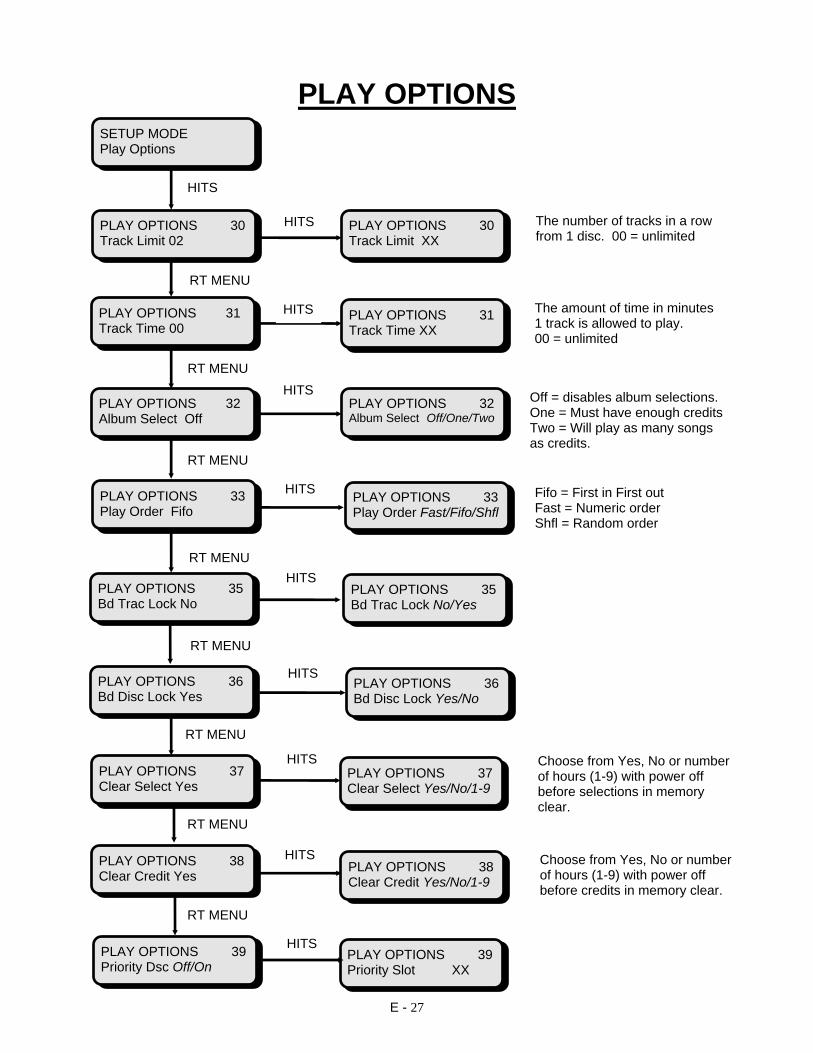
E - 27
PLAY OPTIONS
PLAY OPTIONS 35 Bd Trac Lock No
PLAY OPTIONS 35 Bd Trac Lock No/Yes
PLAY OPTIONS 38 Clear Credit Yes
PLAY OPTIONS 36 Bd Disc Lock Yes/No
HITS
HITS
RT MENU
SETUP MODE Play Options
PLAY OPTIONS 30 Track Limit 02
PLAY OPTIONS 30 Track Limit XX
PLAY OPTIONS 31 Track Time 00
PLAY OPTIONS 31 Track Time XX
PLAY OPTIONS 32 Album Select Off
PLAY OPTIONS 32 Album Select Off/One/Two
PLAY OPTIONS 33 Play Order Fifo
PLAY OPTIONS 33 Play Order Fast/Fifo/Shfl
The number of tracks in a row from 1 disc. 00 = unlimited
The amount of time in minutes 1 track is allowed to play. 00 = unlimited
Off = disables album selections. One = Must have enough creditsTwo = Will play as many songs as credits.
Fifo = First in First out Fast = Numeric order Shfl = Random order
HITS
HITS
HITS
HITS
HITS
RT MENU
RT MENU
RT MENU
RT MENU
PLAY OPTIONS 36 Bd Disc Lock Yes
PLAY OPTIONS 37 Clear Select Yes
PLAY OPTIONS 39 Priority Dsc Off/On
PLAY OPTIONS 37 Clear Select Yes/No/1-9
PLAY OPTIONS 38 Clear Credit Yes/No/1-9
PLAY OPTIONS 39 Priority Slot XX
HITS
HITS
HITS
RT MENU
RT MENU
RT MENU
Choose from Yes, No or number of hours (1-9) with power off before selections in memory clear.
Choose from Yes, No or number of hours (1-9) with power off before credits in memory clear.

E - 28
AUTO PLAY HITS HITS RT MENU HITS #1 RT MENU HITS HITS HITS HITS RT MENU RT MENU RT MENU
SETUP MODE Auto Play
AUTO PLAY 40 Auto Play Off
AUTO PLAY 40 Auto Play Random
AUTO PLAY 40 View Settings
AUTO PLAY 40 Clear Settings
AUTO PLAY 40 Are You Sure?
AUTO PLAY 40 Action Done
AUTO PLAY 40 Random - 01 - 21
AUTO PLAY 40 Day None/Every/SMTWTFS
AUTO PLAY 40 Start CD 00 -99
AUTO PLAY 40 End CD 00 - 99

E - 29
RT MENU RT MENU HITS #1 RT MENU HITS HITS HITS RT MENU HITS RT MENU HITS HITS HITS HITS
AUTO PLAY 40 Start Time 00:00 - 23:59
AUTO PLAY 40 Stop Time 00:00 - 23:59
AUTO PLAY 40 Time Interval 00 - 99
AUTO PLAY 40 Auto Play Progrm
AUTO PLAY 40 Pgrm. Selections
AUTO PLAY 40 Program Settings
AUTO PLAY 40 View Selections
AUTO PLAY 40 View Settings
AUTO PLAY 40 Clear Selections
AUTO PLAY 40 Are You Sure?
AUTO PLAY 40 Clear Settings
AUTO PLAY 40 Action Done
AUTO PLAY 40 Are You Sure?
AUTO PLAY 40 Action Done

E - 30
RT MENU HITS RT MENU RT MENU RT MENU RT MENU RT MENU HITS RT MENU HITS RT MENU
AUTO PLAY 40 Select. 01: XXXX
AUTO PLAY 40 Program - 01 - 21
AUTO PLAY 40 Select. 02: XXXX
AUTO PLAY 40 Select ...: XXXX
AUTO PLAY 40 Select. 99: XXXX
AUTO PLAY 40 Day None/Every/SMTWTFS
AUTO PLAY 40 Start Time 00:00 - 23:59
AUTO PLAY 40 Stop Time 00:00 - 23:59
AUTO PLAY 40 Time Interval 00 - 99
AUTO PLAY 40 Auto Play Code
AUTO PLAY 40 Code Selections
AUTO PLAY 40 Time Interval 00 - 99

E - 31
RT MENU HITS RT MENU HITS RT MENU HITS RT HITS MENU RT MENU HITS HITS HITS HITS RT MENU RT MENU RT MENU
AUTO PLAY 40 Auto Code 0000 - 9999
AUTO PLAY 40 View Selections
AUTO PLAY 40 Clear Selections
AUTO PLAY 40 Are You Sure?
AUTO PLAY 40 Action Done
AUTO PLAY 40 Select. 01: XXXX
AUTO PLAY 40 Select. ...: XXXX
AUTO PLAY 40 Select. 99: XXXX
AUTO PLAY 41 Background Off / On
AUTO PLAY 41 View Settings
AUTO PLAY 41 Clear Settings
AUTO PLAY 41 Background - 01 - 21
AUTO PLAY 41 Are You Sure?
AUTO PLAY 41 Action Done
AUTO PLAY 41 Day None/Every/SMTWTFS
AUTO PLAY 41 Start CD 00 - 99
AUTO PLAY 41 End CD 00 - 99

E - 32
RT MENU RT MENU Off = No Aux. BGM Input One = No BGM input between JB selections Two = BGM input live between JB selections RT MENU HITS HITS RT MENU RT MENU HITS RT MENU HITS RT MENU HITS RT MENU
AUTO PLAY 41 Start Time 00:00-23:59
AUTO PLAY 42 Aux Backgrnd Off/One/Two
AUTO PLAY 43 Background Vol.
AUTO PLAY 43 Min Int Level 01
AUTO PLAY 43 Min Int Level 01 - 40
AUTO PLAY 43 Max Int Level 01- 40
AUTO PLAY 44 End Style Fade/Finish/Cancel
AUTO PLAY 43 Min Ext Level 01 - 40
AUTO PLAY 45 Hits Button View/Play/VT
AUTO PLAY 43 Max Int Level 20
AUTO PLAY 43 Min Ext Level 01
AUTO PLAY 43 Max Ext Level 20
AUTO PLAY 43 Max Ext Level 01 - 40
AUTO PLAY 41 Stop Time 00:00-23:59
AUTO PLAY 41 Time Interval 00-99
V/T = View and turn to page
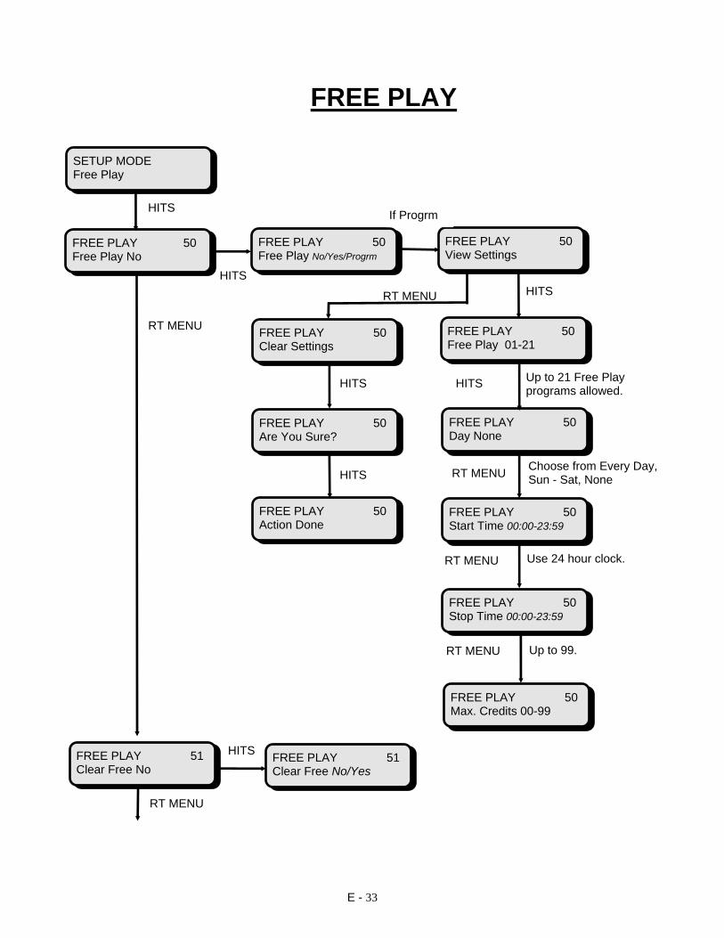
E - 33
FREE PLAY
RT MENU
SETUP MODE Free Play
FREE PLAY 50 Free Play No
FREE PLAY 50 Free Play No/Yes/Progrm
FREE PLAY 50 View Settings
FREE PLAY 50 Clear Settings
FREE PLAY 50 Free Play 01-21
FREE PLAY 50 Day None
FREE PLAY 50 Are You Sure?
FREE PLAY 50 Action Done
FREE PLAY 50 Start Time 00:00-23:59
FREE PLAY 50 Stop Time 00:00-23:59
FREE PLAY 50 Max. Credits 00-99
FREE PLAY 51 Clear Free No
FREE PLAY 51 Clear Free No/Yes
Up to 21 Free Play programs allowed.
Choose from Every Day, Sun - Sat, None
Use 24 hour clock.
Up to 99.
If Progrm
RT MENU
HITS
RT MENU
RT MENU
RT MENU
HITS HITS
HITS
HITS HITS
HITS
RT MENU
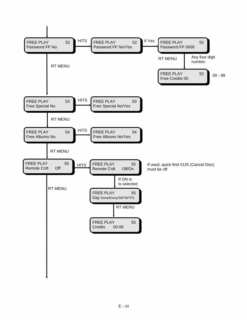
E - 34
RT MENU HITS If ON is is selected RT MENU RT MENU
FREE PLAY 52 Password FP No
FREE PLAY 52 Password FP No/Yes
FREE PLAY 52 Password FP 0000
FREE PLAY 52 Free Credits 00
FREE PLAY 53 Free Special No
FREE PLAY 53 Free Special No/Yes
FREE PLAY 54 Free Albums No
FREE PLAY 54 Free Albums No/Yes
Any four digit number.
00 - 99
If Yes
RT MENU
RT MENU
RT MENU
HITS
HITS
HITS
FREE PLAY 55 Remote Crdt Off
FREE PLAY 55 Remote Crdt Off/On
FREE PLAY 55 Day None/Every/SMTWTFS
FREE PLAY 55 Credits 00-99
If used, quick find #125 (Cancel Disc) must be off.

E - 35
FREE PLAY 56 Free Selections
FREE PLAY 56 View Normal
FREE PLAY 56 End Normal
FREE PLAY 56 Normal 01: ----
FREE PLAY 56 End Normal
Clear priority repeats the same as clear normal.
FREE PLAY 56 Clear Normal
FREE PLAY 56 Are you sure?
FREE PLAY 56 Action Done
FREE PLAY 56 View Priority
FREE PLAY 56 End Priority
FREE PLAY 56 Priority 01: ----
FREE PLAY 56 Clear Priority
FREE PLAY 56 End Priority
FREE PLAY 56 Are you sure?
FREE PLAY 56 Action Done
HITS
HITS
HITS
Up to 50 RT MENU
HITS
HITS
HITS
HITS
Up to 50 RT MENU
HITS
HITS
RT MENURT MENU
RT MENU

E - 36
PRICING
HITS Possible Values 001 - 100 RT MENU HITS Possible Values for All Input Rates 001 - 999 RT MENU RT MENU RT MENU RT MENU RT MENU * 005 if 25 cents only * 020 if 25cents/$1 coin RT MENU
SETUP MODE Pricing
PRICING 60 Unit Price 005
PRICING 61 Input Rates
PRICING 61 Input 1 Rate 001
PRICING 61 Input 2 Rate 002
PRICING 61 Input 3 Rate 005
PRICING 61 Input 4 Rate 005
PRICING 61 Input 5 Rate *
PRICING 61 Input 6 Rate 020

E - 37
HITS Possible Values for All 4 Pricing Levels 00-000 - 99-999 RT MENU RT MENU RT MENU RT MENU Possible Values 01 - 99 RT MENU RT MENU Possible Values HITS RT MENU 1 - 4 RT MENU HITS RT MENU Possible Values 01 - 99 RT MENU RT MENU HITS HITS HITS (if on)
PRICING 62 Pricing Levels
PRICING 62 Credits / $ 01-050
PRICING 62 Credits / $ 02-100
PRICING 62 Credits / $ 05-200
PRICING 62 Credits / $ 15-500
PRICING 63 Credits Spec. 02
PRICING 64 Recirculate Lv. 1
PRICING 65 Acct. Unit 20
PRICING 66 Timed Bonus Off/On
PRICING 66 View Settings
PRICING 66 Timed Bonus - 01-21
PRICING 66 Day None/Every/SMTWTFS
PRICING 66 Start Time 00:00 - 23:59
PRICING 66 Stop Time 00:00 - 23:59
PRICING 66 Free/Paid 01/03
PRICING 66 Clear Settings
PRICING 66 Are You Sure?
PRICING 66 Action Done

E - 38
SET-UP 1 HITS RT MENU Possible Values 00 - 99 RT MENU HITS HITS RT MENU HITS HITS RT MENU HITS Possible Value Any Valid Date RT MENU RT MENU Possible Values 00:00 - 23:59 Use 24 Hour Clock RT MENU Choose From Sunday through Saturday
SET-UP MODE Set-Up 1
SET-UP 1 70 Remote Power On/Off
SET-UP 1 71 Serv. Credits 00
SET-UP 1 72 Clear Selections
SET-UP 1 72 Are You Sure?
SET-UP 1 72 Action Done
SET-UP 1 73 Clear Credits
SET-UP 1 73 Are You Sure?
SET-UP 1 73 Action Done
SET-UP 1 74 Set Clock/Date
SET-UP 1 74 SetDate 12/25/96
SET-UP 1 74 Set Clock 12:00
SET-UP 1 74 Day Wednesday

E - 39
If HITS Program RT MENU RT MENU HITS HITS HITS Use Page Keys to scroll through the available characters. When found, press HITS. To enter next letter, use Page Keys to find character and HITS press HITS. When finished, press RESET to take you back to “Change Message” HITS HITS RESET WHEN FINISHED Possible Values 01 - 14 RT MENU HITS If Yes RT MENU
SET-UP 1 75 Message Factory
SET-UP 1 75 Message Off/Factory/Progrm
SET-UP 1 75 Clear Message
SET-UP 1 75 Are You Sure?
SET-UP 1 75 Action Done
SET-UP 1 75 Change Message
‘A’
A ‘b’
Ab ‘b’
SET-UP 1 76 Scroll Rate 05
SET-UP 1 77 Auto Clean No
SET-UP 1 77 CD Cleaner 99

E - 40
SET-UP 1 78 Volume Range Off
SET-UP 1 78 Volume Range Off/On
SET-UP 1 78 Internal Limits
SET-UP 1 78 External Limits
SET-UP 1 78 Min Vol Level 01-40
SET-UP 1 79 Volume Current Setting
SET-UP 1 79 Volume Norm/Split/Bridge
SET-UP 1 79 Bridge Int - Ext B
SET-UP 1 79 Bridge Int - Ext choice
RT MENU
HITS
SET-UP 1 78 System Min/Max
SET-UP 1 78 Max Vol Level 01-40
If setting is OK press RESET Else press HITS then #1 to toggle choice. See Section D for Volume Control option details.
SET-UP 1 79 Bridge Int - Ext B/R/L
HITS
HITS
IF ON,HITS
RT MENU
HITS
SET-UP 1 78 Min Vol Level 01-40
SET-UP 1 78 System Min/Max
SET-UP 1 78 Max Vol Level 01-40
HITS
HITS
HITS
HITS If Bridge,HITS
HITS
HITS
RT MENU

E - 41
SET-UP 2 HITS HITS Must have a security level “3” set before setting another security Level to “1” or “2” RT MENU HITS RT MENU HITS RT MENU RT MENU HITS RT MENU HITS HITS RT MENU RT MENU RT MENU HITS RT MENU
SET-UP MODE Set-Up 2
SET-UP 2 80 Password 1: XXXX
SET-UP 2 81 Password 2: XXXX
SET-UP - 2 82 Password 3: XXXX
SET-UP 2 83 Serial Num: XXXX
SET-UP 2 84 Print Menus
SET-UP 2 84 Printing...
SET-UP 2 85 Service Record SET-UP 2 85
03/24 10:41 PW 1
SET-UP 2 85 Next Record
SET-UP 2 80 PW 1 Security: 0-3
SET-UP 2 81 PW 2 Security: 0-3
SET-UP 2 82 PW 3 Security 0-3
SET-UP 2 85 View Svc Record
SET-UP 2 85 Print Svc Record
SET-UP 2 85 Printing…
SET-UP 2 85 End of Record

E - 42
Choose from All / Kybd RT MENU HITS HITS Choose from Comm or Home HITS RT MENU HITS Choose from English, Spanish German, Portuguese, French, Czech or Finnish. RT MENU
Fade will cause the song’s volume to increase to set level. Norm will cause song to start at the set volume level.
SET-UP 2 86 Counter Out All
SET-UP 2 87 Factory Reset
SET-UP 2 87 Factory Set Xxxx
SET-UP 2 87 Are You Sure?
SET-UP 2 87 Please Wait...
SET-UP 2 87 Action Done
SET-UP 2 88 Lang. English
SET-UP 2 89 Start Style Fade/Norm

E - 43
SET-UP 3 Range is 000-999. If an invalid “hotkey” is entered, menu entry will default to normal entry point: “Disc Mapping”
SETUP MODE Set-Up 3
SET-UP 3 200 Open Menu Id 000-999
HITS
SET-UP 3 201 Auto Power Off
SET-UP 3 201 Auto Power Off/On
SET-UP 3 201 View Settings
SET-UP 3 201 Reset Settings
SET-UP 3 201 Are You Sure?
SET-UP 3 201 Action Done
SET-UP 3 201 Auto Power 1-7
SET-UP 3 201 Day None
SET-UP 3 201 Power On 00:00-23:59
SET-UP 3 201 Power Off 00:00-23:59
SET-UP 3 202 Amp Mute On
SET-UP 3 202 Amp Mute On/Off
RT MENU
RT MENU
HITS IF ON
RT MENU
HITS
HITS
HITS
RT MENU
RT MENU
Up to 7 power programs allowed
HITS

E - 44
ACCOUNTING
RT MENU
SETUP MODE Accounting
ACCOUNTING 90 Last Reset 12/25 12:30
ACCOUNTING 91 Print Acc. Data
ACCOUNTING 91 Printing...
ACCOUNTING 92 Basic Acct.
ACCOUNTING 92 Total Selections
ACCOUNTING 92 Ptd Selections
ACCOUNTING 92 Total Plays
ACCOUNTING 92 Ptd Plays
ACCOUNTING 92 Total Cash
ACCOUNTING 92 Ptd Cash
ACCOUNTING 93 Total Selections
ACCOUNTING 93 Total Acct.
ACCOUNTING 93 Ptd Selections
ACCOUNTING 93 Total Local Norm
ACCOUNTING 93 Ptd Local Norm
HITS
HITS
HITS
RT MENU
HITS
RT MENU
RT MENU
RT MENU
HITS
RT MENU
RT MENU
RT MENU
RT MENU
RT MENU
RT MENU
RT MENU

E - 45
HITS RT MENU
ACCOUNTING 93 Total Local Spec
ACCOUNTING 93 Ptd Local Spec
ACCOUNTING 93 Total Walbx Norm
ACCOUNTING 93 Ptd Walbx Norm
ACCOUNTING 93 Total Walbx Spec
ACCOUNTING 93 Ptd Walbx Spec
ACCOUNTING 93 Wallbox Detail
ACCOUNTING 93 Total Cash
ACCOUNTING 93 Ptd Cash
ACCOUNTING 93 Ptd Coin Inputs
ACCOUNTING 93 Ptd Coin Input 1
ACCOUNTING 93 Ptd Coin Input 2
ACCOUNTING 93 Ptd Coin Input 3
ACCOUNTING 93 Ptd Coin Input 4
ACCOUNTING 93 Ptd Coin Input 5
ACCOUNTING 93 Ptd Coin Input 6
RT MENU
RT MENU
HITS RESET
RT MENU
RT MENU
RT MENU
RT MENU
RT MENU
RT MENU
RT MENU
RT MENU
RT MENU
RT MENU
RT MENU
RT MENU
ACCOUNTING 93 Total Walbx Cash
ACCOUNTING 93 Ptd Walbx Cash

E - 46
ACCOUNTING 93 Total Free Pct
ACCOUNTING 93 Ptd Free Pct
ACCOUNTING 93 Free Detail
ACCOUNTING 93 Total Album Buys
ACCOUNTING 93 Free Keybrd Norm
ACCOUNTING 93 Free Keybrd Spec.
ACCOUNTING 93 Free Remote Norm
ACCOUNTING 93 Free Remote Spec
ACCOUNTING 93 Self Play Select
ACCOUNTING 93 Ptd Album Buys
ACCOUNTING 93 Total Plays
ACCOUNTING 93 Ptd Plays
ACCOUNTING 93 Total Play Ratio
ACCOUNTING 93 Total Free Sel.
ACCOUNTING 93 Ptd Free Sel.
RT MENU
RT MENU
RT MENU
RT MENU
RT MENU
RT MENU
RT MENU
HITS RESET
RESET
RT MENU
RT MENU
RT MENU
RT MENU
RT MENU
RT MENU
RT MENU
ACCOUNTING 93 Timed Bonus Norm
ACCOUNTING 93 Timed Bonus Spcl
RT MENU

E - 47
ACCOUNTING 93 Ptd Avg. Price (Play)
ACCOUNTING 94 Clear PTD’s
ACCOUNTING 94 Are You Sure?
ACCOUNTING 94 Action Done
ACCOUNTING 95 View Level 1 No
ACCOUNTING 96 SP in Ratio No
ACCOUNTING 93 Ptd Play Ratio
ACCOUNTING 93 Total Avg. Price (Paid Play)
ACCOUNTING 93 Ptd Avg. Price (Paid Play)
ACCOUNTING 93 Total Avg. Price (Play)
RT MENU
RT MENU
RT MENU
RT MENU
RT MENU
HITS
HITS
RT MENU
Can choose from No / Yes
Can choose from No / Yes
ACCOUNTING 97 Power Cycles
ACCOUNTING 97 View Pwr Cycles
ACCOUNTING 97 10/30 16:00 0
ACCOUNTING 97 Print Pwr Cycles
ACCOUNTING 97 End of Record
RT MENU
HITS
RT MENU HITS
HITS RT MENU
ACCOUNTING 97 Printing…

E - 48
POPULARITY HITS HITS Choose from: Least Pop, Most Pop or CD Order (Will print and view popularity based upon this setting). RT MENU HITS RT MENU HITS RT MENU RT MENU RT MENU RT MENU HITS HITS
SETUP MODE Popularity
POPULARITY 100 Last Reset 12/25 12:30
POPULARITY 101 View Least Pop.
POPULARITY 102 Print Popularity
POPULARITY 102 Sorting...
POPULARITY 102 Printing...
POPULARITY 103 View Pop. Data
POPULARITY 103 Sorting....
POPULARITY 103 CD 00 Plays 0000
POPULARITY 103 CD 01 Plays 0000
POPULARITY 103 CD ..... Plays 0000
POPULARITY 103 CD 99 Plays 0000
POPULARITY 104 Clear Pop Data
POPULARITY 104 Are You Sure?
POPULARITY 104 Action Done
To change displayed CD, press button #1. To return disc to magazine, press button #2. More detail available in “Routine Service” section.

E - 49
DISC ERRORS HITS RT MENU HITS RT MENU HITS IF ERRORS EXIST RT MENU IF NO ERRORS RT MENU EXIST RT MENU HITS IF LOCKOUTS EXIST IF NO LOCKOUTS EXIST RT MENU RT MENU RT MENU
SETUP MODE Disc Errors
DISC ERRORS 110 View By Order/Errors
DISC ERRORS 111 Print Errors
DISC ERRORS 112 Playing Errors
DISC ERRORS 111 Printing...
DISC ERRORS 112 Sorting...
DISC ERRORS 112 Sel XXXX Errs XX
DISC ERRORS 112 Sel XXXX Errs XX
DISC ERRORS 112 End of Errors
DISC ERRORS 113 Locked Tracks
DISC ERRORS 113 Disc XX Track XX
DISC ERRORS 113 Disc XX Track XX
DISC ERRORS 113 End of Lockouts

E - 50
HITS IF MISSING DISC EXIST IF NO MISSING DISCS RT MENU RT MENU RT MENU HITS HITS
DISC ERRORS 114 Missing Discs
DISC ERRORS 114 Missing Disc XX
DISC ERRORS 114 Missing Disc XX
DISC ERRORS 114 End of Discs
DISC ERRORS 115 Clear Errors
DISC ERRORS 115 Are You Sure?
DISC ERRORS 115 Please Wait...
DISC ERRORS 115 Action Done

E - 51
REMOTE CONTROL HITS HITS RT MENU RT MENU RT MENU if “ON” HITS HITS RT MENU RT MENU RT MENU HITS RT MENU HITS RT MENU RT MENU
SETUP MODE Remote Cntrl
REMOTE CNTRL 120 Pause/Mute
REMOTE CNTRL 121 Select Type Off/Any/Free
REMOTE CNTRL 122 Rem Playlist Off/On
REMOTE CNTRL 122View Nxt Discs
REMOTE CNTRL 122Disc 00 Disabled/Enabled
REMOTE CNTRL 122Clear Nxt Discs
REMOTE CNTRL 122Are You Sure?
REMOTE CNTRL 122Action Done
REMOTE CNTRL 122Disc 01 Disabled/Enabled
REMOTE CNTRL 122Disc ... Disabled/Enabled
REMOTE CNTRL 122Disc 99 Disabled/Enabled
REMOTE CNTRL 123 Surround Snd On/Off
REMOTE CNTRL 120Pause Time 00/99
REMOTE CNTRL 120 Pause Suspend Op/Mute Music

E - 52
RT MENU RT MENU RT MENU RT MENU RT MENU If ON, HITS HITS RT MENU HITS RT MENU HITS HITS . RT MENU
REMOTE CNTRL 124 Select Album Off/On
REMOTE CNTRL 125 Cancel Disc Off/On
REMOTE CNTRL 126 Clear Mem. Off/On
REMOTE CNTRL 127 Random Sel.Off/On/Prog/One
REMOTE CNTRL 128 Background Off/On
REMOTE CNTRL 129 Play Lists Off/On
REMOTE CNTRL 129Play List 1
REMOTE CNTRL 129View Play List X (1 - 3)
REMOTE CNTRL 129Play List 2
REMOTE CNTRL 129Play List 3
If set to On, quick find #55 (Remote Credits) must be off.

E - 53
HITS HITS HITS RT MENU RT MENU *NOTE: To change a song entry: scroll to the entry, press hits, type in the selection number, then press hits. To add an entry: scroll to the end of the list, press hits type in the selection number, then press hits. RT MENU Up to 50 songs can be added to each play list. RT MENU
REMOTE CNTRL 129Are You Sure?
REMOTE CNTRL 129Song 01 is XXXX
REMOTE CNTRL 129Action Done
REMOTE CNTRL 129Song 02 is XXXX
REMOTE CNTRL 129Song .... is XXXX
REMOTE CNTRL 129Song 50 is XXXX
REMOTE CNTRL 129End Play List X
REMOTE CNTRL 129Clear Play List X
REMOTE CNTRL 129End Play List X

E - 54
TEST MODE See Troubleshooting and Repair Section for Test Mode Details and Code Charts. HITS HITS HITS RT MENU RT MENU RT MENU HITS RT MENU RT MENU HITS RT MENU RT MENU HITS RT MENU RT MENU
SETUP MODE Test Mode
TEST MODE 130 View Errors
TEST MODE 136 View CPU Errors
TEST MODE 136 CXX 12/25 14:05
TEST MODE 136 End CPU Errors
TEST MODE 137 View Kybd Errors
TEST MODE 137 KXX 12/25 14:06
TEST MODE 137 End Kybd Errors
TEST MODE 138 View Mech Errors
TEST MODE 138 MXX 12/25 14:07
TEST MODE 138 End Mech Errors
TEST MODE 139 View Page Errors
TEST MODE 139 PXX 12/25 14:08

E - 55
HITS RT MENU RT MENU HITS HITS RT MENU RT MENU HITS RT MENU HITS
TEST MODE 140 XXYY 12/25 14:09
TEST MODE 141 Are You Sure?
TEST MODE 141 Clear Errors
TEST MODE 141 Please Wait...
TEST MODE 141 Action Done
PowerUp Test: No Failures
TEST MODE 142 Run PowerUp Test
TEST MODE 131 View CPU Tests
Inputs Test: Input 1 -24 Hi/Lo
TEST MODE 143 Run Inputs Test
Outputs Test: Output 1 - 14 Vcc/Gnd
TEST MODE 144 Run Outputs Test
TEST MODE 139 End Page Errors
TEST MODE 140 View Wlbx Errors
TEST MODE 140 End Wlbx Errors
XX = Wallbox # YY = Wallbox Error #

E - 56
Will display which key is HITS pressed. Cycle Service Switch to exit. RT MENU HITS Will cycle through all available characters. RT MENU HITS RT MENU Short Test will pick up each disc then display the number of tracks on each. Test All Discs will pick up each disc, display the number of tracks and then play 5 seconds from each track.
Keyboard Test: No Key Pressed
TEST MODE 132 Run Keybrd. Test
AAAAAAAAAAAAAAAA AAAAAAAAAAAAAAAA
TEST MODE 133 Run Display Test
Pages Test: Turning Pages…
TEST MODE 134 Run Pages Test
Mechanism Test: Index Test 00
TEST MODE 145 Run Index Test
TEST MODE 135 View Mech. Tests
Push Cancel/Scan to Move Gripper
TEST MODE 146 Run Gripper Test
TEST MODE 147 Run Short Test
Mechanism Test: Short Test XX**
TEST MODE 148 Test All Disc
Mechanism Test: Long Test XX**
Mechanism Test: Short Test XXXX
TEST MODE 145 Test Once/Continuous
RT MENU
RT MENU
RT MENU
RT MENU RT MENU
RT MENU
HITS
HITS
HITS
HITS
HITSHITS

E - 57
HITS RT MENU HITS HITS #1 #1 #2 #2 (play next track) #3 #3 (play previous track) #4 #4
TEST MODE 149 Run CD Tests
Mechanism Busy Loading Disc 00
TEST MODE 149 Run Play Test
TEST MODE 149 Run Servo Test
Play Test: XX Songs
Mechanism Test: Long Test XXXX
Servo Test: Laser is On
Mechanism Test:: Playing Track XX
Servo Test: Focus is On
Servo Test: Focus is Off
Servo Test: Turntable On
Play Test: Playing Track 01
Play Test: Disc Stopped
Play Test: Playing Track 02
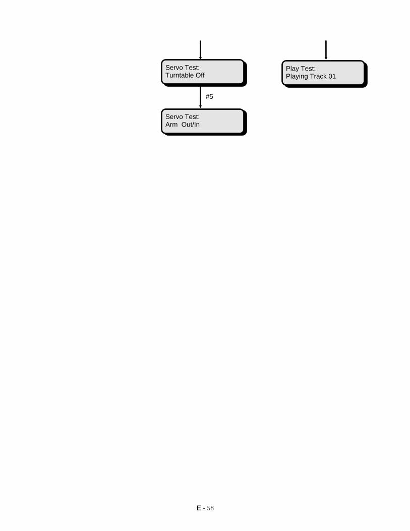
E - 58
#5
Servo Test: Turntable Off
Servo Test: Arm Out/In
Play Test: Playing Track 01

E - 59
AUTO TEST HITS HITS HITS RT MENU HITS RT MENU RT MENU RT MENU RT MENU
SETUP MODE Auto Test
AUTO TEST 150 Run Auto Test
AUTO TEST 150 Test Hours 00
Keyboard Test: No Key Pressed
AAAAAAAAAAAAAAAA AAAAAAAAAAAAAAAA
Pages Test: Turning Pages…
Mechanism Test: Short Test 00**
AUTO TEST 151 View Report
AUTO TEST 154 Start 12/25 16:10
AUTO TEST 155 Stop 12/25 16:25
AUTO TEST 156 Elapsed 000:15
AUTO TEST 150 Test Hours XX
Enter the desired number of hours and press HITS to start the test. 00 is continuous test

E - 60
HITS RT MENU RT MENU HITS RT MENU RT MENU HITS RT MENU RT MENU RT MENU HITS HITS
AUTO TEST 157 View Kybd Errors
AUTO TEST 153 Clear Report
AUTO TEST 157 K06 12/25 16:11
AUTO TEST 153 Are You Sure?
AUTO TEST 157 End Kybd Errors
AUTO TEST 153 Action Done
AUTO TEST 158 View Mech Errors
AUTO TEST 158 M04 12/25 16:15
AUTO TEST 158 End Mech Errors
AUTO TEST 159 View Page Errors
AUTO TEST 159 P02 12/25 16:20
AUTO TEST 159 End Page Errors AUTO TEST 160
View Wlbx Errors
AUTO TEST 152 Print Report
AUTO TEST 152 Printing...

E - 61
TCM SETUP
HITS If Prog and HITS If Yes and HITS RT MENU RT MENU RT MENU RT MENU RT MENU HITS HITS
SETUP MODE TCM Setup
TCM SETUP 170 Recv Calls No/Yes/Prog
TCM SETUP 170 Day None/Every/SMTWTFS
TCM SETUP 170 Start Time 00:00 - 23:59
TCM SETUP 170 Stop Time 00:00 - 23:59
TCM SETUP 170 Num. of Rings 01-99
TCM SETUP 170 Clear Settings
TCM SETUP 170 Are You Sure?
TCM SETUP 170 Action Done

E - 62
TCM SETUP 171 Call Office No/Yes
TCM SETUP 171 Day None/Every/SMTWTFS
TCM SETUP 171 Start Time 00:00 - 23:59
TCM SETUP 171 Stop Time 00:00 - 23:59
TCM SETUP 171 Enter Phone Number
TCM SETUP 171 Retries 01- 99
‘0’
If Yes
RT MENU RT MENU
RT MENU
RT MENU
TCM SETUP 171 Clear Settings
RT MENU
RT MENU
RT MENU
RT MENU
TCM SETUP 171 Are You Sure?
TCM SETUP 171 Action Done

E - 63
TCM SETUP 172 Call if Prob No/Yes
TCM SETUP 172 Enter Pager Nmbr
‘0’
TCM SETUP 172 Enter Pager Sufx
‘0‘
TCM SETUP 172 Pages to Send 1 - 9
TCM SETUP 172 Rprt DBA Jam No/Yes/Pgr/Ofc
TCM SETUP 172 Rprt Ftl Err No/Yes/Pgr/Ofc
TCM SETUP 172 Rprt CD Errs No/Yes/Pgr/Ofc
TCM SETUP 172 Clear Settings
TCM SETUP 172 Are You Sure?
TCM SETUP 172 Action Done
TCM SETUP 172 Rprt Brk In No/Yes/Pgr/Ofc
If Yes
RT MENU
HITS
HITS
RT MENU
RT MENU
RT MENU
RT MENU
RT MENU
RT MENU
RT MENU
RT MENU
RT MENU

E - 64
*Details regarding initialization strings can be found in your modem owners manual. If user defined* HITS Choose from: Rock-Ola
Zoom V3.4 Rockwell 14.4 US Robotics 28.8
User Defined*
TCM SETUP 175 Modem* XXXXXXXXXX
TCM SETUP 175 Enter Xmit Inits*
Enter your modem Xmit Init String. See instructions for entering Custom Message.
TCM SETUP 175 Enter Recv Inits
Enter your modem Recv Init String. See instructions for entering Custom Message.
RT MENU
HITS
TCM SETUP 176 Telecom PW 0000
RT MENU
TCM SETUP 177 Reset Telecom ID
TCM SETUP 177 Are You Sure?
TCM SETUP 177 Action Done
RT MENU
HITS HITS

E - 65
AMP SETUP
SETUP MODE Amp Setup
AMP SETUP 210 Internal Amp
RT PAGES
AMP SETUP 213 Int Tone EQ Join or L/R
HITS
INT * BOTH LOW | | | | | | | HIGH
AMP SETUP 213 Int Tone EQ Join
If Join HITS
HITSTo Adjust EQ –
Use L or R Pages to Move Asterisk
#1 Increases #2 Decreases
AMP SETUP 213 Int Left EQ
If L/R HITS
AMP SETUP 213 Int Right EQ
INT * LEFT LOW | | | | | | | HIGH
RT PAGES
INT * RIGHT LOW | | | | | | | HIGH
HITS
HITS
AMP SETUP 214 Int Balance
INT BAL LT . . . | . . . RT
HITS
Use L or R Pages Buttons To Change Balance
AMP SETUP 215 Int MLWP
AMP SETUP 218 Int LT MLWP 50%
AMP SETUP 219 Int RT MLWP 50%
HITS
RT PAGES
AMP SETUP 216 Int Loudness
RT PAGES
RT PAGES
RT PAGES
AMP SETUP 220 Int LT Loud Off/On
HITS
RT PAGES
RT PAGES
RT PAGES
See Section D of this manual for detailed amplifier operation and programming
information.
AMP SETUP 221 Int RT Loud Off/On

E - 66
AMP SETUP 211 External Amp
AMP SETUP 222 Ext Tone EQ Join or L/R
AMP SETUP 222 Ext Tone EQ Join
EXT * BOTH LOW | | | | | | | HIGH
AMP SETUP 222 Ext Left EQ
EXT * LEFT LOW | | | | | | | HIGH
AMP SETUP 222 Ext Right EQ
EXT * RIGHTLOW | | | | | | | HIGH
AMP SETUP 223 Ext Balance
EXT BAL LT . . . | . . . RT
AMP SETUP 224 Ext MLWP
AMP SETUP 217 Are You Sure?
AMP SETUP 217 Action Done
HITS
AMP SETUP 227 Ext LT MLWP 50%
AMP SETUP 228 Ext RT MLWP 50%
HITS If Join HITS
If L/R HITS HITSTo Adjust EQ –
Use L or R Pages to Move Asterisk
#1 Increases #2 Decreases
HITS
HITS
Use L or R Pages Buttons To Change Balance
HITS
RT PAGES
RT PAGES
HITS
RT PAGES
RT PAGES
RT PAGES
RT PAGES
AMP SETUP 231 Int AVC
AMP SETUP 217 Reset Int Amp
HITS
AMP SETUP 231 Int AVC Off/On
HITS
AMP SETUP 212 Page Decay 02-99
RT PAGES

E - 67
AMP SETUP 225 Ext Loudness
AMP SETUP 226 Reset Ext Amp
AMP SETUP 229 Ext LT Loud Off/On
AMP SETUP 230 Ext RT Loud Off/On
AMP SETUP 226 Are You Sure?
AMP SETUP 226 Action Done
RT PAGES
HITS
RT PAGES
HITS
HITS
AMP SETUP 232 Ext AVC
AMP SETUP 232 Ext AVC Off/On
HITS
RT PAGES
Section
F
Routine Service
- Accounting and Disc Changing- Appearance & Preventative Maintenance- Checking for Errors
F - 1

Section F Routine Service
Rock-Ola Mfg. Corp. Operation and Service ManualDigital CD Nostalgic Models
F - 2
Accounting and DiscChangingThis section is intended to familiarize you withthe data the SyberSonic Electronics system pro-vides. When used properly, this data will giveyou the information you need to be able tomaximize the income potential of your Rock-OlaJukebox.
Also included in this section are instructions forusing Rock-Ola’s exclusive automatic discchanging feature. Appearance and preventativemaintenance considerations are also discussed.
Accounting and PopularityRock-Ola’s SyberSonic Operating System hasmany accounting and popularity features.These include basic and detailed accountingdata along with disc popularity data that can beconfigured to be viewed and/or printed in leastpopular, most popular or in magazine order.
This section will define and discuss the use ofaudit and popularity data. See Section E foraccess instructions and a graphical representa-tion of the Accounting and Popularity Features.
Accounting
90 Last Reset - This is the date and time theperiod to date audit data was last reset.This data can be used to calculate the num-ber of days that have passed since the lastaudits were done.
91 Print Accounting Data - This featurecauses the accounting data to be “sent” tothe SyberSonic’s IR printer port for use withthe optional Data Printer Kit. (Rock-Ola partnumber 02377-01). See your distributor fordetails on the Data Printer Kit.
92 Basic Accounting - Simple readoutsshowing selections, plays and cash. Thisdata is broken down into resettable period todate (Ptd) and non-resettable Total figures.The data is as follows:
Total Selections: This figure is the numberof selections made over the lifetime of thejukebox. Non-resettable.
Ptd Selections - This figure is the numberof selections made since the last reset. Re-settable.
Total Plays - This figure is the number ofsongs played over the lifetime of the juke-box. Non-resettable. The difference be-tween the songs selected and the songsplayed is the amount of overplay.
Ptd Plays - Number of songs played sincethe last reset. Resettable. The differencebetween the songs selected and the songsplayed is the amount of overplay.
Total Cash - The amount of money inserted(bills and coins) into the jukebox over thelifetime of the machine. Non-resettable.
Ptd Cash - The amount of money (bills andcoins) inserted into the jukebox since thelast reset. Resettable.
93 Total Accounting - Detailed readoutsshowing resettable (Ptd) and non-resettable(Total) figures for selections, plays and cashbroken down by source. Sources includethe jukebox keyboard, wallboxes and re-mote control.
Total Selections: Number of selectionsmade from all sources over the lifetime ofthe jukebox. Non-resettable.
Ptd Selections - Number of selectionsmade from all sources since the last reset.Resettable.
Total Local Norm - Number of “normal”selections made via the jukebox keyboardover the lifetime of the machine. Non-resettable.
Ptd Local Norm - Number of “normal” se-lections made via the jukebox keyboardsince the last reset. Resettable.
Total Local Spec - Number of “special” se-lections made via the jukebox keyboard overthe lifetime of the machine. (For definition of“special”, see Quick Find #13 and #63 in theQuick Find Reference Programming Defini-tions section). Non-resettable.
Ptd Local Spec - Number of “special” se-lections made via the jukebox keyboardsince the last reset. Resettable

Section F Routine Service
Rock-Ola Mfg. Corp. Operation and Service ManualDigital CD Nostalgic Models
F - 3
Total Wallbox Normal - Number of normalselections made via all wallboxes over thelifetime of the jukebox to which the wall-boxes are connected. Non-resettable
Ptd Wallbox Normal - Number of normalselections made via all wallboxes since thelast reset of the machine to which the wall-boxes are connected. Resettable.
Total Wallbox Spec - Number of “special”selections made via all wallboxes over thelifetime of the jukebox to which the wall-boxes are connected. Non-resettable
Ptd Wallbox Spec - Number of “special”selections made via all wallboxes since thelast reset of the machine to which the wall-boxes are connected. Resettable
Wallbox Detail - The amount of cash (coinsand bills) inserted into wallboxes connectedto the main jukebox.
Total Wallbox Cash - The total amountof cash inserted into wallboxes con-nected to the main jukebox over the life-time of the main jukebox. Non-resetta-ble.
PTD Wallbox Cash - The amount ofcash inserted into wallboxes connectedto the main jukebox since the last timethe cash audits were reset. Resettable.
Total Cash - The amount of money (billsand coins) inserted into the jukebox over thelifetime of the machine. Non-resettable.
Ptd Cash - The amount of money (bills andcoins) inserted into the jukebox since its lastreset. Resettable.
Ptd Coin Inputs - This choice breaks downthe money inserted into the jukebox by de-nomination as defined by the coin input set-tings. (See the definition for Quick Find #61for details). Resettable.
Ptd Coin Input 1 - The amount of cashinserted as sensed by coin input 1.
Ptd Coin Input 2 - The amount of cashinserted as sensed by coin input 2.
Ptd Coin Input 3 - The amount of cashinserted as sensed by coin input 3.
Ptd Coin Input 4 - The amount of cashinserted as sensed by coin input 4.
Ptd Coin Input 5 - The amount of cashinserted as sensed by coin input 5. Inthe United States, this is the figure forthe amount of money in quarters thathas been inserted into the jukebox.
Ptd Coin Input 6 - The amount of cashinserted as sensed by coin input 6. Inthe United States, this is the amount ofmoney in bills ($1 & $5) that has beeninserted into the jukebox.
Total Free Sel. - Number of selections thathave been made for free over the lifetime ofthe jukebox. Non-resettable.
Ptd Free Sel. - Number of selections thathave been made for free since the last re-set. Resettable.
Total Free Pct - The percentage of all se-lections made that were made for free overthe lifetime of the jukebox. Non-resettable.
Ptd Free Pct - The percentage of all selec-tions made that were made for free sincethe last reset. Resettable.
Free Detail - Detailed information about thesource and type of free plays. Resettable.
Free Keyboard Norm - Number of free“normal” selections made via the juke-box keyboard.
Free Keyboard Spec. - Number of free“special” selections made via the juke-box keyboard.
Free Remote Norm - Number of free“normal” selections made via the IR re-mote control.
Free Remote Spec. - Number of free“special” selections made via the IR re-mote control.
Timed Bonus Norm - Number of free“normal selections” made during thetimed bonus period.
Timed Bonus Spcl - Number of free“special” selections made during thetimed bonus period.

Section F Routine Service
Rock-Ola Mfg. Corp. Operation and Service ManualDigital CD Nostalgic Models
F - 4
Self Play Select - Number of selectionsmade via the jukeboxes “self-play” fea-tures.
Total Album Buys - Number of times a fullalbum was selected (by typing 00 after en-tering the album number) over the lifetime ofthe jukebox. Non-resettable.
Ptd Album Buys - Number of times a fullalbum was selected (by typing 00 after en-tering the album number) since the last re-set. Resettable.
Total Plays - Number of songs played overthe lifetime of the machine. Non-resettable.
Ptd Plays - Number of songs played sincethe last reset. Resettable.
Total Play Ratio - The ratio of songs se-lected versus the number of songs actuallyplayed over the lifetime of the machine.This ratio is the “overplay” ratio. The higherthis ratio, the more the overplay is. Non-resettable.
Ptd Play Ratio - The ratio of songs selectedversus the number of songs actually playedsince the last reset. This ratio is the “over-play” ratio. The higher this ratio, the morethe overplay is. Resettable.
Total Average Price (Paid Play) - The cal-culated average price per song based onpaid play only over the lifetime of the ma-chine. Non-resettable.
Ptd Average Price (Paid Play) - The cal-culated average price per song based onpaid play only since the last reset. Resetta-ble.
Total Average Price (Play) - The calculatedaverage price per song based on paid andfree play over the lifetime of the machine.Non-resettable.
Ptd Average Price (Play) - The calculatedaverage price per song based on paid andfree play since the last reset. Resettable.
94 Clear Ptds - Clears all period to date auditfigures. Use this feature only after all de-sired data has been retrieved.
95 View Level 1 - Allows the audit data to beviewed (but not cleared) while the machine
is in security level 1. See the explanationfor Quick Find #95 in the Quick Find Refer-ence Programming Definitions found insection E of this manual.
96 SP “Self Plays” - If Yes, self plays areincluded in the the free percentage cal-culations. Total Free Pct and Ptd FreePct on prior page.
97 Power Cycles - Displays the date, timeand if the jukebox power was cycled on oroff. A sample display is:10/30 10:06 1which indicates the jukebox power wasturned on at 10:06AM on October 30.Another sample is:10/31 02:05 0which indicates the jukebox power wasturned off at 2:05AM on October 31.
Popularity
Popularity data compiled by the SyberSonicElectronics system provides you with the infor-mation necessary to determine what music is“working” (and not working) at the location inwhich the jukebox is installed. When used pro-perly, this data will ensure that your jukeboxnever has any “stale” music installed.
100 Last Reset - The date and time thepopularity was last reset. This informationallows you to calculate the amount of timethe popularity figures have had to accu-mulate. It is a good idea to reset thepopularity data when a disc(s) have beenchanged in order to build new popularitydata based upon the “new” CDs.
101 View Pop. - Select the direction you wantto view the popularity. (To read the popu-larity data, use Quick Find 103). Choicesare:
Least - View the disc popularity in as-cending order from the least played CD tothe most played CD.
Most - View the popularity in descendingorder from the most played CD to the leastplayed CD.
Order - View the popularity by slot num-ber beginning with slot 00. Can also beused with the automatic disc changing

Section F Routine Service
Rock-Ola Mfg. Corp. Operation and Service ManualDigital CD Nostalgic Models
F - 5
feature for the initial loading of the CD’s.(For ease of use of the Automatic DiscChanging feature, we recommendleaving this feature set to Least afterthe discs have been loaded).Default Least.
102 Print Popularity - Sends the popularitydata to the IR data port on the computerfor use with Rock-Ola Data Printer Kit #02977-01 (optional).
103 View Pop. Data - View the popularitydata in the order based upon the setting inQuick Find 101. The automatic discchanging feature is also accessed fromthis menu. See the Disc Changing sectionbelow for a full explanation of the use ofthe automatic disc changing feature.
104 Clear Pop. Data - Clears all the popu-larity data. Use only after the desired datahas been retrieved and any new discshave been installed.
Disc ChangingRock-Ola’s SyberSonic Jukebox will furtherenhance income with its capability of auto-matically selecting and providing an easymethod for changing a disc. Using its advancedmicroprocessor technology, the machine willautomatically display the least played CD (theone that should be changed... you don’t wantstale music in the jukebox!), and move thepages to the corresponding number so thealbum jacket and title strip can be changed. Thejukebox will “remember” the disc number justchanged so that it can be automatically mappedwhen the machine is returned to normal service.
It is best to load or change discs when the C21Mechanism is idle (no disc in play and the liftarm down). The tower must not be moved byhand. With power on, the lift cannot be pulled upby hand. If loading is done with power off, caremust be taken to leave the arm down. If discsare changed with the unit in play, extra caremust be taken to not install a disc into the slotthe CD in play came from.
Here’s how to use this exclusive feature:
1. Make sure View CD Order (Quick Find 101)is set to “View Least Pop”. Access Quick
Find 103. (View Pop Data in the PopularityMenu.)
2. Press Hits. The SyberSonic computer willnow sort the popularity data. When finishedsorting, the least played CD number alongwith the number of times its played will beshown on the display.
3. Press #1 Button. The title pages will moveto the corresponding position and the discwill be loaded on the player.
4. Remove the old CD and install the new CDon the player. Change the album cover andtitle strip.
5. Press #2 Button to have the jukebox put theCD away and “remember” the new CD formapping.
To change another CD, press the Right MenuButton to view the next least popular disc and dosteps 3 through 5 again.
• If for some reason the automaticallyselected CD is not the one you want tochange (maybe an “all occasion” disc),simply press the Right Menu button again.Then do steps 3 through 5.
When finished changing CDs, put the machineback into the Normal Mode. It will automaticallymap the just changed discs.
Appearance and Preventa-tive MaintenanceAppearance
Over time, many operators have learned thatone of the easiest ways to maintain maximumincome from their jukeboxes is to simply keepthem clean. We at Rock-Ola agree. That is thereason we designed the cabinet and exposedareas so that not only are they attractive andeye catching, cleaning them are fast and easy.
It is strongly recommended that at every routineservice, the cabinet, glass and mechanism becleaned. See Recommended Cleaning Suppliesand Lubricants in Section G for a list of cleaningsupplies.
It is also very important to make sure all of thelights, color wheels and animation features are

Section F Routine Service
Rock-Ola Mfg. Corp. Operation and Service ManualDigital CD Nostalgic Models
F - 6
working. These should be checked at each rou-tine service.
Preventative MaintenanceRock-Ola SyberSonic Jukeboxes are designedand manufactured to provide years of troublefree operation. As with any mechanical device,some routine maintenance is required. However,SyberSonic Jukeboxes require very little. Basi-cally, all that is necessary is to keep it clean andoccasionally check a few adjustments.
Detailed preventative maintenance considera-tions can be found in Section G of this manual.
Checking For ErrorsFinally, one last thing to consider during routineservice is to check the machine for proper ope-ration.
Occasionally, as with anything mechanical, amalfunction may have occurred that for somereason the location did not communicate to you.In order to prevent the machine’s income fromsuffering due to unreported malfunctions, theSyberSonic system has built-in diagnostic anderror reporting features.
Sections G and H of this manual contain de-tailed maintenance and troubleshooting infor-mation.
It is recommended that the “error codes” bechecked at every routine service. If any exist,the cause should be investigated and correctedas soon as possible. Many times a minor prob-lem which can be easily corrected is ignored.That minor problem then becomes a majorproblem which should have never happened.Protect your income. Let the machine work foryou. Use its features to your advantage.

Section
G
Maintenance
- General Maintenance Considerations- Preventative Maintenance- Mechanical Adjustments- Coin Mechanism Cleaning- Replacing Fluorescent Lamps
G - 1

Section G Maintenance
Rock-Ola Mfg. Corp. Operation and Service ManualDigital CD Nostalgic Models
G - 2
MaintenanceThis section contains information about main-taining your Rock-Ola SyberSonic Jukebox. Itcovers general maintenance, preventativemaintenance, mechanical adjustments, lubrica-tion and cleaning.
We strongly recommend that you contactyour Dealer/Distributors Service Departmentfor guidance before attempting any mainte-nance/repair task that you are not thoroughlyfamiliar with.
General MaintenanceConsiderationsTools and Equipment
In order to properly maintain and repair the Sy-berSonic Jukebox, it is necessary to posses thecorrect tools and equipment. Following is a listof the basic tools and equipment recommendedby Rock-Ola. This list contains only the itemsnecessary to perform basic maintenance, trou-bleshooting and repair tasks. Other, more spe-cialized, tools and equipment are necessary toperform more complex tasks.
• Nut Driver Set (3/16” through 1/2”)• 1/4” Slotted Screwdriver• # 2 Phillips Screwdriver• Long Nose Pliers• Small Diagonal Cutters• 1/4” Open End Wrench• 3/8” Open End Wrench• 1/2” Open End Wrench• 6” Adjustable Wrench• Volt/Ohm Meter with at least 20,000
Ohms per Volt impedance
Cleaning Supplies and Lubricants
One of the most important factors in properlymaintaining any equipment is keeping it cleanand lubricated. The Rock-Ola SyberSonicJukebox is no different. We recommend thefollowing supplies be carried and used at anytime the jukebox is serviced.
• Ammoniated Glass Cleaner• Spray Furniture Wax• Mild Detergent Solution• Isopropanol Alcohol (25%)
• Lint Free Cotton Swabs• Lint Free Wiping Cloth• 1½” Paint Brush (For Dusting)• Light Machine Oil• White Grease
Spare Parts
Although the Rock-Ola SyberSonic Jukebox hasproven to be one of the most reliable machineson the market, occasionally malfunctions do oc-cur. Most of the time, the problem can be easilycorrected with a simple adjustment or cleaning.However, the malfunction may be caused by acomponent which has failed. In order to preventa loss of income due to a component failure, werecommend the following items be carried asspares. This list is recommended for 5 or moremachines.
• 02451 Serviceman’s Kit Includes CPU, Amplifier
Boards and Fuses• 55941-A DC Gear Motor Assy.• 58687-A Mech Opto Cable Assy.• 59241-2A CD Player Assembly• 57335 Coin Acceptor, U.S.
Quarter (Other countries, your local coin acceptor)
Preventative MaintenanceIn order to keep your Rock-Ola SyberSonicJukebox running like new for many years, anoccasional preventative maintenance routine isrecommended.
The frequency at which the routine needs to beperformed will vary based upon your local con-ditions, but we recommend an interval of ap-proximately three months. A few minutes spenton preventative maintenance will not only savemany hours of “down time”, it will help increasecustomer confidence.
This routine is basically a simple “clean up” andchecking the mechanism index adjustment.
The Preventative Maintenance Routine is asfollows:
• Check for errors. If any exist, investigateand correct the cause. See “Viewing ErrorCodes” in Section H for detailed instructions.

Section G Maintenance
Rock-Ola Mfg. Corp. Operation and Service ManualDigital CD Nostalgic Models
G - 3
• Clean all dust and dirt from inside of cabinetand from mechanism.
• Clean All CDs. Several influences from the
outside can make a disc dirty.
• Easy to remove are: smoke, dust & fin-ger prints. These can be cleaned with asoft, lint free cloth soaked in a solutionof water and detergent. Wipe from theinside toward the outside and not in acircular motion !! Rinse well and dryup with a dry soft, lint free cloth.
• Minor scratches can be removed with asoft, lint free cloth and a soft polish.
Figure 1G - Compact Disc
• Clean the laser eye.
WARNINGActuator is very fragile. Lens is made ofspecial material with a coating, do notscratch or damage. Clean carefully.
ADVERTENCIAEl Actuator es muy frágile. Su lente está hecho deun material especial cubierto por un film, no rayarní dañar. Limpiar cuidadosamente.
AVERTISSEMENTL’actionneur est très fragile. La lentille est fabri-quée avec une matière spéciale enduite d’unrevêtement. Faites attention de ne pas le rayer oul’endommager. Nettoyez avec soin.
The CD player is extremely sensitiveto static discharges. Always groundyourself before touching the playerand never touch the eye. The CD
player itself has no adjustments. The only mainte-nance required is occasional lens cleaning.
Los Toca-discos CD son extremamente sensitivosa descargas de electricidad estatica. Siemprehaga “tierra” antes de tocar el Toca-discos CD, ynunca toque el ojo (lente). El Toca-discos en sí,
no tiene ajustes. El único mantenimiento re-querido es el limpiar el ojo ocasionalmente.
Le lecteur de disque compact est extrêmementsensible aux décharges statiques. Veuillez tou-jours vous mettre à la masse avant d’y toucher etne touchez jamais à l’oeil. Le lecteur de disquecompact ne présente aucun réglage. Le seul en-tretien nécessaire est un nettoyage régulier de lalentille.
• Moisten a clean Q-tip with a solution of 25%Isopropanol (IPA). Place the tip on the lensand press down carefully. Wipe carefully inthe direction (perpendicular to the sledge di-rection) so that the actuator doesn’t move.Dry up with a clean, dry Q-tip.
Figure 2G - CD Player
• Clean the Bill Validator (if installed) followingthe validator manufacturer’s recommenda-tions.
• Clean the coin acceptor using a mild deter-gent solution. Be sure to thoroughly drybefore re-installing.
• Clean all glass inside and out. Clean and
polish outside of cabinet.
Mechanical Adjustments The mechanism adjustments are inter-related. Ifthe magazine motor, opto sensor, or controlboard is replaced, the adjustments should bechecked. Read the instructions carefully beforeattempting the adjustments.
The CD player is extremely sensitiveto static discharges. Always groundyourself before touching the playerand never touch the eye.
El Toca-discos CD es extremamente sensitivo adescargas de electricidad estática. Siempre toque“tierra” antes de tocar el Toca-discos, y nuncatoque el ojo (lente).

Section G Maintenance
Rock-Ola Mfg. Corp. Operation and Service ManualDigital CD Nostalgic Models
G - 4
Le lecteur de disque compact est extrêmementsensible aux décharges statiques. Veuillez tou-jours vous mettre à la masse avant d’y toucher etne touchez jamais à l’oeil.
The CD player is not user serviceable. The onlymaintenance required is occasional lens clean-ing.
Cleaning instructions can be found in the “Pre-ventative Maintenance” section.
Magazine AdjustmentsAny adjustment made will change the settings ofthose following. Always check the indexing ifany magazine adjustment is made.
Magazine Band Adjustment
WARNINGAdjust band with the magazine empty.
ADVERTENCIAAjustar banda con el magazine vacío.
AVERTISSEMENTNe réglez la bande que lorsque le magasin est vide.
Loosen adjustment screws to obtain approx.1/32” gap between the magazine wire and theband. Re-tighten the screws. (Fig. 3G).
Figure 3G - Magazine Band Adjustment
Gripper Rest Adjustment
Rotate the magazine until the inner gripper “V” iscentered between two magazine separatorwires. Adjust the gripper rest bracket so thegripper arm tip is centered between the wiresand falls freely into the rest slot. (Fig. 4G).
Figure 4G - Gripper Rest Adjustment
Magazine Motor Gear Mesh Adjustment
Magazine rotational play must be less than1/16”. If the play exceeds 1/16”, loosen the ma-gazine motor and slide it toward the magazinegear.
Figure 5G - Magazine Motor Gear
Magazine Indexing Adjustment
WARNINGInsert damaged discs in slots 00, 01, 49, 50,98, 99 or leave empty.
ADVERTENCIAInsertar discos dañados en compartimentos 00,01, 49, 50, 98, 99 o dejar vacíos.
AVERTISSEMENTInsérez les disques endommagés dans les fentes00, 01, 49, 50, 98, 99 ou laissez vide.

Section G Maintenance
Rock-Ola Mfg. Corp. Operation and Service ManualDigital CD Nostalgic Models
G - 5
Run Index Test (Quick Find #145): If the CDis not being gripped exactly between the maga-zine wires, the indexing needs to be adjusted.Loosen screw “A” and turn screw “B” clockwiseif the magazine stops too soon or counter-clockwise if it stops too late. Re-tighten screw“A” and test all 6 positions after adjusting.
Figure 6G - Magazine Indexing Adjustment
Lubricating of Gripper Unit
1. Push on inner gripper #1 to expose pin #2.2. Remove pin #2.3. Remove inner gripper #1, spring #3, and
reversing assembly #4.4. Remove cam #5.5. Scribe gear #6 and gear #7 so they can be
replaced the same way.6. Remove gear #6.7. Wash all parts and the gripper housing in a
solvent suitable for removing all old lubri-cant.
8. Re-lubricate all moving parts at their matingpoints with a light coat of white grease,Rock-Ola part number ST-09126 or equiv.
9. Re-install parts in reverse order.
Figure 7G - Gripper Assembly
CD Player Adjustments
The CD player is extremely sensitiveto static discharges. Always groundyourself before touching the playerand never touch the eye. The CD
player itself has no adjustments. The only mainte-nance required is occasional lens cleaning. Thereare no electronic adjustments on the CD player.
El Toca-discos CD es extremamente sensitivo adescargas de electricidad estática. Siempre toque“tierra” antes de tocar el Toca-discos y nuncatoque el ojo (lente). El Toca-discos CD no tieneajustes en sí. El único mantenimiento requeridoes el limpiar el ojo ocasionalmente. El Toca-discos CD no tiene ajustes electrónicos.
Le lecteur de disque compact est extrêmementsensible aux décharges statiques. Veuillez tou-jours vous mettre à la masse avant d’y toucher etne touchez jamais à l’oeil. Le lecteur de disquecompact ne présente aucun réglage. Le seul en-tretien nécessaire est un nettoyage régulier de lalentille. Le lecteur CD ne présente aucun réglageélectronique.
CD Player Centering Adjustment
Select a disc. Turn the power switch off justbefore the CD is set on the turntable. If the holein the disc is not centered over the turntablehub, loosen the 4 mounting screws (A) and re-position the player. Tighten the screws and testagain.
Clamper Plate Height Adjustment
Select a disc. Turn the power switch off whenthe transfer cycle is finished. The magnet(shaded) should be centered within the clamperplate as shown in the diagram. Turn screw (B)as required to make the adjustment.
A
B

Section G Maintenance
Rock-Ola Mfg. Corp. Operation and Service ManualDigital CD Nostalgic Models
G - 6
Figure 8G - CD Player and Clamper Plate
Title Display AdjustmentRock-Ola’s Legend and Rocket models utilize atitle display assembly that has only one adjust-ment.
The opto assembly mounted at the top of thedisplay assembly controls when the drive motorstops for each turn of the page.
Move the opto assembly (A) to the left or to theright until the pages seat against the previousone during a page turning cycle. Run the pagesin both directions to ensure they seat properly.
Coin Mechanism CleaningThe coin mechanism cleaning procedure willdepend on which type of coin mechanism is ins-talled.
If an electric or electronic device is installed,follow the coin mechanism’s manufacturerscleaning recommendations.
If a standard mechanical coin mechanism is in-stalled, the following procedure can be followed.
Remove coin acceptor from its mountingbracket.
Using a soft brush, a mild detergent andwater, thoroughly clean all surfaces of the
coin acceptor making sure to remove all dirtand deposits.
Thoroughly rinse and dry coin acceptor.
Install coin acceptor back into its mountingbracket and test.
Replacing FluorescentLamps
CAUTIONThe jukebox utilizes an electronicballast to power the lamps. Alwaysdisconnect the power to the lighting
when replacing lamps. Failure to do so may resultin a shock hazard and/or damage to the ballast.
PRECAUCIÓN:La rocola utiliza un estabilizador electrónico paraenergizar las lámparas. Siempre desconecte laenergía al sistema de iluminación cuando cambielas lámparas. Si no lo hace puede sufrir unadescarga eléctrica y/o causar daños alestabilizador.
MISE EN GARDE :Pour allumer les lumières, le juke-box fait appel àun ballast électronique. Veillez à toujours couperle courant électrique alimentant l’éclairage avantde remplacer une ampoule. Le non-respect decette précaution pourrait présenter un risqued’électrocution ou de dommages au ballast.
Turn the power to the jukebox off via themain switch on the poewr entry module(Corcom).
Open the door and unplug the ballast fromthe power supply “Lighting” socket (J8).
The lamps can be removed and replacedwithout tools. Squeeze the lamp in thecenter of the color cylinder tube and rotate90°. Pull the lamp out of the socket ends.Slide the lamp out of the tube and replace.Insert the tube into the socket ends and ro-tate 90°. Be sure cylinder gears engagewith the motor gear.
Replace the ballast connector into J8 on thepower supply.
Turn the main switch back on.
Figure 9G - Title Display
A

Section
H
Troubleshootingand Repair
- Troubleshooting and Repair Overview- Troubleshooting Charts- Fuse and LED Locations- Block Diagrams- Start up and Diagnostic Mode Operation- Test Mode- Viewing Error Codes- Using Error Codes- Running Tests- Amplifier Troubleshooting
H - 1

Section H Troubleshooting and Repair
Rock-Ola® Mfg. Corp Operation and Service Manual Digital CD Nostalgic Models
H - 2
Troubleshooting and Repair Overview The SyberSonic Electronics System puts today’s latest technology to work for you. It can assist you in troubleshooting tasks by providing com-prehensive Input/Output Tests for the Control Computer, Keyboard and Display, and a testing utility for the Mechanism and Title Pages. If an error occurs during normal operation, the Rock-Ola Control Computer will store an error code and then automatically remind you to check for error codes whenever the lid/door is opened. We recommend that before beginning any trou-bleshooting or repair task that you thoroughly familiarize yourself with this section, along with sections E and G of this manual. If anything is still not clear, contact your dealer/distributor for assistance. Information available in this section includes: • Troubleshooting Charts • Fuse And LED Locations • Block Diagrams • Start Up and Diagnostic Mode Operation • Test Mode Operation which includes read-
ing error codes, error code charts and running tests.
Working With the Tools You’ve Got Section G of this manual outlined the minimum tools and equipment necessary to properly ser-vice the Rock-Ola SyberSonic Jukebox. One set of tools it didn’t mention were the tools you carry with you all the time... your senses and your common sense. When a malfunction occurs, the first thing you need to do is evaluate what the symptoms really are. This is where common sense comes in. A common service call is, “I put money in the machine and got nothing for it.” Where do you begin? The Bill Acceptor? The Coin Acceptor? The CD Player? The Mecha-nism? The Amplifier?
All of those components can cause the above statement to be made. But what are the real symptoms? As far as the patron is concerned, the above statement is all that needs to be said for you to be able to know what’s wrong. Unfortunately, that simply is not the case. You need more in-formation. You need to ask questions. Things like: • “When you put your money into the ma-
chine, did it give you credits?” • “Did you use bills or coins?” • “How much money did you put in?” • “How many credits did you get?” • “Did the machine allow you to make selec-
tions?” • “Did you hear any of the songs you se-
lected?” • “Did you hear any music at all?” • “Have other patrons had any problems?” The answers given to those questions will de-termine which approach you will take toward solving the problem. For instance, in response to your question, the patron tells you, “I put in a Dollar bill and got no credits, but Joe over there put in 4 quarters and got his music.” Common Sense should immedi-ately tell you that you may have a problem with the Bill Validator. Now let’s say the response to your questioning is, “I made my selections and saw the display showed them playing, but there was no sound.” Totally different symptoms! Now you’re dealing with an audio problem. So ask questions! It is probably the most pow-erful tool you posses. Another set of tools that are often ignored are your senses. Sight, Sound, Smell, Touch. You can see if something is disconnected, hear if something is scraping, smell if something “smoked” or feel if something is vibrating. Use your senses to help isolate the problem to a specific area.
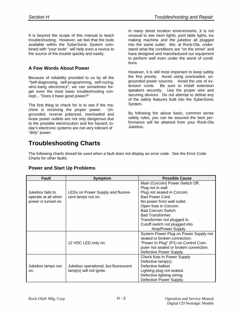
Section H Troubleshooting and Repair
Rock-Ola® Mfg. Corp Operation and Service Manual Digital CD Nostalgic Models
H - 3
It is beyond the scope of this manual to teach troubleshooting. However, we feel that the tools available within the SyberSonic System com-bined with “your tools” will help even a novice to the source of the trouble quickly and easily. A Few Words About Power Because of reliability provided to us by all the “Self-diagnosing, self-programming, self-curing, whiz-bang electronics”, we can sometimes for-get even the most basic troubleshooting con-cept... “Does it have good power?” The first thing to check for is to see if the ma-chine is receiving the proper power. Un-grounded, reverse polarized, overloaded and loose power outlets are not only dangerous due to the possible electrocution and fire hazard; to-day’s electronic systems are not very tolerant of “dirty” power.
In many street location environments, it is not unusual to see neon lights, pool table lights, ice making machine and the jukebox all plugged into the same outlet. We, at Rock-Ola, under-stand what the conditions are “on the street” and have designed and manufactured our equipment to perform well even under the worst of condi-tions. However, it is still most important to keep safety the first priority. Avoid using overloaded, un-grounded power sources. Avoid the use of ex-tension cords. Be sure to install extension speakers securely. Use the proper wire and securing devices. Do not attempt to defeat any of the safety features built into the SyberSonic System. By following the above basic, common sense safety rules, you can be assured the best per-formance will be attained from your Rock-Ola Jukebox.
Troubleshooting Charts The following charts should be used when a fault does not display an error code. See the Error Code Charts for other faults. Power and Start Up Problems
Fault Symptom Possible Cause Jukebox fails to operate at all when power is turned on.
LEDs on Power Supply and fluores-cent lamps not on.
Main (Corcom) Power Switch Off. Plug not in wall. Plug not seated in Corcom. Bad Power Cord. No power from wall outlet. Open fuse in Corcom. Bad Corcom Switch. Bad Transformer. Transformer not plugged in. Cutoff switch not plugged into Amp/Power Supply
12 VDC LED only on.
System Power Plug on Power Supply not seated or broken connection. “Power In Plug” (P1) on Control Com-puter not seated or broken connection. Defective Power Supply.
Jukebox lamps not on.
Jukebox operational, but fluorescent lamp(s) will not ignite.
Check fuse in Power Supply Defective lamp(s). Defective ballast Lighting plug not seated. Defective lighting wiring. Defective Power Supply.
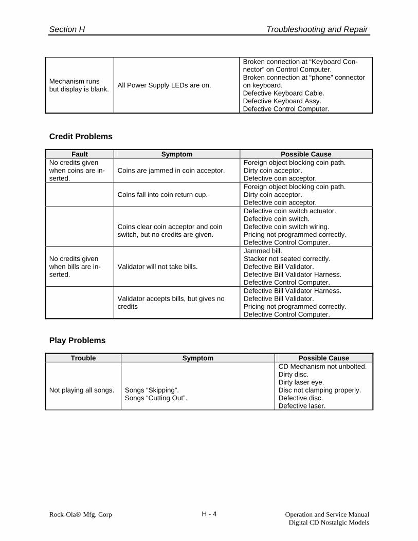
Section H Troubleshooting and Repair
Rock-Ola® Mfg. Corp Operation and Service Manual Digital CD Nostalgic Models
H - 4
Mechanism runs but display is blank. All Power Supply LEDs are on.
Broken connection at “Keyboard Con-nector” on Control Computer. Broken connection at “phone” connector on keyboard. Defective Keyboard Cable. Defective Keyboard Assy. Defective Control Computer.
Credit Problems
Fault Symptom Possible Cause No credits given when coins are in-serted.
Coins are jammed in coin acceptor.
Foreign object blocking coin path. Dirty coin acceptor. Defective coin acceptor.
Coins fall into coin return cup.
Foreign object blocking coin path. Dirty coin acceptor. Defective coin acceptor.
Coins clear coin acceptor and coin switch, but no credits are given.
Defective coin switch actuator. Defective coin switch. Defective coin switch wiring. Pricing not programmed correctly. Defective Control Computer.
No credits given when bills are in-serted.
Validator will not take bills.
Jammed bill. Stacker not seated correctly. Defective Bill Validator. Defective Bill Validator Harness. Defective Control Computer.
Validator accepts bills, but gives no credits
Defective Bill Validator Harness. Defective Bill Validator. Pricing not programmed correctly. Defective Control Computer.
Play Problems
Trouble Symptom Possible Cause Not playing all songs.
Songs “Skipping”. Songs “Cutting Out”.
CD Mechanism not unbolted. Dirty disc. Dirty laser eye. Disc not clamping properly. Defective disc. Defective laser.

Section H Troubleshooting and Repair
Rock-Ola® Mfg. Corp Operation and Service Manual Digital CD Nostalgic Models
H - 5
Mechanism picks up disc then puts it back into the magazine without spinning it.
Disc installed backwards. Dirty disc. Dirty laser eye. Defective disc. Disc not clamping properly. Defective disc. Defective laser. Defective Control Computer.
Mechanism picks up disc, spins it, and then puts it back into the magazine without playing.
Dirty disc. Dirty laser eye. Disc not clamping properly. Defective disc. Defective laser. Defective Control Computer.
Playing wrong songs.
Patron selected a track other than track 1, but the machine played track 1.
Dirty disc. Dirty laser eye. Disc not clamping properly. Defective disc. Defective laser.
Gripper picked up wrong disc.
Indexing adjustment. Dirty Mech Opto Sensor. Defective Mech Opto Sensor. Defective Opto Sensor wiring.
Titles on disc and title strip do not match.
Correct/replace title strip. Replace disc.
Page Problems
Fault Symptom Possible Cause Pages will not turn.
Pages will not turn at all.
Pages not plugged in. Pages harness at computer not seated. Pages not programmed properly. (See Page Options in section E.) Defective pages detent switch. Defective pages motor. Defective computer.
Pages will only turn to a certain point.
Pages not programmed properly. (See Pages Options in section E).
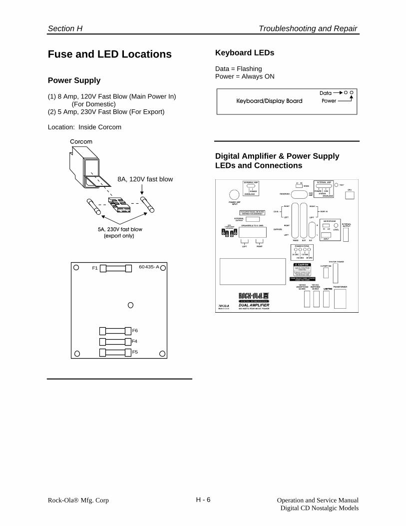
Section H Troubleshooting and Repair
Fuse and LED Locations
Power Supply
(1) 8 Amp, 120V Fast Blow (Main Power In) (For Domestic) (2) 5 Amp, 230V Fast Blow (For Export)
Location: Inside Corcom
Rock-Ola® Mfg. Corp Operation and Service Manual Digital CD Nostalgic Models
H - 6
F1
F6
F4
F5
60435-A
Keyboard LEDs Data = Flashing Power = Always ON
Digital Amplifier & Power Supply LEDs and Connections
8A, 120V fast blow

Section H Troubleshooting and Repair
Block Diagrams
Amplifier Block Diagram
CD IN
FIXEDOUT
LEFT
RIGHT
CD IN
FIXEDOUT
DIGITALSIGNALPROCESSOR(DSP)
DIGITALSIGNAL
U1
BGM INPUT
BGM INPUT
DIGITALSIGNALPROCESSOR(DSP)
U4
MIC INPUTU6A
U5
TO U3
U6B
MIC PREAMP
AUDIODETECTOR
4CHSWITCH
MIXERS
U7B
U7A
VARIABLEOUTPUT
VARIABLEOUTPUT
MIXERS
U8B
U8A
POWER AMPLIFIERMODULE 60442-A
EXTERNALOUTPUT
EXTERNALOUTPUT
FROMU3
U3
U3
AUDIO OUITPUTPANEL 70107-A
MICROPROCESSOR
U3
RS-485TRANS-CEIVER
U2
CPU
CONTROL
LED'S
PRE- AMPMODULE 60441-A
POWER AMPLIFIERMODULE 60442-A
CONTROL
EXTERNAL OUTPUT
12345
12345
INTERNAL OUTPUT
1234
Rock-Ola® Mfg. Corp Operation and Service Manual Digital CD Nostalgic Models
H - 7

Section H Troubleshooting and Repair
CPU Block Diagram
Rock-Ola® Mfg. Corp Operation and Service Manual Digital CD Nostalgic Models
H - 8

Section H Troubleshooting and Repair
CD Start Up Procedure and Run Dia-gram • Laser on • Focus on and find focus • Turntable start • Internal DSICS optimization for radial and
focus. (offset and gain) • Radial tracking • Read table of contents. (start and stop times
of first 21 tracks) • Jump to selected track. (or track 1 if se-
lected track is not found).
Rock-Ola® Mfg. Corp Operation and Service Manual Digital CD Nostalgic Models
H - 9
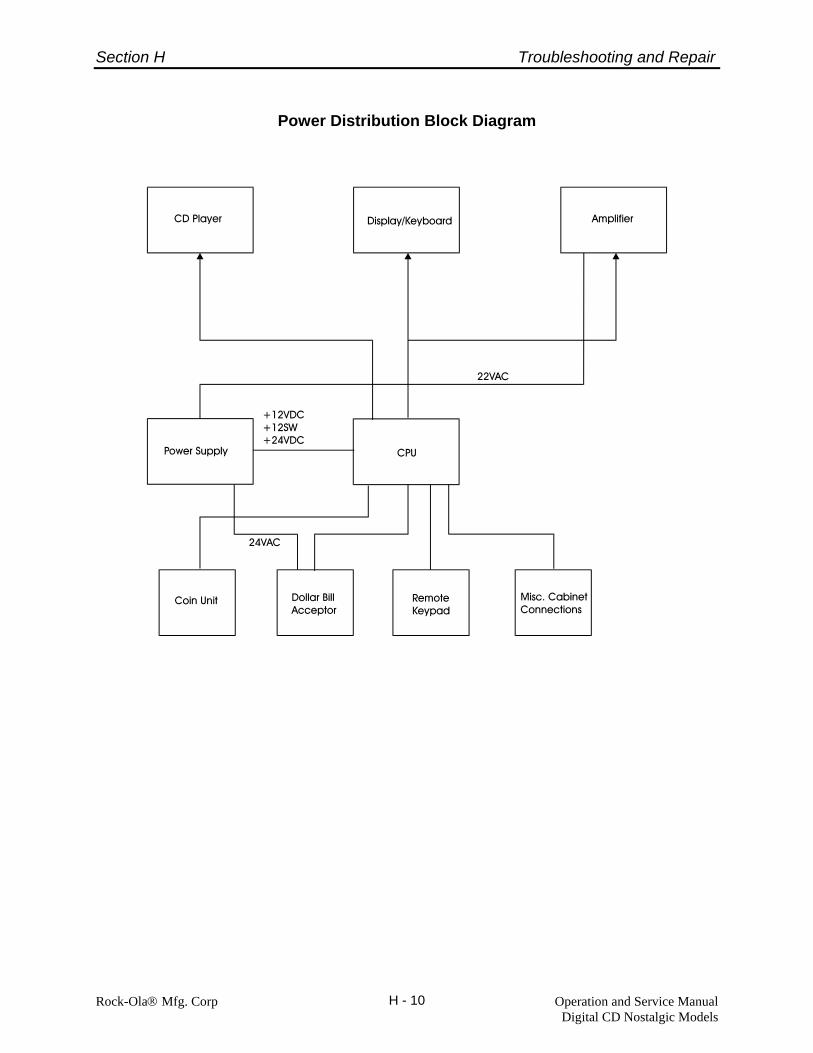
Section H Troubleshooting and Repair
Power Distribution Block Diagram
Rock-Ola® Mfg. Corp Operation and Service Manual Digital CD Nostalgic Models
H - 10

Section H Troubleshooting and Repair
Start Up and Diagnostic Mode Operation Start Up The first thing the SyberSonic Computer does upon start up is to establish communication with the CD Player. If successful, and assuming the machine is in the Play or Service mode, the disc magazine will begin to rotate. During this time, the computer is synchronizing the speed of the magazine motor to the mechanism’s opto sen-sor. It takes 3 revolutions to initialize the disc magazine synchronization. Once initialized, the basket stops at the home position. Also, during the initialization process, the computer is estab-lishing communication with the keyboard and amplifier. If all communication is established and no errors are detected, the machine will enter the play mode. If a problem is detected, the problem will be shown on the keyboard/display. See the Di-agnostic/Power Up Error Code Chart for specific code information. Diagnostic Mode Diagnostics Mode is entered by pressing the Diagnostics Button on the front of the control computer while in the Service Mode. Tests are automatically performed and status messages are displayed as the tests are run. Example Message:
Rock-Ola® Mfg. Corp Operation and Service Manual Digital CD Nostalgic Models
H - 11
Each test is displayed on the bottom line while the test is being run. List of Test Messages: DIAGNOSTICS MODE Testing Ram DIAGNOSTICS MODE Testing E2prom
DIAGNOSTICS MODE Testing Eprom DIAGNOSTICS MODE Testing Rtcc DIAGNOSTICS MODE Testing Keyboard DIAGNOSTICS MODE Testing CD Comm. If all of the tests are successful, the following message will be displayed: DIAGNOSTICS MODE Tests Successful Otherwise, one of the following failure messages will be displayed: DIAGNOSTICS MODE Ram Failure DIAGNOSTICS MODE E2prom Failure DIAGNOSTICS MODE Eprom Failure DIAGNOSTICS MODE Rtcc Failure DIAGNOSTICS MODE Keyboard Failure DIAGNOSTICS MODE CD Comm. Failure Note: If the keyboard/display is non-opera-tional, the error code can be read on the STATUS LED located on the front of the CPU. DIAGNOSTICS MODE
Testing E2prom See the Diagnostic/Power Up Error Codes Chart for Error code details. The Diagnostic Test takes about 50 seconds to run. If the keyboard/display is not illuminated, while in the Service Mode, ensure all four (4) Power Supply LEDs are illuminated, press the DIAG button on the Control Computer once and wait for about 50 seconds for an error code to appear. Then refer to the below chart for further instruction.

Section H Troubleshooting and Repair
Rock-Ola® Mfg. Corp Operation and Service Manual Digital CD Nostalgic Models
H - 12
Diagnostic/Power-Up Error Codes: Readout on LED on the front of the control computer.
Error Value
Device Error
Error Code Explanation
What To Do
0
NONE
All devices passed their specific test.
1
RAM
Unable to write/read each byte in RAM.
Check battery and battery holder, U4 or U5
2
E2PROM
Unable to write/read each byte in E2prom.
Replace U1
3
EPROM
Eprom is corrupt.
Replace U8
4
RTCC
Unable to write/read a valid time in the real time counter clock.
Replace U7
5
KEYBOARD/DISPLAY
Unable to establish communication with the Keyboard/Display.
Check cable, 12 volt power to keyboard (is it lit?) and U2
6
CD PLAYER
Unable to establish communication with the CD Player.
Check connections and cables to CD player. Defective CD Player
7
Reserved
8
EPROM
Eprom is bad, missing, installed in-correctly or is blank.
Check and/or replace U8.
Exit the diagnostic mode by pressing the RESUME button on the computer or closing the door/lid.
Test Mode Rock-Ola’s SyberSonic Electronics System pro-vides an easy to understand and simple to use self-diagnostic and self-testing utility. This sec-tion will provide information designed to assist you in using this tool to quickly diagnose and repair any problem that may develop.
Viewing Error Codes When entering the Service Mode the Syber-Sonic Jukebox automatically checks its memory for the existence of stored error codes. If any exist, the warning “Errors Present in XXXX:” (XXXX indicates the area in which the error ex-ists) will scroll across the digital display to re-mind you to view the error codes. To view the stored error codes: • Enter the set up mode. • Access “View Errors” in the Test Mode
Menu (Quick Find #130).
• Use the Right Pages Button to scroll to the area for which you want to view errors. (i.e. View Page Errors).
• Press Hits. You will see the error code, date
of error and time of error on the display. (See “Test Mode” flow chart in section E for sample displays).
• Refer to the following Charts for information
and what to do about each error.
Using Error Codes After retrieving and reviewing the error code, the next step in the troubleshooting process is to determine why the error code exists. In most cases the problem is a “mechanical” one. That is, the problem could be a mechanical bind, a broken or bent cam, a bad switch or a broken wire. Occasionally, a malfunction may be caused by the electronics. By analyzing the code and its meaning, you can usually deter-mine the cause of the malfunction very easily.

Section H Troubleshooting and Repair
Rock-Ola® Mfg. Corp Operation and Service Manual Digital CD Nostalgic Models
H - 13
If the Error Code Chart refers to a test, the instructions can be found under “Running Tests” later in this section. CPU (Input) Error Codes
Error Value
Input Error
Error Code Explanation
What To Do
C00
SERVICE
Service key depressed for longer than 1 minute.
Check Service Switch on Control Computer, Replace Control Com-puter.
C01
DIAGNOSTIC
Diagnostics key depressed for longer than 1 minute.
Check Diagnostic Switch on Control Computer, Replace Control Com-puter.
C02
RESUME
Resume key depressed for longer than 1 minute.
Check Resume Switch on Control Computer, Replace Control Com-puter
C03
SCAN CANCEL
Scan/Cancel key depressed for 1 minute.
Check Scan/Cancel switch. Check wiring between switch and control computer for a short circuit.
C05
COIN 1
Coin 1 input active for longer than 1 minute.
Check Coin Switch 1, Check wiring between Coin Switch and Control Computer for a short circuit, Replace Control Computer.
C06
COIN 2
Coin 2 input active for longer than 1 minute.
Check Coin Switch 2, Check wiring between Coin Switch and Control Computer for a short circuit, Replace Control Computer.
C07
COIN 3
Coin 3 input active for longer than 1 minute.
Check Coin Switch 3, Check wiring between Coin Switch and Control Computer for a short circuit, Replace Control Computer.
C08
COIN 4
Coin 4 Input active for longer than 1 minute.
Check Coin Switch 4, Check wiring between Coin Switch and Control Computer for a short circuit, Replace Control Computer.
C09
COIN 5
Coin 5 Input active for longer than 1 minute. (In the U.S. this is the Quarter input).
Check Coin Switch 5, Check wiring between Coin Switch and Control Computer for a short circuit, Replace Control Computer.
C10
COIN 6
Coin 6 Input active for longer than 1 minute. (In the U.S. this is the Bill Validator input).
Check Coin Switch 6, Check wiring between Coin Switch and Control Computer for a short circuit, Replace Control Computer.
C11
EXT VOL UP
External Volume Up key de-pressed for longer than 1minute.
Check External Volume Up Switch, Replace Remote Volume Control, Check Remote Volume Control wiring for a short circuit, Replace Control Computer.
C12
EXT VOL DOWN
External Volume Down key de-pressed for longer than 1minute.
Check External Volume Down Switch, Replace Remote Volume Control, Check Remote Volume Control wiring for a short circuit, Replace Control Computer.
Internal Volume Up key de-
Check internal Volume Up Switch, Replace Remote Volume Control,
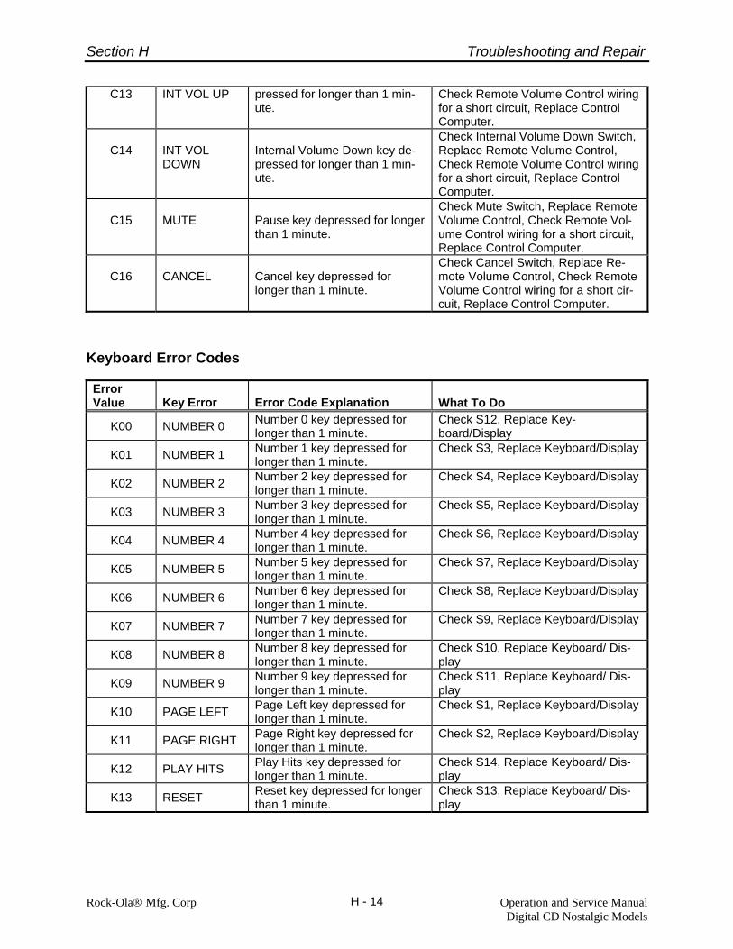
Section H Troubleshooting and Repair
Rock-Ola® Mfg. Corp Operation and Service Manual Digital CD Nostalgic Models
H - 14
C13 INT VOL UP pressed for longer than 1 min-ute.
Check Remote Volume Control wiring for a short circuit, Replace Control Computer.
C14
INT VOL DOWN
Internal Volume Down key de-pressed for longer than 1 min-ute.
Check Internal Volume Down Switch, Replace Remote Volume Control, Check Remote Volume Control wiring for a short circuit, Replace Control Computer.
C15
MUTE
Pause key depressed for longer than 1 minute.
Check Mute Switch, Replace Remote Volume Control, Check Remote Vol-ume Control wiring for a short circuit, Replace Control Computer.
C16
CANCEL
Cancel key depressed for longer than 1 minute.
Check Cancel Switch, Replace Re-mote Volume Control, Check Remote Volume Control wiring for a short cir-cuit, Replace Control Computer.
Keyboard Error Codes Error Value
Key Error
Error Code Explanation
What To Do
K00 NUMBER 0 Number 0 key depressed for longer than 1 minute.
Check S12, Replace Key-board/Display
K01 NUMBER 1 Number 1 key depressed for longer than 1 minute.
Check S3, Replace Keyboard/Display
K02 NUMBER 2 Number 2 key depressed for longer than 1 minute.
Check S4, Replace Keyboard/Display
K03 NUMBER 3 Number 3 key depressed for longer than 1 minute.
Check S5, Replace Keyboard/Display
K04 NUMBER 4 Number 4 key depressed for longer than 1 minute.
Check S6, Replace Keyboard/Display
K05 NUMBER 5 Number 5 key depressed for longer than 1 minute.
Check S7, Replace Keyboard/Display
K06 NUMBER 6 Number 6 key depressed for longer than 1 minute.
Check S8, Replace Keyboard/Display
K07 NUMBER 7 Number 7 key depressed for longer than 1 minute.
Check S9, Replace Keyboard/Display
K08 NUMBER 8 Number 8 key depressed for longer than 1 minute.
Check S10, Replace Keyboard/ Dis-play
K09 NUMBER 9 Number 9 key depressed for longer than 1 minute.
Check S11, Replace Keyboard/ Dis-play
K10 PAGE LEFT Page Left key depressed for longer than 1 minute.
Check S1, Replace Keyboard/Display
K11 PAGE RIGHT Page Right key depressed for longer than 1 minute.
Check S2, Replace Keyboard/Display
K12 PLAY HITS Play Hits key depressed for longer than 1 minute.
Check S14, Replace Keyboard/ Dis-play
K13 RESET Reset key depressed for longer than 1 minute.
Check S13, Replace Keyboard/ Dis-play

Section H Troubleshooting and Repair
Rock-Ola® Mfg. Corp Operation and Service Manual Digital CD Nostalgic Models
H - 15
Mechanism Error Codes Error Value
Mechanism Error
Error Code Explanation
What To Do
M01
MAGAZINE
Unable to locate a compact disc (slot number). Unable to find “Home”.
Run Index Test, Check/Replace Mech Opto Sensor, Check Mech Opto Sensor Wiring, Replace Con-trol Computer. Check magazine motor. Check cam switch wiring.
M02
LOADING
Unable to load a compact disc.
Run Gripper Test, Check 24 VDC, Check Gripper Motor, Check Gripper Motor Wiring, Replace Control Computer. Check cam switches.
M03
UNLOADING
Unable to unload a compact disc.
Run Gripper Test, Check 24 VDC, Check Gripper Motor, Check Gripper Motor Wiring, Replace Control Computer. Check cam switches.
M04
COMMUNICA-TION
Unable to establish communi-cation with CD player.
Check CD player wiring from Control Computer to Laser. Replace CD player. Replace Control Computer.
M05
CD RESPONSE
Unable to obtain the correct response from the CD player.
Check CD player wiring from Control Computer to Laser. Replace CD player. Replace Control Computer.
Page Unit Error Codes Error Value
Page Unit Error
Error Code Explanation
What To Do
P01
PAGE LEFT
Unable to flip the pages left.
Run Pages Test, Check 24 VDC, Check wiring between Page Unit and Control Computer, Check Pages Mo-tor, Check Pages Detent Switch and Wiring, Check Pages Left Switch on Keyboard, Replace Control Com-puter.
P02
PAGE RIGHT
Unable to flip the pages right.
Run Pages Test, Check 24 VDC, Check wiring between Page Unit and Control Computer, Check Pages Mo-tor, Check Pages Detent Switch and Wiring, Check Pages Right Switch on keyboard, Replace Control Computer.

Section H Troubleshooting and Repair
Running Tests PowerUp Test: Keyboard Failure
Rock-Ola’s SyberSonic Electronics System has a set of built-in diagnostic tests that can be run via the keyboard. These tests are designed to eliminate guess work when troubleshooting a specific problem. You have the ability to test all inputs and outputs of the control computer, the electronics and mechanics of the CD Player, the turning of the pages, the digital display and the functions of the mechanism.
PowerUp Test: CD Comm. Failure
Refer to the Diagnostic/Power Up Error Codes Chart for further instruction. CPU Tests Inputs Test The CPU Tests consist of three (3) individual
tests. The Power Up Test, Inputs Test and Out-puts Test.
This test checks the status of the inputs to the control computer. To run this test: Power Up Test - This test checks the internal
functions of the control computer and communi-cation with the CD Player and keyboard.
• Access “Run Inputs Test” (Quick Find 143)
in the Test Mode menu. To run this test access “Run Power Up Test” (Quick Find 142) in the Test Mode Menu. Press HITS. The control computer will run the test. If all tests pass the display will indicate the follow-ing message:
• Press HITS. The control computer will run the test.
• As the test progresses the keyboard display
will indicate which input is tested and its cur-rent logic level (Hi or Lo). Sample displays can be found on the Test Mode Flow chart in Section E of this manual. Refer to the Test Inputs Code Chart for information about each input.
PowerUp Test: No Failures
If a failure occurred one of the following mes-sages will be displayed.
Note: The Normal Logic Level shown on the chart assumes the machine is at rest with the magazine and gripper bow in the home position and the pages at page 1.
PowerUp Test: Ram Failure
PowerUp Test: Eprom Failure
PowerUp Test: E2prom Failure
PowerUp Test: Rtcc Failure
Rock-Ola® Mfg. Corp Operation and Service Manual Digital CD Nostalgic Models
H - 16

Section H Troubleshooting and Repair
Rock-Ola® Mfg. Corp Operation and Service Manual Digital CD Nostalgic Models
H - 17
Test Input Codes: Input Value
Normal Logic Level
Input Location
Input Description
1 Hi S1 on CPU Board RESUME Button. 2 Hi S3 on CPU Board SERVICE Button. 3 Hi S2 on CPU Board DIAGNOSTICS Button. 4 Hi J14.8 on CPU Board PAGE OPTO SENSOR Input Line. 5 Lo J2.3 on CPU Board MAGAZINE OPTO SENSOR Input Line. 6 Hi J5.12 on CPU Board CAM 1 Switch Input Line. 7 Hi J5.11 on CPU Board CAM 2 Switch Input Line. 8 Hi J3.2 on CPU Board IR DETECTOR Input Line. 9 Hi J4.1 on CPU Board COIN 6 Input Line.
10 Hi J4.2 on CPU Board COIN 5 Input Line. 11 Hi J4.3 on CPU Board COIN 4 Input Line. 12 Hi J4.4 on CPU Board COIN 3 Input Line. 13 Hi J4.5 on CPU Board COIN 2 Input Line. 14 Hi J4.6 on CPU Board COIN 1 Input Line. 15 Hi J4.11 on CPU Board DOLLAR BILL JAM Input Line. 16 Hi N/A Unused Input Line. 17 Hi J6.3 on CPU Board POWER SWITCH Input Line. 18 Lo J6.2 on CPU Board SERVICE SWITCH Input Line. 19 Hi J5.7 on CPU Board CANCEL/SCAN BUTTON Input Line. 20 Hi N/A Unused Input Line. 21 Hi N/A Unused Input Line. 22 Hi J7.3 on CPU Board CANCEL/MUTE Matrix Input Line. 23 Hi J7.2 on CPU Board EXT. VOL. UP/EXT. VOL. DOWN Matrix Input
Line. 24 Hi J7.1 on CPU Board INT. VOL. UP/INT. VOL. DOWN Matrix Input
Line. To stop the test, press RESET on the keyboard or RESUME on the control computer.

Section H Troubleshooting and Repair
Rock-Ola® Mfg. Corp Operation and Service Manual Digital CD Nostalgic Models
H - 18
Outputs Test The outputs test checks the voltage level of the control computer outputs. It will either be Gnd (0 Volts) or Vcc (12 or 24 Volts depending on the output). To run the output test, access “Run Outputs Test” (Quick Find 144) in the Test Mode
menu. Press HITS and the test will begin. As the test progresses, the keyboard display will indicate the status of the output line. Sample displays can be found on the Test Mode Flow chart in Section E of this manual.
Test Output Codes: Output Value
Output Level
Output Location
Output Description
1 Gnd J6.7 on CPU Board PLAY COUNTER Output Line. 2 Gnd J6.6 on CPU Board MONEY COUNTER Output Line. 3 Gnd J4.10 on CPU Board DOLLAR BILL ENABLE Output Line. 4 Gnd J4.7 on CPU Board COIN ENABLE Output Line. 5 Gnd J14.2 on CPU Board PAGE LEFT Output Line. 6 Gnd J14.1 on CPU Board PAGE RIGHT Output Line. 7 Gnd J3.3 on CPU Board IR LED FEEDBACK Output Line. 8 Gnd J5.1 on CPU Board GRIP IN MOTOR Output Line. 9 Gnd J5.2 on CPU Board GRIP OUT MOTOR Output Line.
10 Gnd J5.5 on CPU Board MAGAZINE MOTOR Output Line. 11 Gnd J7.4 on CPU Board MUTE/EXT. VOL. DOWN/INT. VOL. DOWN Matrix
Output Line. 12 Gnd J7.5 on CPU Board CANCEL/EXT. VOL. UP/INT. VOL. UP Matrix
Output Line. 13 Gnd J7.6 on CPU Board Unused Matrix Output Line. 14 Gnd J10.1 on CPU Board CLEAR TO SEND 1 Output Line.
Keyboard Test Access “Run Keyboard Test” (Quick Find 132) in the Test Mode Menu. Press HITS. Now as you press a Keyboard Button the Display will indi-cate which button is pressed. Sample displays can be found on the Test Mode Flow chart in Section E of this manual. To exit the Keyboard Test, either press RE-SUME on the Control Computer or close the door/lid. (Pressing RESET will not cause you to exit from this test as the reset switch is one that is checked during the Keyboard Test). The keyboard/display has its own built-in diag-nostics system to test all aspects of the device to ensure proper functions and reliability. To run the keyboard/display diagnostics test, you must first push and hold the test switch then connect a 12 volt DC source to plug J2 pin 4 (pos) and pin 5 (neg). Release the test switch and then the device is in self-diagnostics. It will
fill the display with varying characters for ap-proximately 2 seconds. The display will then blank and when the keys on the keyboard are pushed, they will be shown on the display. To take the device out of test, you must press the RESET and HITS keys at the same time or disconnect the power to the keyboard. Display Test Access “Run Display Test” (Quick Find 133) in the Test Mode Menu. Press HITS. The display will scroll through all of its available characters. Observe that all the characters are properly dis-played. Sample displays can be found on the Test Mode Flow chart in Section E of this man-ual. To exit the display test, either press RESET on the Keyboard, press RESUME on the Control Computer or close the door/lid.

Section H Troubleshooting and Repair
Rock-Ola® Mfg. Corp Operation and Service Manual Digital CD Nostalgic Models
H - 19
Pages Test Access “Run Pages Test” (Quick Find 134) in the Test Mode Menu. Press Hits. The Title Pages will run a full cycle from front to back. Observe that the pages move smoothly back and forth and that they stop in the correct posi-tion. Sample displays can be found on the Test Mode Flow chart in Section E of this manual. To run the test again, press HITS. To exit the test, either press RESET on the Key-board, press RESUME on the Control Computer or close the door/lid. Mechanism Tests Rock-Ola’s SyberSonic System provides five (5) individual mech tests which together create a comprehensive testing tool for the CD Mecha-nism and CD Player. Included are: • Index Test which checks the synchroniza-
tion between the Control Computer and the CD Magazine.
• Gripper Test which allows the testing of the
electrical functions of the Gripper Motor as well as the mechanical functions of the Grip-per Bow.
• Short Test which causes the mechanism to
pick up each CD, read its table of contents and display the number of tracks on the CD.
• Test All Disc which causes the mechanism
to pick up each CD, display the number of tracks on that CD then play five (5) seconds from each track on that CD.
• Run CD Tests which provides a testing tool
for the CD Player. This includes a Play Test and a Servo Test. The Play Test allows the testing of the Play Functions of the CD Player. The Servo Test allows the Testing of the electro-mechanical functions of the CD Player.
Running Mechanism Tests Index Test Access “Run Index Test” (Quick Find 145) in the View Mech Tests area of the Test Mode Menu. Press HITS. Select “Once” or “Continuous”. The
disc magazine will rotate a full revolution then stop at position 00, pick up the disc then put it back away. It will then go to position 01 and repeat the above procedure. After 01 it will go to positions 49, 50, 98 and 99 to check synchroni-zation at those positions. While the test is running you should check to see that the disc is being picked up and put away properly. See Magazine Indexing Adjust-ment in Section G for details. Sample displays can be found on the Test Mode Flow Chart found in Section E of this manual. To exit this test, either press RESET on the Keyboard, press RESUME on the Control Com-puter or close the door/lid. Gripper Test Access “Run Gripper Test” (Quick Find 146) in the View Mech Tests area of the Test Mode Menu. Press HITS. The display will indicate “Push Cancel/Scan to Move Gripper.” Doing so will cause the Gripper Motor to run allowing you to check the electrical and mechanical functions of the Gripper Bow and related mechanics. Also check the Gripper Rest Adjustment. See Grip-per Rest Adjustment in Section G for details. For sample displays, see the Test Mode Flow Chart in Section E of this Manual. To stop the test, either press RESET on the Keyboard, press RESUME on the Control Com-puter or close the door/lid. Short Test Access “Run Short Test” (Quick Find 147) in the View Mech Tests area of the Test Mode Menu. Press HITS. The Disc Magazine will rotate a full revolution and stop at position 00. The disc in slot 00 will be picked up and placed on the CD Player. It will then be spun to read its table of contents. Once the table of contents has been read, the number of tracks on that CD will be displayed and then the disc will be put back into the magazine. The magazine will then stop at position 01, 02, 03... etc. and perform the above procedure. The Short Test will continue until all of the magazine positions have been checked.

Section H Troubleshooting and Repair
Rock-Ola® Mfg. Corp Operation and Service Manual Digital CD Nostalgic Models
H - 20
For sample displays, see the Test Mode Flow Chart in Section E of this Manual. To stop the test, either press RESET on the Keyboard, press RESUME on the Control Com-puter or close the door/lid. Test All Disc (AKA Long Test) Access “Test All Disc” (Quick Find 148) in the View Mech Tests area of the Test Mode Menu. Press HITS. The Disc Magazine will rotate a full revolution and stop at position 00. The disc in slot 00 will be picked up and placed on the CD Player. It will then be spun to read its table of contents. Once the table of contents has been read, the number of tracks on that CD will be displayed and then five (5) seconds of each song on that disc will be played. After all tracks from that disc have been played it will be put back into the magazine. For sample displays, see the Test Mode Flow Chart in Section E of this Manual. The magazine will then stop at position 01, 02, 03... etc. and perform the above procedure. Test All Disc will continue until all of the magazine positions have been checked. To stop the test, either press RESET on the Keyboard, press RESUME on the Control Com-puter or close the door/lid. Run CD Tests Access “Run CD Tests” (Quick Find 149) in the View Mech Tests area of the Test Mode Menu. Press HITS. The magazine will rotate a full revolution then stop and pick up the disc in posi-tion 00. At this point you may choose “Run Play Test” by pressing HITS or you may choose “Run Servo Test” by pressing the RIGHT TURN PAGES button then pressing HITS.
Play Test Four (4) play functions are available by using Keyboard Buttons 1 - 4.
• #1 Start play • #2 Stop play • #3 Next Track • #4 Previous Track
To stop the test, either press RESET on the Keyboard, press RESUME on the Control Com-puter or close the door/lid. Servo Test Five (5) servo functions are available by using Keyboard Buttons 1 - 5.
• #1 Focus On • #2 Focus Off • #3 Turntable On • #4 Turntable Off • #5 Arm In/Out
To stop the test, either press RESET on the Keyboard, press RESUME on the Control Com-puter or close the door/lid.

Section H Troubleshooting and Repair
Rock-Ola® Mfg. Corp Operation and Service Manual Digital CD Nostalgic Models
H - 21
Amplifier Troubleshooting Rock-Ola’s Digital SyberSonic amplifier has different color LED’s to indicate the status of various sys-tems. The state of the LED’s is the most important tool when beginning to troubleshoot the audio system.
LED’s
* Power Green Preamp PCB Power On - Normal Off - No power to the pre-amp board
* Status Orange State of the MP & Paging System
On - Normal Blinking - Paging System Active Off - Processor Faulted
* Com Orange State of the MP & Communication
On - Normal Flashing - Communicating with the Jukebox CPU Off - Settings not loaded
* Overload Red Power Amp Muting On - Amplifier muted* Blinking - Power Amp Overload Off - Normal
* The Power amplifier is muted whenever a CD is not in play and the background music system is off.
Symptom LED Problem Solution
No Sound Green LED Off No Power to Pre-amp Check that preamp and power amp PCB’s are properly mated.
Green LED On Status LED On Comm LED Off
Not set up Check communications cable from amplifier to CPU.
Green LED On Status LED Off Processor not running Replace Pre-amp PCB
Green LED On Orange LED’s On Red LED On
Amplifier Muted Be sure CD is in play (Now Play-ing on the Display) Defect in Power Amplifier
Green LED On Orange LED’s On Red LED Blinking
Amplifier Overload
Unplug speakers. If red LED stays off, check for speaker overload. If red LED still blinks, replace power amplifier PCB.
Amplifier Test Mode The Digital SyberSonic Amplifier contains a test mode. This mode initializes the DSP’s to a straight through, 0 gain signal path. This would be the same as EQ’s flat, Balance center, CD Input, Volumes 40. To use, power up the amplifier without the com-munication cable connected. Press the test but-ton located under the LED’s. CAUTION: If a live input is connected to the CD inputs, full volume output will appear at the speaker connections. Plug the audio output from a walkman or signal generator into the CD Input jacks. Audio should
be present on all output jacks. If it does, the am-plifier is working properly. Bad or Distorted Sound • Check Red LED’s while a CD is in play. • Red LED on or flashing - Indicates the
channel is overloaded. Check the speakers and speaker wiring.
• Red LED’s all off - Note which channel
sound bad. Reverse the input connections. If the opposite channel now sounds bad,
Section H Troubleshooting and Repair
Rock-Ola® Mfg. Corp Operation and Service Manual Digital CD Nostalgic Models
H - 22
the input source (CD Input or AUX BGM In-put) is defective. If the same channel still sounds bad, replace the affected channel’s power amplifier board.
• Overload System Operation (Section D)
Weak Bass From The External Speakers • Check speaker connections. All external
speakers must be wired in phase. Positive (+) to positive (+) and negative (-) to nega-tive (-).

Section
I
Major ComponentSchematics
- CPU- Amplifier/Power Supply- Audio Output Panel- Keboard/Display- Volume Control- Crossover- Transformer- Lighting Wiring Diagram (CD-8V)- Primary Power Block Diagram
I - 1

Section I Major Component Schematics
Rock-Ola® Mfg. Corp. Operation and Service ManualDigital CD Nostalgic Models
I - 2
Computer (CPU)
PCB
Ass
y, C
PU,
5839
9-1A
+5
IN47
33A

Section I Major Component Schematics
Rock-Ola® Mfg. Corp. Operation and Service ManualDigital CD Nostalgic Models
I - 3
PCB
Ass
y, C
PU,
5839
9-1A

Section I Major Component Schematics
Rock-Ola® Mfg. Corp. Operation and Service ManualDigital CD Nostalgic Models
I - 4
PCB
Ass
y, C
PU,
5839
9-1A
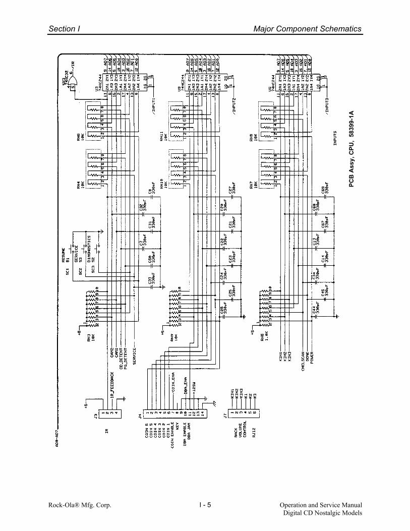
Section I Major Component Schematics
Rock-Ola® Mfg. Corp. Operation and Service ManualDigital CD Nostalgic Models
I - 5
PCB
Ass
y, C
PU,
5839
9-1A

Section I Major Component Schematics
Rock-Ola® Mfg. Corp. Operation and Service ManualDigital CD Nostalgic Models
I - 6
PCB
Ass
y, C
PU,
5839
9-1A
+24
IN53
47A

Section I Major Component Schematics
Rock-Ola® Mfg. Corp. Operation and Service ManualDigital CD Nostalgic Models
I - 7
Bill of Materials - PCB Assy, CPU, 58399-1A
Reference Part Reference PartBack of board across 5V Diode, IN4733A R10 Resistor: 180 ohm, 1/4W, 5%Supply R5, R6 Resistor: 2.2K ohm, 1/4W, 5%Back of board across R12 Diode, IN5347A R2, R20 Resistor: 4.7K ohm, 1/4W, 5%BAT1 Battery, 3V Lithium R3 Resistor: 75K ohm, 1/4W, 5%C1, C2, C3, C6, C9, C10, C11, Capacitor: .1uF, 50V, Mono R12 Resistor: 75 ohm, 3W, 5%C15, C16, C17, C28, C29, RN4, RN6, RN7, RN8, RN10, Resistor SIP Network, 10KC30, C35-C38, C41, C47-C55, RN11 ohm, 8 pin isolatedC59, C65, C66, C70, RN1, RN2, RN12 Resistor SIP Network, 470C71, C72, C79-C83 ohm, 8 pin isolatedC12, C18, C19, C42, C43 Capacitor: 2200pF, 50V Mono RN14 Resistor SIP Network, 4.7KC84, C85 Capacitor: 22pF, 100V, Mono ohm, 8 pin isolatedC7, C8, C13, C14, C20-C27, Capacitor: 330pF, 100V, Mono RN5 Resistor SIP Network, 1.0KC31-C34, C44,C45, C56, ohm, 10 pin commonC57, C58, C60, C61, C62, RN3, RN9, RN13, RN15 Resistor SIP Network 10k ohmC63, C64, C67, C68, C69, C73 10 pin commonC78 S1, S2, S3 Switch, SPST MomentaryC4 Capacitor: 100uF, 25V SP1 Spacer, 3/8” for CR3C5, C46 Capacitor: 10uF, 35V SU1 28 pin Socket, low profileC39, C40 Capacitor: 470uF, 35V SU8 32 pin Socket, low profileCR1 Diode, IN4002 SU3 Battery Holder 25mm dia.CR2, CR6 Diode Bridge 1A TP1 Test PointCR3 Light Emitting Diode, IR U15, U24 I.C. L293 - Quad Half-H DriverCR4, CR5 Diode, IN4148 U4 I.C. MAX691A, MicroprocessorDP1 7 Segment Disp - com anode SupervisorHS1 Heatsink TO-220 U11 I.C. ULN2003A, H-V, H-CHW1 Screw, #6-32 x 3/8 Pan Hd U7 I.C. 62421B - CMOS real timeHW2 Keps Nut #6-32 clockJ3 Connector: 4 pin .1 U17 I.C. 80C32 - 8 bitJ9, J10 Connector: 6 pin .1 MicrocomputerJ8 Connector: 8 pin .1 U5 62256-CMOS-32,768 Word byJ14 Connector: 9 pin .1 8 Bit LSIJ6 Connector: 10 pin .1 U1 I.C. 28C64 - EEPROM 8KX8J4 Connector: 14 pin .1 U8 I.C. 27C020J2 Connector: 4 pin .156 U19, U20 I.C. 75176 - Differential BusJ1 Connector: 8 pin .156 TransceiverJ5 Connector: 12 pin .156 U14 I.C. 74HCT373 H-CMOS OctalJ13 Connector: 4 pin RJH side. U18 I.C. 74HC00 H-CMOS Quad 2
entry L.P input nandJ7, J11, J12 Connector: 6 pin RJ12 side U23 74HC32 H-CMOS Quad 2
entry L.P. input or gateJP5 Jumper Blk, 2 pin U10, U13 I.C. 74HC138 H-CMOS 3/8JP1, JP2, JP3 Jumper Blk, 3 pin DecoderJP4 Jumper Blk, 4 pin U3, U6, U9 I.C. 74HC244 H-CMOS OctalQ1 I.C. LM7805C BufferQ2 I.C. LM7809C U2, U12, U16 I.C. 74HC273 H-CMOS OctalQ3 NPN Transistor PN2222 DFF w/ clearR7, R8, R9 Resistor: 100 ohm, 1/4W, 5% U21, U22 4051 CMOS 8 Channel AnalogR4, R21, R50 Resistor: 10K ohm, 1/4W, 5% Y1 Crystal, 11.0592 MhzR1, R11 Resistor: 220 ohm, 1/4W, 5%

Section I Major Component Schematics
Rock-Ola® Mfg. Corp Operation and Service ManualDigital CD Nostalgic Models
I - 8
Digital Preamp
PCB
Ass
y, D
igita
l Pre
amp
(DSP
#1
& In
puts
), 60
441-
1A

Section I Major Component Schematics
Rock-Ola® Mfg. Corp Operation and Service ManualDigital CD Nostalgic Models
I - 9
PCB
Ass
y, D
igita
l Pre
amp
(CPU
&M
icro
phon
e C
ircui
ts),
6044
1-1A

Section I Major Component Schematics
Rock-Ola® Mfg. Corp Operation and Service ManualDigital CD Nostalgic Models
I - 10
PCB
Ass
y, D
igita
l Pre
amp
(DSP
#2)
, 604
41-1
A
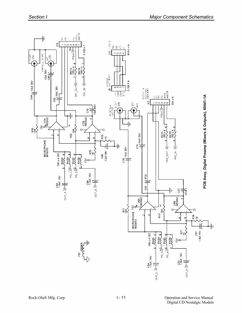
Section I Major Component Schematics
Rock-Ola® Mfg. Corp Operation and Service ManualDigital CD Nostalgic Models
I - 11
PCB
Ass
y, D
igita
l Pre
amp
(Mix
ers
& O
utpu
ts),
6044
1-1A

Section I Major Component Schematics
Rock-Ola® Mfg. Corp Operation and Service ManualDigital CD Nostalgic Models
I - 12
PCB
Ass
y, D
igita
l Pre
amp
(Pow
er S
uppl
ies)
, 604
41-1
A
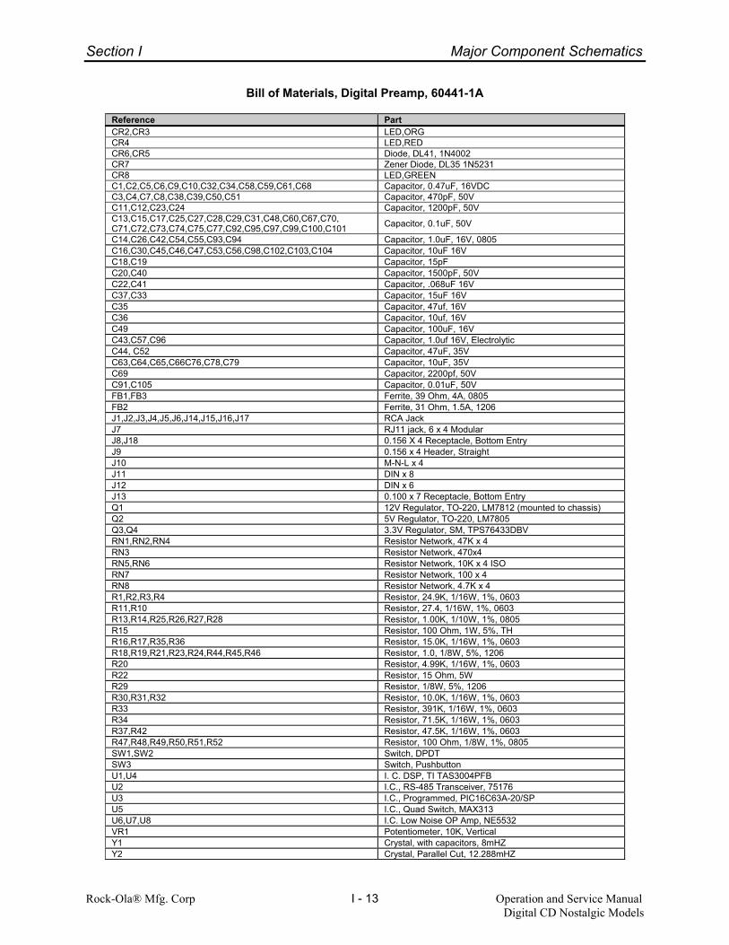
Section I Major Component Schematics
Rock-Ola® Mfg. Corp Operation and Service ManualDigital CD Nostalgic Models
I - 13
Bill of Materials, Digital Preamp, 60441-1A
Reference PartCR2,CR3 LED,ORGCR4 LED,REDCR6,CR5 Diode, DL41, 1N4002CR7 Zener Diode, DL35 1N5231CR8 LED,GREENC1,C2,C5,C6,C9,C10,C32,C34,C58,C59,C61,C68 Capacitor, 0.47uF, 16VDCC3,C4,C7,C8,C38,C39,C50,C51 Capacitor, 470pF, 50VC11,C12,C23,C24 Capacitor, 1200pF, 50VC13,C15,C17,C25,C27,C28,C29,C31,C48,C60,C67,C70,C71,C72,C73,C74,C75,C77,C92,C95,C97,C99,C100,C101 Capacitor, 0.1uF, 50V
C14,C26,C42,C54,C55,C93,C94 Capacitor, 1.0uF, 16V, 0805C16,C30,C45,C46,C47,C53,C56,C98,C102,C103,C104 Capacitor, 10uF 16VC18,C19 Capacitor, 15pFC20,C40 Capacitor, 1500pF, 50VC22,C41 Capacitor, .068uF 16VC37,C33 Capacitor, 15uF 16VC35 Capacitor, 47uf, 16VC36 Capacitor, 10uf, 16VC49 Capacitor, 100uF, 16VC43,C57,C96 Capacitor, 1.0uf 16V, ElectrolyticC44, C52 Capacitor, 47uF, 35VC63,C64,C65,C66C76,C78,C79 Capacitor, 10uF, 35VC69 Capacitor, 2200pf, 50VC91,C105 Capacitor, 0.01uF, 50VFB1,FB3 Ferrite, 39 Ohm, 4A, 0805FB2 Ferrite, 31 Ohm, 1.5A, 1206J1,J2,J3,J4,J5,J6,J14,J15,J16,J17 RCA JackJ7 RJ11 jack, 6 x 4 ModularJ8,J18 0.156 X 4 Receptacle, Bottom EntryJ9 0.156 x 4 Header, StraightJ10 M-N-L x 4J11 DIN x 8J12 DIN x 6J13 0.100 x 7 Receptacle, Bottom EntryQ1 12V Regulator, TO-220, LM7812 (mounted to chassis)Q2 5V Regulator, TO-220, LM7805Q3,Q4 3.3V Regulator, SM, TPS76433DBVRN1,RN2,RN4 Resistor Network, 47K x 4RN3 Resistor Network, 470x4RN5,RN6 Resistor Network, 10K x 4 ISORN7 Resistor Network, 100 x 4RN8 Resistor Network, 4.7K x 4R1,R2,R3,R4 Resistor, 24.9K, 1/16W, 1%, 0603R11,R10 Resistor, 27.4, 1/16W, 1%, 0603R13,R14,R25,R26,R27,R28 Resistor, 1.00K, 1/10W, 1%, 0805R15 Resistor, 100 Ohm, 1W, 5%, THR16,R17,R35,R36 Resistor, 15.0K, 1/16W, 1%, 0603R18,R19,R21,R23,R24,R44,R45,R46 Resistor, 1.0, 1/8W, 5%, 1206R20 Resistor, 4.99K, 1/16W, 1%, 0603R22 Resistor, 15 Ohm, 5WR29 Resistor, 1/8W, 5%, 1206R30,R31,R32 Resistor, 10.0K, 1/16W, 1%, 0603R33 Resistor, 391K, 1/16W, 1%, 0603R34 Resistor, 71.5K, 1/16W, 1%, 0603R37,R42 Resistor, 47.5K, 1/16W, 1%, 0603R47,R48,R49,R50,R51,R52 Resistor, 100 Ohm, 1/8W, 1%, 0805SW1,SW2 Switch, DPDTSW3 Switch, PushbuttonU1,U4 I. C. DSP, TI TAS3004PFBU2 I.C., RS-485 Transceiver, 75176U3 I.C., Programmed, PIC16C63A-20/SPU5 I.C., Quad Switch, MAX313U6,U7,U8 I.C. Low Noise OP Amp, NE5532VR1 Potentiometer, 10K, VerticalY1 Crystal, with capacitors, 8mHZY2 Crystal, Parallel Cut, 12.288mHZ

Section I Major Component Schematics
Rock-Ola® Mfg. Corp Operation and Service ManualDigital CD Nostalgic Models
I - 14
Digital Power Amp Module
PCB
Ass
y, D
igita
l Pow
er A
mp
Mod
ule,
604
42-A

Section I Major Component Schematics
Rock-Ola® Mfg. Corp Operation and Service ManualDigital CD Nostalgic Models
I - 15
PCB
Ass
y, D
igita
l Pow
er A
mp
Mod
ule,
604
42-A

Section I Major Component Schematics
Rock-Ola® Mfg. Corp Operation and Service ManualDigital CD Nostalgic Models
I - 16
Bill of Materials, Digital Power Amp Module, 60442-A
Reference PartBR1 Bridge Rectifier, 100PIV, 8 AMP *C1 Cap, .1uf 100V Thru-holeC3,C8,C9,C27,C28,C42,C46,C47,C48 Cap, 0.1uF, 50V 0805C4,C22,C25 Cap, 0.1uf, 50V Thru-holeC5 Cap, 100 uF 35V AlumC6,C10,C24,C35 Cap, 100pF, 50V 0805C11,C12 Cap, 47uF 16V AlumC13 Cap, 560pF, 50V 0805C14 Cap, 330pF, 50V 0805C15,C17 Cap, 3.3uF, 25V AlumC16,C18,C19,C20 Cap, 0.22uF, 50V Thru-holeC21, C26 Cap, 100 uF, 50V AlumC31,C32,C33,C34 Cap, 1000pF, 50V 0805C39,C38 Cap, 0.1uF 100V 1210C43,C45 Cap, 1.0uF 50V AlumC44 Cap, 22uF 25V AlumC51,C52 Cap, 10,000 uF, 35V AlumD1,D2,D3 Diode, 11DQ09 *D4 LED, Red Diffused, Hi-Eff, T-1 3/4D5 Diode, 1N4736A Thru-holeD6 Diode, 1N5243A Thru-holeD7 Diode, 1N5235B Thru-holeD8,D9,D11,D12 Diode, MUR120 Thru-holeD10 Diode, 1N4148 Thru-holeJP2,JP3 Header, 0.156 x 4 STR 0.625 in long (Note 5)*J1 Header, 0.156 x 3 STRJ2 Header, 0.100 x 7 STR (Note 6) *J7, J8 Screw Terminal *K1 Relay, DPDT *L1 Inductor, Shielded, 100 uH *L2,L3 Inductor, Torroid, 11.3 uH (Note 7) *L6 Ferrite Bead, 0603 *Q1 Regulator, LM7805CT, 5VDC, 1A, TO-220Q2,Q3,Q4 Transistor, MOSFET 2N7000, TO-92Q5 Transistor, PNP, 2N3906, TO-92R1,R3,R26,R27 Res, 20K, 1/8W, 1%, Thru-holeR2,R9 Res, 10K, 1/8W, 5%, Thru-holeR4 Res, 2K, 1/8W, 5%, Thru-holeR5,R11,R12,R15,R18,R35,R36 Res, 1.0K, 1/8W, 1%, Thru-holeR7,R8,R21,R25 Res, 9.1K, 1/8W, 1%, Thru-holeR13,R10 Res, 6.2, 2W, 5%, MF, Thru-holeR30,R14 Res, 243K, 1/8W, 1%, Thru-holeR17 0 Ohm Jumper, 1206R19 Res, 8.2K, 1/8W, 1%, Thru-holeR20,R22,R23,R24 Res, 1.1K, 1/8W, 1%, Thru-holeR34,R33 Res, 249 Ohm, 1/8W, 1%, Thru-holeR37,R49,R52,R54,R56 Res, 51K, 1/10W, 5%, 0805R38,R50 Res, 10K, 1/10W, 5%, 0805R39,R51,R53 Res, 100K, 1/10W, 5%, 0805R40 Res, 3K, 1/10W, 5%, 0805R42 Res, 200K, 1/10W, 5%, 0805R43 Res, 80.6K, 1/10W, 1% or better, 0805R44 Res, 249K, 1/10W, 5%, 0805R45 Res, 24.9K, 1/10W, 1% or better, 0805R47 Res, 14.7K, 1/10W, 1% or better, 0805R48 Res, 34.8K, 1/10W, 1%, 0805R55 Res, 300 Ohm, 1/10W, 5%, 0805U1 IC, Class T Power Amp Module *U2 IC, OP Amp LM358 DIP-8U3 IC, Comparator, LM339, DIP-14HS1 Heat Sink, Custom to RMC Specifications *
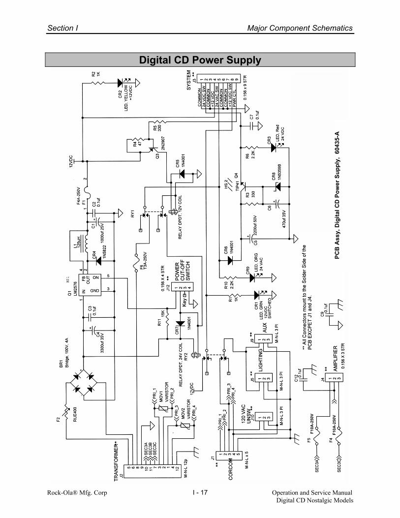
Section I Major Component Schematics
Rock-Ola® Mfg. Corp Operation and Service ManualDigital CD Nostalgic Models
I - 17
Digital CD Power Supply
PCB
Ass
y, D
igita
l CD
Pow
er S
uppl
y, 6
0435
-A
F10A
-250
V
F10A
-250
V

Section I Major Component Schematics
Rock-Ola® Mfg. Corp Operation and Service ManualDigital CD Nostalgic Models
I - 18
Bill of Materials, Digital CD Power Supply, 60435-A
Reference PartBR1 Bridge, 100V, 4ACR1 LED, GRNCR2 LED, YELLOWCR3 LED, RedCR4 Diode, Schotkey, 1N5822CR5,CR6,CR7 Diode, 1N4001CR8 Diode, 1N5359BCR9 LED, ORGC1 Capacitor, 1000uf 25VC2,C3,C7,C9,C12 Capacitor, 0.1ufC4 Capacitor, 3300uf 35VC5 Capacitor, 2200uf 50VC6 Capacitor, 470uf 35VF1 Fuse, Fast Acting, 4A-250VF2 Polyfuse, 4A, RUE400F4,F5 Fuse, Fast Acting, 10A-250VF6 Fuse, Time Delay, 3A-250VJ1 PC Header, M-N-L x 5J2 PC Header, M-N-L 12pJ3 0.156 x 9 Header, StraightJ4 0.156 X 3 Header, StraightJ5,J9,J10 PC Header, M-N-L 3 PlJ12 0.156 X 4 Header, StraightL1 Inductor, 125uHMOV1,MOV2 Metal Oxide Varistor, 140VAC, 1250SAQ1 Regulator, 12V switching, LM2576Q3 Transistor, 2N2907Q4 Transistor, TIP41RY1 Relay DPDT, 12V CoilRY2 Relay DPDT, 24V CoilR1,R2 Resistor, 1KR5,R3 Resistor, 330R4 Resistor, 47R10,R6 Resistor, 2.2KR11 Resistor, 15K

Section I Major Component Schematics
Rock-Ola® Mfg. Corp Operation and Service ManualDigital CD Nostalgic Models
I - 19
Digital Auxiliary Amp
PCB Assy, Digital Auxiliary Amp, 60429-1A
TO AUDIO DISTRIBUTION
TO SPEAKERS
OVERLOAD
RO
LOAG
PGMUTEHMUTE
TO AMPLIFIER
R-R+L-
L+L+
L+L-R-R+
R+
GNDGND
POWER
STEREO / MONO
* Mounts to Solder Side of PCB
J2
0.100 x 7
1234567
J3
0.156 x 4
1234
J5
TERM BLOCK
1234
J4
M-N-L x 4
1234
CR1
LED, RED
R1
2.2K, 1/4W
J6
0.156 X 4
1234
CR2LED, GREENR2
4.7K, 1/4W
J1
DIN x 6
123456
SW1
SW DPDT
T1Transformer, 600 Ohm, 1:1 *
T2
Bill of Materials
Reference PartCR1 LED, REDCR2 LED, GREENJ1 Connector, DIN x 6J2 0.100 x 7, Receptacle, Bottom EntryJ3,J6 0.156 X 4, Receptacle, Bottom EntryJ4 M-N-L x 4, PCB Mount HeaderJ5 Terminal Block, 4 placeR1 Resistor, 2.2K, 1/4WR2 Resistor, 4.7K, 1/4W

Section I Major Component Schematics
Rock-Ola® Mfg. Corp. Operation and Service ManualDigital CD Nostalgic Models
I - 20
Audio Output Panel 70107-A
4 ohm2 ohm
1 ohm
0.5 ohm
INPUT
JUKEBOXSPEAKERS
0.5 ohm
1 ohm
4 ohm2 ohm
COM
COM
LEFT
RIGHT LEFT
RIGHT
J2
M-N-L x 4
1234
T2
AUDIO TRANSFORMER
911
7
4
6
3
1
J1
CON, 9 PIN M-N-L
123456789
J3
Terminal Block
12345
J5Pad for 20 AWG stranded wire.
1
J6
1
T1
AUDIO TRANSFORMER
911
7
4
6
3
1
J4
Terminal Block
12345

Section I Major Component Schematics
Rock-Ola® Mfg. Corp. Operation and Service ManualDigital CD Nostalgic Models
I - 21
Keyboard/Display

Section I Major Component Schematics
Rock-Ola® Mfg. Corp. Operation and Service ManualDigital CD Nostalgic Models
I - 22
Bill of Materials, PCB Assy, Keyboard/Display, 58926-A
Reference PartC1 Capacitor 0.22uFC2 Capacitor 100uFC3, C4 Capacitor 0.1uFC5, C6 Capacitor 330pFCR1 DiodeJ1 Connector (Display)J2 Connector (CPU)J3 Connector (Backlight)Q1 I.C. LM78L05RN1 Resistor 47KRN2, RN3 Resistor 1KRN4 Resistor 47K, (COM)R1 Resistor 390 ohmR2 Resistor 470 ohmR3 Resistor 30 ohm, 5WS1 Mini pushbutton (Test)S2 Mini pushbutton (PG L)S3 Mini pushbutton (PG R)S4 - S13 Mini pushbutton

Section I Major Component Schematics
Rock-Ola® Mfg. Corp. Operation and Service ManualDigital CD Nostalgic Models
I - 23
Removable Volume Control(Back of Machine)
PCB Assy, Volume Control, 58515-A
Bill of Materials - Volume Control PC Board Assembly, 58515-A
Reference PartJ1 Conn Jack RJ12 PCB Low Prof w/ StopsS1 - S6 Switch SPST, Mom, PB NO

Section I Major Component Schematics
Rock-Ola® Mfg. Corp. Operation and Service ManualDigital CD Nostalgic Models
I - 24
Crossover
PCB Assy, Crossover, 60717-A
All resistors 5 watt 10%All capacitors 100 VDC
INPUT
INPUT
SUBWOOFER
SUBWOOFER
HORN TWEETER
HORN TWEETER
6 1/2" MIDRANGE
6 1/2" MIDRANGE
COMMONCOMMONCOMMONCOMMON
R4 62 ohm
C63.3uf
C2 47uf
C33.3uF
C7 47uf
J1
I/O
123456789
101112
R1 62 ohm
C1 3.9uf
C8 3.9uf
R2 10 ohm
R310 ohm
R6
39 ohm
R5
39 ohm
L3 8 mh
L2 8 mh
L4 1.5 mh
L1 1.5 mh
Bill of Materials, PCB Assy, Crossover, 60717-A
Reference PartC1, C8 Capacitor 3.9 ufC2, C7 Capacitor 47 ufC6, C3 Capacitor 3.3 uf
J1 Header 12 pinL1, L4 Coil 1.5 mhL2, L3 Coil 8 mhR1, R4 Resistor 62 ohmR2, R3 Resistor 10 ohmR5, R6 Resistor 39 ohm

Section I Major Component Schematics
Rock-Ola® Mfg. Corp. Operation and Service ManualDigital CD Nostalgic Models
I - 25
Transformer 60681-A
T/F
T/F
PRIMARY # 1115 VAC
SEC # 1PRIMARY # 2115 VAC
SEC # 2
SEC # 3
Attached to Frame
.
BLACK / GREEN
WHT/BLU
WHITE
BLACK
17VAC @ 4A
22 VAC 3A
44VCT @ 7A
GREEN / YELLOW
PIN 1
#10 LUG
.
GR
EE
N (2
)
BLU
E (2
)
OR
ANG
E
OR
ANG
E
OR
ANG
E / W
HIT
E

Section I Major Component Schematics
Rock-Ola® Mfg. Corp. Operation and Service ManualDigital CD Nostalgic Models
I - 26
Lighting Wiring Diagram, CD-8
BALLASTRED
REDYELLOW
MM
LIGHT ARCH
BUBBLE TUBEHEATER
BA
LLA
ST
RED (2)
YELLOW
M
BUBBLE TUBEHEATER
BUBBLE TUBEHEATER
BA
LLAS
T
RED (2)
YELLOW
M
BUBBLE TUBEHEATER
RIGHT SIDELIGHT BAR
LEFT SIDELIGHTBAR
RED (2)YEL
BALLASTWHITEBLK
JUNCTION BOX
LAMP
FL. LAMP
FL. LAMP
1.6K 10W
FL. L
AMP
1.6K 10W
1.6K 10W
FL. LAM
P
1.6K 10W
STAR LAMP
LOWER LAMP
TITLE LAMP
LOGO LAMP
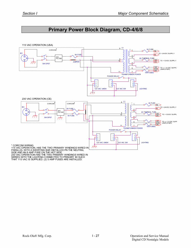
Section I Major Component Schematics
Rock-Ola® Mfg. Corp. Operation and Service ManualDigital CD Nostalgic Models
I - 27
Primary Power Block Diagram, CD-4/6/8
RFIFILTER
CORCOM
CORCOMCORCOM
RFIFILTER
TO +24VDC SUPPLY
TO +/- 31VDC SUPP(AMPLIFIER)
TO +12VDC SUPPL
TO +24VDC SUPPLY
TO +/- 31VDC SUPPLY(AMPLIFIER)
TO +12VDC SUPPLY
230 VAC OPERATION (CE)
115 VAC OPERATION (USA)
*
**
* CORCOM WIRING:115 VAC OPERATION, HAS THE TWO PRIMARY WINDINGS WIRED INPARALLEL WITH A SHORTING BAR INSTALLED PN THE NEUTRALSIDE AND AN 8 AMP FUSE ON THE HOT SIDE.230 VAC OPERATION HAS THE TWO PRIMARY WINDINGS WIRED INSERIES WITH THE LIGHTING CONNECTED TO PRIMARY #2 SUCHTHAT 115 VAC IS SUPPLIED. (2) 5 AMP FUSES ARE INSTALLED.
T?
TRANSFORMER POWER
11
109
8
7
5
6
4
32
1
SW DPST
8A FUSEIEC
POWER RELAY
JUMPER
LIGHTING
123
120 VAC SW
123
120 VAC UNSW
123
SW DPST
5A FUSEIEC
POWER RELAY
120 VAC UNSW
123
120 VAC SW
123
LIGHTING
123
5A FUSE
10A FUSES
3A FUSET?
TRANSFORMER POWER
11
109
8
7
5
6
4
32
1
4A THERMAL FUSE
10A FUSES
3A FUSE
4A THERMAL FUSE
BL
O/WOR
OR
GNGN
BL
O/WOR
BL
OR
GNGN
BL

Section
J
Common Accessories
This section contains information about optionalaccessories for all models. This information alsoincludes installation instructions for kits along withprogramming instructions for the accessorieswhich require programming.
J - 1

Section J Common Accessories
Rock-Ola Mfg. Corp. Operation and Service ManualDigital CD Nostalgic Models
J - 2
Deluxe Remote ControlP/N 58751-A
PAGES
1
2
3
4
5
6
78
9
10
11
1213
14
15-24
25-26
Remote Control Functions:
1. Power On/Off* - Turns the mech, lighting, CDplayer, and display ON and OFF. Puts theamplifier on standby. Set using Quick Find70.
2. Pause/Mute* - Puts the CD player in pausemode and mutes the amplifier for prog-rammed period of time. Set using Quick Find120.
3. Internal Volume Up - Raises the output ofthe internal amplifier.
4. Internal Volume Down - Lowers the outputof the internal amplifier.
5. External Volume Up - Raises the output ofthe external amplifier.
6. External Volume Down - Lowers the outputof the external amplifier.
7. Enter* - Pressed after a four digit selection,the disc and track (if valid and enabled) willbe added to the play queue. Quick Find 121or 122 must be enabled.
8. Next* - Pressed after a four digit selection,the disc and track (if valid and enabled) willbe played next. This is especially useful for“Happy Birthday” or similar selections. QuickFind 121 or 122 must be enabled.
9. Cancel Track - Stops the current selection.The next selection in the play queue isplayed.
10. * - Programmable key. Can be Cancel Discwhich stops the current selection, and clearsany remaining selections from this disc out ofthe play queue. Set using Quick Find 125.Can also be Remote Credits. Set usingQuick Find 55.
11. Clear* - If enabled, completely erases theplay queue. Set using Quick Find 126.
12. Random Play* - Activates the random playfeature depending on how Quick Find 127 isconfigured. Set using Quick Find 127.
13. Bckgrnd Play* - Enables/disables back-ground auto play mode. Set using Quick Find128.
14. Program Play* - Activates one of the 3 pro-grammed play lists. Each play list plays up to50 selections. Set using Quick Find 129.
15-24 Digits 0-9 - Used for entering selectionsand programming.
25-26 Page* - When pressed, will cause the titlepages to move one page. Set using QuickFind 29.
* These are programmable functions for the de-luxe remote control. Only track cancel and vol-ume are fixed functions.
For programming instructions, see Section E of theSyberSonic Service Manual.
QUICK FIND REFERENCEPROGRAMMING
120 Pause/Mute 125 Cancel Disc121 Select Type 126 Clear Mem.122 Rem Playlist 127 Random Sel.123 Surround Snd 128 Background124 Select Album 129 Play Lists
*

Section J Common Accessories
Rock-Ola Mfg. Corp. Operation and Service ManualDigital CD Nostalgic Models
J - 3
Microphone Kit P/N 02379-02(Yoga)
Parts List:
QTY P/N Description1 59360-A Yoga Microphone w/
mtg brkt1 59356-A Cable Assembly, 75feet1 ST-11474 DIN Socket, 3 Pin1 ST-11244 Header, 0.156 X 43 ST-11245 Pin, 0.156 Tin
Installation Instructions:
The microphone is connected to the jukeboxamplifier with a 2 wire (22 AWG) shielded cable.This cable is supplied with kit.
• Install the microphone’s mounting bracketon a firm surface. If possible, choose a loca-tion away from any speakers.
• Run the cable between the microphone lo-cation and phonograph. Be sure the DINsocket side of the cable is at the chosen lo-cation.
• At the microphone location, connect the mi-crophone to DIN socket.
• At the phonograph end, run the cable intothe phonograph through the cable accessport in the rear. Route the cable to the am-plifier being careful to not interfere with anymoving parts. Plug the connector into themicrophone input.
This completes the installation. Turn the pho-nograph on and set the jukebox amplifier per thejukebox service manual. Test the microphoneby keying and speaking into it.
Important: Do not blow into the microphone.Test by tapping on the case or talking into themicrophone.
Note: Microphone volume is independent of thejukebox volume and will work regardless ofwhether music is playing or not. If the jukebox isplaying, the volume of the music will be reducedduring paging. This level may be changed byadjusting the Music Level While Paging. Seethe jukebox service manual for setting instruc-tions.
This kit includes the necessary connectorsto utilize existing location wiring if desired.Connect cable and microphone following thebelow charts.
The cable wiring is as follows: Wire Function DIN Header Color Socket SocketRed Power Pin 3 Pin 4Black Audio Pin 1 Pin 2Shield Ground Pin 2 Pin 1
The microphone wiring is as follows:Wire Function DINColor PlugWhite Power Pin 3Red Audio Pin 1Shield Ground Pin 2
Hints To Avoid Feedback Howl
1. Hold the microphone close to mouth whenusing 1/2” to 1” is best.
2. Keep the microphone gain (volume) as low
as possible consistent with coverage re-quirements.
3. Keep the microphone as far from the speak-
ers as possible.

Section J Common Accessories
Rock-Ola Mfg. Corp. Operation and Service ManualDigital CD Nostalgic Models
J - 4
Counter Kit P/N 02410-01Parts List:
QTY P/N Description1 58844 Counter with staked leads (twisted)2 ST-02541 4-40 x 3/8 Hex Flg Machine Screw1 ST-11308 3M Connector1 59812 Bracket, coin counter2 ST-04062 8 x 1/2 Phil Pan Hd Type “A” Screw1 58899-01 Instruction Sheet
Instruction:
1. Mount the counter to the mechanism front with two (2) screws ST-02541 (4-40x3/8 Hex Flg).
2. Press wires from counter into the dome/ counters plug at pins 9 and 6 as shown:
* If J6 Pin 9 is occupied, use 3M connector ST-11308 to connect one wire from the counter to theblue/white wire at pin 7 of J1 on the computer.
*

Section J Common Accessories
Rock-Ola Mfg. Corp. Operation and Service ManualDigital CD Nostalgic Models
J - 5
Volume Accessory Unit KitP/N 02414The Volume Accessory Unit (VAU) was de-signed for locations that prefer rotary or slideremote volume controls or if it is not convenientto pull a new 6 wire cable.
With this kit any 3 wire potentiometer based re-mote volume/cancel control can be used withthe new Syber Sonic electronics.
There can be one control to operate both inter-nal and external amplifiers, or two controls (onefor internal and one for external) wired to theunit.
Kit Contents:
(1) 58809-A VAU Printed Circuit Board(1) 58876 12” Modular Cable(4) ST-11155 Nylon Standoffs(4) ST-09716 6 x 1 Hex Hd Screws(1) 58877 Instruction sheet
Installation:
1. Turn off power to the jukebox. 2. Remove the title page unit (Legend and
Rocket). 3. Mount the circuit board to the back of the
cabinet near the amplifier and cable accesshole.
4. Unplug the communication cable going to
the computer from the amplifier. 5. Plug this into one of the modular connectors
on the VAU. 6. Run the 12” cable furnished with the kit from
the other connector on the VAU to the am-plifier.
7. Connect the remote volume control(s) as
follows:
Terminal 1 - Cancel button(s)Terminal 2 - Potentiometer for external am-
plifier control (see note).Terminal 3 - Potentiometer for internal am-
plifier control (see note).Terminal 4 - Common ground

Section J Common Accessories
Rock-Ola Mfg. Corp. Operation and Service ManualDigital CD Nostalgic Models
J - 6
Set up:
Set the dip switches as follows:
• One potentiometer connected to terminal 3for internal amplifier control only or internal/external bridged.
• One potentiometer connected to terminal 2for external amplifier control only.
• Two potentiometers connected one to ter-minal 3 for internal control and one con-nected to terminal 2 for external control.
The IR and push button remote volume func-tions are disabled for the amplifier that is using apotentiometer. The display does not readoutvolume settings as they are easily seen by theposition of the knob. The mute and cancel trackbuttons will continue to operate normally.
Note: If you are using only one potentiometerto control both internal and external amplifiers,leave the VAU out of the loop until you havebalanced and bridged the volume controls. Re-fer to your jukebox manual on setting the volumelevels for the speaker systems. Connect thepotentiometer to terminal 3 only and set theswitches for internal control. After bridging theamplifiers, reconnect the VAU, cycle the powerto initialize it and then the single potentiometerwill raise and lower the levels together.
Testing:
1. Apply power and look at the LED on the cir-cuit board. It should be flashing. If it doesnot, see “Troubleshooting”.
2. Make a selection and adjust the volume
control(s). 3. If the controls work backward i.e., turning
the control down raises the volume, turnpower off, flip switch 3 and try again.
Using:
It is important to remember that although youare turning or sliding a control, the levels are stilldigitally controlled so there is a small delay inresponding to a new volume setting. This isnormal. The volume control will be limited bythe minimums and maximums established in theset up menu of the jukebox. If the backgroundmusic system is enabled, the potentiometer(s)will adjust the volume with whatever limits areestablished in the set up menu as well.
Troubleshooting:
On power up, the LED should come on and startflashing. A regular heartbeat of approx. 10 persecond is normal. If the LED comes on andstays on, remove all power from the jukebox andthen reapply. Look at the display to see whatsoftware version is installed on the jukebox. Ifthe LED still does not flash and the software isversion 2.9 or higher, check the modular cableand connections. If the LED is dark, check for 5volt power on the board. If the volume stays allthe way up or down, check connections to thepotentiometer(s).

Section J Common Accessories
Rock-Ola Mfg. Corp. Operation and Service ManualDigital CD Nostalgic Models
J - 7
Parts List:
58809-A VAU PCB Assembly
Designator Part No. Description- 58808 PCB, RawR1 51293 Resistor 10K, 1/4WR2, R7 51564 Resistor 1K ohm, 1/4WR3, R5 53888 Resistor 180 ohm, 1/4WR4, R6 53869 Resistor 4.3K, 1/4WC2, C3, C8 54412 Capacitor, Tantalum 1uF, 35VC1, C4, C7, C9, C11 52675 Capacitor, Mono 0.1uF, 50VC5, C6 58968 Capacitor, Disc 22PFC10 48036 Capacitor, Tantalum 10uF, 16VQ1 53702 Regulator 7805 TO-220Y1 58879 Crystal, 4 MhzU1 58871 IC 75176U2 52723 Dip Socket, 18 pinU2 58878 Microcontroller, ProgrammedSW1 G-05108 Dip Switch, 4 PlaceJ3 58886 Terminal Block, 4 PlaceJ1, J2 58880 Connector, Modular, 6 PlaceCR1 51994 LED

Section J Common Accessories
Rock-Ola Mfg. Corp. Operation and Service ManualDigital CD Nostalgic Models
J - 8
Audio Distribution Assembly, P/N 70046-1A
OHMS:
8421
1/21/8COMCOM
OHMS:
8421
1/21/8COMCOM
70 VOLTTERMINALS
+-+-
R
L
T1TRANSFORMER, 59179
R12.7K, 5W
J4
TERM BLOCK, 4 PL
1234
J2
TERM BLOCK, 8 PLACE
12345678
R22.7K, 5W
J1
CON, 9 PIN M-N-L
123456789
T2TRANSFORMER, 59179
J3
TERM BLOCK, 8 PL
12345678
Bill of Materials
Reference Part Rock-Ola Part No.J1 Connector, 9 pin MNL ST-10584J2, J3 Terminal Block, 8 pos, .375 59176J4 Terminal Block, 4 pos, .375 59177R1, R2 Resistor, 2.7k, 5W, wire wound 59138T1, T2 Output Transformer 59179- Base Plate with pem studs 59178-A- Flange Nut, 8-32

Section
K
Parts Catalog
K - 1
Door Assembly.......................................................2
Inside Door Assembly............................................ 3 Inside Cabinet........................................................7
Outside Cabinet.....................................................9 Mechanism Assembly...........................................11 - 12
Electronic Components.........................................13 - 14
Cables...................................................................15 - 20
Kits and Accessories............................................. 21

Rock-Ola® Mfg. Corp. Parts Catalog Digital CD Nostalgic Models
K - 2
Door Assembly
Item No. Part No. Description Item No. Part No. Description
1 57380 Casting - Upper Trim LH 20 57316-01 Casting - Coin Entry 2 57381 Casting - Upper Trim RH 21 57317 Plastic - Coin Entry 3 57382 Casting - Side Trim (6 pl) 22 57716 Decal 25 Cents only 4 57383 Casting - Shell Trim (2 pl) 23 57457 Casting - Program Trim LH 5 57384 Plastic - Side Red (2 pl) 24 57458 Casting - Program Trim RH 6 57385 Plastic - Top Red 25 60202-LF Grill Trim (2 pl) 7 57386-01 Plastic - Pilaster Cream 26 57472-19250 Grill Cloth Diamond Pattern 19-1/4” 8 57387 Plastic - Upper Curve Cream LH 27 SV-23826 Trim, Upper Display, Walnut 9 57388 Plastic - Upper Curve Cream RH SV-23827 “ “ Oak
10 57452 Plastic - Inner Curve (2 pl) 28 SV-23828 Trim, Lower Display, Walnut 11 57453 Plastic - Inner Straight (2 pl) SV-23829 “ “ Oak
29 57459 Program Glass SV-57392-A Large Grill Assembly 30 53774-17500 Rubber Channel 17 1/2”
12 57393 Casting - Large Grill 31a SV-23851-A Knee Assembly, LH, Walnut 13 57394 Star Logo SV-23849-A “ “ “ Oak 14 SV-60771-A Grill Diffuser Plastic & Bracket Assy 31b SV-23850-A Knee Assembly, RH, Walnut
SV-23848-A “ “ “ Oak 16 57450 Grill Support 32 SV-58726-1A Title Page Assembly (p. 6 ) 17 57454 Casting - Bill Entry 33 See page 3 Keyboard/Display Trim Assy 18 60772 Plastic, Bill Entry, “Make Selections” 34 SV-58840-A Small Grill Assembly (p. 4 )

Rock-Ola® Mfg. Corp. Parts Catalog Digital CD Nostalgic Models
K - 3
Inside Door Assembly
Item No. Part No. Description Item No. Part No. Description See page 5 Light Arch Assembly (not shown) 15 57464 Kick Plate See page 5 Light Bar Assembly (not shown) 16 58251 Title Page Latch Spring (2 pl)
1a 57448 Bubble Tube, Long Curve (2 pl) 17 57439-01 Light Arch Hanging Bracket (4 pl) 1b 57449 Bubble Tube, Short Curve (2 pl) 18 60702 Fluorescent Light Bracket (2 pl) 2 57447 Bubble Tube, Straight Long (2 pl) 19 60757 Lamp Socket (2 pl) 3 61888-LF Horn Tweeter, 80W, 80HM (2 pl) 20 57467 Fluorescent Tube F6T5CW 9” 4 58936 Speaker 6” Midrange (2 pl) 21 SV-60764-A Bubble Tube Heater & Mtg Assy (4 pl) 5 58252 Shroud, CD Title Page 22 58617 Dual Lock Strike 6 60756 White Plastic, Title Page Diffuser 23 60054 Fluorescent Lamp 21” F13T5 CW 7 SV-57661-A Upper Coin Chute Assy 24 60747-A Junction Box Assembly 8 57474 Light Diffuser Metal Frame 25 58802 Service Switch Bracket (2 pl) 9 57475 Door Light Diffuser 26 58443 Mounting Bracket, Heater (4 pl)
10 60899 Grill Light Bracket 27 58444 Mounting Bracket, Bubble Tube (2 pl) 11a 57431 Single Lamp Socket 28 60693-A Bracket, Fluorescent Lamp, LH 11b 60894 Lamp, Incandescent, 4w 29 60694-A Bracket, Fluorescent Lamp, RH 12 57433 Bulb 11 watt, Orange 30 58845 Jukebox License Holder 13 57468-01 Lower Door Light Bracket 31 60701 Retainer Glass Frame (2pl) 14 SV-57469-3A Speaker Board Assembly

Rock-Ola® Mfg. Corp. Parts Catalog Digital CD Nostalgic Models
K - 4
Keyboard/Display Trim Assembly
Item No. Part No. Description Item No. Part No. Description 1 SV-23820-A Display/Keybd Trim, Walnut 11 ST-04666 6x1/2 Phil Pan Hd Screw SV-23821-A Display/Keybd Trim, Oak 12 SV-58926-A Keyboard/Display Assembly SV-23822-A Display/Keybd Trim, Black 13 60627 Keyboard Bezel
2 60695 Window Arch Diffuser Frame 14 59117 Keyboard Retainer Bracket 3 60723 Arch Light Diffuser 15 59118-01 Pushbutton - Green 4 58210 Window Glass 59118-02 Pushbutton - Orange 5 57507-30000 Window Extrusion 30” 16 60758 Price and Instruction Bezel 6 57507-19938 Window Extrusion 19-15/16” 17 60686 Pricing Bezel Retainer 7 ST-04858 Flatwasher 18 60349-01 Plastic Sleeve 8 ST-09728 4-40x1/4 Phil Pan Hd Screw 19 60670-01 Insert, Price Card (Blank) 9 57508 Window Glaze 20 60706 Light Arch Diffuser End Retainer (2 pl)
10 57512 Clamp
Small Grill Assembly #SV‐58840‐A (CD‐8 Bubbler)
Item No. Part No. Description
1 58848 Small Grill Casting 2 58962-01 Rock-Ola Logo 3 58009 Mounting Stud 4 ST-11303 Speed Nut 3/16”

Rock-Ola® Mfg. Corp. Parts Catalog Digital CD Nostalgic Models
K - 5
Arch Light Assembly # SV‐60765‐A
Front View Back View
Item No. Part No. Description Item No. Part No. Description
1 60696 Arch Light Frame 9 57431 Single Lamp Socket 2 57429 Lamp Bracket, RH 10 60207 Ballast, Workhorse 3 3 57430-01 Lamp Bracket, LH 11 57413 Terminal Strip, 2 pole 4 57434 Fluorescent Lamp F14T12CW 12 60739 Terminal Block 5 SV-57438-3A Color Cylinder Assy, RH 13 SV-58046-A Motor Assy, RH 6 SV-57435-3A Color Cylinder Assy, LH 14 SV-58045-A Motor Assy, LH 7 57415 Fluorescent bipin Socket 15 SV-60715-A Arch Light Cable Assy 8 57433 Bulb 11W Orange 16 57440 Nylon Latch, 1/4 Turn
Light Bar Assembly
Item No. Part No. Description
1 60769-A Light Bar Bracket, LH 60770-A “ “ “ RH
2 SV-60748-A Ballast & Cable Assembly 3 SV-60708-A Harness, Heater Power 4 SV-60714-A Harness, Light Bar Power 5 SV-58045-A Motor Assembly, LH SV-58046-A “ “ RH
6 60739 Terminal Block 7 SV-57416-2A Color Cylinder Assembly, LH SV-57425-2A “ “ “ RH
8 36121 Fluorescent Lamp F20T12CW 9 57415 Fluorescent bipin socket
10 57413 Terminal Strip, 2 pole
RH shown

Rock-Ola® Mfg. Corp. Parts Catalog Digital CD Nostalgic Models
K - 6
Title Page Assembly #SV‐58726‐1A
Item No. Part No. Description Item No. Part No. Description 1 57083-02 Title Page Main Frame 13 57353 Channel 2 57081-01 Top Bracket 14 57493 Slide Actuator 3 57082 Bottom Bracket 15 57354 Title Page Belt 4 57402-01 Catch Spring 16 57356 Title Page, Black Plastic 5 57347 Spring 17 57357 Standoff
18 57358 Roller SV-57348-A Drive Shaft Assembly 19 ST-09245 “C” Clip ¼
6 57349 Drive Shaft 20 57360 Nyliner Bearing 5/16” 7 57350-01 Brass Gear 21 57072 Nyliner Bearing 1/4” 22 ST-08268-D 8-32x5/16 Hex Hd Screw
8 57359 Nyliner Bearing 3/16” 23 59346-A Title Page Motor 9 57351-01 Bottom Mounting Guide 24 59682 Motor Bracket
10 57352 Nylon Gear 25 59675 Page Drive Gear 11 ST-02255 Set Screw 6-32 x 3/16 25a ST-11460 Set Screw 12 ST-09263 “C” Clip 3/16 26 43414-01 Snap Switch
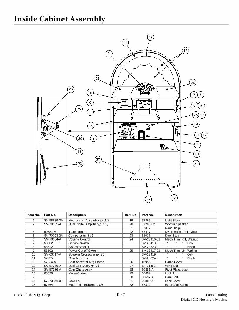
Rock-Ola® Mfg. Corp. Parts Catalog Digital CD Nostalgic Models
K - 7
Inside Cabinet Assembly
Item No. Part No. Description Item No. Part No. Description
1 SV-58689-3A Mechanism Assembly (p. 11) 19 57365 Light Block 2 SV-70135-A Dual Digital Amplifier (p. 13 ) 20 57288-02 Woofer Speaker - 21 57377 Door Hinge 4 60681-A Transformer 22 57477 Nylon Base Tack Glide 5 SV-70003-2A Computer (p. 14 ) 23 61021 Door Stop 6 SV-70004-A Volume Control 24 SV-23416-01 Mech Trim, RH, Walnut 7 58602 Service Switch SV-23418 “ “ “ Oak 8 58622 Switch Bracket SV-23823 “ “ “ Black 9 58602 Power Cut off Switch 25 SV-23417-01 Mech Trim, LH, Walnut
10 SV-60717-A Speaker Crossover (p. 8 ) SV-23419 “ “ “ Oak 11 57335 Coin Acceptor SV-23824 “ “ “ Black 12 57334-A Coin Acceptor Mtg Frame 26 46956 Cable Cover 13 SV-57366-A Dual Lock Assy (p. 8 ) 27 ST-01352 Wing Nut 14 SV-57336-A Coin Chute Assy 28 60881-A Pivot Plate, Lock 15 60596 Mural/Curtain 29 60699 Lock Arm - 30 60697-A Cam Bolt
17 57373-24500 Gold Foil 31 60880-A Lock Lever 18 57364 Mech Trim Bracket (2 pl) 32 57372 Extension Spring

Rock-Ola® Mfg. Corp. Parts Catalog Digital CD Nostalgic Models
K - 8
Dual Lock Assembly SV‐ 57366‐A
Item No. Part No. Description
10 57368 Dual Lock Side 11 57369 Shoulder Screw 12 57367 Dual Lock Guide
Crossover PCB Assembly SV‐60717‐A
Qty Part No. Description Ref. Des. 2 58942 Coil .8mH L1, L4 2 58943 Coil 1.25mH L2, L3 2 58948 Cap 47uf C2, C7 2 58949 Cap 22uf C4, C5 2 58950 Cap 5.6uf C1, C8 2 58944 Cap 3.9uf C3, C6 2 58933 Res 10 ohm, 5W, 10% R2, R3 2 60767 Res 62 ohm, 5W, 10% R1, R4 2 60766 Res 39 ohm, 5W, 10% R5, R6 1 58947 Header 12 pin Right Angle J1

Rock-Ola® Mfg. Corp. Parts Catalog Digital CD Nostalgic Models
K - 9
Outside Cabinet Assembly
Item No. Part No. Description 1 48982 Coin Return Cup 2 49041 Coin Return Flap 3 49040 Coin Cup Mtg Brkt 4 ST-04843 Flatwasher 5 ST-09722 Screw 8x3/4 Hex Flg 6 49062 Cash Bag 7 49060 Cash Door Frame SV-51019-7A Cash Box Door Assy
8 49061 Cash Box Door 9 ST-10441 Lock (w/ key)
10 50796-01 Cam Bolt 11 43293 Button Bumper
12 57292-A Reject Shaft Assembly 13 57237 Reject Shaft 14 ST-11320 Nylon Washer 15 ST-04565 Screw 8-32x1 Pan Hd 16 45474 Spring 17 ST-11352 Spacer 18 ST-03139 Washer 19 ST-07240 Screw 8-32x3/4 Flat Hd 20 See “Kits and Accessories”
for items shipped in the cash box (page 21)

Rock-Ola® Mfg. Corp. Parts Catalog Digital CD Nostalgic Models
K - 10
Item No. Part No. Description Item No. Part No. Description
1 SV-49997-3A Handle & Bracket Assy 3 ST-11296 Lock & Key 2 57376-18500 Mirror Strips 18 1/2” 4 ST-11296-K Key only
CD‐8 Bubbler Base Assembly
SV‐57322‐A
Item No. Part No. Description
1 58317 Side Metal RH 2 58316 Side Metal LH 3 57323 Front Corner Metal RH 4 57324 Front Corner Metal LH 5 57326 Lower Front Corner Metal 6 57325 Front Center Base Metal 7 ST-06030-04 Caster, Double Wheel

Rock-Ola® Mfg. Corp. Parts Catalog Digital CD Nostalgic Models
K - 11
Mechanism Assembly
31A
31C 31B

Rock-Ola® Mfg. Corp. Parts Catalog Digital CD Nostalgic Models
K - 12
Item No. Part No. Description Item No. Part No. Description 1 SV-70003-2A Computer Assy (See page 14) 30 SV-59241-3A CD Pro 2M Player Assy 2 SV-57189-A Gripper Assembly (See below) 31A 59954 Hub Insert 3 57062-2A Mechanism Top Chassis Assy 31B 58639 Spring 4 58476 Main Chassis 31C 57051 Standoff 5 57161-01 Mech End Plate 6 58677 Mechanism Base Frame 32 58540-A Audio to CD Player Cable 7 SV-55941-1A D.C. Gear Motor Assy 33 57063-1A CD Player Mtg Bracket 8 57273 CD Hold Down Bracket 34 59071 Grommet 9 58544 Mounting Plate, RCA Jack 35 57156 Magazine Main Shaft
10 57167 Base Coil Spring 36 59140 Mech Warning label 11 57168 Nylon Spring Insert 12 57157 Gripper Arm Rest Bracket SV-57188-A Magazine Assembly 13 57159 Opto Mounting Plate M1 56016 Hub Front 14 57060-A Opto Slide Bracket Assy M2 56017 Hub Rear 15 58687-A Mech Opto Cable Assy M3 56348-1A Separator Wire Assy 16 57154 Switch Mounting Bracket M4 56283 Magazine Label 17 43414-01 Snap Switch M5 57187-A Cover Magazine Assy 18 57170 Steel Band M6 50308-01 Main Bearing 19 57153 Gripper Motor Mtg Bracket M7 ST-09264 Retaining Ring 20 55843 Mag. Motor Mtg Bracket M8 ST-10561 10x1/2x Flg “B” 21 57071 Nylon Hole Plug M9 57172 Spacer 22 58679 Momentary Switch M10 55278-02 Encoder Disc 23 57165 Standoff M11 ST-11282 10x1 1/4 Hex Flg “B” - M12 ST-04813 Flatwasher
25 57070 Clamper Spring M13 ST-09194 Retaining Ring 26 57064-1A CD Lifter Bracket Assy M14 57293 Drive Gear 27 56076 Magnet Holder M15 ST-02586 10-32x 1 1/2 Hex Flg MS 28 ST-00867 Rivet M16 56114 Spacer 29 57166-02 Clamper Plate M17 ST-08717 10-32 Hex Nut
Item No. Part No. Description Item No. Part No. Description SV-57189-A Gripper Assembly 23 56185-1A Inner Gripper Assy
1 SV-45421-03 Gripper Housing 24 54768 Spring Gripper 2 45422 Gripper Housing Bearing 3 52268-2A Brkt Gripper Rev. Rivet Assy 4 ST-09747 Screw 10-32x3/8 Hex Flg 5 ST-09720 Screw 10-32x1/2 Hex Flg 6 34315-07 Gripper Spider - 8 34399 Trunnion Shaft 9 34877 Trunnion Shaft Button 10 34312-02 Gripper Turnover Gear 11 34311-04 Gripper Release Gear 12 ST-03150 Flatwasher 13 57169 Cam 14 ST-04881 Flatwasher 15 ST-06535 Screw 8-32x5/8 Phil Pan Hd 16 56434-A Gripper Shaft Assy 17 34310-01 Gripper Shaft Gear 18 ST-00534 Spiral Pin Medium duty 19 34929 Gripper Shaft Thrust Washer 20 ST-04828 Spring Washer 21 34323-8A Cam Gripper Arm Rev. Assy 22 56015-1A Gripper Arm Assy

Rock-Ola® Mfg. Corp. Parts Catalog Digital CD Nostalgic Models
K - 13
Electronic Components
Dual Digital Amplifier SV‐70135‐A
Item No. Part No. Description 1 60621-A Chassis, Dual Amp 2 40678-09500 Rubber Cushion 9.5” 3 58641 Switch, Corcom
4 ST-04346 Fuse, 8 Amp, 250v, fast blow (1 req) (Domestic)
ST-11141 Fuse, 5A, 250V, fast blow (2 req) (Export)
5 60438-A Harness, Amp Main Power 6 60622-A Cover, Dual Amp 7 SV-60435-A PCB, Digital Power Supply 8 SV-60441-1A PCB, Digital Pre Amp 9 SV-60429-1A PCB, Digital Aux Amp
10 SV-60442-A PCB, Digital Power Amp 11 ST-11549 Standoff, 4-40 x 1/4” 12 60647-A Harness, Power Amp 13 60648-A Harness, Audio Output Panel 14 60649-A Harness, Aux Amp Input 15 60643 Transformer Support Audio 16 SV-60455-1A Audio Output Panel PCB 17 ST-11429 Thumb Screw 6-32x3/8 (4 places)
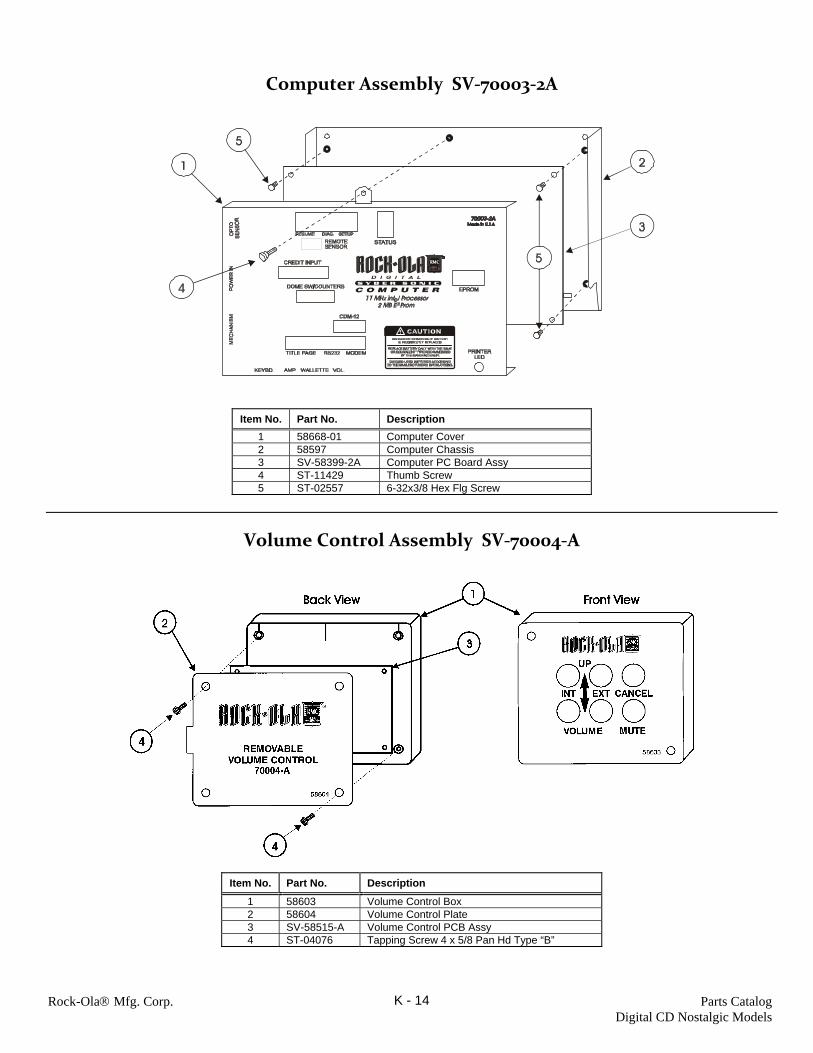
Rock-Ola® Mfg. Corp. Parts Catalog Digital CD Nostalgic Models
K - 14
Computer Assembly SV‐70003‐2A
Item No. Part No. Description
1 58668-01 Computer Cover 2 58597 Computer Chassis 3 SV-58399-2A Computer PC Board Assy 4 ST-11429 Thumb Screw 5 ST-02557 6-32x3/8 Hex Flg Screw
Volume Control Assembly SV‐70004‐A
Item No. Part No. Description
1 58603 Volume Control Box 2 58604 Volume Control Plate 3 SV-58515-A Volume Control PCB Assy 4 ST-04076 Tapping Screw 4 x 5/8 Pan Hd Type “B”

Rock-Ola® Mfg. Corp. Parts Catalog Digital CD Nostalgic Models
K - 15
Cables

Rock-Ola® Mfg. Corp. Parts Catalog Digital CD Nostalgic Models
K - 16

Rock-Ola® Mfg. Corp. Parts Catalog Digital CD Nostalgic Models
K - 17
Speaker Harness, 61889-A-LF

Rock-Ola® Mfg. Corp. Parts Catalog Digital CD Nostalgic Models
K - 18
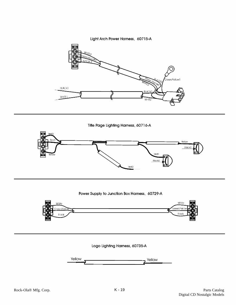
Rock-Ola® Mfg. Corp. Parts Catalog Digital CD Nostalgic Models
K - 19

Rock-Ola® Mfg. Corp. Parts Catalog Digital CD Nostalgic Models
K - 20

Rock-Ola® Mfg. Corp. Parts Catalog Digital CD Nostalgic Models
K - 21
Kits and Accessories
PART NO. DESCRIPTION Items shipped in the cash box (I.R. Remote Control Package) 61467- A I.R. Remote Control, Deluxe SV-60046-A I.R. Remote Receiver Assembly SV-59891-A I.R. Receiving Interface PCB Assembly 58810 Remote Sensor Enclosure ST-09728 Screw, 4-40 x 1/4 Phil Pan Hd Sw. 58789-A I.R. Remote Harness 59164-03 Installation Instructions Service Envelope: (contains the following:) 56202-02 Pricing Sheet 60753 Title Strips, Single (25) 57279-02 Title Strips, Double (34) 60761 Operation & Service Manual with Parts Catalog 60511-02 Quick Find Reference Programming Sheet 60457-02 “ Spanish (for Mexico) 57022-03 Warranty Card (Domestic) 58180-02 “ (for Mexico) 59515 “ (for Export) 55004 Application Form 56141 Number Strip 60670-01 Price Card, Blank (Domestic) 60683 Decal, DBA $1 & $1/2/5 (Domestic) 60685-A Harness, Speaker Adaptor 60704-A Terminal Kit Optional Kits: 02379-02 Yoga Microphone Kit 02451 Serviceman’s Kit 02410 Counter Kit 02414 Volume Accessory Unit Kit 02450 Audio Distribution Package, Digital Amp 02417-02 Telecommunications Kit 02436 Mars Dollar Bill Acceptor Kit 02465 iPod® Kit
iPod® is a trademark of Apple Computer Corp.