this is a professional dmx tester with many useful ... · this is a professional dmx tester with...
TRANSCRIPT

1 Product Description
This is a Professional DMX Tester with many useful functions. There are 8 main function modes provided for user’s application: DMX packet test, DMX data—RX, DMX data—TX, Moving light, Save Cue (Scene), Cable test, MIDI data—RX and System setup. The unit also offers built-in chargeable batteries for user’s convenient operation. To optimize the performance of this product, please read this Manual carefully to familiarize yourself with the basic operations.
2 Notice Information
When unpacking, please check the unit is not damaged. If something wrong has happened to this product, contact the local dealer immediately. All rights reserved. No part of this manual included with this product can be reproduced or transmitted in any form, by any means or for any purpose, without authorized permission.
3 Prod
1. LC2. M3. Po4. DM5. DM6. M
Warning • Keep the unit dry, do not expose it to water or high levels of humid. • Do not open this unit, there is no user serviceable part inside. • Turn off the power if not using this unit for a long time. • Any strong shocks or vibration may result in malfunction. • Do not attempt to dismantle or modify the unit. • This unit must only be operated by adults, do not allow children to play with it.
uct View
D Display: To display relevant menus, settings or function modes. ulti-Selector: To select desired menus, function modes or used to finish relevant settings. wer Input: To input main power via this port. X IN: 3-pin & 5-pin male XLR sockets. X OUT: 3-pin & 5-pin female XLR sockets.
IDI IN: MIDI signal can be input via this male socket.
24-004-1247 Rev 1.0

4 Operation Guide
This product can be used in various lighting conditions to meet user’s requirement. It provides a 4×20 characters LCD which gives user more convenience for easier operation.
User can rotate the multi-selector gently to enter relevant function modes or to achieve desired settings. Rotating the multi-selector clockwise can select further menu or increase relevant value, while rotating the multi-selector anti-clockwise can select the previous menu or decrease relevant value. Press the multi-selector can enter the selected menu or save your setting.
The power of this unit can be supplied by the built-in chargeable batteries or a DC 9V adapter. The battery will be charged automatically when using the DC 9V adapter for power supply. Charging the battery fully needs 3-5 hours or so, and the battery can supply the unit for almost 6-8 hours. Turn on the power switch, the unit will be powered on and the LCD display will show you as below :
If there is no timely operation upon the multi-selector within about 5 seconds, the above menu will automatically go forward to the main menu of function modes display:
Rotate the multi-selector clockwise to view the next page Rotate the multi-selector anti-clockwise to return
4.1 DMX packet test
Use the multi-selector to select the DMX packet test item, then press the multi-selector to enter.
Press the multi-selector Press again to return
• User can use the multi-selector to select and enter relevant submenus of Data format, Data timing and Data level (volt). If there is no effective signal input, entering any one of these three submenus, the LCD will show you the same information as below:
< DMX packet test: Receive no signal ?
=== SHOWTEC === DMX TESTER
REV 1.23 Copyright 2004 >
↑ Save Cue (Scene) > Cable test > MIDI data -- RX > System setup >
< DMX packet test : > 1. Data format > 2. Data timing > 3. Data level (Volt) >
< DMX packet test > DMX data--RX > DMX data—TX >↓ Moving light >
< DMX packet test > DMX data--RX > DMX data—TX >↓ Moving light >
2

• Use the multi-selector to select the” ?”, then press the multi-selector, the LCD will show you details:
(If there is an effective input signal for this unit, user can then do some DMX packet tests as below)
4.1.1 Data format
• Use the multi-selector to select the Data format item, and press the multi-selector to view the total channels of external operator and the states of BREAK when receiving signals. The LCD will show you the channel information of the connected DMX operator.
( For example, here the connected external DMX operator is the DC-1216II of NCW )
< T-BOX 512 tester help No signal or signal not complying with USITT DMX-512 (1990)
< Data format : ? RX-Chan: 192 Break: --OK-- Signal present
total channels of DC-1216II
• Use the multi-selector to select the” ?”, then press the multi-selector for help information, LCD will show you as below:
< Data format : Indication of --OK-- means: Received signal is good
(Pressing the multi-selector again will return to the previous menu)
4.1.2 Data timing
• Use the multi-selector to select the Data timing item, and press the multi-selector to enter the further menu. User can view relevant parameters, including BREAK, MaB, START CODE, CHAN TIME and Period Time. The LCD will show you relevant information:
( Here the connected DMX operator is also DC-1216II. )
All the parameters can be shown here.
< Data timing : ? BK: 135μS MaB: 016μS StartCode : 000 dec
Chan. Time : 053μs >
3
• Select the “>”, and press the multi-selector for further information, LCD-display will show you “Period : 036 ms” on the fourth line of the current display.
• Use the multi-selector to select the” ?”, then press the multi-selector for help information, LCD will show you as below:
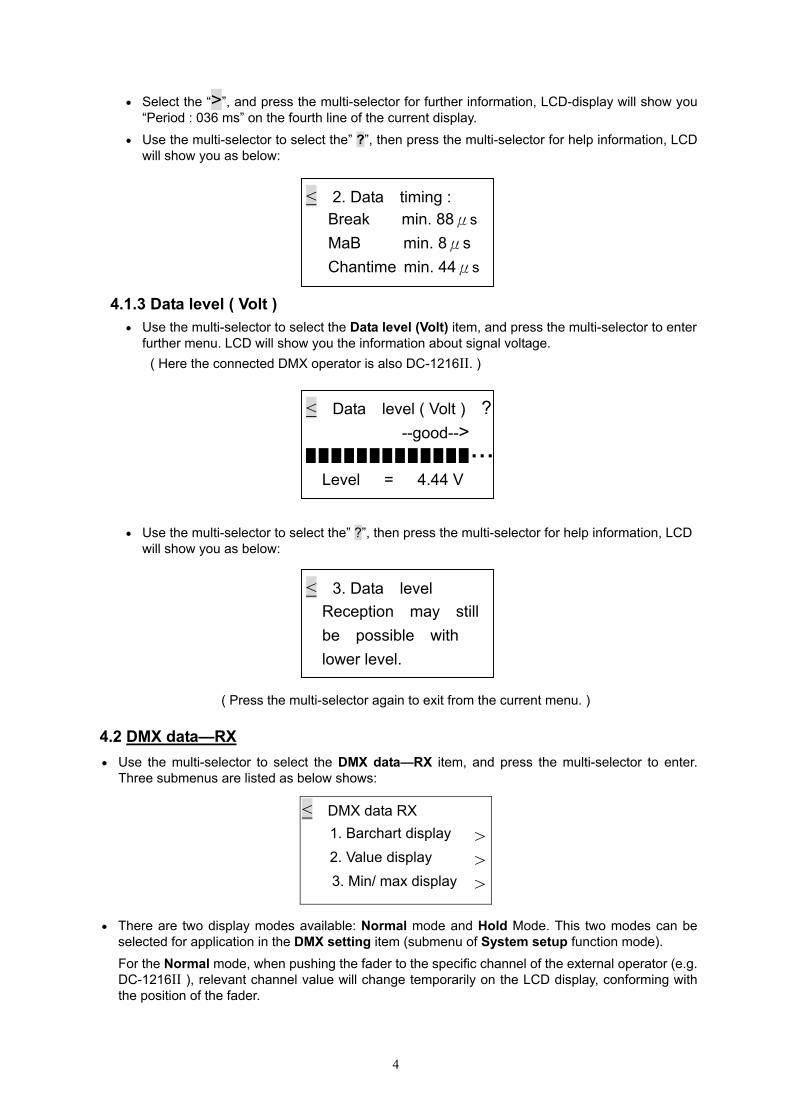
4.1.3 Data level ( Volt ) • Use the multi-selector to select the Data level (Volt) item, and press the multi-selector to enter
further menu. LCD will show you the information about signal voltage. ( Here the connected DMX operator is also DC-1216II. )
• Use the multi-selector to select the” ?”, then press the multi-selector for help information, LCD will show you as below:
( Press the multi-selector again to exit from the current menu. )
4.2 DMX data—RX • Use the multi-selector to select the DMX data—RX item, and press the multi-selector to enter.
Three submenus are listed as below shows:
< DMX data RX 1. Barchart display 2. Value display 3. Min/ max display
>>>
< 3. Data level Reception may still be possible with lower level.
< Data level ( Volt ) ? --good--> █ █ █ █ █ █ █ █ █ █ █ █ █ ▪ ▪ ▪
Level = 4.44 V
< 2. Data timing : Break min. 88μs MaB min. 8μs Chantime min. 44μs
• There are two display modes available: Normal mode and Hold Mode. This two modes can be selected for application in the DMX setting item (submenu of System setup function mode). For the Normal mode, when pushing the fader to the specific channel of the external operator (e.g. DC-1216II ), relevant channel value will change temporarily on the LCD display, conforming with the position of the fader.
4

For the Hold mode, when pushing the fader to the specific channel of the external operator (e.g. DC-1216II ), only the adjustment of higher channel value can be held and displayed on the LCD. Adjustment of lower value will be of no effect in this Hold mode.
4.2.1 Barchart display • User can use the multi-selector to enter the Barchart display submenu. If there is no signal input,
the LCD will show you empty information like below:
< RX Channel : 000 ?> 001 : xxxxx xxxxx 011 : xxxxx xxxxx 021 : xxxxx xxxxx
Each line on the LCD display indicates the values of totally 10 channels. And user can use the multi-selector to browse and view the values of other channels.
• If there is an effective input signal to this unit, the LCD will show as the following barchart display:
< RX Channel : 192 ? > 001 : 011 : 021 :
• Select the” ?”, then press the multi-selector for help information, LCD will show you as below:
< 1. Barchart display chan level
x = no signal – = no data
( Each barchart indicates different values ) 4.2.2 Value display
• Value display can be done in three patterns: Decimal, Hexadecimal or Percent. These three patterns can be selected as user’s requirement in the Display setting item (submenu of the System setup function mode).
• Use the multi-selector to enter the Value display menu. If there is no effective signal input, the LCD will show you empty information as below:
< RX Channel 1 : 000 ? Start Channel : 001 > --- --- --- --- --- > --- --- --- --- ---
The default channel value is 000 and the start channel is normally 001. To change the start channel, user can select “>” at the right side of the LCD screen, press the multi-selector and then rotate it to change the channels from 001 to 512. Press the multi-selector again to confirm your setting.
5

• If there is an effective input signal, the LCD display will show you like the following diagram:
< RX Channel : 192 ? Start Channel : 001 > 253 255 255 000 000 > 000 000 000 000 000
User can select the “>” at the left side of the LCD screen, and then press the multi-selector to select decimal, hexadecimal or percent display mode as requirement. The displayed value of the relative channel will be temporarily changed according to the new setting.
• Select the” ?”, then press the multi-selector for help information, LCD will show you as below: 4.2.3 Min / max display
• In this menu, the minimum valueRelevant values will comply withave set for use.
Suppose that you have set the p
• If the signal input has been rece
To browse and view the value odisplay. press the multi-selector,
Note: Pressing the “>” near the and the max value will be changrelevant channel).
< 2. Value display Display ten number in decimal, hexadeci- mal or percent
, typical value and maximum value can be displayed on the screen. h the decimal, hexadecimal or percent display mode, which you
ercent display mode, if there is no signal input, LCD will show you:
< RX Channel : 000 Chan. min typ max
>001 --- --- --- % >Count at : xxxxx Sec
ived correctly, LCD display will show you the follow diagram:
Time counter for reference. (Sec=second)
Total channels
< RX Channel : 192 Chan. min typ max >001 000 28 70 % >Count at : 00010 Secf each channel, user can select the “>” at the third line on the LCD and then rotate it to view desired values.
Count at item, the time will return to 0 second level. The min value ed to the same level as the present typ value (the present value of
6

4.3 DMX data—TX
• In this function mode, relevant parameters can be set for data sending. While accessing this DMX data—TX menu, the new coming DMX signal will be disabled. You will be allowed to set the levels temporarily for the intended channels, and also have priority to transmit the Cue (Scene) at a set rate. There are only 15 Cues available.
• User can use the multi-selector to enter the DMX data—TX function mode, LCD will show you:
< 1. 512 Channel > 2. Single Channel > 3. Cue/Memory > 4. Run Cues (Scenes) >
4.3.1 512 Channel • In this 512 Channel submenu, 512 channels can be displayed and be used for temporary
adjustment. The actual channel value can be held. User can use the multi-selector to enter this item, LCD will show you like below:
< 1. 512 Channel ? Mode : Modify mode
Chan : 001 >↓ Data : 000 = 000 % >
To adjust the temporary value of the desired channel, first enable the multi-selector to “>” at the third line on the LCD screen. Then adjust the "Data" at the fourth line. Relevant value can be displayed in decimal and percent patterns.
• User can scroll the multi-selector to enter the next page. LCD will show you like below:
C
C
Relevaselecto
• If user multi-sethere wchanne
• Select
↑ Channel : > [ 001 -- 010 ]000 000 000 000 000 Channel 10
hannel 1
000 000 000 000 000 Clear All >
hannel 2
nt values can be set availably. Move the cursor to the desired chanr to set the value. After your setting, press the multi-selector to confir
want to set all channels to be “000”, just activate the “Clear Alllector. Select the “>” at the bottom right corner of the screen, pressill be a “Clearing” information appears on the LCD display. About l values will be changed as “000”.
the” ?”, then press the multi-selector for help information, LCD will sh
< 1. 512 Channel Modify = Each channel will hold its preset value
7
nel, then use the multi- m your operation.
” function by using the the multi-selector, then 2 seconds later, all the
ow you as below:

4.3.2 Single Channel • In this Single Channel menu, there are Auto Speed, Channel, Mode and Level items which can
be set as user’s requirement. The Speed level can be set from 01 to 10. Fade Only, Fade Fine, Auto On/ Off, Ramping and Stop functions can be selected in the Mode item. To be concerned.
Note: Only in the Auto On/Off mode, or in the Ramping mode can the Auto speed function be available. When in other modes, the Auto speed function will be of no effect.
• When entered the Single channel menu, LCD will show you like the following diagram:
? >>>
• Select the” ?”, then press the m
4.3.3 Cue / Memory • In this Cue/Memory menu, the r
for use. Using the multi-selector
Use the multi-selector to changemulti-selector to confirm your op
• Select the” ?”, then press the m
< Auto Speed : 01 > Chan : 001 Mode : Fader Only Level : 000 = 000 %
ulti-selector for help information, LCD will show you as below:
< 2. Single Channel 512 data is same, or one data is special the other is zero
eceived data can be saved as Cues. There are 15 Cues available to enter this menu, LCD will show you like this:
< 3. TX data as Cue ? Cue number: 001 >
the Cue number from 001 to 015. After your setting, press the eration. ulti-selector for help information, LCD will show you as below:
< The 512 data of cue come from RX or from old cue which can be modified in ‘TX-512’
8

4.3.4 Run Cues ( Scenes ) • When entered this menu, user can transmit Cues continuously at a specific rate. LCD shows you:
Default End Cue No.Default Speed rate
The default start cue is Cue 1. multi-selector.
• Select the” ?”, then press the m
4.4 Moving light
• When entered this Moving ligh
• User can set the function of eapreset to meet your requiremenattachment of the information focan adjust relevant parameters
4.4.1 Library setting • To set the light function of desire
will show you the fixture numbe10 kinds of fixtures in all for reselected availably.
< 4. Run Cues(Scenes) ? Total Cue : 1 End Cue: 15 > Speed rate : 01 >
User can adjust the end Cue No. and speed rate ( 01 -10 ) by the
ulti-selector for help information, LCD will show you as below:
< 4. Run Cues(Scenes) From cue 1 to the end cue continually in speed rate
t function mode, the LCD-display will show you as below:
< Moving light : 1. Library setting > 2. Play mode >
ch fixture channel complying with the preset library. The library is t in general. If you want to use your own library, please mail us an r updating. For more tests, user can use the “library settings” and
of each channel in the Play mode.
d channel, user can use the multi-selector to enter this menu. LCD r, name and functions of each channel. There are 36 channels and levant settings. And each channel has 29 effect functions to be
< 1. Library setting >
FX No. : 01 NAME_1 >
01 Color 02 Cyan 03 Dimmer 04 Effect
Library stored
9

• User can select desired fixture and set the fixture name. Relevant function of each channel can also be set by using the multi-selector. After your setting, user can select the “>” at the top right corner of the screen, then press the multi-selector to confirm.
• To change the fixture name, move the cursor to the“>” at the second line on the screen, and press the multi-selector. Then user can use the multi-selector to set relevant characters as desire. After that, press the multi-selector to confirm your setting.
• To change the lighting function of desired channel, for example, move the cursor to 01, and press the multi-selector. Then use the multi-selector to set desired function item. After your setting, press the multi-selector again to confirm your operation.
• User can rotate the multi-selector to view the next page:
05 Focus 06 Frost 07 Gobo 08 Gobo rot 09 Inten'ty 10 Iris 11 Lamp 12 Laser
21 Speed CG 23 Speed PT 25 Strobe 27 Tilt Fine
22 Speed P 24 Speed T 26 Tilt 28 Yellow
14 Pan 16 Prism 18 Rot spel 20 Special
13 Magenta 15 Pan fine 17 Reset 19 Shutter
30 -------- 32 -------- 34 Cyan 36 Frost
29 Zoom 31 ----------------- 33 Color 35 Dimmer
If user want to set lighting function of this unit for testing other lighting equipments, you must make sure the parameters you have set must be complying with the device to be tested.
4.4.2 Play mode • In this menu, user can test the fixtures by using the previous library settings. Use the multi-selector
to enter the Play mode, LCD-display will show you like below:
> > >
< 2. Play mode FX No. : 01 NAME_1 Start address : 001
Func. : Color > 000
Part 2
As the above diagram shows, user can move the item with the multi-selector. Move the cursor to “>”can be adjusted from 001 to 512. Suppose that theselected as “Pan”, complying with the specific fixturotate horizontally at your disposal.
Note: User can move the cursor to the “>” at the srelevant fixtures or to select the CH-TEST(channeitem and have pressed the multi-selector to confirmappear at the fourth line of the screen. That meachannel values can be set as user’s desire.
10
Part 1
cursor to “>” ( part 1) to select desired function ( part 2) to set desired value. The Start address Start address is set as “001”, and the function is re. Then change the level, the fixture arms will
econd line, and use the multi-selector to select l test) item. If user have chosen the CH-TEST . The information of “Func. : ch_01 >000>” will ns relevant channels (up to 36 channels) and

4.5 Save Cue (Scene)
• User can use the multi-selector to enter this function mode, LCD will show you like below:
< Save Cue ( Scene ) as Cue no. : 001 Confirm
• The default Cue number is 001, the Cue number can requirement. Select the “>” at the third line on the screenyour setting.
Note: Select the “>” at the second line, press the multi-sel“Clear all Cues” information appears on the screen. Thecursor to the “>” at the third line, press the multi-selectorYes> No> ”. User can then press the Yes “>” to conselect Yes and press the multi-selector for confirmation, th
• Select the” ?”, then press the multi-selector for help inform
< Save Cue (Scene) The cue with 512 da -ta can be stored to memory or clear cues
4.6 Cable test
• In this function mode, user can test the cables. The cable analog mode. When entered this function mode, LCD will
< Analog cable test Connect cable to both sockets, press
Start !
• The default test mode is analog mode. Select the “>” at theswitch between the digital mode and the analog mode. Uscable connection. Make sure the connection is OK, then sCable Test. If the cable works well, LCD will show you:
11
? > >
be changed from 001 to 015 as user’s , and press the multi-selector to confirm
ector, then scroll the multi-selector till the n press the multi-selector and move the again, the LCD will ask you “ Be sure? firm, Press the No “>” to cancel. If you e LCD will show you “Stored OK!”
ation, LCD will show you as below:
test can be done in digital mode or show you as below:
>
>
first line, then press the multi-selector to e standard DMX Input/Output sockets for elect the “>” at the fourth line to start the
< --- Cable Test --- Result successful ! - > TEST OK !

• If the cable does not work well, LCD-display will show you as below:
< --- Cable Test --- Result: -> Cable not OK
4.7 MIDI data—RX
• In this function mode, the MIDI data can be tested. ( MIDI signal can be input via a 5-pin male XLR socket provided by this unit). If the cable isn’t connected well, when entered this function mode, LCD will show you:
• If there is effective signal input
4.8 System setup • When entered this function mo
( User can ent
4.8.1 DMX setting • Using the multi-selector t
< MIDI data – RX: $
, and the cables are connected well, the LCD will show you like this:
“FE” means NULL signal
< MIDI data -- RX $ FE FE FE FE FE FE FE 43 00 45 00 FE 90 43 00 FE FE FE
de, the LCD-display will show you as below:
< System setup : 1. DMX setting 2. English 3. Display setting
er relevant submenu by u
o enter this submenu, LCD
12
> > >
sing the multi-selector )
will show you like this:
> > > >
< Start code TX : 000 Display : Normal Input Pin : -2 : +3 ? Confirm

• The Start Code can be changed from 000 to 255 . The Normal mode and Hold mode can be selected by the multi-selector as user’s requirement .
• The “Input Pin” can be changed by the multi-selector between “-2 +3” and “+2 -3”. However, this adjustment will comply with the receiving signals, which can be normal or reverse.
• User can select the “>” at the fourth line on the screen, then press the multi-selector to confirm your settings. If you select the” ?”, and then press the multi-selector for help information, LCD will show you as below:
< 1. DMX setting Startcode TX : 00-FF Display Hold mode Input normal : -2 +3
4.8.2 English
• This unit supports 5 languages for convenient operation, including English, German, Spanish, French and Italy. The default language version is English. User can use the multi-selector to choose the desired language version, and then press the multi-selector to confirm.
Note: The system language can be only changed temporarily when powered on. If user restart the unit, the system language is still the English version.
• If user want to keep your language version setting always available for use, you can store the setting into memory. For example, if you want to change the language version as German, firstly you must set the language, and then use the multi-selector to enter the DMX setting submenu or the Display setting submenu. After that, select the “>” at the fourth line of the screen, press the multi-selector to confirm your setting. Then the German language version will be always available for use even if you restart the unit.
4.8.3 Display setting
• User can use the multi-selector to enter the Display setting menu, the LCD-display will show you:
>
• The Contrast level of brightnes
The Back Light of the unit can the back light as “on” functiomulti-selector again, the back function, then the back light will
The Display mode can be selec
Note: All the above settings casettings for available usage, yousettings respectively. (If there dino effect when restart the unit n
< Contrast_ level : 06 Back Light : off Display : percent ? Confirm
s can be set from 01 to 10 a
be set as “on” or “off” statusn, then the back light willlight will light up immediatebe always in the “off” status.
ted as Decimal, Hexadecim
n be done by using the mu must select the “>” at the fo
dn’t confirm relevant setting,ext time.)
13
> > >
s user’s requirement.
by using the multi-selector. If user set go out in 15 seconds. Trigger the ly. If user set the back light as “off”
al or Percent.
lti-selector. If user want to save your urth line on the screen to confirm your
the settings will be canceled and be of

• User can select the” ?”, and press the multi-selector for help information, LCD will show you more details as the following display:
< 3. Display setting Contrast_level : 1-10 Back Light : On./Off dec, hex or % data
5 Specifications
Power supply …………………………………………………………………………………..DC 9V, 500mA DMX In………………………………………………………………………3-pin & 5-pin male XLR sockets DMX Out …………………………………………………………………3-pin & 5-pin female XLR sockets MIDI Input……………………………………………………………….….…….………...XLR socket (male) Dimensions……………………….…………………………………………………………...200×160×55mm Weight…………………………………………………………………………….……………………….1.2 kg
14