this document was prepared in conjunction with work
TRANSCRIPT

Contract No: This document was prepared in conjunction with work accomplished under Contract No. DE-AC09-08SR22470 with the U.S. Department of Energy. Disclaimer: This work was prepared under an agreement with and funded by the U.S. Government. Neither the U. S. Government or its employees, nor any of its contractors, subcontractors or their employees, makes any express or implied: 1. warranty or assumes any legal liability for the accuracy, completeness, or for the use or results of such use of any information, product, or process disclosed; or 2. representation that such use or results of such use would not infringe privately owned rights; or 3. endorsement or recommendation of any specifically identified commercial product, process, or service. Any views and opinions of authors expressed in this work do not necessarily state or reflect those of the United States Government, or its contractors, or subcontractors.

SRNL-STI-2009-00731
To be submitted for publication in Journal of Nuclear Materials Management, special edition focused on the engineering and science supporting the safe storage of plutonium materials
Closure Weld Development for 3013 Outer Containers
W. L. Daugherty, S. R. Howard, K. D. Peterson, M. W. Stokes (Savannah River National Laboratory), G. R. Cannell (Fluor Enterprises, Inc.), and S. A. Breshears (Los Alamos National Laboratory)
Abstract
Excess plutonium materials in the DOE complex are packaged and stored in accordance with DOE-STD-3013. This standard specifies requirements for the stabilization of such materials and subsequent packaging in dual nested seal-welded containers. Austenitic stainless steels have been selected for container fabrication. The inner 3013 container provides contamination control while the outer 3013 container is the primary containmentvessel and is the focus of this paper. Each packaging site chose a process for seal welding the outer 3013 containers in accordance with its needs and expertise. The two processes chosen for weld closure were laser beam welding (LBW) and gas tungsten arc welding (GTAW). Following development efforts, each system was qualified in accordance with DOE-STD-3013 prior to production use.
The 3013 outer container closure weld joint was designed to accommodate the characteristics of a laser weld. This aspect of the joint design necessitated some innovative process and equipment considerations in the application of the GTAW process. Details of the weld requirements and the development processes are presentedand several potential enhancements for the GTAW system are described.
Introduction and Background
DOE-STD-3013 [1] governs the stabilization and packaging of plutonium-bearing materials within the DOE Complex. This standard specifies that the material be stored in two nested containers which are fabricated from a ductile, corrosion resistant metal or alloy and seal welded. Austenitic stainless steels (Types 304L and 316L) were selected for container fabrication. Furthermore, material shipped to the Savannah River Site for storage must meet requirements [2] in addition to those specified in the 3013 standard. The integrity of containment is assured through the container design, material specification and fabrication requirements, closure weld integrity, and post-closure testing. This paper focuses on the closure weld integrity for the outer container, and the weld systems that have been developed to provide an acceptable closure weld.
The corner joint of the 3013 outer container is formed by pressing an interference-fit (nominally 0.04 mm interference) lid into the container, creating a square-groove, weld preparation (Figure 1). The closure weld is made autogenously (without addition of filler).

SRNL-STI-2009-00731
Description of Closure Weld Systems
Five sites within the DOE complex have packaged plutonium-bearing materials in accordance with DOE-STD-3013. Rocky Flats Environmental Technology Site (RFETS)and Lawrence Livermore National Laboratory (LLNL) used a laser beam welding (LBW) system, while Hanford Site (Hanford), Savannah River Site (SRS) and Los Alamos National Laboratory (LANL) used a gas tungsten arc welding (GTAW) system.
The LBW system was developed by British Nuclear Fuels Limited (BNFL), which also established the design details for the outer container. As the first site to begin packaging excess plutonium material, RFETS used the BNFL system which was originally envisioned for use throughout the DOE complex. However, because of site to site differences in expertise and economic considerations, alternate weld closure solutions were developed and deployed. The weld closure systems that emerged include:
1) Rocky Flats Environmental Technology Site: The RFETS system was a fully automated, glovebox enclosed system that integrated plutonium stabilization operations with packaging the material in both the 3013 inner and outer containers. The LBW system used a 2 kW Nd:YAG laser for both the inner and outer container closure welds. A packaging control system controlled the closure weld process, and a data management system provided some data collection capability. [3, 4]
2) Lawrence Livermore National Laboratory: LLNL chose to use the same laser technology, but incorporated several modifications. The LLNL system used much less automation, and changed some of the weld parameters (slower speed, increased power) to improve the weld bead shape. [4, 5]
3) Hanford Site: Hanford decided to pursue the development of a GTAW system, and contracted with Savannah River National Laboratory (SRNL) for this effort. It was believed that a “hands-on”, less complex system would provide a more robust process (i.e. more forgiving of minor process variations), which would better support Hanford’s plutonium packaging cost and schedule requirements.
The Hanford system consisted of standard off-the-shelf orbital GTAW equipment modified to accommodate the outer container design, including the addition of a copper alloy chill block, modifications to the clamping system, the use of a thoriated (2% ThO2) tungsten electrode and other mechanical features. In addition, a data acquisition system (DAS) was developed [6, 7]. The DAS acquired information to assure that proper process control was maintained throughout the welding process. The actual weld sequence was programmed to proceed automatically, but all other mechanical operations were performed manually.

SRNL-STI-2009-00731
4) Savannah River Site: SRS used the GTAW technology that was developed for Hanford, with several improvements based on the experience at Hanford. The system retained the same degree of manual operation and the DAS was upgraded to capture more weld process information. During initial testing, a number of weld failures (blowouts) were experienced due to the pressure developed in the container interior. Insertion of the container lid increases the internal pressure to above atmospheric and this pressure can increase further as the weld operation heats the container. Occasionally the internal pressure reached the point that a weld blowout occurred and elimination of such blowouts presented an operational challenge to the welding process. This challenge was addressed by backfilling the container with less than 760 torr (1 atm) pressure, so that inserting the interference-fit lid would create an internal pressure just above, but not significantly greater than 760 torr (1 atm).
5) Los Alamos National Laboratory: LANL developed its own closure weld systembased on GTAW technology. The LANL system used a fixture to rotate the outer container during welding. The weld head and fixture were located inside a welding enclosure (similar to a small glovebox) with a helium atmosphere. This ensured that the container was filled with 100% helium. The interference fit between the body and the lid was overcome by heating the top of the body to about 120°C (250°F) with a band heater; thermal expansion then allowed the lid to be seated manually through a gloveport.
Each of these DOE sites pursued the development and/or acquisition of a closure weld system that was consistent with their expertise, needs and available resources. Each system offered advantages, and performed the assigned mission.
Following their respective development, each of the closure weld technologies (LBW, GTAW) underwent testing to demonstrate the closure system met the requirements of References 1 and 2. This included 9.1 m (30 ft) drop tests (dropping a container onto a flat surface), 3 m (10 ft) crush tests (dropping a container onto a second container), hydrostatic proof and burst testing, metallographic and radiographic examination, and stacking (stack of multiple containers) tests. Leak tightness had to be demonstrated following the drop, crush, proof and stacking tests.
At each site, the outer container welder (OCW) underwent an initial qualification run, as required by the governing standard [2], before it was placed into production. This run consisted of completing 25 successive successful welds, and performing subsequent analysis to demonstrate the integrity of all 25 welds. This analysis included:- Visual examination of closure weld- Leak test of the sealed container- X-ray examination of the entire length of closure weld- Metallographic examination of 4 (or more) cross sections through the closure weld
Post-Weld Quality Checks

SRNL-STI-2009-00731
Once approved for production use, every container which is successfully seal welded receives several inspections to ensure its integrity. These inspections include the following:- The data acquisition system report is reviewed to verify that the weld parameters
were within established ranges.- The weld receives a visual inspection for surface flaws or discontinuities.- The container, which was filled with helium prior to welding, is placed under a
belljar for a helium leak test. Separate criteria are used to identify gross leakage and fine leakage. The leak rate must be < 2.0 E-7 std cc He / sec, per ANSI 14.5.
- In order to fit within a shipping package, the container must meet strict dimensional requirements. The height and diameter are verified to meet these requirements. (A small relaxation of the diameter requirement was approved for RFETS.)
Beyond these minimum requirements, LANL also recorded a video of each production weld, both during the weld and after the weld was completed. SRS performed digital radiography on every closure weld, to screen for unacceptable porosity or other internal defects.
As a minimum, every 25th production weld is made on a container with surrogate content. After all other inspections are completed, the lid (with the closure weld) is separated from the outer container. The closure weld is x-rayed and sectioned for required metallographic examination [2]. The x-ray examination is conducted and evaluated in accordance with ASME Section VIII, Division 1, UW-51 (7.3). The metallographic examination interrogates the weld cross section at 4 (or more) locations, and must show full penetration, be free of cracks and lack of fusion (at 10X magnification), and have a weld bead geometry in compliance with ASME Section VIII, UW-13.2 (d). RFETS received relief from the weld bead geometry requirement [4],which evolved from arc welding processes and is difficult to meet with a highly focused laser weld. This is one reason that LLNL changed the welding parameters from those used at RFETS.
Process Challenges Inherent to Each System
There are inherent differences between the LBW and GTAW systems that presented both opportunities and challenges in meeting the requirements of the 3013 closure. Some of these include:- The LBW system is more complex than a GTAW system. In the RFETS system,
several integrated functions were housed together. Activities such as content stabilization, container loading, inner can welding/cutting were interconnected, with a chain of automation that hampered reliability and increased operational difficulties. As a result, this system was unreliable and difficult to operate [3].
- The relative simplicity of the GTAW system led to lower capital and maintenance costs. It also reduced down-time and supported a more aggressive packaging schedule.
- The LBW system was capable of faster welding speed and demanded less heat input, so the welded canisters required less cooldown time before post weld operations.

SRNL-STI-2009-00731
However, integration with other controlling steps such as nuclear accountability negated much of the production rate advantage.
- GTAW is a mature technology, with a long history of use in similar applications. Some of the sites had a greater institutional familiarity with this technology, and were therefore more comfortable in its use.
- The LBW produces a weld bead with a narrower / deeper aspect ratio than GTAW. This created a challenge for the LBW systems in meeting the ASME Section VIII, UW-13.2(d) requirement. The same weld bead dimension requirement created achallenge for the GTAW systems to achieve full joint penetration without melting into the top edge of the lid.
Aside from the above issues that are specific to the 3013 outer container closure, each weld system had several challenges based on its particular characteristics. For the LBW systems, the challenges included energy dispersion from plume disturbance, beam to surface coupling, control of pool depth, personnel protection controls, gas entrapment (porosity) issues, and underbead inconsistencies. For the GTAW systems, the challenges included achieving the correct depth to width profile, gas coverage, gas entrapment(porosity) at overlap areas, and depth of penetration.
The challenges presented to both technologies by the ASME Section VIII, UW-13.2(d) requirement were met in different ways. RFETS was granted regulatory relief from the requirement. LLNL successfully met the requirement for weld bead aspect ratio by implementing a reduced weld speed and increasing the heat input. The challenges thisrequirement presented to GTAW systems were different. The aspect ratio for the weld bead is relatively easy for a GTAW system to meet, but the closure joint design provided inadequate space for the relatively wide GTAW weld bead. This was addressed primarily through the use of a chill block, as discussed in the next section.
Development Efforts for GTAW Systems
The 3013 Outer Container closure, designed for LBW, incorporates a corner joint placed very close to the top edge of the container (Figure 1). This placement was selected because the LBW weld profiles are characterized by a relatively small weld width to depth aspect ratio that allows the weld to be readily made without melting the lid edge. However, GTAW welding tends to produce welds having a larger aspect ratio. Because of the closure joint placement, the requirement to not consume (melt) the lid edgenecessitated additional development activities to produce an acceptable GTAW weld. It should be noted that redesign of the 3013 Outer Container closure joint, to accommodate the typical GTAW weld profile, was not an available option. The following describes some specific modifications and other activities performed during development of acceptable weld processes using the GTAW systems.
The Hanford and SRS systems used an off-the-shelf orbital weld head, modified toincorporate a dispersion-strengthened copper alloy chill block (Figure 2). The chill block, which coupled to the top of the container, removed excess heat at the lid corner, restricting bead width and thus preventing melting of the lid edge. In addition, the chill

SRNL-STI-2009-00731
block helped register and align the closure joint to the electrode. The container was welded while in an upright position, such that the weld was made on a vertical surfacemoving in a horizontal plane (2G position).
A series of test welds designed to identify welding parameters that would produce the needed bead shape (small aspect ratio) was performed. The test welds were designed to evaluate electrode materials, shielding gases and other parameters affecting bead shape. Based on the results of these tests, a 2% thoriated tungsten electrode material and 2.6 –2.9% hydrogen (argon remainder) shielding gas were selected for this pulsed arc weld. A parametric study was then conducted to optimize the weld parameters (current, arc gap, travel speed). The weld schedule synchronized the pulsed weld current with the stepped advance of the electrode. This allowed a high current while controlling the weld pool freeze rate to improve the width to depth aspect ratio.
The LANL system used an automated GTA welder mounted on a three-bar fixture that was used to rotate the container. The container was on its side so that the weld was made on a horizontal surface (1G position). A copper chill block wrapped around the container body and another cooled the lid. The lid/container cooling induced by these copper chill blocks prevented consumption of the lid edge during the welding operation.
The LANL system provided programmable control of the electrode position. The weld process was completed within a helium-filled weld enclosure to ensure helium content in the container after weld completion. Development tests with this system led to the selection of a 1.5% lanthanated tungsten electrode material and helium shielding gas. Weld data collection included arc current and voltage, rotation (travel) speed, and electrode position.
The effects of sulfur on bead penetration and shape in fusion-welded austenitic stainless steels are well documented [8, for example]. To limit the potential for variation in bead shape and penetration, testing was performed to identify acceptable levels of sulfur. From this work, sulfur limits more restrictive than those specified in the general material specification were established. The limits are: 50 – 250 ppm sulfur in the shell and 100 –250 ppm sulfur in the lid.
The evaluation of early Hanford production welds showed that weld penetration was relatively low near the weld start, and increased as the weld advanced along the joint. To increase the tendency toward deeper weld penetration, a preheat phase was added at the weld start location, and the weld speed was reduced for the first several inches of travel. The LANL system maintained a single weld speed, but improved the initial depth of penetration with a 2 second preheat at the weld start.
Because there is an interference fit between the lid and the container body, pressure buildup in the container can occur as the lid is pressed into position and increase furtherduring welding, as the internal gases heat up. On occasion, this internal pressure would affect the molten weld puddle, creating a weld void defect. This was addressed in the SRS system by backfilling the container to a pressure slightly less than atmospheric prior

SRNL-STI-2009-00731
to pressing the lid. The LANL system approached this issue differently, by adding a small vent path to the lid. The vent was positioned to be welded closed at the end of the weld sequence. Both of these methods effectively eliminated weld defect issues associated with internal pressurization.
Improvements for Next Generation GTAW System
With the planned construction of a new facility at SRS which will handle and package plutonium materials, the SRS GTAW system has been reviewed, and potential improvements identified. Development efforts have begun on several such improvements, including:
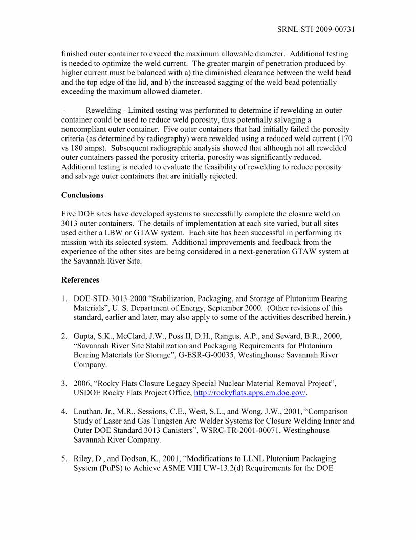
- Arc length controller– Occasional loss-of-arc upsets to the GTAW process were observed during the outer container welding campaigns. These upsets were typically arcinitiation failure, arc loss, or stub-out (contact between the electrode and weld pool). A portion of these upsets were attributed to variations in the gap between the outer container surface and the electrode. An “arc length controller” (Figure 3) was developed to provide a more consistent arc gap by providing a constant standoff from the weld joint surface. The arc length controller includes a spring-loaded compliance mechanism with a standoff guide that allows the electrode to follow the outer container contour and maintain a consistent arc gap throughout its orbit, regardless of variations in can-to-weld-head alignment.
Limited testing of the arc length controller mechanism indicates that it reduces failures relating to arc initiation, arc loss and stub-outs. Maintaining a consistent arc gap may also be expected to result in a more uniform weld profile, though this attribute has not been evaluated yet. The validity of the arc length controller design has been demonstrated, but additional work is needed to make it more robust for a production environment.
- Vented lid - Most of the outer containers that were welded during development of the arc length controller utilized the LANL vented lid design. No defects from internal pressure occurred during this period. Although the number of containers welded during these tests was insufficient for meaningful comparison with the occurrence of such defects in production, plans are to adopt the vented lid for future campaigns to eliminate the need to closely control the helium pressure prior to pressing the lid into place.
- Increased current - Limited testing was performed to investigate the impact of increased weld current on the outer container weld profile, especially with respect to penetration. As expected, the containers welded at higher current levels exhibited greater average penetration and greater penetration at the minima locations.
However, higher current also generated a wider weld bead, the edge of whichincreasingly approached the top edge of the lid as current was increased. Since the outer container weld is performed in the 2G position at SRS, increased weld current can increase the “sag” of the weld bead. Excessive sagging of the weld bead can cause the
SRNL-STI-2009-00731
finished outer container to exceed the maximum allowable diameter. Additional testing is needed to optimize the weld current. The greater margin of penetration produced by higher current must be balanced with a) the diminished clearance between the weld bead and the top edge of the lid, and b) the increased sagging of the weld bead potentially exceeding the maximum allowed diameter.
- Rewelding - Limited testing was performed to determine if rewelding an outer container could be used to reduce weld porosity, thus potentially salvaging a noncompliant outer container. Five outer containers that had initially failed the porosity criteria (as determined by radiography) were rewelded using a reduced weld current (170vs 180 amps). Subsequent radiographic analysis showed that although not all rewelded outer containers passed the porosity criteria, porosity was significantly reduced. Additional testing is needed to evaluate the feasibility of rewelding to reduce porosity and salvage outer containers that are initially rejected.
Conclusions
Five DOE sites have developed systems to successfully complete the closure weld on 3013 outer containers. The details of implementation at each site varied, but all sites used either a LBW or GTAW system. Each site has been successful in performing its mission with its selected system. Additional improvements and feedback from the experience of the other sites are being considered in a next-generation GTAW system at the Savannah River Site.
References
1. DOE-STD-3013-2000 “Stabilization, Packaging, and Storage of Plutonium Bearing Materials”, U. S. Department of Energy, September 2000. (Other revisions of this standard, earlier and later, may also apply to some of the activities described herein.)
2. Gupta, S.K., McClard, J.W., Poss II, D.H., Rangus, A.P., and Seward, B.R., 2000, “Savannah River Site Stabilization and Packaging Requirements for Plutonium Bearing Materials for Storage”, G-ESR-G-00035, Westinghouse Savannah River Company.
3. 2006, “Rocky Flats Closure Legacy Special Nuclear Material Removal Project”, USDOE Rocky Flats Project Office, http://rockyflats.apps.em.doe.gov/.
4. Louthan, Jr., M.R., Sessions, C.E., West, S.L., and Wong, J.W., 2001, “Comparison Study of Laser and Gas Tungsten Arc Welder Systems for Closure Welding Inner and Outer DOE Standard 3013 Canisters”, WSRC-TR-2001-00071, Westinghouse Savannah River Company.
5. Riley, D., and Dodson, K., 2001, “Modifications to LLNL Plutonium Packaging System (PuPS) to Achieve ASME VIII UW-13.2(d) Requirements for the DOE

SRNL-STI-2009-00731
Standard 3013-00 Outer Can Welder”, UCRL-ID-142335, Rev. 1, Lawrence Livermore National Laboratory.
6. Cannell, G., Daugherty, W., Gaston, L., Howard, S., Korinko, P., Maxwell, D., McKinney, G., Sessions, C., and West, S., 2003, “GTA Welding Research and Development for Plutonium Containment”, Proceedings of the 6th International Trends in Welding Research Conference, 15-19 April 2002, Pine Mountain, Ga, ASM International.
7. Cannell, G.R., Daugherty, W.L., and Stokes, M.W., 2002, “Welds Safeguard Plutonium-Bearing Containers”, Welding Journal, 81, No 7, 42-46.
8. Korinko, P.S., and Malene, S.H., 2001, “Considerations for the Weldability of Types 304L and 316L Stainless Steels”, Practical Failure Analysis, 1, Issue 4, 61-68.

SRNL-STI-2009-00731
Figure 2. Chill block sketch and details
Material: C15715 (Dispersion Strengthened Copper Alloy)Surface Finish: 63 RMSForce at Chill Block/Lid Interface: 2002 N (450 Pounds)
Figure 1. Sketch of 3013 outer container (left) and photo of container after welding
125 mm
254 mm
1. Outer Container Material (shell): SA312 Grade TP316/316L Seamless Pipe2. Lid Material (and bottom head): SA182 Grade F316/316L Bar3. Wall Thickness at Closure Weld = 3 mm

SRNL-STI-2009-00731
Figure 3. Arc length controller installed in the SRS GTAW weld head
Electrode
Stand-off guide