this document is downloaded from the digital open … · sound insulation of a double wall in...
TRANSCRIPT
This document is downloaded from theDigital Open Access Repository of VTT
VTThttp://www.vtt.fiP.O. box 1000FI-02044 VTTFinland
By using VTT Digital Open Access Repository you arebound by the following Terms & Conditions.
I have read and I understand the following statement:
This document is protected by copyright and otherintellectual property rights, and duplication or sale of all orpart of any of this document is not permitted, exceptduplication for research use or educational purposes inelectronic or print form. You must obtain permission forany other use. Electronic or print copies may not beoffered for sale.
Title NOVI - Advanced functional solutionsfor Noise and Vibration reduction ofmachinery, Deliverable D1.1 Physicalmechanisms of absorption and soundinsulation
Author(s) Uosukainen, SeppoCitation VTT (2014), 45 p.Date 2014Rights This report may be downloaded for
personal use only.
NOVI - Advanced functional solutions forNoise and Vibration reduction of machinery
D1.1 Physical mechanisms of absorption and soundinsulation, VTT
Author: Seppo UosukainenConfidentiality: Public
216.01.2012
SummaryProject name Project number/Short nameNOVI SP1 71902 – 1.1.2Author(s) PagesSeppo Uosukainen 45Keywords
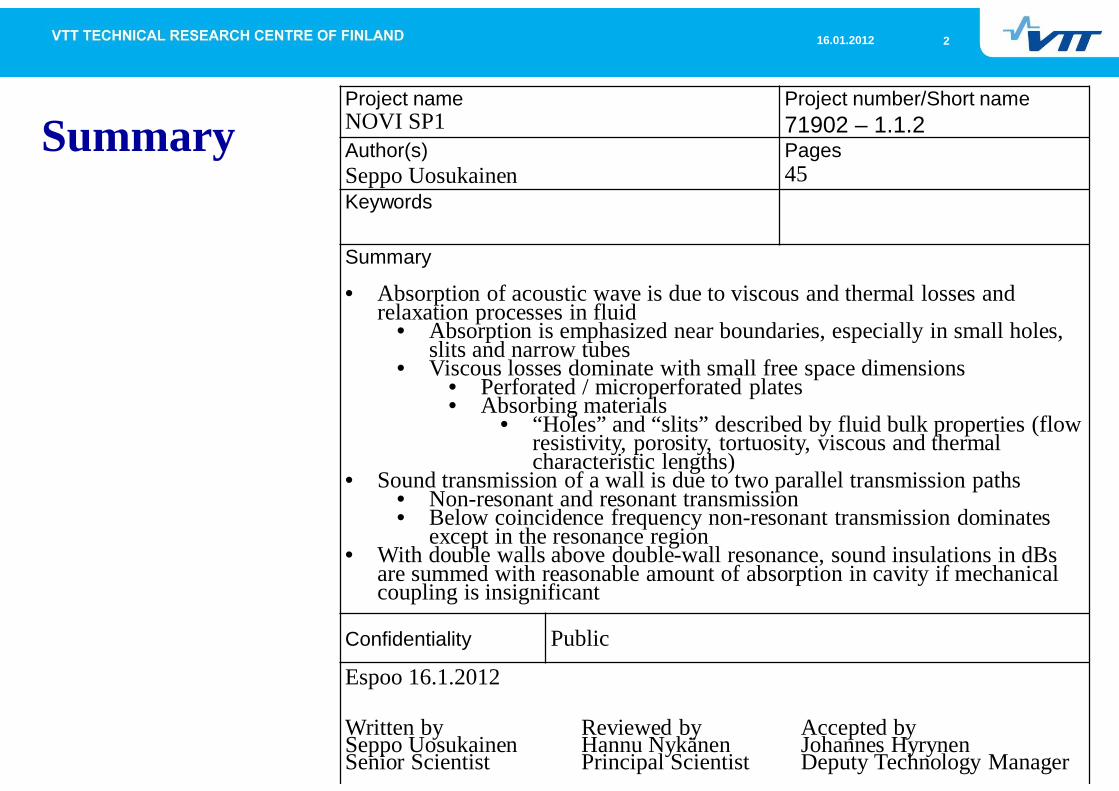
Summary
• Absorption of acoustic wave is due to viscous and thermal losses andrelaxation processes in fluid
• Absorption is emphasized near boundaries, especially in small holes,slits and narrow tubes
• Viscous losses dominate with small free space dimensions• Perforated / microperforated plates• Absorbing materials
• “Holes” and “slits” described by fluid bulk properties (flowresistivity, porosity, tortuosity, viscous and thermalcharacteristic lengths)
• Sound transmission of a wall is due to two parallel transmission paths• Non-resonant and resonant transmission• Below coincidence frequency non-resonant transmission dominates
except in the resonance region• With double walls above double-wall resonance, sound insulations in dBs
are summed with reasonable amount of absorption in cavity if mechanicalcoupling is insignificant
Confidentiality Public
Espoo 16.1.2012
Written bySeppo UosukainenSenior Scientist
Reviewed byHannu NykänenPrincipal Scientist
Accepted byJohannes HyrynenDeputy Technology Manager
316.01.2012
Table of content
Physical mechanisms of sound absorptionBasic conceptsLosses in mediumLosses at boundariesLosses in narrow tubes and in small holes and slits
Physical mechanisms of sound insulationBasic conceptsSound insulation of a single wall in diffuse fieldSound insulation of a double wall in diffuse fieldSound insulation of sandwich structures
416.01.2012
Table of content
Physical mechanisms of sound absorptionBasic concepts
516.01.2012
Basic concepts
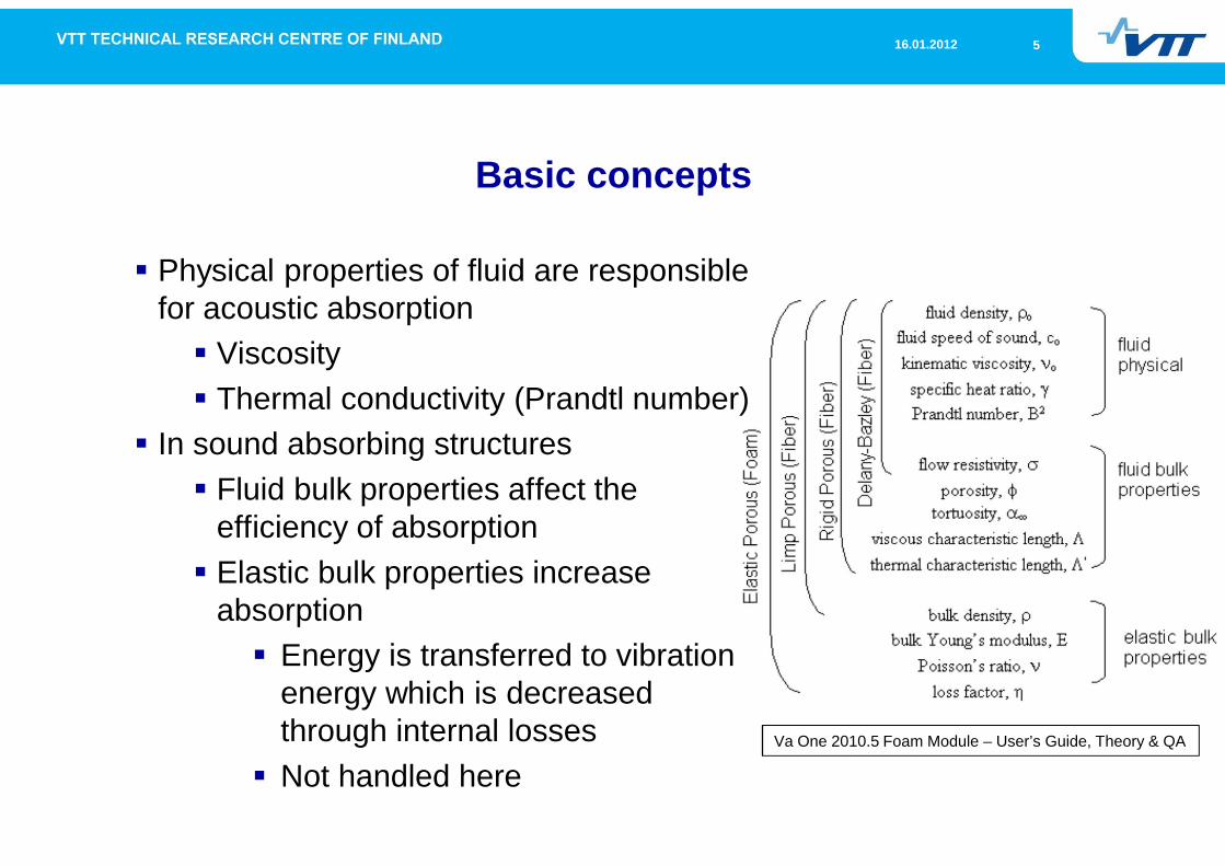
Physical properties of fluid are responsiblefor acoustic absorption
ViscosityThermal conductivity (Prandtl number)
In sound absorbing structuresFluid bulk properties affect theefficiency of absorptionElastic bulk properties increaseabsorption
Energy is transferred to vibrationenergy which is decreasedthrough internal lossesNot handled here
Va One 2010.5 Foam Module – User’s Guide, Theory & QA
616.01.2012
Fluid bulk properties
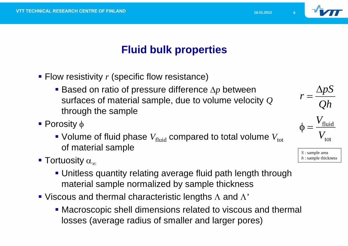
Flow resistivity r (specific flow resistance)Based on ratio of pressure difference p betweensurfaces of material sample, due to volume velocity Qthrough the sample
PorosityVolume of fluid phase Vfluid compared to total volume Vtotof material sample
TortuosityUnitless quantity relating average fluid path length throughmaterial sample normalized by sample thickness
Viscous and thermal characteristic lengths and ’Macroscopic shell dimensions related to viscous and thermallosses (average radius of smaller and larger pores)
tot
fluid
VVQhpSr
S : sample areah : sample thickness
716.01.2012
Absorption coefficient
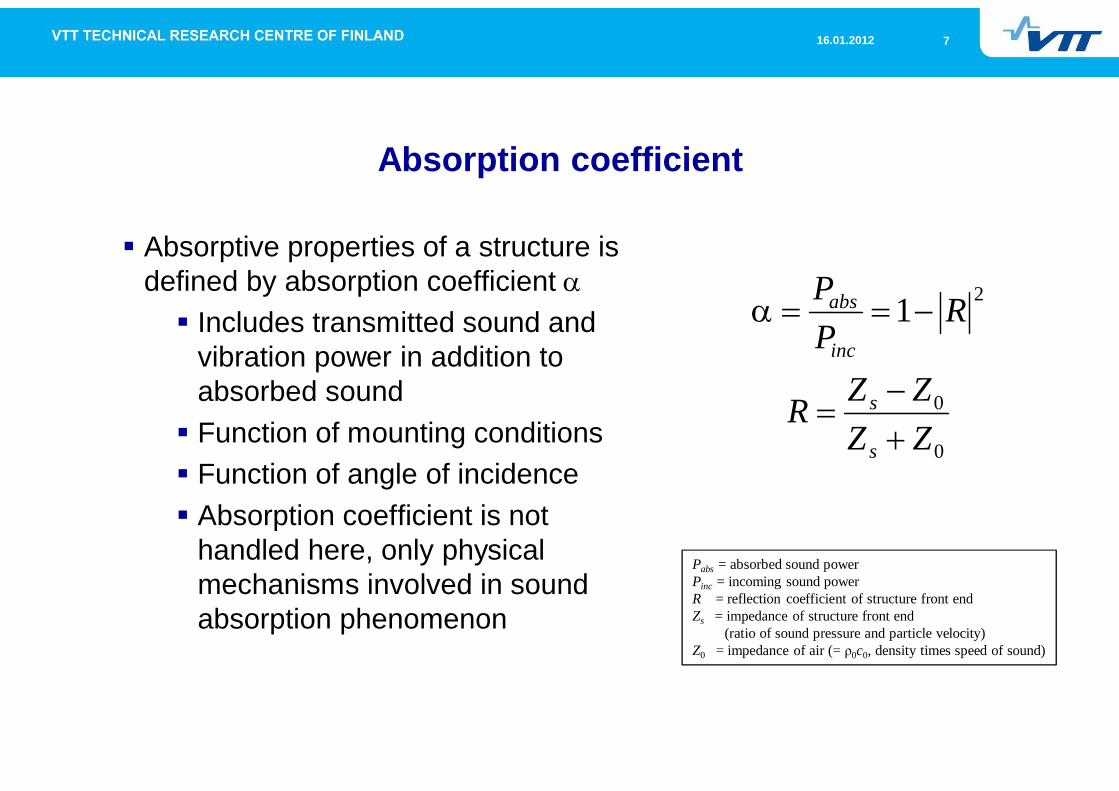
Absorptive properties of a structure isdefined by absorption coefficient
Includes transmitted sound andvibration power in addition toabsorbed soundFunction of mounting conditionsFunction of angle of incidenceAbsorption coefficient is nothandled here, only physicalmechanisms involved in soundabsorption phenomenon
0
0
21
ZZZZR
RPP
s
s
inc
abs
Pabs = absorbed sound powerPinc = incoming sound powerR = reflection coefficient of structure front endZs = impedance of structure front end
(ratio of sound pressure and particle velocity)Z0 = impedance of air (= 0c0, density times speed of sound)
816.01.2012
Table of content
Physical mechanisms of sound absorption
Losses in medium
916.01.2012
Losses in medium (1)
PhenomenaViscous losses
Involved in strain of fluid elements caused by particlevelocity of sound wave
Thermal lossesInvolved in thermal conduction from sound pressuremaxima to sound pressure minima in sound wave
RelaxationVibration state of molecules is excited due to sound waveExcited state is relaxed after a while
1016.01.2012
Losses in medium (2)
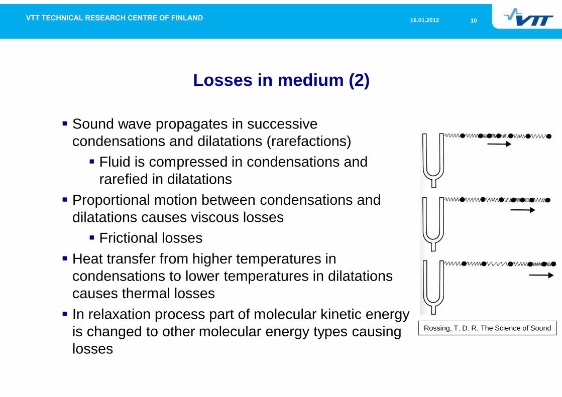
Sound wave propagates in successivecondensations and dilatations (rarefactions)
Fluid is compressed in condensations andrarefied in dilatations
Proportional motion between condensations anddilatations causes viscous losses
Frictional lossesHeat transfer from higher temperatures incondensations to lower temperatures in dilatationscauses thermal lossesIn relaxation process part of molecular kinetic energyis changed to other molecular energy types causinglosses
Rossing, T. D. R. The Science of Sound
1116.01.2012
Losses in medium (3)
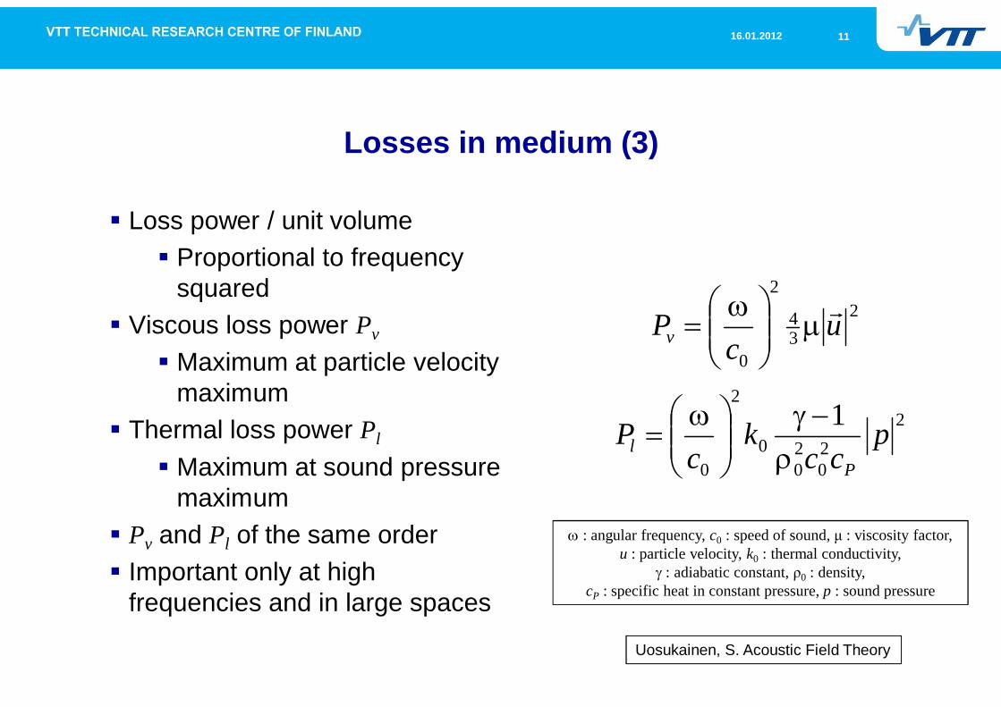
Loss power / unit volumeProportional to frequencysquared
Viscous loss power Pv
Maximum at particle velocitymaximum
Thermal loss power Pl
Maximum at sound pressuremaximum
Pv and Pl of the same orderImportant only at highfrequencies and in large spaces
234
2
0
uc
Pv
220
20
0
2
0
1 pcc
kc
PP
l
: angular frequency, c0 : speed of sound, : viscosity factor,u : particle velocity, k0 : thermal conductivity,
: adiabatic constant, 0 : density,cP : specific heat in constant pressure, p : sound pressure
Uosukainen, S. Acoustic Field Theory
1216.01.2012
Table of content
Physical mechanisms of sound absorption
Losses at boundaries
1316.01.2012
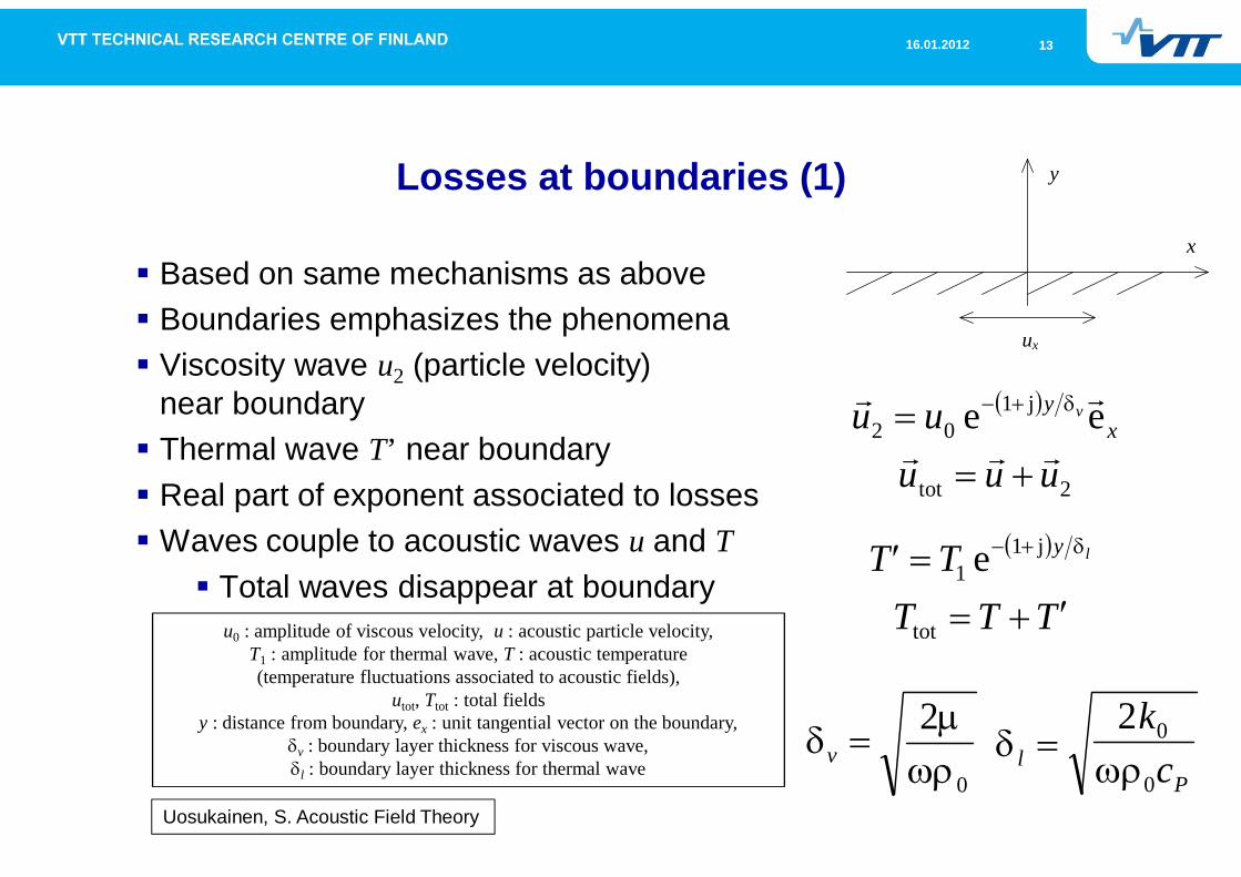
Losses at boundaries (1)
Based on same mechanisms as aboveBoundaries emphasizes the phenomenaViscosity wave u2 (particle velocity)near boundaryThermal wave T’ near boundaryReal part of exponent associated to lossesWaves couple to acoustic waves u and T
Total waves disappear at boundary
2tot
j102 ee
uuuuu x
y v
0
2v
TTTTT ly
tot
j11 e
lP
kc
2 0
0
u0 : amplitude of viscous velocity, u : acoustic particle velocity,T1 : amplitude for thermal wave, T : acoustic temperature(temperature fluctuations associated to acoustic fields),
utot, Ttot : total fieldsy : distance from boundary, ex : unit tangential vector on the boundary,
v : boundary layer thickness for viscous wave,l : boundary layer thickness for thermal wave
Uosukainen, S. Acoustic Field Theory
y
x
ux
1416.01.2012
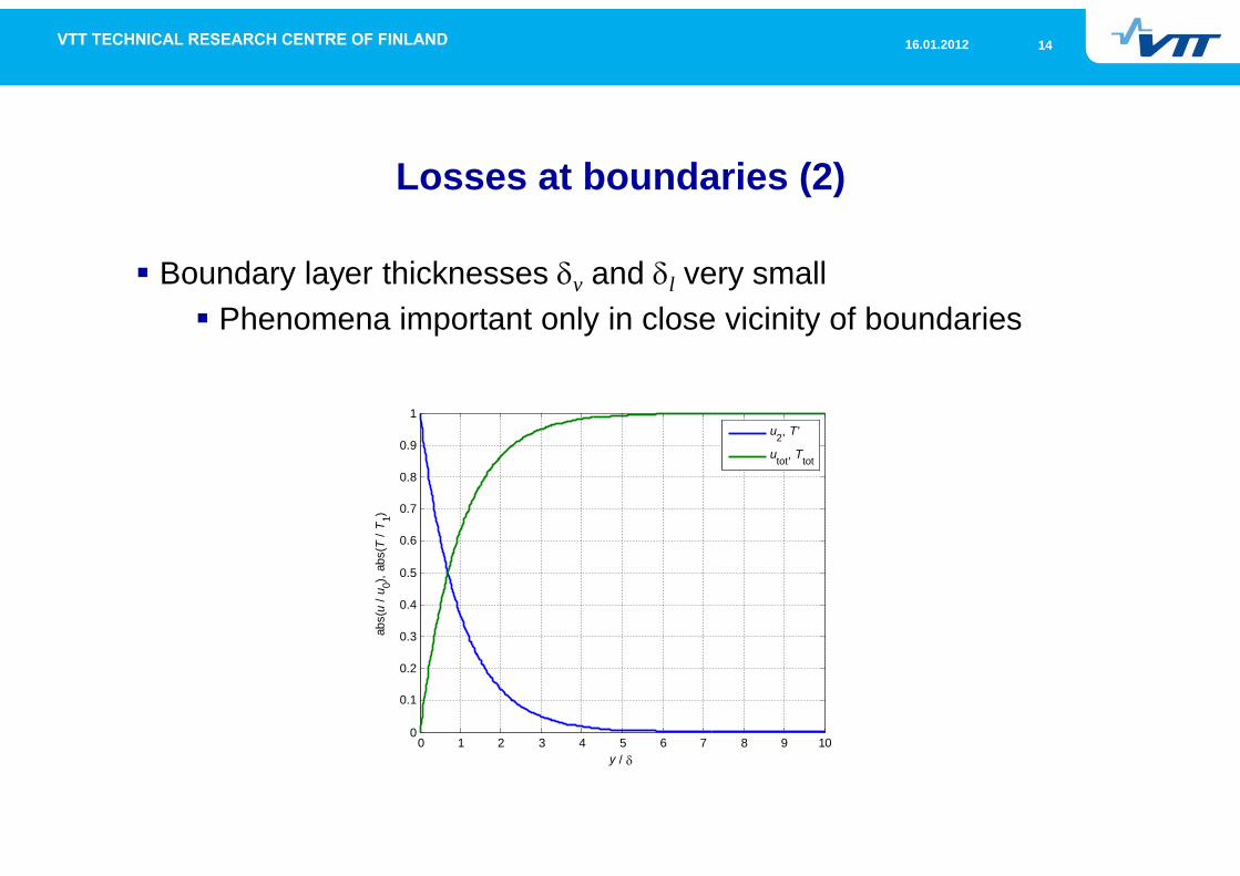
Losses at boundaries (2)
Boundary layer thicknesses v and l very smallPhenomena important only in close vicinity of boundaries
0 1 2 3 4 5 6 7 8 9 100
0.1
0.2
0.3
0.4
0.5
0.6
0.7
0.8
0.9
1
y /
abs(
u/u
0),ab
s(T
/T1)
u2, T'
utot, Ttot
1516.01.2012
Table of content
Physical mechanisms of sound absorption
Losses in narrow tubes and in small holes and slits
1616.01.2012
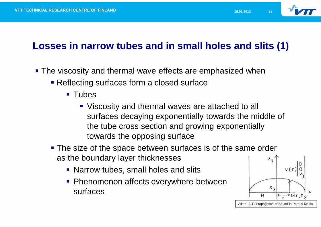
Losses in narrow tubes and in small holes and slits (1)
The viscosity and thermal wave effects are emphasized whenReflecting surfaces form a closed surface
TubesViscosity and thermal waves are attached to allsurfaces decaying exponentially towards the middle ofthe tube cross section and growing exponentiallytowards the opposing surface
The size of the space between surfaces is of the same orderas the boundary layer thicknesses
Narrow tubes, small holes and slitsPhenomenon affects everywhere betweensurfaces
Allard, J. F. Propagation of Sound in Porous Media
1716.01.2012
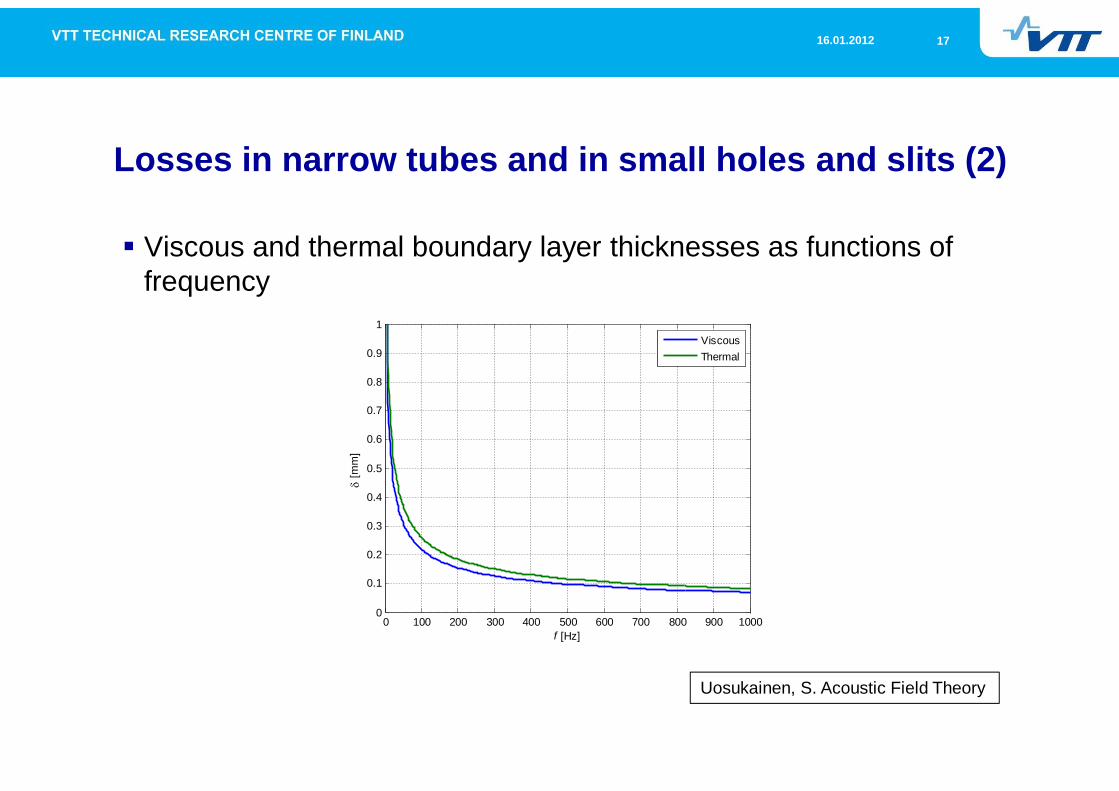
Losses in narrow tubes and in small holes and slits (2)
Viscous and thermal boundary layer thicknesses as functions offrequency
Uosukainen, S. Acoustic Field Theory
0 100 200 300 400 500 600 700 800 900 10000
0.1
0.2
0.3
0.4
0.5
0.6
0.7
0.8
0.9
1
f [Hz]
[mm
]ViscousThermal
1816.01.2012
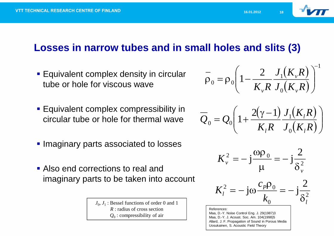
Losses in narrow tubes and in small holes and slits (3)
Equivalent complex density in circulartube or hole for viscous wave
Equivalent complex compressibility incircular tube or hole for thermal wave
Imaginary parts associated to losses
Also end corrections to real andimaginary parts to be taken into account
1
0
100
21RKJRKJ
RK v
v
v
202 2jj
vvK
RKJRKJ
RKQQ
l
l
l 0
100
121
20
02 2jjl
Pl k
cKJ0, J1 : Bessel functions of order 0 and 1
R : radius of cross sectionQ0 : compressibility of air
References:Maa, D.-Y. Noise Control Eng. J. 29(1987)3Maa, D.-Y. J. Acoust. Soc. Am. 104(1998)5Allard, J. F. Propagation of Sound in Porous MediaUosukainen, S. Acoustic Field Theory
1916.01.2012
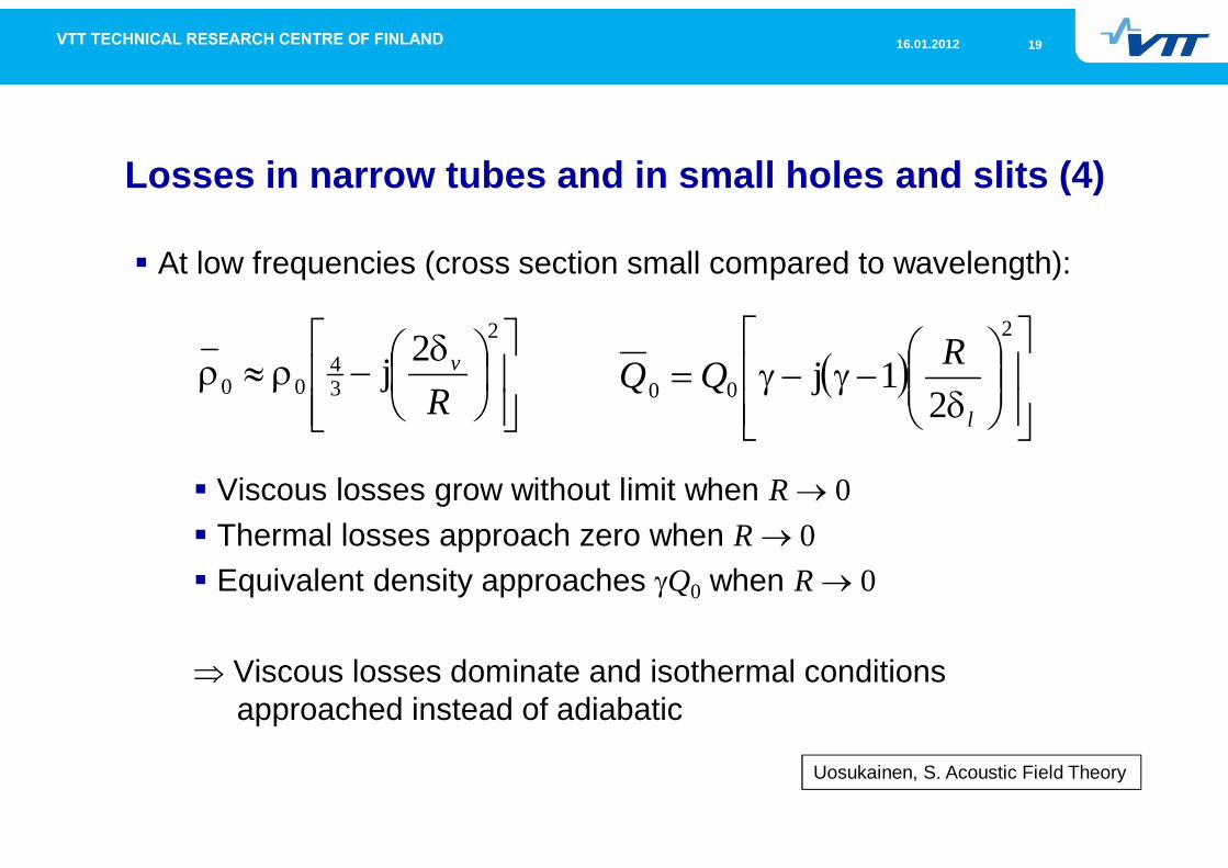
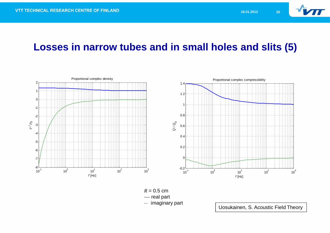
Losses in narrow tubes and in small holes and slits (4)
At low frequencies (cross section small compared to wavelength):
Viscous losses grow without limit when R 0Thermal losses approach zero when R 0Equivalent density approaches Q0 when R 0
Viscous losses dominate and isothermal conditionsapproached instead of adiabatic
2
34
002jR
v2
00 21j
l
RQQ
Uosukainen, S. Acoustic Field Theory
2016.01.2012
Losses in narrow tubes and in small holes and slits (5)
R = 0.5 cmreal partimaginary part
Uosukainen, S. Acoustic Field Theory
10-1
100
101
102
103
-0.2
0
0.2
0.4
0.6
0.8
1
1.2
1.4
Q/Q
0
Proportional complex compressibility
f [Hz]10
-110
010
110
210
3-8
-7
-6
-5
-4
-3
-2
-1
0
1
2
f [Hz]
/0
Proportional complex density
2116.01.2012
Losses in narrow tubes and in small holes and slits (6)
Applications of above:Perforated / microperforated platesAbsorbing materials
Most important loss mechanism”Holes” and ”slits” described by fluid bulk properties
Flow resistivity most importantPorosity, tortuosity, viscous and thermalcharacteristic lengths
Irreversible effects in the skeleton affect also
Viscosity of air is the most important phenomenon causingacoustic losses in (micro)perforated plates and absorbing materials
2216.01.2012
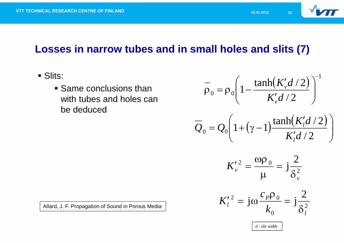
Losses in narrow tubes and in small holes and slits (7)
Slits:Same conclusions thanwith tubes and holes canbe deduced
1
00 2/2/tanh1
dKdK
v
v
2/2/tanh1100 dK
dKQQl
l
202 2j
vvK
20
02 2jjl
Pl k
cKAllard, J. F. Propagation of Sound in Porous Media
d : slit width
2316.01.2012
Table of content
Physical mechanisms of sound insulationBasic concepts
2416.01.2012
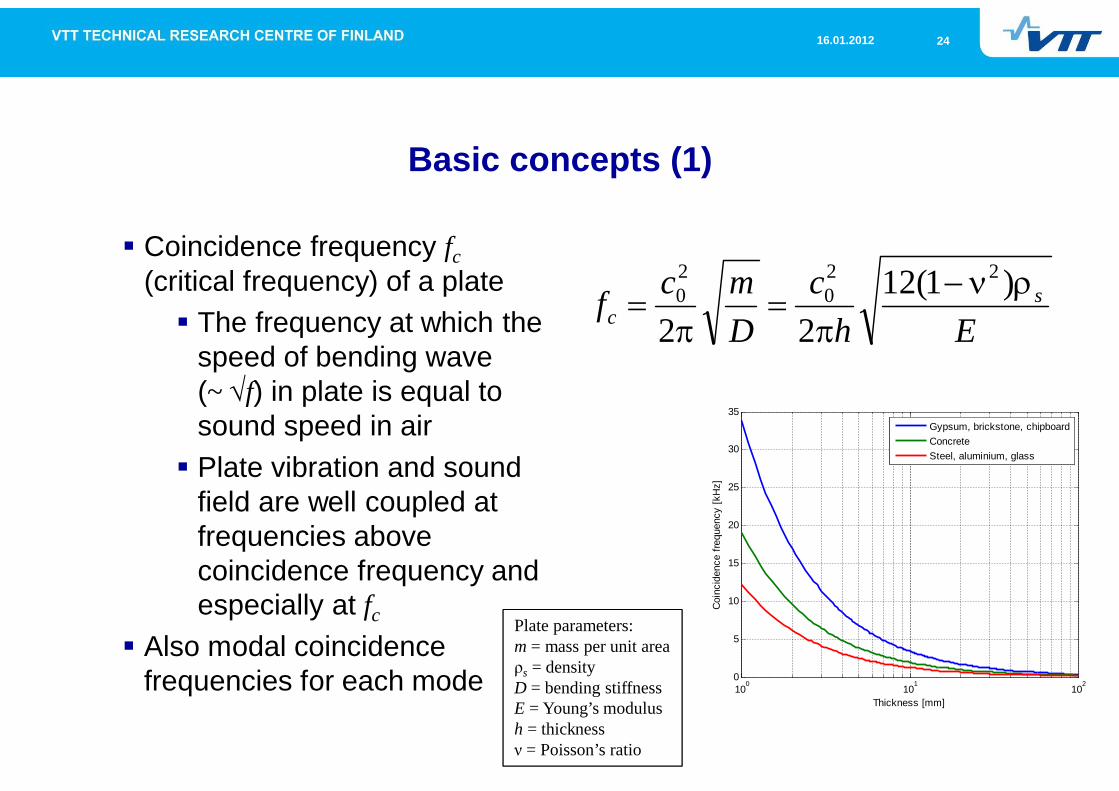
Basic concepts (1)
Coincidence frequency fc(critical frequency) of a plate
The frequency at which thespeed of bending wave(~ f) in plate is equal tosound speed in airPlate vibration and soundfield are well coupled atfrequencies abovecoincidence frequency andespecially at fc
Also modal coincidencefrequencies for each mode
Ehc
Dmcf s
c)1(12
22
220
20
Plate parameters:m = mass per unit area
s = densityD = bending stiffnessE = Young’s modulush = thickness = Poisson’s ratio
100 101 1020
5
10
15
20
25
30
35
Coin
cide
nce
frequ
ency
[kH
z]Thickness [mm]
Gypsum, brickstone, chipboardConcreteSteel, aluminium, glass
2516.01.2012
Basic concepts (2)
Radiation ratio of vibrationMeasure of proportional radiation efficiencyDepends on vibration types
Proportions of resonant and non-resonant vibration
Depends on excitation(mechanical / acoustical)
200 vScP
Plate parameters:P = radiated sound powerS = areav = vibration velocity< > = mean value
2616.01.2012
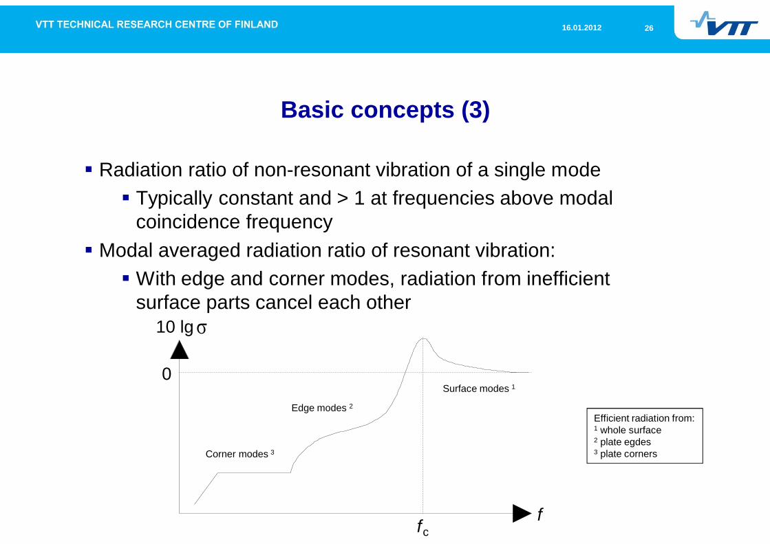
Basic concepts (3)
Radiation ratio of non-resonant vibration of a single modeTypically constant and > 1 at frequencies above modalcoincidence frequency
Modal averaged radiation ratio of resonant vibration:With edge and corner modes, radiation from inefficientsurface parts cancel each other
10 lg
fc
0
f
Surface modes 1
Edge modes 2
Corner modes 3
Efficient radiation from:1 whole surface2 plate egdes3 plate corners
2716.01.2012
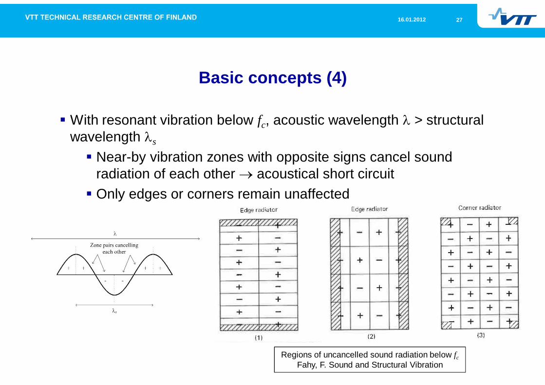
Basic concepts (4)
With resonant vibration below fc, acoustic wavelength > structuralwavelength s
Near-by vibration zones with opposite signs cancel soundradiation of each other acoustical short circuitOnly edges or corners remain unaffected
Regions of uncancelled sound radiation below fcFahy, F. Sound and Structural Vibration
2816.01.2012
Basic concepts (5)
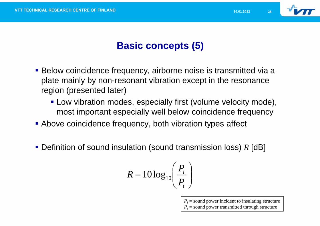
Below coincidence frequency, airborne noise is transmitted via aplate mainly by non-resonant vibration except in the resonanceregion (presented later)
Low vibration modes, especially first (volume velocity mode),most important especially well below coincidence frequency
Above coincidence frequency, both vibration types affect
Definition of sound insulation (sound transmission loss) R [dB]
t
i
PPR 10log10
Pi = sound power incident to insulating structurePt = sound power transmitted through structure
2916.01.2012
Table of content
Physical mechanisms of sound insulation
Sound insulation of a single wall in diffuse field
3016.01.2012
Sound insulation of a single wall in diffuse field (1)
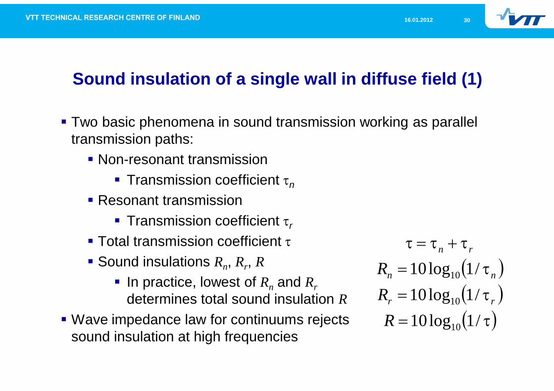
Two basic phenomena in sound transmission working as paralleltransmission paths:
Non-resonant transmissionTransmission coefficient n
Resonant transmissionTransmission coefficient r
Total transmission coefficientSound insulations Rn, Rr, R
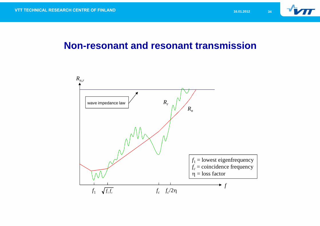
In practice, lowest of Rn and Rrdetermines total sound insulation R
Wave impedance law for continuums rejectssound insulation at high frequencies
/1log10/1log10/1log10
10
10
10
RRR
rr
nn
rn
3116.01.2012
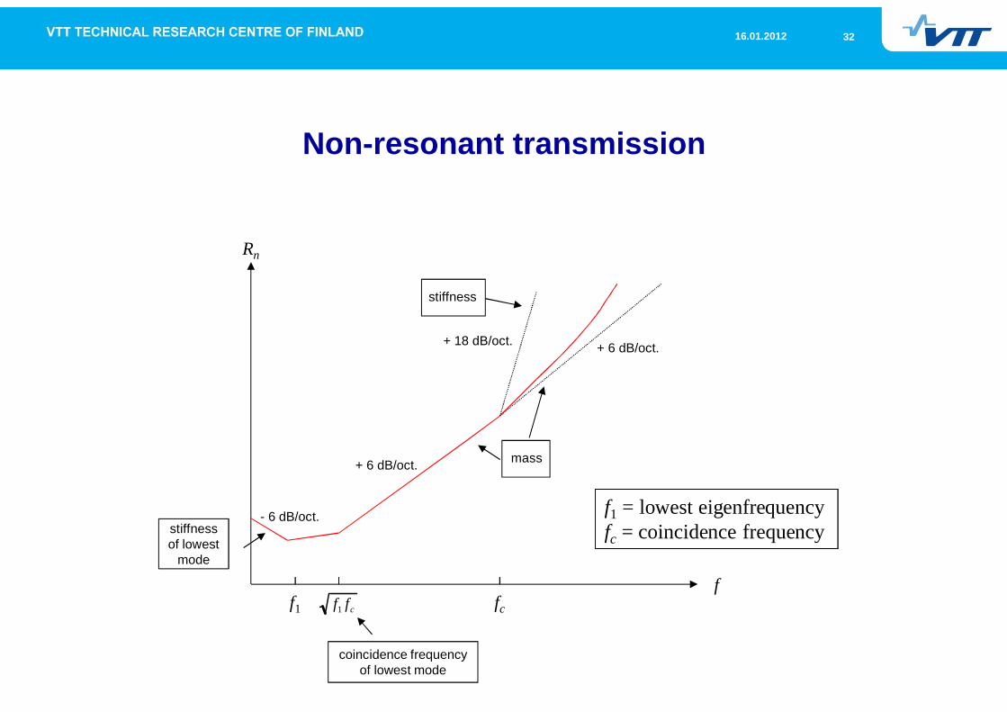
Sound insulation of a single wall in diffuse field (2)
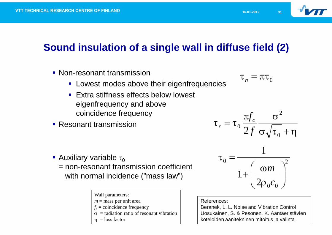
Non-resonant transmissionLowest modes above their eigenfrequenciesExtra stiffness effects below lowesteigenfrequency and abovecoincidence frequency
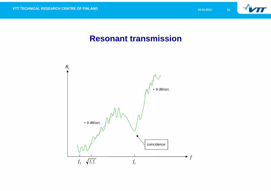
Resonant transmission
Auxiliary variable 0= non-resonant transmission coefficient
with normal incidence (”mass law”)
2
00
0
21
1
cm
0n
0
2
0 2 ffc
r
Wall parameters:m = mass per unit areafc = coincidence frequency
= radiation ratio of resonant vibration= loss factor
References:Beranek, L. L. Noise and Vibration ControlUosukainen, S. & Pesonen, K. Ääntäeristävienkoteloiden äänitekninen mitoitus ja valinta
3216.01.2012
Non-resonant transmission
Rn
f
- 6 dB/oct.
+ 6 dB/oct.
+ 18 dB/oct. + 6 dB/oct.
stiffnessof lowest
mode
mass
stiffness
f1 = lowest eigenfrequencyfc = coincidence frequency
f1 fccff1
coincidence frequencyof lowest mode
3316.01.2012
Resonant transmission
Rr
f
+ 9 dB/oct.
+ 9 dB/oct.
f1 fc
coincidence
cff1
3416.01.2012
Non-resonant and resonant transmission
Rn,r
ff1 fccff1 fc/2
wave impedance law
f1 = lowest eigenfrequencyfc = coincidence frequency
= loss factor
Rn
Rr
3516.01.2012
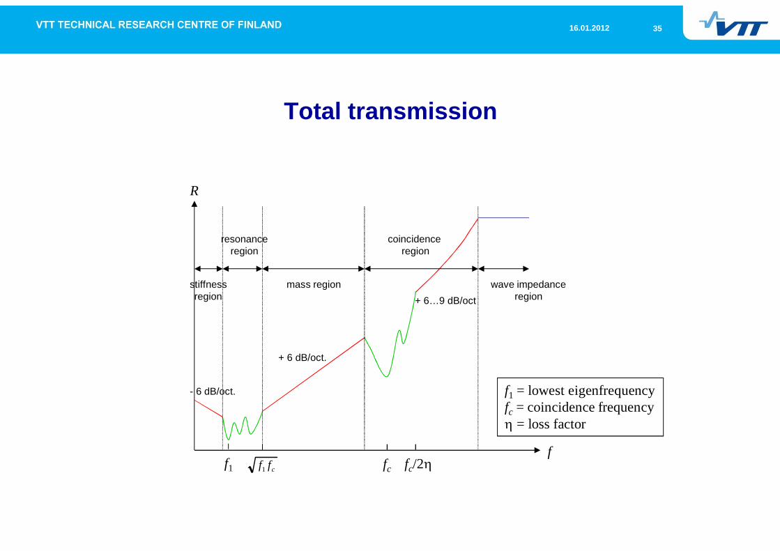
Total transmission
R
ff1 fccff1 fc/2
mass region
coincidenceregion
wave impedanceregion
resonanceregion
stiffnessregion
f1 = lowest eigenfrequencyfc = coincidence frequency
= loss factor
- 6 dB/oct.
+ 6 dB/oct.
+ 6…9 dB/oct
3616.01.2012
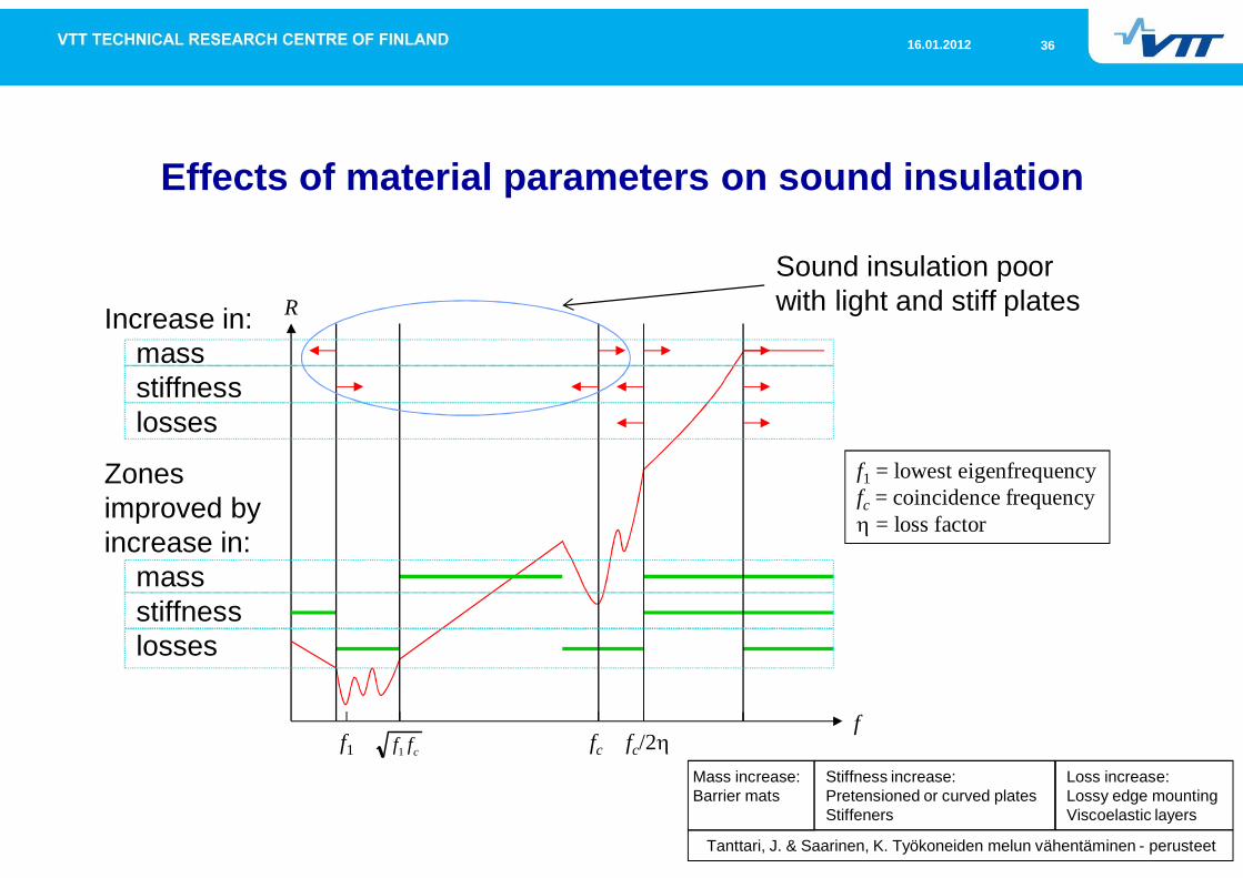
Effects of material parameters on sound insulation
R
ff1 fccff1 fc/2
Zonesimproved byincrease in:
massstiffnesslosses
Increase in:massstiffnesslosses
f1 = lowest eigenfrequencyfc = coincidence frequency
= loss factor
Loss increase:Lossy edge mountingViscoelastic layers
Tanttari, J. & Saarinen, K. Työkoneiden melun vähentäminen - perusteet
Sound insulation poorwith light and stiff plates
Stiffness increase:Pretensioned or curved platesStiffeners
Mass increase:Barrier mats
3716.01.2012
Table of content
Physical mechanisms of sound insulation
Sound insulation of a double wall in diffuse field
3816.01.2012
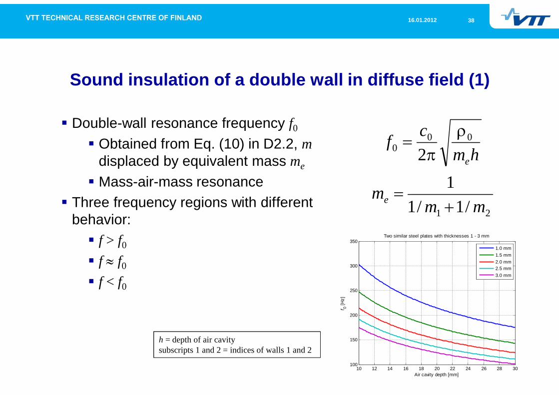
Sound insulation of a double wall in diffuse field (1)
Double-wall resonance frequency f0
Obtained from Eq. (10) in D2.2, mdisplaced by equivalent mass me
Mass-air-mass resonanceThree frequency regions with differentbehavior:
f > f0
f f0
f < f0
21
000
/1/11
2
mmm
hmcf
e
e
h = depth of air cavitysubscripts 1 and 2 = indices of walls 1 and 2
10 12 14 16 18 20 22 24 26 28 30100
150
200
250
300
350
Air cavity depth [mm]
f 0[H
z]
Two similar steel plates with thicknesses 1 - 3 mm
1.0 mm1.5 mm2.0 mm2.5 mm3.0 mm
3916.01.2012
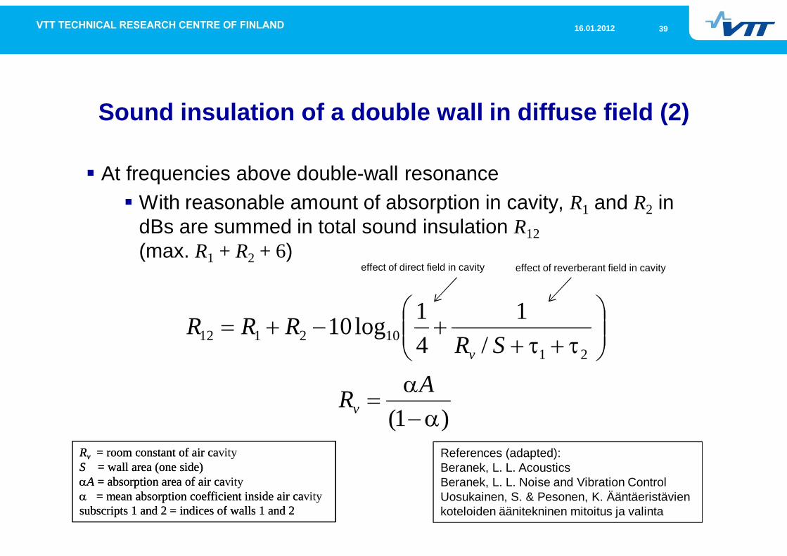
Sound insulation of a double wall in diffuse field (2)
At frequencies above double-wall resonanceWith reasonable amount of absorption in cavity, R1 and R2 indBs are summed in total sound insulation R12(max. R1 + R2 + 6)
)1(
/1
41log10
21102112
AR
SRRRR
v
v
Rv = room constant of air cavityS = wall area (one side)
A = absorption area of air cavity= mean absorption coefficient inside air cavity
subscripts 1 and 2 = indices of walls 1 and 2
References (adapted):Beranek, L. L. AcousticsBeranek, L. L. Noise and Vibration ControlUosukainen, S. & Pesonen, K. Ääntäeristävienkoteloiden äänitekninen mitoitus ja valinta
effect of direct field in cavity
Rv = room constant of air caS = wall area (one side)
A = absorption area of air ca= mean absorption coefficient inside air ca
subscripts 1 and 2 = indices of walls 1 and 2
effect of reverberant field in cavity
4016.01.2012
Sound insulation of a double wall in diffuse field (3)
At double-wall resonance frequencySound insulation is close to 0 dB without absorbents in cavityand with a small amount of mechanical damping
Increasing internal losses to double increases soundinsulation 6 dBUsing walls of different mass per unit area increasessound insulation
This degrades sound insulation at higher frequenciesAt frequencies below double-wall resonance
Sound insulation is as with a single wall, m replaced by totalmass m1 + m2
Fahy, F. & Gardonio, P. Sound and Structural Vibration
4116.01.2012
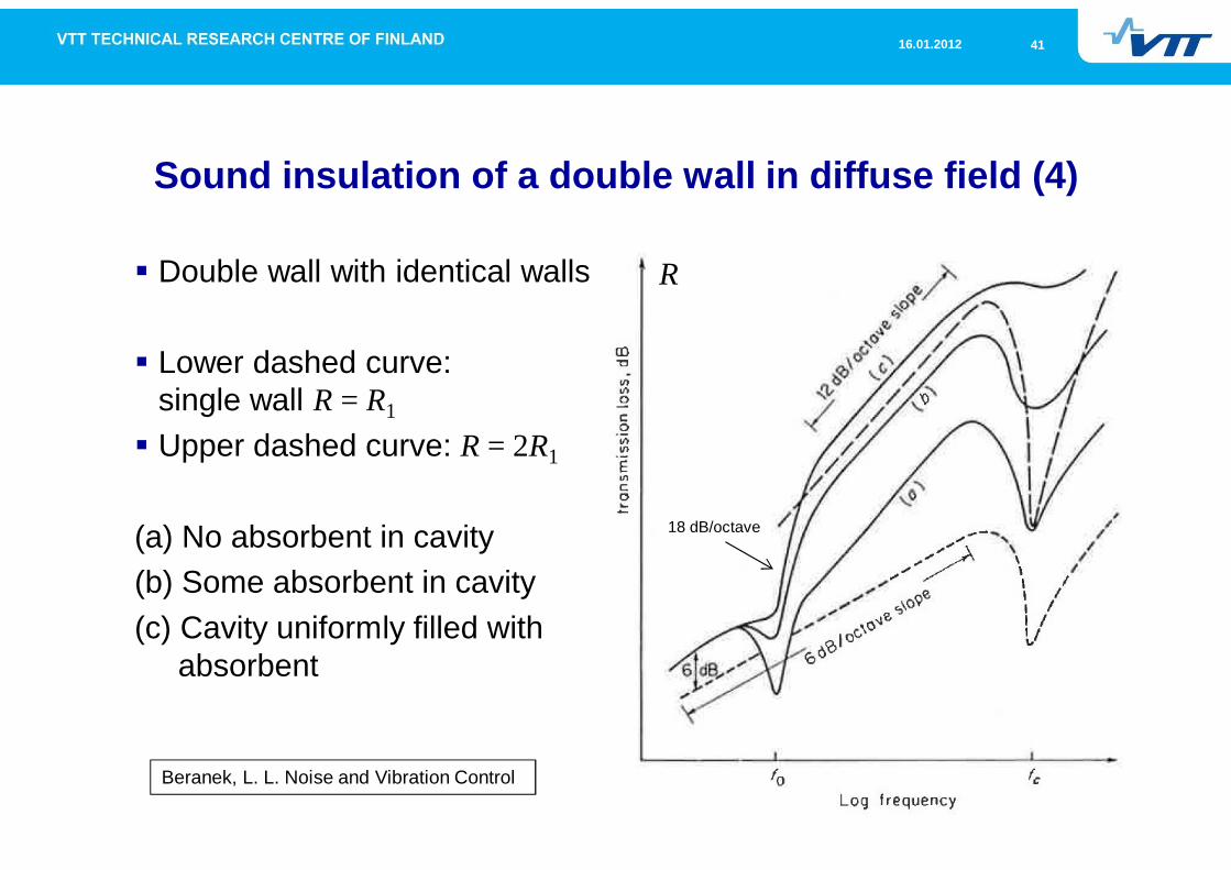
Sound insulation of a double wall in diffuse field (4)
Double wall with identical walls
Lower dashed curve:single wall R = R1
Upper dashed curve: R = 2R1
(a) No absorbent in cavity(b) Some absorbent in cavity(c) Cavity uniformly filled with
absorbent
Beranek, L. L. Noise and Vibration Control
18 dB/octave
R
4216.01.2012
Sound insulation of a double wall in diffuse field (5)
Mechanical coupling via supporting structures or absorbent incavity degrades sound insulation at whole frequency range,especially with resonant vibration
Double-wall resonance occurs at higher frequenciesCoupling decreases with resilient mounting
Effects of coincidence and lowest modes can be splitted in twofrequencies with lower dips using different walls
Sound insulation at high frequencies decreasesAir cavity resonances degrade sound insulation at high frequencies
Effects decrease with using absorbent in air cavityEffects of absorbent (increase of losses) are higher with deepercavities
Tanttari, J. & Saarinen, K. Työkoneiden melun vähentäminen - perusteet
4316.01.2012
Table of content
Physical mechanisms of sound insulation
Sound insulation of sandwich structures
4416.01.2012
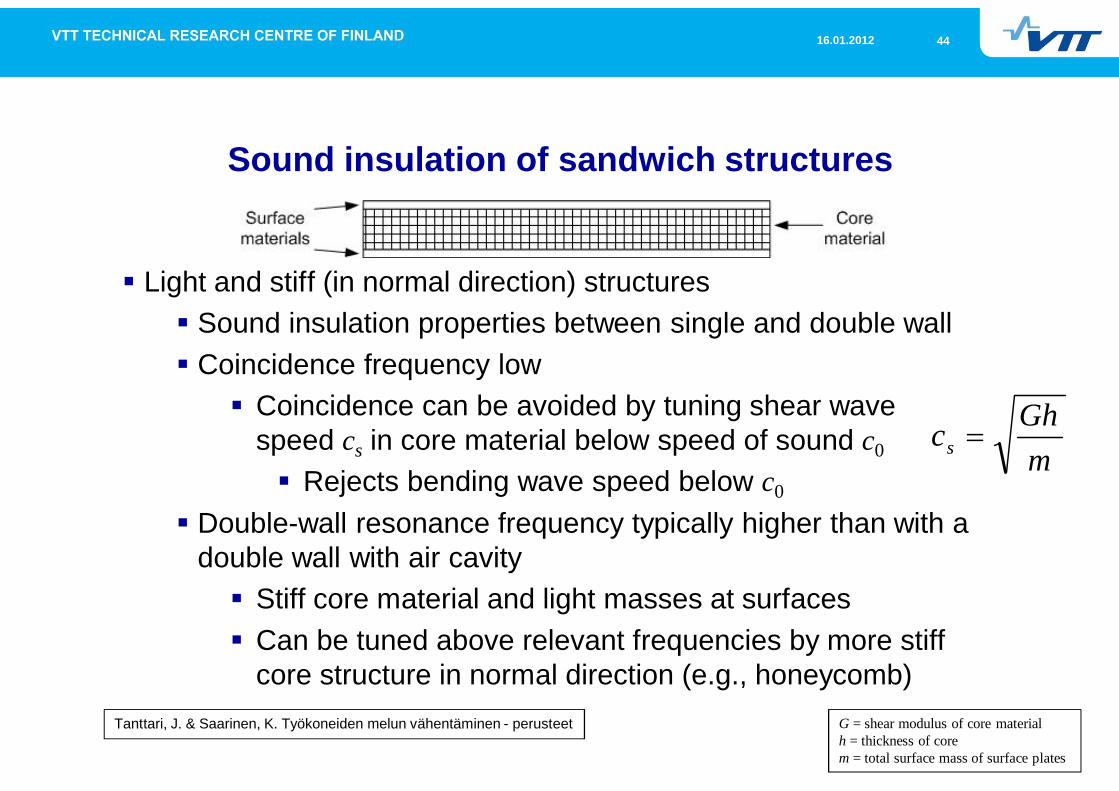
Sound insulation of sandwich structures
Light and stiff (in normal direction) structuresSound insulation properties between single and double wallCoincidence frequency low
Coincidence can be avoided by tuning shear wavespeed cs in core material below speed of sound c0
Rejects bending wave speed below c0
Double-wall resonance frequency typically higher than with adouble wall with air cavity
Stiff core material and light masses at surfacesCan be tuned above relevant frequencies by more stiffcore structure in normal direction (e.g., honeycomb)
mGhcs
G = shear modulus of core materialh = thickness of corem = total surface mass of surface plates
Tanttari, J. & Saarinen, K. Työkoneiden melun vähentäminen - perusteet

4516.01.2012
VTT creates business fromtechnology