this document downloaded from vulcanhammer › 2017 › 08 › tn-1362.pdf · security...
TRANSCRIPT

Terms and Conditions of Use:
this document downloaded from
vulcanhammer.infothe website about Vulcan Iron Works Inc. and the pile driving equipment it manufactured
All of the information, data and computer software (“information”) presented on this web site is for general information only. While every effort will be made to insure its accuracy, this information should not be used or relied on for any specific application without independent, competent professional examination and verification of its accuracy, suit-ability and applicability by a licensed professional. Anyone making use of this information does so at his or her own risk and assumes any and all liability resulting from such use. The entire risk as to quality or usability of the information contained within is with the reader. In no event will this web page or webmaster be held liable, nor does this web page or its webmaster provide insurance against liability, for any damages including lost profits, lost savings or any other incidental or consequential damages arising from the use
or inability to use the information contained within.
This site is not an official site of Prentice-Hall, Pile Buck, or Vulcan Foundation Equipment. All references to sources of software, equipment, parts, service or
repairs do not constitute an endorsement.
Visit our companion sitehttp://www.vulcanhammer.org
Technical Note N-1362
' EVALUATION OF HYDROACOUSTIC RAPID- IMPACTING PILE DRIVER . b Y
Career. J. Ward; Ph. D.
Sponsored by
NAVAL FACILITIES ENGINEERING COMMAND
(i." A
Approved for public release? distribution unlimited.
CIVIL ENGINEERING LABORATORY Naval Construction Battalion Center Port Hueneme, California 93043

Unclassified S E C U R I T Y C L A S S I F I C A T I O N O F T H I S P A G E ( W h e n Dora E n l e r e d l
4. T I T L E (and Subr i l le)
EVALUATION O F HYDROACOUSTIC RAPID- IMPACTING PILE DRIVER
REPORTDOCUMENTATION PAGE
Carter J. Ward, Ph.D.
1. R E P O R T N U M B E R
'I'N-1362
9 P E R F O R M I N G O R G A N I Z A T I O N N A M E A N D 4DDRESS
CIVIL ENGINEERING LABORATORY
2. G O V T ACCESSION N O
DN244024
Naval Construction Battalion Center Port Hueneme. California 93043
11. C O N T R O L L I N G O F F I C E N A M E A N 0 ADDRESS
Naval Facilities Engineering Command Alexandria, Virginia 22 3 3 2
14 M C N l T O R l N G AGENCY N A M E 8 ADDRESS01 dil leren! i r om Conlrl,llrn&? Ollcre!
Approved for public release; distribution unlimited
R E A D INSTRIJCTIONS E E F ~ R E ~ C O M P L E ~ ~ N C - F O R M
3 R E C I P I E N T ' S C A T A L O G N U M B E R
5 T Y P E O F R E P O R T 8 P E R I O D C O V E R E D
Final; 1 July 1971-30 Jun 197
6 P E R F O R M I N G ORG. R E P O R T N U M B E R
8 C O N T R A C T O R G R A N T N U M B E R ( \ )
10 P R O G R A M E L E M E N T P R O J E C T TASK A R E A & WORK U N I T N U M B E R S
62755N YF53.536.006.01.011
I 2 R E P O R T D A T E
November 1974 13 N U M B E R O F P A S E S
46 15 S E C U R I T Y C L A S S l o1 l h , s r e p o r l )
Unclassified
1 5 n O E C L A S S I F I C A T I O N DOWNGRAOING S C H E D U L E
17 OISTR1BUTION S T A T E M E N T l o 1 ,he a b s r r a r l r n l e r e d ~n B l a c k 20, $ 1 d l l l e ren r from R r p o r l )
18 S U P P L E M E N T A R Y N O T E S I 19 K E Y WORDS (Con,lnue on r e v e r s e ~ i d e 1 1 n e r c s r n r y end ,denr. ly bv b l o c k n u m b e r )
Hydroacoustic impact tool, hydroacoustic driver, hydroacoustic pile driver, pile driver, rapid-impacting pile driver.
20 A B S T R A C T (Conl,nue on r e v e r s e side I f n ecesrar ) . end ~ d e n t r l y bv b l o c k n u m b e r )
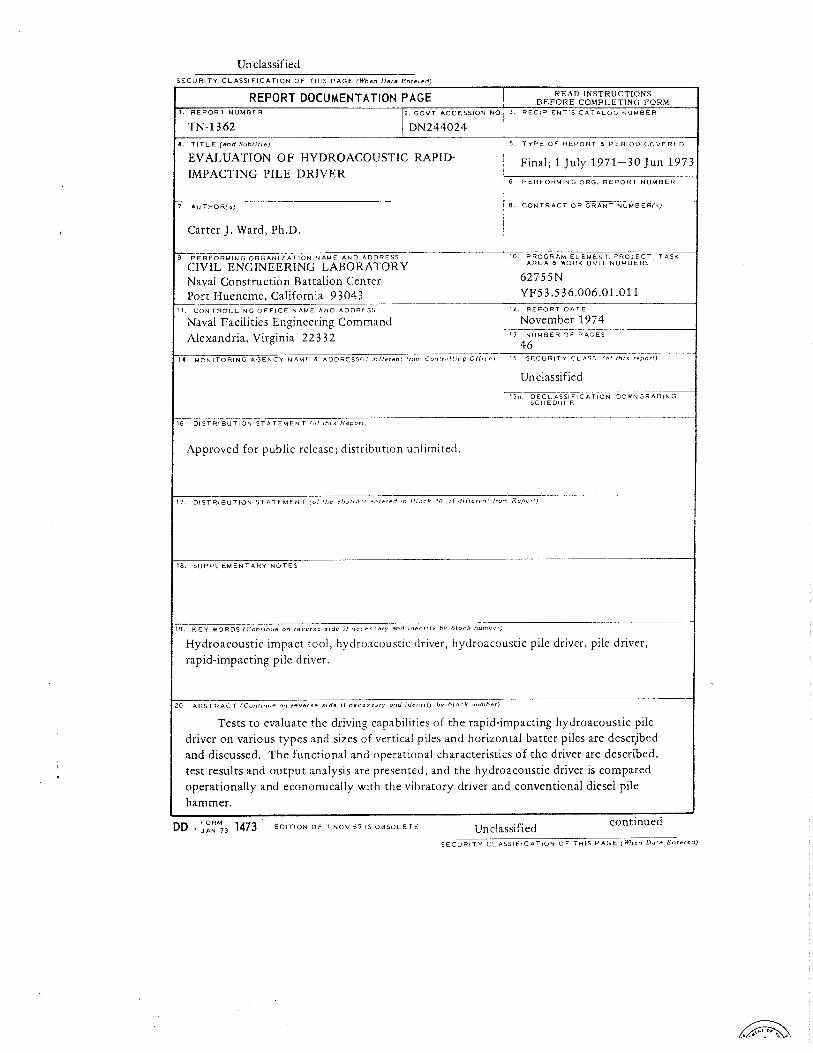
Tests t o evaluate the driving capabilities of the rapid-impacting hydroacoustic pile driver on various types and sizes of vertical piles and horizontal batter piles are descjbed and discussed. The functional and operational characteristics of the driver are described, test results and output analysis are presented, and the hydroacoustic driver is compared operationally and economically with the vibratory driver and conventional diesel pile
I hammer. I DD ::EM73 1473 EDITION O F 1 N O V 5 5 IS O B S O L E T E
continued Unc!assified S E C U R I T Y C L A S S I F I C A T I O N O F THIS P A G E (When D a l a En te red )
Unclassified , .
E C U R I T Y C L A S S I F I C A T I O N O F T H I S PAGEfWhan Data Entered )
20. Continued
Interpretation of the results indicates that the hydroacoustic driver is capable of rapidly driving vertical and batter piles at a rate of 30 feet per minute for wood and steel and 12 feet per minute for concrete. Diesel driving in similar soil by CEL averaged 2.5 feet per minute for wood and 1.6 feet per minute for concrete.
The hydroacoustic driver tested is an experimental model. Development of a full-scale prototype rapid-impacting hydroacoustic driver is required prior t o Navy adoption.
Unclassified SECLiR ITY C L A S S I F I C A T I O N O F THIS P A G E C W h c n Dare h r e r e d )
CONTENTS
INTRODUCTION . . . . . . . . . . . . . . . . . . . . . . . . . . . 1
DESCRIPTION OF HYDROACOUSTIC PILE DRIVER . . . . . . . . . . . . . 2
TEST PROGRAM . . . . . . . . . . . . . . . . . . . . . . . . . . . 3
Instrumentation . . . . . . . . . . . . . . . . . . . . . . . 7
Test Results . . . . . . . . . . . . . . . . . . . . . . . . 13 . . . . . . . . . . . . . . . . . . . . . . . . . . . . DISCUSSION 13
. . . . . . . . . . . . . . . Energy and Power Relationships 29
. . . . . . . . . . . . . . . . . . . . DynamicPileFormula 31
. . . . . . . . . . . . . . . . . . . Vibratory Pile Drivers 34
. . . . . . . . . . . . . . . . . . Other Driving Techniques 35
CONCLUSIONS . . . . . . . . . . . . . . . . . . . . . . . . . . . 37
RECOMMENDATIONS . . . . . . . . . . . . . . . . . . . . . . . . . 38 APPENDIX . Photographs of Pile Driving Tests . . . . . . . . . . . 40
REFERENCES . . . . . . . . . . . . . . . . . . . . . . . . . . . . 44


INTRODUCTION
Single-impact diesel hammers are currently used by the Navy for driving piles. Newly developed techniques, such as Bodine's sonic pile driver, rapid-impacting pile hammers, and other vibratory pile drivers may substantially improve upon current pile-driving methods [ 1 , 2 ] . Claims of greater efficiency have been made by commercial developers [3], and test results outlined in this report indicate that some of these claims are valid.
Diesel-powered single-impact hammers currently used by Seabees must in effect wait for the dynamic response of a hlow to subside before the next blow can be made, while the rapid-impacting technique allows blows in rapid succession. In addition, the single-impact diesel hammer does not operate satisfactorily in very soft soils [4] because the hammer is unable to rebound under soft-soil conditions, and continuous operation ceases. It then must be hoisted and dropped by the crane for each i - n d i - vidual blow, with this slow hoist and drop procedure continuing until sufficiently solid soil resistance is met. A study by the Michigan State Hi-ghway Commission of diesel pile harmers predicts some improvements, b u t these have not yet become fact [ 5 ] . The results of the Michigan studv indicate that loss of 113 to 2 1 3 of the rated energy of diesel pile drivers occurs during impact, due to the cushioned drive cap mechanism for transmitting the energy to the pile.
General Dynamics, and subsequently Hydroacoustics Incorporated,* developed a prototype rapid-impacting pile driver that uses high- frequency hydraulic oscillators that permit the development of large amounts of impact energy from a comparatively small device [ 2 ] . It is capable of operation at high frequencies and can penetrate rock layers [ 6 ] , The hydroacoustic impact tool delivers compressive force pulses to the pile, driving it in one direction only; a vibratory driver on the other hand expends much of its energy by alternately inserting and with- drawing the pile, leading to high energy dissipation along the sides of the pile. It is expected that much less input power will be required for a hydroacoustic driver compared to a vibratory driver, with a consequent reduction in pile stresses [ 3 ] . The hydroacoustic pile driver is able to drive piles made of concrete or wood materials in addition to steel. It does not require a clamp to grip the pile, thus eliminating one' of the more complex parts of a vibratory driver. The hydroacoustic driver can also operate in air or under water to drive and extract piles at a high rate in vertical as well as batter (inclined to the horizontal) positions.
*Hydroacoustics Inc. purchased patent rights from General Dynamics for the hydroacoustic driver.

DESCRIPTION OF HYDROACOUSTIC PILE DRIVER
The hydroacoustic oscillator is an entirely new hydraulically driven rapid-impacting pile driver. Figure 1 illustrates the principal features. The device contains a hydraulic oscillator that delivers energy by impact- ing an anvil. The energy rate is a function of the frequency and hammer impact velocity. The valve-hammer impacting mass separates two liquid- filled cavities, cavities 1 and 2 in Figure 1 , and is freely supported in the cylinder. Oscillation is maintained by alternating pressures in the fluid cavities. As a result, the fluid-mass system forms a simple spring- mass oscillator with the liquid-filled cavities reacting as springs. Resonant frequency, fo, is given below [ 7 ] .
where AH = hammer cross-sectional area
go = conversion factor, 32.2 lbm-ft/lbf -sec2
MH = hammer mass
BF = liquid bulk modulus (lbflin. 2,
V19 V2 = volume of cavities 1 and 2, respectively
An equivalent system would be that of a rigid mass suspende!d between 2 two springs with spring constants equal to ( % B /V ) , i.e., F n
One can see that the resonant frequency, fo, may be altered by changing the oscillator mass or spring constant (i.e., fluid bulk modulus, hammer area, or cavity volume). One of the real advadtages of a fluid oscillator is the high bulk modulus which enables a massive hammer to oscillate at a high frequency.
The oscillation is sustained by flow of pressurized hydraulic fluid through the device. Flow enters the top cavity, no. 1 in Figure 1, forcing the hammer down until the top reaches the return orifice. At this position the upper cavity pressure exhausts through the valve and the lower cavity pressure forces the hammer up for the cycle to repeat. It should be pointed out that the fluid must be compressible, otherwise it could not store the
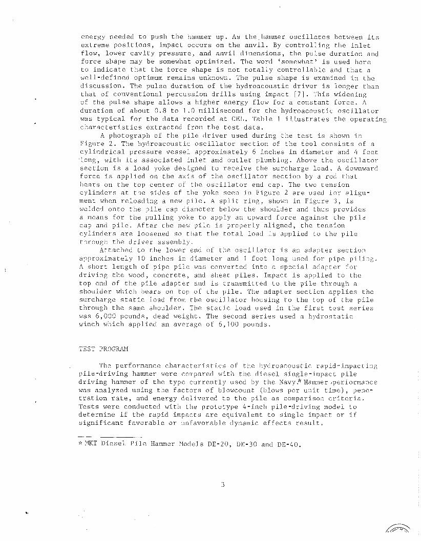
e n e r g y needed t o push t h e hammer up . As t h e hammer o s c i l l a t e s be tween i t s e x t r e m e p o s i t i o n s , impac t o c c u r s on t h e a n v i l . By c o n t r o l l i n g t h e i n l e t f l o w , l o w e r c a v i t y p r e s s u r e , and a n v i l d i m e n s i o n s , t h e p u l s e d u r a t i o n and f o r c e s h a p e may b e somewhat o p t i m i z e d . The word 'somewhat' i s used h e r e t o i n d i c a t e t h a t t h e f o r c e s h a p e i s n o t t o t a l l y c o n t r o l l a b l e and t h a t a w e l l - d e f i n e d optimum r e m a i n s unknown. The p u l s e s h a p e i s examined i n t h e d i s c u s s i o n . The p u l s e d u r a t i o n o f t h e h y d r o a c o u s t i c d r i v e r i s l o n g e r t h a n t h a t o f c o n v e n t i o n a l p e r c u s s i o n d r i l l s u s i n g impact [ 7 ] . T h i s w iden ing o f t h e p u l s e s h a p e a l l o w s a h i g h e r e n e r g y f l o w f o r a c o n s t a n t f o r c e . A d u r a t i o n o f a b o u t 0 . 8 t o 1 . 0 m i l l i s e c o n d f o r t h e h y d r o a c o u s t i c o s c i l l a t o r was t y p i c a l f o r t h e d a t a r e c o r d e d a t CEL. T a b l e 1 i l l u s t r a t e s t h e o p e r a t i n g c h a r a c t e r i s t i c s e x t r a c t e d from t h e t e s t d a t a .
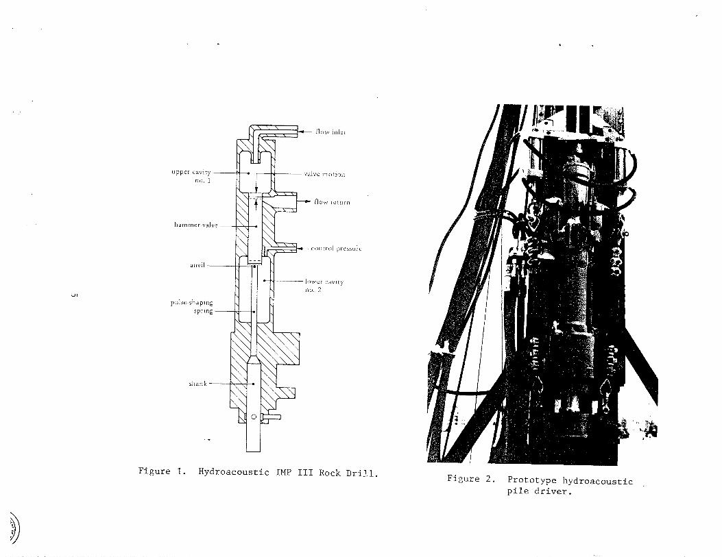
A p h o t o g r a p h o f t h e p i l e d r i v e r u sed d u r i n g t h e t e s t i s shown i n F i g u r e 2 . The h y d r o a c o u s t i c o s c i l l a t o r s e c t i o n of t h e t o o l c o n s i s t s of a c y l i n d r i c a l p r e s s u r e v e s s e l a p p r o x i m a t e l y 6 i n c h e s i n d i a m e t e r and 4 f e e t . l o n g , w i t h i t s a s s o c i a t e d i n l e t and o u t l e t p lumbing . Above t h e o s c i l l a t o r s e c t i o n i s a l o a d yoke d e s i g n e d t o r e c e i v e t h e s u r c h a r g e l o a d . A downward f o r c e i s a p p l i e d on t h e a x i s o f t h e o s c i l l a t o r s e c t i o n by a r o d t h a t b e a r s on t h e t o p c e n t e r of t h e o s c i l l a t o r end c a p . The two t e n s i o n c y l i n d e r s a t t h e s i d e s of t h e yoke s e e n i n F i g u r e 2 a r e used f o r a l i g n - ment when r e l o a d i n g a new p i l e . A s p l i t r i n g , shown i n F i g u r e 3 , i s welded o n t o t h e p i l e c a p d i a m e t e r below t h e s h o u l d e r and t h u s p r o v i d e s a means f o r t h e p u l l i n g yoke t o a p p l y a n upward f o r c e a g a i n s t t h e p i l e c a p and p i l e . A f t e r t h e new p i l e i s p r o p e r l y a l i g n e d , t h e t e n s i o n c y l i n d e r s a r e l o o s e n e d s o t h a t t h e t o t a l l o a d i s a p p l i e d t o t h e p i l e t h r o u g h t h e d r i v e r a s s e m b l y .
A t t a c h e d t o t h e lower end o f t h e o s c i l l a t o r i s a n a d a p t e r s e c t i o n a p p r o x i m a t e l y 1 0 i n c h e s i n d i a m e t e r and 1 f o o t l o n g used f o r p i p e p i l i n g . A s h o r t l e n g t h of p i p e p i l e was c o n v e r t e d i n t o a s p e c i a l a d a p t e r f o r d r i v i n g t h e wood, c o n c r e t e , and s h e e t p i l e s . Impact i s a p p l i e d t o t h e t o p end o f t h e p i l e a d a p t e r and i s t r a n s m i t t e d t o t h e p i l e t h r o u g h a s h o u l d e r which b e a r s on t o p o f t h e p i l e . The a d a p t e r s e c t i o n a p p l i e s t h e s u r c h a r g e s t a t i c l o a d f rom t h e o s c i l l a t o r h o u s i n g t o t h e t o p of t h e p i l e t h r o u g h t h e same s h o u l d e r . The s t a t i c l o a d used i n t h e f i r s t t e s t s e r i e s was 6 , 0 0 0 pounds , dead w e i g h t . The second s e r i e s used a h y d r o s t a t i c winch which a p p l i e d a n a v e r a g e o f 6 , 1 0 0 pounds .
TEST PROGRAT4
The p e r f o r m a n c e c h a r a c t e r i s t i c s of t h e h y d r o a c o u s t i c r a p i d - i m p a c t i n g p i l e - d r i v i n g hammer were compared w i t h t h e d i e s e l s i n g l e - i m p a c t p i l e d r i v i n g hammer o f t h e t y p e c u r r e n t l y u s e d by t h e Navy.*~ammer , pe r fo rmance w a s a n a l y z e d u s i n g t h e f a c t o r s o f b lowcount (b lows p e r u n i t t i m e ) , pene - t r a t i o n r a t e , and e n e r g y d e l i v e r e d t o t h e p i l e as compar i son c r i t e r i a , T e s t s were c o n d u c t e d w i t h t h e p r o t o t y p e 4 - i n c h p i l e - d r i v i n g model t o d e t e r m i n e i f t h e r a p i d i m p a c t s a r e e q u i v a l e n t t o s i n g l e impact o r i f s i g n i f i c a n t f a v o r a b l e o r u n f a v o r a b l e dynamic e f f e c t s r e s u l t .
k?ET D i e s e l P i l e Hammer Pfodels DE-20, DE-30 and DE-40.


F i g u r e 3 , P i l e p u l l i n g c o l l a r .
The i n d i v i d u a l t e s t s conducted by CEL a r e l i s t e d below.*
1 . Closed-end s t e e l p i p e p i l e s 20 f e e t long and 4 i n c h e s , n o m i n a l l y , i n d i a m e t e r w i t h a 5116- inch w a l l t h i c k n e s s , were d r i v e n v e r t i c a l l y t o approx imate ly 15 f e e t below t h e s u r f a c e .
2 . Closed-end s t e e l p i p e p i l e s 40 f e e t long and 4 i n c h e s , n o m i n a l l y , i n d iamete r w i t h a 5116- inch w a l l t h i c k n e s s , were d r i v e n v e r t i c a l l y t o approx imate ly 25 f e e t below t h e s u r f a c e .
3 . Douglas f i r p o s t s , 3 .5 i n c h e s by 3 .5 i n c h e s by 12 f e e t l o n g , were d r i v e n v e r t i c a l l y t o approx imate ly 10 f e e t below t h e s u r f a c e .
4 . Douglas f i r p o s t s , 5 . 5 i n c h e s by 5.5 i n c h e s by 10 f e e t l o n g , were d r i v e n v e r t i c a l l y t o approx imate ly 8 f e e t below t h e s u r f a c e .
5 . Closed-end s t e e l p i p e p i l e s (same a s i t e m 1 above) were d r i v e n i n a b a t t e r p o s i t i o n , i n c l i n e d t o t h e h o r i z o n t a l approx imate ly 6 d e g r e e s , t o a p e n e t r a t i o n d e p t h of 15 f e e t . These t e s t s d r i v e s were d i v i d e d i n t o two p a r t s ; h a l f were d r i v e n i n t o a bank of a d r y e x c a v a t i o n and ha l f were d r i v e n w i t h t h e p i l e and p i l e d r i v e r submerged approx imate ly 2 f e e t under w a t e r i n t h e e x c a v a t i o n .
* Photographs of some of t h e t e s t s a r e i n c l u d e d i n t h e Appendix.

6. Steel-reinforced concrete posts, 5 inches, nominally, in diameter and 12 feet long, were driven vertically to 10 feet below the surface.
7. Closed-end steel pipe piles (same as item 1) except for varying lengths, were driven vertically to depths of 8, 13, and 18 feet and tested for maximum bearing load capacity.
8. Foster type LBF-1707 steel sheet piles 12 feet long were driven vertically to 10 feet below the surface.
The instrumentation used to record each set of data are listed below.
Instrumentation
Longitudinal Strain. The dynamic longitudinal deflections were measured, using two strain gages mounted radially opposite each other with lead wires directly attached to the strain-gage instrumentation. Strain signals were observed continuously during driving. Figure 4 is a schematic of the instrumentation used. Note that the data required are high frequency in nature and that a common high pass filter arrangement was used to stabilize the circuit to obviate the need for a highly sensitive Wheatstone bridge. The circuit was calibrated with a known 125-cps sine wave voltage amplitude input.
Figure 4. Instrumentation schematic.
recorder
filter
a 'r
- 0 a m
- - il - 0
T 3
scope

Driving Velocity. The driving velocity was recorded in the first test series using a stop watch, by timing the penetration of k n o m selected lengths of pile. In the second test series an audio tape recorder was used with a time base playback.
Hydraulic Flow Rate. This was measured with a venturi-type flowmeter in the control panel and was also checked with the flowmeter in the hydraulic power supply. Accuracy of the venturi meter was stated by the manufacturer to be in the range of 25%.
Pressure Drop Across Oscillator. All pressures recorded were measured with standard Bourdon gages in the control panel, with gage lines connected to the points of interest. Equal-length gage lines were used for both input and output oscillator ports to eliminate the in- equality of line pressure drops.
Energy Per Blow. The input energy per blow delivered to the pile was determined from the longitudinal strain pulse measured near the top of the pile. The relationship between the strain and energy may be derived from the longitudinal compression wave equation given below [8].
where u = displacement at the left face of the element dx (see Figure 5)
x = distance from reference fixed in space
dx = elemental length (see Figure 5)
P = density of rod material
t = time
go = conversion factor, 32.1739 lbm ft/sec2 lbf
E = modulus of elasticity
2 = partial derivative
A common solution, known as the characteristic solution, for u as a function of time may be derived from the preceding equation [ 9 ] .
u = f(x - Ct) 4- f'(x 9 Ct) ( 4 )
where C = speed of sound in the rod material = ( E / p ) 1 / 2
f, f' = characteristic curve functions

Figure 5. Element displacement due to longitudinal vibration in a uniform rod.
The velocity (V) of element dx, strain (E), and stress ( 0 ) of a point fixed in the element may then be obtained from the above function of u as follows:
From which the following relations are obtained.
1 / 2 and with C = ( E / p ) ,

As a result, the energy per blow (K) may be determined [ l o ] . I
The force (F) is the product of stress and cross-sectional area and to is the pulse duration.
If the force shape as a function of time is assumed to be a clipped sine wave, the energy calculation is greatly simplified. The computation is relatively accurate for the pulse shapes produced by the hydroacoustic impact tool as may be seen in Figure 6. The resulting approximate energy per blow is:
It is interesting to note that the power flow through element dx is equal to the energy flow rate; i.e., number of blows per second times the energy per blow.

F i g u r e 6 . O s c i l l o g r a p h t r a c i n g o f t y p i c a l f o r c e p u l s e p r o d u c e d by a h y d r o a c o u s t i c i m p a c t t o o l , r e c o r d e d w i t h a s t r a i n gage mounted on a r o t a t i n g d r i l l s t e e l .
O s c i l l a t o r F requency . F requency was r 2 a d i l y d e t e r m i n e d f rom t h e t i m e i n t e r v a l s be tween p u l s e s d i s p l a y e d on t h e o s c i l l o s c o p e .
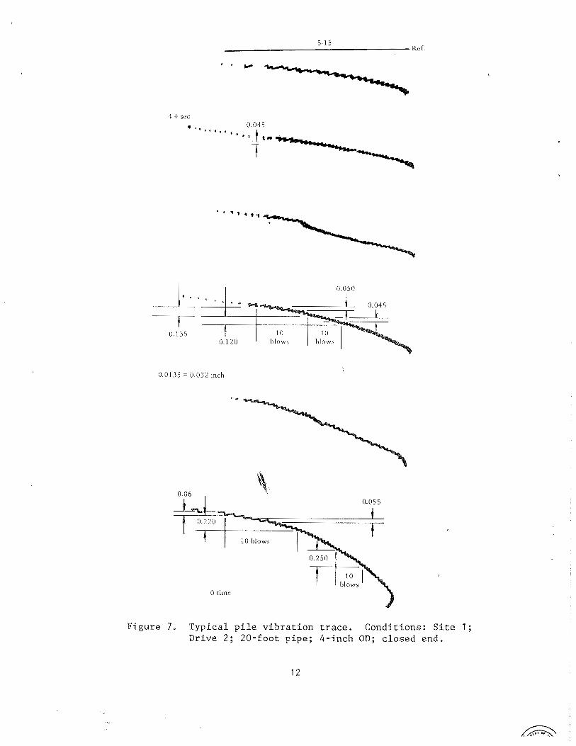
Ampl i tude o f P i l e V i b r a t i o n . Ampl.itude was measured w i t h a d i r e c t t r a c e . I n t h i s method t h e r e c o r d i n g medium was p a p e r which w a s f a s t e n e d d i r e c t l y on t h e p i l e , and a t r a c e was made on i t by r a p i d l y moving a p e n c i l h o r i z o n t a l l y . F i g u r e 7 i l l u s t r a t e s a t y p i c a l t r a c e .
S t a t i c B e a r i n g C a p a c i t y . The b a s i c t e s t p r o c e d u r e i n v o l v e d m e a s u r i n g p i l e s e t t l e m e n t u s i n g e q u a l l o a d i n c r e m e n t s . Each i n c r e m e n t w a s a b o u t o n e - t e n t h o f t h e e s t i m a t e d l o a d needed f o r p r o g r e s s i v e s e t t l e m e n t o f t h e p i l e . The t i m e i n t e r v a l s were 2 m i n u t e s . A c u r v e of l o a d v s s e t t l e m e n t w a s p l o t t e d f rom which t h e c o r n e r w a s p r o j e c t e d a s t h e b e a r i n g l o a d c a p a c i t y [ I l l .
The i n t e r v a l be tween d r i v i n g and b e a r i n g l o a d c a p a c i t y t e s t s was two weeks . The s h o r t d u r a t i o n i s n o t c o n s i d e r e d s i g n i f i c a n t d u e t o t h e c o h e - s i o n l e s s s o i l ( beach s a n d ) used i n t h e t e s t . A l s o , o n l y o n e c y c l e was u n d e r t a k e n f o r t h e t e s t p e r p i l e p r i m a r i l y d u e t o t h e h e a r i n g c a p a c i t y b e i n g t h e s o l e d a t a p o i n t r e q u i r e d .
4 + sec
Figure 7. Typical pile vibration trace. Conditions: Site 1 ; Drive 2; 20-foot pipe; 4-inch OD; closed end.
T e s t R e s u l t s
R e s u l t s a c h i e v e d f rom t h e tes ts and e x a m i n a t i o n o f t h e h y d r o a c o u s t i c p i l e d r i v e r a r e l i m i t e d . Both t e s t s i t e s r e sembled t h a t o f a t y p i c a l s h o r e a r e a . C l a y s found t o b e d e t r i m e n t a l t o v i b r a t o r y d r i v e r s were n o t t e s t e d . I m p l i c a t i o n s of t h e t e s t r e s u l t s and c o n c l u s i o n s drawn f rom them a r e examined more c o m p l e t e l y i n t h e d i s c u s s i o n and c o n c l u s i o n .
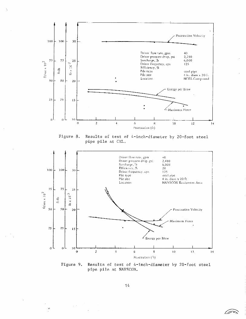
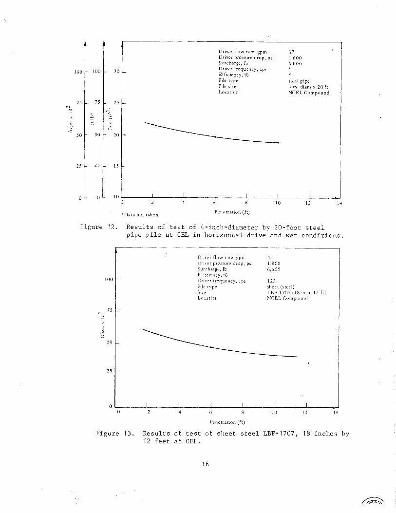
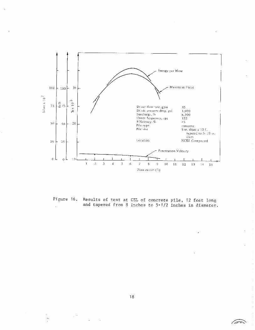
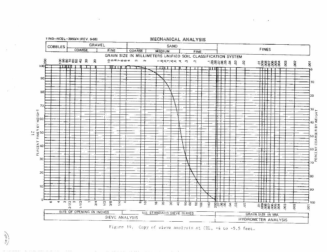
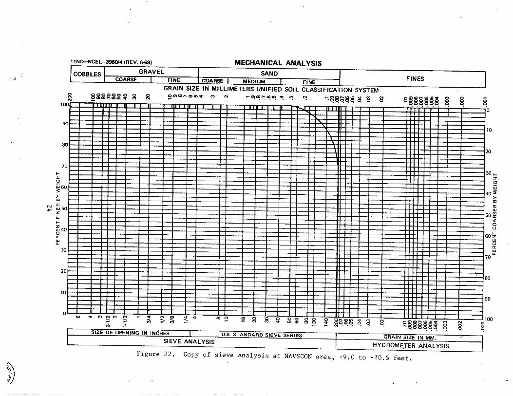
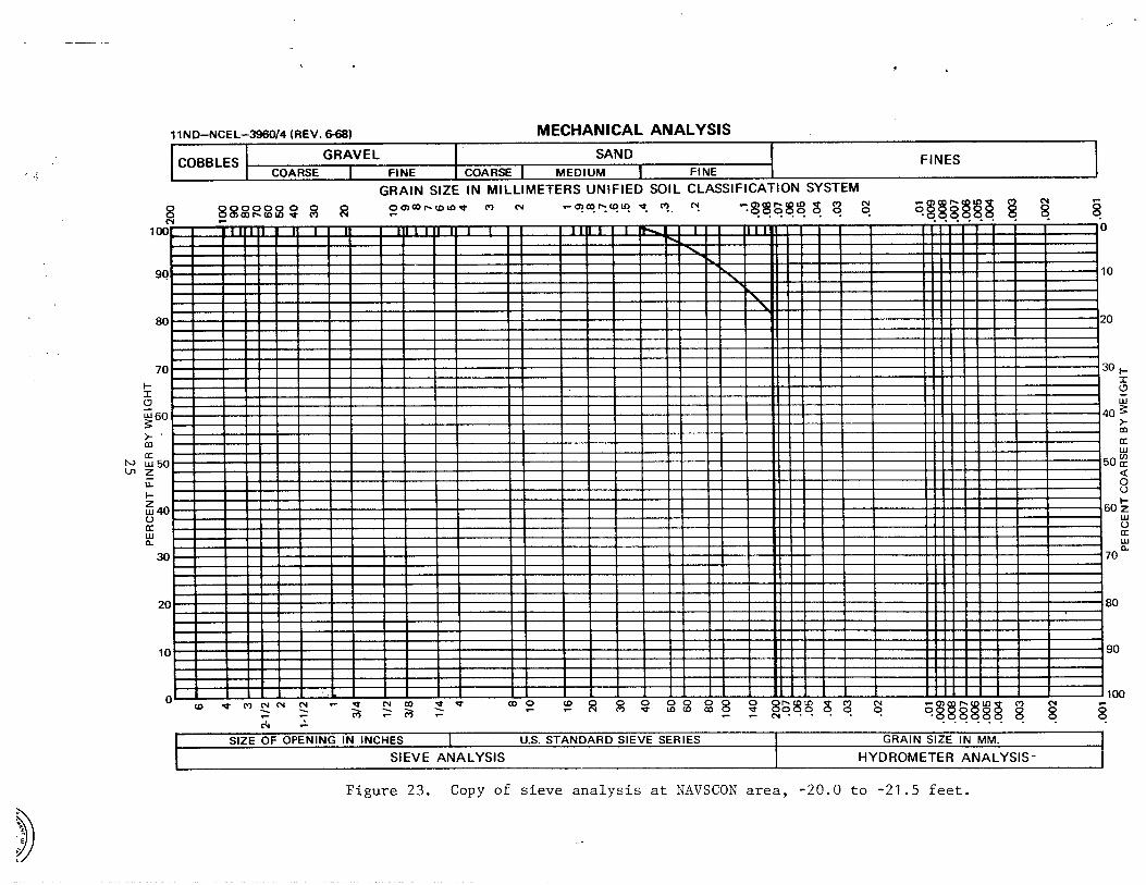
T a b l e 1 i l l u s t r a t e s t h e t y p e of d a t a r e c o r d e d f o r e a c h p i l e d r i v e . F i g u r e s 8 t h r o u g h 16 c o n s i s t o f t y p i c a l d a t a r e c o r d e d f o r e a c h s p e c i f i c t y p e of d r i v i n g t e s t and i l l u s t r a t e t h e e n e r g y , p e n e t r a t i o n v e l o c i t y and maximum f o r c e d e l i v e r e d t o t h e p i l e a s a f u n c t i o n o f p e n e t r a t i o n d e p t h , Below t h e p l o t g r a p h a r e t h e a v e r a g e v a l u e s of o s c i l l a t o r y f r e q u e n c y , p r e s s u r e d r o p a c r o s s t h e d r i v e r , d r i v e r e f f i c i e n c y , f l o w r a t e , and s u r c h a r g e . D r i v e r e f f i c i e n c y i s t h e r a t i o o f t h e mean e n e r g y r a t e r e c o r d e d f rom t h e p i l e o r a d a p t e r d i v i d e d by t h e d r i v e r i n p u t h y d r a u l i c power. F i g u r e s 17 t h r o u g h 24 a r e t h e r e s u l t s of t h e b o r i n g l o g s a t e a c h test s i t e .
The s t a t i c b e a r i n g - l o a d c a p a c i t y d e t e r m i n e d by e x p e r i m e n t d i f f e r e d a p p r e c i a b l y f rom t h e v a l u e c a l c u l a t e d f rom t h e Mod i f i ed E n g i n e e r i n g News (MEN) E q u a t i o n ( 5 ) . A 20 f o o t c l o s e d - e n d p i p e p i l e embedded 16 f e e t v e r t i c a l l y a t t h e CEL compound was found by t e s t t o h a v e a s t a t i c b e a r i n g - l o a d c a p a c i t y o f 22 ,000 pounds . The e n e r g y t r a n s m i t t e d p e r blow t o t h i s p i l e was r e c o r d e d as 65 f t - l b p e r blow w i t h a n e t p i l e p e n e t r a t i o n a m p l i t u d e o f 0 . 0 6 8 i n c h a t 1 6 f e e t . I f t h e p i l e s o i l r e s i s t a n c e were assumed c o n s t a n t and e q u a l t o t h e s t a t i c b e a r i n g l o a d , t h e p i l e would a b s o r b 135 f t - l b . T h i s c l e a r l y i n d i c a t e s t h a t some form of s o i l f l u i d a t i o n o c c u r s p r e c l u d i n g a n y a p p l i c a t i o n o f t h e MEN f o r m u l a . S i m i l a r r e s u l t s we re a l s o found w i t h t h e o t h e r p i l e s t e s t e d .
DISCUSSION
The t e c h n i q u e o f r a p i d l y i m p a c t i n g a p i l e w i t h a t u n e d h y d r o a c o u s t i c hammer i s p r e s e n t l y b e i n g proposed a s a n a i d i n a c h i e v i n g h i g h p i l e - p e n e t r a t i o n r a t e s i n s o i l s . The o b j e c t i v e of t h i s p r o j e c t i s t o i n v e s t i - g a t e t h e i n c r e a s e d pe r fo rmance a c h i e v a b l e u t i l i z i n g r a p i d - i m p a c t i n g p i . l e hammers, t o test and e v a l u a t e a n e x i s t i n g model o f a 4 - i n c h r a p i d - i m p a c t i n g p i l e d r i v e r t o d e t e r m i n e i t s p o t e n t i a l f o r f u r t h e r d e v e l o p m e n t , and t o d e v e l o p a f u l l - s c a l e p r o t o t y p e i f w a r r a n t e d by tes t r e s u l t s . I n t h i s p a p e r a g e n e r a l m a c r o s c o p i c a n a l y t i c a l s t u d y o f t h e s o i l - p i l e r e l a t i o n s h i p i s made t o compare t h e m a j o r p i l e - d r i v i n g t h e o r i e s f rom which some b a s i c c o n c l u s i o n s a r e drawn.
It h a s been p roven t h a t s o i l r e a c t s n o n l i n e a r l y w i t h a r a p i d p i l e - p e n e t r a t i o n r a t e u s i n g h i g h f r e q u e n c y [ 1 2 , 31. Many t h e o r i e s have b e e n enumera t ed based o n s u b s t a n t i a l e x p e r i m e n t a t i o n o v e r t h e p a s t d e c a d e [ 2 , 3 , 6 , 1 2 , 1 3 , 1 4 , 1 5 , 1 6 1 . For t h i s r e a s o n o n l y t h e h i g h l i g h t s o f t h e more g e n e r a l l y a c c e p t e d t h e o r i e s w i l l bc d i s c u s s e d h e r e .
Penetration Velocity
-
Driver flow rate, gpm 40 Driver pressure d rop , psi 2 ,590 Surcharge, Ib 6 , 0 0 0 Driver frequency, cps 1 2 5 Efficiency, % Pile type steel pipe Pile size 4 in. diam x 2 0 f t
• Location NCEL C o n ~ p o u n d . /- Energy per Blow I
1 0 l 1 I I I I I 0 2 4 6 8 10 1 2 1 4
- Penetration ( I t )
Figure 8. Results of test of 4-inch-diameter by 20-foot steel pipe pile at CEL.
Driver tlow ra te , gpm Driver pressure d rop , psi Surcharge, Ib Efhciency, % Driver frequency, cps Pile type Pile size L o c a t ~ o n
40 2,480 6,000 2 0 125 steel pipe 4 in. diam x 2 0 ft NAVSCON, Equipment Area
Penetration ( f t )
Figure 9. Results of test of 4-inch-diameter by 20-foot steel pipe pile at NAVSCON.
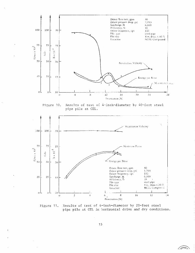
Figure 1 1 . Results of test of 4-inch-diameter by 20-foot steel pipe pile at CEL in horizontal drive and dry conditions.
Driver flow rate, gpm Driver pressure drop, psi Surcharge, Ib Driver frequency, cps Efficiency, % Pile type Pile size Location
steel pipe 4 in. diam x 2 0 ft NCEL Compound
'Data not taken. Pene t r a t~on ( f t )
Figure 12. Results of test of 4-inch-diameter by 20-foot steel pipe pile at CEL in horizontal drive and wet conditions.
Driver flow rate, gpm 4 3 Driver pressure drop, psi 1 , 8 0 0 Surcharge, Ib 6,600 E i i i c~ency , % I l r ~ v < r frequency, cps 1 2 5 Pile type sheet (steel) S I Z Z LBF-1707 ( 1 8 in. x 1 2 f t ) Location NCEL Compound
Penetration ( f t )
Figure 13. Results of test of sheet steel LBF-1707, 18 inches by 12 feet at CEL.

Driver flow rate, gpm Driver pressure drop, psi Surcharge, Ib E f f ~ c i e n c ~ , % Driver f requency, cps Pile type Pile size
- Location
3 8 2,600 6 .000 16 125 wood (Douglas f ~ r ) 3-112 in. x 3-11? in. x 16 f t NCEL Compound
Energy per Blow
-
F i g u r e 14. R e s u l t s of test of Douglas f i r wooden p i l e , 3-112 b y 3-112 i n c h e s by 16 f e e t a t GEL.
I
Energy per Blow
- 3 0
Maximum Force
D r ~ v e r flow rate, gpm
- 2 5 Surcharge, Ib
3 0
4 I 2 5
D r ~ v e r pressure d rop , p s ~ 2 ,560 6,000
? o E f f i c ~ e n c ~ , % - Driver frequency, cps
-0 P ~ l e type wood (Douglas fir) Pile size 5-112 in. x 5-112 111. u l l f r
- 2 0 Location NCEL C o ~ r ~ p o u r ~ d
- 1 5
- 1 0 0 2 4 6 8 1 0 1 2 14
Penetration ( i t )
F i g u r e 15. R e s u l t s of t e s t of Douglas f i r wooden p i l e , 5-112 by 5-112 i n c h e s by 1 1 f e e t a t CEL.
Energy per Blow
Maximum Force
Driver flow race, gpm Driver pressure d rop , psi Surcharge, Ib Driver frequency, cps Efficiency. '% Pile type Pile size
4 5 1,900 6 ,200 122 4 5 concrete 8 in. diam x 1 2 ft
tapered to 5-11:! in diarn
NCEL Cornpound
Pene t r a t~on ( f t )
F igure 1 6 . R e s u l t s of t e s t a t CEL o f c o n c r e t e p i l e , 1 2 f e e t l o n g and t a p e r e d from 8 i n c h e s t o 5 - 1 1 2 i n c h e s i n d i a m e t e r .


\ 2
V)
i 5
2s z
4
w
LT N
W
'
mk
-
Wa
J
aJ fr ,
-=lo
sg
q
>
r. I
' C)
U
0
LP,
E
--- : 3 cu L-2 ?<
;i: P
L
d
Ld
V)
(/I -
UJ
, -
.<; (r: LU
2: m
*J
U1
C
>
i
X 1
-5. a
0: ,--.I
2 I:: i;j
q ?
ti, 2
I .r4
I cr) , j L
l1
O
a m - Z
Ikl
8 LL 0
U1
N
V)

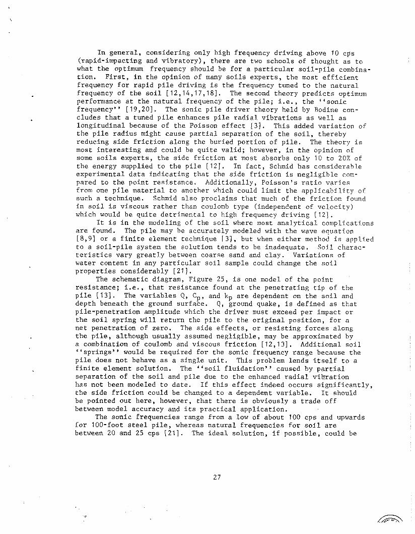
I n g e n e r a l , c o n s i d e r i n g o n l y h i g h f requency d r i v i n g above 10 cps ( r a p i d - i m p a c t i n g and v i b r a t o r y ) , t h e r e a r e two s c h o o l s of thought a s t o what t h e optimum f requency shou ld be f o r a p a r t i c u l a r s o i l - p i l e combina- t i o n . F i r s t , i n t h e o p i n i o n o f many s o i l s e x p e r t s , t h e most e f f i c i e n t f requency f o r r a p i d p i l e d r i v i n g i s t h e f requency tuned t o t h e n a t u r a l f requency o f t h e s o i l [12 ,14 ,17 ,18] . The second t h e o r y p r e d i c t s optimum performance a t t h e n a t u r a l f requency o f t h e p i l e ; i . e . , t h e " s o n i c f requency" [19 ,20] . The s o n i c p i l e d r i v e r t h e o r y h e l d by Bodine con- c l u d e s t h a t a tuned p i l e enhances p i l e r a d i a l v i b r a t i o n s a s w e l l a s l o n g i t u d i n a l because o f t h e Po i sson e f f e c t [ 3 ] . T h i s added v a r i a t i o n of t h e p i l e r a d i u s might c a u s e p a r t i a l s e p a r a t i o n of t h e s o i l , t h e r e b y r e d u c i n g s i d e f r i c t i o n a long t h e b u r i e d p o r t i o n of p i l e . The t h e o r y i s most i n t e r e s t i n g and c o u l d be q u i t e v a l i d ; however, i n t h e o p i n i o n of some s o i l s e x p e r t s , t h e s i d e f r i c t i o n a t most absorbs o n l y 10 t o 20% of t h e energy s u p p l i e d t o t h e p i l e [ 1 2 ] . I n f a c t , Schmid h a s c o n s i d e r a b l e e x p e r i m e n t a l d a t a i n d i c a t i n g t h a t t h e s i d e f r i c t i o n i s n e g l i g i b l e com- pared t o t h e p o i n t r e s i s t a n c e . A d d i t i o n a l l y , P o i s s o n ' s r a t i o v a r i e s from one p i l e m a t e r i a l t o a n o t h e r which could l i m i t t h e a p p l i c a b i l i t y of such a t e c h n i q u e . Schmid a l s o p roc la ims t h a t much of t h e f r i c t i o n found i n s o i l i s v i s c o u s r a t h e r than coulomb t y p e ( independent of v e l o c i t y ) which would b e q u i t e d e t r i m e n t a l t o h igh f requency d r i v i n g [ 1 2 ] .
It i s i n t h e modeling of t h e s o i l where most a n a l y t i c a l c o m p l i c a t i o n s a r e found. The p i l e may be a c c u r a t e l y modeled w i t h t h e wave e q u a t i o n [ 8 , 9 ] o r a f i n i t e e lement t echn ique [ 3 ] , b u t when e i t h e r method i s a p p l i e d t o a s o i l - p i l e sys tem t h e s o l u t i o n t e n d s t o be i n a d e q u a t e . S o i l c h a r a c - t e r i s t i c s v a r y g r e a t l y between c o a r s e sand and c l a y . V a r i a t i o n s of w a t e r c o n t e n t i n any p a r t i c u l a r s o i l sample could change t h e s o i l p r o p e r t i e s c o n s i d e r a b l y [21] .
The schemat ic d iagram, F igure 25, i s one model of t h e p o i n t r e s i s t a n c e ; i . e . , t h a t r e s i s t a n c e found a t t h e p e n e t r a t i n g t i p o f t h e p i l e [ 1 3 ] . The v a r i a b l e s Q , C p , and kp a r e dependent on t h e s o i l and d e p t h benea th t h e ground s u r f a c e . Q , ground quake, i s d e f i n e d a s t h a t p i l e - p e n e t r a t i o n ampl i tude which t h e d r i v e r must exceed p e r impact o r t h e s o i l s p r i n g w i l l r e t u r n t h e p i l e t o t h e o r i g i n a l p o s i t i o n , f o r a n e t p e n e t r a t i o n o f ze ro . The s i d e e f f e c t s , o r r e s i s t i n g f o r c e s a l o n g t h e p i l e , a l t h o u g h u s u a l l y assumed n e g l i g i b l e , may be approximated by a combinat ion of coulomb and v i s c o u s f r i c t i o n [12 ,13] . A d d i t i o n a l s o i l " spr ings" would be r e q u i r e d f o r t h e s o n i c f requency r a n g e because t h e p i l e does n o t behave a s a s i n g l e u n i t . T h i s problem l e n d s i t s e l f t o a f i n i t e e lement s o l u t i o n . The " s o i l f l u i d a t i o n " caused by p a r t i a l s e p a r a t i o n o f t h e s o i l and p i l e due t o t h e enhanced r a d i a l v i b r a t i o n h a s n o t been modeled t o d a t e . I f t h i s e f f e c t indeed o c c u r s s i g n i f i c a n t l y , t h e s i d e f r i c t i o n cou ld be changed t o a dependent v a r i a b l e . It should be p o i n t e d o u t h e r e , however, t h a t t h e r e i s obv ious ly a t r a d e o f f between model accuracy and i t s p r a c t i c a l a p p l i c a t i o n .
The s o n i c f r e q u e n c i e s range from a low of abou t 100 c p s and upwards f o r 100- foo t steel p i l e , whereas n a t u r a l f r e q u e n c i e s f o r s o i l a r e between 20 and 25 cps [ 2 1 ] . The i d e a l s o l u t i o n , i f p o s s i b l e , cou ld be
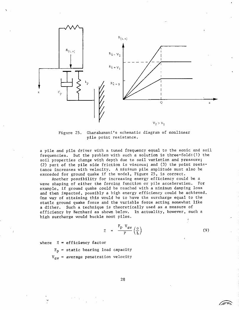
Figure 25. Gharahamani's schematic diagram of nonlinear pile point resistance.
a pile and pile driver with a tuned frequency equal to the sonic and soil frequencies. But the problem with such a solution is three-fold:(l) the soil properties change with depth due to soil variation and pressure; (2) part of the pile side friction is viscous; and (3) the point resis- tance increases with velocity. A minimum pile amplitude must also be exceeded for ground quake if the model, Figure 25, is correct.
Another possibility for increasing energy efficiency could be a wave shaping of either the forcing function or pile acceleration. For example, if ground quake could be reached with a minimum damping loss and then impacted, possibly a high energy efficiency could be achieved. One way of attaining this would be to have the surcharge equal to the static ground quake force and the variable force acting somewhat like a dither. Such a technique is theoretically used as a measure of efficiency by Bernhard as shown below. In actuality, however, such a high surcharge would buckle most piles,
I
where ll = efficiency factor
Fp = static bearing load capacity
Va, = average penetration velocity
P = d r i v e r power i n p u t
p = l e n g t h of p i l e p e n e t r a t i o n
L = l e n g t h of p i l e
The wide ly v a r y i n g s o i l p r o p e r t i e s and t h e e q u a l l y v a r y i n g t h e o r e t i c a l i n t e r p r e t a t i o n s a r e n o t t h e o n l y confus ing c l o u d s c o v e r i n g t h e h o r i z o n of p i l e - d r i v i n g phenomena.
Energy and Power R e l a t i o n s h i p s
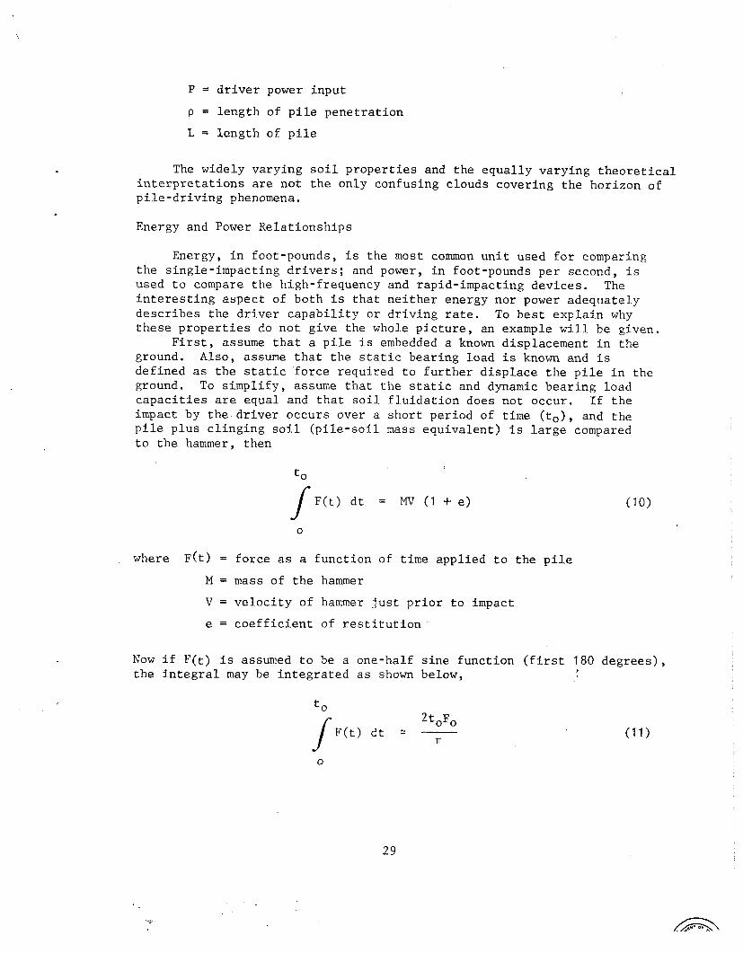
Energy, i n foo t -pounds , i s t h e most common u n i t used f o r comparing t h e s i n g l e - i m p a c t i n g d r i v e r s ; and power, i n foot-pounds p e r second , i s used t o compare t h e h igh- f requency and r a p i d - i m p a c t i n g d e v i c e s . The i n t e r e s t i n g a s p e c t of b o t h i s t h a t n e i t h e r energy n o r power a d e q u a t e l y d e s c r i b e s t h e d r i v e r c a p a b i l i t y o r d r i v i n g r a t e . To b e s t e x p l a i n why t h e s e p r o p e r t i e s do n o t g i v e t h e whole p i c t u r e , an example w i l l be g iven .
F i r s t , assume t h a t a p i l e i s embedded a known d i sp lacement i n t h e ground. Also , assume t h a t t h e s t a t i c b e a r i n g l o a d i s known and i s d e f i n e d a s t h e s t a t i c f o r c e r e q u i r e d t o f u r t h e r d i s p l a c e t h e p i l e i n t h e ground. To s i m p l i f y , assume t h a t t h e s t a t i c and dynamic b e a r i n g l o a d c a p a c i t i e s are e q u a l and t h a t s o i l f l u i d a t i o n does n o t o c c u r . I f t h e impact by t h e . d r i v e r o c c u r s over a s h o r t p e r i o d o f t i m e ( t o ) , and t h e p i l e p l u s c l i n g i n g s o i l ( p i l e - s o i l mass e q u i v a l e n t ) i s l a r g e compared t o t h e hammer, t h e n
where ~ ( t ) = f o r c e as a f u n c t i o n of t i m e a p p l i e d t o t h e p i l e
M = mass of t h e hammer
V = v e l o c i t y o f hammer j u s t p r i o r t o impact
e = c o e f f i c i e n t o f r e s t i t u t i o n
Now i f F ( t ) i s assumed t o be a one-ha l f s i n e f u n c t i o n ( f i r s t 180 d e g r e e s ) , t h e i n t e g r a l may be i n t e g r a t e d a s shown below, #
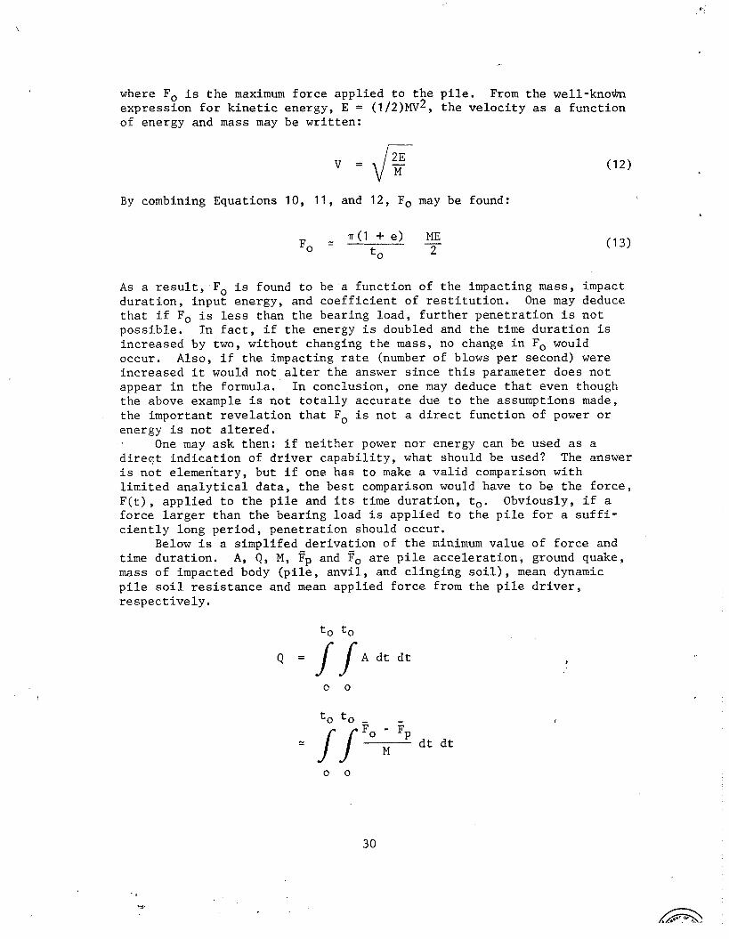
where Fo i s t h e maximum f o r c e appl ied t o t h e p i l e . From t h e w e l l - k n o h express ion f o r k i n e t i c energy, E = (1/2)Plv2, t h e v e l o c i t y a s a func t ion of energy and mass may be w r i t t e n :
By combining Equations 10, 11, and 12, Fo may be found:
As a r e s u l t , Fo i s found t o be a func t ion of t h e impacting mass, impact d u r a t i o n , i npu t energy, and c o e f f i c i e n t of r e s t i t u t i o n . One may deduce t h a t i f Fo i s l e s s than t h e bearing load , f u r t h e r pene t r a t ion i s n o t poss ib l e . I n f a c t , i f t h e energy i s doubled and the time d u r a t i o n i s increased by two, without changing t h e mass, no change i n Fo would occur. Also, i f t h e impacting r a t e (number of blows per second) were increased i t would not a l t e r the answer s i n c e t h i s parameter does n o t appear i n t h e formula. I n conclusion, one may deduce t h a t even though the above example i s no t t o t a l l y accu ra t e due t o t he assumptions made, t he important r e v e l a t i o n t h a t Fo i s no t a d i r e c t func t ion of power o r energy i s no t a l t e r e d .
One may a sk then: i f n e i t h e r power nor energy can be used a s a d i r e q t i n d i c a t i o n of d r i v e r c a p a b i l i t y , what should be used? The answer i s n o t e lementary, but i f one has t o make a v a l i d comparison wi th l i m i t e d a n a l y t i c a l d a t a , t h e bes t comparison would have t o be t h e f o r c e , F ( t ) , app l i ed t o t h e p i l e and i t s time du ra t ion , to. Obviously, i f a fo rce l a r g e r than t h e bear ing load i s app l i ed t o t he p i l e f o r a s u f f i - c i e n t l y long pe r iod , pene t r a t ion should occur.
Below i s a s impl i fed de r iva t ion of t h e minimum value of f o r c e and time du ra t ion . A, Q , M, pp and Fo a r e p i l e a c c e l e r a t i o n , ground quake, mass of impacted body ( p i l e , a n v i l , and c l i n g i n g s o i l ) , mean dynamic p i l e s o i l r e s i s t a n c e and mean appl ied f o r c e from t h e p i l e d r i v e r , r e s p e c t i v e l y .
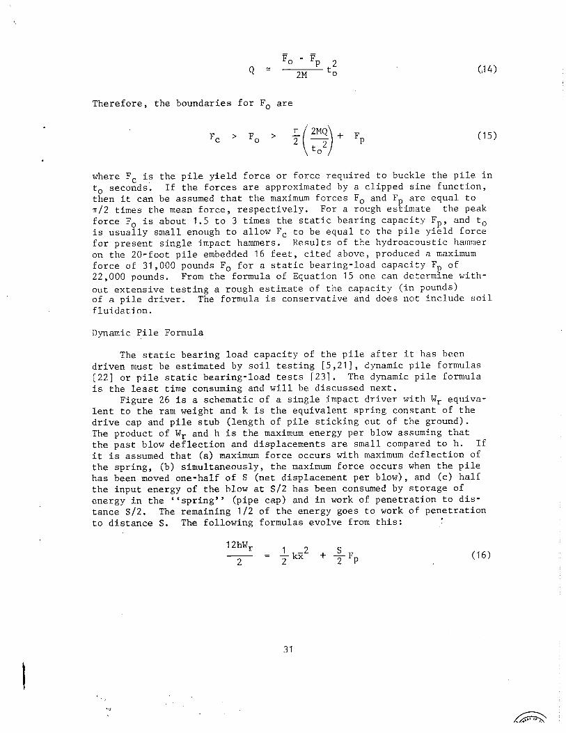
Therefore, the boundaries for Fo are
where Fc is the pile yield force or force required to buckle the pile in to seconds. If the forces are approximated by a clipped sine function, then it can be assumed that the maximum forces Fo and Fp are equal to n/2 times the mean force, respectively. For a rough estimate the peak force Fo is about 1.5 to 3 times the static bearing capacity Fp, and to is usually small enough to allow Fc to be equal to the pile yield force for present single impact hammers. Results of the hydroacoustic hammer on the 20-foot pile embedded 16 feet, cited above, produced a maximum force of 31,000 pourids Fo for a static bearing-load capacity F of P 22,000 pounds. From the formula of Equation 15 one can determine with- out extensive testing a rough estimate of the capacity (in pounds) of a pile dri.ver. The formula is conservative and does not include soil fluidation.
Dynamic Pile Formula
The static bearing load capacity of the pile after it has been driven must be estimated by soil testing [5,21], dynamic pile formulas [22] or pile static bearing-load tests [23]. The dynamic pile formula is the least time consuming and will be discussed next.
Figure 26 is a schematic of a single impact driver with Wr equiva- lent to the ram weight and k is the equivalent spring constant of the drive cap and pile stub (length of pile sticking out of the ground). The product of Wr and h is the maximum energy per blow assuming that the past blow deflection and displacements are small compared to h. If it is assumed that (a) maximum force occurs with maximum deflection of the spring, (b) simultaneously, the maximum force occurs when the pile has been moved one-half of S (net displacement per blow), and (c) half the input energy of the blow at S/2 has been consumed by storage of energy in the "spring" (pipe cap) and in work of penetration to dis- tance S/2. The remaining 112 of the energy goes to work of penetration to distance S. The following formulas evolve from this: I

where 2 i s t h e maximum s p r i n g compression and h i s m u l t i p l i e d by 12 do c o n v e r t a l l terms t o l b - i n . The above e q u a t i o n would be r e p r e s e n t a t i v e of impact i f t h e r e were no impact l o s s e s o r rebound; however, t h i s i s n o t t h e c a s e . Energy l o s s e s must be c o n s i d e r e d ; a commonly used e q u a t i o n f o r impact i s :
where Mr = impac t ing mass
M = impacted mass
V = v e l o c i t y of impac t ing mass
e = c o e f f i c i e n t of r e s t i t u t i o n
It i s assumed t h a t t h e impacted mass v e l o c i t y b e f o r e and a f t e r impact and t h e a s s o c i a t e d k i n e t i c e n e r g i e s a r e n e g l i g i b l e . Equat ion 17 i s s u b t r a c t e d from t h e i n p u t energy 12hWr of Equat ion 16 and i f masses M and Mr a r e conver ted t o we igh t s W and Wr by g , g r a v i t y , t h e f o l l o w i n g e q u a t i o n would evo lve :
Note t h a t W , t h e impacted weigh t , i n most c a s e s should i n c l u d e a p o r t i o n of t h e p i l e d r i v e r weight . F i g u r e 27 ( a l s o found i n Reference 5 , page 135) i s a p l o t of c a l c u l a t e d energy t r a n s m i t t e d t o t h e p i l e v e r s u s energy measured. I n t h i s f i g u r e an inaccuracy e x i s t s because W c o n s i s t s o n l y of t h e p i l e and a n v i l . More a c c u r a t e r e s u l t s , marked w i t h a +, i n c l u d e t h e weight of t h e d r i v e r . W f o r t h e h y d r o a c o u s t i c d r i v e r would c o n s i s t of t h e p i l e weight and a n v i l o n l y and would n o t i n c l u d e t h e we igh t o f t h e d r i v e r housing because t h e r e i s no damper i n t e r c o n n e c t i o n between t h e a n v i l and t h e housing of t h e h y d r o a c o u s t i c d r i v e r [ 4 , 7 , 2 4 , 2 5 ] . A s a r e s u l t , t h e energy l o s s d u r i n g impact i s s l i g h t l y l e s s f o r t h e hydro- a c o u s t i c d r i v e r f o r t h e same c o e f f i c i e n t o f r e s t i t u t i o n .
I f Equat ion 18 i s d i v i d e d by F and i f t h e v a l u e 0.1 i s s u b s t i t u t e d f o r k i ; 2 / ~ ~ and a " f a c t o r o f s a f e t y y ' of 6 i s used on Fp, t h e f o l l o w i n g e q u a t i o n , Modified Engineer ing News (MEN) formula [ 5 ] , r e s u l t s :

Figure 26. Equivalent model of single-impact driver.
0.7 -
0.6 - 0 Vulcan No. 1
0 Vulcan SOC
Vulcan 60C
D Delmag D-12
Delmag D-22
0 Link-Belt 3 1 2
0.4 - Open symbols = pipe piles 0 Link-Belt 520
Closed symbols = H-piles McKiernan-Terry DE-30
= intermediate length McKiernan-Terry DE-40
#
X = W a r d CAL
0.2 0.3 0.4 0.5 0.6 0.7 0.8
Enrhru Ratio,
Max. Manufacturer 's Rating, En
Figure 27. Comparison of impact loss factors from Michigan highway study [ 5 ] .
@ Used by permission of Michigan Department of State Highways and Transportation.

The va lue of 0.1 was e m p i r i c a l l y der ived from f i e l d - t e s t d a t a due t o k and Z being d i f f i c u l t t o measure on si te. The MEN formula i s n o t t h e on ly dynamic formula [5 ,22 ] , but i t i s one of t h e s impler e q u a t i o n s t o work wi th and appears t o have some r e l evance t o t h e t h e o r e t i c a l dynamics involved.
To adapt t h e MEN formula t o t h e hydroacous t ic p i l e d r i v e r , t h e 0.1 cons t an t and c o e f f i c i e n t of r e s t i t u t i o n should be modified from accumu- l a t i o n of f i e l d d a t a f o r each s o i l o r d r i v i n g cond i t i on i n o r d e r t o p r e - h d i c t t h e s t a t i c bear ing- load capac i ty . The u n c e r t a i n t y i n t h e dynamic p i l e formula could n o t be determined from t h e CEL test r e s u l t s because of t he apparen t f l u i d a t i o n of t h e s o i l . The s t a t i c bear ing- load c a p a c i t y Fp i s s i g n i f i c a n t l y g r e a t e r than t h e dynamic shear and f r i c t i o n a l s o i l r e s i s t a n c e when f l u i d a t i o n occurs which n u l l i f i e s t h e assumption made i n t he d e r i v a t i o n t h a t t h e work consumed pe r blow f o r p i l e p e n e t r a t i o n i s equa l t o SFp.
Vibra tory P i l e Dr ive r s
The v i b r a t o r y p i l e d r i v e r does no t use impact a s do t h e s i n g l e - impacting hammers o r hydroacous t ic d r i v e r , but a p p l i e s a s i n u s o i d a l f o r c e on t h e top of t h e p i l e i n combination wi th a surcharge. Note i n Figure 28 t h a t t h e two e c c e n t r i c s a r e phased s o t h a t t h e f o r c e genera ted i s zero i n a l l d i r e c t i o n s except i n t h e v e r t i c a l . The f o r c e F ( t ) app l i ed t o t he p i l e i s given below [26]:
W 2
F ( t ) = Ws + (Wdr) - s i n w t g
where Ws = surcharge
W d r = e c c e n t r i c moment
w = r o t a t i n g v e l o c i t y
t = time
For t h e tandem model 2-60, 240-horsepower motor, t h e maximum f o r c e app l i ed t o t h e p i l e would be:
= 104 tons
and to = 0.033 s e c
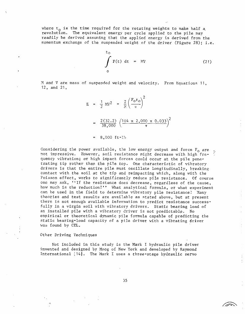
where to i s t h e t i m e r e q u i r e d f o r t h e r o t a t i n g weigh t s t o make h a l f a, r e v o l u t i o n . The e q u i v a l e n t energy p e r c y c l e a p p l i e d t o t h e p i l e may r e a d i l y be d e r i v e d assuming t h a t t h e a p p l i e d energy i s d e r i v e d from t h e momentum exchange of t h e suspended weight of t h e d r i v e r ( F i g u r e 2 8 ) ; i . e .
M and V a r e mass of suspended weight and v e l o c i t y . From Equa t ions 11 , 12, and 2 1 ,
= 8 ,000 f t - l b
Cons ider ing t h e power a v a i l a b l e , t h e low energy ou tpu t and f o r c e Fo a r e 7 n o t impress ive . However, s o i l r e s i s t a n c e might d e c r e a s e w i t h h i g h f r e - .
quency v i b r a t i o n ; o r h igh impact f o r c e s could occur a t t h e p i l e pene- t r a t i n g t i p r a t h e r than t h e p i l e t o p . One c h a r a c t e r i s t i c of v i b r a t o r y d r i v e r s i s t h a t t h e e n t i r e p i l e must o s c i l l a t e l o n g i t u d i n a l l y , b r e a k i n g c o n t a c t w i t h t h e s o i l a t t h e t i p and re impac t ing which, a l o n g w i t h t h e P o i s s o n e f f e c t , works t o s i g n i f i c a n t l y reduce p i l e r e s i s t a n c e . Of c o u r s e one may a s k , " I f t h e r e s i s t a n c e does d e c r e a s e , r e g a r d l e s s of t h e c a u s e , how much i s t h e r e d u c t i o n ? " What a n a l y t i c a l formula , o r what exper iment can be used i n t h e f i e l d t o de te rmine v i b r a t o r y p i l e r e s i s t a n c e ? Many t h e o r i e s and t e s t r e s u l t s a r e a v a i l a b l e a s s t a t e d above, b u t a t p r e s e n t t h e r e i s n o t enough a v a i l a b l e i n f o r m a t i o n t o p r e d i c t r e s i s t a n c e s u c c e s s - f u l l y i n a v i r g i n s o i l w i t h v i b r a t o r y d r i v e r s . S t a t i c b e a r i n g l o a d o f an i n s t a l l e d p i l e w i t h a v i b r a t o r y d r i v e r i s n o t p r e d i c t a b l e . No e m p i r i c a l o r t h e o r e t i c a l dynamic p i l e formula c a p a b l e of p r e d i c t i n g t h e s t a t i c b e a r i n g - l o a d c a p a c i t y of a p i l e d r i v e r w i t h a v i b r a t i n g d r i v e r was found by CEL.
Other D r i v i n g Techniques
Not i n c l u d e d i n t h i s s t u d y i s t h e Mark I h y d r a u l i c p i l e d r i v e r i n v e n t e d and des igned by Moog of New York and developed by Raymond I n t e r n a t i o n a l [ 1 4 ] . The Mark I u s e s a t h r e e - s t a g e h y d r a u l i c s e r v o

surcharge
motor
+ suspension system with vibration suppressor
suspended weight
main chassis
driving head with eccentric weight hydraulic clamp
eccentric weights
center of rotation
radius of gyration
of eccentric weight
F i g u r e 28. Schematic of e c c e n t r i c weight v i b r a t o r y d r i v e r . I
va lve w i t h a p re s su re drop and flow rate capable of up t o 5,000 p s i a t 150 gpm. The device i s s t i l l i n t he t e s t i n g s t a g e , and t h e des ign and test r e s u l t s a r e he ld c o n f i d e n t i a l . One may assume, however, t h a t i f a se rvo v a l v e i s used, f requency, f o r c e wave shape, ampli tude, surcharge and suspended weight could be designed a s v a r i a b l e s and s u b j e c t t o being e a s i l y opt imized. The drawbacks a r e s u s c e p t i b i l i t y t o f a i l u r e s from o i l contaminat ion i n t he se rvo and t h e requirement f o r s o p h i s t i c a t e d e l e c t r i c a l hardware and ope ra to r experience. The r e s u l t s should be made p u b l i c soon and much should be learned t h e r e from.
Another i n t e r e s t i n g p i l e d r i v i n g method could be t o d r i v e t h e p i l e i n w i th a s i n g l e impact. An analogy t o such a technique i s a bow and arrow. A s t r o n g bow can e a s i l y d r i v e a wooden arrow through a l i n e a r yard of sand. I n another example, s t raw has been observed embedded s e v e r a l i nches i n t o hardwood t r e e s a f t e r a tornado. The p r i n c i p l e i s simply t h a t of energy t r a n s f e r ; i . e . , k i n e t i c energy of t h e p i l e u t i l i z e d f o r work i n pene t r a t i on . The problems wi th such a method would be immense due t o high v i scous f r i c t i o n , s a f e t y r i s k s , and t r y i n g t o e s t i - mate p i l e - p e n e t r a t i o n depth and bear ing capac i ty .
CONCLUSIONS
To make a c l e a r - c u t breakdown of a l l t h e known p i l e d r i v e r s and make a s i n g l e s e l e c t i o n of a n i d e a l d r i v e r most a p p l i c a b l e f o r Navy u t i l i z a t i o n i s n o t s imple. There e x i s t s a l a r g e number of t echniques a v a i l a b l e t o d r i v e p i l e s . The approach taken i n t h i s paper was t o group a l l t he va r ious techniques i n t o t h r e e b a s i c ca t ego r i e s : v i b r a t o r y ( sonic and non-sonic) , rap id- impact ing , and s ing le - impact ing . Obviously t h e r e i s an a r b i t r a r y d i s t i n c t i o n between r ap id - and s ing le - impact ing , Rapid- impact ing i s assumed he re t o have an impacting r a t e above 20 cps , a range which i n c l u d e s t h e n a t u r a l f requenc ies of s o i l .
Of a l l t h e known d r i v e r s on ly t h e d i e s e l and Bodineys engine-mounted son ic v i b r a t o r y d r i v e r a r e s e l f - con ta ined . The remaining p i l e d r i v e r s r e q u i r e a power supply; i . e . , e l e c t r i c , steam, pneumatic, o r hyd rau l i c . The Bodine d r i v e r e s s e n t i a l l y has i t s power supply mounted on t h e d r i v e r and weighs cons iderab ly more than a d i e s e l . Making a comparison us ing a d imens ionless r a t i o of t h e maximum p i l e - d r i v i n g bear ing- load c a p a b i l i t y Fp t o t h e weight of d r i v e r p l u s a u x i l i a r y equipment, t h e d i e s e l would f a r e w e l l ; however, sh ipp ing weight i s only one f a c t o r .
Another f a c t o r i s t h e d r i v i n g r a t e , o r more p r a c t i c a l l y , t h e t o t a l t i m e t o d r i v e t he p i l e , which inc ludes se t -up time. The problem wi th comparing d r i v i n g r a t e s i s t h a t they a r e c l o s e l y dependent upon t h e s o i l composi t ion, most no t i ceab ly wi th v i b r a t o r y d r i v e r s . S o i l f l u i d a t i o n can g r e a t l y enhance p e n e t r a t i o n r a t e . Unfor tuna te ly , i t i s d i f f i c u l t t o p r e d i c t . In f a c t , v i s cous f o r c e s sometimes a t t e n u a t e p e n e t r q t i o n of h igh-v ibra tory- f requency d r i v e r s but do no t a f f e c t s ing le - impact ing d r i v e r s . The rap id- impact ing hydroacous t ic hammer has n o t experienced
viscous effects strong enough to stop penetration, but tests with the , driver are few. Results from this test program were impressive, never- theless, with the hydroacoustic driver averaging 30 ftlmin penetration rate for wood and steel, and 12 ftlmin for concrete. Diesel driving in similar soil by CEL averaged 2.5 ftlmin for wood and 1.6 ftlmin for concrete [ 4 ] . During CEL tests, set-up time took as long as driving time.
The rapid-impacting hydroacoustic pile driver produced a high force on the pile which was rudimentarily derived in Equation 15 in the dis- cussion as the primary parameter for predicting capacity. Also, no special adapter is required on the pile with the impact drivers, single or rapid. The pile static bearing load is roughly predictable with single-impact drivers using dynamic pile formulas. The hydroacoustic driver is a tuned single-frequency driver, and experimentation by alter- ing frequency and impact amplitude is not possible without significantly changing driver hardware. This does not necessarily detract from the device, because one principle advantage is its simplicity of having only one moving part.
The final comparison factor and probably most important is cost effectiveness. This is, as one may expect, the most difficult to cal- culate. The hydroacoustic driver tested is an experimental model and not an operational full-scale driver. Many problems that may be encountered in the field are unknown. Consequently, a detailed analysis [ 2 6 ] is not given here. If it is assumed that maintenance, down time, and required number of operators are roughly the same for hydroacoustic and diesel hammers, a general comparison can be made. Actually, this assumption is reasonably accurate due to the similar mechanical complexity of each and the manner in which the drivers are used. The set-up time is also about the same, between 10 and 20 minutes per pile. The hydro- acoustic driver, averaging 25 to 3 0 ftlmin, could decrease total time per pile by 50% for penetration depths of 25 feet. With three operating personnel, two riggers and one crane operator, the cost saving per pile (at $10 per man-hour) would be between $10 and $15. Cost savings would rise even more with increased penetration depths.
It appears to this observer that considerable information is still needed before a complete analysis can be made to select a single optimum pile driver. However, from all the literature and experimentation to date, the rapid-impacting technique of driving piles appears most prom- mising.
RECOMMENDATIONS
It is highly recommended that the Navy finance a continued investi- gation of new pile-driving approaches to stay abreast with the, latest developments. It is also recommended that an in-house research program be financed to determine which pile-driving parameters are important and how to verify a pile-driver capacity without extensive field tests. The
program need not be expensive and should rely heavily n test data resulting with empirical formulas capable of determining the following, specific information:
1. Relationship between pile cross-sectional area, driving rate and ground quake.
2. Dynamic pile formula validity with respect to vibratory and rapid-impacting drivers.
3. Effects of soil fluidation on rapid-impacting hammer.
4 . Longitudinal power flow attenuation as a function of penetration depth.
5. Rapid-impacting pile velocity versus dynamic soil resistance.
It is urged that the program produce techniques or test procedures to adequately determine the minimum capabilities of a pile driver. A detailed analytical study should be left for academic institutions.
It will not be necessary to expend Navy funds to finance development of a full-scale prototype hydroacoustic driver since this will be done by Raymond International. Raymond is also doing extensive research with the Mark I high-frequency servo driver. A combination of these two R&D projects plus continual improvements of the diesel should adequately produce or finalize proper selection of the best driver or group of pile drivers suitable for Navy needs. This, however, does not mean that the Navy should discontinue research in this important area.
Appendix
PHOTOGRAPHS OF PILE D R I V I N G TESTS

Figure 29. Sheet p i l e d r i v i n g tes t , j u s t p r i o r t o d r i v e .
F igure 30. Concrete p i l e d r i v i n g test, j u s t p r i o r t o d r i v e .

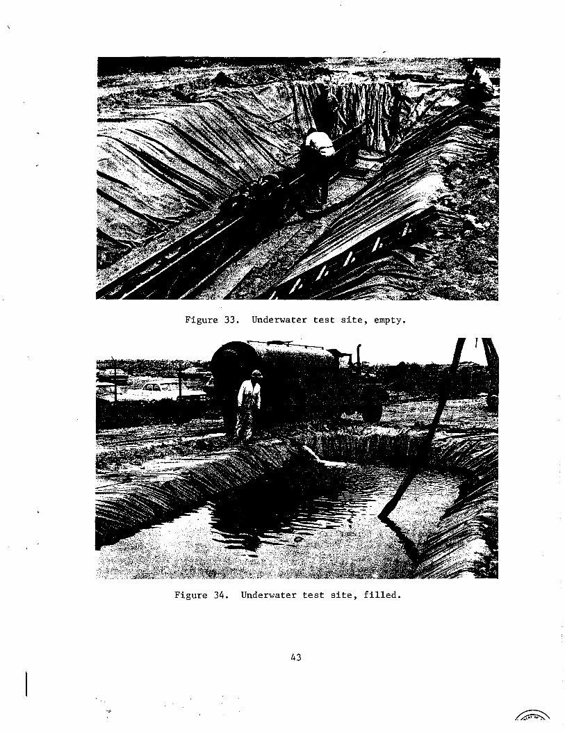
Figure 33. Underwater test site, empty.
Figure 34. Underwater test site, filled.
1 REFERENCES
1. "Vibratory pile driver looks good," Western Construction, No. 240, May 1965.
2. Naval Facilities Engineering Command, Chesapeake Division. A Com- parison of current and projected methods of driving piles, by A. Rinakli. Washington, D.C., Oct. 1970.
3. Army Corps of Engineers. SR 141: Pile driving by means of longitudinal and torsional vibration, by Austin Kovacs and Frank Michitti. July 1970.
4. Naval Civil Engineering Laboratory. Technical Report R-088: Evaluation of the McKiernan Terry DE20 Diesel Pile Hammer, by J. J. Hromadik. Port Hueneme, CAY 1960.
5. Michigan State Highway Commission. RP 61F-60: A performance investi- gation of pile driving hammers and piles, by A. W. Ferguson. Lansing, MI, Mar 1965.
6. General Dynamics Corp., Electronics Division. Report No. HL110-69: Comparison of hydroacoustic impact drivers with resonant eccentric weight pile drivers, by B. A. Wise. June 1967.
. Report No. AC117-70: The IMP-M percussion rock drill with 7 .- independent rotation, by B. A. Wise. Oct. 1970.
8. R. M. Phelan. Dynamics of machinery. New York, McGraw-Hill Book Co., 1967..
9. I. S. Sokolnikoff and R. M. Redheffer. Mathematics of physics and modern engineering. New York, McGraw-Hill Book Co., 1966.
10. W. W. Hagerty and H. J. Place. Engineering mechanics, New York, D. Van Nostrand Co., Inc., 1962.
/
11. A. S. Vesic. ccInvestigations of bearing capacity of piles in sand,'9 North American Conference on Deep Foundations, Mexico City, Dec. 1964.
12. Princeton University. Princeton Soil Engineering Research Series No No. 4: The driving of piles by longitudinal vibrations, by W. E. Schmid and H. J. Hill. Princeton, New Jersey, 1966.
13.- . Princeton Soil Engineering Research Series No. 11: Vibratory pile driving and ultimate penetration, by W. E. Schmid and A. Gharahamani. princeton, NJ. I
14. Moog Servocontrols Inc. Proposal No. ID-64012: Proposal of electro- hydraulic oscillatory hammer for Raymond International, Inc. East Aurora, NY, Sept. 1964.
, 15. R. K. Bernhard. "Pile-soil interactions during vibro-pile-driving," Journal of Materials, JMLSA, vol. 3, No. 1, 1968, pp. 178-209.
-- 16. M. Senator. "Vibratory penetration of soils," American Society of Mechanical Engineers, 1967 (Paper No. 67-Vibro-24). I
17. Naval Civil Engineering Laboratory. Technical Note N-483: Pile driving by vibrations, by R. J. Lowe. Port Hueneme, CAY 1963.
18. D. D. Barkan. "Foundation engineering and drilling by the vibration method," in Proceedings of the Fourth International Conference on Soil Mechanics and Foundation Engineering, London, Vol. 2, 1957, pp 3 - 7 .
19. U. S. Patent No. 2,975,846: Acoustic method and apparatus for driving piles, by A. G. Bodine. Mar. 21, 1961.
20. Army Cold Regions Research and Engineering Laboratory. Vibratory pile driving and coring in permafrost, by R. W. Huck. Hanover, NH, Nov. 1969.
21. B. K. Hough. Basic soils engineering. New York, The Ronald Press CO., 1957. .
22. R. E. Olson and K. S. Flaate. "Pile-driving formulas for friction piles in sand," Journal of the Soil Mechanics Foundation Division, Vol. 93, No. SM6, Nov. 1967.
23. W. Kjellman and Y. Liljedahl. "Device and procedure for loading tests on piles," in Royal Swedish Geotechnical Institute Proceedings No. 3, Stockholm, 1951.
24. MKT Corporation. Manual No. 11-65: MKT Corporation operating maintenance parts manual, Dover, NJ.
25. L. B. Foster Company. Catalog 405-7171: Data on pile drivers and extractors-vibratory, diesel and airlsteam. Seven Parkway Center, Pittsburgh, PA.
26. Naval Civil Engineering Laboratory. Technical Note N-1014: A hand tool selection procedure for Navy construction battalions, by B. C. Witherspoon. Port Hueneme, CA, 1969.

DISTRIBUTION LIST
SNDL No. of Code Activities
FKAIC 1
FKNI 6
FKNS 9
FA25 1
Total Copies
Defense Documentation Center
Naval Facilities Engineering Command
NAVFAC Engineering Field Divisions
Public Works Centers
Public Works Center
RDT&E Liaison Officers at NAVFAC Engineering Field Divisions and Construction Battalion Centers
CEL Special Distribution List No. 8 for persons and activities interested in reports on Mechanical Systems