this copy is for information only. you must purchase the proposal...
TRANSCRIPT

STATE OF DELAWARE
DEPARTMENT OF TRANSPORTATIONJACK MARKELL PO BOX 778 CLEON L. CAULEY, SR
GOVERNOR DOVER, DELAWARE 19903 ACTING SECRETARY
VIA OVERNIGHT DELIVERY (302) 760-2030
FAX (302) 739-2254
May 12, 2011
Contract No. T200809003.01
Federal Aid Project No. IM-N056(35)
SR1/I-95 INTERCHANGE
New Castle County
Ladies and Gentlemen:
Enclosed is Addendum No. 4 for the referenced contract consisting of the following:
NOTE: Technical questions concerning Addendum 4 will be entertained until noon on May 20,
2011.
The date for the receipt of bids remains THURSDAY, May 26, 2011. Bids will be
received until 2:00 P.M., Local Time, the Bidder's Room (B1.11.01), in the DelDOT
Transportation Administration Center, 800 Bay Road, U.S. Route 113 South, Dover,
DE.
1. One (1) page, Bid Proposal Cover, revised, to be substituted for the same page in the
Proposal.
2. One (1) page, Location/Description, page i, revised, to be substituted for the same page in
the Proposal.
3. Six (6) pages, Table of Contents, pages iii through viii, revised, to be substituted for the
same pages in the Proposal.
4. Item Number 623002 , DELETED, to be removed from the Proposal.
5. Two (2) pages, General Notices, pages 1 through 2, revised, to be substituted for the same
THIS COPY IS FOR INFORMATION ONLY. YOU MUST PURCHASE THE PROPOSAL IN ORDER TO SUBMIT A BID.
pages in the Proposal and one (1) page, page 2A, new, to be added to the Proposal..
6. One (1) page, Critical DBE Requirement, page 13, revised, to be substituted for the same
page in the Proposal.
7. One (1) page, State of Delaware Prevailing Wages, page 33, revised, to be substituted for
the same page in the Proposal.
8. Four (4) pages, Special Provisions, 602616 - Waterproofing PCC Masonry Surfaces, pages
89A through 89D, new, to be added to the Proposal.
9. Seven (7) pages, Special Provisions, 602772 - Mechanically Stabilized Earth Walls, pages
92 through 97A, revised, to be substituted for the same pages in the Proposal.
10. Nine (9) pages, Special Provisions, 602774 - Masonry For Light Pole Foundation (CY),
pages 99 through 107, revised, to be substituted for the same pages in the Proposal.
11. Twelve (12) pages, Special Provisions, 605500 - Cantilever-Sign Support and Foundation,
pages 128 through 139, revised, to be substituted for the same pages in the Proposal.
12. Twelve (12) pages, Special Provisions, 605523 - Box Truss Type Overhead Sign Supports
and Foundations, pages 142 through 153, revised, to be substituted for the same pages in the
Proposal.
13. One (1) page, Special Provisions, 619501 - Production Pile Restrike, page 184, new, to be
added to the Proposal.
14. Four (4) pages, Special Provisions, 619519 - Dynamic Pile Testing By Contractor, pages
185 through 188, revised, to be substituted for the same pages in the Proposal.
15. One (1) page, Special Provisions, 720512 - P. C. C. Safety Barrier Permanent, Double Face,
page 200, revised, to be substituted for the same page in the Proposal.
16. Two (2) pages, Special Provisions, 720532 - Install Portable Impact Attenuator, pages 205
through 206, revised, to be substituted for the same pages in the Proposal.
17. Two (2) pages, Special Provisions, 744520 - Conduit Junction Well, pages 227 through 228,
revised, to be substituted for the same pages in the Proposal.
18. Four (4) pages, Special Provisions, 746519 - Aluminum Light Standard With Single Davit
Arm, 40' Pole, pages 242 through 245, revised, to be substituted for the same pages in the
Proposal.
19. One (1) page, Special Provisions, 746537 - Relocating Existing Light Standards, page 246,
revised, to be substituted for the same page in the Proposal.
20. One (1) page, Special Provisions, 746592 - Replace/Adapt Existing Transformer Bases, page
248, revised, to be substituted for the same page in the Proposal.
21. Two (2) pages, Special Provisions, 746620 - Relocation of Existing Lighting Tower, pages

251 through 252, revised, to be substituted for the same pages in the Proposal.
22. Five (5) pages, Special Provisions, 746621 - Lighting Towers and Installation, pages 253
through 257, revised, to be substituted for the same pages in the Proposal.
23. Three (3) pages, Special Provisions, 746717 - Electric Service on Pedestal with Service
Riser, pages 260 through 262, revised, to be substituted for the same pages in the Proposal.
24. Six (6) pages, Special Provisions, 759501 - Field Office, Special, pages 309 through 314,
revised, to be substituted for the same pages in the Proposal.
25. One (1) page, Special Provisions, 763564 - Special Bidding Procedure, page 340, revised,
to be substituted for the same page in the Proposal.
26. Five (5) pages, Utility Statement, revised, to be substituted for the same pages in the
Proposal.
27. Thirty-Two (32) pages, Bid Proposal Forms, pages 1 through 32, revised, to be substituted
for the same pages in the Proposal.
28. One (1) page, Bid Proposal Forms/Breakout Sheet 2A, Item 602772 - Mechanically
Stabilized Earth Walls, revised, to be substituted for the same page in the Proposal.
29. One (1) page, Bid Proposal Forms/Breakout Sheet 13, Item 605757 - High Performance
Steel, revised, to be substituted for the same page in the Proposal.
30. Three (3) items, Break-out Sheets, Bid Proposal Forms, items 207501, 720532, and 720534,
DELETED, to be removed from the Proposal.
31. Two (2) pages, Form Sheets, item 720532 - Install Portable Impact Attenuator and item
720534 - Furnish Portable Impact Attenuator, new, to be added to the Proposal.
32. One (1) page, Diesel Fuel Cost Price Adjustment Option, revised, to be substituted for the
same page in the Proposal.
33. Ninety-five (95) sheets, Construction Plans, sheets 4, 5, 76, 77, 78, 79, 196, 198, 208, 210,
215, 219, 223, 226, 227, 255, 257, 267, 269, 271, 308, 310, 320, 322, 323, 350, 352, 363,
367, 369, 370, 373, 395, 397, 408, 410, 451, 452, 453, 454, 455, 456, 457, 458, 461, 461A,
465, 466, 467, 468, 469, 473, 474, 476, 477A, 478, 486, 487, 488, 493, 495, 504, 514, 518,
522, 525, 533, 537, 542, 546, 551, 555, 559, 570, 575, 583, 590, 596, 602, 610, 619, 624,
625, 670, 685, 699, 700, 700A, 701, 703, 704, 706, 707, 709A, and 710, revised, to be
substituted for the same sheets in the Plan Set, two (2) sheets, sheets 462A and 477A1, new,
to be added to the Plan Set, and two (2) sheets, sheets 462 and 477, DELETED, to be
removed from the Plan Set.
34. For proposal holders with the electronic bid option only, Amendment Disk No. 3.
Please note the revisions listed above and submit your bid based upon this information.
Sincerely,
Scott S. Gottfried
Competitively Bid Contracts Coordinator
:ssg
Enclosures
STATE OF DELAWARE
DEPARTMENT OF TRANSPORTATION
BID PROPOSAL
for
CONTRACT T200809003.01
FEDERAL AID PROJECT NO. IM-N056(35)
SR1/I-95 INTERCHANGENEW CASTLE COUNTY
PROSPECTIVE BIDDERS ARE ADVISED THAT THERE WILL BE A MANDATORY PRE-BID MEETING FOR
THIS CONTRACT ON JANUARY 12 14, 2011 at 10:30 A.M. IN THE DelDOT ADMINISTRATION CENTER, 800
BAY ROAD, U.S. ROUTE 113 SOUTH, DOVER, DELAWARE, 19903 DELAWARE TECHNICAL AND COMMUNITY
COLLEGE, STANTON CAMPUS CONFERENCE CENTER, 400 STANTON-CHRISTIANA ROAD, NEWARK,DE 19713 .
Completion Date 763564 - SPECIAL BIDDING PROCEDURES
SPECIFICATIONS FOR ROAD AND BRIDGE CONSTRUCTIONDELAWARE DEPARTMENT OF TRANSPORTATION
AUGUST 2001
Bids will be received in the Bidder's Room, Transportation Administration Center, 800 Bay Road, Dover,
Delaware until 2:00 P.M. local time, THURSDAY, MAY 26, 2011.
Addendum No. 4May 12, 2011
Addendum No. 4May 12, 2011
Contract No.T200809003.01
Federal Aid Project No. IM-N056(35)
SR1/I-95 INTERCHANGENEW CASTLE COUNTY
LOCATION
These improvements are located in NEW CASTLE County more specifically shown on the Location Map(s)of the enclosed Plans.
DESCRIPTION
The improvements consist of furnishing all labor and materials. This project is part of an overall turnpikeimprovement program to reduce congestion at the SR 1 / I-95 interchange. Construction of a new multiple-laneinterchange will reduce the traffic weaving around the Christiana Mall, SR 1, and I-95 areas. The project will separateout local traffic movements from high speed movements., and other incidental construction in accordance with thelocation, notes and details shown on the plans and as directed by the Engineer.
COMPLETION DATE
All work on this contract must be complete in accordance with the date as determined by Special Provision763564 - SPECIAL BIDDING PROCEDURES.
It is the Department's intent to issue a Notice to Proceed such that work starts on or about September 12, 2011.
ELECTRONIC BIDDING
This project incorporates the electronic bidding system Expedite 5.2b. Bidders wishing to use the electronicbidding option will find a bid file on the CD. The installation software may be downloaded by clicking here.
PROSPECTIVE BIDDERS NOTES:
1. No retainage will be withheld on this contract.
2. The Department has adopted an External Complaint Procedure. The procedure can be viewed on our website at;www.deldot.gov/information/business/, or you may request a copy by calling (302) 760-2555.
3. Please note the Special Provision titled Changes to Project Documents During Advertisement. The Departmentis using an alternative method of providing bid documents for this contract.
4. Please note there are TRAINEES required for this project, and proposed Trainee Plans must be submitted asrequired. Number of required programs is listed in the Training Special Provisions within Contract General Notices. The program(s) must be submitted within 10 Calendar Days of notification of apparent low bidder status. ContractAward will not take place until acceptable On-the-Job (OJT) program plans are received by the Civil Rights Groupof the Department. Failure of the apparent low bidder to present copies of acceptable OJT Trainee Programswithin 10 Calendar Days of notification of apparent low bidder status shall create a non-rebuttablepresumption that the bid is non-responsive.
5. SUBMISSION REMINDER:a. Copy(ies) of the American Traffic Safety Services Association (ATSSA) Certification(s) when listed in
the applicable plan notes. b. Standard Specification Section 110.08 Site Reviewer requires that the name and DNREC certification
number of each Site Reviewer if required shall be submitted to the Department. The level of certificationand number required are listed in the applicable plan notes.
Note: Items a. and b. above require copies of the current certifications for those individuals proposed for useon this Contract.
Failure of the apparent low bidder to present copies of the required certifications within ten (10) calendar days afterthe bid opening shall create a non-rebuttable presumption that the bid is non-responsive.
i
Addendum No. 4May 12, 2011
LOCATION . . . . . . . . . . . . . . . . . . . . . . . . . . . . . . . . . . . . . . . . . . . . . . . . . . . . . . . . . . . . . . . . . . . . . . . . i
DESCRIPTION . . . . . . . . . . . . . . . . . . . . . . . . . . . . . . . . . . . . . . . . . . . . . . . . . . . . . . . . . . . . . . . . . . . . . i
CONSTRUCTION ITEMS UNITS OF MEASURE . . . . . . . . . . . . . . . . . . . . . . . . . . . . . . . . . . . . . . . ii
GENERAL NOTICES . . . . . . . . . . . . . . . . . . . . . . . . . . . . . . . . . . . . . . . . . . . . . . . . . . . . . . . . . . . . . . . 1CONTRACT LIQUIDATED DAMAGES . . . . . . . . . . . . . . . . . . . . . . . . . . . . . . . . . . . . . . . . . . . . . 1CONSTRUCTION PHASING . . . . . . . . . . . . . . . . . . . . . . . . . . . . . . . . . . . . . . . . . . . . . . . . . . . . . 2ASPECIFICATIONS . . . . . . . . . . . . . . . . . . . . . . . . . . . . . . . . . . . . . . . . . . . . . . . . . . . . . . . . . . . . . . . 3CLARIFICATIONS . . . . . . . . . . . . . . . . . . . . . . . . . . . . . . . . . . . . . . . . . . . . . . . . . . . . . . . . . . . . . . . 3ATTESTING TO NON-COLLUSION . . . . . . . . . . . . . . . . . . . . . . . . . . . . . . . . . . . . . . . . . . . . . . . . 3QUANTITIES . . . . . . . . . . . . . . . . . . . . . . . . . . . . . . . . . . . . . . . . . . . . . . . . . . . . . . . . . . . . . . . . . . . 3REQUIREMENT BY DEPARTMENT OF LABOR FOR SWORN PAYROLL INFORMATION . 3PREFERENCE FOR DELAWARE LABOR . . . . . . . . . . . . . . . . . . . . . . . . . . . . . . . . . . . . . . . . . . . 4CONFLICT WITH FEDERAL STATUTES OR REGULATIONS . . . . . . . . . . . . . . . . . . . . . . . . . . 4EQUALITY OF EMPLOYMENT OPPORTUNITY ON PUBLIC WORKS . . . . . . . . . . . . . . . . . . . 4TAX CLEARANCE . . . . . . . . . . . . . . . . . . . . . . . . . . . . . . . . . . . . . . . . . . . . . . . . . . . . . . . . . . . . . . 5LICENSE . . . . . . . . . . . . . . . . . . . . . . . . . . . . . . . . . . . . . . . . . . . . . . . . . . . . . . . . . . . . . . . . . . . . . . . 5TO REPORT BID RIGGING ACTIVITIES . . . . . . . . . . . . . . . . . . . . . . . . . . . . . . . . . . . . . . . . . . . . 5CONVICT PRODUCED MATERIALS: . . . . . . . . . . . . . . . . . . . . . . . . . . . . . . . . . . . . . . . . . . . . . . 5NOTICE OF REQUIREMENT FOR AFFIRMATIVE ACTION TO ENSURE EQUAL EMPLOYMENT
OPPORTUNITY (EXECUTIVE ORDER 11246) . . . . . . . . . . . . . . . . . . . . . . . . . . . . . . 5STANDARD FEDERAL EQUAL EMPLOYMENT OPPORTUNITY CONSTRUCTION CONTRACT
SPECIFICATIONS (EXECUTIVE ORDER 11246) . . . . . . . . . . . . . . . . . . . . . . . . . . . . 6TRAINING SPECIAL PROVISIONS . . . . . . . . . . . . . . . . . . . . . . . . . . . . . . . . . . . . . . . . . . . . . . . 9INTERMODAL SURFACE TRANSPORTATION EFFICIENCY ACT & TRANSPORTATION
EQUITY ACT . . . . . . . . . . . . . . . . . . . . . . . . . . . . . . . . . . . . . . . . . . . . . . . . . . . . . . . . 11DISADVANTAGED BUSINESS ENTERPRISE (DBE) PROGRAM SPECIFICATION . . . . . . . 11CRITICAL DBE REQUIREMENTS . . . . . . . . . . . . . . . . . . . . . . . . . . . . . . . . . . . . . . . . . . . . . . . . 13GUIDANCE FOR GOOD FAITH EFFORT . . . . . . . . . . . . . . . . . . . . . . . . . . . . . . . . . . . . . . . . . . . 14REQUIRED CONTRACT PROVISIONS FEDERAL-AID CONSTRUCTION CONTRACTS . . . 15
I. GENERAL . . . . . . . . . . . . . . . . . . . . . . . . . . . . . . . . . . . . . . . . . . . . . . . . . . . . . . . . . 15II. NONDISCRIMINATION . . . . . . . . . . . . . . . . . . . . . . . . . . . . . . . . . . . . . . . . . . . . 16III. NONSEGREGATED FACILITIES . . . . . . . . . . . . . . . . . . . . . . . . . . . . . . . . . . . . 19IV. PAYMENT OF PREDETERMINED MINIMUM WAGE . . . . . . . . . . . . . . . . . . 19V. STATEMENTS AND PAYROLLS . . . . . . . . . . . . . . . . . . . . . . . . . . . . . . . . . . . . . 24VI. RECORD OF MATERIALS, SUPPLIES, AND LABOR . . . . . . . . . . . . . . . . . . . 25VII. SUBLETTING OR ASSIGNING THE CONTRACT . . . . . . . . . . . . . . . . . . . . . . 26VIII. SAFETY: ACCIDENT PREVENTION . . . . . . . . . . . . . . . . . . . . . . . . . . . . . . . . 26IX. FALSE STATEMENTS CONCERNING HIGHWAY PROJECTS . . . . . . . . . . . 26X. IMPLEMENTATION OF CLEAN AIR ACT AND FEDERAL WATER POLLUTION
CONTROL ACT . . . . . . . . . . . . . . . . . . . . . . . . . . . . . . . . . . . . . . . . . . . . . . . . 27XI. CERTIFICATION REGARDING DEBARMENT, SUSPENSION, INELIGIBILITY
AND VOLUNTARY EXCLUSION . . . . . . . . . . . . . . . . . . . . . . . . . . . . . . . . . 27XII. CERTIFICATION REGARDING USE OF CONTRACT FUNDS FOR LOBBYING
. . . . . . . . . . . . . . . . . . . . . . . . . . . . . . . . . . . . . . . . . . . . . . . . . . . . . . . . . . . . . 30DIFFERING SITE CONDITIONS . . . . . . . . . . . . . . . . . . . . . . . . . . . . . . . . . . . . . . . . . . . . . . . . . . 31PREVAILING WAGES . . . . . . . . . . . . . . . . . . . . . . . . . . . . . . . . . . . . . . . . . . . . . . . . . . . . . . . . . . 32PREVAILING WAGE REQUIREMENTS . . . . . . . . . . . . . . . . . . . . . . . . . . . . . . . . . . . . . . . . . . . . 32PREVAILING WAGE DETERMINATION - Highway Construction . . . . . . . . . . . . . . . . . . . . . . . 33
GENERAL DECISION: DE100013 5/21/2010 DE13.........................................................................34APPLICABILITY OF DAVIS-BACON LABOR STANDARD PROVISIONS TO FLAGGERS . 35ALL AGENCY MEMORANDUM NO. 130 . . . . . . . . . . . . . . . . . . . . . . . . . . . . . . . . . . . . . . . . . . 36
SUPPLEMENTAL SPECIFICATIONS . . . . . . . . . . . . . . . . . . . . . . . . . . . . . . . . . . . . . . . . . . . . . . . . . 37
SPECIAL PROVISIONS . . . . . . . . . . . . . . . . . . . . . . . . . . . . . . . . . . . . . . . . . . . . . . . . . . . . . . . . . . . . 39CONSTRUCTION ITEM NUMBERS . . . . . . . . . . . . . . . . . . . . . . . . . . . . . . . . . . . . . . . . . . . . . . . 41
iii
Addendum No. 4May 12, 2011
CHANGES TO PROJECT DOCUMENTS DURING ADVERTISEMENT . . . . . . . . . . . . . . . 42MODIFICATIONS TO REQUIRED FEDERAL CONTRACT PROVISIONS . . . . . . . . . . . . . . . . 43401502 - ASPHALT CEMENT COST ADJUSTMENT . . . . . . . . . . . . . . . . . . . . . . . . . . . . . . . . . 44202505 – SETTLEMENT PLATFORM . . . . . . . . . . . . . . . . . . . . . . . . . . . . . . . . . . . . . . . . . . . . . . 45202518 – SETTLEMENT MONUMENT . . . . . . . . . . . . . . . . . . . . . . . . . . . . . . . . . . . . . . . . . . . . . 45202514 – PIEZOMETER . . . . . . . . . . . . . . . . . . . . . . . . . . . . . . . . . . . . . . . . . . . . . . . . . . . . . . . . . 49202555 - SUBSOIL TILLAGE . . . . . . . . . . . . . . . . . . . . . . . . . . . . . . . . . . . . . . . . . . . . . . . . . . . . . 55208500 - FLOWABLE FILL . . . . . . . . . . . . . . . . . . . . . . . . . . . . . . . . . . . . . . . . . . . . . . . . . . . . . . . 57209510 - CONTROLLED LOW STRENGTH MATERIAL (CLSM) . . . . . . . . . . . . . . . . . . . . . . . 59211521 – ABANDONMENT OF WELLS . . . . . . . . . . . . . . . . . . . . . . . . . . . . . . . . . . . . . . . . . . . . 62211523 – REMOVAL OF P.C.C. BARRIER . . . . . . . . . . . . . . . . . . . . . . . . . . . . . . . . . . . . . . . . . . 63401654 - SUPERPAVE, TYPE B HOT-MIX, 160 GYRATIONS, PG 70-22 . . . . . . . . . . . . . . . . . 64401660 - SUPERPAVE, TYPE B HOT-MIX, 160 GYRATIONS, PG 76-22 . . . . . . . . . . . . . . . . . 64401663 - SUPERPAVE, BITUMINOUS CONCRETE BASE COURSE, 160 GYRATIONS, PG 64-22
. . . . . . . . . . . . . . . . . . . . . . . . . . . . . . . . . . . . . . . . . . . . . . . . . . . . . . . . . . . . . . . . . . . . 64401665 - SUPERPAVE, TYPE C HOT-MIX, 160 GYRATIONS, PG 64-22, PATCHING . . . . . . 64401666 - SUPERPAVE, TYPE B HOT-MIX, 160 GYRATIONS, PG 64-22, PATCHING . . . . . . 64401667 - SUPERPAVE, BITUMINOUS CONCRETE BASE COURSE, 160 GYRATIONS, PG-64-22,
PATCHING . . . . . . . . . . . . . . . . . . . . . . . . . . . . . . . . . . . . . . . . . . . . . . . . . . . . . . . . . . 64401668 - SUPERPAVE, TYPE C HOT-MIX, 160 GYRATIONS, PG-64-22, WEDGE . . . . . . . . . 64401669 - SUPERPAVE, TYPE B HOT-MIX, 160 GYRATIONS, PG-64-22, WEDGE . . . . . . . . . 64401708 - SUPERPAVE, TYPE C HOT-MIX, 160 GYRATIONS, PG 70-22, (NON-CARBONATE
STONE) . . . . . . . . . . . . . . . . . . . . . . . . . . . . . . . . . . . . . . . . . . . . . . . . . . . . . . . . . . . . . 64401711 - SUPERPAVE, TYPE C HOT-MIX, 160 GYRATIONS, PG 76-22, (NON-CARBONATE
STONE) . . . . . . . . . . . . . . . . . . . . . . . . . . . . . . . . . . . . . . . . . . . . . . . . . . . . . . . . . . . . . 64401699 - QUALITY CONTROL/QUALITY ASSURANCE OF BITUMINOUS CONCRETE . . . 70601502 - TEMPORARY PROTECTIVE SHIELD . . . . . . . . . . . . . . . . . . . . . . . . . . . . . . . . . . . . . . 86602579 - DRILLING HOLES AND INSTALLING DOWELS . . . . . . . . . . . . . . . . . . . . . . . . . . . . 88602580 - PARTIAL REMOVAL OF PCC MASONRY . . . . . . . . . . . . . . . . . . . . . . . . . . . . . . . . . . 89
602616 - WATERPROOFING PCC MASONRY SURFACES. . . . . . . . . . . . . . . . . . . . . . . . . . . . 89A 602717 - REHABILITATION OF CONCRETE STRUCTURE, PIERS AND ABUTMENTS . . . . 90602772 - MECHANICALLY STABILIZED EARTH WALLS . . . . . . . . . . . . . . . . . . . . . . . . . . . . 92602773 - PCC MASONRY FOR MECHANICALLY STABILIZED EARTH WALLS . . . . . . . . . 98602774 - MASONRY FOR LIGHT POLE FOUNDATION (CY) . . . . . . . . . . . . . . . . . . . . . . . . . . 99602779 - POST-TENSIONING GROUT . . . . . . . . . . . . . . . . . . . . . . . . . . . . . . . . . . . . . . . . . . . . 108602785 – PORTLAND CEMENT CONCRETE MASONRY, SUBSTRUCTURE 6,000 PSI . . . 111602786 – PORTLAND CEMENT CONCRETE MASONRY, SUBSTRUCTURE 8,000 PSI . . . 112602787 - POST-TENSIONED PIER CAP BONDED SYSTEM . . . . . . . . . . . . . . . . . . . . . . . . . . 113605002 - STEEL STRUCTURES . . . . . . . . . . . . . . . . . . . . . . . . . . . . . . . . . . . . . . . . . . . . . . . . . . 127605500 – CANTILEVER-SIGN SUPPORT AND FOUNDATION . . . . . . . . . . . . . . . . . . . . . . . . 128605511 - PREFABRICATED EXPANSION JOINT SYSTEM 3O . . . . . . . . . . . . . . . . . . . . . . . . 140605512 - PREFABRICATED EXPANSION JOINT SYSTEM 4O . . . . . . . . . . . . . . . . . . . . . . . . 140605513 - PREFABRICATED EXPANSION JOINT SYSTEM 5O . . . . . . . . . . . . . . . . . . . . . . . . 140605523 - BOX TRUSS TYPE OVERHEAD SIGN SUPPORTS AND FOUNDATIONS . . . . . . 142605537 - URETHANE PAINT SYSTEM, NEW STEEL . . . . . . . . . . . . . . . . . . . . . . . . . . . . . . . . 154605581 - ELASTOMERIC BEARING PADS . . . . . . . . . . . . . . . . . . . . . . . . . . . . . . . . . . . . . . . . 159605658 - STRIP SEAL EXPANSION JOINT 2O . . . . . . . . . . . . . . . . . . . . . . . . . . . . . . . . . . . . . . 160605750 - NON-GUIDED POT BEARING AT ABUTMENT . . . . . . . . . . . . . . . . . . . . . . . . . . . . 162605751 - GUIDED POT BEARING AT ABUTMENT . . . . . . . . . . . . . . . . . . . . . . . . . . . . . . . . . 162605752 - NON-GUIDED POT BEARING AT PIER . . . . . . . . . . . . . . . . . . . . . . . . . . . . . . . . . . . 162605753 - GUIDED POT BEARING AT PIER . . . . . . . . . . . . . . . . . . . . . . . . . . . . . . . . . . . . . . . . 162605754 - FIXED POT BEARING AT PIER . . . . . . . . . . . . . . . . . . . . . . . . . . . . . . . . . . . . . . . . . . 162605757 – HIGH PERFORMANCE STEEL . . . . . . . . . . . . . . . . . . . . . . . . . . . . . . . . . . . . . . . . . . 169612529 - PIPE VIDEO INSPECTION . . . . . . . . . . . . . . . . . . . . . . . . . . . . . . . . . . . . . . . . . . . . . . 172612535 - CLEANING DRAINAGE PIPE, 15O - 24O DIA. . . . . . . . . . . . . . . . . . . . . . . . . . . . . . . 174612536 - CLEANING DRAINAGE PIPE, GREATER THAN 24O DIA. . . . . . . . . . . . . . . . . . . . 174612537 - HEAVY CLEANING OF DRAINAGE PIPE . . . . . . . . . . . . . . . . . . . . . . . . . . . . . . . . . 175614605 - STEEL CASING PIPE, 12" . . . . . . . . . . . . . . . . . . . . . . . . . . . . . . . . . . . . . . . . . . . . . . . 180617515 - HEADWALL . . . . . . . . . . . . . . . . . . . . . . . . . . . . . . . . . . . . . . . . . . . . . . . . . . . . . . . . . . 181618540 – FURNISH STEEL PIPE PILES, 24” . . . . . . . . . . . . . . . . . . . . . . . . . . . . . . . . . . . . . . . . 182
iv
Addendum No. 4May 12, 2011
618541 – FURNISH STEEL PIPE PILES, 30” . . . . . . . . . . . . . . . . . . . . . . . . . . . . . . . . . . . . . . . . 182618542 – FURNISH STEEL PIPE PILES, 36” . . . . . . . . . . . . . . . . . . . . . . . . . . . . . . . . . . . . . . . . 182618543 – FURNISH STEEL PIPE TEST PILES, 24” . . . . . . . . . . . . . . . . . . . . . . . . . . . . . . . . . . 182618544 – FURNISH STEEL PIPE TEST PILES, 30” . . . . . . . . . . . . . . . . . . . . . . . . . . . . . . . . . . 182618545 – FURNISH STEEL PIPE TEST PILES, 36” . . . . . . . . . . . . . . . . . . . . . . . . . . . . . . . . . . 182618546 – INSTALLATION OF STEEL PIPE PILES, 24” . . . . . . . . . . . . . . . . . . . . . . . . . . . . . . . 183618547 – INSTALLATION OF STEEL PIPE PILES, 30” . . . . . . . . . . . . . . . . . . . . . . . . . . . . . . . 183618548 – INSTALLATION OF STEEL PIPE PILES, 36” . . . . . . . . . . . . . . . . . . . . . . . . . . . . . . . 183618549 – INSTALLATION OF STEEL PIPE TEST PILES, 24” . . . . . . . . . . . . . . . . . . . . . . . . . 183618550 – INSTALLATION OF STEEL PIPE TEST PILES, 30” . . . . . . . . . . . . . . . . . . . . . . . . . 183618551 – INSTALLATION OF STEEL PIPE TEST PILES, 36” . . . . . . . . . . . . . . . . . . . . . . . . . 183619501 - PRODUCTION PILE RESTRIKE . . . . . . . . . . . . . . . . . . . . . . . . . . . . . . . . . . . . . . . . . . 184619502 - TEST PILE RESTRIKE . . . . . . . . . . . . . . . . . . . . . . . . . . . . . . . . . . . . . . . . . . . . . . . . . . 184619519 – DYNAMIC PILE TESTING BY CONTRACTOR . . . . . . . . . . . . . . . . . . . . . . . . . . . . . 185619539 – SIGNAL MATCHING ANALYSIS BY CONTRACTOR . . . . . . . . . . . . . . . . . . . . . . . 185623002 - PRESTRESSED REINFORCED CONCRETE MEMBERS, BOX BEAMS . . . . . . . . . 187708500 - REPLACING CATCH BASIN GRATES . . . . . . . . . . . . . . . . . . . . . . . . . . . . . . . . . . . . 189708504 - REPLACING CATCH BASIN FRAMES . . . . . . . . . . . . . . . . . . . . . . . . . . . . . . . . . . . . 189708512 – DRAINAGE INLET, SPECIAL I . . . . . . . . . . . . . . . . . . . . . . . . . . . . . . . . . . . . . . . . . . 190708513 – DRAINAGE INLET, SPECIAL II . . . . . . . . . . . . . . . . . . . . . . . . . . . . . . . . . . . . . . . . . 190708515 – DRAINAGE INLET, SPECIAL IV . . . . . . . . . . . . . . . . . . . . . . . . . . . . . . . . . . . . . . . . . 190708516 – DRAINAGE INLET, SPECIAL V . . . . . . . . . . . . . . . . . . . . . . . . . . . . . . . . . . . . . . . . . 190708517 – DRAINAGE INLET, SPECIAL VI . . . . . . . . . . . . . . . . . . . . . . . . . . . . . . . . . . . . . . . . . 190708518 – DRAINAGE INLET, SPECIAL VII . . . . . . . . . . . . . . . . . . . . . . . . . . . . . . . . . . . . . . . . 190708653 – DRAINAGE INLET, SPECIAL VIII . . . . . . . . . . . . . . . . . . . . . . . . . . . . . . . . . . . . . . . 190708654 – DRAINAGE INLET, SPECIAL IX . . . . . . . . . . . . . . . . . . . . . . . . . . . . . . . . . . . . . . . . . 190708655 – DRAINAGE INLET, SPECIAL X . . . . . . . . . . . . . . . . . . . . . . . . . . . . . . . . . . . . . . . . . 190708656 – DRAINAGE INLET, SPECIAL XI . . . . . . . . . . . . . . . . . . . . . . . . . . . . . . . . . . . . . . . . . 190708537 - REMOVE CATCH BASIN . . . . . . . . . . . . . . . . . . . . . . . . . . . . . . . . . . . . . . . . . . . . . . . 191708579 – ABANDON EXISTING MANHOLE . . . . . . . . . . . . . . . . . . . . . . . . . . . . . . . . . . . . . . . 192708582 – MANHOLE, SPECIAL I . . . . . . . . . . . . . . . . . . . . . . . . . . . . . . . . . . . . . . . . . . . . . . . . . 193708596 - MANHOLE, SPECIAL II . . . . . . . . . . . . . . . . . . . . . . . . . . . . . . . . . . . . . . . . . . . . . . . . 193708597- MANHOLE, SPECIAL III . . . . . . . . . . . . . . . . . . . . . . . . . . . . . . . . . . . . . . . . . . . . . . . . 193708583 - PERSONNEL GRATE FOR PIPE INLET . . . . . . . . . . . . . . . . . . . . . . . . . . . . . . . . . . . 194712531 - CHANNEL BED FILL . . . . . . . . . . . . . . . . . . . . . . . . . . . . . . . . . . . . . . . . . . . . . . . . . . . 195715500 - UNDERDRAIN OUTLET PIPE, 6O . . . . . . . . . . . . . . . . . . . . . . . . . . . . . . . . . . . . . . . . 196715506 - TEMPORARY DRAINAGE PIPE, 24" . . . . . . . . . . . . . . . . . . . . . . . . . . . . . . . . . . . . . . 197715507 - TEMPORARY DRAINAGE PIPE, 36" . . . . . . . . . . . . . . . . . . . . . . . . . . . . . . . . . . . . . . 197720506 - RELOCATING PORTABLE P.C.C. SAFETY BARRIER . . . . . . . . . . . . . . . . . . . . . . . 199720512 - P.C.C. SAFETY BARRIER PERMANENT, DOUBLE FACE . . . . . . . . . . . . . . . . . . . 200720651 - P.C.C. SAFETY BARRIER PERMANENT, DOUBLE FACE BIFURCATED TYPE 1
. . . . . . . . . . . . . . . . . . . . . . . . . . . . . . . . . . . . . . . . . . . . . . . . . . . . . . . . . . . . . . . . . . . 200720652 - P.C.C. SAFETY BARRIER PERMANENT, DOUBLE FACE BIFURCATED TYPE 2
. . . . . . . . . . . . . . . . . . . . . . . . . . . . . . . . . . . . . . . . . . . . . . . . . . . . . . . . . . . . . . . . . . . 200720654 - P.C.C. SAFETY BARRIER PERMANENT, SINGLE FACE, MODIFIED TYPE 1 . . . 200720655 - P.C.C. SAFETY BARRIER PERMANENT, SINGLE FACE, MODIFIED TYPE 2 . . . 200720656 - P.C.C. SAFETY BARRIER PERMANENT, SINGLE FACE, MODIFIED TYPE 3 . . . 200720657 - P.C.C. SAFETY BARRIER PERMANENT, SINGLE FACE, MODIFIED TYPE 4 . . . 200720658 - P.C.C. SAFETY BARRIER PERMANENT, SINGLE FACE, MODIFIED TYPE 5 . . . 200720517 - IMPACT ATTENUATOR, TYPE I . . . . . . . . . . . . . . . . . . . . . . . . . . . . . . . . . . . . . . . . . 201720527 - PLASTIC DRUMS . . . . . . . . . . . . . . . . . . . . . . . . . . . . . . . . . . . . . . . . . . . . . . . . . . . . . . 202720532 - INSTALL PORTABLE IMPACT ATTENUATOR . . . . . . . . . . . . . . . . . . . . . . . . . . . . 205720534 - FURNISH PORTABLE IMPACT ATTENUATOR . . . . . . . . . . . . . . . . . . . . . . . . . . . . 205720539 - RELOCATE PORTABLE IMPACT ATTENUATOR . . . . . . . . . . . . . . . . . . . . . . . . . . 205720544 - REFLECTORS, WHITE, CONCRETE . . . . . . . . . . . . . . . . . . . . . . . . . . . . . . . . . . . . . . 207720545 - REFLECTORS, YELLOW, CONCRETE . . . . . . . . . . . . . . . . . . . . . . . . . . . . . . . . . . . . 207720552 - REFLECTOR PANELS . . . . . . . . . . . . . . . . . . . . . . . . . . . . . . . . . . . . . . . . . . . . . . . . . . 208720567 - FURNISH AND MAINTAIN PORTABLE P.C.C. SAFETY BARRIER . . . . . . . . . . . . 209720585 - GUARDRAIL END TREATMENT ATTENUATOR, TYPE 1 . . . . . . . . . . . . . . . . . . . 211720612 - IMPACT ATTENUATOR, SPECIAL . . . . . . . . . . . . . . . . . . . . . . . . . . . . . . . . . . . . . . . 213
v
Addendum No. 4May 12, 2011
727520 - CONSTRUCTION SAFETY FENCE . . . . . . . . . . . . . . . . . . . . . . . . . . . . . . . . . . . . . . . 214735533 - SOIL RETENTION BLANKET MULCH, TYPE 3 . . . . . . . . . . . . . . . . . . . . . . . . . . . . 215735534 - SOIL RETENTION BLANKET MULCH, TYPE 4 . . . . . . . . . . . . . . . . . . . . . . . . . . . . 215735535 - SOIL RETENTION BLANKET MULCH, TYPE 5 . . . . . . . . . . . . . . . . . . . . . . . . . . . . 215735536 - SOIL RETENTION BLANKET MULCH, TYPE 6 . . . . . . . . . . . . . . . . . . . . . . . . . . . . 215736502 - MOWING . . . . . . . . . . . . . . . . . . . . . . . . . . . . . . . . . . . . . . . . . . . . . . . . . . . . . . . . . . . . . 217737527 - INTERCHANGE TREE PLANTING . . . . . . . . . . . . . . . . . . . . . . . . . . . . . . . . . . . . . . . 218743501 - WARNING LIGHTS, TYPE B . . . . . . . . . . . . . . . . . . . . . . . . . . . . . . . . . . . . . . . . . . . . 223743504 - WARNING SIGNS . . . . . . . . . . . . . . . . . . . . . . . . . . . . . . . . . . . . . . . . . . . . . . . . . . . . . 223743507 - TEMPORARY BARRICADES, TYPE III . . . . . . . . . . . . . . . . . . . . . . . . . . . . . . . . . . . 223743524 - TEMPORARY BARRICADES, TYPE III . . . . . . . . . . . . . . . . . . . . . . . . . . . . . . . . . . . 223743525 - TEMPORARY WARNING SIGNS . . . . . . . . . . . . . . . . . . . . . . . . . . . . . . . . . . . . . . . . . 223743537 - FURNISH AND MAINTAIN TRUCK-MOUNTED ATTENUATOR, TYPE II . . . . . . 226744506 - CONDUIT JUNCTION WELL, TYPE 7, 36" x 60" PRECAST POLYMER CONCRETE
. . . . . . . . . . . . . . . . . . . . . . . . . . . . . . . . . . . . . . . . . . . . . . . . . . . . . . . . . . . . . . . . . . . 227744520 - CONDUIT JUNCTION WELL, TYPE 1, 20" x 20" PRECAST CONCRETE . . . . . . . . 227744523 - CONDUIT JUNCTION WELL, TYPE 4, 20" x 42 ½" PRECAST CONCRETE . . . . . . 227744505 - ADJUST OR REPAIR EXISTING CONDUIT JUNCTION WELL . . . . . . . . . . . . . . . 229744525 - REMOVAL OF EXISTING JUNCTION WELL . . . . . . . . . . . . . . . . . . . . . . . . . . . . . . 230744529 – P.C.C. BARRIER, JUNCTION WELL . . . . . . . . . . . . . . . . . . . . . . . . . . . . . . . . . . . . . . 231745521 - SUPPLY OF 4" SDR-13.5 HDPE CONDUIT . . . . . . . . . . . . . . . . . . . . . . . . . . . . . . . . . 232745524 - SUPPLY OF 4" SCHEDULE 80 PVC CONDUIT . . . . . . . . . . . . . . . . . . . . . . . . . . . . . 232745526 - SUPPLY OF 3" GALVANIZED STEEL CONDUIT . . . . . . . . . . . . . . . . . . . . . . . . . . . 232745527 - SUPPLY OF 2 1/2" GALVANIZED STEEL CONDUIT . . . . . . . . . . . . . . . . . . . . . . . . 232745528 - SUPPLY OF 2" GALVANIZED STEEL CONDUIT . . . . . . . . . . . . . . . . . . . . . . . . . . . 232745529 - SUPPLY OF 1 1/2" GALVANIZED STEEL CONDUIT . . . . . . . . . . . . . . . . . . . . . . . . 232745530 - SUPPLY OF 1" GALVANIZED STEEL CONDUIT . . . . . . . . . . . . . . . . . . . . . . . . . . . 232745531 - SUPPLY OF 3/4" GALVANIZED STEEL CONDUIT . . . . . . . . . . . . . . . . . . . . . . . . . . 232745537 - SUPPLY OF 3/4" FLEXIBLE METALLIC-LIQUIDTIGHT CONDUIT . . . . . . . . . . . . 232745538 - SUPPLY OF 1 1/2" FLEXIBLE METALLIC-LIQUIDTIGHT CONDUIT . . . . . . . . . . 232745542 - INSTALLATION OF CONDUIT UNDER EXISTING PAVEMENT - DIRECTIONAL BORE
. . . . . . . . . . . . . . . . . . . . . . . . . . . . . . . . . . . . . . . . . . . . . . . . . . . . . . . . . . . . . . . . . . . 234745544 - INSTALLATION OF CONDUIT IN UNPAVED TRENCH . . . . . . . . . . . . . . . . . . . . . 234745546 - INSTALLATION OF CONDUIT ON STRUCTURE . . . . . . . . . . . . . . . . . . . . . . . . . . . 234745547 - INSTALLATION OF ADDITIONAL CONDUITS IN TRENCH OR OPEN CUT
PAVEMENT . . . . . . . . . . . . . . . . . . . . . . . . . . . . . . . . . . . . . . . . . . . . . . . . . . . . . . . . 234745549 - INSTALLATION OF BRIDGE-MOUNTED CONDUIT FROM WORK AREA ABOVE
BRIDGE DECK . . . . . . . . . . . . . . . . . . . . . . . . . . . . . . . . . . . . . . . . . . . . . . . . . . . . . . 237746511 - CABLES, 1/#4 AWG . . . . . . . . . . . . . . . . . . . . . . . . . . . . . . . . . . . . . . . . . . . . . . . . . . . . 240746512 - CABLES, 1/#6 AWG . . . . . . . . . . . . . . . . . . . . . . . . . . . . . . . . . . . . . . . . . . . . . . . . . . . . 240746513 - CABLES, 1/#8 AWG . . . . . . . . . . . . . . . . . . . . . . . . . . . . . . . . . . . . . . . . . . . . . . . . . . . . 240746514 - CABLES, 1/#10 AWG . . . . . . . . . . . . . . . . . . . . . . . . . . . . . . . . . . . . . . . . . . . . . . . . . . . 240746515 - INSULATED GROUND CABLE, 1/#6 . . . . . . . . . . . . . . . . . . . . . . . . . . . . . . . . . . . . . 240746527 - CABLES, 1/#2 AWG . . . . . . . . . . . . . . . . . . . . . . . . . . . . . . . . . . . . . . . . . . . . . . . . . . . . 240746564 - INSULATED GROUND CABLE, 1/#4 . . . . . . . . . . . . . . . . . . . . . . . . . . . . . . . . . . . . . 240746577 - INSULATED GROUND CABLE, 1/#8 . . . . . . . . . . . . . . . . . . . . . . . . . . . . . . . . . . . . . 240746598 - INSULATED GROUND CABLE, 1/#2 . . . . . . . . . . . . . . . . . . . . . . . . . . . . . . . . . . . . . 240746605 - INSULATED GROUND CABLE, 1/#10 . . . . . . . . . . . . . . . . . . . . . . . . . . . . . . . . . . . . 240746622 - CABLES, 1/#4/0 AWG . . . . . . . . . . . . . . . . . . . . . . . . . . . . . . . . . . . . . . . . . . . . . . . . . . 240746518 - ALUMINUM LIGHTING STANDARD WITH SINGLE DAVIT ARM, 35' POLE . . . 242746519 - ALUMINUM LIGHTING STANDARD WITH SINGLE DAVIT ARM, 40' POLE . . . 242746537 - RELOCATING EXISTING LIGHT STANDARDS . . . . . . . . . . . . . . . . . . . . . . . . . . . . 246746552 - FURNISH AND MAINTAIN TEMPORARY LIGHTING . . . . . . . . . . . . . . . . . . . . . . . 247746592 - REPLACE/ADAPT EXISTING TRANSFORMER BASES . . . . . . . . . . . . . . . . . . . . . . 248746594 - LUMINAIRE (HPS) 250 WATT . . . . . . . . . . . . . . . . . . . . . . . . . . . . . . . . . . . . . . . . . . . 249746596 - JUNCTION BOX ON STRUCTURE . . . . . . . . . . . . . . . . . . . . . . . . . . . . . . . . . . . . . . . 250746620 - RELOCATION OF EXISTING LIGHTING TOWER . . . . . . . . . . . . . . . . . . . . . . . . . . 251746621 - LIGHTING TOWERS AND INSTALLATION . . . . . . . . . . . . . . . . . . . . . . . . . . . . . . . 253746653 - ELECTRICAL TESTING . . . . . . . . . . . . . . . . . . . . . . . . . . . . . . . . . . . . . . . . . . . . . . . . 258746716 - ELECTRIC SERVICE ON PEDESTAL . . . . . . . . . . . . . . . . . . . . . . . . . . . . . . . . . . . . . 260
vi
Addendum No. 4May 12, 2011
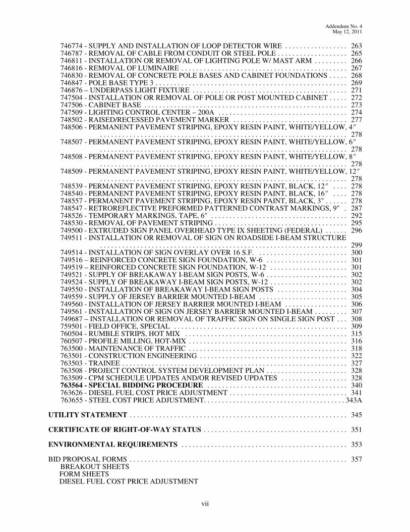
746774 - SUPPLY AND INSTALLATION OF LOOP DETECTOR WIRE . . . . . . . . . . . . . . . . . 263746787 - REMOVAL OF CABLE FROM CONDUIT OR STEEL POLE . . . . . . . . . . . . . . . . . . . 265746811 - INSTALLATION OR REMOVAL OF LIGHTING POLE W/ MAST ARM . . . . . . . . . 266746816 - REMOVAL OF LUMINAIRE . . . . . . . . . . . . . . . . . . . . . . . . . . . . . . . . . . . . . . . . . . . . . 267746830 - REMOVAL OF CONCRETE POLE BASES AND CABINET FOUNDATIONS . . . . . 268746847 - POLE BASE TYPE 3 . . . . . . . . . . . . . . . . . . . . . . . . . . . . . . . . . . . . . . . . . . . . . . . . . . . . 269746876 – UNDERPASS LIGHT FIXTURE . . . . . . . . . . . . . . . . . . . . . . . . . . . . . . . . . . . . . . . . . . 271747504 - INSTALLATION OR REMOVAL OF POLE OR POST MOUNTED CABINET . . . . . 272747506 - CABINET BASE . . . . . . . . . . . . . . . . . . . . . . . . . . . . . . . . . . . . . . . . . . . . . . . . . . . . . . . 273747509 - LIGHTING CONTROL CENTER – 200A . . . . . . . . . . . . . . . . . . . . . . . . . . . . . . . . . . . 274748502 - RAISED/RECESSED PAVEMENT MARKER . . . . . . . . . . . . . . . . . . . . . . . . . . . . . . . 277748506 - PERMANENT PAVEMENT STRIPING, EPOXY RESIN PAINT, WHITE/YELLOW, 4O
. . . . . . . . . . . . . . . . . . . . . . . . . . . . . . . . . . . . . . . . . . . . . . . . . . . . . . . . . . . . . . . . . . . 278748507 - PERMANENT PAVEMENT STRIPING, EPOXY RESIN PAINT, WHITE/YELLOW, 6O
. . . . . . . . . . . . . . . . . . . . . . . . . . . . . . . . . . . . . . . . . . . . . . . . . . . . . . . . . . . . . . . . . . . 278748508 - PERMANENT PAVEMENT STRIPING, EPOXY RESIN PAINT, WHITE/YELLOW, 8O
. . . . . . . . . . . . . . . . . . . . . . . . . . . . . . . . . . . . . . . . . . . . . . . . . . . . . . . . . . . . . . . . . . . 278748509 - PERMANENT PAVEMENT STRIPING, EPOXY RESIN PAINT, WHITE/YELLOW, 12O
. . . . . . . . . . . . . . . . . . . . . . . . . . . . . . . . . . . . . . . . . . . . . . . . . . . . . . . . . . . . . . . . . . . 278748539 - PERMANENT PAVEMENT STRIPING, EPOXY RESIN PAINT, BLACK, 12O . . . . 278748540 - PERMANENT PAVEMENT STRIPING, EPOXY RESIN PAINT, BLACK, 16O . . . . 278748557 - PERMANENT PAVEMENT STRIPING, EPOXY RESIN PAINT, BLACK, 3" . . . . . . 278748547 - RETROREFLECTIVE PREFORMED PATTERNED CONTRAST MARKINGS, 9" . 287748526 - TEMPORARY MARKINGS, TAPE, 6" . . . . . . . . . . . . . . . . . . . . . . . . . . . . . . . . . . . . . 292748530 - REMOVAL OF PAVEMENT STRIPING . . . . . . . . . . . . . . . . . . . . . . . . . . . . . . . . . . . . 295749500 - EXTRUDED SIGN PANEL OVERHEAD TYPE IX SHEETING (FEDERAL) . . . . . . 296749511 - INSTALLATION OR REMOVAL OF SIGN ON ROADSIDE I-BEAM STRUCTURE
. . . . . . . . . . . . . . . . . . . . . . . . . . . . . . . . . . . . . . . . . . . . . . . . . . . . . . . . . . . . . . . . . . . 299749514 - INSTALLATION OF SIGN OVERLAY OVER 16 S.F. . . . . . . . . . . . . . . . . . . . . . . . . 300749516 – REINFORCED CONCRETE SIGN FOUNDATION, W-6 . . . . . . . . . . . . . . . . . . . . . . 301749519 – REINFORCED CONCRETE SIGN FOUNDATION, W-12 . . . . . . . . . . . . . . . . . . . . . 301749521 - SUPPLY OF BREAKAWAY I-BEAM SIGN POSTS, W-6 . . . . . . . . . . . . . . . . . . . . . . 302749524 - SUPPLY OF BREAKAWAY I-BEAM SIGN POSTS, W-12 . . . . . . . . . . . . . . . . . . . . . 302749550 - INSTALLATION OF BREAKAWAY I-BEAM SIGN POSTS . . . . . . . . . . . . . . . . . . . 304749559 - SUPPLY OF JERSEY BARRIER MOUNTED I-BEAM . . . . . . . . . . . . . . . . . . . . . . . . 305749560 - INSTALLATION OF JERSEY BARRIER MOUNTED I-BEAM . . . . . . . . . . . . . . . . . 306749561 - INSTALLATION OF SIGN ON JERSEY BARRIER MOUNTED I-BEAM . . . . . . . . . 307749687 – INSTALLATION OR REMOVAL OF TRAFFIC SIGN ON SINGLE SIGN POST . . . 308759501 - FIELD OFFICE, SPECIAL . . . . . . . . . . . . . . . . . . . . . . . . . . . . . . . . . . . . . . . . . . . . . . . 309760504 - RUMBLE STRIPS, HOT MIX . . . . . . . . . . . . . . . . . . . . . . . . . . . . . . . . . . . . . . . . . . . . 315760507 - PROFILE MILLING, HOT-MIX . . . . . . . . . . . . . . . . . . . . . . . . . . . . . . . . . . . . . . . . . . . 316763500 - MAINTENANCE OF TRAFFIC . . . . . . . . . . . . . . . . . . . . . . . . . . . . . . . . . . . . . . . . . . . 318763501 - CONSTRUCTION ENGINEERING . . . . . . . . . . . . . . . . . . . . . . . . . . . . . . . . . . . . . . . . 322763503 - TRAINEE . . . . . . . . . . . . . . . . . . . . . . . . . . . . . . . . . . . . . . . . . . . . . . . . . . . . . . . . . . . . . 327763508 - PROJECT CONTROL SYSTEM DEVELOPMENT PLAN . . . . . . . . . . . . . . . . . . . . . . 328763509 - CPM SCHEDULE UPDATES AND/OR REVISED UPDATES . . . . . . . . . . . . . . . . . . 328763564 - SPECIAL BIDDING PROCEDURE . . . . . . . . . . . . . . . . . . . . . . . . . . . . . . . . . . . . . . 340763626 - DIESEL FUEL COST PRICE ADJUSTMENT . . . . . . . . . . . . . . . . . . . . . . . . . . . . . . . . 341
763655 - STEEL COST PRICE ADJUSTMENT. . . . . . . . . . . . . . . . . . . . . . . . . . . . . . . . . . . . . . . 343A
UTILITY STATEMENT . . . . . . . . . . . . . . . . . . . . . . . . . . . . . . . . . . . . . . . . . . . . . . . . . . . . . . . . . . . 345
CERTIFICATE OF RIGHT-OF-WAY STATUS . . . . . . . . . . . . . . . . . . . . . . . . . . . . . . . . . . . . . . . 351
ENVIRONMENTAL REQUIREMENTS . . . . . . . . . . . . . . . . . . . . . . . . . . . . . . . . . . . . . . . . . . . . . 353
BID PROPOSAL FORMS . . . . . . . . . . . . . . . . . . . . . . . . . . . . . . . . . . . . . . . . . . . . . . . . . . . . . . . . . . . 357BREAKOUT SHEETS
FORM SHEETS DIESEL FUEL COST PRICE ADJUSTMENT
vii

Addendum No. 4May 12, 2011
Contract No. T200809003.01
CERTIFICATION
BID BOND
viii

Addendum No. 4May 12, 2011
Contract No. T200809003.01
GENERAL NOTICES
CONTRACT LIQUIDATED DAMAGES
The contract drawings and notes provide a sequence of construction for this contract.
FAILURE TO OPEN PROJECT TO UNRESTRICTED HIGHWAY TRAFFIC ON TIME
The total number of calendar days proposed by the bidder shall become the contract time for this project andshall be the basis for the determination of any contract time related adjustments to the contract.
Road User Costs of $35,000.00/calendar day have been established for this project.
Interim Road User costs for delays in opening lanes along both SR1 and I95 will be enforced according tothe below charts:
Northbound I-95
Contractor Penalties for Failure to Reopen Lanes
Time All Lanes Reopened(“Verizon” time)
One Lane Closure Two Lane ClosureThree Lane Closure / Full Closure with Detour
5:00 AM to 5:14 AM No Penalty No Penalty No Penalty5:15 AM to 5:29 AM $2,000 $2,000 $2,0005:30 AM to 5:44 AM $2,500 $2,500 $3,0005:45 AM to 5:59 AM $3,000 $3,000 $4,0006:00 AM to 6:14 AM $4,000 $5,000 $5,0006:15 AM to 6:29 AM $5,000 $8,000 $12,0006:30 AM to 6:44 AM $6,000 $10,000 $18,0006:45 AM to 6:59 AM $8,000 $15,000 $25,000Not Open by 7:00 AM $10,000 $20,000 $35,000
For every hour, or portion thereof, after 7:00 AM, $5,000 will be assessed up to a Day Total of $80,000.
Southbound I-95
Contractor Penalties for Failure to Reopen Lanes
Time All Lanes Reopened(“Verizon” time)
One Lane Closure Two Lane ClosureThree Lane Closure / Full Closure with Detour
5:00 AM to 5:14 AM No Penalty No Penalty No Penalty5:15 AM to 5:29 AM No Penalty $1,000 $2,0005:30 AM to 5:44 AM No Penalty $1,250 $2,5005:45 AM to 5:59 AM No Penalty $1,500 $3,0006:00 AM to 6:14 AM No Penalty $2,000 $4,0006:15 AM to 6:29 AM No Penalty $2,500 $5,0006:30 AM to 6:44 AM No Penalty $3,000 $6,0006:45 AM to 6:59 AM No Penalty $4,000 $8,000Not Open by 7:00 AM $5,000 $5,000 $10,000
For every hour, or portion thereof, after 7:00 AM, $2,000 will be assessed up to a Day Total of $35,000.
1
Addendum No. 4May 12, 2011
Contract No. T200809003.01
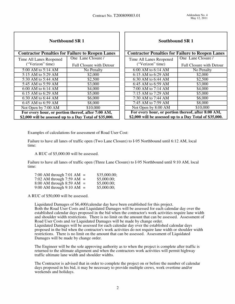
Northbound SR 1
Contractor Penalties for Failure to Reopen Lanes
Time All Lanes Reopened(“Verizon” time)
One Lane Closure /
Full Closure with Detour5:00 AM to 5:14 AM No Penalty5:15 AM to 5:29 AM $2,0005:30 AM to 5:44 AM $2,5005:45 AM to 5:59 AM $3,0006:00 AM to 6:14 AM $4,0006:15 AM to 6:29 AM $5,0006:30 AM to 6:44 AM $6,000
6:45 AM to 6:59 AM $8,000
Not Open by 7:00 AM $10,000For every hour, or portion thereof, after 7:00 AM,
$2,000 will be assessed up to a Day Total of $35,000.
Southbound SR 1
Contractor Penalties for Failure to Reopen Lanes
Time All Lanes Reopened(“Verizon” time)
One Lane Closure /
Full Closure with Detour6:00 AM to 6:14 AM No Penalty6:15 AM to 6:29 AM $2,0006:30 AM to 6:44 AM $2,5006:45 AM to 6:59 AM $3,0007:00 AM to 7:14 AM $4,0007:15 AM to 7:29 AM $5,0007:30 AM to 7:44 AM $6,0007:45 AM to 7:59 AM $8,000Not Open by 8:00 AM $10,000
For every hour, or portion thereof, after 8:00 AM,
$2,000 will be assessed up to a Day Total of $35,000.
Examples of calculations for assessment of Road User Cost:
Failure to have all lanes of traffic open (Two Lane Closure) to I-95 Northbound until 6:12 AM, localtime:
A RUC of $5,000.00 will be assessed.
Failure to have all lanes of traffic open (Three Lane Closure) to I-95 Northbound until 9:10 AM, localtime:
7:00 AM through 7:01 AM = $35,000.00;7:02 AM through 7:59 AM = $5,000.00;8:00 AM through 8:59 AM = $5,000.00;9:00 AM through 9:10 AM = $5,000.00;
A RUC of $50,000 will be assessed.
Liquidated Damages of $6,400/calendar day have been established for this project. Both the Road User Costs and Liquidated Damages will be assessed for each calendar day over theestablished calendar days proposed in the bid when the contractor's work activities require lane widthand shoulder width restrictions. There is no limit on the amount that can be assessed. Assessment ofRoad User Costs and /or Liquidated Damages will be made by change order.Liquidated Damages will be assessed for each calendar day over the established calendar daysproposed in the bid when the contractor's work activities do not require lane width or shoulder widthrestrictions. There is no limit on the amount that can be assessed. Assessment of LiquidatedDamages will be made by change order.
The Engineer will be the sole approving authority as to when the project is complete after traffic isreturned to the ultimate alignment and when the contractors work activities will permit highwaytraffic ultimate lane width and shoulder widths.
The Contractor is advised that in order to complete the project on or before the number of calendardays proposed in his bid, it may be necessary to provide multiple crews, work overtime and/orweekends and holidays.
2
Addendum No. 4May 12, 2011
Contract No. T200809003.01
CONSTRUCTION PHASING
If the contractor desires to revise the construction phasing presented in the contract documents inorder to affect the project's completion schedule and base their calendar days on this revision, thecontractor must submit an official revised construction phasing plan for the Department's review no laterthan forty - two (42) calendar days prior to the bid opening. The Department will review the contractor'srevised phasing and respond on whether this phasing is acceptable within fourteen (14) calendar days.During this time the Department will determine whether the Contractor's revised proposals for theconstruction phasing conforms to the project requirements.
After receiving the Department's comments, the contractor has the option to schedule a one-on-onereview meeting with the Department within seven (7) calendar days to discuss their proposal and theDepartment's comments. At that review meeting, documented by a court reporter, all comments anddiscussion will be held confidential. During the bidding process, all potential ideas presented by theContractor will be kept confidential. The contractor's revised phasing plan should show in detail thefollowing (but not limited to):
• All appropriate schedule information in order for the Department to make a determination ofwhether the revised phasing plan is viable.
• A written statement that no additional environmental impacts are incurred due to the phasingchanges.
2A

Addendum No. 4May 12, 2011
Contract No. T200809003.01
THIS PAGE IS INTENTIONALLY LEFT BLANK.

Contract No. T200809003.01 Addendum No. 4
May 12, 2011
following:
1. All pertinent provisions and requirements of the prime contract.2. Description of the work to be performed by the DBE subcontractor.3. The dollar value of each item of work to be completed by the DBE subcontractor and the
bid price of each item of work to be completed by the DBE subcontractor.
* * * * *CRITICAL DBE REQUIREMENTS
A bid may be held to be non-responsive and not considered if the required DBE information is notprovided. In addition, the bidder may lose its bidding capability on Department projects and such othersanctions as the Department may impose. It is critical that the bidder understands:
1. In the event that the bidder cannot meet the DBE goal as set forth in this specification, he/sheshall at the time of bid submit to the Department that percentage of the DBE Goal that will be met, ifany, on the written and notarized assurance made a part of this contract. The contractor shall also at thetime of bid submit all documentation that the contractor wishes to have the Department consider indetermining that the contractor made a Good Faith Effort to meet contract DBE Goals. The Departmentwill not accept Good Faith Effort documentation other than on the scheduled date and time of the bidopening. However, the Department may ask for clarification of information submitted should the needarise.
2. A bid which does not contain either a completely executed DBE Program Assurance and/orGood Faith Effort documentation, where appropriate, shall be declared non-responsive and shall not beconsidered by the Department.
3. Bidders shall submit with their bid the name, address, age of the firm, and the gross annualreceipts of each DBE and non-DBE subcontractor that supplied a quote or a bid to the prime on thisproject. The Department has attached this document following the Certification document at the end ofthe Proposal. Failure to submit this information will result in the bid being declared non-responsive andwill be rejected.
4. Failure of the apparent low bidder to present originals of all DBE subcontracts tosubstantiate the volume of work to be performed by DBE's as indicated in the bid within ten (10)calendar days after the bid opening shall create a non-rebuttable presumption that the bid is notresponsive.
5. Bidders are advised that failure to meet DBE Goals during the term of the contract maysubject them to Department sanctions as identified in the DBE Program Plan.
6. In the execution of this contract, the successful bidder agrees to comply with the followingcontract clauses:
Prompt Payment: The prime contractor/consultant receiving payments shall, within 30 days of receiptof any payment, file a statement with the Department on a form to be determined by the Department thatall subcontractors furnishing labor or material have been paid the full sum due them at the stage of thecontract, except any funds withheld under the terms of the contract as required by Chapter 8, Title 17of the Delaware Code, annotated and as amended. Any delay or postponement of payment from theabove referenced time frame may occur only for good cause following written approval of DelDOT. This clause applies to both DBE and non-DBE subcontractors.
Retainage: The prime contractor agrees to return retainage to each subcontractor within 15 calendar daysafter the subcontractor's work is satisfactorily completed. Any delay or postponement of payment fromthe above referenced time frame may occur only for good cause following written approval of DelDOT. This clause covers both DBE and non-DBE subcontractors. As guidance, once a subcontractor hassatisfactorily completed the physical work, and has given to the prime contractor a certified statementthat all laborers, lower tier contractors, and materialmen who have furnished labor and materials to thesubcontractor have been paid all monies due them, the prime contractor shall return retainage to thesubcontractor within 15 calendar days.
7. In the execution of this contract, the successful bidder agrees to comply with the following contract
13

Addendum No. 4
May 12, 2011Contract No. T200809003.01
STATE OF DELAWARE PREVAILING WAGES
PREVAILING WAGE DETERMINATION - Highway Construction
Delaware Department of Labor
Division of Industrial Affairs
Office of Labor Law Enforcement
Phone: 302 451-3423
Mailing Address:
225 Corporate Boulevard
Suite 104
Newark, DE 19702
Located at:
225 Corporate Boulevard
Suite 104
Newark, DE 19702
Prevailing Wages for HIGHWAY CONSTRUCTION Effective March 15, 2011
Classification New Cast le
County
Kent County Sussex County
Bricklayers $44.98 $44.98 $14.51
Carpenters $40.86 $48.31 $38.62
Cement Finishers $28.11 $24.68 $23.29
Electrical Line Workers $22.50 $54.05 $54.05
Electricians $57.10 $57.10 $57.10
Iron workers $42.20 $22.98 $25.35
Laborers $25.44 $23.33 $24.00
Millwrights $16.11 $15.63 $13.49
Painters $41.42 $41.42 $41.42
Piledrivers $59.23 $23.75 $26.95
Power Equip. Operators $31.46 $26.00 $26.31
Sheetmetal Workers $22.75 $20.31 $18.40
Truck Drivers $26.54 $21.68 $19.96
CERTIFIED: May 5, 2011 BY: Signature on file
ANTHONY J DELUCA, ADMINISTRATOR
LABOR LAW ENFORCEMENT SECTION
NOTICE TO CONTRACTORS
1. These rates are promulgated and enforced pursuant to the Prevailing Wage Regulations adopted by
the Department of Labor on April 3, 1992.
2. Classifications of workers are determined by the Department of Labor. For assistance in classifying
workers, or for a copy of the regulations or classifications, phone (302)451-3423.
3. Nonregistered apprentices must be paid the mechanic's rate.
33
Contract No. T200809003.01 Addendum No. 4
May 12, 2011
89A
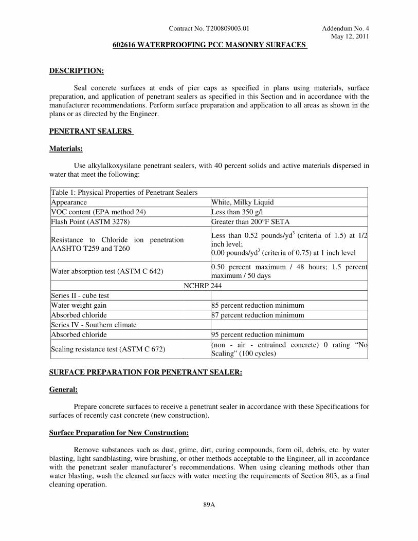
602616 WATERPROOFING PCC MASONRY SURFACES
DESCRIPTION:
Seal concrete surfaces at ends of pier caps as specified in plans using materials, surface
preparation, and application of penetrant sealers as specified in this Section and in accordance with the
manufacturer recommendations. Perform surface preparation and application to all areas as shown in the
plans or as directed by the Engineer.
PENETRANT SEALERS
Materials:
Use alkylalkoxysilane penetrant sealers, with 40 percent solids and active materials dispersed in
water that meet the following:
Table 1: Physical Properties of Penetrant Sealers
Appearance White, Milky Liquid
VOC content (EPA method 24) Less than 350 g/l
Flash Point (ASTM 3278) Greater than 200°F SETA
Resistance to Chloride ion penetration
AASHTO T259 and T260
Less than 0.52 pounds/yd
3 (criteria of 1.5) at 1/2
inch level;
0.00 pounds/yd3 (criteria of 0.75) at 1 inch level
Water absorption test (ASTM C 642) 0.50 percent maximum / 48 hours; 1.5 percent
maximum / 50 days
NCHRP 244
Series II - cube test
Water weight gain 85 percent reduction minimum
Absorbed chloride 87 percent reduction minimum
Series IV - Southern climate
Absorbed chloride 95 percent reduction minimum
Scaling resistance test (ASTM C 672) (non - air - entrained concrete) 0 rating “No
Scaling” (100 cycles)
SURFACE PREPARATION FOR PENETRANT SEALER:
General:
Prepare concrete surfaces to receive a penetrant sealer in accordance with these Specifications for
surfaces of recently cast concrete (new construction).
Surface Preparation for New Construction:
Remove substances such as dust, grime, dirt, curing compounds, form oil, debris, etc. by water
blasting, light sandblasting, wire brushing, or other methods acceptable to the Engineer, all in accordance
with the penetrant sealer manufacturer’s recommendations. When using cleaning methods other than
water blasting, wash the cleaned surfaces with water meeting the requirements of Section 803, as a final
cleaning operation.
Contract No. T200809003.01 Addendum No. 4
May 12, 2011
89B
Water for Blasting:
Use water meeting the requirements of Section 803.
Concrete Surface Cleaning Operation:
During the cleaning operation, exercise sufficient care to minimize the removal of the concrete
matrix. Furnish hand tools, power grinders, and other similar equipment to remove materials which
cannot be removed by water blasting without abrading the concrete matrix beyond acceptable limits.
Wash concrete surfaces cleaned by methods other than water blasting with water blasting equipment as
the final cleaning operation.
Limit the duration of water blasting to provide a light abraded surface. Do not allow surface abrasion to
exceed 0.016 inch. The Engineer will not require further cleaning of stains still apparent after abrading to
a depth of 0.016 inch. Avoid exposure of coarse aggregate by water blasting.
Reclean concrete surfaces which become contaminated before applying the penetrant sealer at no expense
to the Department prior to applying the penetrant sealer.
Application of Penetrant Sealer Materials:
Apply the penetrant sealer only to surfaces which have been prepared in accordance with these
Specifications and approved by the Engineer. For application of the penetrant sealer, meet these
Specifications and the penetrant sealer manufacturer’s recommendations.
Prior to application of any penetrant sealer, cure concrete for a minimum of 21 days.
Apply penetrant sealer no later than ten days after completion of the surface preparation and prior to any
contamination of the prepared surfaces as determined by the Engineer.
Application Equipment:
Apply the penetrant sealer using any suitable air or airless sprayer with an operating pressure of
approximately 20 psi.
Application Limitations:
Apply the penetrant sealer material only when the ambient air temperature is between 50 and
90ºF. Apply the penetrant sealer only to concrete surfaces which have dried a minimum of 48 hours after
water last contacted the concrete surfaces. Do not apply the penetrant sealer when winds are blowing 25
mph or more, during rainfall, or when water spray or mist is present.
Application:
Apply the penetrant sealer only to concrete surfaces that have been prepared in accordance with
the requirements and limitations set forth in these Specifications. Determine the actual coverage rate in
square feet per gallon on the basis of field trials. Conduct a field trial to determine coverage rate at the
beginning of any penetrant sealer application operation. For each field trial, determine the optimum
coverage rate for 50 ft2 of surface area. Maintain the penetrant sealer application rate between 155 and
225 ft2 covered per gallon of penetrant sealer used. Apply the penetrant sealer in a uniform manner
without puddling and skips. Redistribute any penetrant sealer which is applied and subsequently puddles
in low areas over the concrete surfaces by use of a squeegee. Generally, begin the application of the
penetrant at the lowest elevation and proceed upward toward higher elevations.

Contract No. T200809003.01 Addendum No. 4
May 12, 2011
89C
Maintain operating pressures in the sprayers used for application of the penetrant sealer material
sufficiently low so that atomization or misting of the material does not occur.
CONTROL OF MATERIALS:
Packaging and Identification:
Deliver the penetrant sealer to the project in unopened, sealed containers with the manufacturer’s
label identifying the product and with numbered seals intact. Ensure that each container is clearly marked
by the manufacturer with the following information:
a. Manufacturer’s name and address.
b. Product name.
c. Date of manufacture.
d. Expiration date.
e. LOT identification number.
f. Container serial number.
Manufacturer’s Certification:
Provide the Engineer a certification from the manufacturer, confirming that the penetrant sealer
meets the requirements of this Section. Do not incorporate these materials into the project until the
Engineer has accepted and approved the certification for the material. Submit such certification for each
LOT of material delivered to the project. In each certification, identify the serial or LOT numbers of the
containers certified.
Materials Sampling for Tests:
The Engineer may require samples from each LOT or container of materials delivered to the
project or from containers at the point of use. When samples are required, furnish samples in accordance
with the Engineer’s instructions.
Storage of Materials:
Store materials delivered to the job site in original unopened containers within an appropriate
storage facility. Use a storage facility that provides protection from the elements, and safe and secure
storage of the materials.
Unused Material in Opened Containers:
Do not return unused material in opened containers to storage for later use. Either apply such
material to appropriate areas on concrete surfaces or remove and dispose of it at offsite locations provided
by the Contractor.
Acceptance:
The Engineer will accept penetrant sealer application when it is determined that the Contractor
has properly cleaned all surface areas to be sealed and has applied the penetrant sealer within the required
rates of application.

Contract No. T200809003.01 Addendum No. 4
May 12, 2011
89D
MEASUREMENT AND PAYMENT
The preparation, cleaning, testing, certifications, field trials, furnishing, and applying of the
concrete sealer on the various ends of pier caps will not be measured but the cost will be incidental to the
pertinent “Portland Cement Concrete Masonry” item. The payment will be full compensation for all
material, labor, equipment, tools, and incidentals necessary to complete the work.
3/11/11

Addendum No. 4
May 12, 2011Contract No. T200809003.01
602772 - MECHANICALLY STABILIZED EARTH WALLS
Description:
This work shall consist of the design and construction of mechanically stabilized earth (M.S.E.)
retaining walls in accordance with the AASHTO definitions of mechanically stabilized earth walls employing
tensile reinforcements in the soil mass. The M.S.E. retaining wall shall be constructed in conformance with
these specifications and to the lines, grades, and dimensions shown on the Plans or as established by the
Engineer. Design details for these structures shall be as submitted for approval.
The M.S.E. retaining wall shall be designed in conformance with the 2007 AASHTO LRFD Bridge
Design Specifications, 4th Edition including all current Interims and the requirements specified on the Plans.
The following additional specific design requirements shall be met by the developed plans:
a. All retaining wall components shall be designed for a minimum service life of 100 years.
b. Completed walls shall have a concrete facing with a finish or aesthetic treatment as approved
by the Engineer.
Design Requirements:
The design of the internal stability of the MSE wall shall be the responsibility of the wall
manufacturer. Design constraints imposed by external (overall) stability, such as allowable bearing pressure
due to the combined effects of vertical and lateral loads, minimum length of reinforcing elements, as set forth
herein, shall be the responsibility of the Contractor.
Working drawings bearing the fabricator’s or supplier’s title block and design calculations sealed by
a professional engineer registered in the State of Delaware shall be submitted for review and approval by the
Engineer at least 4 weeks before work is to begin. Working drawings and design calculations shall include
the following:
(a) Existing ground elevations that have been verified by the Contractor for each location
involving construction wholly or partially in original ground.
(b) Layout of wall that will effectively retain the earth but not less in height or length than that
shown for the wall system in the Plans.
(c) Complete design calculations substantiating that the proposed design satisfies the design
parameters in the Plans and in the special provisions.
(d) Complete details of all elements required for the proper construction of the system, including
complete material specifications.
No work or ordering of materials shall commence until approval of the working drawings has been
given by the Engineer. Acceptance of the Contractor’s working drawings shall not relieve the Contractor of
his responsibility under the contract for the successful completion of the work. All work pertaining to
Working Drawings for MSE retaining walls shall be done at no additional cost to the Department.
Internal Stability: The internal stability of a mechanically stabilized earth structure shall be the
responsibility of the wall supplier. Internal stability issues include, but are not limited to, pullout (or
92

Addendum No. 4
May 12, 2011Contract No. T200809003.01
geotechnical) failure of the soil reinforcing elements, tensile failure of the soil reinforcing elements, failure
of panel/reinforcement connections, failure through the backfill material within the reinforced mass, and
failure along a reinforcing element surface within the reinforced soil mass.
Sliding, overturning, and bearing capacity shall be evaluated by the wall supplier. The allowable
bearing capacity at the MSE walls shall be determined by the Contractor and submitted for approval by the
Engineer.
Failure Plane: The so-called failure plane shall be taken as coincident with the locus of the points
of maximum tensile force which separates the reinforced mass into an active zone between the face of the
wall and the line of maximum tensile forces, and a resistant zone behind the maximum tensile forces line.
The location of the so-called failure plane shall be adjusted, where necessary, to account for the effects of
significant externally applied loads, such as those due to a bridge abutment footing supported directly on the
mechanically stabilized backfill.
Resistance Factors for Permanent MSE Walls:
0.9 for pullout of tensile reinforcing elements.
1.0 for sliding of the reinforced soil mass along the interface between the reinforced mass and the
underlying native soil. The passive resistance of the soil in front of the embedded portion of the wall shall
not be included in evaluating lateral stability of the reinforced mass.
0.75 for failure at the facing panel/reinforcing element connection based on the maximum allowable
reinforcement tension at the end of the design service life.
Panel/Reinforcement Connections: All connections shall be positive structural connections subject
to the galvanizing and metal loss rates, for metal reinforcing elements, and allowable tensile stresses given
in Stresses in Reinforcing Elements. The structural adequacy and pullout capacity of the connections shall
be demonstrated by test data from pullout and flexural tests on full size panels in which all connections are
loaded simultaneously. The test data shall be provided by the manufacturer.
Drainage: Drainage shall be as designed by the Contractor or as directed by the Engineer. Internal
and external drainage shall be evaluated for all structures to prevent saturation of the backfill or to intercept
any surface flows containing aggressive elements such as de-icing salts. Internal drainage of the mechanically
stabilized backfill shall be considered where the anticipated rate of surface infiltration due to precipitation
exceeds the vertical permeability of the backfill material.
Length of Reinforcing Elements: The length of the reinforcing elements shall be constant over the
entire height of any wall section. The minimum reinforcement length shall be as shown on the Plans and not
less than eight (8) feet in accordance with AASHTO. In addition, the length of the reinforcing elements shall
be sufficient to satisfy all the design criteria with respect to both internal and external stability.
Stresses in Reinforcing Elements: The reinforcing elements shall be designed to have a minimum
design life of 100 years with all material and other resistance factors intact at the end of the design life of the
mechanically stabilized earth structure.
Unless otherwise indicated by the Engineer, the following metal loss rates shall be used in
determining the useful area of metal soil reinforcement remaining at the end of the nominal service life:
Loss of Galvanizing (first 2 years): 0.58 mil./year
Loss of Galvanizing (2 years - depletion): 0.16 mil./year
93
Addendum No. 4
May 12, 2011Contract No. T200809003.01
Carbon steel (after zinc depletion): 0.47 mil./year
The allowable tensile stress in the longitudinal wires of the mesh reinforcing elements shall not
exceed fifty-five (55) percent of the nominal yield stress of the steel, provided that the yield stress does not
exceed 65 kips/sq.in. The maximum tension in any reinforcing element shall not exceed the product of the
maximum allowable tensile stress and the area of steel remaining at the end of the nominal service life.
Stresses at Panel/Reinforcement Connections. The horizontal earth pressure used to design the
connections and facing panels shall be equal to the maximum horizontal stress computed at each
reinforcement level, but in no case shall it be less than eighty-five (85) percent of the maximum horizontal
pressure. In the case of rigid panel/reinforcement connections the allowable stress in the reinforcement at
the connection shall be reduced to allow for bending stresses induced in the connection due to relative vertical
movement between the facing panels and the reinforced backfill.
Internal Horizontal Stresses: For MSE wall systems with quasi-inextensible reinforcing elements,
the horizontal stress at each reinforcement level shall be computed by multiplying the corresponding vertical
stress by an earth pressure coefficient, K. The vertical stress shall be computed using a layer-by-layer
approach following Meyerhof=s analysis for eccentrically loaded footings; i.e., the resulting vertical stress at
any reinforcement level is a function of the vertical stress due to the self weight of the overlying backfill
material and the increase in vertical stress due to the overturning effects of the lateral load from the random
fill retained by the mass of reinforced backfill.
The value of the earth pressure coefficient, K, shall be assumed equal to the at-rest (Ko) value at the
top of the wall decreasing linearly to the Rankine active value (Ka) at a depth of 20 feet. At depths in excess
of 20 feet, the value of K shall be taken as Ka. For normally consolidated soils, Ko =1-sinn, where n is the
angle of shearing resistance of the backfill material. For typical values of n, Ko may be assumed equal to
1.5Ka.
Pullout Resistance (Anchorage) Factors: Non-dimensional anchorage factors (denoted as Ac) as
determined by laboratory or field pullout tests on reinforcing elements shall be based on the interpreted failure
load at a maximum displacement of three-quarters (3/4) of an inch. The anchorage factor, Ac, shall be
computed from the expression
Ac = Load at 3/4-inch displacement
pvdbN
where pv = vertical stress (due to self weight of backfill only) at the reinforcement level, d = diameter of
transverse wires, b = width of transverse wires for a 6-inch spacing of longitudinal wires, N = number of
transverse wires.
The spacing between transverse wires shall not be less than six (6) inches. The non-dimensional
anchorage factor shall be assumed to decrease linearly from 40 at the top of the wall to 15 at a depth of 20
feet. At depths greater than 20 feet the anchorage factor shall be taken equal to 15.
Architectural Treatment
All walls shall have the same shape and sized panels except as necessary to maintain grade and length. All
panels shall have a cruciform shape with each panel nominal size (out-to-out of cruciform) of approximately
5' by 5'. The color of the concrete panels shall match the adjacent concrete structures.
A pilaster made of individual panels, approximately 5' high x 4' wide, shall be placed at each abutment corner
and then at equal intervals along the wall (approximately 90' intervals). The abutment corner shall split the
94
Addendum No. 4
May 12, 2011Contract No. T200809003.01
panel evenly. The pilaster panel shall be flush with the remaining wall.
All panels shall have a smooth float finish in accordance with Section 602.17.d. The contractor shall submit
sample drawings of a typical wall elevation along with details of the typical and pilaster panel and may be
required to produce a sample panels before panel fabrication can begin.
Materials:
The Contractor shall make arrangements to purchase or manufacture the concrete facing panels,
reinforcing mesh or strips, attachment devices, and all other necessary components. Materials not conforming
to this section of the specifications shall not be used without written consent from the Engineer.
Steel Reinforcing Mesh. Reinforcing mesh shall be shop fabricated of cold drawn steel wire
conforming to the minimum requirements of A 82 and shall be welded into the finished mesh fabric in
accordance with A 185. Galvanization shall be applied after the mesh is fabricated and conform to the
minimum requirements of A 123.
Steel Reinforcing Strips. Reinforcing strips shall conform to the physical and mechanical properties
of ASTM A 572, Grade 65 steel. Galvanizing shall conform to the minimum requirements of AASHTO M111
(ASTM A 123).
Steel Connectors. Connectors shall be fabricated from cold drawn steel wire conforming to the minimum
requirements of A 82. Pins shall be fabricated from A 36 steel. Connectors and pins shall be galvanized to
conform to the minimum requirements of A 123.
Filter Fabric. Where required by design, filter fabric shall be placed behind the facing units. Filter
fabric shall be woven polypropylene fabric, meeting the requirements of M 288 for a Class I geotextile having
an Ultraviolet Stability of 70% strength retention after 500 hours as tested by D 4355. Slit film geotextile
shall not be allowed.
Backfill. Multiple types of backfill are required for the construction of the MSE walls. All backfill
material used in the structure volume shall be reasonably free from organic or otherwise deleterious materials
and shall be as specified on the plans. Placement limits are shown on the plans. The material requirements
for each backfill type are as follows:
Select Backfill. Select backfill shall conform to the following gradation limits as determined by AASHTO
T-27 (ASTM D-422):
Reinforced Backfill
Sieve Size Percent Passing
4 inches 100
No. 40 0-60
No. 200 0-15
In addition, the select backfill material shall conform to the following requirements:
a) Plasticity Index: The Plasticity Index (P.I.), as determined by AASHTO T- 90 (ASTM D-4318),
shall not exceed 6.
95

Addendum No. 4
May 12, 2011Contract No. T200809003.01
b) The material shall be substantially free of shale or other soft, poor durability particles. Testing in
accordance with AASHTO T-104 shall be performed to verify a magnesium sulfate soundness loss
of less than 30% after four cycles.
c) Electrochemical Requirements - The backfill materials shall meet the following criteria:
Requirements Test Methods
Resistivity >3,000 ohm-cm AASHTO T-288-91
pH 5-10 AASHTO T-289-91
Chlorides <100 parts per million AASHTO T-291-91
Sulfates <200 parts per million AASHTO T-290-91
Organic Content <1% AASHTO T-267-86
If the resistivity is greater or equal to 5000 ohm-cm, the chloride and sulfates requirements may be
waived.
DelDOT No. 57 Stone. Free draining stone conforming to DelDOT No. 57 stone or approved equal shall be
placed to an elevation as specified in the plans of the MSE embankment.
The Contractor shall furnish to the Engineer a Certificate of Compliance certifying that the backfill
materials comply with this section of the specifications prior to backfill placement. A copy of all test results
performed by the Contractor, which are necessary to assure compliance with the specifications, shall also be
furnished to the Engineer. Backfill not conforming to this specification shall not be used without the written
consent of both the Engineer and the wall supplier.
Concrete: Concrete for the facing, leveling pad, moment slab and barrier shall conform to the
requirements of Section 602 of the Specifications.
Construction Methods:
The selected MSE wall manufacturer shall provide a representative on site at the outset of the wall
construction and periodically throughout construction of the wall and at the direction of the Engineer. The
wall manufacturer’s representative shall be present at a pre-construction conference to provide an overview
of the wall system and a detailed construction procedure to the contractor and the Engineer.
Wall Excavation. Excavation shall be in accordance with the requirements of the general
specifications and in reasonably close conformity with the limits shown on the Plans. Temporary excavation
support as required shall be the responsibility of the Contractor. The base of the excavation shall be
completed to within +/- 3 inches of the staked elevations unless otherwise directed by the Engineer.
Foundation Preparation. The foundation for the structure shall be graded level for a width 1 foot
beyond the length of the reinforcement elements or as shown on the Plans. Prior to wall construction, the
foundation shall be proofrolled under the observation of the Engineer. Any unsuitable foundation material
as determined by the Engineer shall be excavated to the determined depth and replaced with Borrow Type
B and shall be compacted in accordance with Backfill Placement as described below.
At each panel foundation level, a precast reinforced or a cast-in-place unreinforced concrete leveling
pad of the type shown on the plans shall be provided. The leveling pad shall be cured a minimum of 12 hours
before placement of wall panels.
Wall Erection. The wall system components shall be constructed in accordance with the wall system
96
Addendum No. 4
May 12, 2011Contract No. T200809003.01
supplier's recommendations and construction manual. The wall shall be constructed vertical and within the
specified tolerances. The overall vertical tolerance of the wall and the horizontal alignment tolerance shall
not exceed 3/4-inch per 10 feet. Bulging in the vertical or horizontal direction shall be limited to 2 inches as
measured from the theoretical wall line. The Engineer shall be notified of any bulging areas that exceed this
limit.
Backfill Placement. Backfill placement shall closely follow erection of each course of concrete facing
units. Backfill shall be placed in such a manner as to avoid any damage or disturbance to the wall materials
or misalignment of the facing. Any wall materials that become damaged or disturbed during backfill
placement shall be removed and replaced at the Contractor's expense or corrected as directed by the Engineer.
The Engineer will be the sole authority as to the acceptability of any repairs to damaged wall materials. Any
misalignment or distortion of the wall elements due to placement of backfill outside the limits of this
specification shall be corrected as directed by the Engineer.
Backfill within the zone of soil reinforcements shall be compacted to 95% maximum dry density and
optimum moisture content, as determined by AASHTO T 99, by at least four (4) passes of a heavy roller
having a minimum dynamic force of 20 tons impact per vibration and a minimum frequency of 16 hertz.
The moisture content of the backfill material prior to and during compaction shall be uniformly
distributed throughout each layer. The water content of the wall backfill shall not deviate from the optimum
water content by more than 2%. Backfill material with a placement moisture content in excess of the optimum
moisture content shall be removed and reworked until the moisture content is uniformly acceptable
throughout the entire lift.
The maximum lift thickness after compaction shall not exceed 10 inches regardless of the vertical
spacing between layers of soil reinforcements. The Contractor shall decrease this lift thickness as required
to obtain the specified density.
Prior to placement of the soil reinforcements, the backfill elevation after compaction within the zone
of soil reinforcements shall be 2 inches above the connection elevation from a point approximately 24 inches
behind the facing to the free end of the soil reinforcements unless otherwise shown on the Plans.
Compaction within 3 feet of the facing shall be achieved by at least three (3) passes of a lightweight
mechanical tamper, roller or vibratory system. Care shall be exercised in the compaction process to avoid
misalignment of the facing. Heavy compaction equipment shall not be used to compact backfill within 3 feet
of the wall face. At the end of each day's operation, the Contractor shall slope the last level of backfill away
from the wall facing to direct runoff of rainwater away from the wall face. In addition, the Contractor shall
not allow surface runoff from adjacent areas to enter the wall construction site.
Leveling Pad. The concrete leveling pad at the concrete facing shall be unreinforced and constructed
to the elevation and width shown on the Plans. The leveling pad shall be constructed on compacted, drained
subgrade.
Utilities. The contractor shall accommodate the passage of utilities through the reinforced
embankment material. The soil reinforcements shall be placed to permit the installation and operation of, and
access to, the utilities constructed within the embankment while satisfying the design requirements of the
MSE wall. The MSE wall manufacturer shall provide a construction sequence for installation of utilities
within the reinforced embankment which does not jeopardize the integrity and stability of the reinforced soil
mass.
Moment Slab and Barrier. The moment slab and barrier shall be constructed according to the details
shown on the plans.
97
Addendum No. 4
May 12, 2011Contract No. T200809003.01
Toe protection. The toe of the wall shall be embedded in accordance with the Plans and shall be
protected as required for the life of the structure to avoid undermining the wall face.
Method of Measurement:
MSE Wall design and construction including all material, labor, equipment, expendables, etc.,
incidental to their installation and testing, will not be measured but will be paid for at the Contract lump sum
price for pertinent Retaining Wall or Abutment items. All excavations required for the construction of the
MSE Wall will not be measured and will be incidental to the construction of the pertinent Retaining Wall or
Abutment items. Temporary excavation support as required will not be measured and will be incidental to
the construction of the pertinent Retaining Wall or Abutment items. All backfill material behind the MSE
Wall which is not Type F borrow and as shown on the MSE Wall plans, will not be measured and will be
incidental to the construction of the pertinent Retaining Wall or Abutment items. Excavation of unsuitable
material will be paid for under Item 212000 undercut excavation and backfilling with Borrow Type B will
be paid for under Item 209002.
The concrete and reinforcement for the moment slab and barrier and coping will be measured
separately and will be paid for as a separate item. The concrete leveling pad is included in this pay item.
Basis of Payment:
The payment will be full compensation for all components of the MSE Wall and shall include full
compensation for designing, fabricating, furnishing, installing and for all materials, labor, tools, equipment,
and incidentals necessary to complete the installation in conformance with the plans and Specifications. In
the event that an increase or decrease in the area of the wall elevation is required, the increase or decrease in
the lump sum bid shall equal the increased or decreased area multiplied by the lump sum price divided by the
original elevation area. The “original elevation area” shall include the below-grade area of the concrete fascia.
Retaining Walls will not be measured but will be paid for at the Contract Lump Sum price for the
pertinent Retaining Wall or Abutment items.
NOTE:
A breakout sheet attached to the Proposal list the walls under this item. The Contractor shall fill in
a unit price for each item and the cost (unit price times the proposed quantity). The lump sum bid for Item
602772 - Mechanically Stabilized Earth Walls shall be the sum of the cost for all items listed. The breakout
sheet shall be attached to the Bid Proposal. Failure to submit the breakout sheet with the Bid Proposal will
result in the Bid Proposal being declared non-responsive and rejected.
The Department reserves the right to delete from the Contract one or more of the items listed and
right to add or subtract from the quantity of each item. The lump sum to be paid will be adjusted in
accordance with the Contractor’s unit prices as required above. There will be no extra compensation if such
additions and/or deletions are made.
4/2911
97A

Addendum No. 4
May 12, 2011Contract No. T200809003.01
602774 - MASONRY FOR LIGHT POLE FOUNDATION (CY)
Description:
This work shall consist of all labor, materials, equipment, and services necessary to perform all operations to
complete the installation of drilled shafts for light poles. The work shall be completed in accordance with the plans,
Delaware Department of Transportation’s Specifications for Road and Bridge Construction dated August 2001 (Standard
Specifications), and this Special Provision. The work involves installing constant-diameter drilled shafts through Coastal
Plain sediments and Piedmont Residuum. High water tables may be present.
Materials:
Materials shall meet the following requirements:
a. Portland Cement Concrete
Portland cement concrete shall be 4500-psi minimum (Class A) and shall meet the requirements specified in
Section 602 and 812, in the Delaware Department of Transportation’s Specifications for Road and Bridge
Construction (August 2001). Where not otherwise specified, ACI 336.1-94 shall be followed. Water used in
mixing concrete shall conform to Section 803 of the Standard Specifications.
Concrete shall remain workable and maintain a 4-inch slump for up to four hours after placing. If free fall
methods are utilized for placement, the maximum coarse aggregate size shall be reduced to 3/8-inch. A slump
value range of 5 ±1-inch shall be provided for all uncased holes and a slump range of 6 ±1.5-inch shall be
provided for cased holes. A minimum slump of 6-inch with the addition of a retarder is required when a casing
is being withdrawn. An acceptable water reducing and retarding admixture shall be added to the concrete to
produce the specified slump. Under no circumstances shall the admixture cause segregation of the concrete.
If any admixtures are added to the concrete at the site, the admixture must be added to the concrete by a
qualified Contractor-furnished technician. Immediately after the addition of the admixture, the drum shall be
turned a minimum of thirty revolutions, at mixing speed, until the concrete is thoroughly mixed. The technician
shall then test the slump and consistency of the concrete mixture. Under no circumstances shall the Contractor
add additional water to the concrete mixture to reach the desired slump.
b. Reinforcing Steel
Deformed reinforcing bars shall be in accordance with the sizes, spacing, dimensions, and details shown on the
plans and shall conform to AASHTO M31, Grade 60, and the requirements of Section 603 and 604 of the
Specifications.
c. Casing
Casing shall be metal, smooth, clean, watertight, and of ample strength to withstand both handling and driving
stresses and the pressure of both concrete and the surrounding earth materials. Thickness of the casings shall
not be less than 0.25-inch. The inside diameter of casing shall not be less than the specified size of the shaft.
No extra compensation will be allowed for concrete required to fill an oversized casing or oversized excavation.
All casings shall be removed from shaft excavations. Permanent steel casings shall not be used.
d. Slurry
Use of slurry shall not be permitted.
e. Ground Rod and Clamp
Ground rods shall be copper clad, approved by the Underwriter’s Laboratory, and be supplied with approved
clamps for connecting the grounding conductor to the rod. Ground rods shall be ¾ inch diameter by 10 foot,
sectional, unless otherwise specified on the Plans.
99

Addendum No. 4
May 12, 2011Contract No. T200809003.01
f. Conduit sweeps
Conduit sweeps shall meet the requirements for galvanized steel rigid conduit in Section 745 of the Delaware
Department of Transportation’s Specifications for Road and Bridge Construction (August 2001).
g. Anchor Bolts
Anchor bolts will be supplied by the same entity that supplies the poles. Anchor bolts shall have a minimum
yield strength of 55,000 psi.
Contractor Qualification:
This work shall be performed under the supervision of the Contractor's superintendent, who will be fully
knowledgeable and experienced, as defined herein, in the construction of drilled shaft foundations of similar sized shafts
and geotechnical conditions using both cased and slurry methods. Further, the Contractor and the Contractor's
superintendent performing the work shall document at least five years previous experience within the last eight years
constructing drilled shafts, with at least two years at the current firm. The Contractor's equipment shall have the capacity
to undertake the work and shall be sufficient to complete the work within the specified contract time.
The Contractor shall provide documentation of his qualifications, experience record, prior project references,
and the availability of the equipment needed to perform the required work. All prior project references shall be currently
available personnel who can verify the quality of the contractor’s previous work and shall include current name, address,
and telephone number. This documentation shall reference the experience of the drilled shaft Contractor and the drilled
shaft Contractor's superintendent in responsible charge of the drilled shaft operations. This documentation shall
reference successful construction of similar sized shafts in the following conditions:
a. Experience in successfully installing drilled shafts of the size shown in the plans. The minimum
experience shall consist of ten similar-sized projects in the past five years. Descriptions of projects
must include a point of contact with the owner that is familiar with the project.
b. Experience in cleaning shaft bottoms when working under wet conditions.
Equipment:
The Contractor shall furnish all equipment and instrumentation necessary for installation of the shafts.
The excavation and drilling equipment shall have adequate capacity including power, torque, and down thrust
to excavate a hole of the maximum diameter shown on the plans and to a depth of 15-feet or 20 percent beyond the
depths shown in the contract documents, whichever is greater.
The excavation and tools shall be of adequate design, size, and strength to perform the work shown in the
contract documents or described herein. When the material encountered cannot be drilled using conventional earth
augers with soil or rock teeth, drilling buckets, and/or over-reaming tools, the Contractor shall provide special drilling
equipment including but not limited to: rock core barrels, rock tools, air tools, blasting materials, and other equipment
as necessary to construct the shaft excavation to the size and depth required.
Provide a descriptive listing of available equipment that is fully capable of cleaning shaft bottoms when shafts
are excavated under wet conditions.
Site Information:
Test Boring Log sheets are included in the contract documents for use by the Contractor. Data on subsurface
conditions is not intended as representations or warranties of continuity of such conditions. It is expressly understood
that the Department will not be responsible for interpretations or conclusions drawn therefrom by the Contractor. The
data is made available for the convenience of the Contractor. The Contractor may make additional test borings and other
exploratory operations at no additional cost to the Department.
100
Addendum No. 4
May 12, 2011Contract No. T200809003.01
Two geotechnical engineering reports titled Final Foundations Report – Bridge and Associated Wingwalls,
dated April, 2009 and the Final Foundations Report – Retaining Walls, dated April 2009, for the SR1/I-95 Interchange
Improvements have been prepared for this project by Rummel, Klepper, and Kahl, LLP (RK&K) and URS Corporation
(URS). These reports were prepared to establish design guidelines only and should not be considered part of the contract
documents nor as a warranty of subsurface conditions. These reports may not be sufficient for use by specialty
contractors. Contractors or prospective bidders may contact the Delaware Department of Transportation to review a copy
of these reports.
Submittals:
The Contractor shall submit to the Engineer for review and approval, an installation plan for the construction
of drilled shafts not less than thirty days before the start of work as detailed in this Special Provision. The submittal shall
include at least the following:
a. List of proposed equipment to be used including cranes, drills, augers, bailing buckets, final cleaning
equipment, tremie or concrete pumps, casing, and other appurtenances.
b. Details of overall construction operation sequence and the sequence of shaft construction in bents or groups,
including scaled plan and profile showing the location, size and movements of equipment setup and operations.
The completion of any required integrity and loading tests shall be noted in this construction operation
sequence.
c. Submit project experience and resumes in accordance with Contractor Qualification.
d. Details of shaft excavation and stabilization methods.
e. Method of monitoring verticality of the shaft excavation during excavation and details of proposed corrective
measures to be implemented as necessary.
f. Very specific details of methods to clean the shaft excavation. Details shall include at least three alternative
bottom cleaning methods with descriptions of equipment to be used when installing drilled shafts with wet
methods. Include details of method for identifying type of bearing material for consistency with design
assumptions prior to placement of concrete.
g. Details of reinforcement placement including support and centralization methods.
h. The concrete mix design, including admixtures to be used. Details of concrete placement, curing, and
protection.
i. A copy of the proposed report format for planned shaft inspections. Record information for each shaft and
details of any required load or integrity tests.
j. Other information shown on the plans or requested by the Engineer.
The Contractor will not be permitted to start construction of any drilled shaft, until the complete installation
plan submittal as described above has been received, reviewed and written approval to begin construction has been issued
by the Engineer.
The Contractor will not be permitted to start the construction of drilled shafts for which working drawings are
required until the Engineer has approved such drawings. Such approval will not relieve the Contractor of responsibility
for results obtained by the use of these drawings or any of his other responsibilities under the contract.
Submittals during construction shall include record information for each shaft and details of any required
loading or integrity tests as required.
Construction Methods:
101
Addendum No. 4
May 12, 2011Contract No. T200809003.01
a. Protection of Existing Structures
All reasonable precautions shall be taken to prevent damage to all existing structures, utilities, and the public.
These measures shall include but are not limited to, selecting construction methods and procedures that will
prevent excessive caving of the shaft excavation, monitoring, and controlling the vibrations from the driving
of casing or sheeting, drilling of the shaft, or from blasting, if permitted. The Contractor shall verify that there
are no subsurface utilities in close proximity of each shaft before beginning excavation activities.
b. Construction Sequence
Where drilled shafts are to be installed in conjunction with embankment placement, they shall be constructed
after the placement of the fill.
Excavation of adjacent drilled shafts or other structures or utilities within a radius of three shaft diameters will
not be permitted until concrete has been in place for at least 48 hours.
c. Methods of Construction
Excavations required for shafts shall be performed through whatever materials are encountered, to the
dimensions and elevations shown on the plans or otherwise required by the Standard Specifications and Special
Provisions. The method used shall be suitable for the intended purpose and materials encountered. The dry
method or temporary casing method will be used as necessary to produce sound, durable concrete foundation
shafts that are free of any defects. Wet method may only be used after the Engineers approval. When a
particular method of construction is required in the contract documents, that method shall be used. If no
particular method is specified for use, the Contractor shall select and use the method, as determined by site
conditions, subject to approval of the Engineer, which is needed to properly accomplish the work.
The estimated lengths shown on the plans and in the geotechnical reports should be considered approximate.
Additional shaft lengths might be required depending on actual subsurface conditions. Shorter shaft lengths
than indicated on the plans may only be constructed with the written approval of the Engineer.
1. Dry Construction Method
The dry construction method shall be used only at sites where the ground-water table and site
conditions are suitable to permit construction of the shaft in a relatively dry excavation (i.e., less than
3-inch of water accumulates above the final base elevation over a one-hour period when no pumping
is permitted), and where the sides and bottom of the shaft are stable and may be visually inspected
prior to placing the concrete.
The dry method consists of drilling the shaft excavation, removing accumulated water and loose
material from the excavation, placing temporary casing, inspecting the bearing stratum, removing
temporary casing, placing the reinforcing steel if required, and placing the shaft concrete in a relatively
dry excavation. If caving occurs or if there is excess seepage into the drilled shaft, the drilling should
be continued using a casing to maintain the integrity of the hole. Concrete shall be placed in
accordance with Section VII.I.
2. Wet Construction Method
The wet construction method shall not be used.
3. Temporary Casing Construction Method
The temporary casing construction method shall be used at all sites where excessive caving or seepage
could occur. When a nearly impervious formation is reached, a temporary casing shall be placed in
the hole and sealed in the nearly impervious formation. As an alternative to use of the wet excavation
method, temporary casing may be installed by drilling, driving, or vibratory procedures in advance
of excavation to the lower limits of the caving material. Slurry may not be used. Significant caving
102
Addendum No. 4
May 12, 2011Contract No. T200809003.01
shall be considered to be more than 50% increased volume over theoretical shaft volume, for a section
exceeding 10-feet of shaft. Casing shall be installed to the final base elevation to allow inspection of
the bearing stratum.
After the reinforcing steel cage has been placed, fill the excavation with concrete. Before the casing
is withdrawn and while the casing is being withdrawn, the level of fresh concrete in the casing shall
be at such a level that all the fluid trapped behind the casing is displaced upward without
contaminating the shaft concrete. Placement of the concrete and pulling of the temporary casing shall
be conducted in accordance with Sections VII.I and VII.J of this Special Provision.
4. Alternative Construction Methods
The Contractor may propose alternative methods to prevent caving and control ground water. Such
proposals, accompanied by supporting technical data, shall be submitted in accordance with Section
VI, Submittals. Written approval from the Engineer is required before the use of alternative
construction methods.
d. Excavations
The bottom elevation of drilled shafts shown on the plans may be adjusted during construction if the Engineer
determines that the foundation material encountered during excavation is unsuitable or differs from that
anticipated in the design of the drilled shaft. The Contractor shall take soil samples when shown on the plans
or as directed by the Engineer to determine the character of the material directly below the shaft excavation.
The Engineer will inspect the samples or cores and determine the final depth of required shaft excavation.
The Contractor shall maintain a construction method log during shaft excavation. The log shall contain
information such as the description and approximate top and bottom elevation of each soil or rock material,
seepage or groundwater, and remarks.
Excavated materials, which are removed from the shaft excavation and any drilling fluids used, shall be
disposed of off site in accordance with local environmental regulations and the contract documents or as
directed by the Engineer.
1. Unclassified Excavation
Drilled shaft excavation is designated as unclassified; the Contractor shall provide the necessary
equipment to remove and dispose of any materials encountered in forming the drilled shaft excavation
to the dimensions shown on the plans or as directed by the Engineer. No separate payment will be
made for excavation of materials of different densities and character.
The Contractor shall provide tools such as augers fitted with either soil or rock teeth, and drilling
buckets attached to drilling equipment of the size, power, torque, and down thrust approved for use
by the Engineer. Material normally classified as decomposed rock, weathered, rock, disintegrated
rock, or rock shall be considered as unclassified excavation. The Contractor shall provide appropriate
tools such as, but not limited to, equipment listed in Section IV of these provisions in order to install
the drilled shafts to their design depths.
e. Obstructions
The Contractor shall remove surface and subsurface obstructions at drilled shaft locations. Such obstructions
may include man-made materials, such as old concrete foundations, and natural materials, such as boulders.
Boulders are defined as stones with a least dimension greater than 1-foot. Special tools and/or procedures shall
be employed by the Contractor after the hole cannot be advanced more than 1-foot in thirty minutes using
approved equipment operating at maximum power, torque, and down thrust, using conventional augers fitted
with soil or rock teeth, drilling buckets, and/or under-reaming tools. Such special procedures/tools may include
but are not limited to: chisels, boulder breakers, core barrels, air tools, hand excavation, temporary casing, and
increasing hole diameter. Blasting shall not be permitted unless specifically approved in writing by the
103
Addendum No. 4
May 12, 2011Contract No. T200809003.01
Engineer.
f. Lost Tools
Drilling tools that are lost in the excavation shall not be considered obstructions and shall be promptly removed
by the Contractor without compensation. All costs due to lost tool removal shall be borne by the Contractor
including but not limited to costs associated with hole degradation due to removal operations or the time the
hole remains open.
g. Excavation Inspection
The Contractor shall provide details of shaft construction to the Engineer for review. The Contractor shall
provide equipment for checking the dimensions and alignment of each shaft excavation. The Contractor shall
determine the shaft dimensions and alignment under the observation and/or direction of the Engineer. Final
shaft depth shall be measured after final cleaning.
Shaft cleanliness and the bearing surface condition will be evaluated and approved by the Engineer. The
Contractor shall provide safe access and egress to the Engineer for inspection of the bottom of the excavation
prior to placement of reinforcing steel and concrete. After the Contractor has prepared the bottom of the shaft
excavation, the Contractor shall notify the Engineer. The Contractor shall coordinate schedules for excavation
inspection by the Engineer.
The Contractor shall not permit any worker to enter the shaft excavation for any reason unless: both a suitable
casing has been installed and the water level has been lowered and stabilized below the level to be occupied,
and adequate safety equipment and procedures have been provided to workers entering the excavation. The
Contractor shall follow OSHA guidelines for confined space entry.
Prior to placement of reinforcing steel and concrete, the Contractor shall ensure that loose material from the
bottom and sides of excavation have been removed and that shaft is within the specified tolerances. Specified
tolerances are listed in Section VII.K of this Special Provision. The shaft excavation shall be cleaned to remove
all accumulated sediment and water.
The Contractor shall be responsible for correcting drilled shafts that are not constructed within the specified
tolerances. Remedial measures, including engineering analysis and redesign, to correct for out-of-tolerance
drilled shaft foundations, shall be performed at no additional cost to the Department.
h. Reinforcing Steel Cage Construction and Placement
The reinforcing steel cage consisting of the steel shown on the plans plus cage stiffener bars, spacers,
centralizers, and other necessary appurtenances shall be completely assembled and placed as a unit immediately
after the shaft excavation is inspected and accepted and prior to shaft concrete placement. Prior to installation
of the steel cage in the shaft excavation, inspect and clean the reinforcing steel of materials that prevent
effective bonding. Clear spacing between bars of the rebar cage shall be at least five times the size of the
maximum coarse aggregate. Hooks at the top of the rebar cage shall not be bent outward if temporary casing
will be used. Similarly, interior hooks must be designed to permit adequate clearance for a concrete tremie pipe
(i.e., 12-inch minimum), if concrete is to be tremied into place. Where clearance is a problem, hooks may be
placed on dowels that may be rotated after concrete placement or casing removal and repositioned after the
tremie is removed. The concrete must remain fluid during dowel repositioning. Shafts that require a large
amount of reinforcing steel shall use bundled longitudinal bars to maintain the minimum clear spacing
requirement. The assembled rebar cage outside diameter shall be at least 6-inches smaller than the drilled hole
diameter, which corresponds to at least 3-inches of concrete cover over the rebar on all sides.
The reinforcing steel in the shaft shall be tied and supported so that the reinforcing steel will remain within
allowable tolerances until the concrete will support the reinforcing steel. When concrete is placed by tremie
methods, temporary hold-down devices shall be used to prevent uplifting of the steel cage during concrete
placement. Concrete spacers or other approved noncorrosive spacing devices shall be used at sufficient
intervals not exceeding 5-feet along the shaft excavation. At least three spacers shall be evenly distributed
104
Addendum No. 4
May 12, 2011Contract No. T200809003.01
around the circumference of the reinforcing steel at each elevation where used.
i. Concrete Placement, Curing, and Protection
All concrete placement, consolidation and curing activities shall conform to the recommendations of Section
602 and 812 of the Standard Specifications, except as otherwise specified herein.
Concrete shall be placed as soon as possible after reinforcing steel cage placement. Concrete placement shall
be continuous in the shaft to the top elevation of the shaft. Placement shall continue after the shaft is full until
good quality concrete is evident at the top of the shaft.
Concrete to be placed in dry shafts less than 50-feet in length may be placed by allowing the concrete to free
fall into the excavation, provided that the concrete does not hit the reinforcing steel or the sides of the
excavation. This is subject to performance satisfactory to the Engineer during construction. Limit the
segregation of the concrete by placing the concrete through the use of a centering tube, sectionalized pipe or
other means to direct the free fall of the concrete so that it does not strike the sides or reinforcement of the shaft.
If water has infiltrated the base of the excavation, it shall be removed prior to placement of the concrete. No
more than 1-inch of standing water shall be allowed in the base of an excavation at the time of concrete
placement to prevent segregation of the concrete. The Engineer shall have the final decision as to the allowable
amount of water in the base of the excavation. The Engineer may require the Contractor to have a small sump
pit in the base of the excavation to allow removal of any accumulated water.
Concrete to be placed in water shall be placed through a tremie or concrete pump. The tremie shall be
supported so as to permit free movement or permit rapid lowering when necessary to retard or stop the flow
of concrete. The discharge end shall be sealed closed at the start of work so as to prevent water or slurry from
entering the tube before the tube is filled with concrete. After placement has started the tremie tube shall be
kept full of concrete to the bottom of the hopper. If water enters the tube after placement is started, the tremie
shall be withdrawn, the discharge end resealed, and the placement restarted. The flow of concrete shall be
continuous until the work is completed. The discharge end of the tremie shall always be located a minimum
of 5-feet below the level of the already placed concrete.
Tremie pipes shall be a minimum of 10-inch diameter. Tremie pipes shall not have aluminum parts that will
react with concrete. Pump hoses shall be a minimum of 4-inch diameter. All tremie pipe or pump hoses and
connections shall be watertight.
The concrete placing rate shall be not less than 30 cubic yards of concrete per each one-hour period. The
concrete mix shall be of such design that the concrete remains in workable plastic state throughout the
placement of the concrete for the entire drilled shaft.
All concrete, except for that placed under water, shall be vibrated to a depth of 5-feet below the ground surface
except where soft uncased soil remaining in the excavation will possibly mix with the concrete. After
placement, any exposed surfaces of the shaft concrete shall be protected to allow proper curing.
For at least 48-hours after shaft concrete has been placed, no construction operations that will cause soil
movement adjacent to the shaft, other than mild vibration, shall be conducted.
j. Casings and Forms
When the shaft extends above ground or through a body of water, the portion of the shaft exposed above ground
or through a body of water may be formed with removable concrete forms except when a permanent form is
specified. Removable forms shall be stripped from the shaft in a manner that will not damage the concrete.
Forms can be removed when the concrete has attained sufficient strength provided: curing of the concrete is
continued for the full 72-hour period in accordance with the specifications and the concrete has reached 75-
percent of its design compressive strength as determined from concrete cylinder breaks.
Temporary casings shall be removed while the concrete remains workable. The removal of temporary casing
shall not be allowed until the level of the concrete placed in the shaft is great enough to withstand the pressure
105
Addendum No. 4
May 12, 2011Contract No. T200809003.01
exerted by the surrounding soil, water or drilling fluid. After concreting begins, removal of the casing should
begin within 1-hour, before the concrete begins to set. Telescoping casing may be used, but the bottom end
of the temporary casing shall be located a minimum of 5-ft below the level of already placed concrete. If the
concrete begins to set prior to removal of the casing, the removal of the casing should cease, and the casing
should be cut off at its current elevation and remain in the ground permanently. No payment shall be given for
any casing not retrieved.
Movement of the casing by rotating, exerting downward pressure and tapping to facilitate extraction or
extraction with a vibratory hammer will not be permitted. Casing extraction shall be at a slow, uniform rate
with the pull in line with the shaft axis. Do not damage or displace reinforcing cage when withdrawing casing.
k. Construction Tolerances
The following construction tolerances shall be maintained in constructing drilled shafts.
1. The center of the drilled shaft shall be within 3-inches of the plan position in the horizontal plane at
the plan elevation for the top of the shaft.
2. The vertical alignment of the shaft excavation shall not vary from the plan alignment by more than
0.25-inch per foot.
3. After all the shaft concrete is placed; the top of the reinforcing steel cage shall be no more than 6-
inches above and no more than 3-inches below plan position.
4. When casing is used, the inside diameter of the casing shall not be less than the shaft diameter shown
on the plans. When casing is not used, the minimum diameter of the drilled shaft shall not be more
than 1-inch less than the diameter shown on the plans.
5. The top elevation of the shaft shall be within 1-inch of the plan top of shaft elevation.
6. The bottom of the shaft excavation shall be normal to the axis of the shaft within 1-inch per foot of
shaft diameter.
7. The reinforcing steel shall be placed so that the outer edges of the reinforcing cage are located
uniformly a minimum of 3-inches inside the perimeter of the design shaft size.
Drilled shaft excavations constructed in such a manner that the concrete shaft cannot be completed within the
required tolerances are unacceptable. Correction methods shall be submitted by the Contractor for the
Engineer’s approval. Approval will be obtained before continuing with the drilled shaft construction.
Materials, engineering and work necessary to effect correction for out-of-tolerance drilled shaft excavations
shall be furnished at no cost to the Department.
l. Conduit Sweeps
The end of the conduit sweeps in the ground shall be extended outside the concrete and any forms or sheeting
by 12 inches and capped or connected to the existing or proposed conduit. If the conduit is to be capped
underground for future use, it shall be sealed with a galvanized threaded conduit plug. Tape is NOT an
approved conduit plug. The location of the conduits shall be marked on the base with arrows drawn in the wet
concrete within 6 inches of the outer edge.
m. Record Information
The Contractor shall provide the following minimum record information. For each drilled shaft foundation
installed, record on drilled shaft installation logs the location, alignment, dimensions, elevation of the top and
bottom, depth of the bearing stratum penetration, description of the materials encountered at all elevations,
elevation of the water table during excavation, condition of the bottom of the excavation, concrete data,
106
Addendum No. 4
May 12, 2011Contract No. T200809003.01
verticality and deviation of shaft or reinforcing steel from the plan location, and other data called for on the
report form or pertinent to the drilled shaft. Record the theoretical volume of excavation, volume of concrete
placed versus depth, and total volume of concrete placed. Report observed irregularities to the Engineer within
eight hours of discovery. Record the time drilling started and stopped and any significant stoppages or delays.
Record the time concreting started and stopped.
Minimum Record Information shall be in accordance with FHWA Publication No. IF-99-025 “Drilled Shafts”
or Association of Drilled Shaft Contractors’ “Drilled Shaft Inspector’s Manual” (1989). A copy of the
inspection report planned for use shall be submitted to the Engineer for approval. Submit draft record
information for each completed shaft to the Engineer within twenty-four hours of completion. Submit final
record drawings of each drilled shaft installed no more than three weeks after completion of the work. Submit
records on a weekly basis, or more frequently if variation occurs.
n. Site Operations
The Contractor shall conduct his operations in a neat and orderly manner. Equipment and materials shall not
be placed or stored beyond limits approved by the Engineer and shall promptly be removed when no longer
needed. All materials, water, slurry, and auger cuttings shall be confined to the specified work area so as not
to migrate from the specified work area.
o. Construction Adjacent to Freshly Drilled Shafts
No construction activity, including drilling, within a radius of three shaft diameters of a freshly drilled shaft
shall take place until the concrete shaft has cured for at least 48- hours and the Engineer has provided written
approval.
Method of Measurement:
The quantity of “Masonry for Light Pole Foundation” will be measured per cubic yard installed and accepted.
Basis of Payment:
The payment for the item “Masonry for Light Pole Foundation” as called for by the contract shall be made at
the contract unit price(s) per cubic yard complete in place and accepted, which price and payment will constitute full
compensation for furnishing and fabricating and placing all materials, clearing and grubbing the areas, normal excavation
in accordance with Section 207, concrete and reinforcing bars, construction of foundations, backfilling and compaction,
grading, sodding if required to restore the site to its original condition or as required by the Plan, and for all labor,
equipment, tools and incidentals necessary to complete the work.
4/29/11
107
Addendum No. 4
May 12, 2011Contract No. T200809003.01
605500 – CANTILEVER-SIGN SUPPORT AND FOUNDATION
Description:
This work consists of furnishing all materials, fabricating and installing cantilever sign supports including
foundations as called for the Contract, in accordance with the locations, details shown on the Plans and as directed by
the Engineer.
The various materials and construction operations not specifically indicated on the Plans and in the
specifications shall be in accordance with the latest revised AASHTO Standard Specifications for Structural Supports
for Highway Signs, Luminaries and Traffic Signals.
General - The main support and truss members of the sign support structure shall be fabricated from tubular
steel whose diameters, wall thicknesses and lengths shall conform to the requirements and details shown on the Contract
Plans, or as shown on approved alternate design drawings.
Alternate designs utilizing structural shapes for the main support and truss members, and which form a structure
of sufficient strength and pleasing appearance will also be considered for approval when submitted in accordance with
the provisions of these specifications. All submissions for approval including materials and specifications for alternate
designs must be signed by a registered Professional Engineer, registered in the State of Delaware.
The bidder is cautioned that maximum consideration will be given to aesthetic considerations for all of the sign
supports including, but not necessarily limited to, the general appearance, methods of fabrication and assembly, material
selection, arrangement, and end finishes of the proposed structural shapes and the welding and surface finishes as
required.
If the bidder elects to furnish sign supports alternate to those shown in the Contract Plans, it is a requirement
that as an end result, the alternate will satisfy the requirements of the proposal.
Sign panels, electrification and luminaries are not included under this item.
The contractor shall stake each sign structure location for approval by the engineer. Upon approval, submit
working drawings. Show the highest elevation of the traveled roadway and shoulder at each structure location. Upon
approval of the working drawings, materials may be ordered.
Materials:
Structural
Main Pole, End Braces and Arm Chords:
Minimum Yield Stress = 52,000 psi (55,000 psi for tapered sections]
Structural Shapes, plates, and bars:
Under ¼” - ASTM-A575 Grade 1020
¼” to 1" - AASHTO M 270 Grade 36.
Over 1² - AASHTO M 270 Grade 50.
Web Members: ASTM-A501
Steel Castings: AASHTO M 103 Grade 65 - 35
Pole Tops: ASTM-B26, Aluminum Alloy S5A or
ASTM-A126, Class-A Cast Iron
Fasteners
Clamps: ASTM-A606 Type 4
Anchor Bolts: AASHTO M314 Grade 55
Anchor Nuts: AASHTO M 291 Grade DH (Grade 2H)
Connection Bolts: AASHTO M 164
Nuts: AASHTO M291 Grade DH
Other Bolts and Nuts: ASTM-A307 Grade A
U-Bolts: ASTM-A307
128

Addendum No. 4
May 12, 2011Contract No. T200809003.01
Finish
Structural: Galvanized finish AASHTO M 111
Fasteners: Galvanized finish AASHTO M 232
Concrete: Portland Cement Concrete shall be 4500 psi minimum and shall conform to the material
requirements of Class A, Section 812, Portland Cement Concrete of the Standard
Specifications.
Bar Reinforcements: Bar reinforcements shall be epoxy coated and meet the requirements of AASHTO
M31, Grade 60 and conform to Subsection 603.02 of the Standard Specifications.
Construction Methods:
Shop Drawings: Shop drawings shall be submitted in accordance with Subsection 105.04 of the Standard Specifications.
Minor variations in details may be permitted; however, any major departure from the design will not be accepted.
The Contractor may at his/her option elect to prepare alternate design plans and specifications for the overhead sign
support structures in place of the Plan construction. Detail plans, design computations, and specifications for the
proposed structures shall be submitted to the Engineer for approval; and no work shall begin until the alternate design
plans have been reviewed and approved, in principle, by the Engineer.
The requirements for the preparation of shop drawings for an approved alternate design (or designs), shall be similar to
those specified for the Plan construction.
Fabrication. Loading, transporting, unloading and erection of structural materials shall be done so that the metal will be
kept clean and free from injury in handling.
Structural materials shall be stored above the ground upon platforms, skids, or other supports and shall be kept free form
accumulation of dirt, oil, acids or other foreign matter.
Structural material which has been deformed shall be straightened before begin laid out, punched, drilled or otherwise
worked upon in the shop. Sharp kinks or bends will be cause for rejection.
When sign support structures are subcontracted, the subcontract shall be in accordance with Subsection 108.01 of the
Standard Specifications except that the value of the subcontract will be based on the value of the work for fabrication.
Cutting, Punching, Drilling and Finishing. Material 1/2" (12 mm) thick or less may be sheared, sawed or cut with a
router. Material more than 1/2" (12 mm) thick shall be sawed or routed.
Cut edges shall be true and smooth and free from excessive burrs or ragged breaks.
Edges of plates carrying calculated stresses shall be planed to a depth of 1/4" (6 mm) except in the case of sawed or
routed edges of a quality equivalent to a planed edge.
Re-entrant cuts shall be avoided wherever possible. If used, they shall be filleted by drilling prior to cutting.
Structural material shall not be heated except to facilitate bending; then the structural material may be heated to a
temperature not exceeding 400oF (204oC) for a period not exceeding 30 minutes. Such heating shall be done only when
temperature and time requirements are observed.
Bolt holes in main members shall be subpunched or sub drilled and reamed to finished size after the parts are firmly
bolted together. The amount by which the diameter of sub punched holes is less than that of the finished hole shall be
at least 1/4 the thickness of the piece and in no case less than 1/32" (0.8 mm). If the metal thickness is greater than the
diameter of the hole, punching shall not be used.
Bolt holes in secondary material not carrying calculated stress may be punched or drilled to finished size before
assembly.
All holes shall be cylindrical and perpendicular to the principal surface. Holes shall not be drifted in such a manner as
129

Addendum No. 4
May 12, 2011Contract No. T200809003.01
to distort the metal. All chips lodged between contacting surfaces shall be removed before assembly.
End Post. End post shall be of galvanized steel. After fabrication the steel end post shall be hot-dip galvanized in
accordance with AASHTO M111. The average thickness of coating (each side) shall be at least 5 mils (125 µm), but
in no case less than 4 mils (100 µm) thickness at any location. Inspection of coating will be by magnetic thickness gauge
measurements as specified in AASHTO M111 paragraph 9.3, except that the posts will be measured at the fifth points
of the length at three locations around the circumference. The average thickness will be arrived at by the fifth points
of the length at three locations around the circumference. The average thickness will be arrived at by the summation
of all readings.
Truss Span. Truss span shall be galvanized steel. Galvanizing shall be as specified above for the end post. Galvanizing
of each truss unit shall be by a single dip process. Magnetic thickness gauge measurements shall be made on each chord
of each truss unit at approximately the third points of the chord length at three locations around the circumferences. Prior
to shipping, the completed and accepted truss units shall be assembled in the shop and the truss span checked for
dimensions, straightness, alignment and camber.
Welding. Welding shall be done in the shop before galvanizing. All welding and oxygen cutting work shall be in
accordance with the ANSI/AASHTO/AWS D1.5-88 Bridge Welding Code; and shall be inspected at the Contractor's
expense. The inspection results shall be submitted to the Engineer for review and approval.
Repair Galvanizing. Galvanized Surface which have been welded, abraded or damaged at any time after application of
the coating shall be repaired by thoroughly wire brushing the damaged areas, removing all paint, loose and cracked
coating, and treating the cleaned area with a galvanizing compound finish. However, the repair of galvanized items
having one or more damaged areas larger than 1 square inch (650 square millimeters) will not be allowed.
All threading and dimensional requirements shall be in accordance with the "Fastener Standards"; published by the
Industrial Fasteners Institute. All threads shall be UNC-2 and, where hot-dip galvanized, internal threads shall be
oversized as specified in AASHTO M 291 to provide for proper assembly.
Erection. Material shall not be dropped, thrown or dragged over the ground. The Contractor shall supply detailed,
written instructions and drawings for the erection of all sign structure components.
All signs and miscellaneous attachments shall be installed within the same 8-hour period that the trusses are erected.
Excavation and backfill shall conform to the applicable requirements of Section 207 including disposal of unsuitable
and surplus material, placing and compacting of Borrow Type C of the Standard Specifications and as indicated on the
Plans. Concrete, equipment, handling, measuring and batching, mixing, reinforcing steel, and construction requirements
shall conform to Section 602 of the Standard Specifications. There shall be no separate payment for work done in
accordance with the requirements of Section 207, and cost shall be included in this item. Payment for Borrow Type C
shall be made under separate item of this Contract.
The Contractor shall obtain Engineer's approval of the field locations for the foundations before excavation is begun.
Excavations for foundations shall be in accordance with the sub-section “Drilled Shaft Foundations”.
End post shall not be erected upon the completed footing until authorized, but the minimum time allowed for the
hardening of the concrete before any load is placed thereon shall be 7 calendar days.
Anchor bolts shall be set to template for alignment and elevation and shall be secured in position to prevent displacement
while concrete is being placed. The steel reinforcement and conduit elbows shall have been placed and secured before
the placing of concrete.
The top surface of the concrete pedestal or barrier shall be leveled off 3" (75 mm) below the elevation of the base of the
vertical members of the structure, to provide room for the lower leveling nuts.
Post shall be erected in position to engage the anchor bolts on top of the concrete pedestal or barrier. The entire
structure, including truss arm and sign panels, shall be erected and adjusted for plumbness, grades and alignment by
manipulation of the leveling nuts on the anchor bolts.
130
Addendum No. 4
May 12, 2011Contract No. T200809003.01
After the cantilever sign structure has been erected and fully loaded including sign panels, the foundation anchorage nuts
shall be retightened in accordance with the applicable requirements of Section 605 of the Standard Specifications.
Before final acceptance, all metal surfaces shall be cleaned free of oil, grease, soil or other discoloration. Cleaning shall
be done with suitable solvents or by other approved means, and shall be to the satisfaction of the Engineer. If cleaning
is necessary after erection over roadways in use, approved suitable means shall be provided for the protection of traffic
during cleaning operation.
DRILLED SHAFT FOUNDATIONS:
I. DESCRIPTION
This work shall consist of all labor, materials, equipment, and services necessary to perform all operations to complete
the installation of drilled shafts. The work shall be completed in accordance with the plans, Delaware Department of
Transportation’s Specifications for Road and Bridge Construction dated August 2001 (Standard Specifications), and this
Special Provision. The work involves installing constant-diameter drilled shafts through Coastal Plain sediments and
Piedmont Residuum. High water tables may be present.
II. Materials
Materials shall meet the following requirements:
A. Portland Cement Concrete
Portland cement concrete shall be 4500 psi minimum (Class A) and shall meet the requirements specified in Section 602
and 812, in the Delaware Department of Transportation’s Specifications for Road and Bridge Construction (August
2001). Where not otherwise specified, ACI 336.1-94 shall be followed. Water used in mixing concrete shall conform
to Section 803 of the Standard Specifications.
Concrete shall remain workable and maintain a 4-inch slump for up to four hours after placing. If free fall methods are
utilized for placement, the maximum coarse aggregate size shall be reduced to 3/8-inch. A slump value range of 5 +1
inch shall be provided for all uncased holes and a slump range of 6+1.5 inch shall be provided for cased holes. A
minimum slump of 6-inch with the addition of a retarder is required when a casing is being withdrawn. An acceptable
water reducing and retarding admixture shall be added to the concrete to produce the specified slump. Under no
circumstances shall the admixture cause segregation of the concrete. If any admixtures are added to the concrete at the
site, the admixture must be added to the concrete by a qualified Contractor-furnished technician. Immediately after the
addition of the admixture, the drum shall be turned a minimum of thirty revolutions, at mixing speed, until the concrete
is thoroughly mixed. The technician shall then test the slump and consistency of the concrete mixture. Under no
circumstances shall the Contractor add additional water to the concrete mixture to reach the desired slump.
B. Reinforcing Steel
Deformed reinforcing bars shall be in accordance with the sizes, spacing, dimensions, and details shown on the plans
and shall conform to AASHTO M31, Grade 60, and the requirements of Section 603 and 604 of the Specifications.
C. Casing
Casing shall be metal, smooth, clean, watertight, and of ample strength to withstand both handling and driving stresses
and the pressure of both concrete and the surrounding earth materials. Thickness of the casings shall not be less than
0.25-inch. The inside diameter of casing shall not be less than the specified size of the shaft. No extra compensation
will be allowed for concrete required to fill an oversized casing or oversized excavation. All casings shall be removed
from shaft excavations. Permanent steel casings shall not be used.
D. Slurry
Use of slurry shall not be permitted.
III. CONTRACTOR QUALIFICATIONS
131

Addendum No. 4
May 12, 2011Contract No. T200809003.01
This work shall be performed under the supervision of the contractor's superintendent, who will be fully knowledgeable
and experienced, as defined herein, in the construction of drilled shaft foundations of similar sized shafts and
geotechnical conditions using both cased and slurry methods. Further, the Contractor and the Contractor's superintendent
performing the work shall have at least five years previous experience within the last eight years constructing drilled
shafts, with at least two years at the current firm. The Contractor's equipment shall have the capacity to undertake the
work and shall be sufficient to complete the work within the specified contract time.
The Contractor shall provide documentation of his qualifications, experience record, prior project references, and the
availability of the equipment needed to perform the required work. All prior project references shall be currently
available personnel who can verify the quality of the contractor’s previous work and shall include current name, address,
and telephone number. This documentation shall reference the experience of the drilled shaft contractor and the drilled
shaft contractor's superintendent in responsible charge of the drilled shaft operations. This documentation shall reference
successful construction of similar sized shafts in the following conditions:
Experience in successfully installing drilled shafts of the size shown in the plans. The minimum experience shall consist
of ten similar-sized projects in the past five years. Descriptions of projects must include a point of contact with the owner
that is familiar with the project.
Experience in cleaning shaft bottoms when working under wet conditions.
IV. EQUIPMENT
The Contractor shall furnish all equipment and instrumentation necessary for installation of the shafts. The excavation
and drilling equipment shall have adequate capacity including power, torque, and down thrust to excavate a hole of the
maximum diameter shown on the plans and to a depth of 15-feet or 20 percent beyond the depths shown in the contract
documents, whichever is greater.
The excavation and tools shall be of adequate design, size, and strength to perform the work shown in the contract
documents or described herein. When the material encountered cannot be drilled using conventional earth augers with
soil or rock teeth, drilling buckets, and/or overreaming tools, the Contractor shall provide special drilling equipment
including but not limited to: rock core barrels, rock tools, air tools, blasting materials, and other equipment as necessary
to construct the shaft excavation to the size and depth required. Approval of the Engineer is required before excavation
by blasting is permitted.
Provide a descriptive listing of available equipment that is fully capable of cleaning shaft bottoms when shafts are
excavated under wet conditions.
V. SITE INFORMATION
Test Boring Log sheets are included in the contract documents for use by the Contractor. Data on subsurface conditions
is not intended as representations or warranties of continuity of such conditions. It is expressly understood that the
Department will not be responsible for interpretations or conclusions drawn there from by the Contractor. The data is
made available for the convenience of the Contractor. The Contractor may make additional test borings and other
exploratory operations at no additional cost to the Department.
Three separate geotechnical data reports titled Delaware Turnpike Improvements, Report No.1 Mainline Improvements,
dated September 26, 2005, Delaware Turnpike Improvements, Report No. 2 SR1 Interchange, dated September 26, 2005
and Delaware Turnpike Improvements Report No.4 Northbound Widening dated June 21, 2005 have also been prepared
by RK&K for this project. These reports were prepared to establish design guidelines only and should not be considered
part of the contract documents nor as a warranty of subsurface conditions. These reports may not be sufficient for use
by specialty contractors. Contractors or prospective bidders may contact the Delaware Department of Transportation
to review a copy of these reports.
VI. SUBMITTALS
The Contractor shall submit to the Engineer for review and approval, an installation plan for the construction of drilled
shafts not less than thirty days before the start of work as detailed in this Special Provision. The submittal shall include
the following:
132

Addendum No. 4
May 12, 2011Contract No. T200809003.01
A. List of proposed equipment to be used including cranes, drills, augers, bailing buckets, final cleaning
equipment, tremie or concrete pumps, casing, and other appurtenances.
B. Details of overall construction operation sequence and the sequence of shaft construction in bents or
groups, including scaled plan and profile showing the location, size and movements of equipment
setup and operations. The completion of any required integrity and loading tests shall be noted in this
construction operation sequence.
C. Submit project experience and resumes in accordance with Section III.- Contractor Qualification.
D. Details of shaft excavation and stabilization methods.
E. Method of monitoring verticality of the shaft excavation during excavation and details of proposed
corrective measures to be implemented as necessary.
F. Very specific details of methods to clean the shaft excavation. Details shall include at least three
alternative bottom cleaning methods with descriptions of equipment to be used when installing drilled
shafts with wet methods. Include details of method for identifying type of bearing material for
consistency with design assumptions prior to placement of concrete.
G. Details of reinforcement placement including support and centralization methods.
H. The concrete mix design, including admixtures to be used. Details of concrete placement, curing, and
protection.
I. A copy of the proposed report format for planned shaft inspections. Record information for each shaft
and details of any required load or integrity tests.
J. Other information shown on the plans or requested by the Engineer.
The Contractor will not be permitted to start construction of any drilled shaft, until the complete installation
plan submittal as described above has been received, reviewed and written approval to begin construction has been issued
by the Engineer. The Contractor will not be permitted to start the construction of drilled shafts for which working
drawings are required until the Engineer has approved such drawings. Such approval will not relieve the Contractor of
responsibility for results obtained by the use of these drawings or any of his other responsibilities under the
contract.Submittals during construction shall include record information for each shaft and details of any required
loading or integrity tests as required.
VII. CONSTRUCTION METHODS
A. Protection of Existing Structures
All reasonable precautions shall be taken to prevent damage to all existing structures, utilities, and the public.
These measures shall include but are not limited to, selecting construction methods and procedures that will prevent
excessive caving of the shaft excavation, monitoring, and controlling the vibrations from the driving of casing or
sheeting, drilling of the shaft, or from blasting, if permitted. The Contractor shall verify that there are no subsurface
utilities in close proximity of each shaft before beginning excavation activities.
B. Construction Sequence
Where drilled shafts are to be installed in conjunction with embankment placement, they shall be constructed after the
placement of the fill.Excavation of adjacent drilled shafts or other structures or utilities within a radius of three shaft
diameters will not be permitted until concrete has been in place for at least 48 hours.
C. Methods of Construction
Excavations required for shafts shall be performed through whatever materials are encountered, to the dimensions and
elevations shown on the plans or otherwise required by the Standard Specifications and Special Provisions. The method
133

Addendum No. 4
May 12, 2011Contract No. T200809003.01
used shall be suitable for the intended purpose and materials encountered. The dry method or temporary casing method
will be used as necessary to produce sound, durable concrete foundation shafts that are free of any defects. Wet method
may only be used after the Engineers approval. The Engineer shall only permit blasting if specifically stated in the
contract documents or authorized in writing. When a particular method of construction is required in the contract
documents, that method shall be used. If no particular method is specified for use, the Contractor shall select and use
the method, as determined by site conditions, subject to approval of the Engineer, which is needed to properly
accomplish the work. All shafts shall extend and bear approximately one-half diameter into rock except those shafts
noted on the plans that terminate and bear in decomposed rock. In the event competent bedrock is not encountered
during the drilled shaft excavation, the shaft shall be extended to bear at lower level elevations as determined by the
Engineer. The estimated lengths shown on the plans and in the geotechnical reports should be considered approximate.
Additional shaft lengths might be required depending on actual subsurface conditions. Shorter shaft lengths than
indicated on the plans or in the geotechnical reports may only be constructed with the written approval of the Engineer.
1. Dry Construction Method
The dry construction method shall be used only at sites where the ground-water table and site conditions are
suitable to permit construction of the shaft in a relatively dry excavation (i.e., less than 3-inch of water
accumulates above the final base elevation over a one-hour period when no pumping is permitted), and where
the sides and bottom of the shaft are stable and may be visually inspected prior to placing the concrete.
The dry method consists of drilling the shaft excavation, removing accumulated water and loose material from
the excavation, placing temporary casing, inspecting the bearing stratum, removing temporary casing, placing
the reinforcing steel if required, and placing the shaft concrete in a relatively dry excavation. If caving occurs
or if there is excess seepage into the drilled shaft, the drilling should be continued using a casing to maintain
the integrity of the hole. Concrete shall be placed in accordance with Section VII.I.
2. Wet Construction Method
The wet construction method shall not be used.
3. Temporary Casing Construction Method
The temporary casing construction method shall be used at all sites where excessive caving or seepage could
occur. When a nearly impervious formation is reached, a temporary casing shall be placed in the hole and
sealed in the nearly impervious formation. As an alternative to use of the wet excavation method, temporary
casing may be installed by drilling, driving, or vibratory procedures in advance of excavation to the lower limits
of the caving material. Slurry may not be considered. Significant caving shall be considered to be more than
50% increased volume over theoretical shaft volume, for a section exceeding 10-feet of shaft. Casing shall be
installed to the final base elevation to allow inspection of the bearing stratum.
After the reinforcing steel cage has been placed, fill the excavation with concrete. Before the casing is
withdrawn and while the casing is being withdrawn, the level of fresh concrete in the casing shall be at such
a level that all the fluid trapped behind the casing is displaced upward without contaminating the shaft concrete.
Placement of the concrete and pulling of the temporary casing shall be conducted in accordance with Sections
VII.I and VII.J.
4. Alternative Construction Methods
The Contractor may propose alternative methods to prevent caving and control ground water. Such proposals,
accompanied by supporting technical data, shall be submitted in accordance with Section VI, Submittals.
Written approval from the Engineer is required before the use of alternative construction methods.
D. Excavations
The bottom elevation of drilled shafts shown on the plans may be adjusted during construction if the Engineer determines
that the foundation material encountered during excavation is unsuitable or differs from that anticipated in the design
of the drilled shaft. The Contractor shall take soil samples when shown on the plans or as directed by the Engineer to
determine the character of the material directly below the shaft excavation. The Engineer will inspect the samples or
134
Addendum No. 4
May 12, 2011Contract No. T200809003.01
cores and determine the final depth of required shaft excavation.
The Contractor shall maintain a construction method log during shaft excavation. The log shall contain information such
as the description and approximate top and bottom elevation of each soil or rock material, seepage or groundwater, and
remarks.
Excavated materials, which are removed from the shaft excavation and any drilling fluids used, shall be disposed of off
site in accordance with local environmental regulations and the contract documents or as directed by the Engineer.
1. Unclassified Excavation
Drilled shaft excavation is designated as unclassified; the Contractor shall provide the necessary equipment to
remove and dispose of any materials encountered in forming the drilled shaft excavation to the dimensions
shown on the plans or as directed by the Engineer. No separate payment will be made for excavation of
materials of different densities and character.
The Contractor shall provide tools such as augers fitted with either soil or rock teeth, and drilling buckets
attached to drilling equipment of the size, power, torque, and down thrust approved for use by the Engineer.
Material normally classified as decomposed rock, weathered, rock, disintegrated rock, or rock shall be
considered as unclassified excavation. The Contractor shall provide appropriate tools such as, but not limited
to, equipment listed in Section IV of these provisions in order to install the drilled shafts to their design depths.
E. Obstructions
The Contractor shall remove surface and subsurface obstructions at drilled shaft locations. Such obstructions may
include man-made materials, such as old concrete foundations, and natural materials, such as boulders. Boulders are
defined as stones with a least dimension greater than 1-foot. Special tools and/or procedures shall be employed by the
Contractor after the hole cannot be advanced more than 1-foot in thirty minutes using approved equipment operating at
maximum power, torque, and down thrust, using conventional augers fitted with soil or rock teeth, drilling buckets,
and/or under-reaming tools. Such special procedures/tools may include but are not limited to: chisels, boulder breakers,
core barrels, air tools, hand excavation, temporary casing, and increasing hole diameter. Blasting shall not be permitted
unless specifically approved in writing by the Engineer.
F. Lost Tools
Drilling tools that are lost in the excavation shall not be considered obstructions and shall be promptly removed by the
Contractor without compensation. All costs due to lost tool removal shall be borne by the Contractor including but not
limited to costs associated with hole degradation due to removal operations or the time the hole remains open.
G. Excavation Inspection
The Contractor shall provide details of shaft construction to the Engineer for review. The Contractor shall provide
equipment for checking the dimensions and alignment of each shaft excavation. The Contractor shall determine the shaft
dimensions and alignment under the observation and/or direction of the Engineer. Final shaft depth shall be measured
after final cleaning. Shaft cleanliness and the bearing surface condition will be evaluated and approved by the Engineer.
The Contractor shall provide safe access and egress to the Engineer for inspection of the bottom of the excavation prior
to placement of reinforcing steel and concrete. After the Contractor has prepared the bottom of the shaft excavation, the
Contractor shall notify the Engineer. The Contractor shall coordinate schedules for excavation inspection by the
Engineer.
The Contractor shall not permit any worker to enter the shaft excavation for any reason unless: both a suitable casing
has been installed and the water level has been lowered and stabilized below the level to be occupied, and adequate
safety equipment and procedures have been provided to workers entering the excavation. The Contractor shall follow
OSHA guidelines for confined space entry.Prior to placement of reinforcing steel and concrete, the Contractor shall
ensure that loose material from the bottom and sides of excavation have been removed and that shaft is within the
specified tolerances. Specified tolerances are listed in Section VII.K of this Special Provision. The shaft excavation shall
be cleaned to remove all accumulated sediment and water. The Contractor shall be responsible for correcting drilled
shafts that are not constructed within the specified tolerances. Remedial measures, including engineering analysis and
135
Addendum No. 4
May 12, 2011Contract No. T200809003.01
redesign, to correct for out-of-tolerance drilled shaft foundations, shall be performed at no additional cost to the
Department.
H. Reinforcing Steel Cage Construction and Placement
The reinforcing steel cage consisting of the steel shown on the plans plus cage stiffener bars, spacers, centralizers, and
other necessary appurtenances shall be completely assembled and placed as a unit immediately after the shaft excavation
is inspected and accepted and prior to shaft concrete placement. Prior to installation of the steel cage in the shaft
excavation, inspect and clean the reinforcing steel of materials that prevent effective bonding. Clear spacing between
bars of the rebar cage shall be at least five times the size of the maximum coarse aggregate. Hooks at the top of the rebar
cage shall not be bent outward if temporary casing will be used. Similarly, interior hooks must be designed to permit
adequate clearance for a concrete tremie pipe (i.e., 12-inch minimum), if concrete is to be tremied into place. Where
clearance is a problem, hooks may be placed on dowels that may be rotated after concrete placement or casing removal
and repositioned after the tremie is removed. The concrete must remain fluid during dowel repositioning. Shafts that
require a large amount of reinforcing steel shall use bundled longitudinal bars to maintain the minimum clear spacing
requirement. The assembled rebar cage outside diameter shall be at least 6-inches smaller than the drilled hole diameter,
which corresponds to at least 3-inches of concrete cover over the rebar on all sides.
The reinforcing steel in the shaft shall be tied and supported so that the reinforcing steel will remain within allowable
tolerances until the concrete will support the reinforcing steel. When concrete is placed by tremie methods, temporary
hold-down devices shall be used to prevent uplifting of the steel cage during concrete placement. Concrete spacers or
other approved noncorrosive spacing devices shall be used at sufficient intervals not exceeding 5-feet along the shaft
excavation. At least three spacers shall be evenly distributed around the circumference of the reinforcing steel at each
elevation where used.
I. Concrete Placement, Curing, and Protection
All concrete placement, consolidation and curing activities shall conform to the recommendations of Section 602 and
812, of the Standard Specifications, except as otherwise specified herein.
Concrete shall be placed as soon as possible after reinforcing steel cage placement. Concrete placement shall be
continuous in the shaft to the top elevation of the shaft. Placement shall continue after the shaft is full until good quality
concrete is evident at the top of the shaft.
Concrete to be placed in dry shafts less than 100-feet in length may be placed by allowing the concrete to free fall into
the excavation. This is subject to performance satisfactory to the Engineer during construction. Limit the segregation
of the concrete by placing the concrete through the use of a centering tube, sectionalized pipe or other means to direct
the free fall of the concrete so that it does not strike the sides or reinforcement of the shaft. If water has infiltrated the
base of the excavation, it shall be removed prior to placement of the concrete. No more than 1-inch of standing water
shall be allowed in the base of an excavation at the time of concrete placement to prevent segregation of the concrete.
The Engineer shall have the final decision as to the allowable amount of water in the base of the excavation. The
Engineer may require the Contractor to have a small sump pit in the base of the excavation to allow removal of any
accumulated water.
Concrete to be placed in water shall be placed through a tremie or concrete pump. The tremie shall be supported so as
to permit free movement or permit rapid lowering when necessary to retard or stop the flow of concrete. The discharge
end shall be sealed closed at the start of work so as to prevent water or slurry from entering the tube before the tube is
filled with concrete. After placement has started the tremie tube shall be kept full of concrete to the bottom of the
hopper. If water enters the tube after placement is started, the tremie shall be withdrawn, the discharge end resealed,
and the placement restarted. The flow of concrete shall be continuous until the work is completed. The discharge end
of the tremie shall always be located a minimum of 5-feet below the level of the already placed concrete. As concrete
is placed in the excavation, the slurry shall be collected and properly disposed of as approved by the Engineer.
Tremie pipes shall be a minimum of 10-inch diameter. Tremie pipes shall not have aluminum parts that will react with
concrete. Pump hoses shall be a minimum of 4-inch diameter. All tremie pipe or pump hoses and connections shall be
watertight.
The concrete placing rate shall be not less than 30 cubic yards of concrete per each one-hour period. The concrete mix
136
Addendum No. 4
May 12, 2011Contract No. T200809003.01
shall be of such design that the concrete remains in workable plastic state throughout the placement of the concrete for
the entire drilled shaft.
All concrete, except for that placed under water, shall be vibrated to a depth of 5-feet below the ground surface except
where soft uncased soil remaining in the excavation will possibly mix with the concrete. After placement, any exposed
surfaces of the shaft concrete shall be protected to allow proper curing.
For at least forty-eight hours after shaft concrete has been placed, no construction operations that will cause soil
movement adjacent to the shaft, other than mild vibration, shall be conducted.
J. Casings and Forms
When the shaft extends above ground or through a body of water, the portion of the shaft exposed above ground or
through a body of water may be formed with removable concrete forms except when a permanent form is specified.
Removable forms shall be stripped from the shaft in a manner that will not damage the concrete. Forms can be removed
when the concrete has attained sufficient strength provided: curing of the concrete is continued for the full seventy-two-
hour period in accordance with the specifications and the concrete has reached 75-percent of its design compressive
strength as determined from concrete cylinder breaks.
Temporary casings shall be removed while the concrete remains workable. The removal of temporary casing shall not
be allowed until the level of the concrete placed in the shaft is great enough to withstand the pressure exerted by the
surrounding soil, water or drilling fluid. After concreting begins, removal of the casing should begin within one hour,
before the concrete begins to set. Telescoping casing may be used but the bottom end of the temporary casing shall be
located a minimum of 5-ft below the level of already placed concrete. If the concrete begins to set prior to removal of
the casing, the removal of the casing should cease, and the casing should be cut off at its current elevation and remain
in the ground permanently. No payment shall be given for any casing not retrieved.
Movement of the casing by rotating, exerting downward pressure and tapping to facilitate extraction or extraction with
a vibratory hammer will not be permitted. Casing extraction shall be at a slow, uniform rate with the pull in line with
the shaft axis. Do not damage or displace reinforcing cage when withdrawing casing.
K. Construction Tolerances
The following construction tolerances shall be maintained in constructing drilled shafts.
1. The center of the drilled shaft shall be within 3-inches of the plan position in the horizontal plane at
the plan elevation for the top of the shaft.
2. The vertical alignment of the shaft excavation shall not vary from the plan alignment by more than
0.25-inch per foot.
3. After all the shaft concrete is placed; the top of the reinforcing steel cage shall be no more than 6-
inches above and no more than 3-inches below plan position.
4. When casing is used, the inside diameter of the casing shall not be less than the shaft diameter shown
on the plans. When casing is not used, the minimum diameter of the drilled shaft shall not be more
than 1-inch less than the diameter shown on the plans.
5. The top elevation of the shaft shall be within 1-inch of the plan top of shaft elevation.
6. The bottom of the shaft excavation shall be normal to the axis of the shaft within 1-inch per foot of
shaft diameter.
7. The reinforcing steel shall be placed so that the outer edges of the reinforcing cage are located
uniformly a minimum of 3-inches inside the perimeter of the design shaft size.
Drilled shaft excavations constructed in such a manner that the concrete shaft cannot be completed within the required
tolerances are unacceptable. Correction methods shall be submitted by the Contractor for the Engineer’s approval.
137
Addendum No. 4
May 12, 2011Contract No. T200809003.01
Approval will be obtained before continuing with the drilled shaft construction. Materials, engineering and work
necessary to effect correction for out-of-tolerance drilled shaft excavations shall be furnished at no cost to the
Department.
L. Record Information
The Contractor shall provide the following minimum record Information. For each drilled shaft foundation installed,
record on drilled shaft installation logs the location, alignment, dimensions, elevation of the top and bottom, depth of
the bearing stratum penetration, description of the materials encountered at all elevations, elevation of the water table
during excavation, condition of the bottom of the excavation, slurry test data, concrete data, verticality and deviation of
shaft or reinforcing steel from the plan location, and other data called for on the report form or pertinent to the drilled
shaft. Record the theoretical volume of excavation, volume of concrete placed versus depth, and total volume of
concrete placed. Report observed irregularities to the Engineer within eight hours of discovery.
Minimum Record Information shall be in accordance with FHWA Publication No. IF-99-025 “Drilled Shafts” or
Association of Drilled Shaft Contractors’ “Drilled Shaft Inspector’s Manual” (1989). A copy of the inspection report
planned for use shall be submitted to the Engineer for approval. Submit draft record information for each completed
shaft to the Engineer within twenty-four hours of completion. Submit final record drawings of each drilled shaft installed
no more than three weeks after completion of the work. Submit records on a weekly basis, or more frequently if
variation occurs.
M. Site Operations
The Contractor shall conduct his operations in a neat and orderly manner. Equipment and materials shall not be placed
or stored beyond limits approved by the Engineer and shall promptly be removed when no longer needed. All materials,
water, slurry, and auger cuttings shall be confined to the specified work area so as not to migrate from the specified work
area.
N. Construction Adjacent to Freshly Drilled Shafts
No construction activity, including drilling, within a radius of three shaft diameters of a freshly drilled shaft shall take
place until the concrete shaft has cured for at least twenty-four hours and the Engineer has provided written approval.
Method of Measurement:
The quantity of cantilever sign supports and foundations will not be measured, but will be paid for at the
contract lump sum price bid for “Cantilever-Sign Supports and Foundations.”
Basis of Payment:
The payment for the item “Cantilever Sign Supports and Foundations” as called for by the contract shall be
made at the contract price(s) bid per Lump Sum complete in place and accepted, which price and payment will constitute
full compensation for furnishing all materials, fabricating and erecting the structure(s) at designated location(s), including
clearing and reinforcing bars, construction of foundations, backfilling and compaction, grading, sodding if required to
restore the site to existing condition, for all labor, equipment, tools, and all incidentals necessary to complete the work.
Payment for Borrow Type C shall be made under separate item of this Contract. If obstruction removal/excavation is
encountered, including rock excavation, payment shall be made at a fixed price of $150.00 per cubic yard for a quantity
up to and including 15 cubic yards. For quantity exceeding 15 cubic yards, the unit price shall be negotiated with the
Contractor.
NOTE
Since more than one structure is required, the Contractor shall submit a cost breakdown of his Lump Sum price
bid for this item showing the dollar value amount for each cantilever-sign support structure with foundation, the sum
of which to equal the lump sum price bid.
The Department reserves the right to delete from the contract, construction of one or more individual sign
structure(s), and the lump sum price to be paid will be reduced in accordance with the Contractor's itemized bid price
138

Addendum No. 4
May 12, 2011Contract No. T200809003.01
list for that individual sign structure. There shall be no extra compensation to the Contractor if such deletion is made.
4/6/11
139

Addendum No. 4
May 12, 2011Contract T200809003.01
605523 - BOX TRUSS TYPE OVERHEAD SIGN SUPPORTS AND FOUNDATIONS
Description:
This work consists of furnishing all material and fabricating and erecting box truss type overhead sign support
structure(s) and concrete foundations, in accordance with these specifications, details and notes on the Plans and as
directed by the Engineer.
The various materials and construction operations not specifically indicated on the Plans and in the
specifications shall be in accordance with the latest revised AASHTO Standard Specifications for Structural Supports
for Highway Signs, Luminaries and Traffic Signals.
General:
The main support and truss members of the sign support structure shall be fabricated from tubular steel whose
shapes could be circular, square or rectangular as applicable to the Contract, wall thicknesses and lengths shall conform
with the requirements and details shown on the Contract Plans, or as shown on approved alternate design drawings.
Alternate designs utilizing structural shapes for the main support and truss members, which form a structure
of sufficient strength as required by AASHTO standard and Plans will also be considered for approval when submitted
in accordance with the provisions of these specifications. All submissions for approval including material specifications
and alternate designs must be signed by a registered Professional Engineer registered in the State of Delaware.
The Contractor is informed that consideration will be given to aesthetics for all of the sign supports including,
but not limited to, the general appearance, methods of fabrication and assembly, material selection, arrangement, end
finishes of the proposed structural shapes, the welding, and the surface finishes as required. The span type structure
carrying Variable Message Signs shall be 4-chord structure.
If the bidder elects to furnish sign supports alternate to those shown in the Contract Plans, the alternate design
shall meet the requirements of the approved drawings and any other requirements specified on the Plans and these
specifications.
If the bidder elects to furnish sign supports alternate to those shown in the Contract Plans, it is a requirement
that as an end result, the alternate will satisfy the requirements of the proposal.
Sign panels, electrification and luminaries are not included under this item.
The contractor shall stake each sign structure location for approval by the engineer. Upon approval, submit
working drawings. Show the highest elevation of the traveled roadway and shoulder at each structure location. Upon
approval of the working drawings, materials may be ordered.
Materials:
Structural
Main Poles, End Braces and Arm Chords:
Minimum Yield Stress = 52,000 psi (55,000 psi for tapered sections]
Structural Shapes, plates, and bars:
Under ¼” - ASTM-A575 Grade 1020
¼” to 1" - AASHTO M 270 Grade 36.
Over 1" - AASHTO M 270 Grade 50.
Web Members: ASTM-A501
Steel Castings: AASHTO M 103 Grade 65 - 35
Pole Tops: ASTM-B26, Aluminum Alloy S5A or
ASTM-A126, Class-A Cast Iron
142
Addendum No. 4
May 12, 2011Contract T200809003.01
Fasteners
Clamps: ASTM-A606 Type 4
Anchor Bolts: AASHTO M314 Grade 55
Anchor Nuts: AASHTO M 291 Grade DH (Grade 2H)
Connection Bolts: AASHTO M 164
Nuts: AASHTO M291 Grade DH
Other Bolts and Nuts: ASTM-A307 Grade A
U-Bolts: ASTM-A307
Finish
Structural: Galvanized finish AASHTO M 111
Fasteners: Galvanized finish AASHTO M 232
Concrete: Portland Cement Concrete shall be 4500 psi minimum and shall conform to the material
requirements of Class A, Section 812, Portland Cement Concrete of the Standard
Specifications.
Bar Reinforcements: Bar reinforcements shall be epoxy coated and meet the requirements of AASHTO
M31, Grade 60 and conform to Subsection 603.02 of the Standard Specifications.
Construction Methods:
Shop Drawings. Shop drawings shall be submitted in accordance with Subsection 105.04 of the Standard
Specifications. Minor variations in details may be permitted; however, any major departure from the design will not be
accepted.
The Contractor may at his/her option elect to prepare alternate design plans and specifications for the overhead
sign support structures in place of the Plan construction. Detail plans, design computations, and specifications for the
proposed structures shall be submitted to the Engineer for approval; and no work shall begin until the alternate design
plans have been reviewed and approved, in principle, by the Engineer.
The requirements for the preparation of shop drawings for an approved alternate design (or designs), shall be
similar to those specified for the Plan construction.
Fabrication. Loading, transporting, unloading and erection of structural materials shall be done so that the metal
will be kept clean and free from injury in handling.
Structural materials shall be stored above the ground upon platforms, skids, or other supports and shall be kept
free form accumulation of dirt, oil, acids or other foreign matter.
Structural material which has been deformed shall be straightened before begin laid out, punched, drilled or
otherwise worked upon in the shop. Sharp kinks or bends will be cause for rejection.
When sign support structures are subcontracted, the subcontract shall be in accordance with Subsection 108.01
of the Standard Specifications except that the value of the subcontract will be based on the value of the work for
fabrication.
Cutting, Punching, Drilling and Finishing. Material 1/2² (12 mm) thick or less may be sheared, sawed or cut with a
router. Material more than 1/2² (12 mm) thick shall be sawed or routed.
Cut edges shall be true and smooth and free from excessive burrs or ragged breaks.
Edges of plates carrying calculated stresses shall be planed to a depth of 1/4² (6 mm) except in the case of sawed
or routed edges of a quality equivalent to a planed edge.
143
Addendum No. 4
May 12, 2011Contract T200809003.01
Re-entrant cuts shall be avoided wherever possible. If used, they shall be filleted by drilling prior to cutting.
Structural material shall not be heated except to facilitate bending; then the structural material may be heated
to a temperature not exceeding 400BOL176\f"Symbol"\s10F (204°C) for a period not exceeding 30 minutes. Such
heating shall be done only when temperature and time requirements are observed.
Bolt holes in main members shall be subpunched or subdrilled and reamed to finished size after the parts are
firmly bolted together. The amount by which the diameter of subpunched holes is less than that of the finished hole shall
be at least 1/4 the thickness of the piece and in no case less than 1/32² (0.8 mm). If the metal thickness is greater than
the diameter of the hole, punching shall not be used.
Bolt holes in secondary material not carrying calculated stress may be punched or drilled to finished size before
assembly.
All holes shall be cylindrical and perpendicular to the principal surface. Holes shall not be drifted in such a
manner as to distort the metal. All chips lodged between contacting surfaces shall be removed before assembly.
End Post Assemblies. End post assemblies shall be of galvanized steel. After fabrication the steel end post
assemblies shall be hot-dip galvanized in accordance with AASHTO M111. The average thickness of coating (each side)
shall be at least 5 mils (125 µm), but in no case less than 4 mils (100 µm) thickness at any location. Inspection of coating
will be by magnetic thickness gauge measurements as specified in AASHTO M111 paragraph 9.3, except that 25 percent
of the horizontal and diagonal struts will be measured, and the posts will be measured at the fifth points of the length
at three locations around the circumference. The average thickness will be arrived at by the fifth points of the length
at three locations around the circumference. The average thickness will be arrived at by the summation of all readings.
Truss Spans. Truss spans shall be galvanized steel. Galvanizing shall be as specified above for end post
assemblies. Galvanizing of each truss unit shall be by a single dip process. Magnetic thickness gauge measurements shall
be made on each chord of each truss unit at approximately the third points of the chord length at three locations around
the circumferences. Prior to shipping, the completed and accepted truss units shall be assembled in the shop and the truss
span checked for dimensions, straightness, alignment and camber.
Welding. Welding shall be done in the shop before galvanizing. All welding work shall be done in accordance
with the requirements of ANSI/AASHTO/AWS D1.5-88, and shall be inspected at Contractor's expense. The inspection
results shall be submitted to the Engineer for approval.
Repair Galvanizing. Galvanized areas damaged during shipping or erection shall be repaired by any of the three
methods specified under ASTM A780. In all cases, the repair shall achieve the minimum coating thickness specified.
Erection. Material shall not be dropped, thrown or dragged over the ground. The Contractor shall supply
detailed, written instructions and drawings for the erection of all sign structure components.
All signs and miscellaneous attachments shall be installed within the same 8-hour period that the trusses are
erected.
Excavation and backfill shall conform to the applicable requirements of Section 207 including disposal of
unsuitable and surplus material, placing and compacting of Borrow Type C of the Standard Specifications and as
indicated on the Plans. Concrete, equipment, handling, measuring and batching, mixing, reinforcing steel, and
construction requirements shall conform to Section 602 of the Standard Specifications. Cost for work done in
accordance with Section 207 shall be included in this item 605523; however, payment for Borrow Type C shall be made
under separate item of this Contract.
The Contractor shall obtain Engineer's approval of the field locations of the foundations before excavation is
begun. Excavations for foundations shall be in accordance with the sub-section “Drilled Shaft Foundations”.
End posts shall not be erected upon the completed footing until authorized, but the minimum time allowed for
the hardening of the concrete before any load is placed thereon shall be 7 calendar days.
144
Addendum No. 4
May 12, 2011Contract T200809003.01
Anchor bolts shall be set to template for alignment and elevation and shall be secured in position to prevent
displacement while concrete is being placed. The steel reinforcement and conduit elbows shall have been placed and
secured before the placing of concrete.
The top surface of the concrete pedestal or barrier shall be leveled off 3² (75 mm) below the elevation of the
base of the vertical members of the structure, to provide room for the lower leveling nuts.
Posts shall be erected in position to engage the anchor bolts on top of the concrete pedestal or barrier. The
entire structure, including truss arms and sign panels, shall be erected and adjusted for plumbness, grades and alignment
by manipulation of the leveling nuts on the anchor bolts.
DRILLED SHAFT FOUNDATIONS:
I. DESCRIPTION
This work shall consist of all labor, materials, equipment, and services necessary to perform all operations to complete
the installation of drilled shafts. The work shall be completed in accordance with the plans, Delaware Department of
Transportation’s Specifications for Road and Bridge Construction dated August 2001 (Standard Specifications), and this
Special Provision. The work involves installing constant-diameter drilled shafts through Coastal Plain sediments and
Piedmont Residuum. High water tables may be present.
II. Materials
Materials shall meet the following requirements:
A. Portland Cement Concrete
Portland cement concrete shall be 4500 psi minimum (Class A) and shall meet the requirements specified in
Section 602 and 812, in the Delaware Department of Transportation’s Specifications for Road and Bridge
Construction (August 2001). Where not otherwise specified, ACI 336.1-94 shall be followed. Water used in
mixing concrete shall conform to Section 803 of the Standard Specifications.
Concrete shall remain workable and maintain a 4-inch slump for up to four hours after placing. If free fall
methods are utilized for placement, the maximum coarse aggregate size shall be reduced to 3/8-inch. A slump
value range of 5 ±1-inch shall be provided for all uncased holes and a slump range of 6 ±1.5-inch shall be
provided for cased holes. A minimum slump of 6-inch with the addition of a retarder is required when a casing
is being withdrawn. An acceptable water reducing and retarding admixture shall be added to the concrete to
produce the specified slump. Under no circumstances shall the admixture cause segregation of the concrete.
If any admixtures are added to the concrete at the site, the admixture must be added to the concrete by a
qualified Contractor-furnished technician. Immediately after the addition of the admixture, the drum shall be
turned a minimum of thirty revolutions, at mixing speed, until the concrete is thoroughly mixed. The technician
shall then test the slump and consistency of the concrete mixture. Under no circumstances shall the Contractor
add additional water to the concrete mixture to reach the desired slump.
B. Reinforcing Steel
Deformed reinforcing bars shall be in accordance with the sizes, spacing, dimensions, and details shown on the
plans and shall conform to AASHTO M31, Grade 60, and the requirements of Section 603 and 604 of the
Specifications.
C. Casing
Casing shall be metal, smooth, clean, watertight, and of ample strength to withstand both handling and driving
stresses and the pressure of both concrete and the surrounding earth materials. Thickness of the casings shall
not be less than 0.25-inch. The inside diameter of casing shall not be less than the specified size of the shaft.
No extra compensation will be allowed for concrete required to fill an oversized casing or oversized excavation.
All casings shall be removed from shaft excavations. Permanent steel casings shall not be used.
145
Addendum No. 4
May 12, 2011Contract T200809003.01
D. Slurry
Use of slurry shall not be permitted.
III. CONTRACTOR QUALIFICATIONS
This work shall be performed under the supervision of the contractor's superintendent, who will be fully knowledgeable
and experienced, as defined herein, in the construction of drilled shaft foundations of similar sized shafts and
geotechnical conditions using both cased and slurry methods. Further, the Contractor and the Contractor's superintendent
performing the work shall have at least five years previous experience within the last eight years constructing drilled
shafts, with at least two years at the current firm. The Contractor's equipment shall have the capacity to undertake the
work and shall be sufficient to complete the work within the specified contract time.
The Contractor shall provide documentation of his qualifications, experience record, prior project references, and the
availability of the equipment needed to perform the required work. All prior project references shall be currently
available personnel who can verify the quality of the contractor’s previous work and shall include current name, address,
and telephone number. This documentation shall reference the experience of the drilled shaft contractor and the drilled
shaft contractor's superintendent in responsible charge of the drilled shaft operations. This documentation shall reference
successful construction of similar sized shafts in the following conditions:
a) Experience in successfully installing drilled shafts of the size shown in the plans. The minimum
experience shall consist of ten similar-sized projects in the past five years. Descriptions of projects
must include a point of contact with the owner that is familiar with the project.
b) Experience in cleaning shaft bottoms when working under wet conditions.
IV. EQUIPMENT
The Contractor shall furnish all equipment and instrumentation necessary for installation of the shafts.
The excavation and drilling equipment shall have adequate capacity including power, torque, and down thrust to excavate
a hole of the maximum diameter shown on the plans and to a depth of 15-feet or 20 percent beyond the depths shown
in the contract documents, whichever is greater.
The excavation and tools shall be of adequate design, size, and strength to perform the work shown in the contract
documents or described herein. When the material encountered cannot be drilled using conventional earth augers with
soil or rock teeth, drilling buckets, and/or over-reaming tools, the Contractor shall provide special drilling equipment
including but not limited to: rock core barrels, rock tools, air tools, blasting materials, and other equipment as necessary
to construct the shaft excavation to the size and depth required. Approval of the Engineer is required before excavation
by blasting is permitted.
Provide a descriptive listing of available equipment that is fully capable of cleaning shaft bottoms when shafts are
excavated under wet conditions.
V. SITE INFORMATION
Test Boring Log sheets are included in the contract documents for use by the Contractor. Data on subsurface conditions
is not intended as representations or warranties of continuity of such conditions. It is expressly understood that the
Department will not be responsible for interpretations or conclusions drawn there from by the Contractor. The data is
made available for the convenience of the Contractor. The Contractor may make additional test borings and other
exploratory operations at no additional cost to the Department.
Three separate geotechnical data reports titled Delaware Turnpike Improvements, Report No.1 Mainline Improvements,
dated September 26, 2005, Delaware Turnpike Improvements, Report No. 2 SR1 Interchange, dated September 26, 2005
and Delaware Turnpike Improvements Report No.4 Northbound Widening dated June 21, 2005 have also been prepared
by RK&K for this project. These reports were prepared to establish design guidelines only and should not be considered
146

Addendum No. 4
May 12, 2011Contract T200809003.01
part of the contract documents nor as a warranty of subsurface conditions. These reports may not be sufficient for use
by specialty contractors. Contractors or prospective bidders may contact the Delaware Department of Transportation
to review a copy of these reports.
VI. SUBMITTALS
The Contractor shall submit to the Engineer for review and approval, an installation plan for the construction of drilled
shafts not less than thirty days before the start of work as detailed in this Special Provision. The submittal shall include
the following:
A. List of proposed equipment to be used including cranes, drills, augers, bailing buckets, final cleaning
equipment, tremie or concrete pumps, casing, and other appurtenances.
B. Details of overall construction operation sequence and the sequence of shaft construction in bents or
groups, including scaled plan and profile showing the location, size and movements of equipment
setup and operations. The completion of any required integrity and loading tests shall be noted in this
construction operation sequence.
C. Submit project experience and resumes in accordance with Section III.- Contractor Qualification.
D. Details of shaft excavation and stabilization methods.
E. Method of monitoring verticality of the shaft excavation during excavation and details of proposed
corrective measures to be implemented as necessary.
F. Very specific details of methods to clean the shaft excavation. Details shall include at least three
alternative bottom cleaning methods with descriptions of equipment to be used when installing drilled
shafts with wet methods. Include details of method for identifying type of bearing material for
consistency with design assumptions prior to placement of concrete.
G. Details of reinforcement placement including support and centralization methods.
H. The concrete mix design, including admixtures to be used. Details of concrete placement, curing, and
protection.
I. A copy of the proposed report format for planned shaft inspections. Record information for each shaft
and details of any required load or integrity tests.
J. Other information shown on the plans or requested by the Engineer.
The Contractor will not be permitted to start construction of any drilled shaft, until the complete installation plan
submittal as described above has been received, reviewed and written approval to begin construction has been issued
by the Engineer.
The Contractor will not be permitted to start the construction of drilled shafts for which working drawings are required
until the Engineer has approved such drawings. Such approval will not relieve the Contractor of responsibility for results
obtained by the use of these drawings or any of his other responsibilities under the contract.
Submittals during construction shall include record information for each shaft and details of any required loading or
integrity tests as required.
VII. CONSTRUCTION METHODS
A. Protection of Existing Structures
All reasonable precautions shall be taken to prevent damage to all existing structures, utilities, and the public. These
measures shall include but are not limited to, selecting construction methods and procedures that will prevent excessive
147

Addendum No. 4
May 12, 2011Contract T200809003.01
caving of the shaft excavation, monitoring, and controlling the vibrations from the driving of casing or sheeting, drilling
of the shaft, or from blasting, if permitted. The Contractor shall verify that there are no subsurface utilities in close
proximity of each shaft before beginning excavation activities.
B. Construction Sequence
Where drilled shafts are to be installed in conjunction with embankment placement, they shall be constructed after the
placement of the fill.
Excavation of adjacent drilled shafts or other structures or utilities within a radius of three shaft diameters will not be
permitted until concrete has been in place for at least 48 hours.
C. Methods of Construction
Excavations required for shafts shall be performed through whatever materials are encountered, to the dimensions and
elevations shown on the plans or otherwise required by the Standard Specifications and Special Provisions. The method
used shall be suitable for the intended purpose and materials encountered. The dry method or temporary casing method
will be used as necessary to produce sound, durable concrete foundation shafts that are free of any defects. Wet method
may only be used after the Engineers approval. The Engineer shall only permit blasting if specifically stated in the
contract documents or authorized in writing. When a particular method of construction is required in the contract
documents, that method shall be used. If no particular method is specified for use, the Contractor shall select and use
the method, as determined by site conditions, subject to approval of the Engineer, which is needed to properly
accomplish the work.
All shafts shall extend and bear approximately one-half diameter into rock except those shafts noted on the plans that
terminate and bear in decomposed rock. In the event competent bedrock is not encountered during the drilled shaft
excavation, the shaft shall be extended to bear at lower level elevations as determined by the Engineer. The estimated
lengths shown on the plans and in the geotechnical reports should be considered approximate. Additional shaft lengths
might be required depending on actual subsurface conditions. Shorter shaft lengths than indicated on the plans or in the
geotechnical reports may only be constructed with the written approval of the Engineer.
1. Dry Construction Method
The dry construction method shall be used only at sites where the ground-water table and site conditions are
suitable to permit construction of the shaft in a relatively dry excavation (i.e., less than 3-inch of water
accumulates above the final base elevation over a one-hour period when no pumping is permitted), and where
the sides and bottom of the shaft are stable and may be visually inspected prior to placing the concrete.
The dry method consists of drilling the shaft excavation, removing accumulated water and loose material from
the excavation, placing temporary casing, inspecting the bearing stratum, removing temporary casing, placing
the reinforcing steel if required, and placing the shaft concrete in a relatively dry excavation. If caving occurs
or if there is excess seepage into the drilled shaft, the drilling should be continued using a casing to maintain
the integrity of the hole. Concrete shall be placed in accordance with Section VII.I.
2. Wet Construction Method
The wet construction method shall not be used.
3. Temporary Casing Construction Method
The temporary casing construction method shall be used at all sites where excessive caving or seepage could
occur. When a nearly impervious formation is reached, a temporary casing shall be placed in the hole and
sealed in the nearly impervious formation. As an alternative to use of the wet excavation method, temporary
casing may be installed by drilling, driving, or vibratory procedures in advance of excavation to the lower limits
of the caving material. Slurry may not be considered. Significant caving shall be considered to be more than
50% increased volume over theoretical shaft volume, for a section exceeding 10-feet of shaft. Casing shall be
installed to the final base elevation to allow inspection of the bearing stratum.
148

Addendum No. 4
May 12, 2011Contract T200809003.01
After the reinforcing steel cage has been placed, fill the excavation with concrete. Before the casing is
withdrawn and while the casing is being withdrawn, the level of fresh concrete in the casing shall be at such
a level that all the fluid trapped behind the casing is displaced upward without contaminating the shaft concrete.
Placement of the concrete and pulling of the temporary casing shall be conducted in accordance with Sections
VII.I and VII.J.
4. Alternative Construction Methods
The Contractor may propose alternative methods to prevent caving and control ground water. Such proposals,
accompanied by supporting technical data, shall be submitted in accordance with Section VI, Submittals.
Written approval from the Engineer is required before the use of alternative construction methods.
D. Excavations
The bottom elevation of drilled shafts shown on the plans may be adjusted during construction if the Engineer determines
that the foundation material encountered during excavation is unsuitable or differs from that anticipated in the design
of the drilled shaft. The Contractor shall take soil samples when shown on the plans or as directed by the Engineer to
determine the character of the material directly below the shaft excavation. The Engineer will inspect the samples or
cores and determine the final depth of required shaft excavation.
The Contractor shall maintain a construction method log during shaft excavation. The log shall contain information such
as the description and approximate top and bottom elevation of each soil or rock material, seepage or groundwater, and
remarks.
Excavated materials, which are removed from the shaft excavation and any drilling fluids used, shall be disposed of off
site in accordance with local environmental regulations and the contract documents or as directed by the Engineer.
1. Unclassified Excavation
Drilled shaft excavation is designated as unclassified; the Contractor shall provide the necessary equipment to
remove and dispose of any materials encountered in forming the drilled shaft excavation to the dimensions
shown on the plans or as directed by the Engineer. No separate payment will be made for excavation of
materials of different densities and character.
The Contractor shall provide tools such as augers fitted with either soil or rock teeth, and drilling buckets
attached to drilling equipment of the size, power, torque, and down thrust approved for use by the Engineer.
Material normally classified as decomposed rock, weathered, rock, disintegrated rock, or rock shall be
considered as unclassified excavation. The Contractor shall provide appropriate tools such as, but not limited
to, equipment listed in Section IV of these provisions in order to install the drilled shafts to their design depths.
E. Obstructions
The Contractor shall remove surface and subsurface obstructions at drilled shaft locations. Such obstructions may
include man-made materials, such as old concrete foundations, and natural materials, such as boulders. Boulders are
defined as stones with a least dimension greater than 1-foot. Special tools and/or procedures shall be employed by the
Contractor after the hole cannot be advanced more than 1-foot in thirty minutes using approved equipment operating at
maximum power, torque, and down thrust, using conventional augers fitted with soil or rock teeth, drilling buckets,
and/or under-reaming tools. Such special procedures/tools may include but are not limited to: chisels, boulder breakers,
core barrels, air tools, hand excavation, temporary casing, and increasing hole diameter. Blasting shall not be permitted
unless specifically approved in writing by the Engineer.
F. Lost Tools
Drilling tools that are lost in the excavation shall not be considered obstructions and shall be promptly removed by the
Contractor without compensation. All costs due to lost tool removal shall be borne by the Contractor including but not
limited to costs associated with hole degradation due to removal operations or the time the hole remains open.
149

Addendum No. 4
May 12, 2011Contract T200809003.01
G. Excavation Inspection
The Contractor shall provide details of shaft construction to the Engineer for review. The Contractor shall provide
equipment for checking the dimensions and alignment of each shaft excavation. The Contractor shall determine the shaft
dimensions and alignment under the observation and/or direction of the Engineer. Final shaft depth shall be measured
after final cleaning.
Shaft cleanliness and the bearing surface condition will be evaluated and approved by the Engineer. The Contractor shall
provide safe access and egress to the Engineer for inspection of the bottom of the excavation prior to placement of
reinforcing steel and concrete. After the Contractor has prepared the bottom of the shaft excavation, the Contractor shall
notify the Engineer. The Contractor shall coordinate schedules for excavation inspection by the Engineer.
The Contractor shall not permit any worker to enter the shaft excavation for any reason unless: both a suitable casing
has been installed and the water level has been lowered and stabilized below the level to be occupied, and adequate
safety equipment and procedures have been provided to workers entering the excavation. The Contractor shall follow
OSHA guidelines for confined space entry.
Prior to placement of reinforcing steel and concrete, the Contractor shall ensure that loose material from the bottom and
sides of excavation have been removed and that shaft is within the specified tolerances. Specified tolerances are listed
in Section VII.K of this Special Provision. The shaft excavation shall be cleaned to remove all accumulated sediment
and water.
The Contractor shall be responsible for correcting drilled shafts that are not constructed within the specified tolerances.
Remedial measures, including engineering analysis and redesign, to correct for out-of-tolerance drilled shaft foundations,
shall be performed at no additional cost to the Department.
H. Reinforcing Steel Cage Construction and Placement
The reinforcing steel cage consisting of the steel shown on the plans plus cage stiffener bars, spacers, centralizers, and
other necessary appurtenances shall be completely assembled and placed as a unit immediately after the shaft excavation
is inspected and accepted and prior to shaft concrete placement. Prior to installation of the steel cage in the shaft
excavation, inspect and clean the reinforcing steel of materials that prevent effective bonding. Clear spacing between
bars of the rebar cage shall be at least five times the size of the maximum coarse aggregate. Hooks at the top of the rebar
cage shall not be bent outward if temporary casing will be used. Similarly, interior hooks must be designed to permit
adequate clearance for a concrete tremie pipe (i.e., 12-inch minimum), if concrete is to be tremied into place. Where
clearance is a problem, hooks may be placed on dowels that may be rotated after concrete placement or casing removal
and repositioned after the tremie is removed. The concrete must remain fluid during dowel repositioning. Shafts that
require a large amount of reinforcing steel shall use bundled longitudinal bars to maintain the minimum clear spacing
requirement. The assembled rebar cage outside diameter shall be at least 6-inches smaller than the drilled hole diameter,
which corresponds to at least 3-inches of concrete cover over the rebar on all sides.
The reinforcing steel in the shaft shall be tied and supported so that the reinforcing steel will remain within allowable
tolerances until the concrete will support the reinforcing steel. When concrete is placed by tremie methods, temporary
hold-down devices shall be used to prevent uplifting of the steel cage during concrete placement. Concrete spacers or
other approved noncorrosive spacing devices shall be used at sufficient intervals not exceeding 5-feet along the shaft
excavation. At least three spacers shall be evenly distributed around the circumference of the reinforcing steel at each
elevation where used.
I. Concrete Placement, Curing, and Protection
All concrete placement, consolidation and curing activities shall conform to the recommendations of Section 602 and
812, of the Standard Specifications, except as otherwise specified herein.
Concrete shall be placed as soon as possible after reinforcing steel cage placement. Concrete placement shall be
continuous in the shaft to the top elevation of the shaft. Placement shall continue after the shaft is full until good quality
150
Addendum No. 4
May 12, 2011Contract T200809003.01
concrete is evident at the top of the shaft.
Concrete to be placed in dry shafts less than 100-feet in length may be placed by allowing the concrete to free fall into
the excavation. This is subject to performance satisfactory to the Engineer during construction. Limit the segregation
of the concrete by placing the concrete through the use of a centering tube, sectionalized pipe or other means to direct
the free fall of the concrete so that it does not strike the sides or reinforcement of the shaft. If water has infiltrated the
base of the excavation, it shall be removed prior to placement of the concrete. No more than 1-inch of standing water
shall be allowed in the base of an excavation at the time of concrete placement to prevent segregation of the concrete.
The Engineer shall have the final decision as to the allowable amount of water in the base of the excavation. The
Engineer may require the Contractor to have a small sump pit in the base of the excavation to allow removal of any
accumulated water.
Concrete to be placed in water shall be placed through a tremie or concrete pump. The tremie shall be supported so as
to permit free movement or permit rapid lowering when necessary to retard or stop the flow of concrete. The discharge
end shall be sealed closed at the start of work so as to prevent water or slurry from entering the tube before the tube is
filled with concrete. After placement has started the tremie tube shall be kept full of concrete to the bottom of the
hopper. If water enters the tube after placement is started, the tremie shall be withdrawn, the discharge end resealed,
and the placement restarted. The flow of concrete shall be continuous until the work is completed. The discharge end
of the tremie shall always be located a minimum of 5-feet below the level of the already placed concrete. As concrete
is placed in the excavation, the slurry shall be collected and properly disposed of as approved by the Engineer.
Tremie pipes shall be a minimum of 10-inch diameter. Tremie pipes shall not have aluminum parts that will react with
concrete. Pump hoses shall be a minimum of 4-inch diameter. All tremie pipe or pump hoses and connections shall be
watertight.
The concrete placing rate shall be not less than 30 cubic yards of concrete per each one-hour period. The concrete mix
shall be of such design that the concrete remains in workable plastic state throughout the placement of the concrete for
the entire drilled shaft.
All concrete, except for that placed under water, shall be vibrated to a depth of 5-feet below the ground surface except
where soft uncased soil remaining in the excavation will possibly mix with the concrete. After placement, any exposed
surfaces of the shaft concrete shall be protected to allow proper curing.
For at least forty-eight hours after shaft concrete has been placed, no construction operations that will cause soil
movement adjacent to the shaft, other than mild vibration, shall be conducted.
J. Casings and Forms
When the shaft extends above ground or through a body of water, the portion of the shaft exposed above ground or
through a body of water may be formed with removable concrete forms except when a permanent form is specified.
Removable forms shall be stripped from the shaft in a manner that will not damage the concrete. Forms can be removed
when the concrete has attained sufficient strength provided: curing of the concrete is continued for the full seventy-two-
hour period in accordance with the specifications and the concrete has reached 75-percent of its design compressive
strength as determined from concrete cylinder breaks.
Temporary casings shall be removed while the concrete remains workable. The removal of temporary casing shall not
be allowed until the level of the concrete placed in the shaft is great enough to withstand the pressure exerted by the
surrounding soil, water or drilling fluid. After concreting begins, removal of the casing should begin within one hour,
before the concrete begins to set. Telescoping casing may be used but the bottom end of the temporary casing shall be
located a minimum of 5-ft below the level of already placed concrete. If the concrete begins to set prior to removal of
the casing, the removal of the casing should cease, and the casing should be cut off at its current elevation and remain
in the ground permanently. No payment shall be given for any casing not retrieved.
Movement of the casing by rotating, exerting downward pressure and tapping to facilitate extraction or extraction with
a vibratory hammer will not be permitted. Casing extraction shall be at a slow, uniform rate with the pull in line with
the shaft axis. Do not damage or displace reinforcing cage when withdrawing casing.
151
Addendum No. 4
May 12, 2011Contract T200809003.01
K. Construction Tolerances
The following construction tolerances shall be maintained in constructing drilled shafts.
1. The center of the drilled shaft shall be within 3-inches of the plan position in the horizontal plane at
the plan elevation for the top of the shaft.
2. The vertical alignment of the shaft excavation shall not vary from the plan alignment by more than
0.25-inch per foot.
3. After all the shaft concrete is placed; the top of the reinforcing steel cage shall be no more than 6-
inches above and no more than 3-inches below plan position.
4. When casing is used, the inside diameter of the casing shall not be less than the shaft diameter shown
on the plans. When casing is not used, the minimum diameter of the drilled shaft shall not be more
than 1-inch less than the diameter shown on the plans.
5. The top elevation of the shaft shall be within 1-inch of the plan top of shaft elevation.
6. The bottom of the shaft excavation shall be normal to the axis of the shaft within 1-inch per foot of
shaft diameter.
7. The reinforcing steel shall be placed so that the outer edges of the reinforcing cage are located
uniformly a minimum of 3-inches inside the perimeter of the design shaft size.
Drilled shaft excavations constructed in such a manner that the concrete shaft cannot be completed within the required
tolerances are unacceptable. Correction methods shall be submitted by the Contractor for the Engineer’s approval.
Approval will be obtained before continuing with the drilled shaft construction. Materials, engineering and work
necessary to effect correction for out-of-tolerance drilled shaft excavations shall be furnished at no cost to the
Department.
L. Record Information
The Contractor shall provide the following minimum record Information. For each drilled shaft foundation installed,
record on drilled shaft installation logs the location, alignment, dimensions, elevation of the top and bottom, depth of
the bearing stratum penetration, description of the materials encountered at all elevations, elevation of the water table
during excavation, condition of the bottom of the excavation, slurry test data, concrete data, verticality and deviation of
shaft or reinforcing steel from the plan location, and other data called for on the report form or pertinent to the drilled
shaft. Record the theoretical volume of excavation, volume of concrete placed versus depth, and total volume of
concrete placed. Report observed irregularities to the Engineer within eight hours of discovery.
Minimum Record Information shall be in accordance with FHWA Publication No. IF-99-025 “Drilled Shafts” or
Association of Drilled Shaft Contractors’ “Drilled Shaft Inspector’s Manual” (1989). A copy of the inspection report
planned for use shall be submitted to the Engineer for approval. Submit draft record information for each completed
shaft to the Engineer within twenty-four hours of completion. Submit final record drawings of each drilled shaft installed
no more than three weeks after completion of the work. Submit records on a weekly basis, or more frequently if
variation occurs.
M. Site Operations
The Contractor shall conduct his operations in a neat and orderly manner. Equipment and materials shall not be placed
or stored beyond limits approved by the Engineer and shall promptly be removed when no longer needed. All materials,
water, slurry, and auger cuttings shall be confined to the specified work area so as not to migrate from the specified work
area.
N. Construction Adjacent to Freshly Drilled Shafts
152
Addendum No. 4
May 12, 2011Contract T200809003.01
No construction activity, including drilling, within a radius of three shaft diameters of a freshly drilled shaft shall take
place until the concrete shaft has cured for at least twenty-four hours and the Engineer has provided written approval.
Method of Measurement:
The quantity of box truss type overhead sign supports and foundations will not be measured, but will be paid
for at the contract lump sum price bid for “Box Truss Type Overhead Sign Supports and Foundations.”
Basis of Payment:
The payment for the item “Box Truss Type Overhead Sign Supports and Foundations” as called for by the
contract shall be made at the contract price(s) bid per Lump Sum complete in place and accepted, which price and
payment will constitute full compensation for furnishing and fabricating and placing all materials, clearing and grubbing
the areas, normal excavation in accordance with Section 207, concrete and reinforcing bars, construction of foundations,
backfilling and compaction, grading, sodding if required to restore the site to its original condition or as required by the
Plan, and for all labor, equipment, tools and incidentals necessary to complete the work. Payment for Borrow Type C
shall be made under separate item of this Contract. If obstruction removal/excavation is encountered, including rock
excavation, payment shall be made at a fixed price of $150.00 per cubic yard for a quantity up to and including 15 cubic
yards. For quantity exceeding 15 cubic yards (meters), the unit price shall be negotiated with the Contractor.
NOTE
Since more than one structure is required, the Contractor shall submit a cost breakdown of his Lump Sum price
bid for this item showing the dollar value amount for each box truss type overhead sign support structure with
foundation, the sum of which to equal the lump sum price bid.
The Department reserves the right to delete from the Contract, construction of one or more individual sign
structure(s), and the lump sum price to be paid will be reduced in accordance with the Contractor's itemized bid price
list for that individual sign structure. There shall be no extra compensation to the Contractor if such deletion is made.
4/6/11
153
Addendum No. 4
May 12, 2011
Contract No. T200809003.01
619501 - PRODUCTION PILE RESTRIKE
619502 - TEST PILE RESTRIKE
Description:
Under certain pile driving conditions it may become necessary to restrike various production piles and test piles, of the sizes and type
called for by the Contract, in order to verify the pile capacities. Some of the pile driving conditions that could result in the need for pile restrikes
include; bearing capacities are not achieved by the initial driving, Contract Plans for driving based on tip elevation (bearing achieved by freeze),
and dynamic analysis procedures require extended waiting times for restrike.
Note: These Special Provisions replace Subsection 619.14 of the Standard Specifications.
Procedure:
All test piles shall be restruck and dynamically tested by the Contractor. The Engineer may direct the Contractor to restrike selected
production piles to verify capacities.
-The Engineer will attempt to schedule the pile restrike so as to cause minimal, if any, delay to the overall driving operation.
-Prior to restrike, the Contrator shall mark the pile in 1-inch increments for the first 1-foot and 1-foot increments thereafter. The pile
restrikes shall be in accordance with the plans.
-All restrikes shall be performed using the same pile hammer, helmet, and cushion material used to install the piles during initial
driving.
-The pile hammer shall be fully warmed up and operated at full stroke, or as otherwise specified by the Engineer, during the pile
restrike. The warm-up procedure shall consist of a minimum of 25 blows of the hammer at full stroke at locations other than the piles
to be restruck.
-The elevation of the top of the pile shall be established prior to performing the restrike.
-The hammer shall be carefully lowered and positioned on the pile. The hammer shall restrike the pile 20 blows at the required stroke
height.
-The hammer shall be removed from the pile, and the new top of the pile elevation shall be established.
If for any reason, the pile hammer malfunctions, the helmet fails, the cushioning materials fail, or any other component of the pile
driving system does not function properly during the pile restrike, the Contractor shall wait up to two (2) calendar days and perform additional
restrikes at no additional cost to the Engineer or The Department until the pile driving system operates properly through a complete continuous
restrike procedure.
Method of Measurement/Basis of Payment:
Production Pile Restrike:
This item shall be measured and paid for on a per each basis and payment will constitute full compensation for performing restrikes
of selected production piles. The Engineer will work jointly with the Contractor to establish a sequencing of production pile restrikes to minimize
impact to the Contractor's driving schedule. Any perceived mobilization costs, set-up costs, delay costs, etc. anticipated by the Contractor shall
be incidental to the price for this item.
Payment for "Production Pile Restrikes" shall be made at the fixed price of $500.00 Each if it is requested by the Department within
five (5) working days of the completion of the initial driving of the pile to be restruck. Payment for "Production Pile Restrikes" with requested
restrike wait time exceeding five (5) working days will be made at the fixed price of $500.00 Each for each working day exceeded, starting on
the sixth day, in addition to the fixed price of $500.00 Each. An example of this case would be, if the Engineer directs a production pile restrike
to be performed six (6) working days following the completion of the initial driving, two (2) unit will be paid. Similarly, if the restrike is ordered
to be performed eight (8) working days following the completion of the initial driving, four (4) units will be paid. No payment will be made
for additional days if the Contractor elects to wait longer to perform the restrike than the time frame as directed by the Engineer. Any overlapping
days due to multiple production piles will be paid for only one day.
Test Pile Restrike:
This item will be measured on an Each Day basis. Test pile restrikes will not be paid for under this item unless the restrike waiting
time is greater than five (5) working dyas following the completion of the initial driving. All test pile restrikes requested by the Department
within the first five (5) working days following the completion of the initial driving shall be incidental to the installation of the test pile. An
example of this case would be, if the Engineer directs a test pile restrike to be performed six (6) working days following the completion of the
initial driving, one (1) unit will be paid. Similarly, if the restrike is ordered to be performed eight (8) working days following the completion
of the initial driving, three (3) units will be paid. No payment will be made for additional days if the Contractor elects to wait longer to perform
the restrike than the time frame as directed by the Engineer.
Payment for "Test Pile Restrike" on test piles with requested restrike wait time exceeding five (5) working days will be made at the
fixed price of $1,000.00 per Each Day. Any overlapping days due to multiple test piles will be paid for only one day.
Price and payment will constitute full compensation for all equipment, labor and materials necessary to perform a Test Pile Restrike
as described above. Also included in the payment is the cost of any idle equipment, labor, etc. during the prescribed waiting period between initial
driving and performance of the restrike.
4/29/11
184

Addendum No. 4
May 12, 2011Contract No. T200809003.01
619519 – DYNAMIC PILE TESTING BY CONTRACTOR
619539 – SIGNAL MATCHING ANALYSIS BY CONTRACTOR
Description:
This item shall consist of furnishing all materials, equipment, access, reporting of results, and
qualified personnel necessary to perform all wave equation analysis, high-strain dynamic testing and signal
matching, and monitoring of driven piles at the locations designated on the Plans or as directed by the
Engineer. The work shall also include analysis and report preparation in accordance with this Special
Provision.
High-strain dynamic testing and signal matching shall be performed on all test piles for the entire
duration of the test pile installation, re-strikes, and as indicated in the Plans.
The Contractor shall notify the Engineer of the proposed pile driving schedule at least two working
days prior to driving piles at any location where high-strain dynamic testing will be conducted.
Submittals:
The Contractor shall engage the services of a specialty subcontractor, the Dynamic Testing
Consultant (DTC), experienced in high-strain dynamic monitoring of driven piles to perform dynamic testing
and signal matching analysis and to evaluate and report results to the Department. The Dynamic Testing
Consultant shall have at least five (5) years of documented experience in the performance and interpretation
of dynamic pile testing, including dynamic pile testing on open ended pipe piles. The Dynamic Testing
Consultant’s field engineer or technician, who will be operating the instrumentation and collecting the data,
shall have documented experience on at least ten (10) prior projects with similar pile requirements, including
pipe piles. All projects submitted as evidence of experience shall include the client and owner, points of
contact, and a description of the pile type. The field engineer or technician responsible for operating the
instrumentation shall be fully capable of understanding and interpreting the data being collected during
driving. The Dynamic Testing Consultant shall be selected by the Contractor and submitted at the pre-
construction meeting for approval by the Department.
a. Qualifying Experience
The Contractor shall submit proof of three or more projects of similar size and complexity
where the DTC and personnel assigned to this project have successfully performed similar
services and analyses within the last three years. The Contractor shall present the following
information for each project listed as a reference at or prior to any preconstruction meetings:
1. Project Name, Location, Project Description, and Completion Date.
2. Surface and Subsurface Conditions.
3. Type and number of instruments installed.
4. Installation equipment and techniques utilized when applicable.
5. Provide names, current phone numbers, and current business addresses for the
owner/designer, geotechnical consultant, and contract manager.
b. Wave Equation Analysis
185

Addendum No. 4
May 12, 2011Contract No. T200809003.01
The Contractor shall submit the completed Pile and Driving Equipment data form to the
Department 30 to 45-days before mobilization to the site. The wave equation analysis of the
proposed driving system shall be submitted to the Department at least 10-days prior to
driving of the piles. The results of the wave equation analysis using the GRLWEAP
program or other software approved by the Department shall be submitted in a bound report
for review and approval. The wave equation analysis shall be performed at each test pile
location and for each test pile type and driving equipment. Approval of the proposed driving
system by the Department will be based on DelDOT Standard Specifications for Road and
Bridge Construction, 2001, Section 619.09, Bearing Values.
c. Reports
The Dynamic Testing Consultant shall direct the progress of the testing work and shall
obtain and record the test data. The Dynamic Testing Consultant shall prepare a daily field
report summarizing the high-strain dynamic test results and pile driving data. At a
minimum, the daily report shall include the calculated driving stresses, transferred energy,
and estimated pile capacity at the time of testing. Pile driving logs shall be included with
the submittal. Variations from previous trends in the dynamic test data shall also be noted.
Daily field reports shall be faxed or transmitted electronically to the Engineer within 24-
hours of the end of the shift.
The Dynamic Testing Consultant shall prepare a written report presenting the results of the
pile program in accordance with the requirements of ASTM D4945 including specific
discussion of the pile capacity obtained from the dynamic testing, the performance of the
hammer and driving system, driving stress levels, and pile integrity. The following data
shall also be provided in the report for the full length of driving at intervals of not more than
10 hammer blows: bearing capacity from the Case Goble method, bearing capacity from at
least one additional recognized method, input and reflection values of force and velocity,
maximum transferred energy, maximum compressive stress, maximum tensile stress, blows
per minute, values of upward and downward traveling force wave, ram stroke, pile
penetration depth and corresponding blow sequence.
Signal matching analyses shall be performed for all initial drives and restrikes of
dynamically tested piles. A minimum of one (1) signal matching analysis shall be performed
for a representative blow near the end of each initial drive and a minimum of one (1)
representative blows shall be analyzed towards the beginning of the restrike.
Within three (3) working days of the completion of each dynamic test, the Contractor's
specialty subcontractor shall submit to the Department a report meeting the requirements of
this Special Provision that is signed and sealed by a Professional Engineer licensed in the
State of Delaware. In addition to the raw data and ASTM D4945 requirements, the report
shall include detailed results of the signal matching analyses including, but not limited to,
pile driving log, all extrema tables; pile profile and pile model tables; simulated load test
curves for the tip and top of the pile; the soil parameters used in the analysis by matching the
measured and computed values of forces, velocities, and displacements; and static resistance
distribution along the length of the pile, in a format approved by the Department. The
Contractor is to develop the driving criteria for the production piles based on the results of
the high strain dynamic testing with signal matching analysis. The Contractor shall submit
the driving criteria for review and approval of the Engineer prior to installation of production
piles. The driving criteria shall be summarized in the format provided by the Engineer after
award of the contract.
186

Addendum No. 4
May 12, 2011Contract No. T200809003.01
All raw data and computer analyses shall be provided in electronic format to the Department
for additional analysis.
Materials and Construction Methods:
All equipment, testing and reporting procedures shall be provided and performed in strict accordance
with ASTM D4945 - Standard Test Method for High-Strain Dynamic Testing of Piles.
The Contractor shall maintain a stock of at least four working accelerometers and strain transducers
at the job site whenever high-strain testing is being performed. All repair or replacement costs shall be
performed at no additional cost to the Engineer or The Department.
The Contractor shall provide the Engineer and The Department reasonable inspection access along
the full length and circumference of all piles prepared for instrumentation attachment prior to the piles being
lifted and located in the leads.
Dynamic monitoring instrumentation, including all gages and cables, shall not be installed on the pile
until the pile has been lifted and aligned in the leads and the hammer and helmet have been properly set.
The Dynamic Testing Consultant shall perform dynamic testing during the entire initial drive and
restrike of all piles so designated on the Plans or as otherwise directed by the Engineer or The Department.
The dynamic testing firm shall continuously monitor the tensile and compressive stresses during driving to
ensure that the permissible stress limits provided by the Engineer are not exceeded during driving. Should
the driving operation result in stresses that approach or exceed the permissible limits, the dynamic testing
firm's equipment operator shall immediately have the hammer stroke reduced or the driving operation stopped
in order to prevent pile damage. If non-axial driving is indicated by dynamic test measurements, pile driving
shall be stopped immediately and the Contractor shall realign the driving system or take other corrective
action, as necessary, before resuming driving.
If the top of pile is damaged or becomes deformed at any time during the dynamic testing of the piles,
pile driving shall be stopped and the damaged area cut off in accordance with Section 619 of the Standard
Specifications. The remaining pile section shall be properly prepared for gauge installation and inspected
by the Department prior to the continuation of driving.
All dynamically tested piles shall be driven in accordance with the Plans. Should the field data
indicate the hammer system is not transferring to the pile the full energy anticipated at the end of initial drive,
the Contractor shall increase the hammer stroke and/or driving resistance until the minimum initial drive
capacity is displayed on the dynamic testing apparatus. However, in no case shall the permissible stress limits
be exceeded.
The Contractor shall maintain a minimum distance of 1-foot between the pile monitoring gages and
the ground surface, water surface, or pile template. If additional ground penetration is required, the driving
shall be halted, the gages removed and the pile spliced before proceeding with additional driving and
monitoring. Prior to splicing, the pile splice segment shall be properly prepared for gage installation in
accordance with ASTM D4945 and made accessible to the Department for inspection. After the pile has been
properly spliced and the hammer and leads have been reset, the gages shall be reattached to the new pile
segment and the drive continued.
Restriking of all test piles as indicated on the plans or directed by the Department shall be
dynamically tested by the Contractor. Dynamic testing of production piles shall be at the request of the
Department based on actual field conditions.
187
Addendum No. 4
May 12, 2011Contract No. T200809003.01
Method of Measurement:
High-Strain Dynamic Pile Testing by Contractor authorized and found acceptable by the Department
will be measured on an Each basis upon receipt and acceptance of the associated dynamic testing report(s).
Each initial drive and each restrike dynamically monitored by the Contractor shall be measured as separate
units.
Signal Matching Analysis will be measured for at the Contract unit price per each.
Basis of Payment:
Payment for High-Strain Dynamic Pile Testing by Contractor authorized and found acceptable by
the Department will be made at the Contract unit price per Each for Item 619519. Payment for Signal
Matching Analysis by Contractor and found acceptable by the Engineer will be made at the Contract unit
price per Each for Item 619539. The payment will also be full compensation for preparing the
preconstruction wave equation analyses, and preparation of reports.
Price and Payment will constitute full compensation for furnishing tools, labor, specialty
subcontractor, materials, equipment, analyses, reports, and incidental work required to perform high-strain
dynamic pile testing during initial driving and restrikes including providing inspection access to the Engineer
and the Department.
4/29/11
188

Addendum No. 4
May 12, 2011Contract T200809003.01
720512 - P.C.C. SAFETY BARRIER PERMANENT, DOUBLE FACE
720529 - P.C.C. SAFETY BARRIER PERMANENT, SINGLE FACE
720587 - P.C.C. SAFETY BARRIER PERMANENT, DOUBLE FACE, MODIFIED
720651 - P.C.C. SAFETY BARRIER PERMANENT, DOUBLE FACE BIFURCATED TYPE 1
720652 - P.C.C. SAFETY BARRIER PERMANENT, DOUBLE FACE BIFURCATED TYPE 2
720654 - P.C.C. SAFETY BARRIER PERMANENT, SINGLE FACE, MODIFIED TYPE 1
720655 - P.C.C. SAFETY BARRIER PERMANENT, SINGLE FACE, MODIFIED TYPE 2
720656 - P.C.C. SAFETY BARRIER PERMANENT, SINGLE FACE, MODIFIED TYPE 3
720657 - P.C.C. SAFETY BARRIER PERMANENT, SINGLE FACE, MODIFIED TYPE 4
720658 - P.C.C. SAFETY BARRIER PERMANENT, SINGLE FACE, MODIFIED TYPE 5
Description:
This work consists of furnishing all materials and constructing permanent portland cement concrete safety
barrier in accordance with the locations, details, and notes shown on the Plans, and/or as directed by the Engineer.
Materials:
Material shall conform to the requirements listed on the Plans, and as noted herein. Portland cement concrete
shall be 4500 psi (30 MPa) minimum and shall conform to the material requirements of Class A, Section 812, Portland
Cement Concrete of the Standard Specifications.
Bar reinforcement shall be epoxy coated meeting the requirements of Section 604 Grade 60 (Grade 400).
Waterproofing membrane shall conform to the material requirements of Section 808 of the Standard
Specifications.
Construction Methods:
Construction methods shall conform with the applicable subsections of Sections 602 and 603 of the Standard
Specifications, and details shown on the Plans.
The Contractor shall have the option of constructing the permanent safety barriers by selecting Cast-In-Place,
or Pre-Cast, or Slip-form methods. The Contractor shall submit his/her plans for the selected method to the Department's
Materials and Research Section for approval. In case of selecting the Slip-form method, the Contractor shall be able to
demonstrate his/her ability to successfully accomplish the item by his/her past involvement in doing such work.
Slip-form plans shall show the sawing of 3″ (75 mm) deep contraction joints every 10′ - 20′ (3 m - 6 m) as determined
by the Engineer. The joints shall be sawed within 2-24 hours after placement of concrete depending upon the weather
conditions.
Method of Measurement:
The quantity of permanent portland cement safety barrier will be measured by the linear foot (linear meter)
along the toe of the barrier, installed in place and accepted.
Basis of Payment:
The quantity of portland cement safety barrier will be paid for at the Contract unit price per linear foot (linear
meter) for each type of barrier. Price and payment will constitute full compensation for all material, formwork, sawing
of joints, reinforcement bars, geotextile, backfill, drainage appurtenances, joint material, waterproofing membrane and
concrete all complete in place and accepted, for all labor, equipment, tools and incidentals necessary to complete the
work. Payment for this item includes excavation and the P.C.C. footer portion of the barrier included in this item.
4/6/11
200
Addendum No. 4
May 12, 2011Contract No. T200809003.01
720532 - INSTALL PORTABLE IMPACT ATTENUATOR
720534 - FURNISH PORTABLE IMPACT ATTENUATOR
720539 - RELOCATE PORTABLE IMPACT ATTENUATOR
Description:
Work under these items shall consist of furnishing, installing, maintaining, repairing, and relocating
portable impact attenuators under the proper item(s) as required to protect the various construction work
zones in accordance with these specifications and/or as directed by the engineer in the field.
Materials:
The impact attenuator shall be an energy-absorbing, non-gating, redirectional device meeting the
requirements of the NCHRP Report 350, Test Level 3. The configuration of the device shall be as specified
(in published literature) by the manufacturer for the design speed indicated on the Plans. Dimensional
requirements, if any, shall be as noted on the Plans.
No system that requires removal from site for repairs shall be accepted.
Construction Methods:
Installation of the attenuator system shall be accomplished by experienced workmen in accordance
with the manufacturer’s recommendations. The Contractor shall provide written certification that the impact
attenuator has been properly installed. Such certification shall be to insure that the attenuator system device
is crash-worthy according to the manufacturer’s current specifications. Certification must be provided within
24 hours of the installation of the attenuator system.
Each attenuator system must be re-inspected and recertified after relocation.
The Contractor shall furnish (720534), install (720532) and relocate (720539) the attenuator system
in project locations in accordance with these specifications and/or as directed by the Engineer in the field.
Additionally, the Contractor shall furnish (720534) two complete replacement (stand-by) attenuator systems
and store on site. If an installed attenuator is damaged, requiring replacement, the Contractor shall remove
the damaged attenuator, install (720532) the replacement (stand-by) attenuator, and re-order a replacement
(stand-by) attenuator system to be furnished to the project site (720534). If additional replacement (stand-by)
attenuator systems are required on this contract, the procedure for payment outlined above will continue to
be followed.
The attenuator system shall be repaired or replaced within 24 hours of the time when the Contractor
is notified. After repair or replacement is completed as described above, re-inspection and recertification is
required. The Contractor shall provide a 24-hour emergency contact, specifically for the repair or
replacement of the attenuator system. If the system has not been repaired or replaced within 24 hours of
notification, a $1000 per hour penalty will be charged for each hour over 24 hours that the attenuator system
goes unreplaced or unrepaired.
When no longer needed on the contract, any undamaged attenuator system(s) and the stand-by system
shall become the property of the Contractor. Damaged attenuators will become the property of the
Contractor.
205

Addendum No. 4
May 12, 2011Contract No. T200809003.01
Basis of Payment:
The payment for this item as required by the contract shall be made for the actual number of “Furnish
Portable Impact Attenuator” furnished at the unit price bid per each, the actual number of “Install Portable
Impact Attenuator” installed at the unit price bid per each, and the actual number of relocations performed
under the item “Relocate Portable Impact Attenuator”, as required and approved by the Engineer at the unit
price bid per each relocation. The prices under these items shall constitute full compensation for furnishing,
installing, maintaining, relocating, delivery to the site, removal from the site, all labor, equipment, tools, and
incidentals necessary to complete the work. When attenuators are damaged by the public and replaced with
a stand-by attenuator by the contractor, the replacement will be paid for as one (1) installation.
In the case of partial replacement or repair, the Contractor will make repairs in accordance with the
manufacturer’s recommendations and will be paid at the unit price listed on the repaired/replaced part(s)
portion of the “Install Portable Impact Attenuator” and “Furnish Portable Impact Attenuator” forms. The
Contractor shall list all major components of Portable Impact Attenuator that can be repaired/replaced
independently, according to the manufacturer’s recommendations, and the total number of each component(s)
that is necessary to comprise one (1) complete Portable Impact Attenuator. The Contractor shall submit a unit
price per each component(s) multiplied by the number of each component shown in the form, and the sum
shall equal the total cost of one installed Portable Impact Attenuator and one furnished Portable Impact
Attenuator, respectively. Price and payment for attenuator repairs will constitute full compensation for
furnishing and installing all materials, removing and disposing of damaged material, and for all labor,
equipment, tools, and incidentals required to complete the work.
All maintenance of traffic costs associated with portable impact attenuator replacement or repairs
shall be paid for under the unit price bid for the respective maintenance of traffic items. Attenuators damaged
by the Contractor shall be repaired or replaced at the Contractor’s expense.
4/29/11
206
Addendum No. 4May 12, 2011
Contract No. T200809003.01
744500 - CONDUIT JUNCTION WELL, TYPE 6, 17" x 30" PRECAST POLYMER CONCRETE744506 - CONDUIT JUNCTION WELL, TYPE 7, 36" x 60" PRECAST POLYMER CONCRETE744507 - CONDUIT JUNCTION WELL, TYPE 8, 30" x 48" PRECAST POLYMER CONCRETE
744509 - CONDUIT JUNCTION WELL, TYPE 10, 24" x 36" PRECAST POLYMERCONCRETE
744520 - CONDUIT JUNCTION WELL, TYPE 1, 20" x 20" PRECAST CONCRETE744523 - CONDUIT JUNCTION WELL, TYPE 4, 20" x 42 ½" PRECAST CONCRETE
744524 - CONDUIT JUNCTION WELL, TYPE 5, 24" x 16" PRECAST CONCRETE
Description:
This work consists of supplying, constructing and installing conduit junction wells. Types 1, 4 and5 are precast concrete and Types 6, 7, 8 and 10 are precast polymer concrete. Sizes shown for precastconcrete junction wells represent inside dimensions, while those listed for precast polymer concrete junctionwells are outer dimensions.
Materials:
Concrete shall conform to Section 812, Class B of the Standard Specifications.
Castings shall conform to Section 708.05 of the Standard Specifications.
Frames and lids shall be in accordance with Sections 708 and 744 of the Standard Specifications.Provide suitable grounding lugs on all cast iron frames and covers.
Types 6, 7, 8 and 10 are precast polymer concrete stackable boxes with no base.
Ground rods shall be 3/4 - inch in diameter by 10 feet long and shall be constructed of copper cladsteel. Connections in junction wells shall be by suitable bolted ground connections.
#6 Bare Copper Wire
Precast polymer concrete is reinforced by heavy-weave fiberglass with a compressive strength of9,000-15,000 psi (62 - 103 MPa), impact energy of 30-72 ft. lbs. (40 - 98 N-m) and a tensile strength of 800-1,100 psi (5.6 - 7.6 MPa). Precast polymer concrete should be tested according to the requirements of ASTMMethod D-543, Section 7, Procedure 1 for chemical resistance.
All precast polymer concrete covers shall be the heavy-duty type with a design load of 15,000 lbs.(6.8 tonnes) over a 10" (255 mm) square. The coefficient of friction should be greater than 0.5. The precastpolymer concrete cover logo shall bear the inscription "DelDOT" (Types 6, 8, and 10) or "DelDOTTRAFFIC FIBER OPTICS" (Type 7).
Construction Methods:
The conduit junction well shall conform to the dimensions shown on the Standard ConstructionDetails, in these specifications, or on the manufacturer’s specifications and shall be built so as to ensure thatthe cast iron frame and lid or polymer concrete box and cover are set level with the surrounding surface when constructed within pavement, sidewalks, etc., and set above grade and graded to drain away from thejunction well when constructed in unpaved areas. More than one conduit may extend into the well and shallconform to the dimensions shown on the Standard Construction Details or these specifications. A stone baseshall be built for all types of junction wells.
Electrical circuits shall be bonded and grounded in each junction well with metallic parts (cast ironlids, etc.). One ground rod shall be installed inside each conduit junction well, with the top of the groundrod exposed at the bottom of the junction well. Using the appropriate ground rod clamps, connect #6 groundwire to the ground rod. Extend #6 ground wire to grounding lugs on the cast iron frame and cover. Sufficient slack shall be left in ground wire to provide acceptable access to the junction well when the coveris removed. Connect equipment grounding wire to conduit bushings and ground rod inside the manhole.
227

Addendum No. 4May 12, 2011
Contract No. T200809003.01
Method of Measurement:
The quantity of junction wells shall be the actual number of conduit junction wells by type, whichare supplied, constructed, complete in place, and accepted, including frames, lids and ground rods or precastpolymer concrete covers, and stone base. Frames and lids or precast polymer concrete covers must beinstalled prior to acceptance of this item.
Payment for all conduits extending into the junction well shall be included in the items for conduitinstallation.
The length of ALL conduits within a junction well shall conform to the Standard ConstructionDetails or as directed by Engineer. Payment for cutting existing conduit as directed by Engineer, where ajunction well is replaced with a larger type of junction well is included in the bid price. The removal andreplacement of cables within the conduits to be shortened shall be handled under other items of this contract.
Basis of Payment:
Payment for conduit junction wells as measured above shall be made at the Contract unit price pereach junction well of the type indicated, completely installed and constructed, including excavation andbackfilling. Price and payment will constitute full compensation for all labor, equipment, tools, andincidentals required to complete the work.
4/6/11
228
Addendum No. 4
May 12, 2011Contract No. T200809003.01
746517 - ALUMINUM LIGHTING STANDARD WITH SINGLE DAVIT ARM, 30' POLE
746518 - ALUMINUM LIGHTING STANDARD WITH SINGLE DAVIT ARM, 35' POLE
746519 - ALUMINUM LIGHTING STANDARD WITH SINGLE DAVIT ARM, 40' POLE
746520 - ALUMINUM LIGHTING STANDARD WITH DOUBLE DAVIT ARM, 30' POLE
746521 - ALUMINUM LIGHTING STANDARD WITH DOUBLE DAVIT ARM, 35' POLE
746522 - ALUMINUM LIGHTING STANDARD WITH DOUBLE DAVIT ARM, 40' POLE
746618 - ALUMINUM LIGHTING STANDARD WITH SINGLE DAVIT ARM, 45' POLE
Description:
The work consists of furnishing and installing Aluminum Lighting Standard with Single Davit Arm
and/or Aluminum Lighting Standard Pole with Double Davit Arms, breakaway transformer base or anchor
base, anchor bolts, luminaires, in accordance with the details on the Plans, and/or as directed by the Engineer
to make a functional street lighting system. The foundation will be provided under other items n the contract.
Materials and Construction Methods:
All materials shall be of the best quality and free from all defects. No materials shall be installed until
approved by the Engineer. Any material not specifically covered in these specifications shall be in accordance
with accepted standards and as directed by the Engineer. Any materials deemed unsatisfactory by the
Engineer, shall be replaced by the Contractor.
Lighting standards shall meet or exceed the requirements of the 2009 edition of AASHTO "Standard
Specifications for Structural Supports for Highway Signs, Luminaires and Traffic Signals." Computations,
signed and sealed by a professional engineer licensed in the State of Delaware, confirming conformance with
AASHTO Specifications, with the year of the edition specified, shall be submitted to the Delaware
Department of Transportation.
All electrical materials shall conform to the requirements of the National Electrical Code of the
national Fire Protection Association, and shall conform to all local and special laws and/or ordinances
governing such installations. Where these requirements do not govern, and where not otherwise specified,
electrical materials shall conform to the Standardization Rules of the Institute of Electrical and Electronic
Engineers.
Shop drawings and catalog cuts for all electrical and related materials shall be submitted by the
Contractor for approval.
The anchor bolts are to be supplied by the Contractor. The anchor bolts will be installed using a
template, and set so that luminaire arm is perpendicular to the roadway.
Anchor bolts, nuts, couplings, washers, and cap screws shall be of carbon steel conforming to the
requirements of AASHTO M 314, and hot-dip galvanized in accordance with AASHTO M 232/M 232M.
New aluminum lighting standards shall consist of a tapered aluminum shaft having a base welded
to the lower end. The pole shaft, pole extensions, and davit arms shall each be spun from one piece of
seamless tubing, the strut and arm plates shall be extruded, all of which conform to the requirements of
ASTM B221 aluminum alloy 6063-T6. The shaft shall have no circumferential welds, except at the lower end
joining the shaft to the base and shall conform to the dimensions listed in the chart below. The shaft shall
contain an internal vibration dampening device positioned approximately 2/3 the height of the pole. The top
of the lighting standard shaft shall be drilled for two lockbolts to secure the davit bracket to the lighting
standard shaft. If the pole is not placed on a transformer base, it will have one 4" x 8" handhole which after
242
Addendum No. 4
May 12, 2011Contract No. T200809003.01
pole is set should face the roadway such that the maintainer can access it from the shoulder.
Bracket arms shall be of the davit type. The davit arm shall be designed to slip over the top of the
lighting standard shaft for a distance of at least 12" (300 mm). The luminaire end of the davit arm shall be
fitted with a 2" (50 mm) NPS aluminum pipe not less than 6" (150 mm) long. The height of the lighting
standards will be determined by the Contractor to provide a nominal mounting height as shown on the Plans.
The length of the davit arm will be as shown on the Plans or 12' (3.6 m) if not specified elsewhere. Davit arm
less than 10' (3.0 m) long shall not be used without written permission from the Chief Traffic Engineer.
Each lighting standard shall be provided with a permanent tag that shall be 2” x 4” and fabricated
from clear, anodized 1/16” thick aluminum. The edge shall be smooth and corners rounded and the tag shall
be curved to fit the light standard shaft. Tags shall be secured to shafts by means of four (4) 1/8” diameter
18-8 stainless steel round head drive screws of self-tapping screws. The embossed identifying letters and/or
numerals shall be not less than ¾” high with stroke width of not less than 3/16”. Identifying letters and/or
numerals shall be as designated on the Plans.
Transformer Base: Transformer bases, when required, shall conform to the 2009 edition of AASHTO
"Standard Specifications for Structural Supports for Highway Signs, Luminaire and Traffic Signals".
Before any work, begins the Contractor shall submit documents showing that the breakaway device
meets the current AASHTO Breakaway Design.
For breakaway installations, the standard shall electrically disconnect from the supply wire at the
foundation when knocked down by an errant vehicle or from some other cause.
Luminaire: Provide an HPS, roadway luminaire, with photo cell receptacle and shorting cap, multi-voltage
ballast, light distribution pattern as specified on the plans, connector kit, and 1.25”–2” slipfitter.
Each luminaire shall include an HPS lamp of the wattage specified on the plans.
The luminaire shall have a die cast aluminum housing with an optical assembly and a removable
door. The door shall have integral hinges for hands-free installation, relamping, and maintenance. Hinges
shall be made from non-corrodible material.
The luminaire shall have a cutoff optical assembly that includes an aluminum reflector with a
heat/impact-resistant tempered sag glass lens or acrylic or polycarbonate resin clear globe. Luminaires with
flat lenses shall not be considered acceptable. The refractor door shall be tightly sealed with an appropriate
gasket to make a dust-tight optical system. The latch for the refractor door shall be of sufficient size to enable
easy handling and constructed of rust resistant materials. The latch shall produce an audible click when it is
properly locked.
In order to provide for normal exchange of air between the inside and outside of the optical system,
a ventilating channel shall be provided. The channel shall contain a charcoal filter which will prevent the
entrance of flying insects and other small animal life forms, as well as provide a cleaning action on the air
to remove smoke and dust particles.
The luminaire shall be of the multi-voltage ballast regulator type. The ballast shall be capable of
maintaining the wattage of the HPS lamp throughout the life of the lamp. The ballast and the photoelectric
control shall be suitable for operating the units of the wattage specified.
All major electrical components, including ballast, shall be mounted on the removable mounting door
and connected to the fixture electrically through a quick disconnect plug. The luminaire shall employ
243

Addendum No. 4
May 12, 2011Contract No. T200809003.01
solderless push-on type connectors for all wiring connections to facilitate the replacement of any component.
The luminaire shall be completely wired so that it shall require only the connection of the power
supply cables to a terminal block for energizing the entire fixture.
The luminaire shall be equipped with a porcelain, corrosion resistant socket. The socket shall be
easily adjustable to provide different light distributions; such adjustments shall be accomplished through
adjusting not more than two screws within the optical assembly. The socket in this installation shall be preset
to provide a distribution pattern as indicated on the Plans or type III distribution pattern if not indicated.
The luminaire shall have a 2 bolt slipfitter suitable for mounting on a 1.25”–2” mounting arm. A
birdguard shall be provided with each luminaire. The luminaire shall be designed with a leveling pad and
capable of being adjusted +/- 3 degrees for proper leveling.
The luminaire shall have a NEMA-approved decal attached to the housing, which shall be readily
visible from the ground. The decal shall be yellow (to indicate HPS lamp) and shall indicate the lamp wattage.
All electrical materials shall conform to the applicable requirements of the National Electrical Code
(NEC) of the National Fire Protection Association.
The luminaire shall be UL Listed.
The Contractor shall furnish and install identification decals on the luminaire housing that can be seen
visually from the road. Lamp decals shall indicate the lamp wattage and type via standard identifying numbers
and background color. For example, “25” on a yellow sticker indicates a 250 watt high pressure sodium
lamp.
No luminaire shall be installed until the lamp socket position has been inspected and approved by
the Engineer. All luminaires shall be adjusted up or down on the slipfitter to provide maximum light on the
roadway to be lighted. The connections between the luminaire and service cable shall be made with a
connector kit using #10 AWG single wire. Installation of the connector kit shall be in accordance with the
manufacturer’s recommendations.
Installations of Lighting Standards: Lighting Standards shall be installed and located in accordance
with the Plans, to provide continuously aligned lighting.
The bracket arms shall be set perpendicular to the edge of the roadway unless otherwise ordered or
specified. If necessary aluminum shims may be used to plumb the pole.
Method of Measurement:
The quantity of aluminum lighting standards with single or double davit arms of the size(s) specified
will be measured as the actual number installed and accepted.
Basis of Payment:
The quantity of aluminum lighting standards with single or double davit arms will be paid for at the
Contract unit price per each. Price and payment will constitute full compensation for furnishing all materials
including labor, equipment, hardware, anchor bolts, washers, shims and nuts for the foundations, excavation
and backfilling, supply and installation of the transformer base or anchor base, supply and installation of poles
and davit arm(s), and supply and installation of the luminaires. This price will also include all miscellaneous
hardware, connector kits, and wiring from the supply cables to the luminaire(s), labor, tools, equipment, and
244

Addendum No. 4
May 12, 2011Contract No. T200809003.01
incidentals necessary to complete the work.
4/6/11
245

Addendum No. 4May 12, 2011
Contract No. T200809003.01
746537 - RELOCATING EXISTING LIGHT STANDARDS
Description:
This work consists of removing, storing, and installing existing light standard(s) at location(s) shownon the Plans and as directed by the Engineer.
Materials and Construction Methods:
Any material required and furnished under this item, shall be in accordance with the notes on thePlans.
The light standard shall be carefully removed from the existing location to avoid any damage. Should any damage occur to the light assembly, and in the opinion of the Engineer adequate precaution wasnot exercised by the Contractor during the relocation operation, the Contractor shall at his/her expensereplace damaged component in kind or equivalent to the satisfaction of the Engineer.
The Contractor shall contact the manufacturer of the existing light pole and/or transformer base todetermine the appropriate anchor bolt size. This will require supplying the manufacturer with existing poleinformation, dimensions and design criteria. Anchor bolts shall be hot dipped galvanized and meet therequirements of AAHSTO M 314. Anchor bolts shall have a minimum yield strength of 55,000 PSI. Oncethe manufacturer has determined the anchor bolt size, detailed drawings and design information shall besupplied to the Engineer for approval prior to installation. Design shall be in accordance with the 2009edition of AASHTO "Standard Specifications for Structural Supports for Highway Signs, Luminaires andTraffic Signals".
Final acceptance of the light standard shall be made only after its satisfactory operation asdetermined by the Engineer.
Method of Measurement:
The quantity of light standards relocated will be measured as the actual number of light standardsrelocated and accepted.
Basis of Payment:
The quantity of light standards relocated will be paid at the Contract for unit price per each. Priceand payment will constitute full compensation for removing, storing and installing the entire light standardunit, including but not limited to, pole, luminaire, transformer base, furnishing and installing new anchorbolts, installing new fuse if required by the Engineer, labor, tools, equipments, and all incidentals to completethe work.
4/6/11
246
Addendum No. 4May 12, 2011
Contract No. T200809003.01
746592 - REPLACE/ADAPT EXISTING TRANSFORMER BASES
Description:
This item shall consist of adapting or replacing the existing light pole transformer bases so that theymeeting current standards for breakaway poles.
Material & Construction Methods:
The Contractor shall contact the manufacturer of the existing light pole to determine the best methodof adapting the transformer bases to be breakaway bases. This will require supplying the manufacturer withexisting foundation information and dimensions. Once the manufacturer has determined a method ofadapting the bases, detailed drawings and information shall be supplied to the Engineer for approval priorto any installation. It shall show that the breakaway device meets current AASHTO Breakaway Design.
If the existing foundation bolts protrude more than 5 inches above the existing ground, the areaaround the foundation shall be filled at the direction of the Engineer so that the bolts protrude no more than5 inches above the finished grade.
All electrical materials shall conform to the requirements of the National Electrical Code of theNational Fire Protection Association, and shall conform to all local and special laws and/or ordinancesgoverning such installations. Where these requirements do not govern, and where not otherwise specified,electrical materials shall conform to the Standardization Rules of the Institute of Electrical and ElectronicEngineers (IEEE).
Anchor bolts, nuts, couplings, washings, and cap screws shall be of carbon steel conforming to therequirements of AASHTO M 314, and hot-dip galvanized. Anchor bolts shall have a minimum yield strengthof 55,000 PSI.
Each transformer base shall be provided with a new foundation as specified on the Plans. Thefoundation payment will be made under Item 602774. Cost for removal of the existing foundation shall beincluded under item 746830.
Method of Measurement:
The number of light pole transformer bases to be adapted/replaced shall be the number of polesadapted as called for on the Plans for which the work has been completed according to these specifications.
Basis of Payment:
The number of light pole bases adapted as measured above, shall be paid for at the contract unit pricebid per Each for "Replace/Adapt Existing Light Pole Transformer Base," which price and payment shall befull compensation for all materials, removing and resetting the light pole/replacing the transformer base,rewiring, grading around the foundation base, disposal of surplus materials, furnishing and installing allmaterials and for all labor, tools and incidentals necessary to complete the work.
4/7/11
248
Addendum No. 4
May 12, 2011Contract No. T200809003.01
746620 - RELOCATION OF EXISTING LIGHTING TOWER
Description:
This work item shall consist of relocation of 100' lighting towers being affected by the proposed work
under this contract as indicated on the plans, in accordance with the notes, as described in these Special
Provisions and as directed by the Engineer.
Materials:
See Plan sheets.
Construction Methods:
The work under this item shall consist of removing lighting towers complete with tapered shafts, base
plate, and associated materials, control enclosure, and secondary wiring; installing them on new concrete
foundations with new anchor bolts; making all required connections; and, grounding and bonding all at the
locations indicated on the Plans or as directed by the Engineer.
The existing luminaires shall be removed and replaced with new luminaires. This work is included
in other items in the contract.
The high mast tower lighting control cabinets shall be relocated near the new high mast tower
location and installed on supports equal to the existing installation.
Removal of the complete existing lighting tower as above defined shall be executed in a careful
manner, to the satisfaction of the Engineer, to obtain the lighting tower in the best possible condition for
reinstallation.
Prior to the removal of the lighting tower and before and after installation of the lighting tower, all
welded and bolted connections shall be checked for soundness by a qualified inspection personnel approved
by the Engineer. All inspection and testing shall be performed by a firm or agent employing certified
inspection personnel and using up-to-date equipment and approved by the Department. All inspection and
testing shall be performed in the presence of the Department's representative. The apparent low bidder shall
submit to DelDOT, within ten (10) calendar days after the bid opening, the name, address and telephone
number of the firm or agent selected to perform visual inspection of the bolted connections and to perform
visual inspection and non-destructive testing of the welds.
Any defects discovered during the inspection of bolted and welded connections prior to the removal
of the existing tower shall be repaired prior to the relocation of the tower and this work will be paid for at a
price to be agreed upon in writing by the Contractor and Engineer before such work begins in accordance
with Section 109 of the Delaware Standard Specifications.
Any damage to the lighting tower caused by the Contractor during the removal and reinstallation
operation, shall be replaced by equivalent new materials or repaired to the satisfaction of the Engineer at the
expense of the Contractor.
All repair work, prior to or after relocation of the tower, shall be performed by a firm or agent
employing qualified personnel and using up-to-date equipment and approved by the Department. All repair
work shall be completed to the satisfaction of the Engineer.
251
Addendum No. 4
May 12, 2011Contract No. T200809003.01
Basis of Payment:
Payment for relocating existing lighting tower (exclusive of foundation) will be made for the actual
number of such existing lighting towers removed and reinstalled in place, completed and accepted, at the
price each bid for the item 746620 - RELOCATION OF EXISTING LIGHTING TOWER, which price and
payment shall constitute full compensation for disconnecting, removing and reinstalling the lighting tower
assembly complete with the control enclosure and wiring within the lighting tower shaft; furnishing and
installing new anchor bolts, galvanizing, making all required connections; providing new grounding and
bonding as needed; all materials, labor, equipment, tools and incidentals necessary to complete the work.
Payment for all labor, materials, equipment and incidentals necessary to inspect all welded and bolted
connections as specified above shall be included in the item 746620-Relocation of Existing Lighting Tower.
Payment for all labor, materials, equipment and incidentals necessary to repair any defects discovered
during the inspection of bolted and welded connections prior to the removal of the lighting tower shall be paid
for at a price to be agreed upon in writing by the Contractor and Engineer before such work begins in
accordance with Section 109 of the Delaware Standard Specifications.
No additional payment will be made for any repairs of damage caused by the Contractor during the
removal and reinstallation of the existing light tower.
Payment for removal of the existing luminaires shall be made under Item 746816 – Removal of
Luminaire. Payment for providing and installing new luminaires shall be made under Item 746563 –
Luminaires (HPS), 1000 Watts. Payment for modifying electrical cables and controls for 277/480V operation
shall be made under Item 746579 – Electrical Modifications to Existing Towers.
4/7/11
252
Addendum No. 4
May 12, 2011Contract No. T200809003.01
746621 - LIGHTING TOWERS AND INSTALLATION
Description:
This item shall consist of furnishing all materials and erection of 120' lighting towers complete with but not
necessarily limited to: tapered pipe shaft; base plate; anchor bolts; handhole; luminaire mountings; luminaires; circuit
breaker; terminal board; all cables and wires; cable grip; all fastening clamps and hardware; identification tags;
grounding; and all necessary connections at locations indicated, in accordance with the notes and details shown on the
plans, as described in these Special Provisions and as directed by the Engineer.
Submittals:
Complete photometric, assembly, and electrical data shall be provided for each type luminaire proposed. The
data shall include candlepower distribution and isofootcandle graphs, assembly drawings with replacement part numbers,
and electrical schematic with ballast input, output voltage, amperage, and wattage ratings.
Complete construction details for the structural items shall be shall be submitted to the Delaware Department
of Transportation. The details shall be substantiated with design calculations signed and sealed by a professional
engineer licensed in the State of Delaware.
All shop drawings shall show clearly the nature, dimensions and location of all welds, bolt sizes, open holes,
painting and other details.
Materials:
All structural metalwork and the erection thereof for the lighting towers shall conform to the Section 605 of
the Standard Specifications except as modified below:
High Mast Lighting Towers shall be designed for mounting a head frame and lowering device assemblies.
Design shall be in accordance with the 2009 edition of AASHTO “Standard Specifications for Structural Supports for
Highway Signs, Luminaires and Traffic Signals”.
Provide a reinforced access door opening in the base of the pole shaft that secures with a cover. Furnish a cover
made with stainless steel hinges that bolts shut with stainless steel hex bolts and is weather tight. Fit the cover with a
stainless steel padlock hasp and install a department-approved padlock.
The shaft shall be made from the best grade, hot rolled, basic open hearth steel conforming to the requirements
of the Society of Automotive Engineers Specification S.A.E. 1015. It shall be formed, welded and longitudinally cold
rolled under sufficient pressure to flatten the weld, form a round tapered tube and improve the physical characteristics
of the metal to ensure a guaranteed minimum yield strength of 50,000 psi. The shaft sections shall taper uniformly from
top to bottom and shall assemble by telescoping over the next lower section with a firm tapered fit. The telescoping field
joints shall not be welded. Assembly of the telescoping sections into one shaft shall be accomplished in accordance with
the manufacturer's recommendations.
All sections of pipe shafts necessary for the lighting towers shall be furnished by the Contractor.
Ends of pipe sections shall be furnished with ends cut square.
Slip sleeve splices in pipe shafts will be permitted only where shown on the Plans. All base plate connections
shall be made in the shop. Electrodes shall conform to the requirements of A.S.T.M. Specification A233. E-70 Series
low-hydrogen electrodes shall be used for all welds involving tower shaft; all other electrodes for the tower metalwork
shall be E-60 Series low hydrogen electrodes.
A true end cut shall be provided at the ends of the pipe sections to be welded, in order that the required root
opening may be maintained.
All welding, including radiographing, shall conform to the current requirements of the ANSI/AASHTO/AWS
253

Addendum No. 4
May 12, 2011Contract No. T200809003.01
D1-5 Bridge Welding Code. Pipe shaft welds shall be made by the manual shielded metal-arc welding process.
All base plate connections shall be radiographed at the expense of the Contractor.
Steel shapes, plates and bars shall conform to the requirements of A.S.T.M. Specifications A709 Grade 50
unless otherwise noted.
Unfinished bolts and nuts shall conform to the requirements of A.S.T.M. Specification A307.
Stainless steel bolts, nuts and washers shall conform to the requirements of A.S.T.M. Specification A153, Class
C.
High-strength bolts, nuts and hardened washers shall conform to the requirements of A.S.T.M. Specification
A325 Type I.
Anchor bolts shall be hot dipped galvanized and meet the requirements of AASHTO M 314. Anchor bolts shall
have a minimum yield strength of 55,000 PSI.
Gaskets for handholes shall be neoprene rubber conforming to the requirements of A.S.T.M. Specification
D752.
All metal parts, except the tower shafts including base plates and stiffener plates, stainless steel and non-ferrous
metals, shall be hot-dip galvanized after fabrication in accordance with A.S.T.M. Specification A123.
Metals or hardware on which the galvanizing has been damaged shall be replaced with new materials having
properly galvanized surfaces except that subject to the approval of the Engineer, minor damage to galvanized surfaces
may be repaired by field galvanizing with the application of a paste composed of approved zinc powder and flux mixed
with a minimum amount of water. The places to be coated shall be thoroughly cleaned before the paste is applied. The
surface to be coated shall first be heated with a torch to a sufficient temperature so that all metallic in the paste are melted
when applied to the heated surface. Extreme care shall be taken to see that the surrounding galvanized surfaces are not
damaged by the torch. The flux in the paste will cause a black substance to appear on the surface of the coated parts and
this black substance shall be removed by wiping off with waste or by the quick application of cold water. A sufficient
number of coats shall be applied to such damaged areas to ensure that a thickness of at least equivalent to two ounces
of zinc per square foot has been attained.
All erection work shall be subject to the inspection of the Engineer, or his representative, who shall be given
all facilities required for a thorough inspection of the workmanship. Material and workmanship not previously inspected
will be inspected after its delivery to the site of the work.
The proper execution of the high-strength bolting operation shall be checked by applying an approved manual
torque wrench to a minimum of 5 per cent and a maximum of 10 per cent of the bolts. The torque shall at least equal
the equivalent torque for required minimum bolt tension (based on non-lubricated bolts and nuts). If the bolts are not
sufficiently tight, additional bolts shall be checked and tightened with a torque wrench, as directed by the Engineer. No
loose or imperfect bolts will be allowed to remain in any part of the work.
Handholes:
Openings for handholes shall be reinforced to maintain the design strength of the pole. The handhole shall have
a weatherproof gasket made of neoprene or silicone rubber. The gasket shall be formed for a forced fit around the
handhole or be attached by mechanical means. The door hinges shall be the same type steel as the poles. The hinge pins
and other securing hardware shall be stainless steel and tamperproof. The door shall be fabricated to allow for a padlock.
The hasp used for padlocking shall be fabricated from stainless steel.
Lowering Device:
Each high mount light standard shall have a device to lower the luminaires from the operating position at the
top of the standard to a service position approximately 3 ft. above the base of the standard. The device shall include a
254
Addendum No. 4
May 12, 2011Contract No. T200809003.01
head-frame, luminaire ring, and winch assembly. The device shall be designed for the number of luminaires as shown
on the plans.
Head Frame Assembly:
Attach, to the top of each high mast pole, a head frame assembly designed to support the luminaire ring with
its required number of luminaires, in addition to the cable pulleys and mechanisms. Mount pulleys and mechanisms on
the head-frame assembly and cover them with a protective, non-corrosive housing. Make necessary cable openings as
small as practical to prevent birdlife entry. Provide a housing that can be easily removed from the head-frame assembly
for service of pulleys and other mechanisms.
Provide a 24 inch, nickel-tip copper lightning rod on each pole, extending not less than 20 inches above the
head-frame cover and located on or near the pole centerline. Ground the lightning rod to a suitable lug at the pole top,
using No. 1/0 AWG braided copper, adapters, cable connectors and a grounding lug furnished by the lightning rod
manufacturer. Mount the lightning rod with brass or bronze hardware.
Fabricate pulleys of either cast steel with a nylon bushing or aluminum with a bronze bushing, both with a
stainless-steel shaft, Type 304, and both equipped with guards to prevent the cable from jumping off the pulley.
Furnish a head frame that provides three-point suspension and positive centering and engagement between the
mating parts of the head frame and the luminaire ring assembly. Hot-dip galvanize the head from, after fabrication, per
ASTM-A123, or completely zinc-electroplate with an additional 5 mil minimum thickness of approved zinc-rich paint
or an epoxy powder coating.
Luminaire Ring:
The luminaire ring shall be constructed from steel, hot-dip galvanized after fabrication per ASTM-A123. It
shall be pre-wired and include a weatherproof junction box and test receptacle for ground level testing of luminaires.
If a special cable is required for ground level testing, one cable shall be supplied with each portable power unit. The ring
shall include the appropriate number of 2 inch steel luminaire mounting tenons installed. The luminaire ring shall have
spring loaded iris arms or spring loaded rollers to keep the ring concentric around he pole during raising and lowering.
Springs and spring mounting hardware shall be stainless steel.
The luminaire ring shall be supported by means of hoist and lifting cables, manufactured from stainless steel
aircraft cables of seven strands with 19 wires per strand with a minimum breaking strength of 3,900 lbs. A terminator
shall be provided for joining the hoist cable and 3 suspension cables.
Latching Mechanism:
Each pole shall be provided with a latching mechanism that shall secure the suspension cables and minimize
the stress on the winch cable and winch. The latching mechanism shall be completely accessible through the access door
in the pole base. Additionally, a safety chain shall be provided capable of supporting the full weight of the luminaires
and lowering equipment in the event of a failure of the latching mechanism.
Winch Assembly:
Provide a self-locking, permanently lubricated, worm gear winch assembly, enclosed within the pole mast,
capable of raising and lowering the entire luminaire ring when driven by a portable power unit. The winch assembly
shall consist of a winch drum and gearbox mounted in the pole and an external power unit. The winch assembly shall
include a failsafe brake system to prevent freewheeling of the winch drum. The winch drum shall automatically reverse
the lay of the hoist cable and not allow uneven build-up or tangling.
Portable External Power Unit:
The portable external power unit shall consist of a heavy duty reversible drill motor, torque limiter, transformer,
and remote switch. The torque limiter shall cause drive slipping at a predetermined torque load to prevent damage to
the system. The unit shall operate from a remote switch, with sufficient cable length to allow the operator to stand a
255
Addendum No. 4
May 12, 2011Contract No. T200809003.01
minimum of 15 ft. from the base of the pole during lowering and raising operations. Provide sufficient length of cable
and mating plug to directly utilize the power supply. Equip the power unit to attach to the winch drive shaft and the pole
so that the unit is completely self-supporting.
The power unit shall raise or lower the luminaires at a rate of not less than 10 feet per minute. As part of the
power unit, a transformer shall be provided to convert from the operating voltage of the luminaires to 240 volts for the
portable power unit. The transformer shall have a 10 foot long, 3/C, 600 volt, heavy duty portable cable with plug to
match the drive unit receptacle in the base of the lighting mast and a grounded weatherproof receptacle on the load side
to supply the power unit motor. All outlets shall be easily accessible from the access door.
The complete unit shall be supplied in a durable metal storage case with all equipment and instructions for
operation. The case shall have a continuous hinge on the lid and sturdy carrying handles. One portable power unit and
case shall be provided for the completed project.
Electrical Equipment:
Terminal boards shall be rated 30 amperes, 600 volts, fabricated from non-tracking materials and equipped with
covers.
Plugs and receptacles shall be heavy duty, weather resistant, rated 20 amperes, 240 volts AC, grounded type.
Receptacles shall have weatherproof cap and mating plug.
Electrical power cord shall be Type SO, extra flexible, rated for 600 volts. Power cord shall be 4 conductor
#8 AWG. Provide UL listed, watertight cord connectors.
Junction boxes shall be galvanized cast iron with hubs and hinged covers.
Luminaires:
The reflector with its aluminum cover shall be firmly attached to a cast ring. This ring shall have keyhole slots
in it upper surface such that the reflector/refractor assembly may be readily attached to or detached from the luminaire
bracket entry and lamp support assembly without completely removing the support bolts.
Each luminaire shall contain an integral auto-regulator type ballast connected for 277V input +/-10% and a
power factor more than 90%. The luminaire ballast shall be enclosed within an aluminum housing which integrally
attached to the luminaire bracket entry and lamp support assembly. It shall be readily removable without removing the
luminaire from the bracket arm.
The luminaire shall be attached to the bracket arm by means of a bracket entry and lamp support assembly. The
assembly shall include a side entry slipfitter designed for a 2 inch pipe with provision for 3 degrees adjustment for
leveling the luminaire. An enclosed terminal block shall be included such that all electrical connections shall be
protected from exposure to weather.
All electrical connections shall be made waterproof or be made inside a weather resistant enclosure. All
luminaires shall have the ANSI/IES light distribution as indicated on the plans. Each luminaire shall be labeled with
a permanent label that states the type of lamp, voltage input, power input, power factor, ballast type, socket position,
ANSI/IES light distribution and any other catalog information to allow for a replacement to be readily ordered.
Construction Methods:
The loading, transporting and unloading of all parts shall be conducted to avoid injury and deformation of the
metal. Areas damaged in transport or erection shall be repaired to the satisfaction of the Engineer. During the erection
process, all materials shall be handled carefully and shall be stored on platform, skids, or other supports to keep parts
off of the ground. The steel shall be kept free and clean from all foreign materials, particularly grease, oil, concrete,
chock marks and dirt that may effect the natural oxidation of the steel. All structures shall be treated with care given
to any product such that the finished surface remains as prepared in the fabrication shop. Any foreign matter that gets
on the surface after galvanizing shall be removed as soon as possible and the soiled areas shall be returned to the
256
Addendum No. 4
May 12, 2011Contract No. T200809003.01
conditions as listed above.
The Contractor shall submit erection plans and procedures to the Engineer for approval prior to installation of
the High Mast Lighting Structure on location. Structures shall be installed with all internal wiring, attachments, and hoist
cable assemblies in place and erected in accordance with the manufacturer’s recommendations. Structures shall be
erected plumb. Plumb shall be checked using two transits set 90 degrees apart. Plumbing shall not be done in full sun
to avoid deflection from radiant heat. Tolerance for plumb shall be 3 inches per 100 feet. Nuts shall be tightened to
secure the structure in place.
Luminaires:
All high mount luminaire shall be lamped just prior to testing the system. The date of installation shall be
marked with the code on the base of each lamp.
Each luminaire shall be leveled and secured in all directions. Careful attention should be given to luminaire
aiming. The wiring for each luminaire shall be securely terminated and shall include an equipment grounding conductor
to bond the housing to the supply cord grounding conductor.
Operation:
The operation of the lowering device shall be demonstrated by the Contractor by raising and lowering the ring
with luminaires a minimum of five (5) times for each high mast. The raise and lower demonstration shall include
latching and unlatching at the top and connection of test cables at the bottom. Twisting of the cables, failure of the ring
to latch or unlatch, unlevelness of the ring, or hang-up of guide arms will be sufficient reason for the Engineer not to
accept the lowering device.
Method of Measurement and Basis of Payment:
Payment for lighting tower installations will be made for the actual number of lighting towers, exclusive of
foundations, installed in place, completed and accepted, at the Contract unit price each bid for the item 746621 - Lighting
Tower and Installation, which price and payment shall constitute full compensation for furnishing all materials,
fabricating and erecting the tower complete with tapered pipe shafts, base plates, luminaire head assembly and lowering
mechanism, portable external power equipment, luminaires, all other structural metal work, handholes, anchor bolts,
galvanizing; welding, furnishing and installing all required electrical materials and equipment, all fittings, internal
wiring, cable grip for vertical riser cables, hardware, identification tags, and lighting luminaire aiming data chart;
grounding and bonding; all necessary connections; performing all prescribed structural and electrical tests and furnishing
required certificates therefore; all materials, labor, equipment, tools and incidentals necessary to complete the work.
4/6/11
257

Addendum No. 4May 12, 2011
Contract No. T200809003.01
746716 - ELECTRIC SERVICE ON PEDESTAL746717 - ELECTRIC SERVICE ON PEDESTAL WITH SERVICE RISER
Description:
This work consists of the installation of an electrical service, aerial or underground, on a pedestalboard or on a pedestal board with service riser.
Materials:
Meter pan (Supplied by Contractor - utility company approved)3/4" (19 mm) "LB" condulet3/4" (19 mm) and 2" (50 mm) two hole pipe straps3/4" (19 mm) weatherhead2" (50 mm) galvanized conduit (5 feet (1.5 m) ±)3/4" (19 mm) aluminum conduit (20 to 40 feet (6 to 12 m) ±)2" (50 mm) "C" condulet, with cover and gasket2" (50 mm) to 3/4" (19 mm) reducer2" (50 mm) conduit ground clamp 3/4" (19 mm) and 2" (50 mm) offset nipples60 amp fuse disconnect with 30 amp fuse#8TW or THWN stranded copper wire (50 to 100 feet (15 to 30 m) ±):
- black and/or red for power- white for neutral
#4 split bolt connector#8/2 UF with ground#8/3 UF with ground#6 bare copper wire3/4" (19 mm) Ground rod3/4" (19 mm) Ground rod clampCopper covered staplesService wedge clampPressed steel channel clevisInsulator2" x 12" x 8' (50 mm x 300 mm x 2.4 m) pressure treated pine board, or sized as needed for requiredequipmentAnti-oxidant joint compoundLine Side Isolating Switch (per Delmarva Power Requirements for 3 phase electrical services)
All electrical materials shall conform to the requirements of the National Electric Code of theNational Fire Protection Association, to all local and special laws, and/or to ordinances governing suchinstallation. When these requirements do not govern, and where not otherwise specified, electrical materialsshall conform to the Standardization Rules of the Institute of Electrical and Electronic Engineers. Shopdrawings and catalog cuts for all electrical and related materials shall be submitted by the Contractor forapproval.
Construction Methods:
Electric Service on Pedestal without Service Riser:
All work shall comply with NEC and NESC standards and comply with utility company minimumrequirements.
All conduits and hardware connections shall be tightened with the appropriate wrenches or tools.
The meter pan shall be wired for 240 V single phase on the line side, unless otherwise noted on thePlans.
All service wires shall be #8 stranded copper.
260
Addendum No. 4May 12, 2011
Contract No. T200809003.01
All connections made within a meter pan shall include an anti-oxidant joint compound.
Install a 2" x 10" x 8' (50 mm x 250 mm x 2.4 m) pressure treated board with 3 feet (0.9 m) of theboard placed in the ground at the service location as directed by the Engineer.
Install an appropriate length of 2" (50 mm) galvanized conduit (threaded and reamed on both ends)on the end of the 90-degree sweeps (installed by others or under other items in this contract) at the base ofthe pedestal board so that the condulet will be 3 feet (0.9 m) above the finished grade of the area.
Install the 2" (50 mm) "C" condulet on the top of the 2" (50 mm) galvanized conduit.
Place the meter pan 4 to 6 inches (100 to 150 mm) above the condulet and install a 2" (50 mm) chaseor close nipple between them using approved methods. Place the meter pan on the pedestal to allow roomfor the line side conduit and connection (installed under other items in this contract) to be made.
Install #8/2 UF cable from the meter pan to the signal cabinet or the load location. The #8/2 UF cableand its installation shall be paid separately under other items in this contract.
The white wire shall be connected to the white wire of the #8/2 UF cable by the use of split boltconnector. The insulation should be removed from the ends of the wire to expose only 3/4" (19 mm) ofstranded wire. The connection shall be completely taped. The bare copper wire from the #8/2 UF shall beattached to the "LB" condulet with a ground screw or clamp. The bare copper wire shall not enter the meterpan.
The black wire shall have a fused disconnect installed as per the manufacturer's installationinstructions. Place all wires inside the condulet and install the cover(s) with gasket(s).
Install the ground rod under the condulet, driving rod within 6" (150 mm) of final grade. Using theappropriate ground rod clamps, attach enough #6 bare copper to reach and be connected to the 2" (50 mm)conduit ground clamp, to within 6" (150 mm) of the ground rod. Staple the #6 ground wire to the pedestalleaving enough slack to drive ground rod flush with final grade. Staples shall be placed every 6" (150 mm)and the #6 bare copper will be placed in a neat manner.
Electric Service on Pedestal with Service Riser:
Install the pedestal as described above. The pedestal will be installed within 10 feet (3 m) of theutility company's wood pole. If the distance from the pedestal to the utility company's wood pole exceeds10 feet (3 m), the additional work and material will be covered under other items of this contract. Install alength of 2" (50 mm) galvanized conduit under the meter pan, so that the conduit will have 2 feet (0.6 m) ofcover after a 2" (50 mm) galvanized elbow is installed. Connect the required length of 2" (50 mm) conduitto the elbow and install a second 2" (50 mm) galvanized elbow so that it is in direct contact with the utilitycompany's wood pole. Install a 2" x 3' (50 mm x 0.9 m) nipple to the elbow. Reduce the 2" (50 mm) conduitto 3/4" (19 mm) with an approved reducing bushing. Install 30 feet (9 m) of 3/4" (19 mm) aluminum conduitabove the conduit reducer, securing it to the wood pole within 12" (300 mm) of the conduit reducer and thenat intervals not exceeding 3 feet (0.9 m). On the top of the 3/4" (19 mm) aluminum conduit install a 3/4" (19mm) weatherhead, and secure the conduit to the wood pole within 12" (300 mm) of the weatherhead.
Install 3 (three) # 8 THHN stranded conductors {1 red, 1 black and 1 white} from the line side ofthe meter pan to the weatherhead, leaving 5 feet (1.5 m) coiled and taped outside for connection by others.Connect the other end inside the meter pan using an anti-oxidation.
For three phase services, install line side isolating switch (disconnecting means) with a visible breakon the metered service pedestal next to the meter. Equipment and installation shall meet Delmarva Powerrequirements. Proper number and size of cables and conduit shall be provided for three phase serviceinstallations.
Method of Measurement:
The quantity of electrical services will be measured as the number of services installed in accordancewith these specifications, complete in place, and accepted.
261

Addendum No. 4May 12, 2011
Contract No. T200809003.01
Basis of Payment:
The quantity of electrical services will be paid for at the Contract unit price per each. Price andpayment shall include full compensation for installing the service, all utility permits, all materials and forall labor, tools, equipment, and incidentals necessary to complete the item.
4/29/11
262
Addendum No. 4
May 12, 2011Contract No. T200809003.01
759501 - FIELD OFFICE, SPECIAL
Description:
This Field Office, Special item is a field office complex the work of which consists of erecting, furnishing,
equipping, maintaining, and removing two (2) double wide modular field office units, their entrances, and its adjacent
parking areas. These field office units may be situated in different locations. The Contractor shall submit a specific
location layout drawing and construction details for each field office, its entrance, and its parking area for approval by
the Engineer. Each field office and its parking area shall be for the exclusive use of Department Officials, Engineers,
Consultants, and Inspectors.
Each field office structure shall be free of asbestos and/or other hazardous materials. Each field office, its
entrance, and its parking area shall be constructed and installed in accordance with all applicable city, county, state, and
federal codes. The Contractor shall be responsible for obtaining all required licenses and permits for installation and
placement of each field office, its entrance, and its parking area. The costs of obtaining such licenses and permits are
to be incidental to the "Field Office, Special" Item. Each field office shall be available for use by the Department
continuously throughout the duration of the project.
Construction of and Equipment for the Field Offices:
Each field office shall be new and have a minimum floor space of 1,200 square feet with minimum exterior
dimensions of 50'-0" length by 24'-0". The floor to ceiling height of each field office shall be nominal 8'-0". The
exterior walls, ceiling, and floor of each field office shall be insulated. Each field office shall be of weather-proof
construction, tightly floored and roofed, constructed with an air space above the ceiling for ventilation, supported above
the ground, safely secured to its support if the support is an inground anchored foundation or otherwise by tie-downs
to the ground, and fully skirted with rigid watertight covering overlapping the bottom of the exterior siding to the existing
ground.
The Contractor shall provide entries to each field office by constructing a stair and deck platform with canopy
at each exterior door. These entries shall be fabricated using treated dimension lumber, be constructed with hand and
safety railing, be designed to last the life of the Contract, and conform to the requirements of the Architectural
Accessibility Board and other federal, state and local boards, bodies and/or courts having jurisdiction in the Contract
limits.
The Contractor shall construct and maintain an all weather parking area adjacent to each field office of at least
6000) square feet and having a minimum of 12 functional parking spaces striped for full size cars. An entrance shall
be constructed to each field office from its point of access to its parking area as determined by its approved location
layout drawing and construction details, the cost to be incidental to the "Field Office, Special II" Item. All weather
pathways from the parking area to the entrances of each field office shall also be constructed and maintained. This
parking area and entrance pathways shall have a minimum of 2" type "C" hot mix on top of minimum 6" graded
aggregate subbase. Snow and/or ice shall be removed from the entrance, the parking area, and the entrance pathways
of each field office within 12 hours after each occurrence. Costs for furnishing, placing, and maintaining the aggregate
base and hot mix, and for snow and/or ice removal, to be incidental to the "Field Office, Special" Item.
The ground area 30'-0" from around the perimeter of each field office shall be landscaped and maintained. If
the earthen grounds do not have a stand of weed free grass, the surface of this area shall be loosened to a depth of 4" and
a satisfactory seedbed shall be prepared free of debris and extraneous matter. The area shall be seeded to a healthy stand
of grass or sodded, after which the area shall be watered, mowed, and trimmed a minimum of three times a month during
the growing seasons. Cost for this landscaping and maintenance is incidental to the "Field Office, Special" Item.
Each field office shall have full carpeting, kitchenette facilities, and interior and exterior paneling, lighting, and
plumbing fixtures. Each field office shall have a minimum of two (2) exterior doors, each door having a passage and
a deadbolt lock. These door locks shall be keyed and at least 2 complete sets of keys shall be supplied to the Engineer's
representatives. The exterior doors of each field office shall be insulated or have storm doors. Each field office shall
have a minimum of six (6) windows, each window having a minimum glass area of 1,150 square inches and a horizontal
mini-blind covering the full glass area. The windows of each field office shall be insulated or have storm windows, shall
be equipped with a locking device, and shall have screens installed and repaired when damaged.
At least two (2) outside water service connections shall be provided at each field office. Each water connection
shall have a 3/4" frost proof hose bib with vacuum breaker and shall include 100 linear feet of 5/8" minimum diameter
reinforced, industrial or commercial grade, soft rubber hose per connection.
309

Addendum No. 4
May 12, 2011Contract No. T200809003.01
Each field office shall be provided with sufficient natural and artificial light and shall be adequately heated and
cooled to provide comfortable working conditions.
Each field office shall have satisfactory lighting, electrical outlets, heating equipment, and exhaust fan and air-
conditioning connected to an operational power source. Plan and drawing areas shall have individual fluorescent lights
situated over their worktables. Replacement fluorescent lights shall be furnished as required. Electrical current, water,
and any fuel for heating equipment shall be furnished and the cost of such shall be borne by the Contractor. Maintenance
of the heating, exhaust fan, and air-conditioning equipment for each field office shall be provided for by validated service
contracts for the length of the Contract. These service contracts shall allow a Department authorized project person to
deal directly with the service organization to request repair.
The Contractor shall furnish and maintain two fire extinguishers and provide one lighted "Exit" sign for each
exterior passage door of the field offices. Fire extinguisher(s) may be chemical or dry power and shall be UL
Classification 10-B:C(min.) and shall be suitable for Types A:B:C fires. A commercial or industrial type first aid and
safety kit suitable for project conditions and hazards (including snakebite) shall be provided and maintained to full
capacity on a monthly basis in each field office.
The Contractor shall provide an alarm system in each field office for security with electronic, direct connection
to a security service provider. The security systems shall have interior motion, window, and entrance detectors and built
in manual fire alarms. All windows of each field office shall be covered with steel bar grids as a deterrent to forced
entry. The Contractor shall provide validated monitoring and service contracts for the length of the Contract for each
field office. These contracts shall allow a Department authorized project person to deal directly with the security service
provider to request service and/or repair.
The Contractor shall furnish and maintain in each field office an adequate supply of cold potable water, a
minimum 23 cubic foot new refrigerator, and a minimum 900-watt new microwave oven. Maintenance of the potable
water supply equipment, refrigerator, and microwave shall be provided for by validated service contracts for the length
of the Contract. These service contracts shall allow a Department authorized project person to deal directly with the
service organization to request repair.
Suitable indoor toilet facilities, conforming to the requirements of the State and Local Boards of Health or of
other bodies or courts having jurisdiction in the area, shall be provided for each field office. When separate facilities
for men and women are not available or required, a sign with the wording "Rest Room" {letter heights of 1" minimum}
shall be placed over the doorway and an adequate positive locking system shall be provided on the inside of the doorway
to insure privacy. The facility(s) shall be maintained by the Contractor to be clean and in good working condition and
shall be stocked by the Contractor with adequate lavatory and sanitary supplies at all times during the period of the
Contract.
For each field office the Contractor shall be responsible for performing or for making arrangements for all
necessary telephone connections and/or for their maintenance; for providing a new telephone equipment system, for
payment of all connections and the new telephone system equipment and its installation; and for final disconnection of
the telephones.
The telephone system for the field office complex shall have a total of 9 lines consisting of 8 direct single lines
with call forward busy feature and 1 dedicated facsimile line and have 8 key sets consisting of 1 master key set having
privacy feature, and 12 six-button key sets having privacy feature (1 set which may be for wall mounting) and 1 TLS
or T1 circuit line for data transmission, all for the official and exclusive use of the Engineer and other representatives
of the Department. Location of telephone lines shall by as directed by the Engineer. Arrangement shall be made to
allow a Department authorized project person to deal directly with the telephone company to report outages and/or
request repair. The Contractor shall arrange for the installation and initial setup of the specified telephone system
including phone company provision of a termination point with smart-jack. Initial installation and setup costs shall be
the responsibility of the Contractor as well. All subsequent monthly billings, after initial installation and setup, for the
field office telephone system and the TLS or T1 circuit line shall be received and paid by the Contractor. A copy of each
of these subsequent bills shall be forwarded to the Project Resident for reimbursement on the contract pay estimate and
the reimbursement will be for the amount of the bill only and shall not include any additional mark-up or profit.
For all other utilities, the Contractor shall be responsible for performing or for making arrangements for all
necessary utility connections and/or for their maintenance; for payment of all utility connections, installations, service
fees and bills; and for final disconnection of utilities.
The field office interiors shall be furnished by the Contractor. The Contractor shall provide new and maintain
the following office furnishings, all which are to be approved by the Engineer prior to installation in the field office
310

Addendum No. 4
May 12, 2011Contract No. T200809003.01
complex. Placement of these furnishings shall be as directed by the Engineer. These furnishings consist of 4 drafting
tables with sufficient drawers for standard size plans, either attached to the tables or in cabinet form, each drafting table
to have an ergonomic design spring back stool with five leg base having wheel casters, 12 full size office desks each with
filing drawer and fully adjustable ergonomic design swivel chair with armrests and five leg base having wheel casters,
2 computer stations with acoustical panels having minimum 60 NRC rating for privacy screen and fully adjustable
ergonomic design swivel chair with armrests and five leg base having wheel casters, 1 large conference table for a
minimum of 12 people with surrounding chairs with armrests, 4 folding tables minimum 6'-0" by 3'-0" each with
ergonomic design straight back chair with armrests, 2 work tables, 2 supply cabinets, 1 or more clothes closets of ample
size to meet inspection manpower requirements, 4 rough plan racks, 4 legal size filing cabinets with 4 drawers, 2 legal
size fire-resistant filing cabinets with lock and key with 4 drawers and meeting fire underwriters' approval for not less
than one hour test, 2 stackable steel flat file cabinets for 43" by 32" size plan sheets each cabinet having 5 drawers with
full suspension, rear hood, and hinged front depressor, 2 book shelves minimum 3'- 6" by 4'- 6" each, 3 vertical surface
legal size three compartment pockets, 2 dry erase boards minimum 4' by 3' each with markers and erasers, and 2 cork
bulletin boards minimum 3' by 2'. These office furnishings will remain the property of the Contractor at the conclusion
of the project.
The Contractor shall also furnish new and maintain the following office equipment for the field office complex,
all which are to be approved by the Engineer prior to installation. Location of the office equipment shall be as directed
by the Engineer. The required equipment will enable the Department to synchronize project record keeping and office
functions. The equipment shall be delivered in working and useable condition:
8 heavy-duty calculators having extra large 12-digit fluorescent display, full size keyboard with contoured keys,
two-color ribbon printer, and AC powered;
1 Printer, multifunction having print, scan, copy, and e-media interface capability having print resolution up
to 2400x1200 optimized dpi from 1200x1200 input dpi and optimization from photo paper selected, margins
roll 0.2x0.2x0.2x0.2 in, ink cartridges cyan, gray, magenta, matte black, photo black and yellow, minimum line
width 0.02 mm (GL/2 addressable and guaranteed line width 0.06 mm (ISO/IEC 13660:2001; Scan resolution
up to 600 dpi, maximum scam size 36x93.6 in and maximum scan thickness 0.03 in; Copy
reduction/enlargement 25 to 400%, copier setting - quality, color, roll, content type, original paper type,
background removal, contrast and de-skew; Media handling - printer: sheet feed, 2 automatic roll feeds,
automatic roll-switching and automatic cutter - scanner: straight-through scan paper path for sheet and
cardboard originals, media types - printer bond and coated paper, technical paper, film, photographic paper,
backlit and self adhesive - scanner: non-abrasive paper, vellum, translucent, Mylar, recycled, blueprints and
cardboard; Memory, 32GB (virtual) and 160GB hard disk; and Connectivity - interfaces (standard): Gigabit
Ethernet (1000Base-T), Hi-Speed USB 2.0 certified, EIO Jetdirect accessory slot - printing languages (standard)
... eMFP: TIFF, JPEG, HP-GL/2, HP-RTL, CALS G4 and HP PCL 3 GUI ... PostScript eMFP: Adobe
PostScript 3, Adobe PDF 1.7, TIFF, JPEG, HP-GL/2 HP-RTL, CALS G4, and HP PCL 3 GUI, including
drivers supporting the printing languages;
1Muratec MFX-2855D or Toshiba e-STUDIO 2330c or approved equal all-in-one copier which includes
scanner, printer, and fax. Copier to have high speed wireless and network capability. Copier shall have all
necessary software and cables for proper operation and shall be connected to high speed wireless and connected
for use to share on a local network. Copier to have zoom and preset reduction and enlargement features,
automatic two (2) sided copying, automatic document feeder with minimum 30 sheet capacity with automatic
stapling capacity;
1 compact plain paper copying machine and cabinet with stationary platen, bypass feeding, and dual loading
cassette system with cassettes for letter, legal, and ledger size paper. Copy machine to have zoom and preset
reduction and enlargement features, automatic two (2) sided copying, automatic document feeder with
minimum 30 sheet capacity, and 20 bin collator with automatic stapling capacity;
1 micro cassette recorder, having fast playback, voice-activated system, three-digit tape counter, silent auto-stop
and pause, two tape speeds, one-touch and follow-up, built-in condenser microphone, cue and review, and
rechargeable with combination battery charger/AC adapter;
1 telephone answering machine having all-digital recording, 14 minute message capacity, selectable message
time, voice prompt assistance, day/time stamp, call screening, two-digit LED message indicator, toll saver,
power failure memory back-up, and message interrupt from any station;
12 compact digital cameras with 10 megapixels or greater, maximum dimensions of 3" x 5" x 3, built in flash,
autofocus, video mode LCD for review of images, LCD viewfinder acceptable, removable memory compatible
311

Addendum No. 4
May 12, 2011Contract No. T200809003.01
with compact flash, or secure digital (SD) or secure digital high capacity (SDHC), ISO compatible with 100,
200, 400 standard of quality of better, and memory cards supported by camera of 8 GB or better;
1 Canon Vixia HF M300, Panasonic HDC SD60, Samsung HMX-R10 or approved equal digital video camera,
1080p, CMOS optical sensor, digital format H.264, digital photo mode, camcorder sensor resolution 3.2
mega-pixels or greater, SD memory expansion card for still images, connection type, HDMI, USB, component
video/audio output;
1 video projector, DLP projector, resolution of 1280x720 or greater, 16.7 million colors, contrast ratios of
minimum 2000:1 or greater, video inputs to include SUGA, HDMI, S-Video and RGB, component, video
modes minimum 720p or greater;
1 heavy duty 3-hole punch with minimum 40 sheet capacity;
1 extra heavy duty stapler with anti-jam feature having capacity up to 200 sheets; and
1 comb binding machine with manual punching capacity of 10 sheets having a minimum binding capacity of
150 sheets.
Consumables as required to manage the business of the project for each field office shall be provided for all
office equipment for the length of the Contract. These consumables shall be furnished on request and shall include but
not be limited to paper, tapes, ribbons, various size plastic combs, rolls, toner, cleaning kits, microcassette tapes and
batteries, answering machine cassettes, camera batteries and memory cards/sticks, DVD and CD R/RW media, printer
plan size paper rolls and ink cartridges, etc.
Maintenance of all office equipment in each field office shall be provided for by a validated service contract
for the length of the Contract. This service contract shall allow a Department authorized project person to deal directly
with the service organization to request repair.
Computer Requirements for Each Field Office:
Each field office shall have three (3) IBM compatible Microcomputer Systems to be furnished and maintained
by the Contractor for use by the Engineer, the cost to be incidental to the "Field Office, Special" Item. The specified
computer systems will synchronize the construction management functions of the Department to monitor, report, and
perform the accounting of the project work. The computer systems and all their related equipment specified below shall
be furnished new and remain the property of the Contractor at the conclusion of the Contract. A detailed listing of the
proposed computer systems and all their related equipment to be provided by the Contractor shall be submitted for
approval by the Engineer prior to furnishing the Microcomputer Systems. The Microcomputer Systems shall be Laptop
Computer Systems each with docking station, unless otherwise determined by the Engineer. In each field office both
of the three (3) Microcomputer Systems shall consist of:
Central Processing Unit (CPU) – Lap Top
Intel I5, version2, processor and wireless networking capability included,
Minimum 4.0 GB RAM with expansion capability to at least 8.0 GB and clock/calendar card equivalent, and
Microsoft "Windows® 7 Professional with 64 bit support or Microsoft Windows® license downgrade to
“Windows® XP Professional” operating system;
Memory (Storage)
CD/DVD +/- RW with double layer write capability, and 120GB hard drive minimum, integrated Ethernet
10/100. Included software shall support double layer media writing and automatic backup of data;
Monitor (LCD)
Monitor for docking station and docking station. 21" minimum diagonal visual area flat panel capable of
multiple frequency color graphics, 1440 x 900 (wide) or 1280 x 1024 or better resolution, 16.7 million display
colors, 5 ms response time, D-Sub and DVI video input ports;
312
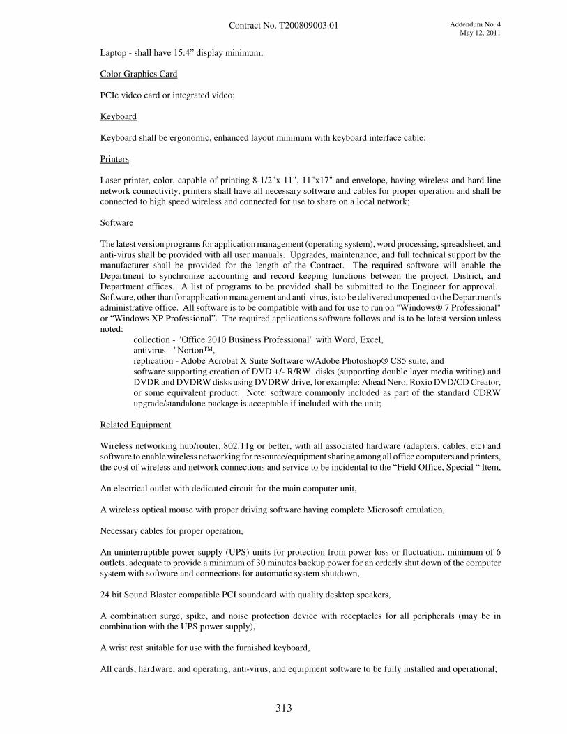
Addendum No. 4
May 12, 2011Contract No. T200809003.01
Laptop - shall have 15.4” display minimum;
Color Graphics Card
PCIe video card or integrated video;
Keyboard
Keyboard shall be ergonomic, enhanced layout minimum with keyboard interface cable;
Printers
Laser printer, color, capable of printing 8-1/2"x 11", 11"x17" and envelope, having wireless and hard line
network connectivity, printers shall have all necessary software and cables for proper operation and shall be
connected to high speed wireless and connected for use to share on a local network;
Software
The latest version programs for application management (operating system), word processing, spreadsheet, and
anti-virus shall be provided with all user manuals. Upgrades, maintenance, and full technical support by the
manufacturer shall be provided for the length of the Contract. The required software will enable the
Department to synchronize accounting and record keeping functions between the project, District, and
Department offices. A list of programs to be provided shall be submitted to the Engineer for approval.
Software, other than for application management and anti-virus, is to be delivered unopened to the Department's
administrative office. All software is to be compatible with and for use to run on "Windows® 7 Professional"
or “Windows XP Professional”. The required applications software follows and is to be latest version unless
noted:
collection - "Office 2010 Business Professional" with Word, Excel,
antivirus - "Norton™,
replication - Adobe Acrobat X Suite Software w/Adobe Photoshop® CS5 suite, and
software supporting creation of DVD +/- R/RW disks (supporting double layer media writing) and
DVDR and DVDRW disks using DVDRW drive, for example: Ahead Nero, Roxio DVD/CD Creator,
or some equivalent product. Note: software commonly included as part of the standard CDRW
upgrade/standalone package is acceptable if included with the unit;
Related Equipment
Wireless networking hub/router, 802.11g or better, with all associated hardware (adapters, cables, etc) and
software to enable wireless networking for resource/equipment sharing among all office computers and printers,
the cost of wireless and network connections and service to be incidental to the “Field Office, Special “ Item,
An electrical outlet with dedicated circuit for the main computer unit,
A wireless optical mouse with proper driving software having complete Microsoft emulation,
Necessary cables for proper operation,
An uninterruptible power supply (UPS) units for protection from power loss or fluctuation, minimum of 6
outlets, adequate to provide a minimum of 30 minutes backup power for an orderly shut down of the computer
system with software and connections for automatic system shutdown,
24 bit Sound Blaster compatible PCI soundcard with quality desktop speakers,
A combination surge, spike, and noise protection device with receptacles for all peripherals (may be in
combination with the UPS power supply),
A wrist rest suitable for use with the furnished keyboard,
All cards, hardware, and operating, anti-virus, and equipment software to be fully installed and operational;
313
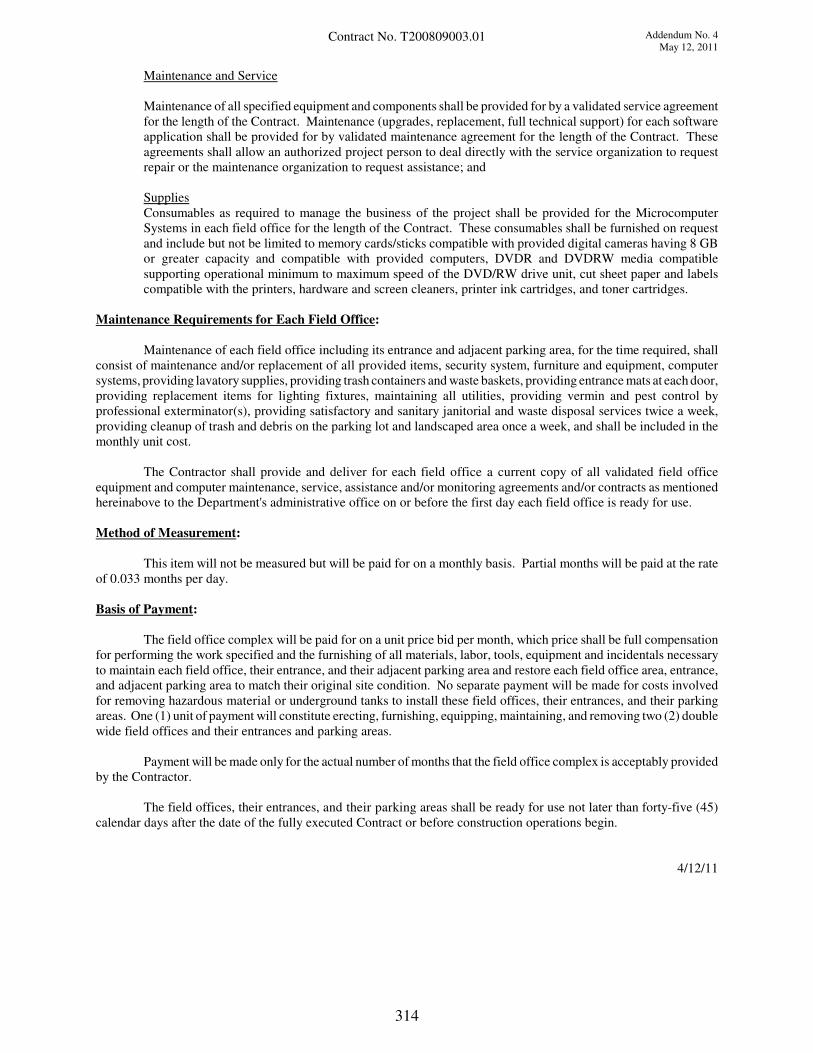
Addendum No. 4
May 12, 2011Contract No. T200809003.01
Maintenance and Service
Maintenance of all specified equipment and components shall be provided for by a validated service agreement
for the length of the Contract. Maintenance (upgrades, replacement, full technical support) for each software
application shall be provided for by validated maintenance agreement for the length of the Contract. These
agreements shall allow an authorized project person to deal directly with the service organization to request
repair or the maintenance organization to request assistance; and
Supplies
Consumables as required to manage the business of the project shall be provided for the Microcomputer
Systems in each field office for the length of the Contract. These consumables shall be furnished on request
and include but not be limited to memory cards/sticks compatible with provided digital cameras having 8 GB
or greater capacity and compatible with provided computers, DVDR and DVDRW media compatible
supporting operational minimum to maximum speed of the DVD/RW drive unit, cut sheet paper and labels
compatible with the printers, hardware and screen cleaners, printer ink cartridges, and toner cartridges.
Maintenance Requirements for Each Field Office:
Maintenance of each field office including its entrance and adjacent parking area, for the time required, shall
consist of maintenance and/or replacement of all provided items, security system, furniture and equipment, computer
systems, providing lavatory supplies, providing trash containers and waste baskets, providing entrance mats at each door,
providing replacement items for lighting fixtures, maintaining all utilities, providing vermin and pest control by
professional exterminator(s), providing satisfactory and sanitary janitorial and waste disposal services twice a week,
providing cleanup of trash and debris on the parking lot and landscaped area once a week, and shall be included in the
monthly unit cost.
The Contractor shall provide and deliver for each field office a current copy of all validated field office
equipment and computer maintenance, service, assistance and/or monitoring agreements and/or contracts as mentioned
hereinabove to the Department's administrative office on or before the first day each field office is ready for use.
Method of Measurement:
This item will not be measured but will be paid for on a monthly basis. Partial months will be paid at the rate
of 0.033 months per day.
Basis of Payment:
The field office complex will be paid for on a unit price bid per month, which price shall be full compensation
for performing the work specified and the furnishing of all materials, labor, tools, equipment and incidentals necessary
to maintain each field office, their entrance, and their adjacent parking area and restore each field office area, entrance,
and adjacent parking area to match their original site condition. No separate payment will be made for costs involved
for removing hazardous material or underground tanks to install these field offices, their entrances, and their parking
areas. One (1) unit of payment will constitute erecting, furnishing, equipping, maintaining, and removing two (2) double
wide field offices and their entrances and parking areas.
Payment will be made only for the actual number of months that the field office complex is acceptably provided
by the Contractor.
The field offices, their entrances, and their parking areas shall be ready for use not later than forty-five (45)
calendar days after the date of the fully executed Contract or before construction operations begin.
4/12/11
314
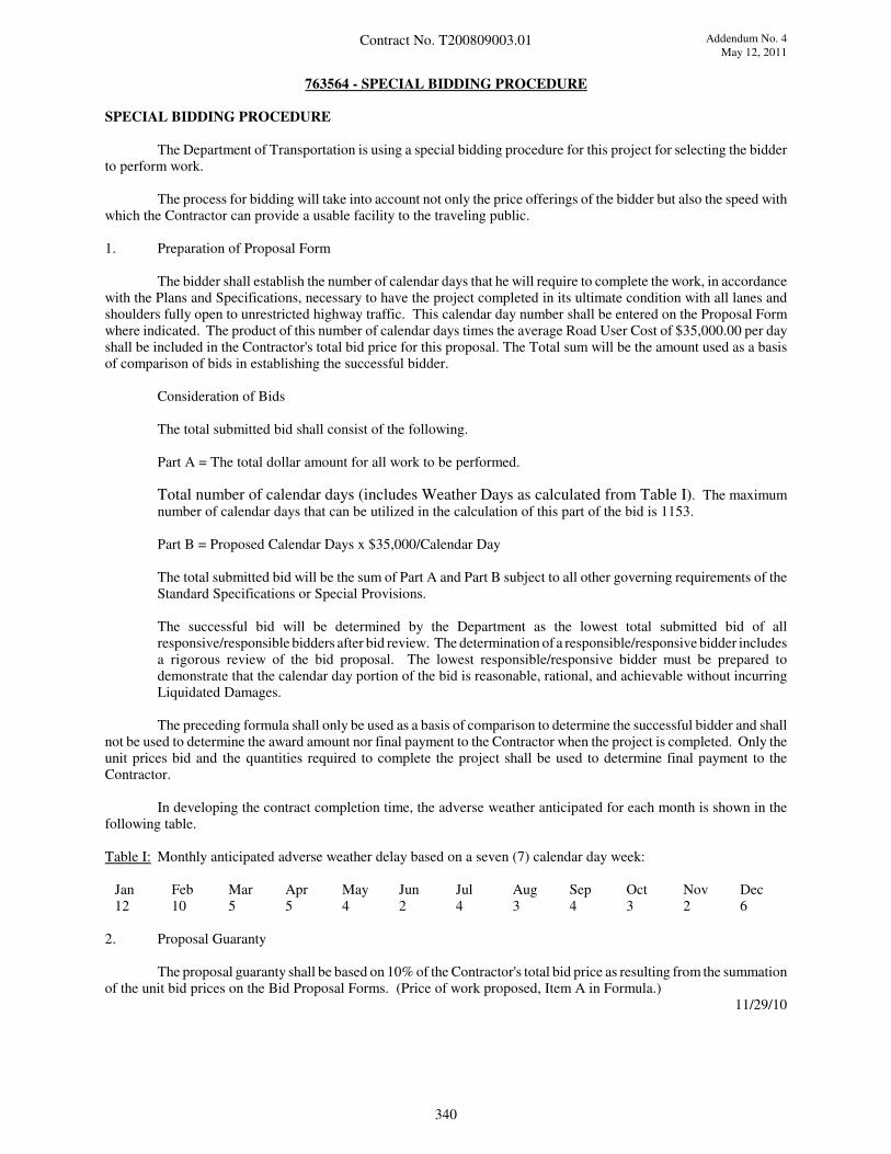
Addendum No. 4
May 12, 2011Contract No. T200809003.01
763564 - SPECIAL BIDDING PROCEDURE
SPECIAL BIDDING PROCEDURE
The Department of Transportation is using a special bidding procedure for this project for selecting the bidder
to perform work.
The process for bidding will take into account not only the price offerings of the bidder but also the speed with
which the Contractor can provide a usable facility to the traveling public.
1. Preparation of Proposal Form
The bidder shall establish the number of calendar days that he will require to complete the work, in accordance
with the Plans and Specifications, necessary to have the project completed in its ultimate condition with all lanes and
shoulders fully open to unrestricted highway traffic. This calendar day number shall be entered on the Proposal Form
where indicated. The product of this number of calendar days times the average Road User Cost of $35,000.00 per day
shall be included in the Contractor's total bid price for this proposal. The Total sum will be the amount used as a basis
of comparison of bids in establishing the successful bidder.
Consideration of Bids
The total submitted bid shall consist of the following.
Part A = The total dollar amount for all work to be performed.
Total number of calendar days (includes Weather Days as calculated from Table I). The maximumnumber of calendar days that can be utilized in the calculation of this part of the bid is 1153.
Part B = Proposed Calendar Days x $35,000/Calendar Day
The total submitted bid will be the sum of Part A and Part B subject to all other governing requirements of theStandard Specifications or Special Provisions.
The successful bid will be determined by the Department as the lowest total submitted bid of allresponsive/responsible bidders after bid review. The determination of a responsible/responsive bidder includesa rigorous review of the bid proposal. The lowest responsible/responsive bidder must be prepared todemonstrate that the calendar day portion of the bid is reasonable, rational, and achievable without incurringLiquidated Damages.
The preceding formula shall only be used as a basis of comparison to determine the successful bidder and shallnot be used to determine the award amount nor final payment to the Contractor when the project is completed. Only theunit prices bid and the quantities required to complete the project shall be used to determine final payment to the
Contractor.
In developing the contract completion time, the adverse weather anticipated for each month is shown in the
following table.
Table I: Monthly anticipated adverse weather delay based on a seven (7) calendar day week:
Jan Feb Mar Apr May Jun Jul Aug Sep Oct Nov Dec
12 10 5 5 4 2 4 3 4 3 2 6
2. Proposal Guaranty
The proposal guaranty shall be based on 10% of the Contractor's total bid price as resulting from the summation
of the unit bid prices on the Bid Proposal Forms. (Price of work proposed, Item A in Formula.)11/29/10
340
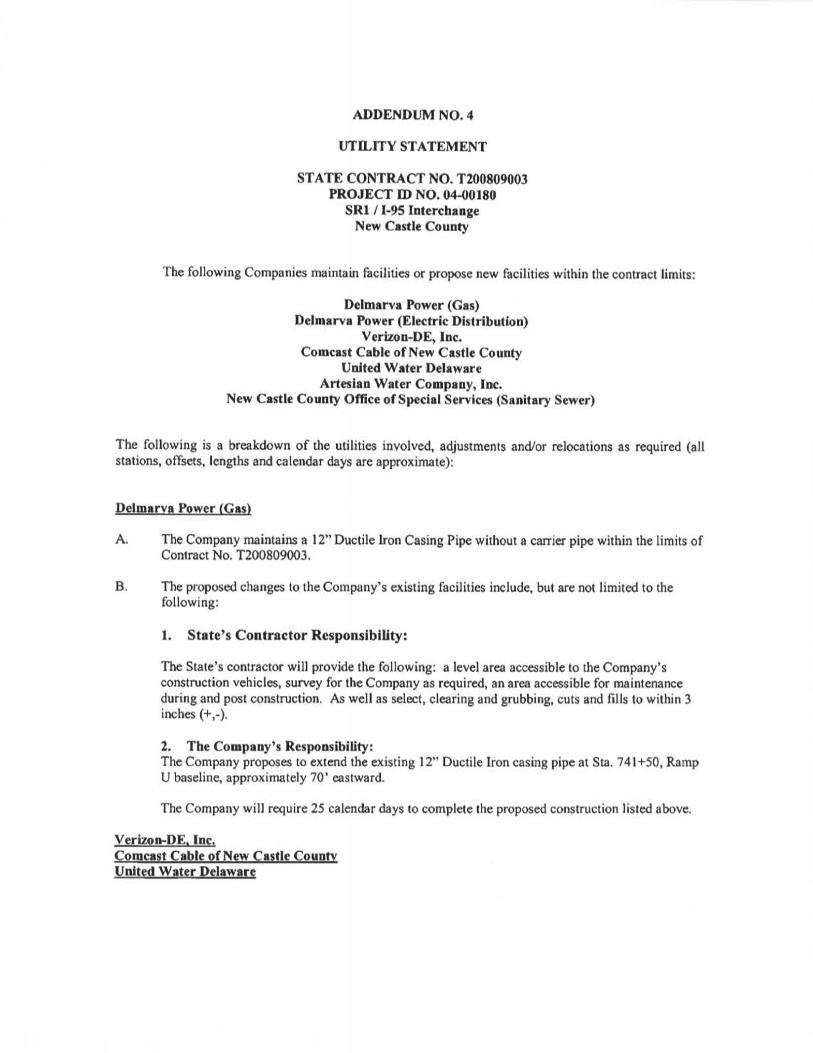
ADDENDUM NO. 4
UTILITY STATEMENT
STATE CONTRACT NO. T200809003PROJECT ID NO. 04-00180
SRI /1-95 InterchangeNew Castle County
The following Companies maintain facilities or propose new facilities within the contract limits:
Delmarva Power (Gas)Delmarva Power (Electric Distribution)
Verizon-DE, Inc.Comcast Cable of New Castle County
United Water DelawareArtesian Water Company, Inc.
New Castle County Office of Special Services (Sanitary Sewer)
The following is a breakdown of the utilities involved, adjustments and/or relocations as required (allstations, offsets, lengths and calendar days are approximate):
Delmarva Power (Gas)
A. The Company maintains a 12" Ductile Iron Casing Pipe without a carrier pipe within the limits ofContract No. T200809003.
B. The proposed changes to the Company's existing facilities include, but are not limited to thefollowing:
1. State's Contractor Responsibility:
The State's contractor will provide the following: a level area accessible to the Company'sconstruction vehicles, survey for the Company as required, an area accessible for maintenanceduring and post construction. As well as select, clearing and grubbing, cuts and fills to within 3inches (+,-).
2. The Company's Responsibility:The Company proposes to extend the existing 12" Ductile Iron casing pipe at Sta. 741+50, RampU baseline, approximately 70' eastward.
The Company will require 25 calendar days to complete the proposed construction listed above.
Verizon-DE. Inc.Comcast Cable of New Castle CountyUnited Water Delaware
Contract No. T200809003
A. The aforementioned Companies maintain aerial, underground and/or buried facilities within thelimits of Contract T200809003 with no apparent conflicts with the proposed constructionactivities.
B. Any relocations/adjustments to the aforementioned Companies' existing facilities that may ariseduring construction will be performed by the appropriate Company's forces during constructionof this project. The time to complete any relocations/adjustments will depend on the nature of thework.
Artesian Water Company. Inc.
A. The Company maintains underground facilities within the limits of Contract T200809003.
B. The Company will perform the following relocations during the State contract to eliminateconflicts with the proposed roadway construction.
1. Ramp A, Sta. 1268+50 to Sta. 1268+85, offset 150' left. The Company will relocate theexisting 12-in DIP with approximately 100 feet of new 12-in DIP in 20-in STL casing toavoid conflict with the proposed roadway excavation. The Company will require fourteen(14) calendar days to complete the proposed work following twenty-eight (28) calendar daysadvance notice and completion of the Utility Pre-Construction Meeting for this contract. TheState's Contractor shall furnish 50 cubic yards of Borrow Type C for this relocation.
2. Ramp E, Sta. 516+40 to Sta. 517+40, offset 80' right. The company will relocate the existing16-in DIP with approximately 110 feet of new 16-in DIP to avoid conflict with proposedaccess ramp. The company will require fourteen (14) calendar days to complete the proposedwork following twenty-eight (28) calendar days advance notice and completion of the UtilityPre-Construction Meeting for this contract. The State's Contractor shall furnish 10 cubicyards of Borrow Type C for this relocation.
3. Ramp C, Sta. 1101+60. The Company will install approximately 750 feet of 20-in HOPEcarrier pipe in 30-in HDPE casing pipe under existing 1-95 by directional drill method toestablish a critical second feed to the mall region. The Company will require forty-two (42)calendar days to complete the proposed work following twenty-eight (28) calendar daysadvance notice and completion of the Utility Pre-Construction Meeting for this contract.
The Company will abandon in place the existing water facilities after the relocated water facilities areinstalled and activated with services tied over. The Company estimates that the identified relocationactivities will take place during Contract No. T200809003 and within the State Contractor's constructionphasing and maintenance of traffic plan. In addition, system demands and effected customers mayrequire the Company to perform relocation activities during overnight hours.
Delmarva Power (Electric Distribution)
A. The Company maintains aerial, underground and/or buried facilities within the limits of ContractT200809003.
B. The proposed changes to the Company's existing facilities include, but are not limited to thefollowing:
NOTE: AT ALL SWITCHGEAR AND TRANSFORMER LOCATIONS, DELMARVAWDLL REQUIRE A 12 FOOT CLEARANCE ON THE FRONT SIDE OF THE DEVICE
Contract No. T200809003
AND A MINIMUM OF 4 FEET ON THE OTHER SIDES WITH NO OBSTRUCTIONSSUCH AS FENCE, WALL, SHRUBS AND ANY OTHER STRUCTURES.
Outages on the 12kv and 34kv circuits will only be permitted as load, weather and other systemconditions permit.
1. State's Contractor Responsibility
The State's Contractor will provide the following: a level area accessible to the Company'sconstruction vehicles, survey for the Company as required, an area accessible for maintenanceduring and post construction. As well as select, clearing and grubbing, cuts and fills to within 3inches (+,-).
2. The Company's Responsibility
The Company proposes to relocate the existing two (2) 34kv circuits and one (1) 12kv circuit in a6 way (6 inch ducts) manhole/ conduit system along Ramp C beginning at approximately Sta.1104+50, Ramp C baseline to Sta. 1108+00, Ramp C baseline, then continuing along and underthe SW Loop ramp from Sta. 1908+50, SW Loop baseline to Sta. 1904+50, SW Loop baseline,then crossing under SW Loop ramp and Ramp C to a proposed manhole, then continuing underRamp Cl near Sta. 1813+75, then paralleling Ramp Gl from Sta. 1316+50, Ramp Gl baseline toa manhole near Sta. 1317+00. From the manhole near Sta. 1317+00, Ramp Gl baseline, the two34kv circuits in a 4 way (8 inch ducts) will be bored under SR 1 to a proposed manhole within theMall parking lot and tie into an 4 way (5 inch ducts) existing ductbank.
The existing 12kv circuit will continue from the proposed manhole near Sta. 1317+00, Ramp Glbaseline to a proposed PMH-9 switchgear, then continue to the south and stub up the proposedterminal pole with guy anchors near Sta. 1320+50, Ramp Gl baseline. The Company will installtwo additional proposed poles along Stanton Christiana Road and connect to the existing 3 phase12kv service pole near Sta. 2014+00, Stanton Christiana Road baseline. The 12 kv will alsoconnect to the existing pole near Sta. 2016+50 and the Company will install a pushpole brace onthe existing pole.
LIGHTING - Ramp Gl Location - The Company will furnish and install a transformer, fedfrom the proposed PMH-9 switchgear, near the proposed DelDOT lighting cabinet and DelDOTservice pedestal adjacent to Ramp Gl. This switchgear and transformer will provide three-phase277/480V service for the lighting cabinet along Ramp Gl. DelDOT will furnish and installconduit and cables from the service pedestal to the proposed transformer. The Company willassist DelDOT in making the final connections at the transformer. The Company will furnish andinstall all conduit and cables from the transformer to the switchgear.
LIGHTING - Churchmans Road Location - The Company will furnish and install a basemounted transformer near the proposed DelDOT lighting cabinet and DelDOT service pedestal,which will be located at the Churchmans Road interchange in the quadrant south of Churchmansroad and north of 1-95. The transformer will provide three-phase 277/480V service for thelighting cabinet along Churchmans Road. DelDOT will furnish and install conduit and cablesfrom the service pedestal to the proposed transformer. The Company will assist DelDOT inmaking the final connections from at the transformer. The Company will furnish and install allconduit and cables from the transformer to the existing utility pole.
Scheduling of outage and tie over for Existing Circuits:
Contract No. T200809003
Overtime will be required in order to splice, terminate and tie in new circuits into the Company'sexisting electrical system. This will include nights and weekend work. No outages will bepermitted during the months of July and August. Outages may be restricted in September in theevent of hot weather.
Company Review of Field Changes
The Company maintains the right to review/ approve any design changes submitted by theEngineer as well as the right to review any field changes that could impact the construction of theCompany's facilities.
Lead-Time for Cable and Associated Materials (16-23 Weeks)
The lead time to procure these materials could possibly increase due to the economic situationand suppliers eliminating shifts.
NOTE: ESTIMATE DOES NOT INCLUDE COSTS FOR THE FOLLOWING:
REMOVAL/ BLASTING OF ROCK, CLEARING AND GRUBBING, REMOVAL OF SPOILSFROM SITE, SELECT TO BE PROVIDED BY DELDOT, RESTORATION COST NOTINCLUDED, REMOVAL AND DISPOSAL OF ANY CONTAMINATED DIRT OR WATER,MAINTAINING EXISTING U.G. & AERIAL FACILITIES DURING ROADCONSTRUCTION PHASE.
The Company will require one hundred (100) calendar days to complete the proposed manhole andconduit system and an additional ninety (90) calendar days to complete the cable and splicing work,following twenty-eight (28) calendar days advance notice of completion of clearing and grubbing, cutsand fills made, staking of rights-of-way and completion of the Utility Pre-Construction Meeting for thiscontract and the procurement of easements by DelDOT and receipt of "NTF'.
New Castle County Office of Special Services (Sanitary Sewer)
Any adjustments and/or relocations of the County's existing sanitary sewer facilities will be done by theState's Contractor in accordance with the County's Standard Specifications, as indicated on the plans andoutlined elsewhere in these Special Provisions.
GENERAL NOTES:
1. THE UTILITIES AND THEIR CONTRACTORS DO NOT NORMALLY WORK ONWEEKENDS OR LEGAL HOLIDAYS!
2. IT IS UNDERSTOOD AND AGREED THAT THE STATE'S CONTRACTOR HASCONSIDERED IN HIS BID ALL PERMANENT AND TEMPORARY UTILITYAPPURTENANCES IN THEIR PRESENT OR RELOCATED POSITIONS AS SHOWN ON THEPLANS OR DESCRD3ED IN THE UTILITY STATEMENT AND/OR ARE READILYDISCERNIBLE AND THAT NO ADDITIONAL COMPENSATION WELL BE ALLOWED FORANY DELAYS, INCONVENIENCE, OR DAMAGE SUSTAINED BY HIM/HER DUE TO ANY

Contract No. T200809003
INTERFERENCE FROM THE SAID UTILITY FAdLITDZS AND APPURTENANCES OR THEOPERATION OF MOVING THEM, EXCEPT THAT THE STATE'S CONTRACTORS MAY BEGRANTED AN EQUITABLE EXTENSION OF TIME. THE STATE'S CONTRACTOR ISRESPONSIBLE FOR THE SUPPORT AND PROTECTION OF ALL UTILITIES WHENEXCAVATING.
3. THE STATE'S CONTRACTOR IS RESPONSIBLE FOR ROUGH GRADING ASREQUHIED BY THE ROADWAY CONSTRUCTION PRIOR TO THE UTILITY COMPANY'SPLACING THEIR PROPOSED FACILITIES, UNLESS INDICATED ON THE PLANS AND/OROUTLINED ELSEWHERE IN THESE SPECIFICATIONS.
4. FOR EXACT LOCATION OF EXISTING FACDLITDZS, PLEASE CONTACT MISSUTILITY AT (800) 282-8555. 16 DEL. C. § 7405B REQUIRES NOTIFICATION TO ANDMUTUALLY AGREEABLE MEASURES FROM THE PUBLIC UTDLITY FROM ANY PERSONINTENDING TO CARRY ON ANY FUNCTION, ACTIVITY, WORK OR OPERATIONWITHIN DANGEROUS PROXIMITY OF ANY HIGH VOLTAGE OVERHEAD LINE.
5. COORDINATION AND COOPERATION AMONG THE IHTLITY COMPANIES AND THESTATE'S CONTRACTOR ARE OF PRIME IMPORTANCE. THEREFORE, THECONTRACTOR IS DmECTED TO CONTACT THE FOLLOWING UTILITY COMPANYREPRESENTATIVES WITH ANY QUESTIONS REGARDING THIS WORK PRIOR TOSUBMITTING BIDS AND WORK SCHEDULES. PROPOSED WORK SCHEDULES SHALLREFLECT THE UTILITY COMPANIES' PROPOSED RELOCATIONS.
Ted WaughAngel CollazoGeorge ZangKnol McRaeJohn LichtCarmen HunterKevin Penoza
Delmarva Power (Gas) (302) 429-3706Delmarva Power (Electric Distribution) (302) 454-4370Verizon-DE, Inc. (610) 280-5574Comcast Cable of New Castle County (302) 661-4431United Water Delaware (302) 633-5905Artesian Water Company, Inc. (302) 453-6900New Castle County Office of (302) 395-5723Special Services (Sanitary Sewer)
PREPARED AND RECOMMENDED BY:
0<4.Pummel,
ConsultingykngineersDate
APPROVED AS TO FORM:
Utilities Engi Date

DELAWARE DEPARTMENT OF TRANSPORTATION PAGE: 1
SCHEDULE OF ITEMS DATE:
CONTRACT ID: T200809003.01 PROJECT(S): IM-N056(35)
All figures must be typewritten.
CONTRACTOR :________________________________________________________________
-------------------------------------------------------------------------------
LINE| ITEM | APPROX. | UNIT PRICE | BID AMOUNT
NO | DESCRIPTION | QUANTITY |----------------|--------------
| | AND UNITS | DOLLARS | CTS | DOLLARS |CTS
-------------------------------------------------------------------------------
SECTION 0001 ROAD
-------------------------------------------------------------------------------
|201000 CLEARING AND | | |
0010|GRUBBING |LUMP |LUMP |
| | | |
-------------------------------------------------------------------------------
|202000 EXCAVATION AND | | |
0020|EMBANKMENT | 314000.000| |
| |CY | |
-------------------------------------------------------------------------------
|202505 SETTLEMENT | | |
0030|PLATFORM | 18.000| |
| |EACH | |
-------------------------------------------------------------------------------
|202514 PIEZOMETER | | |
0040| | 4.000| |
| |EACH | |
-------------------------------------------------------------------------------
|202518 SETTLEMENT | | |
0050|MONUMENT | 57.000| |
| |EACH | |
-------------------------------------------------------------------------------
|202555 SUBSOIL TILLAGE | | |
0060| | 2700.000| |
| |SY | |
-------------------------------------------------------------------------------
|207000 EXCAVATION AND | | |
0070|BACKFILL FOR STRUCTURES | 3415.000| |
| |CY | |
-------------------------------------------------------------------------------
|208000 EXCAVATION AND | | |
0090|BACKFILLING FOR PIPE | 9249.000| |
|TRENCHES |CY | |
-------------------------------------------------------------------------------
|208500 FLOWABLE FILL | | |
0100| | 160.000| |
| |CY | |
-------------------------------------------------------------------------------
|209001 BORROW, TYPE A | | |
0110| | 3325.000| |
| |CY | |
-------------------------------------------------------------------------------
Addendum No. 4
May 12, 2011
CANNOT BE USED FOR BIDDING

Addendum No. 4
May 12, 2011
CANNOT BE USED FOR BIDDING
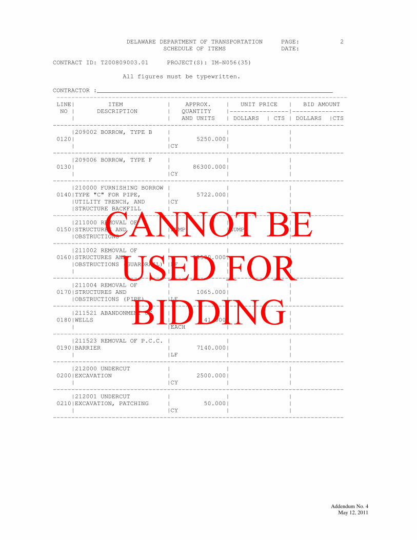
DELAWARE DEPARTMENT OF TRANSPORTATION PAGE: 2
SCHEDULE OF ITEMS DATE:
CONTRACT ID: T200809003.01 PROJECT(S): IM-N056(35)
All figures must be typewritten.
CONTRACTOR :________________________________________________________________
-------------------------------------------------------------------------------
LINE| ITEM | APPROX. | UNIT PRICE | BID AMOUNT
NO | DESCRIPTION | QUANTITY |----------------|--------------
| | AND UNITS | DOLLARS | CTS | DOLLARS |CTS
-------------------------------------------------------------------------------
|209002 BORROW, TYPE B | | |
0120| | 5250.000| |
| |CY | |
-------------------------------------------------------------------------------
|209006 BORROW, TYPE F | | |
0130| | 86300.000| |
| |CY | |
-------------------------------------------------------------------------------
|210000 FURNISHING BORROW | | |
0140|TYPE "C" FOR PIPE, | 5722.000| |
|UTILITY TRENCH, AND |CY | |
|STRUCTURE BACKFILL | | |
-------------------------------------------------------------------------------
|211000 REMOVAL OF | | |
0150|STRUCTURES AND |LUMP |LUMP |
|OBSTRUCTIONS | | |
-------------------------------------------------------------------------------
|211002 REMOVAL OF | | |
0160|STRUCTURES AND | 11500.000| |
|OBSTRUCTIONS (GUARDRAIL) |LF | |
| | | |
-------------------------------------------------------------------------------
|211004 REMOVAL OF | | |
0170|STRUCTURES AND | 1065.000| |
|OBSTRUCTIONS (PIPE) |LF | |
-------------------------------------------------------------------------------
|211521 ABANDONMENT OF | | |
0180|WELLS | 41.000| |
| |EACH | |
-------------------------------------------------------------------------------
|211523 REMOVAL OF P.C.C. | | |
0190|BARRIER | 7140.000| |
| |LF | |
-------------------------------------------------------------------------------
|212000 UNDERCUT | | |
0200|EXCAVATION | 2500.000| |
| |CY | |
-------------------------------------------------------------------------------
|212001 UNDERCUT | | |
0210|EXCAVATION, PATCHING | 50.000| |
| |CY | |
-------------------------------------------------------------------------------
Addendum No. 4
May 12, 2011
CANNOT BE USED FOR BIDDING

Addendum No. 4
May 12, 2011
CANNOT BE USED FOR BIDDING
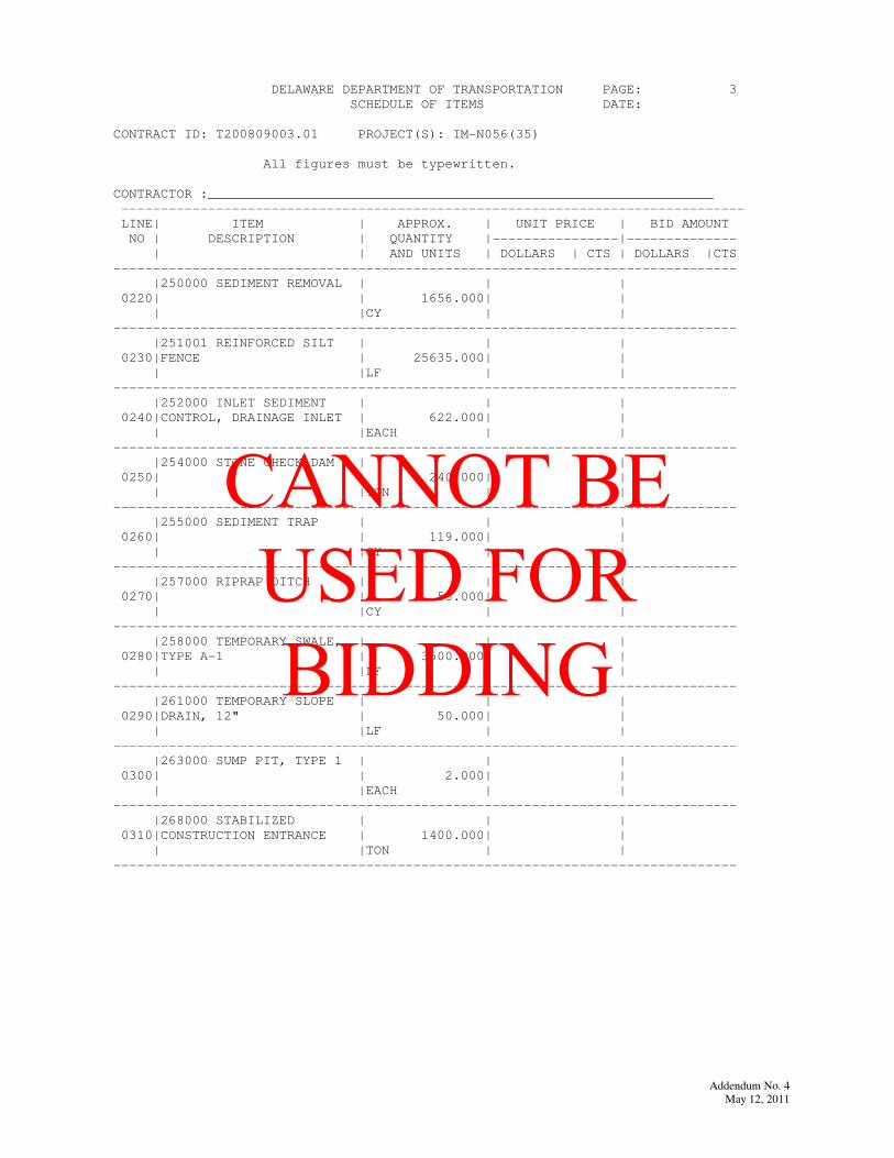
DELAWARE DEPARTMENT OF TRANSPORTATION PAGE: 3
SCHEDULE OF ITEMS DATE:
CONTRACT ID: T200809003.01 PROJECT(S): IM-N056(35)
All figures must be typewritten.
CONTRACTOR :________________________________________________________________
-------------------------------------------------------------------------------
LINE| ITEM | APPROX. | UNIT PRICE | BID AMOUNT
NO | DESCRIPTION | QUANTITY |----------------|--------------
| | AND UNITS | DOLLARS | CTS | DOLLARS |CTS
-------------------------------------------------------------------------------
|250000 SEDIMENT REMOVAL | | |
0220| | 1656.000| |
| |CY | |
-------------------------------------------------------------------------------
|251001 REINFORCED SILT | | |
0230|FENCE | 25635.000| |
| |LF | |
-------------------------------------------------------------------------------
|252000 INLET SEDIMENT | | |
0240|CONTROL, DRAINAGE INLET | 622.000| |
| |EACH | |
-------------------------------------------------------------------------------
|254000 STONE CHECK DAM | | |
0250| | 240.000| |
| |TON | |
-------------------------------------------------------------------------------
|255000 SEDIMENT TRAP | | |
0260| | 119.000| |
| |CY | |
-------------------------------------------------------------------------------
|257000 RIPRAP DITCH | | |
0270| | 55.000| |
| |CY | |
-------------------------------------------------------------------------------
|258000 TEMPORARY SWALE, | | |
0280|TYPE A-1 | 3500.000| |
| |LF | |
-------------------------------------------------------------------------------
|261000 TEMPORARY SLOPE | | |
0290|DRAIN, 12" | 50.000| |
| |LF | |
-------------------------------------------------------------------------------
|263000 SUMP PIT, TYPE 1 | | |
0300| | 2.000| |
| |EACH | |
-------------------------------------------------------------------------------
|268000 STABILIZED | | |
0310|CONSTRUCTION ENTRANCE | 1400.000| |
| |TON | |
-------------------------------------------------------------------------------
Addendum No. 4
May 12, 2011
CANNOT BE USED FOR BIDDING

Addendum No. 4
May 12, 2011
CANNOT BE USED FOR BIDDING
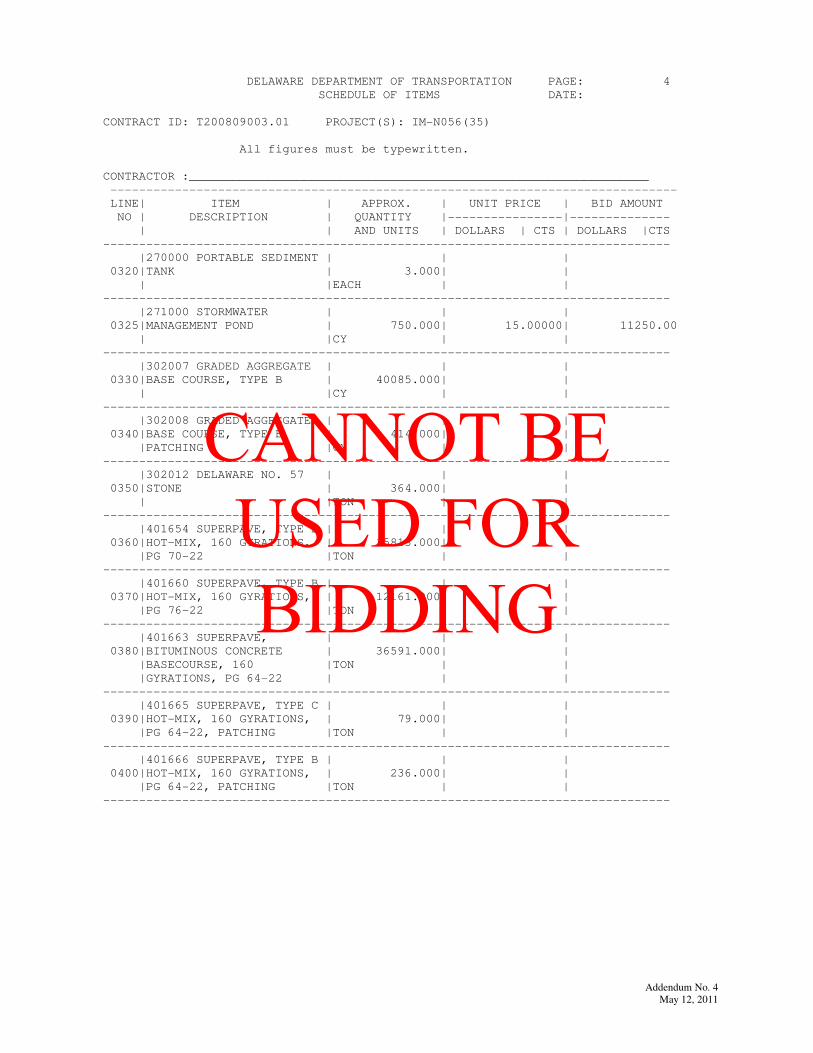
DELAWARE DEPARTMENT OF TRANSPORTATION PAGE: 4
SCHEDULE OF ITEMS DATE:
CONTRACT ID: T200809003.01 PROJECT(S): IM-N056(35)
All figures must be typewritten.
CONTRACTOR :________________________________________________________________
-------------------------------------------------------------------------------
LINE| ITEM | APPROX. | UNIT PRICE | BID AMOUNT
NO | DESCRIPTION | QUANTITY |----------------|--------------
| | AND UNITS | DOLLARS | CTS | DOLLARS |CTS
-------------------------------------------------------------------------------
|270000 PORTABLE SEDIMENT | | |
0320|TANK | 3.000| |
| |EACH | |
-------------------------------------------------------------------------------
|271000 STORMWATER | | |
0325|MANAGEMENT POND | 750.000| 15.00000| 11250.00
| |CY | |
-------------------------------------------------------------------------------
|302007 GRADED AGGREGATE | | |
0330|BASE COURSE, TYPE B | 40085.000| |
| |CY | |
-------------------------------------------------------------------------------
|302008 GRADED AGGREGATE | | |
0340|BASE COURSE, TYPE B, | 414.000| |
|PATCHING |CY | |
-------------------------------------------------------------------------------
|302012 DELAWARE NO. 57 | | |
0350|STONE | 364.000| |
| |TON | |
-------------------------------------------------------------------------------
|401654 SUPERPAVE, TYPE B | | |
0360|HOT-MIX, 160 GYRATIONS, | 15813.000| |
|PG 70-22 |TON | |
-------------------------------------------------------------------------------
|401660 SUPERPAVE, TYPE B | | |
0370|HOT-MIX, 160 GYRATIONS, | 12161.000| |
|PG 76-22 |TON | |
-------------------------------------------------------------------------------
|401663 SUPERPAVE, | | |
0380|BITUMINOUS CONCRETE | 36591.000| |
|BASECOURSE, 160 |TON | |
|GYRATIONS, PG 64-22 | | |
-------------------------------------------------------------------------------
|401665 SUPERPAVE, TYPE C | | |
0390|HOT-MIX, 160 GYRATIONS, | 79.000| |
|PG 64-22, PATCHING |TON | |
-------------------------------------------------------------------------------
|401666 SUPERPAVE, TYPE B | | |
0400|HOT-MIX, 160 GYRATIONS, | 236.000| |
|PG 64-22, PATCHING |TON | |
-------------------------------------------------------------------------------
Addendum No. 4
May 12, 2011
CANNOT BE USED FOR BIDDING

Addendum No. 4
May 12, 2011
CANNOT BE USED FOR BIDDING
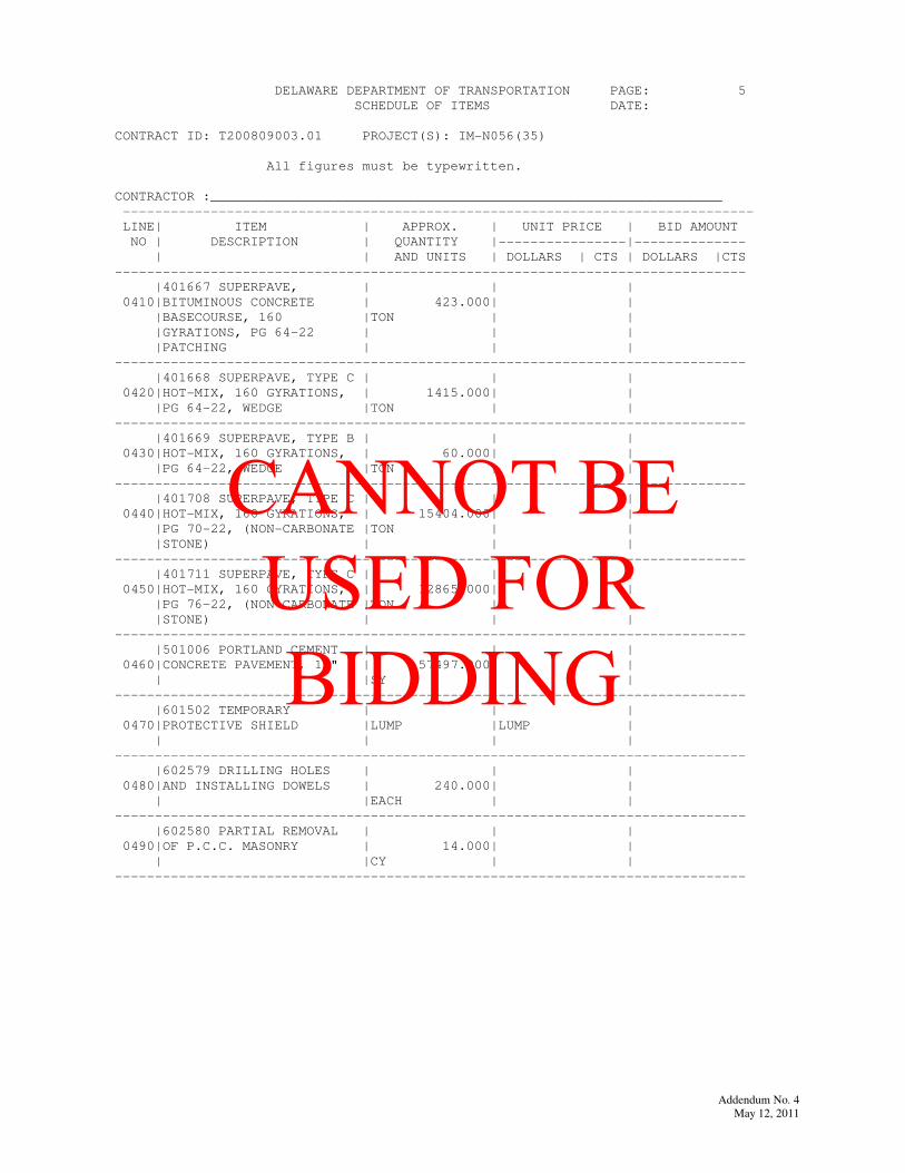
DELAWARE DEPARTMENT OF TRANSPORTATION PAGE: 5
SCHEDULE OF ITEMS DATE:
CONTRACT ID: T200809003.01 PROJECT(S): IM-N056(35)
All figures must be typewritten.
CONTRACTOR :________________________________________________________________
-------------------------------------------------------------------------------
LINE| ITEM | APPROX. | UNIT PRICE | BID AMOUNT
NO | DESCRIPTION | QUANTITY |----------------|--------------
| | AND UNITS | DOLLARS | CTS | DOLLARS |CTS
-------------------------------------------------------------------------------
|401667 SUPERPAVE, | | |
0410|BITUMINOUS CONCRETE | 423.000| |
|BASECOURSE, 160 |TON | |
|GYRATIONS, PG 64-22 | | |
|PATCHING | | |
-------------------------------------------------------------------------------
|401668 SUPERPAVE, TYPE C | | |
0420|HOT-MIX, 160 GYRATIONS, | 1415.000| |
|PG 64-22, WEDGE |TON | |
-------------------------------------------------------------------------------
|401669 SUPERPAVE, TYPE B | | |
0430|HOT-MIX, 160 GYRATIONS, | 60.000| |
|PG 64-22, WEDGE |TON | |
-------------------------------------------------------------------------------
|401708 SUPERPAVE, TYPE C | | |
0440|HOT-MIX, 160 GYRATIONS, | 15404.000| |
|PG 70-22, (NON-CARBONATE |TON | |
|STONE) | | |
-------------------------------------------------------------------------------
|401711 SUPERPAVE, TYPE C | | |
0450|HOT-MIX, 160 GYRATIONS, | 12865.000| |
|PG 76-22, (NON-CARBONATE |TON | |
|STONE) | | |
-------------------------------------------------------------------------------
|501006 PORTLAND CEMENT | | |
0460|CONCRETE PAVEMENT, 12" | 57497.000| |
| |SY | |
-------------------------------------------------------------------------------
|601502 TEMPORARY | | |
0470|PROTECTIVE SHIELD |LUMP |LUMP |
| | | |
-------------------------------------------------------------------------------
|602579 DRILLING HOLES | | |
0480|AND INSTALLING DOWELS | 240.000| |
| |EACH | |
-------------------------------------------------------------------------------
|602580 PARTIAL REMOVAL | | |
0490|OF P.C.C. MASONRY | 14.000| |
| |CY | |
-------------------------------------------------------------------------------
Addendum No. 4
May 12, 2011
CANNOT BE USED FOR BIDDING

Addendum No. 4
May 12, 2011
CANNOT BE USED FOR BIDDING
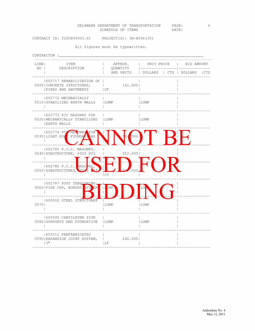
DELAWARE DEPARTMENT OF TRANSPORTATION PAGE: 6
SCHEDULE OF ITEMS DATE:
CONTRACT ID: T200809003.01 PROJECT(S): IM-N056(35)
All figures must be typewritten.
CONTRACTOR :________________________________________________________________
-------------------------------------------------------------------------------
LINE| ITEM | APPROX. | UNIT PRICE | BID AMOUNT
NO | DESCRIPTION | QUANTITY |----------------|--------------
| | AND UNITS | DOLLARS | CTS | DOLLARS |CTS
-------------------------------------------------------------------------------
|602717 REHABILITATION OF | | |
0500|CONCRETE STRUCTURES, | 141.000| |
|PIERS AND ABUTMENTS |CF | |
-------------------------------------------------------------------------------
|602772 MECHANICALLY | | |
0510|STABILIZED EARTH WALLS |LUMP |LUMP |
| | | |
-------------------------------------------------------------------------------
|602773 PCC MASONRY FOR | | |
0520|MECHANICALLY STABILIZED |LUMP |LUMP |
|EARTH WALLS | | |
-------------------------------------------------------------------------------
|602774 PCC MASONRY FOR | | |
0530|LIGHT POLE FOUNDATIONS | 304.000| |
| |CY | |
-------------------------------------------------------------------------------
|602785 P.C.C. MASONRY, | | |
0540|SUBSTRUCTURE, 6000 PSI | 252.000| |
| |CY | |
-------------------------------------------------------------------------------
|602786 P.C.C. MASONRY, | | |
0550|SUBSTRUCTURES, 8000 PSI | 472.000| |
| |CY | |
-------------------------------------------------------------------------------
|602787 POST TENSIONING | | |
0560|PIER CAP, BONDED SYSTEM |LUMP |LUMP |
| | | |
-------------------------------------------------------------------------------
|605002 STEEL STRUCTURES | | |
0570| |LUMP |LUMP |
| | | |
-------------------------------------------------------------------------------
|605500 CANTILEVER SIGN | | |
0580|SUPPORTS AND FOUNDATION |LUMP |LUMP |
| | | |
-------------------------------------------------------------------------------
|605511 PREFABRICATED | | |
0590|EXPANSION JOINT SYSTEM, | 240.000| |
|3" |LF | |
-------------------------------------------------------------------------------
Addendum No. 4
May 12, 2011
CANNOT BE USED FOR BIDDING

Addendum No. 4
May 12, 2011
CANNOT BE USED FOR BIDDING
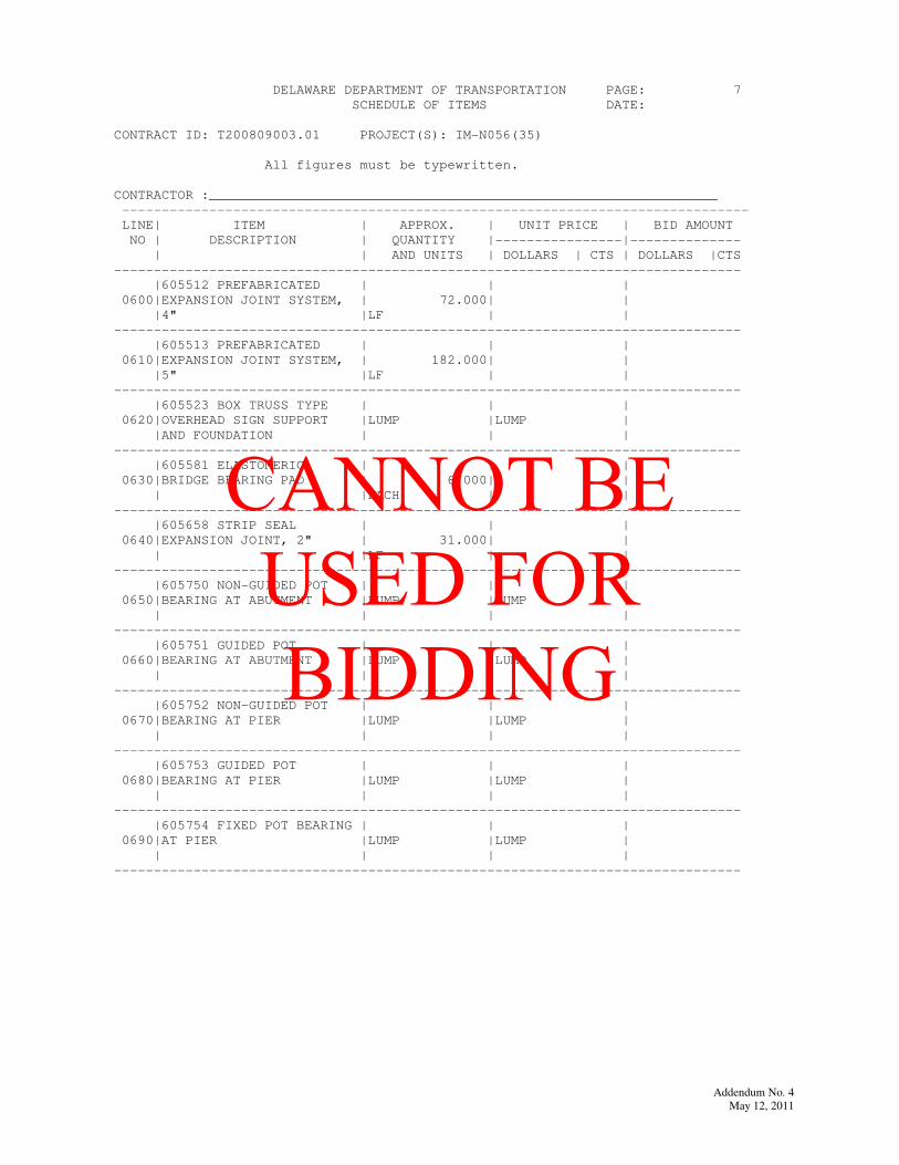
DELAWARE DEPARTMENT OF TRANSPORTATION PAGE: 7
SCHEDULE OF ITEMS DATE:
CONTRACT ID: T200809003.01 PROJECT(S): IM-N056(35)
All figures must be typewritten.
CONTRACTOR :________________________________________________________________
-------------------------------------------------------------------------------
LINE| ITEM | APPROX. | UNIT PRICE | BID AMOUNT
NO | DESCRIPTION | QUANTITY |----------------|--------------
| | AND UNITS | DOLLARS | CTS | DOLLARS |CTS
-------------------------------------------------------------------------------
|605512 PREFABRICATED | | |
0600|EXPANSION JOINT SYSTEM, | 72.000| |
|4" |LF | |
-------------------------------------------------------------------------------
|605513 PREFABRICATED | | |
0610|EXPANSION JOINT SYSTEM, | 182.000| |
|5" |LF | |
-------------------------------------------------------------------------------
|605523 BOX TRUSS TYPE | | |
0620|OVERHEAD SIGN SUPPORT |LUMP |LUMP |
|AND FOUNDATION | | |
-------------------------------------------------------------------------------
|605581 ELASTOMERIC | | |
0630|BRIDGE BEARING PAD | 6.000| |
| |EACH | |
-------------------------------------------------------------------------------
|605658 STRIP SEAL | | |
0640|EXPANSION JOINT, 2" | 31.000| |
| |LF | |
-------------------------------------------------------------------------------
|605750 NON-GUIDED POT | | |
0650|BEARING AT ABUTMENT |LUMP |LUMP |
| | | |
-------------------------------------------------------------------------------
|605751 GUIDED POT | | |
0660|BEARING AT ABUTMENT |LUMP |LUMP |
| | | |
-------------------------------------------------------------------------------
|605752 NON-GUIDED POT | | |
0670|BEARING AT PIER |LUMP |LUMP |
| | | |
-------------------------------------------------------------------------------
|605753 GUIDED POT | | |
0680|BEARING AT PIER |LUMP |LUMP |
| | | |
-------------------------------------------------------------------------------
|605754 FIXED POT BEARING | | |
0690|AT PIER |LUMP |LUMP |
| | | |
-------------------------------------------------------------------------------
Addendum No. 4
May 12, 2011
CANNOT BE USED FOR BIDDING

Addendum No. 4
May 12, 2011
CANNOT BE USED FOR BIDDING
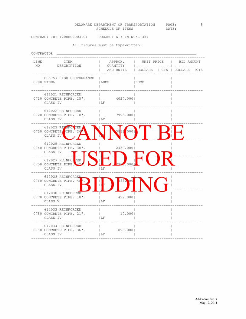
DELAWARE DEPARTMENT OF TRANSPORTATION PAGE: 8
SCHEDULE OF ITEMS DATE:
CONTRACT ID: T200809003.01 PROJECT(S): IM-N056(35)
All figures must be typewritten.
CONTRACTOR :________________________________________________________________
-------------------------------------------------------------------------------
LINE| ITEM | APPROX. | UNIT PRICE | BID AMOUNT
NO | DESCRIPTION | QUANTITY |----------------|--------------
| | AND UNITS | DOLLARS | CTS | DOLLARS |CTS
-------------------------------------------------------------------------------
|605757 HIGH PERFORMANCE | | |
0700|STEEL |LUMP |LUMP |
| | | |
-------------------------------------------------------------------------------
|612021 REINFORCED | | |
0710|CONCRETE PIPE, 15", | 4027.000| |
|CLASS IV |LF | |
-------------------------------------------------------------------------------
|612022 REINFORCED | | |
0720|CONCRETE PIPE, 18", | 7993.000| |
|CLASS IV |LF | |
-------------------------------------------------------------------------------
|612023 REINFORCED | | |
0730|CONCRETE PIPE, 24", | 3811.000| |
|CLASS IV |LF | |
-------------------------------------------------------------------------------
|612025 REINFORCED | | |
0740|CONCRETE PIPE, 30", | 2430.000| |
|CLASS IV |LF | |
-------------------------------------------------------------------------------
|612027 REINFORCED | | |
0750|CONCRETE PIPE, 42", | 2920.000| |
|CLASS IV |LF | |
-------------------------------------------------------------------------------
|612028 REINFORCED | | |
0760|CONCRETE PIPE, 48", | 288.000| |
|CLASS IV |LF | |
-------------------------------------------------------------------------------
|612030 REINFORCED | | |
0770|CONCRETE PIPE, 18", | 492.000| |
|CLASS V |LF | |
-------------------------------------------------------------------------------
|612033 REINFORCED | | |
0780|CONCRETE PIPE, 21", | 17.000| |
|CLASS IV |LF | |
-------------------------------------------------------------------------------
|612034 REINFORCED | | |
0790|CONCRETE PIPE, 36", | 1896.000| |
|CLASS IV |LF | |
-------------------------------------------------------------------------------
Addendum No. 4
May 12, 2011
CANNOT BE USED FOR BIDDING

Addendum No. 4
May 12, 2011
CANNOT BE USED FOR BIDDING

DELAWARE DEPARTMENT OF TRANSPORTATION PAGE: 9
SCHEDULE OF ITEMS DATE:
CONTRACT ID: T200809003.01 PROJECT(S): IM-N056(35)
All figures must be typewritten.
CONTRACTOR :________________________________________________________________
-------------------------------------------------------------------------------
LINE| ITEM | APPROX. | UNIT PRICE | BID AMOUNT
NO | DESCRIPTION | QUANTITY |----------------|--------------
| | AND UNITS | DOLLARS | CTS | DOLLARS |CTS
-------------------------------------------------------------------------------
|612529 PIPE VIDEO | | |
0800|INSPECTION | 24800.000| |
| |LF | |
-------------------------------------------------------------------------------
|612535 CLEANING DRAINAGE | | |
0810|PIPE, 15"-24" DIA | 229.000| |
| |LF | |
-------------------------------------------------------------------------------
|612536 CLEANING DRAINAGE | | |
0820|PIPE, GREATER THAN 24" | 339.000| |
|DIA |LF | |
-------------------------------------------------------------------------------
|612537 HEAVY CLEANING OF | | |
0830|DRAINAGE PIPE | 50.000| |
| |HOUR | |
-------------------------------------------------------------------------------
|614003 GALVANIZED | | |
0840|CORRUGATED STEEL PIPE, | 304.000| |
|18", 16 GAGE, 2 2/3" X |LF | |
|1/2" CORRUGATION | | |
-------------------------------------------------------------------------------
|614605 STEEL CASING PIPE,| | |
0860|12" | 75.000| |
| |LF | |
-------------------------------------------------------------------------------
|617003 REINFORCED | | |
0870|CONCRETE FLARED END | 1.000| |
|SECTION, 18" |EACH | |
-------------------------------------------------------------------------------
|617011 REINFORCED | | |
0880|CONCRETE FLARED END | 1.000| |
|SECTION, 48" |EACH | |
-------------------------------------------------------------------------------
|617515 HEADWALL | | |
0890| | 4.000| |
| |EACH | |
-------------------------------------------------------------------------------
|618540 FURNISH STEEL | | |
0900|PIPE PILES, 24" | 3885.000| |
| |LF | |
-------------------------------------------------------------------------------
Addendum No. 4
May 12, 2011
CANNOT BE USED FOR BIDDING

Addendum No. 4
May 12, 2011
CANNOT BE USED FOR BIDDING

DELAWARE DEPARTMENT OF TRANSPORTATION PAGE: 10
SCHEDULE OF ITEMS DATE:
CONTRACT ID: T200809003.01 PROJECT(S): IM-N056(35)
All figures must be typewritten.
CONTRACTOR :________________________________________________________________
-------------------------------------------------------------------------------
LINE| ITEM | APPROX. | UNIT PRICE | BID AMOUNT
NO | DESCRIPTION | QUANTITY |----------------|--------------
| | AND UNITS | DOLLARS | CTS | DOLLARS |CTS
-------------------------------------------------------------------------------
|618541 FURNISH STEEL | | |
0910|PIPE PILES, 30" | 580.000| |
| |LF | |
-------------------------------------------------------------------------------
|618542 FURNISH STEEL | | |
0920|PIPE PILES, 36" | 9069.000| |
| |LF | |
-------------------------------------------------------------------------------
|618543 FURNISH STEEL | | |
0930|PIPE TEST PILES, 24" | 1075.000| |
| |LF | |
-------------------------------------------------------------------------------
|618544 FURNISH STEEL | | |
0940|PIPE TEST PILES, 30" | 83.000| |
| |LF | |
-------------------------------------------------------------------------------
|618545 FURNISH STEEL | | |
0950|PIPE TEST PILES, 36" | 1232.000| |
| |LF | |
-------------------------------------------------------------------------------
|618546 INSTALL STEEL | | |
0960|PIPE PILES, 24" | 3885.000| |
| |LF | |
-------------------------------------------------------------------------------
|618547 INSTALL STEEL | | |
0970|PIPE PILES, 30" | 580.000| |
| |LF | |
-------------------------------------------------------------------------------
|618548 INSTALL STEEL | | |
0980|PIPE PILES, 36" | 9069.000| |
| |LF | |
-------------------------------------------------------------------------------
|618549 INSTALL STEEL | | |
0990|PIPE TEST PILES, 24" | 1075.000| |
| |LF | |
-------------------------------------------------------------------------------
|618550 INSTALL STEEL | | |
1000|PIPE TEST PILES, 30" | 83.000| |
| |LF | |
-------------------------------------------------------------------------------
Addendum No. 4
May 12, 2011
CANNOT BE USED FOR BIDDING

Addendum No. 4
May 12, 2011
CANNOT BE USED FOR BIDDING

DELAWARE DEPARTMENT OF TRANSPORTATION PAGE: 11
SCHEDULE OF ITEMS DATE:
CONTRACT ID: T200809003.01 PROJECT(S): IM-N056(35)
All figures must be typewritten.
CONTRACTOR :________________________________________________________________
-------------------------------------------------------------------------------
LINE| ITEM | APPROX. | UNIT PRICE | BID AMOUNT
NO | DESCRIPTION | QUANTITY |----------------|--------------
| | AND UNITS | DOLLARS | CTS | DOLLARS |CTS
-------------------------------------------------------------------------------
|618551 INSTALL STEEL | | |
1010|PIPE TEST PILES, 36" | 1232.000| |
| |LF | |
-------------------------------------------------------------------------------
|619501 PRODUCTION PILE | | |
1020|RESTRIKE | 60.000| 500.00000| 30000.00
| |EACH | |
-------------------------------------------------------------------------------
|619502 TEST PILE | | |
1030|RESTRIKE | 28.000| 1000.00000| 28000.00
| |EADY | |
-------------------------------------------------------------------------------
|619519 DYNAMIC PILE | | |
1040|TESTING BY CONTRACTOR | 70.000| |
| |EACH | |
-------------------------------------------------------------------------------
|619539 SIGNAL MATCHING | | |
1050|ANALYSIS BY CONTRACTOR | 70.000| |
| |EACH | |
-------------------------------------------------------------------------------
|623002 PRESTRESSED | | |
1060|REINFORCED CONCRETE |LUMP |LUMP |
|MEMBERS, BOX-BEAMS | | |
-------------------------------------------------------------------------------
|701010 PORTLAND CEMENT | | |
1070|CONCRETE CURB, TYPE 1 | 701.000| |
| |LF | |
-------------------------------------------------------------------------------
|701020 INTEGRAL PORTLAND | | |
1080|CEMENT CONCRETE CURB AND | 440.000| |
|GUTTER, TYPE 1 |LF | |
-------------------------------------------------------------------------------
|701023 INTEGRAL PORTLAND | | |
1090|CEMENT CONCRETE CURB AND | 1029.000| |
|GUTTER, TYPE 4 |LF | |
-------------------------------------------------------------------------------
|701026 PORTLAND CEMENT | | |
1100|CONCRETE | 65.000| |
|MONOLITHICMEDIAN |LF | |
-------------------------------------------------------------------------------
Addendum No. 4
May 12, 2011
CANNOT BE USED FOR BIDDING

Addendum No. 4
May 12, 2011
CANNOT BE USED FOR BIDDING
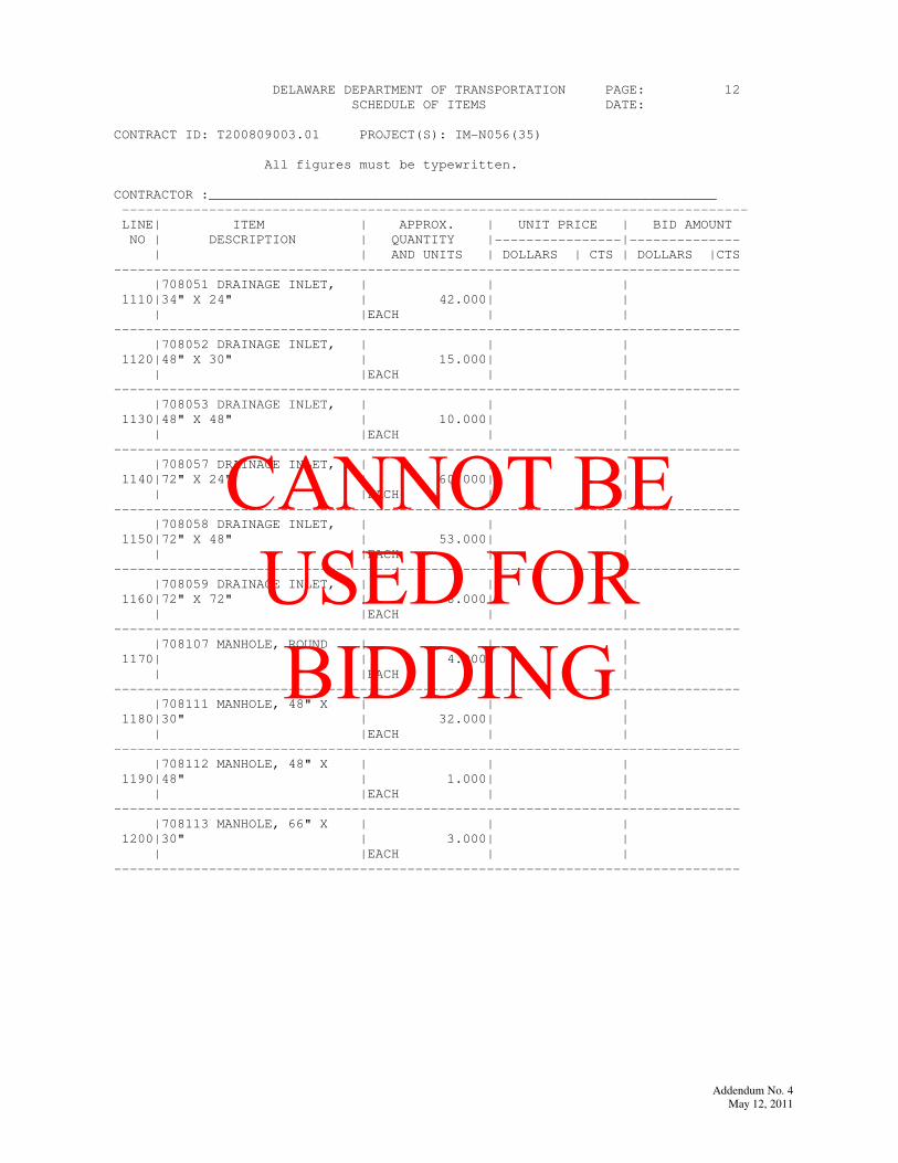
DELAWARE DEPARTMENT OF TRANSPORTATION PAGE: 12
SCHEDULE OF ITEMS DATE:
CONTRACT ID: T200809003.01 PROJECT(S): IM-N056(35)
All figures must be typewritten.
CONTRACTOR :________________________________________________________________
-------------------------------------------------------------------------------
LINE| ITEM | APPROX. | UNIT PRICE | BID AMOUNT
NO | DESCRIPTION | QUANTITY |----------------|--------------
| | AND UNITS | DOLLARS | CTS | DOLLARS |CTS
-------------------------------------------------------------------------------
|708051 DRAINAGE INLET, | | |
1110|34" X 24" | 42.000| |
| |EACH | |
-------------------------------------------------------------------------------
|708052 DRAINAGE INLET, | | |
1120|48" X 30" | 15.000| |
| |EACH | |
-------------------------------------------------------------------------------
|708053 DRAINAGE INLET, | | |
1130|48" X 48" | 10.000| |
| |EACH | |
-------------------------------------------------------------------------------
|708057 DRAINAGE INLET, | | |
1140|72" X 24" | 60.000| |
| |EACH | |
-------------------------------------------------------------------------------
|708058 DRAINAGE INLET, | | |
1150|72" X 48" | 53.000| |
| |EACH | |
-------------------------------------------------------------------------------
|708059 DRAINAGE INLET, | | |
1160|72" X 72" | 8.000| |
| |EACH | |
-------------------------------------------------------------------------------
|708107 MANHOLE, ROUND | | |
1170| | 4.000| |
| |EACH | |
-------------------------------------------------------------------------------
|708111 MANHOLE, 48" X | | |
1180|30" | 32.000| |
| |EACH | |
-------------------------------------------------------------------------------
|708112 MANHOLE, 48" X | | |
1190|48" | 1.000| |
| |EACH | |
-------------------------------------------------------------------------------
|708113 MANHOLE, 66" X | | |
1200|30" | 3.000| |
| |EACH | |
-------------------------------------------------------------------------------
Addendum No. 4
May 12, 2011
CANNOT BE USED FOR BIDDING

Addendum No. 4
May 12, 2011
CANNOT BE USED FOR BIDDING

DELAWARE DEPARTMENT OF TRANSPORTATION PAGE: 13
SCHEDULE OF ITEMS DATE:
CONTRACT ID: T200809003.01 PROJECT(S): IM-N056(35)
All figures must be typewritten.
CONTRACTOR :________________________________________________________________
-------------------------------------------------------------------------------
LINE| ITEM | APPROX. | UNIT PRICE | BID AMOUNT
NO | DESCRIPTION | QUANTITY |----------------|--------------
| | AND UNITS | DOLLARS | CTS | DOLLARS |CTS
-------------------------------------------------------------------------------
|708115 MANHOLE, 66" X | | |
1210|66" | 1.000| |
| |EACH | |
-------------------------------------------------------------------------------
|708500 REPLACING CATCH | | |
1220|BASIN GRATES | 5.000| |
| |EACH | |
-------------------------------------------------------------------------------
|708504 REPLACING CATCH | | |
1230|BASIN FRAMES | 5.000| |
| |EACH | |
-------------------------------------------------------------------------------
|708512 DRAINAGE INLET, | | |
1240|SPECIAL I | 1.000| |
| |EACH | |
-------------------------------------------------------------------------------
|708513 DRAINAGE INLET, | | |
1250|SPECIAL II | 8.000| |
| |EACH | |
-------------------------------------------------------------------------------
|708515 DRAINAGE INLET, | | |
1260|SPECIAL IV | 2.000| |
| |EACH | |
-------------------------------------------------------------------------------
|708516 DRAINAGE INLET, | | |
1270|SPECIAL V | 1.000| |
| |EACH | |
-------------------------------------------------------------------------------
|708517 DRAINAGE INLET, | | |
1280|SPECIAL VI | 2.000| |
| |EACH | |
-------------------------------------------------------------------------------
|708518 DRAINAGE INLET, | | |
1290|SPECIAL VII | 2.000| |
| |EACH | |
-------------------------------------------------------------------------------
|708537 REMOVE CATCH | | |
1300|BASIN | 14.000| |
| |EACH | |
-------------------------------------------------------------------------------
Addendum No. 4
May 12, 2011
CANNOT BE USED FOR BIDDING

Addendum No. 4
May 12, 2011
CANNOT BE USED FOR BIDDING
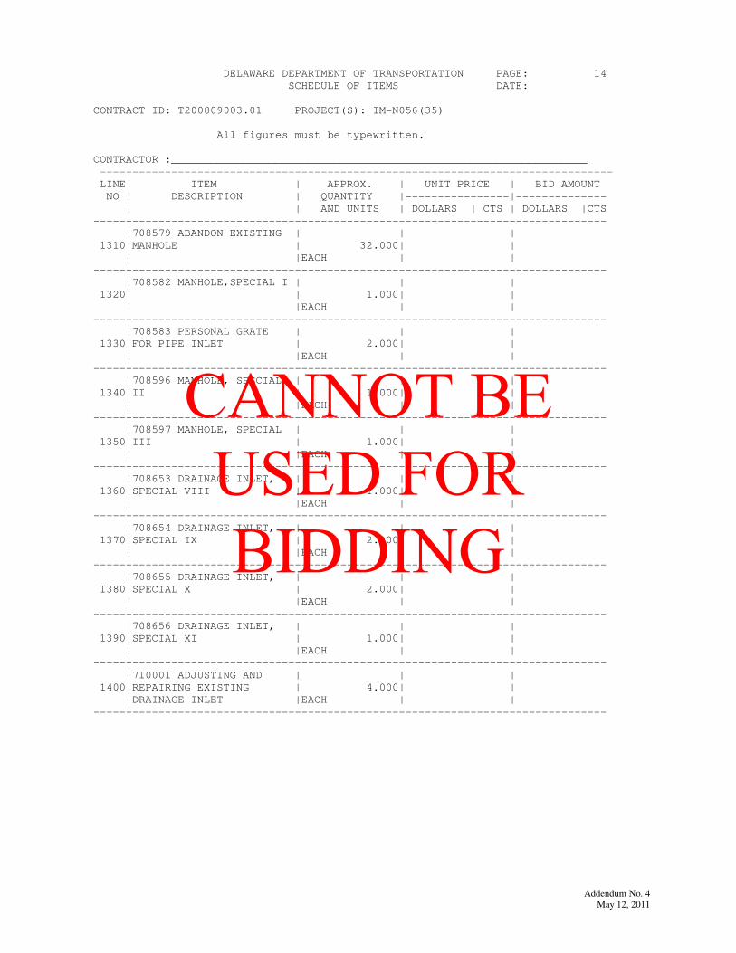
DELAWARE DEPARTMENT OF TRANSPORTATION PAGE: 14
SCHEDULE OF ITEMS DATE:
CONTRACT ID: T200809003.01 PROJECT(S): IM-N056(35)
All figures must be typewritten.
CONTRACTOR :________________________________________________________________
-------------------------------------------------------------------------------
LINE| ITEM | APPROX. | UNIT PRICE | BID AMOUNT
NO | DESCRIPTION | QUANTITY |----------------|--------------
| | AND UNITS | DOLLARS | CTS | DOLLARS |CTS
-------------------------------------------------------------------------------
|708579 ABANDON EXISTING | | |
1310|MANHOLE | 32.000| |
| |EACH | |
-------------------------------------------------------------------------------
|708582 MANHOLE,SPECIAL I | | |
1320| | 1.000| |
| |EACH | |
-------------------------------------------------------------------------------
|708583 PERSONAL GRATE | | |
1330|FOR PIPE INLET | 2.000| |
| |EACH | |
-------------------------------------------------------------------------------
|708596 MANHOLE, SPECIAL | | |
1340|II | 1.000| |
| |EACH | |
-------------------------------------------------------------------------------
|708597 MANHOLE, SPECIAL | | |
1350|III | 1.000| |
| |EACH | |
-------------------------------------------------------------------------------
|708653 DRAINAGE INLET, | | |
1360|SPECIAL VIII | 1.000| |
| |EACH | |
-------------------------------------------------------------------------------
|708654 DRAINAGE INLET, | | |
1370|SPECIAL IX | 2.000| |
| |EACH | |
-------------------------------------------------------------------------------
|708655 DRAINAGE INLET, | | |
1380|SPECIAL X | 2.000| |
| |EACH | |
-------------------------------------------------------------------------------
|708656 DRAINAGE INLET, | | |
1390|SPECIAL XI | 1.000| |
| |EACH | |
-------------------------------------------------------------------------------
|710001 ADJUSTING AND | | |
1400|REPAIRING EXISTING | 4.000| |
|DRAINAGE INLET |EACH | |
-------------------------------------------------------------------------------
Addendum No. 4
May 12, 2011
CANNOT BE USED FOR BIDDING

Addendum No. 4
May 12, 2011
CANNOT BE USED FOR BIDDING
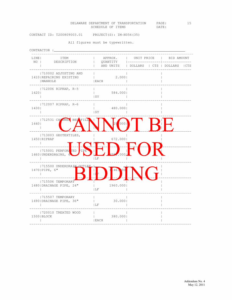
DELAWARE DEPARTMENT OF TRANSPORTATION PAGE: 15
SCHEDULE OF ITEMS DATE:
CONTRACT ID: T200809003.01 PROJECT(S): IM-N056(35)
All figures must be typewritten.
CONTRACTOR :________________________________________________________________
-------------------------------------------------------------------------------
LINE| ITEM | APPROX. | UNIT PRICE | BID AMOUNT
NO | DESCRIPTION | QUANTITY |----------------|--------------
| | AND UNITS | DOLLARS | CTS | DOLLARS |CTS
-------------------------------------------------------------------------------
|710002 ADJUSTING AND | | |
1410|REPAIRING EXISTING | 2.000| |
|MANHOLE |EACH | |
-------------------------------------------------------------------------------
|712006 RIPRAP, R-5 | | |
1420| | 584.000| |
| |SY | |
-------------------------------------------------------------------------------
|712007 RIPRAP, R-6 | | |
1430| | 480.000| |
| |SY | |
-------------------------------------------------------------------------------
|712531 CHANNEL BED FILL | | |
1440| | 29.000| |
| |CY | |
-------------------------------------------------------------------------------
|713003 GEOTEXTILES, | | |
1450|RIPRAP | 672.000| |
| |SY | |
-------------------------------------------------------------------------------
|715001 PERFORATED PIPE | | |
1460|UNDERDRAINS, 6" | 49552.000| |
| |LF | |
-------------------------------------------------------------------------------
|715500 UNDERDRAIN OUTLET | | |
1470|PIPE, 6" | 1146.000| |
| |LF | |
-------------------------------------------------------------------------------
|715506 TEMPORARY | | |
1480|DRAINAGE PIPE, 24" | 1960.000| |
| |LF | |
-------------------------------------------------------------------------------
|715507 TEMPORARY | | |
1490|DRAINAGE PIPE, 36" | 30.000| |
| |LF | |
-------------------------------------------------------------------------------
|720010 TREATED WOOD | | |
1500|BLOCK | 380.000| |
| |EACH | |
-------------------------------------------------------------------------------
Addendum No. 4
May 12, 2011
CANNOT BE USED FOR BIDDING

Addendum No. 4
May 12, 2011
CANNOT BE USED FOR BIDDING
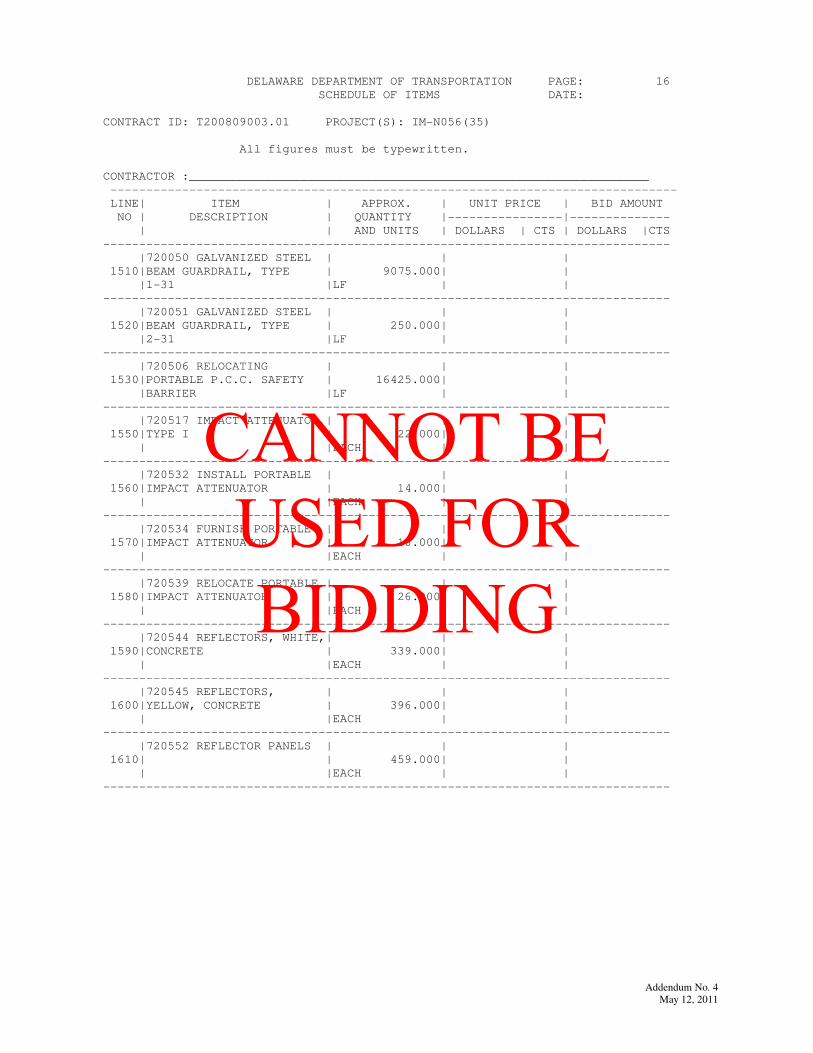
DELAWARE DEPARTMENT OF TRANSPORTATION PAGE: 16
SCHEDULE OF ITEMS DATE:
CONTRACT ID: T200809003.01 PROJECT(S): IM-N056(35)
All figures must be typewritten.
CONTRACTOR :________________________________________________________________
-------------------------------------------------------------------------------
LINE| ITEM | APPROX. | UNIT PRICE | BID AMOUNT
NO | DESCRIPTION | QUANTITY |----------------|--------------
| | AND UNITS | DOLLARS | CTS | DOLLARS |CTS
-------------------------------------------------------------------------------
|720050 GALVANIZED STEEL | | |
1510|BEAM GUARDRAIL, TYPE | 9075.000| |
|1-31 |LF | |
-------------------------------------------------------------------------------
|720051 GALVANIZED STEEL | | |
1520|BEAM GUARDRAIL, TYPE | 250.000| |
|2-31 |LF | |
-------------------------------------------------------------------------------
|720506 RELOCATING | | |
1530|PORTABLE P.C.C. SAFETY | 16425.000| |
|BARRIER |LF | |
-------------------------------------------------------------------------------
|720517 IMPACT ATTENUATOR,| | |
1550|TYPE I | 22.000| |
| |EACH | |
-------------------------------------------------------------------------------
|720532 INSTALL PORTABLE | | |
1560|IMPACT ATTENUATOR | 14.000| |
| |EACH | |
-------------------------------------------------------------------------------
|720534 FURNISH PORTABLE | | |
1570|IMPACT ATTENUATOR | 16.000| |
| |EACH | |
-------------------------------------------------------------------------------
|720539 RELOCATE PORTABLE | | |
1580|IMPACT ATTENUATOR | 26.000| |
| |EACH | |
-------------------------------------------------------------------------------
|720544 REFLECTORS, WHITE,| | |
1590|CONCRETE | 339.000| |
| |EACH | |
-------------------------------------------------------------------------------
|720545 REFLECTORS, | | |
1600|YELLOW, CONCRETE | 396.000| |
| |EACH | |
-------------------------------------------------------------------------------
|720552 REFLECTOR PANELS | | |
1610| | 459.000| |
| |EACH | |
-------------------------------------------------------------------------------
Addendum No. 4
May 12, 2011
CANNOT BE USED FOR BIDDING

Addendum No. 4
May 12, 2011
CANNOT BE USED FOR BIDDING
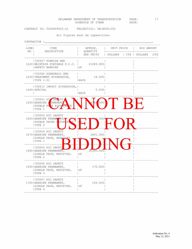
DELAWARE DEPARTMENT OF TRANSPORTATION PAGE: 17
SCHEDULE OF ITEMS DATE:
CONTRACT ID: T200809003.01 PROJECT(S): IM-N056(35)
All figures must be typewritten.
CONTRACTOR :________________________________________________________________
-------------------------------------------------------------------------------
LINE| ITEM | APPROX. | UNIT PRICE | BID AMOUNT
NO | DESCRIPTION | QUANTITY |----------------|--------------
| | AND UNITS | DOLLARS | CTS | DOLLARS |CTS
-------------------------------------------------------------------------------
|720567 FURNISH AND | | |
1620|MAINTAIN PORTABLE P.C.C. | 21089.000| |
|SAFETY BARRIER |LF | |
-------------------------------------------------------------------------------
|720585 GUARDRAIL END | | |
1630|TREATMENT ATTENUATOR, | 18.000| |
|TYPE 1-31 |EACH | |
-------------------------------------------------------------------------------
|720612 IMPACT ATTENUATOR,| | |
1640|SPECIAL | 5.000| |
| |EACH | |
-------------------------------------------------------------------------------
|720651 PCC SAFETY | | |
1650|BARRIER PERMANENT, | 6549.000| |
|DOUBLE FACE BIFURCATED |LF | |
|TYPE I | | |
-------------------------------------------------------------------------------
|720652 PCC SAFETY | | |
1660|BARRIER PERMANENT, | 616.000| |
|DOUBLE FACED BIFURCATED |LF | |
|TYPE 2 | | |
-------------------------------------------------------------------------------
|720654 PCC SAFETY | | |
1670|BARRIER PERMANENT, | 2891.000| |
|SINGLE FACE, MODIFIED |LF | |
|TYPE I | | |
-------------------------------------------------------------------------------
|720655 PCC SAFETY | | |
1680|BARRIER PERMANENT, | 20380.000| |
|SINGLE FACE, MODIFIED, |LF | |
|TYPE 2 | | |
-------------------------------------------------------------------------------
|720656 PCC SAFETY | | |
1690|BARRIER PERMANENT, | 170.000| |
|SINGLE FACE, MODIFIED, |LF | |
|TYPE 3 | | |
-------------------------------------------------------------------------------
|720657 PCC SAFETY | | |
1700|BARRIER PERMANENT, | 199.000| |
|SINGLE FACE, MODIFIED, |LF | |
|TYPE 4 | | |
-------------------------------------------------------------------------------
Addendum No. 4
May 12, 2011
CANNOT BE USED FOR BIDDING

Addendum No. 4
May 12, 2011
CANNOT BE USED FOR BIDDING
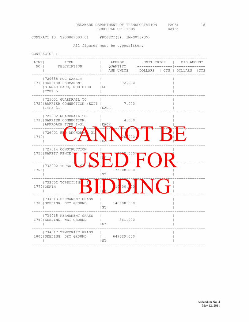
DELAWARE DEPARTMENT OF TRANSPORTATION PAGE: 18
SCHEDULE OF ITEMS DATE:
CONTRACT ID: T200809003.01 PROJECT(S): IM-N056(35)
All figures must be typewritten.
CONTRACTOR :________________________________________________________________
-------------------------------------------------------------------------------
LINE| ITEM | APPROX. | UNIT PRICE | BID AMOUNT
NO | DESCRIPTION | QUANTITY |----------------|--------------
| | AND UNITS | DOLLARS | CTS | DOLLARS |CTS
-------------------------------------------------------------------------------
|720658 PCC SAFETY | | |
1710|BARRIER PERMANENT, | 72.000| |
|SINGLE FACE, MODIFIED |LF | |
|TYPE 5 | | |
-------------------------------------------------------------------------------
|725001 GUARDRAIL TO | | |
1720|BARRIER CONNECTION (EXIT | 7.000| |
|TYPE 31) |EACH | |
-------------------------------------------------------------------------------
|725002 GUARDRAIL TO | | |
1730|BARRIER CONNECTION, | 4.000| |
|APPROACH TYPE 1-31 |EACH | |
-------------------------------------------------------------------------------
|726001 END ANCHORAGE 31 | | |
1740| | 20.000| |
| |EACH | |
-------------------------------------------------------------------------------
|727014 CONSTRUCTION | | |
1750|SAFETY FENCE | 7000.000| |
| |LF | |
-------------------------------------------------------------------------------
|732002 TOPSOIL, 6" DEPTH | | |
1760| | 135908.000| |
| |SY | |
-------------------------------------------------------------------------------
|733002 TOPSOILING, 6" | | |
1770|DEPTH | 10900.000| |
| |SY | |
-------------------------------------------------------------------------------
|734013 PERMANENT GRASS | | |
1780|SEEDING, DRY GROUND | 146608.000| |
| |SY | |
-------------------------------------------------------------------------------
|734015 PERMANENT GRASS | | |
1790|SEEDING, WET GROUND | 361.000| |
| |SY | |
-------------------------------------------------------------------------------
|734017 TEMPORARY GRASS | | |
1800|SEEDING, DRY GROUND | 649329.000| |
| |SY | |
-------------------------------------------------------------------------------
Addendum No. 4
May 12, 2011
CANNOT BE USED FOR BIDDING

Addendum No. 4
May 12, 2011
CANNOT BE USED FOR BIDDING
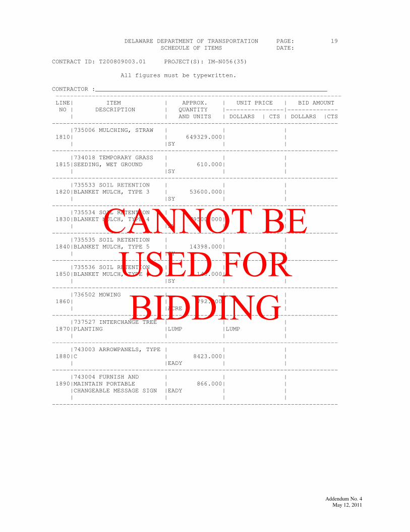
DELAWARE DEPARTMENT OF TRANSPORTATION PAGE: 19
SCHEDULE OF ITEMS DATE:
CONTRACT ID: T200809003.01 PROJECT(S): IM-N056(35)
All figures must be typewritten.
CONTRACTOR :________________________________________________________________
-------------------------------------------------------------------------------
LINE| ITEM | APPROX. | UNIT PRICE | BID AMOUNT
NO | DESCRIPTION | QUANTITY |----------------|--------------
| | AND UNITS | DOLLARS | CTS | DOLLARS |CTS
-------------------------------------------------------------------------------
|735006 MULCHING, STRAW | | |
1810| | 649329.000| |
| |SY | |
-------------------------------------------------------------------------------
|734018 TEMPORARY GRASS | | |
1815|SEEDING, WET GROUND | 610.000| |
| |SY | |
-------------------------------------------------------------------------------
|735533 SOIL RETENTION | | |
1820|BLANKET MULCH, TYPE 3 | 53600.000| |
| |SY | |
-------------------------------------------------------------------------------
|735534 SOIL RETENTION | | |
1830|BLANKET MULCH, TYPE 4 | 79500.000| |
| |SY | |
-------------------------------------------------------------------------------
|735535 SOIL RETENTION | | |
1840|BLANKET MULCH, TYPE 5 | 14398.000| |
| |SY | |
-------------------------------------------------------------------------------
|735536 SOIL RETENTION | | |
1850|BLANKET MULCH, TYPE 6 | 143.000| |
| |SY | |
-------------------------------------------------------------------------------
|736502 MOWING | | |
1860| | 792.000| |
| |ACRE | |
-------------------------------------------------------------------------------
|737527 INTERCHANGE TREE | | |
1870|PLANTING |LUMP |LUMP |
| | | |
-------------------------------------------------------------------------------
|743003 ARROWPANELS, TYPE | | |
1880|C | 8423.000| |
| |EADY | |
-------------------------------------------------------------------------------
|743004 FURNISH AND | | |
1890|MAINTAIN PORTABLE | 866.000| |
|CHANGEABLE MESSAGE SIGN |EADY | |
| | | |
-------------------------------------------------------------------------------
Addendum No. 4
May 12, 2011
CANNOT BE USED FOR BIDDING

Addendum No. 4
May 12, 2011
CANNOT BE USED FOR BIDDING
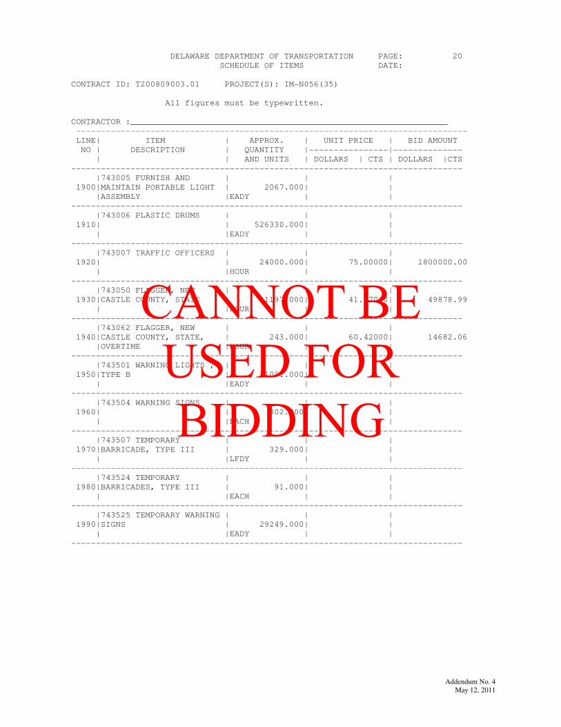
DELAWARE DEPARTMENT OF TRANSPORTATION PAGE: 20
SCHEDULE OF ITEMS DATE:
CONTRACT ID: T200809003.01 PROJECT(S): IM-N056(35)
All figures must be typewritten.
CONTRACTOR :________________________________________________________________
-------------------------------------------------------------------------------
LINE| ITEM | APPROX. | UNIT PRICE | BID AMOUNT
NO | DESCRIPTION | QUANTITY |----------------|--------------
| | AND UNITS | DOLLARS | CTS | DOLLARS |CTS
-------------------------------------------------------------------------------
|743005 FURNISH AND | | |
1900|MAINTAIN PORTABLE LIGHT | 2067.000| |
|ASSEMBLY |EADY | |
-------------------------------------------------------------------------------
|743006 PLASTIC DRUMS | | |
1910| | 526330.000| |
| |EADY | |
-------------------------------------------------------------------------------
|743007 TRAFFIC OFFICERS | | |
1920| | 24000.000| 75.00000| 1800000.00
| |HOUR | |
-------------------------------------------------------------------------------
|743050 FLAGGER, NEW | | |
1930|CASTLE COUNTY, STATE | 1197.000| 41.67000| 49878.99
| |HOUR | |
-------------------------------------------------------------------------------
|743062 FLAGGER, NEW | | |
1940|CASTLE COUNTY, STATE, | 243.000| 60.42000| 14682.06
|OVERTIME |HOUR | |
-------------------------------------------------------------------------------
|743501 WARNING LIGHTS , | | |
1950|TYPE B | 11091.000| |
| |EADY | |
-------------------------------------------------------------------------------
|743504 WARNING SIGNS | | |
1960| | 802.000| |
| |EACH | |
-------------------------------------------------------------------------------
|743507 TEMPORARY | | |
1970|BARRICADE, TYPE III | 329.000| |
| |LFDY | |
-------------------------------------------------------------------------------
|743524 TEMPORARY | | |
1980|BARRICADES, TYPE III | 91.000| |
| |EACH | |
-------------------------------------------------------------------------------
|743525 TEMPORARY WARNING | | |
1990|SIGNS | 29249.000| |
| |EADY | |
-------------------------------------------------------------------------------
Addendum No. 4
May 12, 2011
CANNOT BE USED FOR BIDDING

Addendum No. 4
May 12, 2011
CANNOT BE USED FOR BIDDING
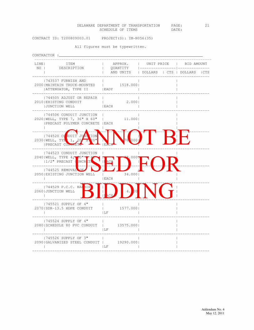
DELAWARE DEPARTMENT OF TRANSPORTATION PAGE: 21
SCHEDULE OF ITEMS DATE:
CONTRACT ID: T200809003.01 PROJECT(S): IM-N056(35)
All figures must be typewritten.
CONTRACTOR :________________________________________________________________
-------------------------------------------------------------------------------
LINE| ITEM | APPROX. | UNIT PRICE | BID AMOUNT
NO | DESCRIPTION | QUANTITY |----------------|--------------
| | AND UNITS | DOLLARS | CTS | DOLLARS |CTS
-------------------------------------------------------------------------------
|743537 FURNISH AND | | |
2000|MAINTAIN TRUCK-MOUNTED | 1518.000| |
|ATTENUATOR, TYPE II |EADY | |
-------------------------------------------------------------------------------
|744505 ADJUST OR REPAIR | | |
2010|EXISTING CONDUIT | 2.000| |
|JUNCTION WELL |EACH | |
-------------------------------------------------------------------------------
|744506 CONDUIT JUNCTION | | |
2020|WELL, TYPE 7, 36" X 60" | 11.000| |
|PRECAST POLYMER CONCRETE |EACH | |
| | | |
-------------------------------------------------------------------------------
|744520 CONDUIT JUNCTION | | |
2030|WELL, TYPE 1, 20" X 20" | 76.000| |
|PRECAST CONCRETE |EACH | |
-------------------------------------------------------------------------------
|744523 CONDUIT JUNCTION | | |
2040|WELL, TYPE 4, 20" X 42 | 38.000| |
|1/2" PRECAST CONCRETE |EACH | |
-------------------------------------------------------------------------------
|744525 REMOVAL OF | | |
2050|EXISTING JUNCTION WELL | 34.000| |
| |EACH | |
-------------------------------------------------------------------------------
|744529 P.C.C. BARRIER | | |
2060|JUNCTION WELL | 4.000| |
| |EACH | |
-------------------------------------------------------------------------------
|745521 SUPPLY OF 4" | | |
2070|SDR-13.5 HDPE CONDUIT | 1577.000| |
| |LF | |
-------------------------------------------------------------------------------
|745524 SUPPLY OF 4" | | |
2080|SCHEDULE 80 PVC CONDUIT | 13575.000| |
| |LF | |
-------------------------------------------------------------------------------
|745526 SUPPLY OF 3" | | |
2090|GALVANIZED STEEL CONDUIT | 19290.000| |
| |LF | |
-------------------------------------------------------------------------------
Addendum No. 4
May 12, 2011
CANNOT BE USED FOR BIDDING

Addendum No. 4
May 12, 2011
CANNOT BE USED FOR BIDDING
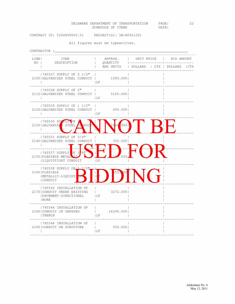
DELAWARE DEPARTMENT OF TRANSPORTATION PAGE: 22
SCHEDULE OF ITEMS DATE:
CONTRACT ID: T200809003.01 PROJECT(S): IM-N056(35)
All figures must be typewritten.
CONTRACTOR :________________________________________________________________
-------------------------------------------------------------------------------
LINE| ITEM | APPROX. | UNIT PRICE | BID AMOUNT
NO | DESCRIPTION | QUANTITY |----------------|--------------
| | AND UNITS | DOLLARS | CTS | DOLLARS |CTS
-------------------------------------------------------------------------------
|745527 SUPPLY OF 2 1/2" | | |
2100|GALVANIZED STEEL CONDUIT | 1595.000| |
| |LF | |
-------------------------------------------------------------------------------
|745528 SUPPLY OF 2" | | |
2110|GALVANIZED STEEL CONDUIT | 5165.000| |
| |LF | |
-------------------------------------------------------------------------------
|745529 SUPPLY OF 1 1/2" | | |
2120|GALVANIZED STEEL CONDUIT | 290.000| |
| |LF | |
-------------------------------------------------------------------------------
|745530 SUPPLY OF 1" | | |
2130|GALVANIZED STEEL CONDUIT | 1065.000| |
| |LF | |
-------------------------------------------------------------------------------
|745531 SUPPLY OF 3/4" | | |
2140|GALVANIZED STEEL CONDUIT | 350.000| |
| |LF | |
-------------------------------------------------------------------------------
|745537 SUPPLY OF 3/4" | | |
2150|FLEXIBLE METALLIC- | 105.000| |
|LIQUIDTIGHT CONDUIT |LF | |
-------------------------------------------------------------------------------
|745538 SUPPLY OF 1 1/2" | | |
2160|FLEXIBLE | 555.000| |
|METALLIC-LIQUIDTIGHT |LF | |
|CONDUIT | | |
-------------------------------------------------------------------------------
|745542 INSTALLATION OF | | |
2170|CONDUIT UNDER EXISTING | 3272.000| |
|PAVEMENT-DIRECTIONAL |LF | |
|BORE | | |
-------------------------------------------------------------------------------
|745544 INSTALLATION OF | | |
2180|CONDUIT IN UNPAVED | 16295.000| |
|TRENCH |LF | |
-------------------------------------------------------------------------------
|745546 INSTALLATION OF | | |
2190|CONDUIT ON STRUCTURE | 555.000| |
| |LF | |
-------------------------------------------------------------------------------
Addendum No. 4
May 12, 2011
CANNOT BE USED FOR BIDDING

Addendum No. 4
May 12, 2011
CANNOT BE USED FOR BIDDING
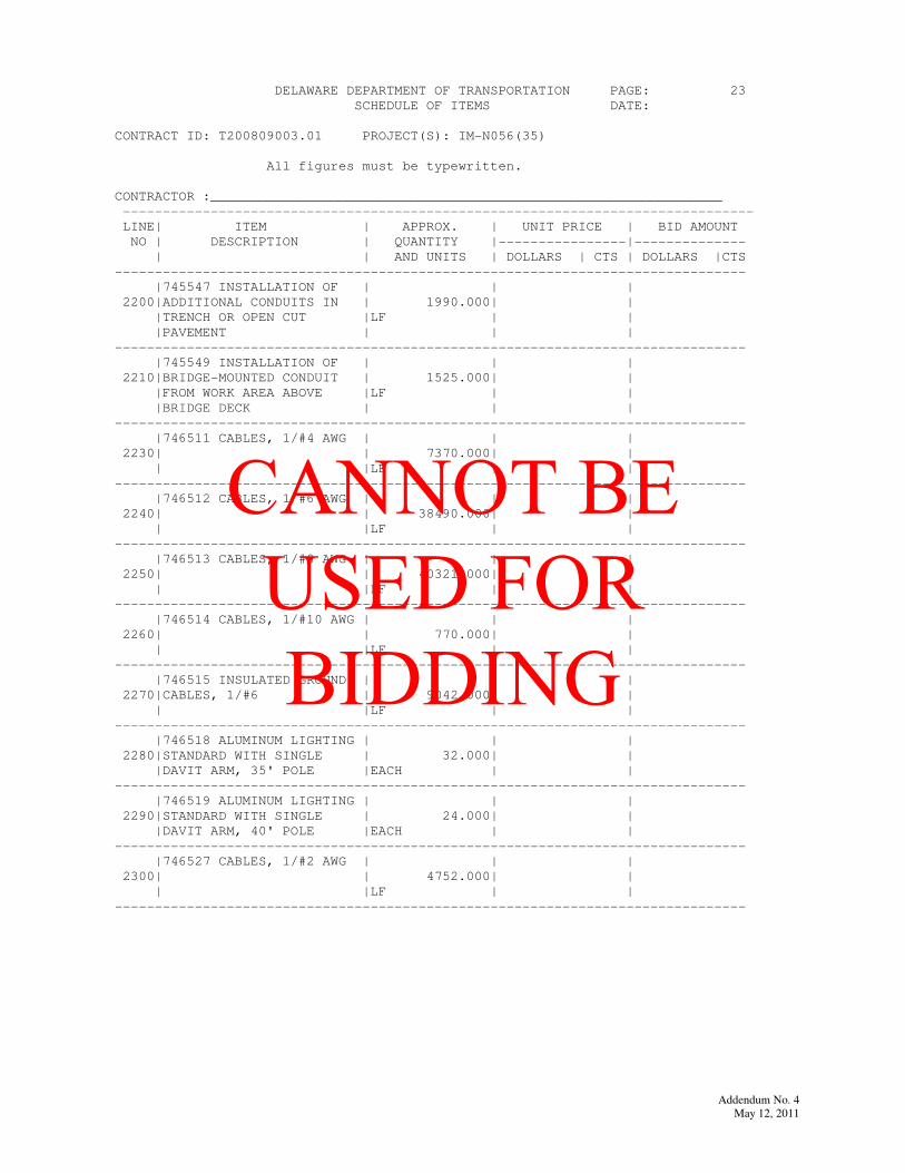
DELAWARE DEPARTMENT OF TRANSPORTATION PAGE: 23
SCHEDULE OF ITEMS DATE:
CONTRACT ID: T200809003.01 PROJECT(S): IM-N056(35)
All figures must be typewritten.
CONTRACTOR :________________________________________________________________
-------------------------------------------------------------------------------
LINE| ITEM | APPROX. | UNIT PRICE | BID AMOUNT
NO | DESCRIPTION | QUANTITY |----------------|--------------
| | AND UNITS | DOLLARS | CTS | DOLLARS |CTS
-------------------------------------------------------------------------------
|745547 INSTALLATION OF | | |
2200|ADDITIONAL CONDUITS IN | 1990.000| |
|TRENCH OR OPEN CUT |LF | |
|PAVEMENT | | |
-------------------------------------------------------------------------------
|745549 INSTALLATION OF | | |
2210|BRIDGE-MOUNTED CONDUIT | 1525.000| |
|FROM WORK AREA ABOVE |LF | |
|BRIDGE DECK | | |
-------------------------------------------------------------------------------
|746511 CABLES, 1/#4 AWG | | |
2230| | 7370.000| |
| |LF | |
-------------------------------------------------------------------------------
|746512 CABLES, 1/#6 AWG | | |
2240| | 38490.000| |
| |LF | |
-------------------------------------------------------------------------------
|746513 CABLES, 1/#8 AWG | | |
2250| | 40321.000| |
| |LF | |
-------------------------------------------------------------------------------
|746514 CABLES, 1/#10 AWG | | |
2260| | 770.000| |
| |LF | |
-------------------------------------------------------------------------------
|746515 INSULATED GROUND | | |
2270|CABLES, 1/#6 | 9042.000| |
| |LF | |
-------------------------------------------------------------------------------
|746518 ALUMINUM LIGHTING | | |
2280|STANDARD WITH SINGLE | 32.000| |
|DAVIT ARM, 35' POLE |EACH | |
-------------------------------------------------------------------------------
|746519 ALUMINUM LIGHTING | | |
2290|STANDARD WITH SINGLE | 24.000| |
|DAVIT ARM, 40' POLE |EACH | |
-------------------------------------------------------------------------------
|746527 CABLES, 1/#2 AWG | | |
2300| | 4752.000| |
| |LF | |
-------------------------------------------------------------------------------
Addendum No. 4
May 12, 2011
CANNOT BE USED FOR BIDDING

Addendum No. 4
May 12, 2011
CANNOT BE USED FOR BIDDING

DELAWARE DEPARTMENT OF TRANSPORTATION PAGE: 24
SCHEDULE OF ITEMS DATE:
CONTRACT ID: T200809003.01 PROJECT(S): IM-N056(35)
All figures must be typewritten.
CONTRACTOR :________________________________________________________________
-------------------------------------------------------------------------------
LINE| ITEM | APPROX. | UNIT PRICE | BID AMOUNT
NO | DESCRIPTION | QUANTITY |----------------|--------------
| | AND UNITS | DOLLARS | CTS | DOLLARS |CTS
-------------------------------------------------------------------------------
|746537 RELOCATING | | |
2320|EXISTING LIGHT STANDARDS | 2.000| |
| |EACH | |
-------------------------------------------------------------------------------
|746552 FURNISH AND | | |
2330|MAINTAIN TEMPORARY |LUMP |LUMP |
|LIGHTING | | |
-------------------------------------------------------------------------------
|746564 INSULATED GROUND | | |
2340|CABLES, 1/#4 | 1795.000| |
| |LF | |
-------------------------------------------------------------------------------
|746577 INSULATED GROUND | | |
2350|CABLE, 1/#8 | 11055.000| |
| |LF | |
-------------------------------------------------------------------------------
|746592 REPLACE/ADAPT | | |
2360|EXISTING TRANSFORMER | 2.000| |
|BASE |EACH | |
-------------------------------------------------------------------------------
|746594 LUMINAIRE (HPS), | | |
2370|250 WATT | 4.000| |
| |EACH | |
-------------------------------------------------------------------------------
|746596 JUNCTION BOX ON | | |
2380|STRUCTURE | 9.000| |
| |EACH | |
-------------------------------------------------------------------------------
|746598 INSULATED GROUND | | |
2390|CABLE , 1/#2 | 1717.000| |
| |LF | |
-------------------------------------------------------------------------------
|746605 INSULATED GROUND | | |
2400|CABLE, 1/#10 | 386.000| |
| |LF | |
-------------------------------------------------------------------------------
|746620 RELOCATION OF | | |
2410|EXISTING LIGHTING TOWER | 1.000| |
| |EACH | |
-------------------------------------------------------------------------------
Addendum No. 4
May 12, 2011
CANNOT BE USED FOR BIDDING

Addendum No. 4
May 12, 2011
CANNOT BE USED FOR BIDDING

DELAWARE DEPARTMENT OF TRANSPORTATION PAGE: 25
SCHEDULE OF ITEMS DATE:
CONTRACT ID: T200809003.01 PROJECT(S): IM-N056(35)
All figures must be typewritten.
CONTRACTOR :________________________________________________________________
-------------------------------------------------------------------------------
LINE| ITEM | APPROX. | UNIT PRICE | BID AMOUNT
NO | DESCRIPTION | QUANTITY |----------------|--------------
| | AND UNITS | DOLLARS | CTS | DOLLARS |CTS
-------------------------------------------------------------------------------
|746621 LIGHTING TOWER | | |
2420|AND INSTALLATION | 7.000| |
| |EACH | |
-------------------------------------------------------------------------------
|746622 CABLES, 1/#4/0 | | |
2430|AWG | 340.000| |
| |LF | |
-------------------------------------------------------------------------------
|746653 ELECTRICAL | | |
2440|TESTING |LUMP |LUMP |
| | | |
-------------------------------------------------------------------------------
|746716 ELECTRIC SERVICE | | |
2450|ON PEDESTAL | 2.000| |
| |EACH | |
-------------------------------------------------------------------------------
|746774 SUPPLY AND | | |
2480|INSTALLATION OF LOOP | 1210.000| |
|DETECTOR WIRE |LF | |
-------------------------------------------------------------------------------
|746787 REMOVAL OF CABLE | | |
2490|FROM CONDUIT OR POLE | 1300.000| |
| |LF | |
-------------------------------------------------------------------------------
|746811 INSTALLATION OR | | |
2500|REMOVAL OF LIGHTINGPOLE | 32.000| |
|W/ MAST ARM |EACH | |
-------------------------------------------------------------------------------
|746816 REMOVAL OF | | |
2510|LUMINAIRE | 36.000| |
| |EACH | |
-------------------------------------------------------------------------------
|746830 REMOVAL OF | | |
2520|CONCRETE POLE BASES AND | 19.000| |
|CABINET FOUNDATIONS |CY | |
-------------------------------------------------------------------------------
|746847 POLE BASE, TYPE 3 | | |
2530| | 8.000| |
| |EACH | |
-------------------------------------------------------------------------------
Addendum No. 4
May 12, 2011
CANNOT BE USED FOR BIDDING

Addendum No. 4
May 12, 2011
CANNOT BE USED FOR BIDDING
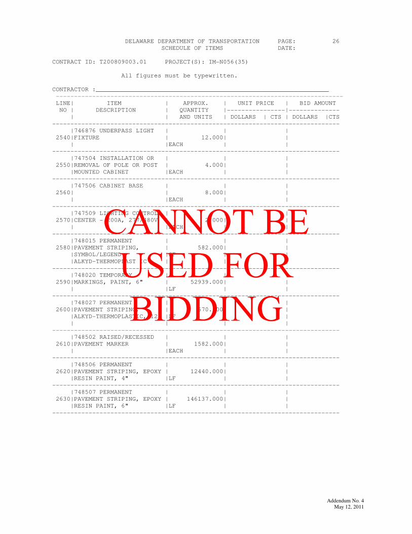
DELAWARE DEPARTMENT OF TRANSPORTATION PAGE: 26
SCHEDULE OF ITEMS DATE:
CONTRACT ID: T200809003.01 PROJECT(S): IM-N056(35)
All figures must be typewritten.
CONTRACTOR :________________________________________________________________
-------------------------------------------------------------------------------
LINE| ITEM | APPROX. | UNIT PRICE | BID AMOUNT
NO | DESCRIPTION | QUANTITY |----------------|--------------
| | AND UNITS | DOLLARS | CTS | DOLLARS |CTS
-------------------------------------------------------------------------------
|746876 UNDERPASS LIGHT | | |
2540|FIXTURE | 12.000| |
| |EACH | |
-------------------------------------------------------------------------------
|747504 INSTALLATION OR | | |
2550|REMOVAL OF POLE OR POST | 4.000| |
|MOUNTED CABINET |EACH | |
-------------------------------------------------------------------------------
|747506 CABINET BASE | | |
2560| | 8.000| |
| |EACH | |
-------------------------------------------------------------------------------
|747509 LIGHTING CONTROL | | |
2570|CENTER - 200A, 277/480V | 2.000| |
| |EACH | |
-------------------------------------------------------------------------------
|748015 PERMANENT | | |
2580|PAVEMENT STRIPING, | 582.000| |
|SYMBOL/LEGEND |SF | |
|ALKYD-THERMOPLAST IC | | |
-------------------------------------------------------------------------------
|748020 TEMPORARY | | |
2590|MARKINGS, PAINT, 6" | 52939.000| |
| |LF | |
-------------------------------------------------------------------------------
|748027 PERMANENT | | |
2600|PAVEMENT STRIPING, | 570.000| |
|ALKYD-THERMOPLASTIC, 12" |LF | |
| | | |
-------------------------------------------------------------------------------
|748502 RAISED/RECESSED | | |
2610|PAVEMENT MARKER | 1582.000| |
| |EACH | |
-------------------------------------------------------------------------------
|748506 PERMANENT | | |
2620|PAVEMENT STRIPING, EPOXY | 12440.000| |
|RESIN PAINT, 4" |LF | |
-------------------------------------------------------------------------------
|748507 PERMANENT | | |
2630|PAVEMENT STRIPING, EPOXY | 146137.000| |
|RESIN PAINT, 6" |LF | |
-------------------------------------------------------------------------------
Addendum No. 4
May 12, 2011
CANNOT BE USED FOR BIDDING

Addendum No. 4
May 12, 2011
CANNOT BE USED FOR BIDDING

DELAWARE DEPARTMENT OF TRANSPORTATION PAGE: 27
SCHEDULE OF ITEMS DATE:
CONTRACT ID: T200809003.01 PROJECT(S): IM-N056(35)
All figures must be typewritten.
CONTRACTOR :________________________________________________________________
-------------------------------------------------------------------------------
LINE| ITEM | APPROX. | UNIT PRICE | BID AMOUNT
NO | DESCRIPTION | QUANTITY |----------------|--------------
| | AND UNITS | DOLLARS | CTS | DOLLARS |CTS
-------------------------------------------------------------------------------
|748508 PERMANENT | | |
2640|PAVEMENT STRIPING, EPOXY | 340.000| |
|RESIN PAINT, 8" |LF | |
-------------------------------------------------------------------------------
|748509 PERMANENT | | |
2650|PAVEMENT STRIPING, EPOXY | 22410.000| |
|RESIN PAINT, 12" |LF | |
-------------------------------------------------------------------------------
|748526 TEMPORARY | | |
2660|MARKINGS, TAPE, 6" | 4950.000| |
| |LF | |
-------------------------------------------------------------------------------
|748530 REMOVAL OF | | |
2670|PAVEMENT STRIPING | 15125.000| |
| |SF | |
-------------------------------------------------------------------------------
|748539 PERMANENT | | |
2680|PAVEMENT STRIPING, EPOXY | 360.000| |
|RESIN PAINT, BLACK, 12" |LF | |
| | | |
-------------------------------------------------------------------------------
|748540 PERMANENT | | |
2690|PAVEMENT STRIPING, EPOXY | 100.000| |
|RESIN PAINT, BLACK, 16" |LF | |
| | | |
-------------------------------------------------------------------------------
|748547 RETROREFLECTIVE | | |
2700|PREFORMED PATTERNED | 390.000| |
|CONTRAST MARKINGS, 9" |LF | |
-------------------------------------------------------------------------------
|748557 PERMANENT | | |
2710|PAVEMENT STRIPING, EPOXY | 4200.000| |
|RESIN PAINT, BLACK, 3" |LF | |
-------------------------------------------------------------------------------
|749500 SIGN PANEL | | |
2720| | 23224.000| |
| |SF | |
-------------------------------------------------------------------------------
|749511 INSTALLATION OR | | |
2730|REMOVAL OF SIGN ON | 280.000| |
|ROADSIDE I-BEAM |SF | |
|STRUCTURE | | |
-------------------------------------------------------------------------------
Addendum No. 4
May 12, 2011
CANNOT BE USED FOR BIDDING

Addendum No. 4
May 12, 2011
CANNOT BE USED FOR BIDDING
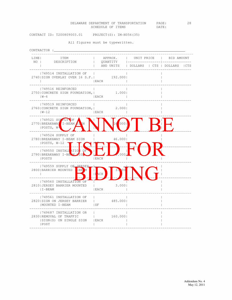
DELAWARE DEPARTMENT OF TRANSPORTATION PAGE: 28
SCHEDULE OF ITEMS DATE:
CONTRACT ID: T200809003.01 PROJECT(S): IM-N056(35)
All figures must be typewritten.
CONTRACTOR :________________________________________________________________
-------------------------------------------------------------------------------
LINE| ITEM | APPROX. | UNIT PRICE | BID AMOUNT
NO | DESCRIPTION | QUANTITY |----------------|--------------
| | AND UNITS | DOLLARS | CTS | DOLLARS |CTS
-------------------------------------------------------------------------------
|749514 INSTALLATION OF | | |
2740|SIGN OVERLAY OVER 16 S.F.| 192.000| |
| |EACH | |
-------------------------------------------------------------------------------
|749516 REINFORCED | | |
2750|CONCRETE SIGN FOUNDATION,| 1.000| |
|W-6 |EACH | |
-------------------------------------------------------------------------------
|749519 REINFORCED | | |
2760|CONCRETE SIGN FOUNDATION,| 2.000| |
|W-12 |EACH | |
-------------------------------------------------------------------------------
|749521 SUPPLY OF | | |
2770|BREAKAWAY I-BEAM SIGN | 16.000| |
|POSTS, W-6 |LF | |
-------------------------------------------------------------------------------
|749524 SUPPLY OF | | |
2780|BREAKAWAY I-BEAM SIGN | 46.000| |
|POSTS, W-12 |LF | |
-------------------------------------------------------------------------------
|749550 INSTALLATION OF | | |
2790|BREAKAWAY I-BEAM SIGN | 3.000| |
|POSTS |EACH | |
-------------------------------------------------------------------------------
|749559 SUPPLY OF JERSEY | | |
2800|BARRIER MOUNTED I-BEAM | 3.000| |
| |EACH | |
-------------------------------------------------------------------------------
|749560 INSTALLATION OF | | |
2810|JERSEY BARRIER MOUNTED | 3.000| |
|I-BEAM |EACH | |
-------------------------------------------------------------------------------
|749561 INSTALLATION OF | | |
2820|SIGN ON JERSEY BARRIER | 485.000| |
|MOUNTED I-BEAM |SF | |
-------------------------------------------------------------------------------
|749687 INSTALLATION OR | | |
2830|REMOVAL OF TRAFFIC | 160.000| |
|SIGN(S) ON SINGLE SIGN |EACH | |
|POST | | |
-------------------------------------------------------------------------------
Addendum No. 4
May 12, 2011
CANNOT BE USED FOR BIDDING

Addendum No. 4
May 12, 2011
CANNOT BE USED FOR BIDDING
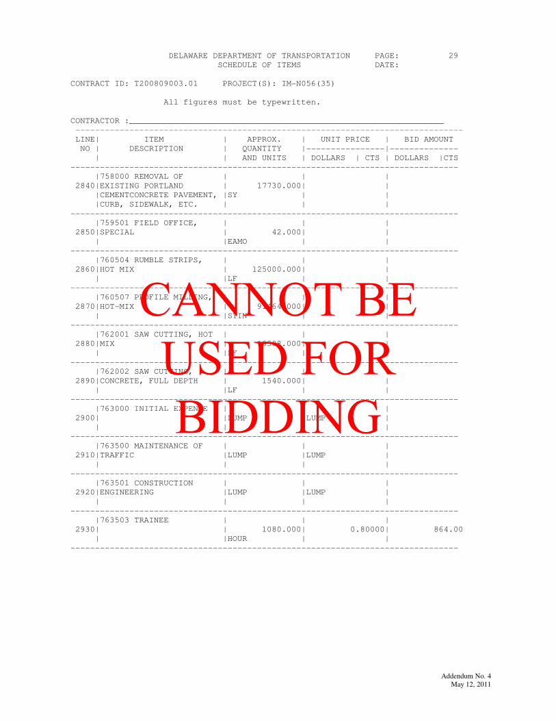
DELAWARE DEPARTMENT OF TRANSPORTATION PAGE: 29
SCHEDULE OF ITEMS DATE:
CONTRACT ID: T200809003.01 PROJECT(S): IM-N056(35)
All figures must be typewritten.
CONTRACTOR :________________________________________________________________
-------------------------------------------------------------------------------
LINE| ITEM | APPROX. | UNIT PRICE | BID AMOUNT
NO | DESCRIPTION | QUANTITY |----------------|--------------
| | AND UNITS | DOLLARS | CTS | DOLLARS |CTS
-------------------------------------------------------------------------------
|758000 REMOVAL OF | | |
2840|EXISTING PORTLAND | 17730.000| |
|CEMENTCONCRETE PAVEMENT, |SY | |
|CURB, SIDEWALK, ETC. | | |
-------------------------------------------------------------------------------
|759501 FIELD OFFICE, | | |
2850|SPECIAL | 42.000| |
| |EAMO | |
-------------------------------------------------------------------------------
|760504 RUMBLE STRIPS, | | |
2860|HOT MIX | 125000.000| |
| |LF | |
-------------------------------------------------------------------------------
|760507 PROFILE MILLING, | | |
2870|HOT-MIX | 91464.000| |
| |SYIN | |
-------------------------------------------------------------------------------
|762001 SAW CUTTING, HOT | | |
2880|MIX | 18308.000| |
| |LF | |
-------------------------------------------------------------------------------
|762002 SAW CUTTING, | | |
2890|CONCRETE, FULL DEPTH | 1540.000| |
| |LF | |
-------------------------------------------------------------------------------
|763000 INITIAL EXPENSE | | |
2900| |LUMP |LUMP |
| | | |
-------------------------------------------------------------------------------
|763500 MAINTENANCE OF | | |
2910|TRAFFIC |LUMP |LUMP |
| | | |
-------------------------------------------------------------------------------
|763501 CONSTRUCTION | | |
2920|ENGINEERING |LUMP |LUMP |
| | | |
-------------------------------------------------------------------------------
|763503 TRAINEE | | |
2930| | 1080.000| 0.80000| 864.00
| |HOUR | |
-------------------------------------------------------------------------------
Addendum No. 4
May 12, 2011
CANNOT BE USED FOR BIDDING

Addendum No. 4
May 12, 2011
CANNOT BE USED FOR BIDDING
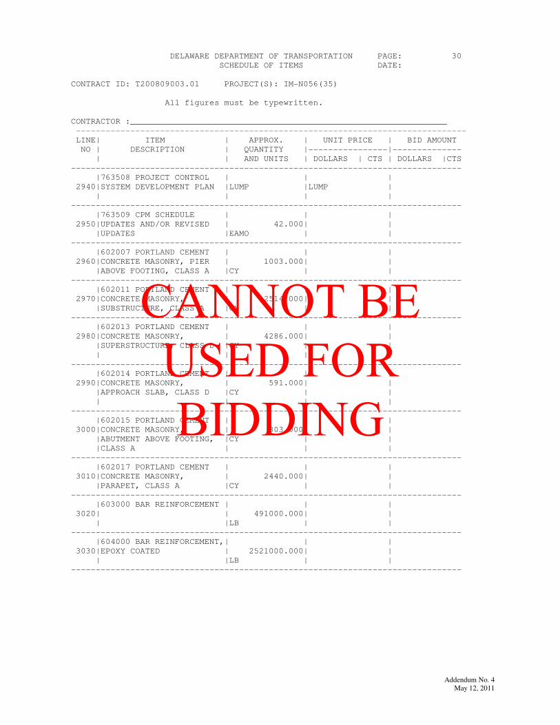
DELAWARE DEPARTMENT OF TRANSPORTATION PAGE: 30
SCHEDULE OF ITEMS DATE:
CONTRACT ID: T200809003.01 PROJECT(S): IM-N056(35)
All figures must be typewritten.
CONTRACTOR :________________________________________________________________
-------------------------------------------------------------------------------
LINE| ITEM | APPROX. | UNIT PRICE | BID AMOUNT
NO | DESCRIPTION | QUANTITY |----------------|--------------
| | AND UNITS | DOLLARS | CTS | DOLLARS |CTS
-------------------------------------------------------------------------------
|763508 PROJECT CONTROL | | |
2940|SYSTEM DEVELOPMENT PLAN |LUMP |LUMP |
| | | |
-------------------------------------------------------------------------------
|763509 CPM SCHEDULE | | |
2950|UPDATES AND/OR REVISED | 42.000| |
|UPDATES |EAMO | |
-------------------------------------------------------------------------------
|602007 PORTLAND CEMENT | | |
2960|CONCRETE MASONRY, PIER | 1003.000| |
|ABOVE FOOTING, CLASS A |CY | |
-------------------------------------------------------------------------------
|602011 PORTLAND CEMENT | | |
2970|CONCRETE MASONRY, | 2514.000| |
|SUBSTRUCTURE, CLASS A |CY | |
-------------------------------------------------------------------------------
|602013 PORTLAND CEMENT | | |
2980|CONCRETE MASONRY, | 4286.000| |
|SUPERSTRUCTURE, CLASS D |CY | |
| | | |
-------------------------------------------------------------------------------
|602014 PORTLAND CEMENT | | |
2990|CONCRETE MASONRY, | 591.000| |
|APPROACH SLAB, CLASS D |CY | |
| | | |
-------------------------------------------------------------------------------
|602015 PORTLAND CEMENT | | |
3000|CONCRETE MASONRY, | 803.000| |
|ABUTMENT ABOVE FOOTING, |CY | |
|CLASS A | | |
-------------------------------------------------------------------------------
|602017 PORTLAND CEMENT | | |
3010|CONCRETE MASONRY, | 2440.000| |
|PARAPET, CLASS A |CY | |
-------------------------------------------------------------------------------
|603000 BAR REINFORCEMENT | | |
3020| | 491000.000| |
| |LB | |
-------------------------------------------------------------------------------
|604000 BAR REINFORCEMENT,| | |
3030|EPOXY COATED | 2521000.000| |
| |LB | |
-------------------------------------------------------------------------------
Addendum No. 4
May 12, 2011
CANNOT BE USED FOR BIDDING

Addendum No. 4
May 12, 2011
CANNOT BE USED FOR BIDDING
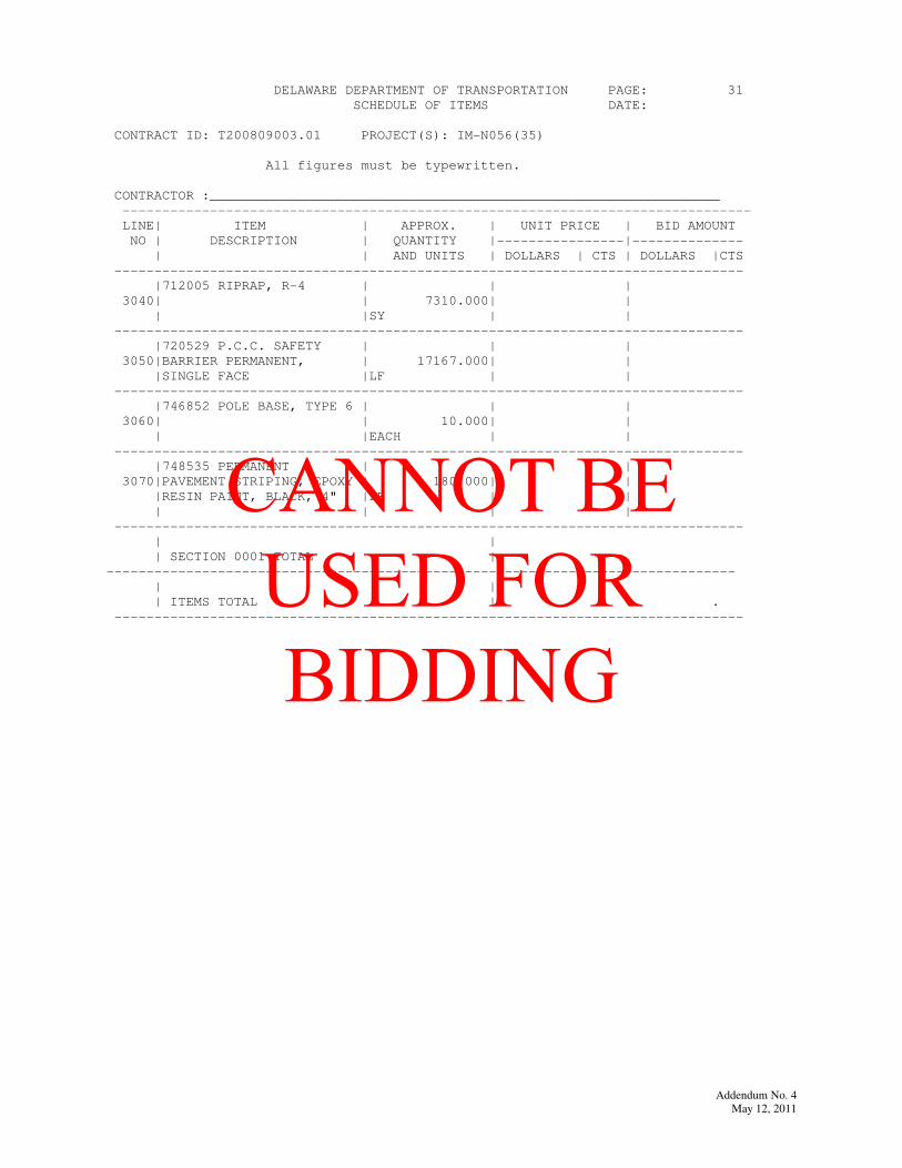
DELAWARE DEPARTMENT OF TRANSPORTATION PAGE: 31
SCHEDULE OF ITEMS DATE:
CONTRACT ID: T200809003.01 PROJECT(S): IM-N056(35)
All figures must be typewritten.
CONTRACTOR :________________________________________________________________
-------------------------------------------------------------------------------
LINE| ITEM | APPROX. | UNIT PRICE | BID AMOUNT
NO | DESCRIPTION | QUANTITY |----------------|--------------
| | AND UNITS | DOLLARS | CTS | DOLLARS |CTS
-------------------------------------------------------------------------------
|712005 RIPRAP, R-4 | | |
3040| | 7310.000| |
| |SY | |
-------------------------------------------------------------------------------
|720529 P.C.C. SAFETY | | |
3050|BARRIER PERMANENT, | 17167.000| |
|SINGLE FACE |LF | |
-------------------------------------------------------------------------------
|746852 POLE BASE, TYPE 6 | | |
3060| | 10.000| |
| |EACH | |
-------------------------------------------------------------------------------
|748535 PERMANENT | | |
3070|PAVEMENT STRIPING, EPOXY | 180.000| |
|RESIN PAINT, BLACK, 4" |LF | |
| | | |
-------------------------------------------------------------------------------
| |
| SECTION 0001 TOTAL |
-------------------------------------------------------------------------------
| |
| ITEMS TOTAL | .
-------------------------------------------------------------------------------
Addendum No. 4
May 12, 2011
CANNOT BE USED FOR BIDDING

Addendum No. 4
May 12, 2011
CANNOT BE USED FOR BIDDING
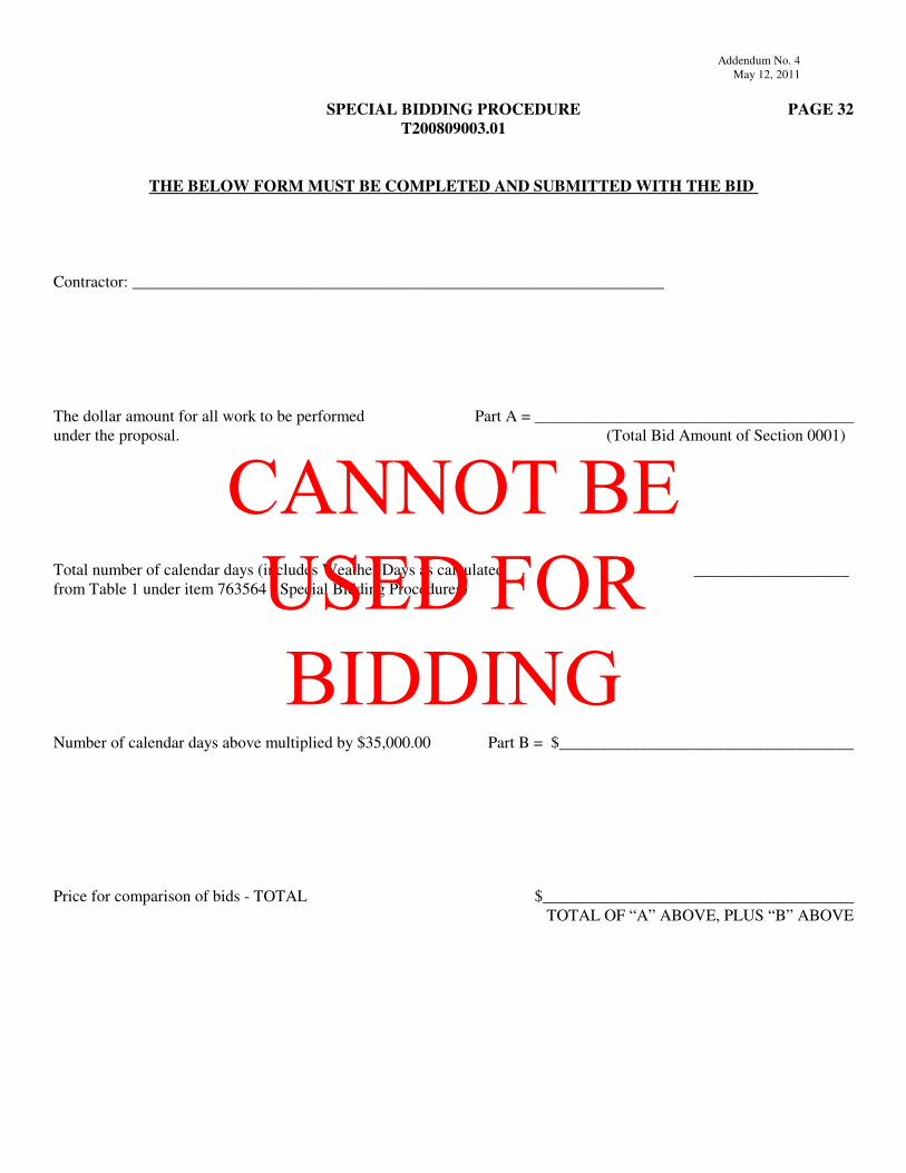
Addendum No. 4
May 12, 2011
SPECIAL BIDDING PROCEDURE PAGE 32
T200809003.01
THE BELOW FORM MUST BE COMPLETED AND SUBMITTED WITH THE BID
Contractor: _________________________________________________________________
The dollar amount for all work to be performed Part A = _______________________________________
under the proposal. (Total Bid Amount of Section 0001)
Total number of calendar days (includes Weather Days as calculated ___________________
from Table 1 under item 763564 - Special Bidding Procedures)
Number of calendar days above multiplied by $35,000.00 Part B = $____________________________________
Price for comparison of bids - TOTAL $______________________________________
TOTAL OF “A” ABOVE, PLUS “B” ABOVE
CANNOT BE USED FOR BIDDING

Addendum No. 4
May 12, 2011Contract No. T200809003.01
SECTION 1 BREAKOUT SHEET - 2A CONTRACT NO. T200809003
ITEM 602772 - MECHANICALLY STABILIZED EARTH WALLS
ITEM
NO.
APPROX.
QTY.UOM DESCRIPTION UNIT PRICE AMOUNT
11 1 LS Wall 12 MSE Wall $ $
12 1 LS Wall 13 MSE Wall $ $
13 1 LS Wall 14 MSE Wall $ $
14 1 LS Wall 15 MSE Wall $ $
15 1 LS Wall 16 MSE Wall $ $
16 1 LS MSE Wall at S1 $ $
17 1 LS MSE Wall at S2 $ $
18 1 LS MSE Wall at S3 $ $
19 1 LS MSE Wall at S4 $ $
20 1 LS MSE Wall at S5 $ $
21 1 LS MSE Wall at S6 $ $
TOTAL ITEM 602772 - MECHANICALLY STABILIZED EARTH WALLS $
(LUMP SUM BID PRICE FOR ITEM 602772)
CANNOT BE USED FOR BIDDING
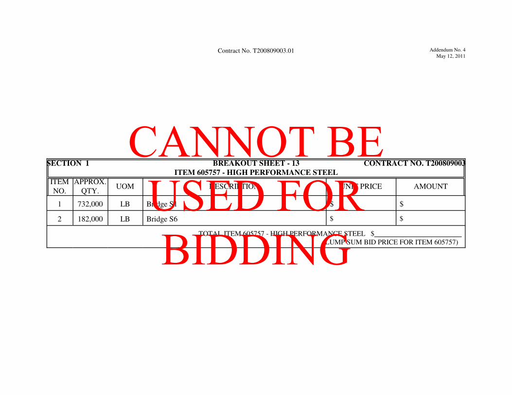
Addendum No. 4
May 12, 2011Contract No. T200809003.01
SECTION 1 BREAKOUT SHEET - 13 CONTRACT NO. T200809003
ITEM 605757 - HIGH PERFORMANCE STEEL
ITEM
NO.
APPROX.
QTY.UOM DESCRIPTION UNIT PRICE AMOUNT
1 732,000 LB Bridge S1 $ $
2 182,000 LB Bridge S6 $ $
TOTAL ITEM 605757 - HIGH PERFORMANCE STEEL $
(LUMP SUM BID PRICE FOR ITEM 605757)
CANNOT BE USED FOR BIDDING

Addendum No. 4
May 12, 2011Contract No. T2008090030.01
FORM SHEETS
THE FOLLOWING SHEETS MUST BE COMPLETED AND RETURNED WITHIN 10 CALENDAR
DAYS BY THE APPARENT LOW BIDDER. FAILURE TO COMPLETE THE FORM SHEETS AS
REQUIRED WILL RESULT IN THE BID BEING DECLARED NON-RESPONSIVE AND THE BID WILL
NOT BE CONSIDERED. FORM SHEETS MUST BE COMPLETED REGARDLESS OF WHETHER
BIDDING BY ELECTRONIC MEANS OR TYPEWRITTEN HARD COPY.
CANNOT BE USED FOR BIDDING

Addendum No. 4
May 12, 2011Contract No. T2008090030.01
CANNOT BE USED FOR BIDDING
Addendum No. 4
May 12, 2011Contract No. T200809003.01
SECTION 1 FORM - 1 for Item720532 CONTRACT NO. T200809003
ITEM 720532 - INSTALL PORTABLE IMPACT ATTENUATOR
ITEM
NO.
APPROX.
QTY.UOM DESCRIPTION UNIT PRICE AMOUNT
$ $
$ $
$ $
$ $
$ $
TOTAL MUST EQUAL BID PRICE FOR ITEM 720532 - INSTALL PORTABLE IMPACT ATTENUATOR $
(BID PRICE FOR ITEM 720532)
Form Page 1
CANNOT BE USED FOR BIDDING

Addendum No. 4
May 12, 2011Contract No. T200809003.01
CANNOT BE USED FOR BIDDING

Addendum No. 4
May 12, 2011Contract No. T200809003.01
SECTION 1 FORM - 2 for Item 720534 CONTRACT NO. T200809003
ITEM 720534 - FURNISH PORTABLE IMPACT ATTENUATOR
ITEM
NO.
APPROX.
QTY.UOM DESCRIPTION UNIT PRICE AMOUNT
$ $
$ $
$ $
$ $
$ $
TOTAL MUST EQUAL BID PRICE FOR ITEM 720534 - FURNISH PORTABLE IMPACT ATTENUATOR $
(BID PRICE FOR ITEM 720534)
Form Page 2
CANNOT BE USED FOR BIDDING

Contract No. T200809003.01
CANNOT BE USED FOR BIDDING

Addendum No. 4May 12, 2011
Contract T200809003.01
Diesel Fuel Cost Price Adjustment Option
The Bidder is required to submit this form within 10 calendar day of the bid opening.
OPTION-IN
9 Checking here selects the option to participate in the 763626 - Diesel Fuel Cost Price Adjustment.
OPTION-OUT
9 Checking here declines the option to participate in the 763626 - Diesel Fuel Cost Price Adjustment.
The undersigned hereby certifies that he/she is authorized to make this Option on behalf of the bidderin compliance with the special provision 763626 - Diesel Fuel Cost Price Adjustment.
Sealed and dated this day of in the year of our Lord two thousand and ( 20 ).
Name of Bidder (Organization)
CorporateSeal
By:Authorized Signature
Attest Title
SWORN TO AND SUBSCRIBED BEFORE ME this day of , 20 .
NotarySeal
Notary
CANNOT BE USED FOR BIDDING