third degree - cal polyusers.csc.calpoly.edu/~zwood/teaching/csc476/finals11/476++write... · third...
TRANSCRIPT
Third DegreeA Senior Project
presented to
the Faculty of the Computer Science department
California Polytechnic State University, San Luis Obispo
In Partial Fulfillment
of the Requirements for the Degree
Bachelor of Science, Computer Science
by
Joshua Marcelo
June, 2011

AbstractAdvancements in computer graphics have paved the way for creating far richer worlds with even greater
detail than ever thought imaginable. Video games take advantage of this continuous technological growth in
order to create worlds that capture the player's attention and immerse them in a visually intriguing playground.
However, video games still follow the same rules of all other games: to provide a provocative activity through a
playful and fun experience. Third Degree seeks to implement advance graphical technologies while creating a
fun and compelling experience for the player.
i
AcknowledgmentsProject Advisor:
Game Programmers:
Differed Rendering Programmer:
Menu/Splash Screen Designer:
Graphic Artists:
Sound/Music Composer:
Writers/Voice-Actors:
Professor Zoë Wood
Tim Biggs
Joshua Marcelo
Jon Moorman
Mark Paddon
Michael Sanchez
Chad Williams
Ryan Schmitt
Hector Zhu
Josh Holland
Ben Funderberg
Tom Funderberg
Mikkel Sandberg
Sam Thorn
Travis Cox
Nora Doane
Mitch Epeneter
Max Sopkin
ii

Table of ContentsAbstract................................................................................................................................................................... i
Acknowledgments.................................................................................................................................................. ii
Introduction............................................................................................................................................................1
Why Video Games?......................................................................................................................................1
Course Structure...........................................................................................................................................1
Project Overview....................................................................................................................................................1
Genre............................................................................................................................................................1
Story.............................................................................................................................................................2
Game Mechanics..........................................................................................................................................2
Look and Feel...............................................................................................................................................2
Project Design..............................................................................................................................................3
Editor..................................................................................................................................................3
Engine................................................................................................................................................3
Game..................................................................................................................................................3
Related Works.........................................................................................................................................................4
Trine.............................................................................................................................................................4
Maya.............................................................................................................................................................4
Doom 3.........................................................................................................................................................5
Algorithms Overview.............................................................................................................................................6
Algorithm Details...................................................................................................................................................7
Editor Object Transformations.....................................................................................................................7
Picking...............................................................................................................................................7
Projection of Axis to Camera Perspective..........................................................................................8

Representing Rotations.......................................................................................................................9
View Frustum Culling.................................................................................................................................11
Player Control.............................................................................................................................................14
Enemy AI....................................................................................................................................................15
Combat.......................................................................................................................................................16
Skeletal Animation.....................................................................................................................................17
MD5 Structure..................................................................................................................................17
Building the Model...........................................................................................................................18
Updating Positions...........................................................................................................................19
Rendering.........................................................................................................................................20
Results..................................................................................................................................................................23
Accomplishments.......................................................................................................................................23
Play-test Feedback......................................................................................................................................24
Development Analysis................................................................................................................................24
Conclusion............................................................................................................................................................25
Future Work..........................................................................................................................................................26
References............................................................................................................................................................27
IntroductionWhy Video Games?
Video games have been driving hardware and graphics development ever since the rise of the first video
game consoles. Having a senior project that consists of making a substantial video game is an excellent way to
learn about and implement many different types of graphics technologies. Building a video game also provides
more experience in all aspects of real world applications development. From the processes of design to team
management, the process of building a game will build experience in the many aspects of software engineering.
For my senior project, I choose to implement a 3D interactive video game related to the platforming action-
adventure genre.
Course StructureThe Third Degree game began in Cal Poly's Winter 2010, CPE 476++ - Real-Time 3-D Computer
Graphics Software Systems class. The focus of the class was to create a video game based within a 3-D
environment, and course requirements called for us to integrate certain graphical technologies into the game. In
CPE 476++, Mark Paddon, Chad Williams and Michael Sanchez had the initial idea for a side-scrolling
platformer built within a 3-D environment called Third Degree. Various people assisted in the project in order to
provide assets and support by way of music, concept art and models, as well as general story development and
voice acting. Tim Biggs, Jon Moorman and I then joined as programmers to also work on the game throughout
CPE 476++, as well as into the Spring 2011 quarter as a senior project where our work on Third Degree
continued with improvements to graphical technologies while also fleshing out the foundation for the story.
Project OverviewGenre
Third Degree is a 3-D side-scrolling action-adventure game. The game takes place in the mind of the
main character where the player is immersed in story driven gameplay. Third Degree combines story elements,
traditional platforming and interesting game mechanics to provide a unique player experience.

StoryThe game follows the story of a convict kept in confinement who is given a chance at redemption
through a special testing program. A recent alien artifact has crash landed on the Earth, and a panel of scientists
are conducting specialized experiments to find out the purpose of this artifact. The convict is one in a line of test
subjects given a chance of freedom through experimentation. When the artifact is fitted on the convict's head, he
is placed in a virtual environment that resembles 1860s England. The convict, though determined to gain his
freedom, soon feels the grasp of insanity closing in around him, and the only way out is to either finish the
virtual simulation, or die trying.
Game MechanicsThe player's health is represented by a Mental Deterioration Bar (MD Bar), representing the player's
sanity level. Over time, the player's mental health slowly deteriorates and the MD Bar increases over time, also
increasing whenever the player takes damage from enemies. As the player traverses a level, they will come
across various enemies that will shoot the player, and the player must kill them by firing back with their own
weapons in order to move on and reach the end of the level. Should the player's MD Bar fill up completely, the
player will die. The player also has access to special abilities that are related to their mental health. These
abilities do not have to be acquired and as of the current release there are two different types of abilities.
The first ability is the “Focus” ability and is used to decrease the player’s MD Bar by holding the ‘f’ key.
In addition to lowering the MD Bar, this ability will also release a shock wave proportional to the amount of MD
that was focused. This ability is very crucial in game play as it is the only ability that will help the player balance
the MD Bar. The second ability is known as “Fire Legs” and is used to help the player reach distances not
normally reachable by a standard jump. This ability when used propels the player towards the direction of the
cursor by an amount proportional to the current MD level.
Look and FeelThird Degree seeks to represent an intense, hectic environment for the player by emphasizing the
characters mental health and overall sanity. The player's sanity level is further represented by the 3-D
environment, where the world slowly transitions between two time eras depending on the player's current mental

health. The first era is set in 18th century, England-esque city scape, while the second is a futuristic, alien world.
These two contrasting periods hopefully convey to the user an overwhelming yet fascinating experience.
Project DesignThe source code was under version control and the primary language was C++. The repository for our
entire project was hosted on Unfuddle.com. All team members were given accounts and access to the repository
to commit and update changes to their projects accordingly.
The design of the project as a whole was broken up into three aspects: engine, editor and game. Third
Degree was built within Microsoft Visual Studio 2008. For our editor's User Interface, we used Nokia’s Qt
libraries and tools. The Visual Studio plug-in was used to integrate Qt and allow us to design the Level Editor.
The game and engine also made use of NVIDIA's PhysX physics engine in order to handle object
movement and collision simulation. Initially, our project used the open source Bullet Physics Engine, but due to
a lack of documentation, integrating it into our project become cumbersome and problematic. After CPE 476++,
our team decided to move away from the Bullet Physics Engine and redesign our game around PhysX due to its
detailed documentation and the wider variety of physics simulation tools.
EditorThe editor provides an interface for the developers to visually create the levels for the Third Degree
game. The editor allows the placement of all game objects, spawn points and lights to create maps to be used
within the physical game.
EngineThe engine handles all graphical applications of Third Degree by handling the rendering of the game by
referencing the objects and particles based upon their transformations and draw methods. The engine also adds
all lights to the environment and sets up the differed rendering to light the world.
GameThe game manages the core game, handling the game state by utilizing the PhysX physics engine in
conjunction with the Third Degree game mechanics. All user interaction and game logic occurs at this layer of
the game in order to set up game state to be drawn by the engine.

Related WorksWhile there were many influences for Third Degree, the following works both influenced the gameplay
as well as helped to provide examples for how to approach certain tasks that were used for the different
components of Third Degree's design.
TrineThe general mood and feel of the game were greatly influenced by this side-scrolling platformer,
Frozenbyte's Trine. Visual inspirations, as well as overall feel of the gameplay mechanics such as movement,
puzzle object interaction and elements of the combat system helped in making decisions for Third Degree. In
Figure 1, a screenshot for Trine is shown depicting some of the art style and overall mood that influenced some
of the design and gameplay of Third Degree.
Fig. 1 – Screenshot for Frozenbyte's Trine
MayaSome of the editor's functionality, particularly the transformation tools, were modeled after many 3-D
graphics software, particularly Autodesk Maya. Figure 2 shows an example of the transformation tools used in
Maya.
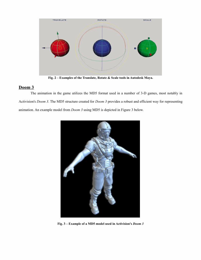
Fig. 2 – Examples of the Translate, Rotate & Scale tools in Autodesk Maya.
Doom 3The animation in the game utilizes the MD5 format used in a number of 3-D games, most notably in
Activision's Doom 3. The MD5 structure created for Doom 3 provides a robust and efficient way for representing
animation. An example model from Doom 3 using MD5 is depicted in Figure 3 below.
Fig. 3 – Example of a MD5 model used in Activision's Doom 3
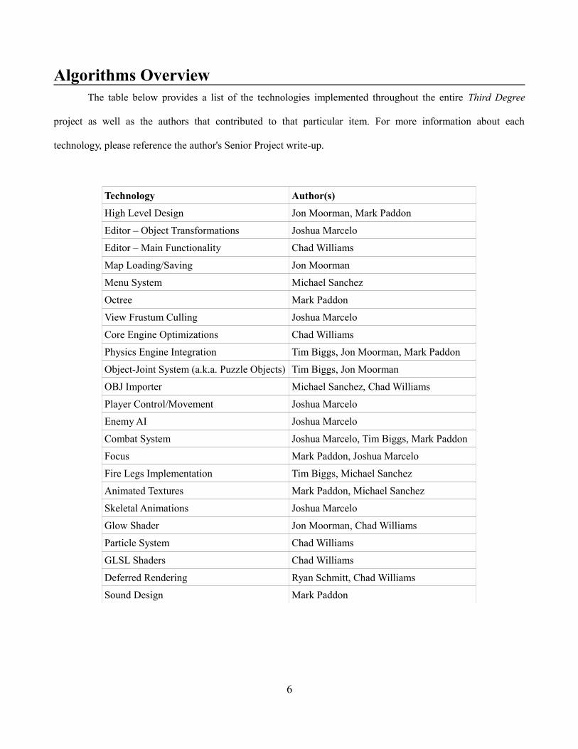
Algorithms OverviewThe table below provides a list of the technologies implemented throughout the entire Third Degree
project as well as the authors that contributed to that particular item. For more information about each
technology, please reference the author's Senior Project write-up.
Technology Author(s)High Level Design Jon Moorman, Mark Paddon
Editor – Object Transformations Joshua Marcelo
Editor – Main Functionality Chad Williams
Map Loading/Saving Jon Moorman
Menu System Michael Sanchez
Octree Mark Paddon
View Frustum Culling Joshua Marcelo
Core Engine Optimizations Chad Williams
Physics Engine Integration Tim Biggs, Jon Moorman, Mark Paddon
Object-Joint System (a.k.a. Puzzle Objects) Tim Biggs, Jon Moorman
OBJ Importer Michael Sanchez, Chad Williams
Player Control/Movement Joshua Marcelo
Enemy AI Joshua Marcelo
Combat System Joshua Marcelo, Tim Biggs, Mark Paddon
Focus Mark Paddon, Joshua Marcelo
Fire Legs Implementation Tim Biggs, Michael Sanchez
Animated Textures Mark Paddon, Michael Sanchez
Skeletal Animations Joshua Marcelo
Glow Shader Jon Moorman, Chad Williams
Particle System Chad Williams
GLSL Shaders Chad Williams
Deferred Rendering Ryan Schmitt, Chad Williams
Sound Design Mark Paddon
6
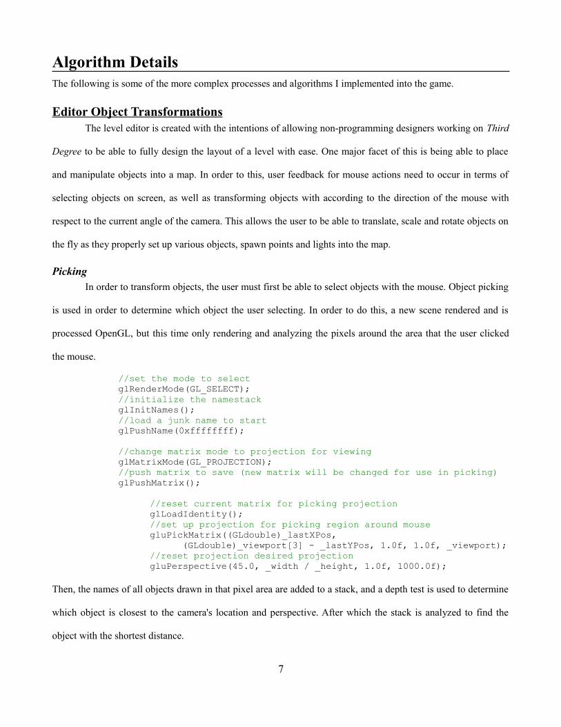
Algorithm DetailsThe following is some of the more complex processes and algorithms I implemented into the game.
Editor Object TransformationsThe level editor is created with the intentions of allowing non-programming designers working on Third
Degree to be able to fully design the layout of a level with ease. One major facet of this is being able to place
and manipulate objects into a map. In order to this, user feedback for mouse actions need to occur in terms of
selecting objects on screen, as well as transforming objects with according to the direction of the mouse with
respect to the current angle of the camera. This allows the user to be able to translate, scale and rotate objects on
the fly as they properly set up various objects, spawn points and lights into the map.
PickingIn order to transform objects, the user must first be able to select objects with the mouse. Object picking
is used in order to determine which object the user selecting. In order to do this, a new scene rendered and is
processed OpenGL, but this time only rendering and analyzing the pixels around the area that the user clicked
the mouse.
//set the mode to selectglRenderMode(GL_SELECT);//initialize the namestackglInitNames();//load a junk name to startglPushName(0xffffffff);
//change matrix mode to projection for viewingglMatrixMode(GL_PROJECTION);//push matrix to save (new matrix will be changed for use in picking)glPushMatrix();
//reset current matrix for picking projectionglLoadIdentity();//set up projection for picking region around mousegluPickMatrix((GLdouble)_lastXPos,
(GLdouble)_viewport[3] - _lastYPos, 1.0f, 1.0f, _viewport);//reset projection desired projectiongluPerspective(45.0, _width / _height, 1.0f, 1000.0f);
Then, the names of all objects drawn in that pixel area are added to a stack, and a depth test is used to determine
which object is closest to the camera's location and perspective. After which the stack is analyzed to find the
object with the shortest distance.
7

//set ptr to start of bufferptr = (GLuint *) buffer;//set min to first object's depth - minZminZ = *(ptr + 1);//traverse hits and print the names of the objects hitfor (int i = 0; i < hits; i++){
//start the list of object's names at ptr position to “names”names = *ptr;//check if zmin of current stack item is lowestif((*(ptr + 1)) <= minZ){
//save data for lowest z-depth:// number of names, minimum depth, and names ptr
numNames = names;minZ = *(ptr + 1);minNames = ptr + 3;
}//advance the pointer to list of names - 4th element in arrayptr = ptr+3;//go past the list of names at this depthptr += names;
}
Now that the object has been selected, transformations can be done.
Projection of Axis to Camera PerspectiveAll transformations of an object are done with respect to the x-axis, y-axis or z-axis. Additionally, the
camera in the editor is free roaming so that the user can view the map at any angle when building a level.
However, mouse movement across a screen for various transformations occur according to the current camera
view, and since the camera perspective of the map can be positioned or angled in any number of ways, the
perspective of objects and the different directional axes can be in number of positions and angles themselves.
This can greatly affect the directions a user wishes to manipulate the objects with their mouse. Figure 6 gives an
example of how an axis can be manipulated at different angles in relation to the camera.
Fig. 4 – Example of the translate tool showing how an axiswill need to be transformed at different camera angles.
8

Therefore, since transformations along a specific axis needs to reflect the direction of movement of the
mouse according to a certain camera perspective, the axis the transformation is occurring must first be projected
onto the plane of the screen.
//direction camera is pointingNxVec3 cam_vect(_camera.x - _lookAt.x, _camera.y - _lookAt.y,
_camera.z - _lookAt.z);//normal of the plane the camera lies on (ie, the screen)NxVec3 cam_norm(_lookAt.x - _camera.x, _lookAt.y - _camera.y,
_lookAt.z - _camera.z);
//get the projection of the axis to the camera's planeNxVec3 axis_proj = axis - (cam_norm * (cam_norm.dot(axis)));//normalizeaxis_proj.normalize();
Now the direction and movement of the mouse can be properly related to the axis of transformation by
projecting the mouse's movement vector to the new axis projection in order to handle all transformations with
respect to the user's perspective.
Representing RotationsRepresentation for the translation and scaling of an object can be represented by projecting the mouse's
movement onto the axis of the respective transformations. However, extra work needs to be done in order to
represent rotations. While quaternions are used in order to provide accurate and flexible representation for
rotations, Euler angle equivalents need to be represented in the editor so the user has a neat representation for the
rotation of an object. The following function transforms the quaternion (represented by datatype NxQuat) into a
vector (represented by NxVec3) containing the Euler angles.
NxVec3 GetEulerAngles(NxQuat quat){
float yaw(0.0f); //zfloat pitch(0.0f); //yfloat roll(0.0f); //x
//transformation matrix data structureNxMat33 mat(quat);//vectors to hold major rowsNxVec3 row[3];
//save rows from matrix into arrayfor(int i = 0; i < 3; i++){
mat.getRow(i, row[i]);}
9

//check for gimble lock between z and y axisif(fabsf(row[2].x) >= 1.0f){
//x rotational shiftfloat delta = atan2f(row[0].x, row[0].z);//set z rotation to zeroyaw = 0.0f;//check direction of rotationif(row[2].x > 0.0f){
//y = 90pitch = M_PI / 2.0f;//x rotationroll = pitch + delta;
}else{
//y = -90pitch = -M_PI / 2.0f;//x rotationroll = -pitch + delta;
}}else{
//standard rotation pulled from transformation matrixpitch = -asinf(row[2].x);roll = atan2f(row[2].y / cosf(pitch), row[2].z /
cosf(pitch));yaw = atan2f(row[1].x / cosf(pitch), row[0].x /
cosf(pitch));}//convert to degreesyaw *= 180.0f / M_PI; //zpitch *= 180.0f / M_PI; //yroll *= 180.0f / M_PI; //xreturn NxVec3(roll, pitch, yaw);
}
In order for OpenGL to utilize a quaternion value, the quaternion needs to be represented as the angle of rotation
about the Euler rotation axis.
angle(Θ) = 2.0∗cos−1(w)
axis(x,y,z) = (1.0, 0.0, 0.0) if angle(Θ) = 0,= ( x
1−w 2 , y1−w 2 , z
1−w2 ) otherwise
The angle and axis obtained are then used to generate the rotation transformation for a given object. Through
this, the user can freely rotate objects in a variety of angles when using the level editor.
10

View Frustum CullingFor a large number of games, especially 3-D games like Third Degree, many objects can exist in the
environment at any particular moment, both on-screen and off-screen. All of those objects are represented by
hundreds, often times thousands of meshes, each of which are comprised of several vertices. That means that
more often than not, a full game may contain millions of vertices throughout each instance of its environment.
In order to improve the speed and efficiency of the graphics pipeline, objects not in view of the camera's
perspective will be removed manually by the program before sending all the object data to the GPU. This
process is called View Frustum Culling. Parts of the culling process is much faster when done manually through
the program because several optimizations can occur on the programming side when analyzing objects, which
will be specified later. Additionally, since a large number of vertices are no longer sent down the graphics
pipeline, View Frustum Culling allows for improved speed and efficiency to the graphics system.
The first step of View Frustum Culling is to set up a representation of the camera's view frustum. When
a camera's perspective is set up, the environment it perceives is enclosed in a view frustum. The view frustum is
a volume that encloses a section of the environment into the view frustum's top, bottom, left, right, near and far
planes, representing area of the environment currently visible to the camera. Figure 5 provides a visual
representation of the view frustum volume.
Fig. 5 – View frustum based on the camera's position and perspective
OpenGL uses the command gluLookAt as a way to set the camera's position, as well as setting the near
and far limits of the frustum. The program then creates the view frustum's volume based upon those settings. In
order to determine the dimensions of the view frustum, we use the environment's transformation matrix in order
11

to derive the planes of the view frustum. The following takes a 4x4 matrix and converts that information into the
six planes of the view frustum.
//left plane_camPlanes[0] = NxPlane(tMatrix[0][3] + tMatrix[0][0],
tMatrix[1][3] + tMatrix[1][0],tMatrix[2][3] + tMatrix[2][0],tMatrix[3][3] + tMatrix[3][0]);
//right plane_camPlanes[1] = NxPlane(tMatrix[0][3] - tMatrix[0][0],
tMatrix[1][3] - tMatrix[1][0],tMatrix[2][3] - tMatrix[2][0],tMatrix[3][3] - tMatrix[3][0]);
//bottom plane_camPlanes[2] = NxPlane(tMatrix[0][3] + tMatrix[0][1],
tMatrix[1][3] + tMatrix[1][1],tMatrix[2][3] + tMatrix[2][1],tMatrix[3][3] + tMatrix[3][1]);
//top plane_camPlanes[3] = NxPlane(tMatrix[0][3] - tMatrix[0][1],
tMatrix[1][3] - tMatrix[1][1],tMatrix[2][3] - tMatrix[2][1],tMatrix[3][3] - tMatrix[3][1]);
//far plane_camPlanes[4] = NxPlane(tMatrix[0][3] + tMatrix[0][2],
tMatrix[1][3] + tMatrix[1][2],tMatrix[2][3] + tMatrix[2][2],tMatrix[3][3] + tMatrix[3][2]);
//near plane_camPlanes[5] = NxPlane(tMatrix[0][3] - tMatrix[0][2],
tMatrix[1][3] - tMatrix[1][2],tMatrix[2][3] - tMatrix[2][2],tMatrix[3][3] – tMatrix[3][2]);
After defining the view frustum, we can apply different optimization techniques to the culling process. One way
is that instead of individually analyzing each vertex of an object, we can generalize the entire object as a
bounding box shape that encompasses all the vertices of an object. This way, we can quickly determine if no part
of an object lies within the view frustum, removing the need of analyzing the object's vertices completely. When
iterating through all the objects in the scene, the program analyzes each of them and checks if that object's
bounding box is within the view frustum. The following code checks if a particular bounding box lies within the
camera's view frustum.
bool CameraFrustum::ContainsBox(NxBounds3 bounds){
//setup the corners of the bounding boxNxVec3 corners[8] ={
NxVec3(bounds.min.x, bounds.min.y, bounds.min.z),
12
NxVec3(bounds.min.x, bounds.min.y, bounds.max.z),NxVec3(bounds.min.x, bounds.max.y, bounds.min.z),NxVec3(bounds.min.x, bounds.max.y, bounds.max.z),NxVec3(bounds.max.x, bounds.min.y, bounds.min.z),NxVec3(bounds.max.x, bounds.min.y, bounds.max.z),NxVec3(bounds.max.x, bounds.max.y, bounds.min.z),NxVec3(bounds.max.x, bounds.max.y, bounds.max.z)
};
//check each plane to see if corners are on wrong side of planefor(int plane_index = 0; plane_index < 6; plane_index++){
//plane contains box if at least one corner is in viewbool contains = false;for(int corner_index = 0; corner_index < 8; corner_index++){
contains =contains || (_camPlanes[plane_index].distance(
corners[corner_index]) >= -0.0001f);}
//if box is not in view of plane return falseif(!contains){
return false;}
}
//return true if the box was on the correct side of all planesreturn true;
}
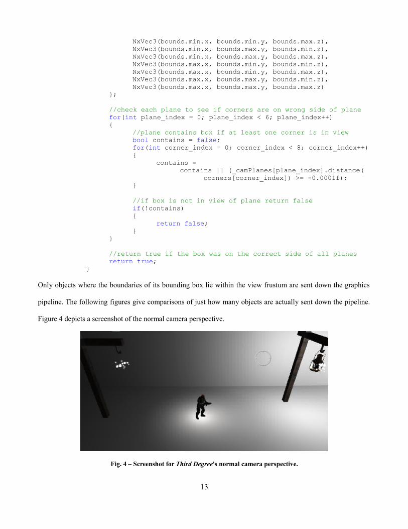
Only objects where the boundaries of its bounding box lie within the view frustum are sent down the graphics
pipeline. The following figures give comparisons of just how many objects are actually sent down the pipeline.
Figure 4 depicts a screenshot of the normal camera perspective.
Fig. 4 – Screenshot for Third Degree's normal camera perspective.
13

In Figure 5, a comparison is given for a zoomed out view of the camera's perspective in Figure 4. The entire map
is shown, portraying just how much of the map is culled out when View Frustum Culling is applied.
Fig. 5 – Comparison of the entire level for when the objects outside of the view frustum are culled (left)and when the objects are not culled (right).
Player ControlSide-scrolling platformers require smooth and intuitive movement that properly reflect the user input.
The player in the game is capable of running left and right, either forwards or backwards depending on the
placement of the mouse with respect to the player. The player faces left or right by comparing the position of the
mouse with where the player resides at the center of the screen. This allows the player to shoot more freely in all
directions in an intuitive manner. Additionally, the player is capable of jumping, crouching, and crouch walking
in either direction as well. Furthermore, pacing of the player became an important issue as the character needed
particular movement speeds for not only when running, but also as the player moved in the crouching position,
as well as the height and distance of a player's jump. Figure 6 gives an example of some of the different
movement actions the player can perform.
Fig. 6 – Depictions of character movement from left to right: Running, crouch walking, and jumping
14

Another problem that came up with was dealing with player collision with the environment. Although
the players movement in the game is controlled primarily by the user, player objects must have unique responses
to the environment, such as reacting to moving objects, or getting hurt by hazardous areas. Callbacks and object
states needed to be consistently updated and tracked throughout the game. All these properties needed to be
tweaked through numerous play-tests in order to get a fluid control system.
Enemy AIThird Degree utilizes enemy combat to increase the action oriented aspect of the game. The key
functionality of the enemies is to patrol areas of the level, as well as to attack the player whenever they across
them, and all is maintained and controlled by an internal artificial intelligence (AI) system. Initially, our team
had planned on having a separate AI programming team develop the controls for enemy units.
Although that team had started on initial designs for an AI system, communication, scheduling and
overall work output became a serious issue. Eventually, the core Third Degree team decided to scrap the
previous AI team's work, and I solely took over design and implementation of the AI. Due to some time
constraints after having to retool AI design, a very basic artificial intelligence was created by me for enemies that
would have the enemy units transition between different combat states when interacting with the game
environment.
The enemy starts off patrolling a specified area of the level within a fixed range. Enemies would
continuously “patrol” this area, represented by the enemy unit pacing back and forth, and the enemy continues
this until the player crosses into that enemy's “alert” range. When an enemy has become alerted to the player's
proximity, the enemy briefly signifies their alerted state to the player by jumping. This action helps provide a
feedback to the player that they have been spotted.
After this, the enemy switches to an attack state where they periodically shoot the player until either the
player runs away out of range, the player kills the enemy, or the enemy kills the player. If the player runs away
or manages to get around passed the enemy, the enemy will go back into patrol mode, where the enemy will
restart its cycle until coming across the player once again. Should the player manage to kill the enemy, the
enemy unit is removed from the level by turning off all collision instances for the enemy, as well as no longer
15
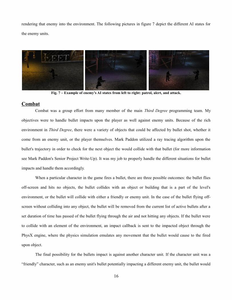
rendering that enemy into the environment. The following pictures in figure 7 depict the different AI states for
the enemy units.
Fig. 7 – Example of enemy's AI states from left to right: patrol, alert, and attack.
CombatCombat was a group effort from many member of the main Third Degree programming team. My
objectives were to handle bullet impacts upon the player as well against enemy units. Because of the rich
environment in Third Degree, there were a variety of objects that could be affected by bullet shot, whether it
come from an enemy unit, or the player themselves. Mark Paddon utilized a ray tracing algorithm upon the
bullet's trajectory in order to check for the next object the would collide with that bullet (for more information
see Mark Paddon's Senior Project Write-Up). It was my job to properly handle the different situations for bullet
impacts and handle them accordingly.
When a particular character in the game fires a bullet, there are three possible outcomes: the bullet flies
off-screen and hits no objects, the bullet collides with an object or building that is a part of the level's
environment, or the bullet will collide with either a friendly or enemy unit. In the case of the bullet flying off-
screen without colliding into any object, the bullet will be removed from the current list of active bullets after a
set duration of time has passed of the bullet flying through the air and not hitting any objects. If the bullet were
to collide with an element of the environment, an impact callback is sent to the impacted object through the
PhysX engine, where the physics simulation emulates any movement that the bullet would cause to the fired
upon object.
The final possibility for the bullets impact is against another character unit. If the character unit was a
“friendly” character, such as an enemy unit's bullet potentially impacting a different enemy unit, the bullet would
16

pass through that object, since friendly fire is removed from the game. The ray tracer would then update the
bullet with a new object that it would potentially hit. If the fired upon character was a “non-friendly” character to
the bullet's owner, such as the player shooting an enemy unit, then a callback would occur that would damage
the hit character's health. Tweaks to gameplay occurred through game testing in order to determine appropriate
damage levels for the weapons. Balance was needed that would create enough of a challenge to the player with
combat against enemies while maintaining a free flowing platforming experience. Figure 8 gives an example of
the combat between a player and the enemy.
Fig. 8 – Example of a gunfight between the player (left) and the enemy (right).
Skeletal AnimationAnimated modeling can be a very complex process. Constantly maintaining positional data for every vertex can
be a computational and memory intensive process. Skeletal animation helps this process by simplifying the
structure of models to a skeleton, and basin movement for the model around its skeletal structure. All 3-D
animation within Third Degree utilizes skeletal animation, where the vertices for animated objects are anchored
to a hierarchical joint structure.
MD5 StructureThe data for the skeletal animation is stored in md5mesh and md5anim files. The program parses all files
needed for the game and saves the data to generate the animated models. The core structure of the model is
found within the md5mesh file. Each model contains a group of textures, joints and meshes. All joints are given
a starting base position and base rotation, where the rotation of the joint is based upon the local space around that
joint's parent joint position.
Each mesh within the model is a triangular mesh consisting of three vertices. Each vertex in the model
has a texture coordinate and a list of weights associated to it. For those list of weights, each weight references a
17
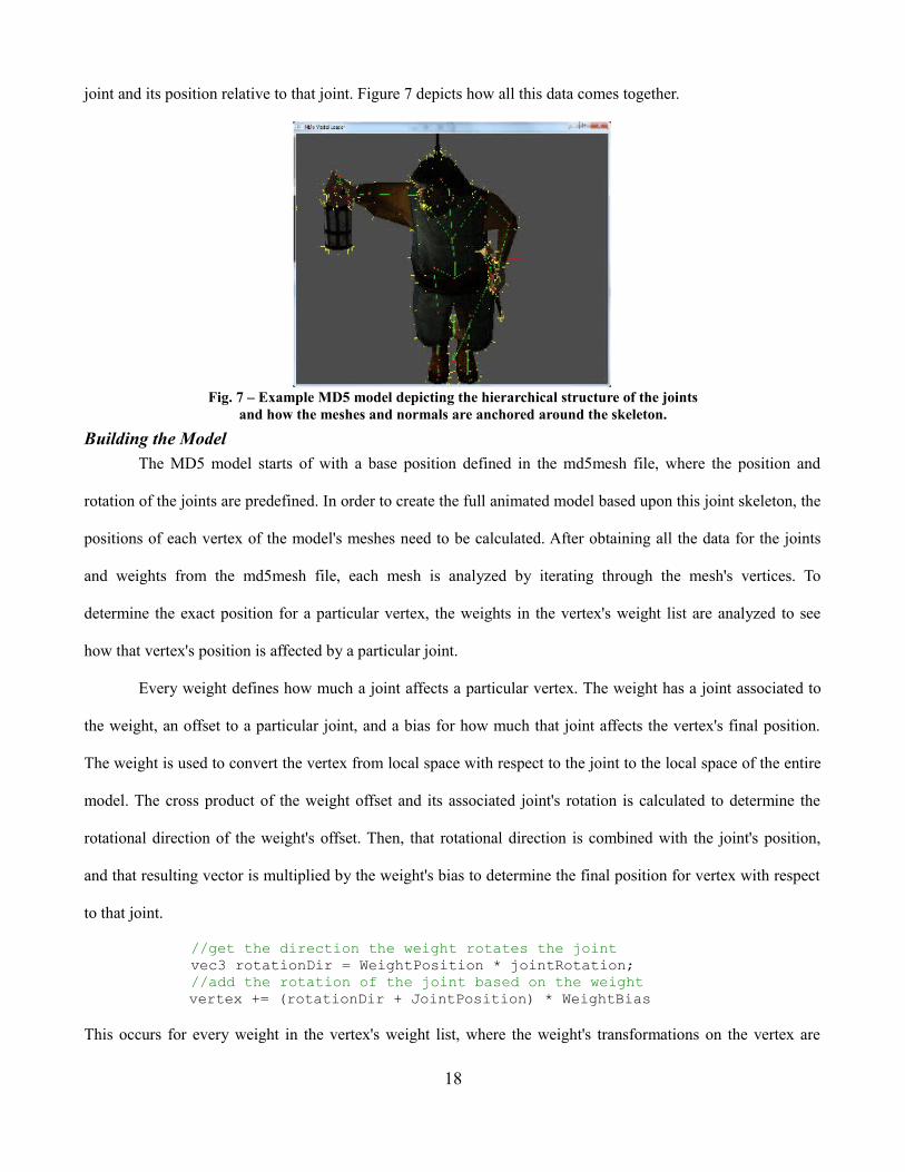
joint and its position relative to that joint. Figure 7 depicts how all this data comes together.
Fig. 7 – Example MD5 model depicting the hierarchical structure of the jointsand how the meshes and normals are anchored around the skeleton.
Building the ModelThe MD5 model starts of with a base position defined in the md5mesh file, where the position and
rotation of the joints are predefined. In order to create the full animated model based upon this joint skeleton, the
positions of each vertex of the model's meshes need to be calculated. After obtaining all the data for the joints
and weights from the md5mesh file, each mesh is analyzed by iterating through the mesh's vertices. To
determine the exact position for a particular vertex, the weights in the vertex's weight list are analyzed to see
how that vertex's position is affected by a particular joint.
Every weight defines how much a joint affects a particular vertex. The weight has a joint associated to
the weight, an offset to a particular joint, and a bias for how much that joint affects the vertex's final position.
The weight is used to convert the vertex from local space with respect to the joint to the local space of the entire
model. The cross product of the weight offset and its associated joint's rotation is calculated to determine the
rotational direction of the weight's offset. Then, that rotational direction is combined with the joint's position,
and that resulting vector is multiplied by the weight's bias to determine the final position for vertex with respect
to that joint.
//get the direction the weight rotates the jointvec3 rotationDir = WeightPosition * jointRotation;//add the rotation of the joint based on the weightvertex += (rotationDir + JointPosition) * WeightBias
This occurs for every weight in the vertex's weight list, where the weight's transformations on the vertex are
18

added together to determine the final position. Once every vertex position is determined, the meshes for the
animated model can be rendered in the appropriate position and the complete model can be drawn.
Updating PositionsEach animation cycle is saved within an md5anim file and is loaded at start-up. The animation file
contains a variety of information about the animation cycle, but most importantly it specifies how many frames
are in the cycle, the frame rate for an animation, a list of key frames, and the position of the model at each of
those frames. At startup, the skeletal pose of the model for each frame is saved so that the program can refrenece
this data in order to position the model through the animation cycle.
When the model is being updated during the animation cycle, the program must figure out at what stage
the model is at in the animation cycle. Very rarely does an animation lie directly on a particular key frame.
Because of this, the program needs to determines which two key frames the model is between in the current
animation cycle.
//increment time-step_animTime += timeElapsed;
//make sure animation ime is between the overall animation durationwhile(_animTime > _animDuration){
_animTime -= _animDuration;}while(_animTime < 0.0f){
_animTime += _animDuration;}
//calculate current and next framefloat frameNum = _animTime * (float)_frameRate;int frame0 = (int)floorf(frameNum);int frame1 = (int)ceilf(frameNum);frame0 = frame0 % _numFrames;frame1 = frame1 % _numFrames;
Also, because frames only provide the key positions of the model, interpolation must be done in order to
fill in the gaps and generate the motion and position between the two frames.
//determine how much time between current frame and next frame_fInterpolate = fmodf(_animTime, _frameDuration) / _frameDuration;//interpolate in between the two frame positions based upon timeInterpolateSkeletons(_skeletonList[frame0], _skeletonList[frame1],
_fInterpolate);
19

The joints of the model's skeleton is then interpolated between the frames to determine the final
positional data for interpolated joint.
//update jointfinalJoint.ParentID = joint0.ParentID;
//interpolate between positions linearlyfinalJoint.Position = (joint0.Position * (1.0f - fInterpolate)) +
(joint1.Position * fInterpolate);
//get angle between quaternions to use for slerpfloat s_angle = acosf(quat0.dot(quat1));//do spherical linear interpolation to get rotation datafinalJoint.Quat =
quat1 * sinf((1 – fInterpolate) * s_angle) / sinf(s_angle) -quat2 * sinf(fInterpolate * s_angle) / sinf(s_angle);
Joint data is now set for the skeletal at the current animations pose, and the models position is rebuilt
based upon the new skeletal joint positions and rotations.
RenderingBecause the vertices of the animated model are weighted to the joints of the skeleton, every vertex must
be updated constantly. However, this can be a very computational intensive process since the vertices must be
constantly updated and then sent to the GPU to be transformed yet again when positioning them to world space.
In order to relieve some of the load onto the GPU, a vertex shader is used to boost processing power by having
all vertex transformation calculations occur on the GPU. That way, vertex position with respect to the joints is
also calculated along with the overall transformation matrix in one process.
However, the models data must first be sent to the GPU to perform the calculations. When using GLSL,
the program needs to get the location of the variables used in the shader and enable a link between the program
and the GPU. In this situation, those variables are the joints and weights.
//locations of attributes in vertex shaderGLint weightLocs[MAX_JOINT_WEIGHTS];GLint jointIDsLoc0, jointIDsLoc1;
//locations of uniformsGLint jointPosLoc, jointQuatLoc;
//get the location of the attributes for the weight and quat datafor(int index = 0; index < MAX_JOINT_WEIGHTS; index++){
std::stringstream weightStr;
20
weightStr << "Weight" << index << "";weightLocs[index] =
glGetAttribLocation(_animationShader->Program,weightStr.str().c_str());
}
jointIDsLoc0 =glGetAttribLocation(_animationShader->Program, "JointIDs0");
jointIDsLoc1 =glGetAttribLocation(_animationShader->Program, "JointIDs1");
jointPosLoc =glGetUniformLocation(_animationShader->Program, "JointPos");
jointQuatLoc =glGetUniformLocation(_animationShader->Program, "JointQuat");
//enable vertex arraysglEnableClientState(GL_VERTEX_ARRAY);glEnableClientState(GL_TEXTURE_COORD_ARRAY);glEnableClientState(GL_NORMAL_ARRAY);
//enable attribute arraysfor(int index = 0; index < MAX_JOINT_WEIGHTS; index++){
glEnableVertexAttribArray(weightLocs[index]);}glEnableVertexAttribArray(jointIDsLoc0);glEnableVertexAttribArray(jointIDsLoc1);
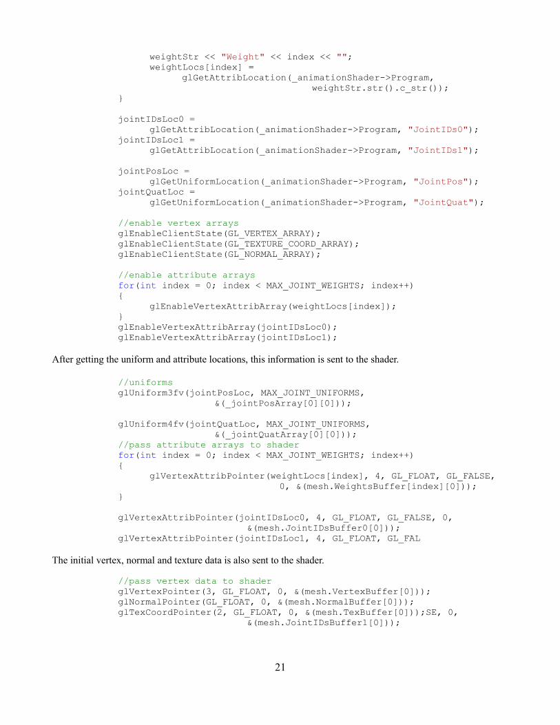
After getting the uniform and attribute locations, this information is sent to the shader.
//uniformsglUniform3fv(jointPosLoc, MAX_JOINT_UNIFORMS,
&(_jointPosArray[0][0]));
glUniform4fv(jointQuatLoc, MAX_JOINT_UNIFORMS,&(_jointQuatArray[0][0]));
//pass attribute arrays to shaderfor(int index = 0; index < MAX_JOINT_WEIGHTS; index++){
glVertexAttribPointer(weightLocs[index], 4, GL_FLOAT, GL_FALSE,0, &(mesh.WeightsBuffer[index][0]));
}
glVertexAttribPointer(jointIDsLoc0, 4, GL_FLOAT, GL_FALSE, 0,&(mesh.JointIDsBuffer0[0]));
glVertexAttribPointer(jointIDsLoc1, 4, GL_FLOAT, GL_FAL
The initial vertex, normal and texture data is also sent to the shader.
//pass vertex data to shaderglVertexPointer(3, GL_FLOAT, 0, &(mesh.VertexBuffer[0]));glNormalPointer(GL_FLOAT, 0, &(mesh.NormalBuffer[0]));glTexCoordPointer(2, GL_FLOAT, 0, &(mesh.TexBuffer[0]));SE, 0,
&(mesh.JointIDsBuffer1[0]));
21
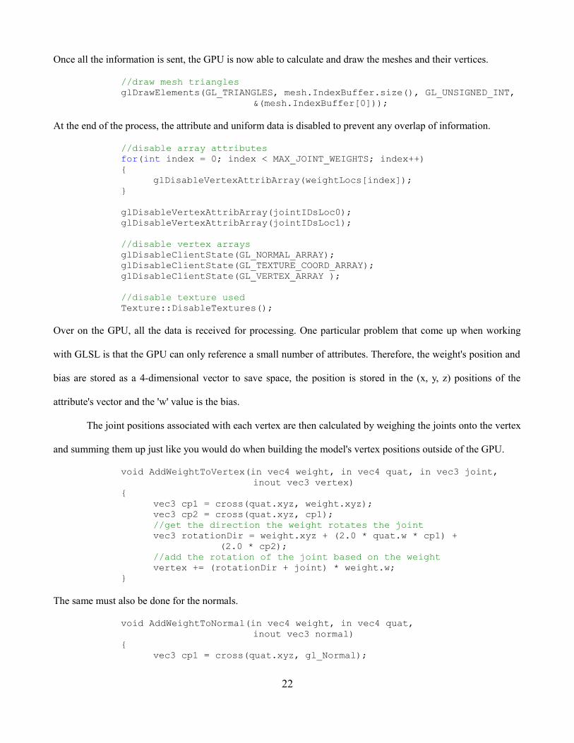
Once all the information is sent, the GPU is now able to calculate and draw the meshes and their vertices.
//draw mesh trianglesglDrawElements(GL_TRIANGLES, mesh.IndexBuffer.size(), GL_UNSIGNED_INT,
&(mesh.IndexBuffer[0]));
At the end of the process, the attribute and uniform data is disabled to prevent any overlap of information.
//disable array attributesfor(int index = 0; index < MAX_JOINT_WEIGHTS; index++){
glDisableVertexAttribArray(weightLocs[index]);}
glDisableVertexAttribArray(jointIDsLoc0);glDisableVertexAttribArray(jointIDsLoc1);
//disable vertex arraysglDisableClientState(GL_NORMAL_ARRAY);glDisableClientState(GL_TEXTURE_COORD_ARRAY);glDisableClientState(GL_VERTEX_ARRAY );
//disable texture usedTexture::DisableTextures();
Over on the GPU, all the data is received for processing. One particular problem that come up when working
with GLSL is that the GPU can only reference a small number of attributes. Therefore, the weight's position and
bias are stored as a 4-dimensional vector to save space, the position is stored in the (x, y, z) positions of the
attribute's vector and the 'w' value is the bias.
The joint positions associated with each vertex are then calculated by weighing the joints onto the vertex
and summing them up just like you would do when building the model's vertex positions outside of the GPU.
void AddWeightToVertex(in vec4 weight, in vec4 quat, in vec3 joint, inout vec3 vertex)
{vec3 cp1 = cross(quat.xyz, weight.xyz);vec3 cp2 = cross(quat.xyz, cp1);//get the direction the weight rotates the jointvec3 rotationDir = weight.xyz + (2.0 * quat.w * cp1) +
(2.0 * cp2);//add the rotation of the joint based on the weightvertex += (rotationDir + joint) * weight.w;
}
The same must also be done for the normals.
void AddWeightToNormal(in vec4 weight, in vec4 quat,inout vec3 normal)
{vec3 cp1 = cross(quat.xyz, gl_Normal);
22

vec3 cp2 = cross(quat.xyz, cp1);vec3 rotatedNormal = gl_Normal + (2.0 * quat.w * cp1) +
(2.0 * cp2);//add the rotation of the joint to the normalnormal += rotatedNormal * weight.w;
}
After the vertex position in the model's local space is calculated, the vertex is then takes the transformation
matrix and converts it to global space.
gl_Position = gl_ModelViewProjectionMatrix * vec4(newPos, 1.0);
A fragment shader is also used to save lighting data to be used by differed shader.
vec3 packedNormal = (normalize(normal) + 1.0)*0.5; //compress normalgl_FragData[0] = vec4(packedNormal, 1.0);gl_FragData[1] = texture2D(tex, Texcoord);gl_FragData[2] = vec4(0.0, 0.0, 0.0, 1.0);
ResultsAccomplishments
Third Degree's development started with the intentions of creating a unique player experience that
integrates the story into the gameplay in a fluid manner. As a whole, development and focus shifted more
towards the graphical technologies of the game. The visual representation and integration for the Mental
Deterioration Bar with the environment were very positive. As a whole, the graphics are the main feature for the
current version of the game. From integrated particle and deferred rendering, to the animations and model
designs, the aesthetics of the game came out for better than I personally had initially envisioned.
Even with this focus more on the aesthetics of the game, the entire Third Degree team is proud of how
the foundation of the story still managed come along during the senior project. While the version of this senior
project is only the starting elements for the overall story development for the entire game, the feedback for the
dialogue and initial cut scenes were positive. A lot of the accomplishments for Third Degree can definitely be
attributed to the excellent team synergy that exists amongst our group.
Even though clashing of ideas and different visions for which direction to take the game occurred on a
fairly frequent basis, communication and discussion was always constructive in order to generate comprises on a
23

variety of decisions. Quite possibly, it is this wide variety of ideas and perspectives, although at times may have
slowed some general design and implementation decisions, contributed to the overall uniqueness of Third
Degree's overarching concept and representation.
Play-test FeedbackThe following is feedback provided by various people that have played the game, and some of their critiques and
recommendations about Third Degree.
• Nice graphics and models.• Interesting concept and story.• Smooth physics simulation.• Bullets a little slow• Inconsistent frame-rates.• Camera movement seemed off and did not fit too well with gameplay• Certain bugs with map in collision detection for a few locations.
This feedback was used during the latter part of development in order to retool, change and fix various
elements of our game, as well as try to emphasize particular elements that testers enjoyed.
Development AnalysisOften times when developing a product, particularly video games, there are four things developers need
to be aware of: cost, resources, scheduling and scope. For this senior project, scheduling was clear with the two
quarter system, and our project advisor did a good job of providing iterative milestones to keep all involved on a
fairly consistent schedule. However, when putting scope of the project into play with the actual schedule,
ambitions and hopes within the team led us to bite off more than we can chew. Several features in regards to
story development and overall game mechanics had to be scaled back a number of times throughout the
development process. While it is not an uncommon trait of software development, particularly with video games,
to not properly balance the scope of the project with the physical schedule, our team could have taken better
measures to keep aspirations more realistic to the course structure.
Within the group, cost and resources were essentially relegated to personal hours available to work on
the project, and we all were committed to providing the proper effort. However, many issues came about when
trying to allocate resources outside of the main programming group. These issues generally came about when
24
putting trust into groups outside of our main team.
During the development of Third Degree, AI was initially planned on being handled by a separate team,
and many of the 3-D models and visuals were to be generated by a handful of artists. The core problem that
arose between the main Third Degree team and the other parties was that we were unable set up consistent times
and places to continuously meet up and work on the project. I feel that because the Third Degree team was able
to meet on a frequent and consistent basis, we were able to generate frequent and consistent work. Eventually,
communication and scheduling slowly became major problems between the groups, and the lack of output of the
initial AI team and the 3-D modelers became so much of a burden that we had to redesign and reschedule our
project in the middle of development.
Looking back, management of scheduling and resources would have been improved through improved
communication through a consistent development cycle for not just the main Third Degree programming team,
but all parties involved as well. Through this, issues regarding problems with communication, scheduling and
overall development might have been caught earlier on in the development's life cycle. Despite the difficulties,
all these experiences provided valuable lessons in balancing cost, resources, scheduling and scope when
developing a video game, not just in regards to the design of the game, but also the management of the
developers and personnel involved.
ConclusionThe duration of the project provided me a plethora of information about game development and general
software design and implementation. Some of the graphical information about working with the GPU and
camera projections and perspectives gave me better insight into about several graphical optimizations
technologies and optimizations used to enrich the look of a virtual environment.
However, the missteps throughout the project also helped me to grow as a programmer and video game
developer. Perhaps the biggest lesson learned was how despite certain schedule restraints, our group would have
benefited from overall consensus on the entire game mechanics before the actual design process and
implementation would begin. Although the structure of the course and senior project schedule required us to start
25
programming sooner one might be comfortable with, taking that extra time to start off slow would prevent many
of the speed bumps along the way, making up for it in the long run. By addressing the game mechanics and
features in full, then coming up with fully fledged design that addressed the mechanics early on, we would not
have spent so much time retooling aspects of our game's design to fit certain mechanics and features we wanted
to put in or take out.
As a whole, this whole process gave me so much insight and experience as to what goes into making a
game, as well as a better perspective on the different focal points developers need to keep in mind to create
excellent games. Even with some of the trip ups along the way, those obstacles provided me with a better
appreciation to always keep the game itself in mind, making sure to create a provocative and fulfilling game by
through a playful and fun experience.
Future WorkThe following are a list of personal goals to be done for future iterations of the game.
• More robust AI: enemies that follow an A-Star search along waypoints through a map in order to chase
after the player
• More In-Depth Combat System: addition of melee and weapon variety to game, plus defensive system
for blocking enemy attacks.
• Develop fuller story to draw in player's attention and immerse them further into the virtual environment.
26

References1. “Picking Tutorial”, Lighthouse3d, http://www.lighthouse3d.com/opengl/picking/
2. Baker, Martin, “Maths - Conversion Quaternion to Euler”, EuclideanSpace.com,
http://www.euclideanspace.com/maths/geometry/rotations/conversions/quaternionToEuler/index.htm
3. van Oosten, Jeremiah, “Loading and Animating MD5 Models with OpenGL”, my Academy for Digital
Entertainment, myapp.nl/?p=1053, March 14, 2011.
27