thinktank tank module eco flex instructions for assembly ... · pdf fileconsult the manual of...
TRANSCRIPT

ThinkTank Tank Module ECO FlexInstructions for assembly and handling
Please read this document carefully!
Product contents• ThinkTank Tank Module ECO PCB• ready to use power supply cable set• proportional receiver cable set
Overview 1 Power supply 2 Fuse for turret elements 3 Connector for left chain motor 4 Connector for right chain motor 5 Setup mode push button 6 DIP-switches for selecting the tank profile 7 Connector for HengLong muzzle flash, AsiaTam recoil unit and PC Configurator 8 Connector for HengLong muzzle flash 9 Connector for turret elements10 Connector for Tamiya recoil unit11 Connector for proportional receiver (marked red) L Status LED
AssemblyHINT: The function of all connectors is printed on the back side of the PCB!
Power supplySolder the loose ends of the power supply cable to a battery connector that fits to your battery type. Use the included shrinking tube to insulate the soldered wires.
Warning! The use of the switch and fuse is mandatory! Fire hazard when disregarded!
Chain motorsThe module supports off-the-shelf ESCs. Hence the power class and motor type (for example brushless motors) solely depends on the attached ESCs which gives the most possible flexibility to the powertrain.
Consider the correct polarity of the 3-pin connector of the ESCs! The minus pole is oriented to the lower edge of the board. See the board for explicite markings.
Ensure that the power supply of the ESCs is correct. Consult the manual of the ESCs for further details like interference suppresion or cable cross-section.
To check the correct wiring of the motors perform the following procedure:
• Jack the tank up, so that the chains can move freely.• Attach a full charged battery to the power supply connector and switch the electronics on.• Wait 3-4 seconds and press the pushbutton.• The chains start to move. The wiring is set up correctly if both chains move forwards and the light chain runs faster than the left one. In
other case, correct the wiring by swapping the adequate cables.• Go ahead with the installation when the motors run in described manner.
Turret elements Connect the white 8-pin turret plug to the corresponding connector.
• If using the genuine HengLong LED muzzle flash, attach it's cables (a 5-wire and a 2-wire cable) to the board.• If using the genuine AsiaTam turret mechanics and high voltage muzzle flash, proceed as described in the
manual of the units.• If using the genuine Tamiya recoil unit, attach it to the corresponding connector on the board. The white cable
faces the edge of the board.
© ElMod GbR - 12-06-01
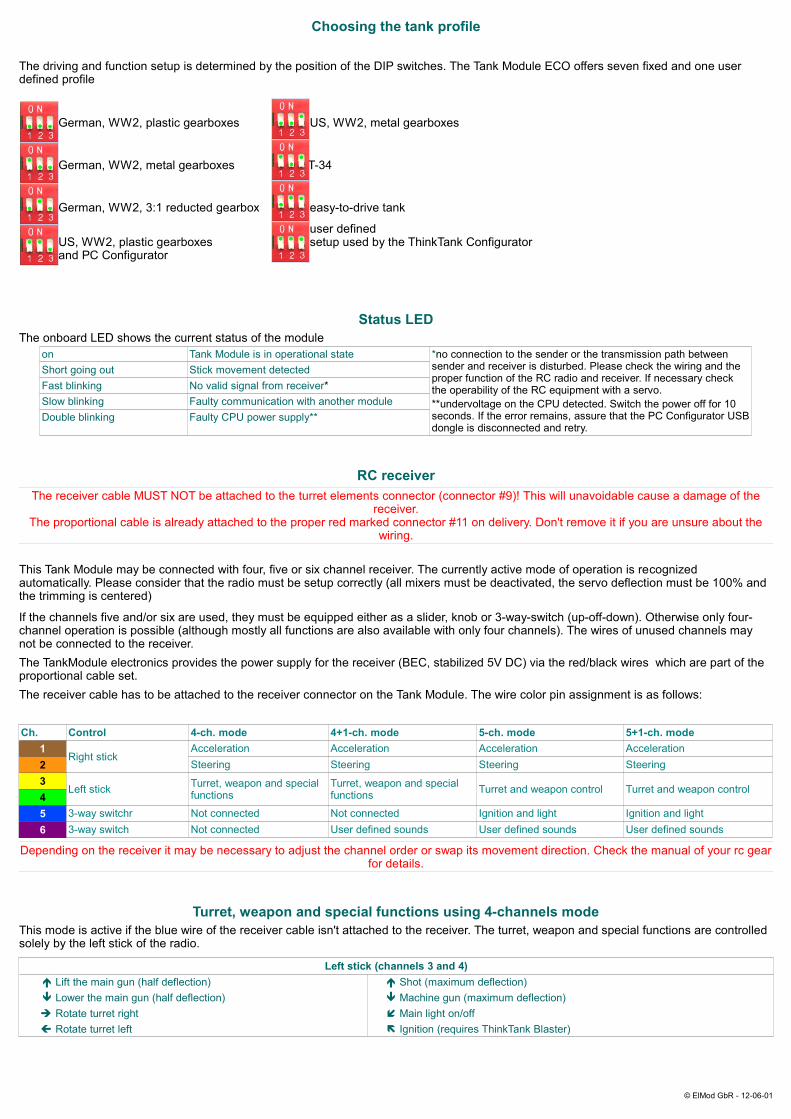
Choosing the tank profile
The driving and function setup is determined by the position of the DIP switches. The Tank Module ECO offers seven fixed and one user defined profile
German, WW2, plastic gearboxes US, WW2, metal gearboxes
German, WW2, metal gearboxes T-34
German, WW2, 3:1 reducted gearbox easy-to-drive tank
user definedUS, WW2, plastic gearboxes setup used by the ThinkTank Configurator and PC Configurator
Status LEDThe onboard LED shows the current status of the module
on Tank Module is in operational state *no connection to the sender or the transmission path between sender and receiver is disturbed. Please check the wiring and the proper function of the RC radio and receiver. If necessary check the operability of the RC equipment with a servo.**undervoltage on the CPU detected. Switch the power off for 10 seconds. If the error remains, assure that the PC Configurator USB dongle is disconnected and retry.
Short going out Stick movement detectedFast blinking No valid signal from receiver*Slow blinking Faulty communication with another moduleDouble blinking Faulty CPU power supply**
RC receiverThe receiver cable MUST NOT be attached to the turret elements connector (connector #9)! This will unavoidable cause a damage of the
receiver.The proportional cable is already attached to the proper red marked connector #11 on delivery. Don't remove it if you are unsure about the
wiring.
This Tank Module may be connected with four, five or six channel receiver. The currently active mode of operation is recognized automatically. Please consider that the radio must be setup correctly (all mixers must be deactivated, the servo deflection must be 100% and the trimming is centered)
If the channels five and/or six are used, they must be equipped either as a slider, knob or 3-way-switch (up-off-down). Otherwise only four-channel operation is possible (although mostly all functions are also available with only four channels). The wires of unused channels may not be connected to the receiver.The TankModule electronics provides the power supply for the receiver (BEC, stabilized 5V DC) via the red/black wires which are part of the proportional cable set.The receiver cable has to be attached to the receiver connector on the Tank Module. The wire color pin assignment is as follows:
Ch. Control 4-ch. mode 4+1-ch. mode 5-ch. mode 5+1-ch. mode1
Right stickAcceleration Acceleration Acceleration Acceleration
2 Steering Steering Steering Steering3
Left stick Turret, weapon and special functions
Turret, weapon and special functions Turret and weapon control Turret and weapon control
45 3-way switchr Not connected Not connected Ignition and light Ignition and light6 3-way switch Not connected User defined sounds User defined sounds User defined sounds
Depending on the receiver it may be necessary to adjust the channel order or swap its movement direction. Check the manual of your rc gear for details.
Turret, weapon and special functions using 4-channels modeThis mode is active if the blue wire of the receiver cable isn't attached to the receiver. The turret, weapon and special functions are controlled solely by the left stick of the radio.
Left stick (channels 3 and 4)é Lift the main gun (half deflection) é Shot (maximum deflection)ê Lower the main gun (half deflection) ê Machine gun (maximum deflection)è Rotate turret right Main light on/offç Rotate turret left Ignition (requires ThinkTank Blaster)
© ElMod GbR - 12-06-01

Turret, weapon and special functions using 5-channels modeThis mode is active if the blue wire of the receiver cable is attached to the receiver. The turret and weapon functions are controlled by the left stick of the radio, ignition and light is mapped to the 3-way switch connected to channel 5 of the radio.
Left stick (channels 3 and 4) Switch (channel 5)é Lift the main gun (half deflection) é Shot (max. deflection) é Ignition (requires ThinkTank Blaster)ê Lower the main gun (half deflection) ê Machine gun (max. deflection) ê Main light on/offè Rotate turret rightç Rotate turret left
User defined soundsIf a ThinkTank Blaster is connected to this ThankModule, up to two user defined sounds may be activated optionally by the user. To use this feature, the violet wire of the receiver cable has to be attached to the 6th channel of the receiver .The samples are activated by switching the corresponding control in the radio to upper most (user sample 1) or lower most (user sample 2) position. The playback may be aborted by moving the switch in the opposite direction.
Under voltage protectionThe TankModule features an under voltage protection to protect the batteries from deep discharge. On delivery the threshold voltage is set to 6 volts for 7.2V NiMh/NiCd batteries. If the voltage drops below 6 volts, the tank stops and the main light starts to blink. In this case replace or recharge the battery.
Fuse for turret elementsThe element #2 on the PCB is a safety fuse for the turret motors. The fuse blows if the total current of the turret motors excesses 2 amps which never happens under normal conditions. In this case no turret function is given (turret rotation, elevation, shot) and all lights are off. Check the wiring for shortcuts and the mechanics for blockages. Replace the damaged fuse with a new one. The fuses are available as spare parts in our shop.
Nicht geeignet für Kinder unter 14 Jahren. Not suitable for Children under 14 years.Ne convient pas pour des enfants de moins de 14 ans. Niet geschikt voor kinderen onder de 14 jaar.
ElMod Thomas Kusch, M. Sc. & Jürgen K. Huber GbRSteinenbergstr. 24D-72622 Nürtingen
ElMod Th. Kusch, M.Sc. & Jürgen K. Huber GbR [email protected] http://www.elmod.eu
© ElMod GbR - 12-06-01