thinkserver smart grid technology user guide
TRANSCRIPT

ThinkServer Smart Grid Technology User Guide
1
Table of Contents
Statement ................................................................................................................................................................................................................................ 4
Trademark and Copyright ........................................................................................................................................................................................................ 5
Chapter 1. Product Overview .................................................................................................................................................................................................. 6
1.1 Product Introduction .......................................................................................................................................................................................................... 6
1.2 Structure and Composition of the Product ........................................................................................................................................................................ 7
1.3 Operating Environment of the Product .............................................................................................................................................................................. 8
1.4 Major Functions of the Product ......................................................................................................................................................................................... 8
Chapter 2. Planning and Deployment ................................................................................................................................................................................... 10
2.1 Deployment Planning ...................................................................................................................................................................................................... 10
2.1.1 Centralized Power Consumption Management for Multiple Servers in LAN ....................................................................................................... 10
2.1.2 Centralized Management of Multiple Servers across Internet.............................................................................................................................. 11
2.1.3 Server Time Synchronization Requirements ........................................................................................................................................................ 11
2.1.4 Port Usage Requirements of Smart Grid Server .................................................................................................................................................. 11
2.1.5 Network Connectivity Requirements for Data Collection ..................................................................................................................................... 12
2.1.6 Performance Data Collection Requirements of Windows Servers ...................................................................................................................... 12
2.2 Installation ....................................................................................................................................................................................................................... 12
2.2.1 Installation for Windows ....................................................................................................................................................................................... 12
2.2.2 Installation for Linux ............................................................................................................................................................................................. 13
2.3 Uninstall ........................................................................................................................................................................................................................... 14
2.3.1 Uninstallation for Windows .................................................................................................................................................................................. 14
2.3.2 Uninstallation for Linux ........................................................................................................................................................................................ 14
Chapter 3. Product Instructions ............................................................................................................................................................................................. 15
3.1 Access to System ............................................................................................................................................................................................................ 15
3.1.1 First Login ............................................................................................................................................................................................................ 15
3.1.2 Exit the System .................................................................................................................................................................................................... 16
3.2 Home ............................................................................................................................................................................................................................... 16
3.2.1 Power Consumption of the Day ........................................................................................................................................................................... 16
3.2.2 Device Overview .................................................................................................................................................................................................. 16
3.2.3 Power Consumption Ranking in Last 1 Hour....................................................................................................................................................... 18
3.2.4 Event List ............................................................................................................................................................................................................. 18
3.2.5 Device Status ....................................................................................................................................................................................................... 18
3.3 System Configuration ...................................................................................................................................................................................................... 19
3.3.1 Activate Software ................................................................................................................................................................................................. 19
3.3.2 Global Configuration ............................................................................................................................................................................................ 19
3.3.3 User Management ............................................................................................................................................................................................... 19

4
3.4 Device Discovery ............................................................................................................................................................................................................. 19
3.4.1 Auto Discovery ..................................................................................................................................................................................................... 20
3.4.2 Batch Import ........................................................................................................................................................................................................ 20
3.4.3 Add a Single Device............................................................................................................................................................................................. 20
3.5 Device Management........................................................................................................................................................................................................ 21
3.5.1 Device Information Lookup .................................................................................................................................................................................. 21
3.5.2 Status Management............................................................................................................................................................................................. 23
3.5.3 Editing .................................................................................................................................................................................................................. 25
3.5.4 Deleting ................................................................................................................................................................................................................ 25
3.5.5 Import/Export ....................................................................................................................................................................................................... 26
3.5.6 Power Consumption Management ...................................................................................................................................................................... 26
3.5.7 Performance Management .................................................................................................................................................................................. 26
3.6 Power Consumption Monitoring and Learning ................................................................................................................................................................ 26
3.6.1 Power Consumption Monitoring .......................................................................................................................................................................... 26
3.6.2 Power Consumption Learning ............................................................................................................................................................................. 27
3.7 Power Consumption Control ........................................................................................................................................................................................... 28
3.7.1 Management Policy ............................................................................................................................................................................................. 28
3.7.2 Policy Description ................................................................................................................................................................................................ 29
3.7.3 Policy Operating Status ....................................................................................................................................................................................... 30
3.7.4 Emergency Plan .................................................................................................................................................................................................. 31
3.8 Performance Management .............................................................................................................................................................................................. 32
3.8.1 Performance Monitoring ...................................................................................................................................................................................... 32
3.8.2 Threshold Setting ................................................................................................................................................................................................. 33
3.9 Statistic Ranking .............................................................................................................................................................................................................. 34
3.9.1 Power Consumption Ranking .............................................................................................................................................................................. 34
3.9.2 Performance Ranking .......................................................................................................................................................................................... 34
3.10 Operation Report ........................................................................................................................................................................................................... 35
3.10.1 Report Functions ............................................................................................................................................................................................... 35
3.10.2 Report Explained ............................................................................................................................................................................................... 35
3.11 Event Management ........................................................................................................................................................................................................ 38
3.11.1 Event List ........................................................................................................................................................................................................... 38
3.11.2 Forwarding Configuration................................................................................................................................................................................... 38
Chapter 4. Frequently Asked Questions ................................................................................................................................................................................ 40
4.1 It's Unable to See Power Consumption Data in Smart Grid ............................................................................................................................................ 40
4.2 It's Unable to See Performance Data under Linux Host.................................................................................................................................................. 40
4.3 It's Unable to See Performance Data in Windows Host .................................................................................................................................................. 41

3
4.4 Unable to Discover the Host ............................................................................................................................................................................................ 41
4.5 Unable to Discover Any Device via Auto Discovery under Linux .................................................................................................................................... 41
4.6 When Adding a Device, It's Prompted that the Device is Unable to Perform Power Consumption Control.................................................................... 42
4.7 Event Forwarding Configuration ...................................................................................................................................................................................... 42
Appendix 1: Glossary and Abbreviations ............................................................................................................................................................................... 44
Appendix 2: Smart Grid Event Type Description ................................................................................................................................................................... 45

4
Statement
Thank you for choosing Lenovo.
This manual is designed to help you use Lenovo servers (hereafter referred to "this product") properly, and before you install and run this product for the first time, make sure carefully read all materials provided with the product, especially the precautions provided in this manual. That will help you to use this product in a better and safer manner. Please store this manual appropriately for future reading.
The description in this manual does not represent any description for the specification, software and hardware configurations of the product. For the actual specifications and configuration of this product, please see related agreements, packing lists, description files for product specifications and configuration, or you can consult the seller of this product.
If you install, use or maintain this product incorrectly, or deviate from the instructions and requirements described in this manual, or if the product is repaired or modified by non-Lenovo authorized technicians, Lenovo shall not assume any liability for the damages.
The pictures, graphs, charts and illustrations provided in this manual are for explanation and description only, and might be different from the actual products. In addition, the actual product specification and configuration may vary depending on the demand, thus creating a difference from this manual. All data should refer to the actual products.
The information regarding non-Lenovo website mentioned in this manual is provided for your convenience, but the information in such websites is neither a part of Lenovo product information nor a part of Lenovo service. Lenovo shall not provide any guaranty for the accuracy and usefulness of such websites and information. All the risks arise from using these websites will be the undertaken by your own.
This manual does not necessarily indicate that Lenovo provides any warranty, whether express or implied, for its products and services, including but not limited to the suitability, safety, merchantability and fitness for particular purpose of the products recommended in this manual. Any guaranty and warranty commitment of this product and related services shall be carried out according to appropriate agreements or the terms and conditions of the standard product warranty service. To the maximum allowable range of laws and regulations, no liability shall be taken by Lenovo for any damages caused by using or being unable to use this product, including but not limited to the direct or indirect personal damage, loss of commercial profit, interruption of business, loss of business information or any other losses.
The software mentioned in the document is provided based on the license agreement, and can only be used according to the terms of the license agreement. The provided software could be different from the retail version, and may not include the user manual or all program functionality. If you use the software provided with this product on the other products, or if you use software not coming with this product or any software other than the special software verified and recommended by Lenovo on this product, we shall not provide any guaranty for its reliability.
The performance data included in the document is determined based on the specific environment, and is provided for illustration only. The data acquired under different environments can be substantially different. The user of the document should verify the data available under the specific environment.
We have collated and checked this manual carefully, but cannot guarantee the manual to be free of any error and omission. In order to provide better services, we may improve and/or modify the information regarding the software and hardware of the product described in this manual and the contents of the manual at any time without prior notice. If the product you are using is different from the information in this manual, or if you wish to obtain the latest information or have any questions or suggestions, please feel free to call us or visit Lenovo service website for inquiry.
5
Trademark and Copyright
The text and logo of "Legend", "Lenovo", "Lenovo 联想", "ThinkServer", and "For Those Who Do" are trademarks and registered trademarks of Lenovo
Corporation subsidiaries in China and/or other countries and regions.
"Intel", "Intel Inside", and "Pentium" are trademarks or registered trademarks of Intel Corporation.
"Microsoft", "Windows", "Windows XP" and "Windows NT" are trademarks or registered trademarks of Microsoft Corporation.
Other company, product or service names may be trademarks or service marks of other companies.
The OEM software mentioned in the manual is provided based on the terms and conditions of the end-user license agreement, and can only be used and copied according to the terms and conditions of the end-user license agreement.
Copyright © 1999-2012 Lenovo (Beijing) Co., Ltd. All rights reserved.
The manual is protected under the copyright laws; without the prior written authorization of Lenovo, no person shall in any way replicate, transcribe, delete the entire or any part of the manual, or compile it into machine-readable format, or in any way store it in a index system, transfer it by wired or wireless network, or in any way translate it into any languages.
Lenovo (Beijing) Co., Ltd.
6
Chapter 1. Product Overview
1.1 PRODUCT INTRODUCTION
Lenovo ThinkServer Smart Grid Technology (hereafter referred to Smart Grid) is a software (not free) associated with Lenovo ThinkServer servers, which can monitor and manage the power consumption of several Lenovo ThinkServer servers in the corporation network, IDC and so on.
This product is a combination of IT (Information Technology) management and ET (Energy Technology) management, which can provide centralized remote management of power consumption of the servers supporting Intel Power Node Manager technology.
The process which Smart Grid manages the device power consumption includes: Discover/Import a Device Monitor the Power Consumption of a Device Learn the Characteristics of the Power Consumption Changes Implement Energy-saving Policies Analyze the Energy-saving Conditions Power Consumption Policy Adjustment Suggestion. This process makes the closed loop full-process management for device power consumption into a reality, so that the most appropriate energy-saving policy can be determined for each device in order to lower its power consumption.
Smart Grid applies server/browser architecture and is easy to operate, while collecting device power consumption data and performance data can be done without installing any agent software in the managed servers. This product simply needs to be installed on the server end and the end-users may use the product through their web browsers.
Reducing the device power consumption, Smart Grid can effectively reduce the power consumption of the whole machine room, in order to realizing the energy-saving and emission-reduction of green IT.
The new features in Smart Grid include:
1. Monitors the Power Consumption of Device (Group)
Provide a real-time power consumption monitoring function for the device (group), which allows you to master the real-time power consumption at any time.
Support an auto/manual power consumption control for the device. This system recommends a group of default power consumption control policies on the basis of existing device power consumption condition; in addition, users can also set different power consumption values for different periods as needed, in order to refine the management of energy-saving policies. Enable the system to control the device power consumption by activating the power consumption control policy.
Support the power consumption control based on device group. When an power consumption value is set for a certain group, the system will adjust the power consumption policy for each device automatically according to the requirement of devices in the group, balancing the performance of each device in the group while ensuring the group power consumption value not exceed the threshold, so as to guarantee the well business operations.
2. Collects the Device Performance Agentless
The traditional network management system requires an agent software to be installed in the business host to collect performance data, this will cause new potential troubles to the business host because the agent software itself may have many uncertainties and security problems, moreover, the installation and maintenance of this agent software will need a big cost for large-scale machine room.
Smart Grid supports the collection of CPU and memory utilization without any agent.
Avoids all impacts on business caused by installing the agent software.
Eliminates the installation, upgrade and maintenance costs due to the agent.
Improves the security of business host.
3. Saves Power without Compromising the Performance
Smart Grid can not only saves the power consumption, but also comprehensively masters the device performance and faults, so as to ensuring business functioning well while saving the energy, and then realizing the purpose of safe energy-saving.
Monitor the device power consumption while performing the centralized monitoring to the device performance and events.
You can set the performance thresholds as you want.
Auto mail forwarding can be configured in case of important events.

7
4. Emergency Responses
When an emergency occurs (such as natural disasters and unexpected power-off), appropriate actions shall be taken to shut down the device normally and write data into the disk, in this case, it is the crucial that how to extend the operating time of device when it is powered by UPS.
Smart Grid provides immediate emergency plans for "Emergency State", and reduces the device power consumption by limiting it to the lowest level, so as to extend the operating time and ensure the data is archived safely when an emergency occurs.
5. Powerful Auxiliary Functions
This system provides the analysis ability based on the power consumption management, in order to help users analyze the device power-savings.
It helps users to determine the suitability of applying policies, pick out the devices which need a policy adjustment or need to get back to the learning stage and detail the energy-saving process.
It provides multi-dimensional power consumption statistics and ranks, in order to help users to learn the relative power consumption and historical power consumption of each device.
1.2 STRUCTURE AND COMPOSITION OF THE PRODUCT
Smart Grid software consists of the following components:
1. Smart Grid server
2. Client browser (provided by the users themselves)
The management mode of Smart Grid is shown below:
8
1.3 OPERATING ENVIRONMENT OF THE PRODUCT
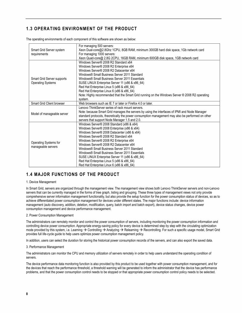
The operating environments of each component of this software are shown as below:
Smart Grid Server system requirements
For managing 500 servers: Xeon [email protected] 1CPU, 8GB RAM, minimum 300GB hard disk space, 1Gb network card For managing 1000 servers: Xeon Quad-core@ 2.8G 2CPU, 16GB RAM, minimum 600GB disk space, 1GB network card
Smart Grid Server supports Operating Systems
Windows Server® 2008 R2 Standard x64 Windows Server® 2008 R2 Enterprise x64 Windows Server® 2008 R2 Datacenter x64 Windows® Small Business Server 2011 Standard Windows® Small Business Server 2011 Essentials SUSE LINUX Enterprise Server 11 (x86 & x86_64) Red Hat Enterprise Linux 5 (x86 & x86_64) Red Hat Enterprise Linux 6 (x86 & x86_64) Note: Highly recommended that the Smart Grid running on the Windows Server ® 2008 R2 operating system.
Smart Grid Client browser Web browsers such as IE 7 or later or Firefox 4.0 or later.
Model of manageable server
Lenovo ThinkServer series of rack mount servers. Note: because Smart Grid manages the servers by using the interfaces of IPMI and Node Manager standard protocols, theoretically the power consumption management may also be performed on other servers that support Node Manager 1.5 and 2.0.
Operating Systems for manageable servers
Windows Server® 2008 Standard (x86 & x64) Windows Server® 2008 Enterprise (x86 & x64) Windows Server® 2008 Datacenter (x86 & x64) Windows Server® 2008 R2 Standard x64 Windows Server® 2008 R2 Enterprise x64 Windows Server® 2008 R2 Datacenter x64 Windows® Small Business Server 2011 Standard Windows® Small Business Server 2011 Essentials SUSE LINUX Enterprise Server 11 (x86 & x86_64) Red Hat Enterprise Linux 5 (x86 & x86_64) Red Hat Enterprise Linux 6 (x86 & x86_64)
1.4 MAJOR FUNCTIONS OF THE PRODUCT
1. Device Management
In Smart Grid, servers are organized through the management view. The management view shows both Lenovo ThinkServer servers and non-Lenovo servers that can be currently managed in the forms of tree graph, listing and grouping. These three types of management views not only provide comprehensive server information management functionality, but also provide the setup function for the power consumption status of devices, so as to achieve differentiated power consumption management for devices under different states. The major functions include: device information management (auto discovery, addition, deletion, modification, query, batch import and batch export), device status changes, device power consumption management and device performance management.
2. Power Consumption Management
The administrators can remotely monitor and control the power consumption of servers, including monitoring the power consumption information and controlling device power consumption. Appropriate energy-saving policy for every device is determined step by step with the circulating optimization mode provided by this system, i.e. Learning Controlling Analyzing Relearning Recontrolling. For such a specific usage model, Smart Grid provides full life-cycle guide to help users optimize power consumption management policy.
In addition, users can select the duration for storing the historical power consumption records of the servers, and can also export the saved data.
3. Performance Management
The administrators can monitor the CPU and memory utilization of servers remotely in order to help users understand the operating condition of servers.
The device performance data monitoring function is also provided by this product to be used together with power consumption management, and for the devices that reach the performance threshold, a threshold warning will be generated to inform the administrator that the device has performance problems, and that the power consumption control needs to be stopped or that appropriate power consumption control policy needs to be selected.
9
4. Analysis and Report on Power Consumption
To achieve true cost saving, this system provides multi-dimensional power consumption rankings and power consumption analysis reports, which can help users analyze the power consumption status of all devices, discover the device with highest power consumption, and filter out the devices with potential problems in energy saving policy which may need adjustment.
5. Server Event Management
Smart Grid records and saves various event information generated by servers, which enables abundant event management functions.
Event information mainly include DCM events, collector events, active policy events and threshold events.
The administrators can perform operations on all saved event information, such as browsing, searching, exporting and so on.
The administrators can also set forwarding policies for events and send the specified type of alarms to the related maintainer by Email.
10
Chapter 2. Planning and Deployment
2.1 DEPLOYMENT PLANNING
Smart Grid can support flexible web deployment plans, and uses entire or any part of the product functionality based on the scenarios. For the application scenarios of server devices that only need power consumption monitoring, the managed servers need to support Intel Intelligent Power Node Manager technology, and its BMC IP network is connected to Smart Grid Server network. For the application scenarios of server devices that require power consumption monitoring and performance monitoring simultaneously, Smart Grid server must also be able to get access to the operating system of managed server through network.
2.1.1 CENTRALIZED POWER CONSUMPTION MANAGEMENT FOR MULTIPLE SERVERS IN LAN
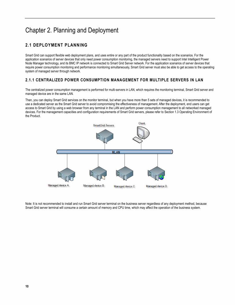
The centralized power consumption management is performed for multi-servers in LAN, which requires the monitoring terminal, Smart Grid server and managed device are in the same LAN.
Then, you can deploy Smart Grid services on the monitor terminal, but when you have more than 5 sets of managed devices, it is recommended to use a dedicated server as the Smart Grid server to avoid compromising the effectiveness of management. After the deployment, end users can get access to Smart Grid by using a web browser from any terminal in the LAN and perform power consumption management to all networked managed devices. For the management capacities and configuration requirements of Smart Grid servers, please refer to Section 1.3 Operating Environment of the Product.
Note: It is not recommended to install and run Smart Grid server terminal on the business server regardless of any deployment method, because Smart Grid server terminal will consume a certain amount of memory and CPU time, which may affect the operation of the business system.

11
2.1.2 CENTRALIZED MANAGEMENT OF MULTIPLE SERVERS ACROSS INTERNET
Smart Grid can also provide power consumption management to multiple servers when spanning Internet. In this scenario, the corporation network is divided into two, i.e. LAN and DMZ zone (a large corporation has Extranet and Intranet DMZ zones located in two machine rooms separately) where the application servers for Internet such as mail server and Web server are located. Every server in DMZ zone is provided with two IP addresses, LAN address and Internet address, and connects multiple machine rooms by special cables.
Then, Smart Grid server software is installed on a dedicated server in LAN. The end users can monitor the power consumption of servers in LAN and DMZ zone with the terminal login system in internal LAN, DMZ or Internet, when the network parameters are properly configured.
To ensure that Smart Grid severs can communicate with the servers in DMZ zone, configure the intranet firewall properly and allow normal communication between the Smart Grid servers and the BMC module of servers in DMZ zone. For the network requirements of this product, please refer to Section 2.1.3.
If you want to monitor devices by Internet, it is recommended that you can access Intranet by VPN first and then perform operations.
Tips: For safety concern, it is not recommended for users to deploy Smart Grid server on Internet.
2.1.3 SERVER TIME SYNCHRONIZATION REQUIREMENTS
Smart Grid server and the managed server need to maintain synchronization in time, so it is recommended to select a server in the network as a time server (NTP server) and synchronize the times of other servers with the time of NTP server.
2.1.4 PORT USAGE REQUIREMENTS OF SMART GRID SERVER
The operation of Smart Grid software requires three TCP ports (TCP port numbers of 6443, 8688 and 8888). Therefore, before the installation, please make sure that the TCP network ports of the sever are not occupied by other software.
12
2.1.5 NETWORK CONNECTIVITY REQUIREMENTS FOR DATA COLLECTION
Smart Grid performs agentless data collection for the power consumption, CPU usage and memory usage. For a device that needs performance management, please make sure that the operating system of the device is within the manageable range by Smart Grid, and that the IP network of the operating system has already been connected to the Smart Grid server and the account of the operating system used for collection can successfully log into the operating system.
The network requirements for collecting power consumption and performance data of managed devices are as follows:
For power consumption data collecting: the BMC IPMI port of the managed devices (UDP Port 623) can communicate properly by network.
For performance data collecting: if managed devices apply Linux operating system, SSH port (default TCP Port 22) can communicate properly by network; if managed devices apply Windows operating system, DCOM port (default TCP Port 135) is able to be connected properly via network. If failed, you can modify the firewall policy or the default ports of SSH or DCOM.
2.1.6 PERFORMANCE DATA COLLECTION REQUIREMENTS OF WINDOWS SERVERS
When Smart Grid is collecting the performance data of servers with Windows 2008 or later, the operating systems installed in managed devices require the following necessary operations in order to collect the performance data of Windows servers properly due to the stricter security requirements of Windows 2008 or later. The detailed process is as follows:
(1) If Smart Grid is installed on the Windows operating system, the OS Username at Probe Configuration must be 'administrator' when add the managed devices;
(2) If Smart Grid is installed on the Linux operating system, you need to copy wmi.bat and wimconfig.ps1 from toos folder in installation CD to the same directory of managed devices, double-click wmi.bat ,input two parameters: managerIP (IP of Smart Grid server) and probeUserName (OS username of the managed devices), then press Enter.
2.2 INSTALLATION
Smart Grid uses server/browser architecture design, only the installation of Smart server program is needed and the end-users can get access to this product through web browsers.
In the Smart Grid installation CD, the included installation packages of three Smart Grid versions are:
(1) smartgrid_32.exe is the Smart Grid installer for Windows 32-bit;
(2) smartgrid_64.exe is the Smart Grid installer for Windows 64-bit;
(3) smartgrid.zip is the Smart Grid installer compatible for both Linux 32-bit and 64-bit.
2.2.1 INSTALLATION FOR WINDOWS
After putting the Smart Grid installation CD into the CD-ROM, the installer will run automatically, and the step-by-step instruction will help you complete the installation process.
Note: if the installer does not run automatically after the Smart Grid installation CD is placed into the CD-ROM, then enter the CD directory and click "setup.exe" to launch the installation wizard.

13
2.2.2 INSTALLATION FOR LINUX
1. After putting Smart Grid installation CD into the CD-ROM, enter the installation directory (e.g. cd/mnt/cdrom), and execute the following installation commands:
chmod +x install.sh
./install.sh
The program will be installed to /opt/smartgrid by default, and if you want to specify an installation directory (for example: /opt/sgt), execute the following command:
./install.sh /opt/sgt
2. Install ipmiutil and select a suitable RPM installation package based on the Linux version, and then execute the following command:
rpm -i ipmiutil-2.7.8-1_rhel6.x86_64.rpm
On servers with Red Hat Linux 6.1 or later, the packages required for running Smart Grid are not installed in the operating system by default. These packages include:
1)ld-linux.so.2
2)libxml2.so.2
3)libpq.so.5
4)libtermcap.so.2
5)libreadline.so.5
The procedure to install the above packages is as follows:
The yum source must be configured before you perform installation with yum, while you can use DVD disk or ISO file as the local yum source when networking is unavailable. The details are as follows:
(1) Create a directory for storing ISO file (/repo/iso) and a directory for mounting ISO file (/repo/rhel6)
# mkdir /repo/iso
# mkdir /repo/rhel6
If you have a ready ISO file, you can upload it to /repo/iso.
(2) If installing with a DVD disk (automatically mapped under /dev/cdrom after inserting the disk into the server), then create an ISO file
# cp /dev/cdrom /repo/iso/rhel-server-6.0-x86_64-dvd.iso
or
# dd if=/dev/cdrom of=/repo/iso/rhel-server-6.0-x86_64-dvd.iso
(3) Mount a ISO file
# mount -t iso9660 -o loop /repo/iso/rhel-server-6.0-x86_64-dvd.iso /repo/rhel6
# df -h File System Capacity Used Free Used %% Mounting point /dev/sda5 97G 5.8G 86G 7% / tmpfs 1.9G 272K 1.9G 1% /dev/shm /dev/loop0 3.2G 3.2G 0 100% /repo/rhel6
(4) Ensure related yum packages are installed in the system
# rpm -qa |grep yum yum-3.2.27-14.el6.noarch yum-utils-1.1.26-11.el6.noarch yum-rhn-plugin-0.9.1-5.el6.noarch PackageKit-yum-0.5.8-13.el6.x86_64 yum-metadata-parser-1.1.2-14.1.el6.x86_64 PackageKit-yum-plugin-0.5.8-13.el6.x86_64
They may have different versions, and if anything is missing, please install it by yourself (most of these packages are installed by default).
14
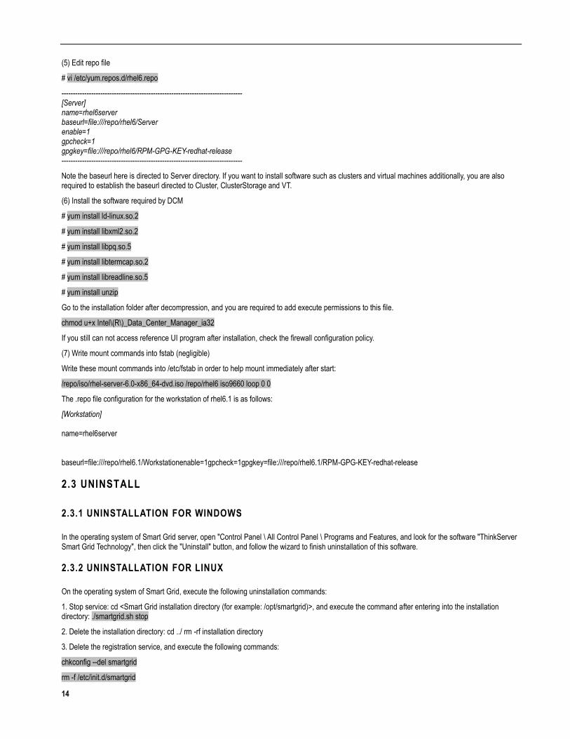
(5) Edit repo file
# vi /etc/yum.repos.d/rhel6.repo
------------------------------------------------------------------------------- [Server] name=rhel6server baseurl=file:///repo/rhel6/Server enable=1 gpcheck=1 gpgkey=file:///repo/rhel6/RPM-GPG-KEY-redhat-release -------------------------------------------------------------------------------
Note the baseurl here is directed to Server directory. If you want to install software such as clusters and virtual machines additionally, you are also required to establish the baseurl directed to Cluster, ClusterStorage and VT.
(6) Install the software required by DCM
# yum install ld-linux.so.2
# yum install libxml2.so.2
# yum install libpq.so.5
# yum install libtermcap.so.2
# yum install libreadline.so.5
# yum install unzip
Go to the installation folder after decompression, and you are required to add execute permissions to this file.
chmod u+x Intel\(R\)_Data_Center_Manager_ia32
If you still can not access reference UI program after installation, check the firewall configuration policy.
(7) Write mount commands into fstab (negligible)
Write these mount commands into /etc/fstab in order to help mount immediately after start:
/repo/iso/rhel-server-6.0-x86_64-dvd.iso /repo/rhel6 iso9660 loop 0 0
The .repo file configuration for the workstation of rhel6.1 is as follows:
[Workstation] name=rhel6server baseurl=file:///repo/rhel6.1/Workstationenable=1gpcheck=1gpgkey=file:///repo/rhel6.1/RPM-GPG-KEY-redhat-release
2.3 UNINSTALL
2.3.1 UNINSTALLATION FOR WINDOWS
In the operating system of Smart Grid server, open "Control Panel \ All Control Panel \ Programs and Features, and look for the software "ThinkServer Smart Grid Technology", then click the "Uninstall" button, and follow the wizard to finish uninstallation of this software.
2.3.2 UNINSTALLATION FOR LINUX
On the operating system of Smart Grid, execute the following uninstallation commands:
1. Stop service: cd <Smart Grid installation directory (for example: /opt/smartgrid)>, and execute the command after entering into the installation directory: ./smartgrid.sh stop
2. Delete the installation directory: cd ../ rm -rf installation directory
3. Delete the registration service, and execute the following commands:
chkconfig --del smartgrid
rm -f /etc/init.d/smartgrid
15
Chapter 3. Product Instructions
3.1 ACCESS TO SYSTEM
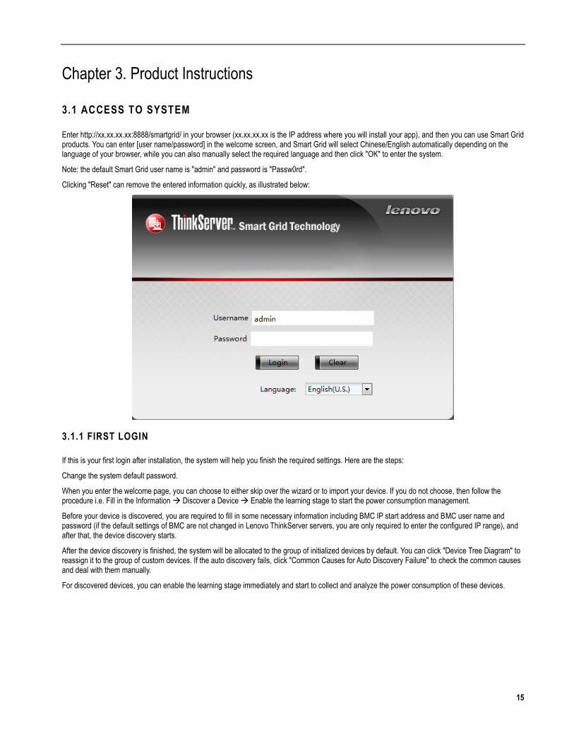
Enter http://xx.xx.xx.xx:8888/smartgrid/ in your browser (xx.xx.xx.xx is the IP address where you will install your app), and then you can use Smart Grid products. You can enter [user name/password] in the welcome screen, and Smart Grid will select Chinese/English automatically depending on the language of your browser, while you can also manually select the required language and then click "OK" to enter the system.
Note: the default Smart Grid user name is "admin" and password is "Passw0rd".
Clicking "Reset" can remove the entered information quickly, as illustrated below:
3.1.1 FIRST LOGIN
If this is your first login after installation, the system will help you finish the required settings. Here are the steps:
Change the system default password.
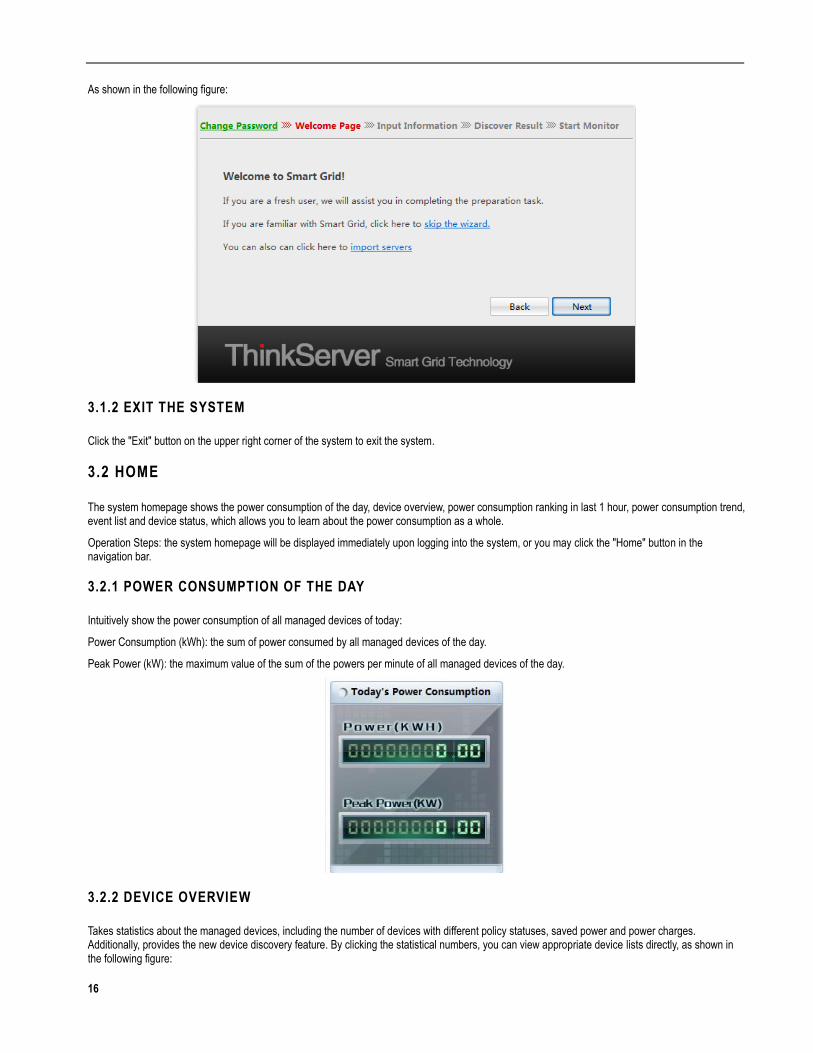
When you enter the welcome page, you can choose to either skip over the wizard or to import your device. If you do not choose, then follow the procedure i.e. Fill in the Information Discover a Device Enable the learning stage to start the power consumption management.
Before your device is discovered, you are required to fill in some necessary information including BMC IP start address and BMC user name and password (if the default settings of BMC are not changed in Lenovo ThinkServer servers, you are only required to enter the configured IP range), and after that, the device discovery starts.
After the device discovery is finished, the system will be allocated to the group of initialized devices by default. You can click "Device Tree Diagram" to reassign it to the group of custom devices. If the auto discovery fails, click "Common Causes for Auto Discovery Failure" to check the common causes and deal with them manually.
For discovered devices, you can enable the learning stage immediately and start to collect and analyze the power consumption of these devices.
16
As shown in the following figure:
3.1.2 EXIT THE SYSTEM
Click the "Exit" button on the upper right corner of the system to exit the system.
3.2 HOME
The system homepage shows the power consumption of the day, device overview, power consumption ranking in last 1 hour, power consumption trend, event list and device status, which allows you to learn about the power consumption as a whole.
Operation Steps: the system homepage will be displayed immediately upon logging into the system, or you may click the "Home" button in the navigation bar.
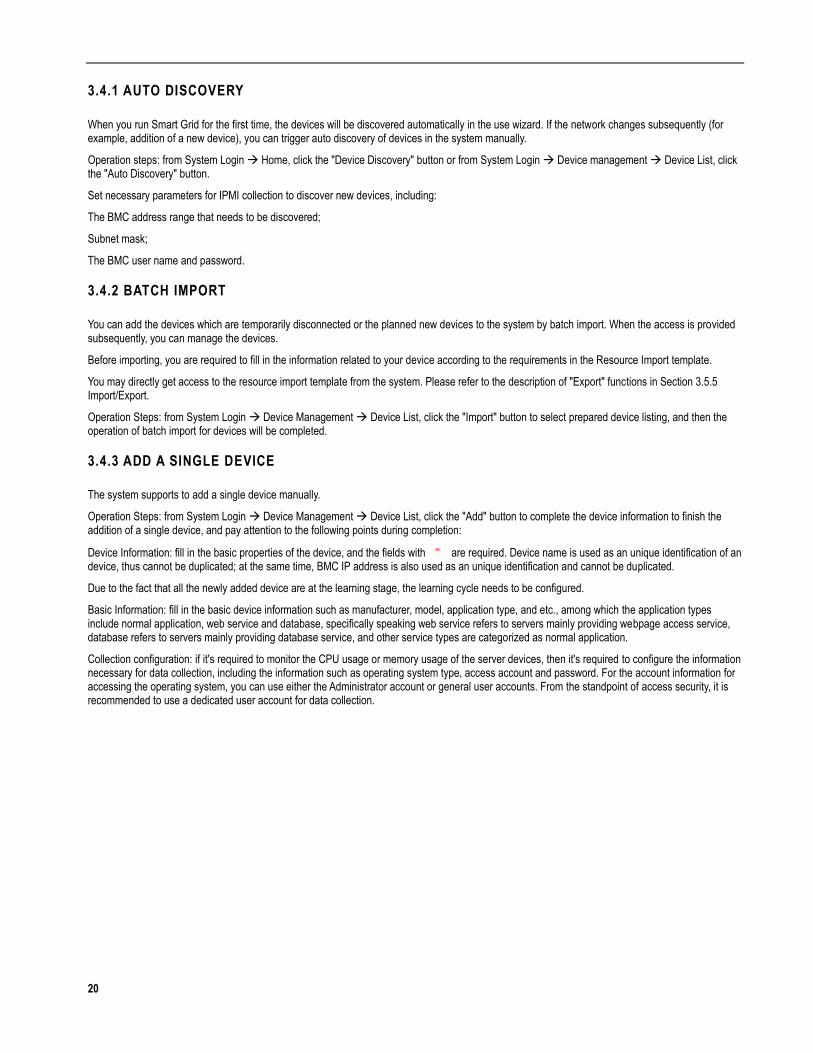
3.2.1 POWER CONSUMPTION OF THE DAY
Intuitively show the power consumption of all managed devices of today:
Power Consumption (kWh): the sum of power consumed by all managed devices of the day.
Peak Power (kW): the maximum value of the sum of the powers per minute of all managed devices of the day.
3.2.2 DEVICE OVERVIEW
Takes statistics about the managed devices, including the number of devices with different policy statuses, saved power and power charges. Additionally, provides the new device discovery feature. By clicking the statistical numbers, you can view appropriate device lists directly, as shown in the following figure:

17
Device Discovery
A rapid functionality portal, which is consistent with Device Discovery under Device Management, please refer to the description in Section 3.4 Device Discovery for details.
Device Statistics
Based on the number of the devices and the number of the device groups, 6-dimensional statistics is done. Click on the number to see a specific device, please refer to the description in Section 3.5.2 Status Management for detailed status characteristics.
Energy-saving Statistics
The amount of energy saved after enabling the energy saving policy will be converted to the power saved, and later the power charge that can be saved will be calculated based on the set electricity unit price (the electricity unit price can be configured by clicking the "Set the Electricity Price" button and enter the setting screen, please refer to the description in Section 3.3.2 Global Configuration for details).
The power saved refers to the difference between the power consumption of all managed server devices running under empirical power and the power consumption of all server devices under actual running and the value is the cumulative value of power saved by all servers since from the installation of the Smart Grid software. The software product will record the data of power saved by the server devices every day, even if a server device is deleted from the software, this cumulative value of power saved will still include the power once saved by the server device.
18
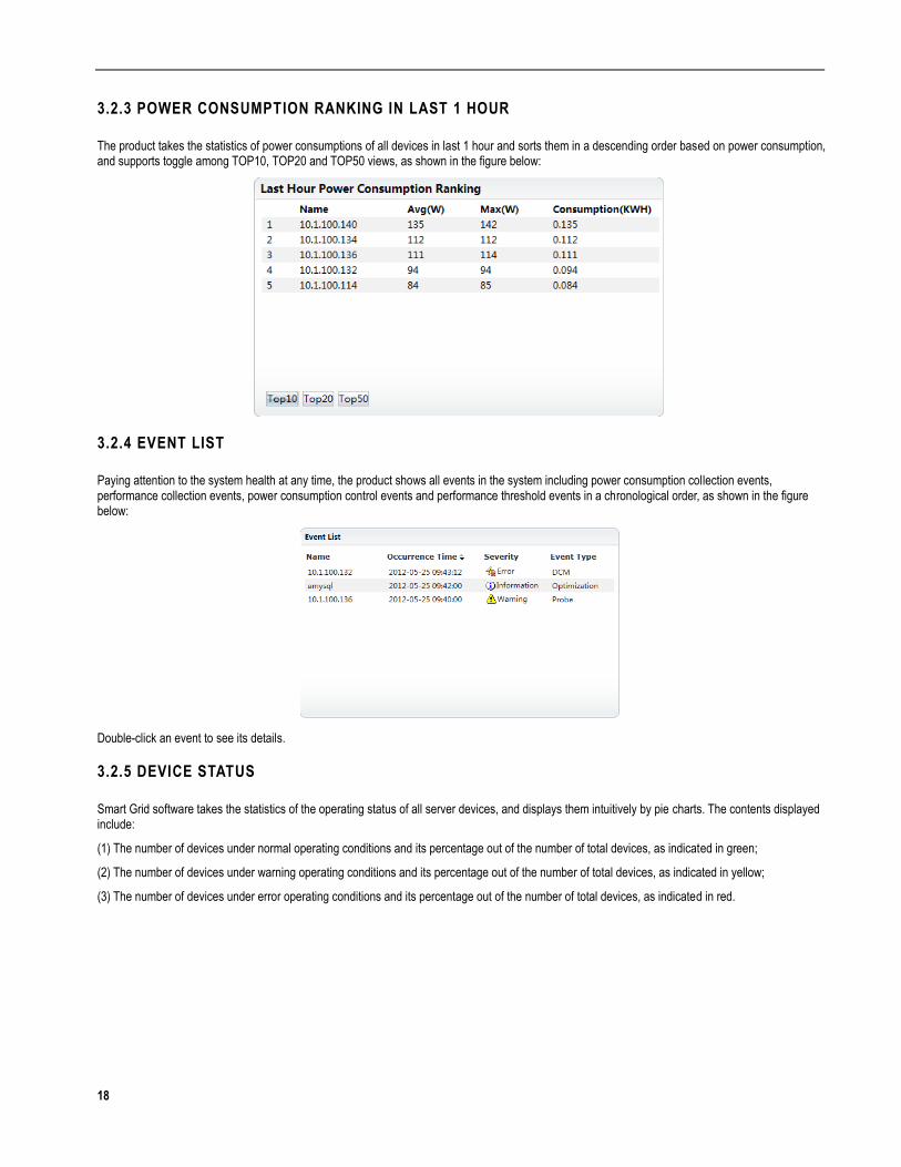
3.2.3 POWER CONSUMPTION RANKING IN LAST 1 HOUR
The product takes the statistics of power consumptions of all devices in last 1 hour and sorts them in a descending order based on power consumption, and supports toggle among TOP10, TOP20 and TOP50 views, as shown in the figure below:
3.2.4 EVENT LIST
Paying attention to the system health at any time, the product shows all events in the system including power consumption collection events, performance collection events, power consumption control events and performance threshold events in a chronological order, as shown in the figure below:
Double-click an event to see its details.
3.2.5 DEVICE STATUS
Smart Grid software takes the statistics of the operating status of all server devices, and displays them intuitively by pie charts. The contents displayed include:
(1) The number of devices under normal operating conditions and its percentage out of the number of total devices, as indicated in green;
(2) The number of devices under warning operating conditions and its percentage out of the number of total devices, as indicated in yellow;
(3) The number of devices under error operating conditions and its percentage out of the number of total devices, as indicated in red.

19
3.3 SYSTEM CONFIGURATION
3.3.1 ACTIVATE SOFTWARE
Smart Grid is a paid software, and you can have free trial for 90 days to manage 50 server nodes without entering the authorization serial number. After expiration, you can purchase the serial number of the product through Lenovo website, Lenovo customer service number or other channels. You can continue to use this software after entering the product serial number into the system.
At present, the software provides two types of product serial numbers based on the amount of manageable server nodes by providing product serial numbers for 5 nodes or 50 nodes separately. This software use the number of the BMC IP addresses of server devices stored in the software to take the statistics of usage of the authorization serial number. One BMC IP address is corresponding to one authorized node.
Operation Steps: from System Login System Management License.
In the License screen, the number of server nodes in which the current system supports management, the number of managed server nodes and the number of server nodes which are still manageable are displayed.
If the software is activated for the first time, the "Free Trial" message on the top of the system interface will automatically disappear after the successful activation.
Lenovo Website: http://support.lenovo.com
Lenovo customer service number: 880-810-8888
3.3.2 GLOBAL CONFIGURATION
Perform the global parameter configuration of the system for Smart Grid, including:
Electricity Price: The electricity cost per kWh used for calculating the total electricity bill. Configuring the actual electricity price of machine room (unit price per kilowatt-hour), which is used to estimate the total power charge with the software.
Performance Store Time: Configure the store time of original performance data. The system provides up to 120 days of storage, default 30 days.
Event Store Time: Configure the store time of all the collected events. The system provides up to 120 days of storage, default 30 days.
Operation Steps: from System Login System Management Global Configuration
3.3.3 USER MANAGEMENT
If you want to assign users to your team to share this product with you, you only need to add appropriate user information.
Operation steps: from System Login System Management User Management, click "Add" to complete the addition of a new user. The required information includes: user name, password and password confirmation.
User types include administrator and general user:
Administrator: Can perform any actions without any restriction.
General User: Only has the permission to view the managed devices, but unable to perform any actions to them.
3.4 DEVICE DISCOVERY
20
3.4.1 AUTO DISCOVERY
When you run Smart Grid for the first time, the devices will be discovered automatically in the use wizard. If the network changes subsequently (for example, addition of a new device), you can trigger auto discovery of devices in the system manually.
Operation steps: from System Login Home, click the "Device Discovery" button or from System Login Device management Device List, click the "Auto Discovery" button.
Set necessary parameters for IPMI collection to discover new devices, including:
The BMC address range that needs to be discovered;
Subnet mask;
The BMC user name and password.
3.4.2 BATCH IMPORT
You can add the devices which are temporarily disconnected or the planned new devices to the system by batch import. When the access is provided subsequently, you can manage the devices.
Before importing, you are required to fill in the information related to your device according to the requirements in the Resource Import template.
You may directly get access to the resource import template from the system. Please refer to the description of "Export" functions in Section 3.5.5 Import/Export.
Operation Steps: from System Login Device Management Device List, click the "Import" button to select prepared device listing, and then the operation of batch import for devices will be completed.
3.4.3 ADD A SINGLE DEVICE
The system supports to add a single device manually.
Operation Steps: from System Login Device Management Device List, click the "Add" button to complete the device information to finish the addition of a single device, and pay attention to the following points during completion:
Device Information: fill in the basic properties of the device, and the fields with are required. Device name is used as an unique identification of an device, thus cannot be duplicated; at the same time, BMC IP address is also used as an unique identification and cannot be duplicated.
Due to the fact that all the newly added device are at the learning stage, the learning cycle needs to be configured.
Basic Information: fill in the basic device information such as manufacturer, model, application type, and etc., among which the application types include normal application, web service and database, specifically speaking web service refers to servers mainly providing webpage access service, database refers to servers mainly providing database service, and other service types are categorized as normal application.
Collection configuration: if it's required to monitor the CPU usage or memory usage of the server devices, then it's required to configure the information necessary for data collection, including the information such as operating system type, access account and password. For the account information for accessing the operating system, you can use either the Administrator account or general user accounts. From the standpoint of access security, it is recommended to use a dedicated user account for data collection.

21
3.5 DEVICE MANAGEMENT
3.5.1 DEVICE INFORMATION LOOKUP
The system supports three ways of viewing device information: device list, device group, device tree diagram.
Operation Steps: from System Login Device Management Device List/Device Tree Diagram/Device Group, the form and the included information are presented.
1. Device List
Under the device list, the devices can be searched and filtered through the criteria such as device name, IP address, device group, operating system and device status. The system includes no criteria by default, but displays the information of all server devices.
Under the server device list, the basic information of every server will be displayed in the list, including connectivity status, name, device group, IP address, BMC address, rated power (W), empirical power (W), operating system and device information status. Where:
Connectivity status: it indicates whether the operating system IP address of the managed server can be accessed through ping protocol; if access is established, the green icon will be shown, otherwise the system will determine that the managed device is inaccessible, and the gray icon will be shown. The response to Ping the managed server device from the Smart Grid server.
Device name: the unique name for the system of server device;
Device group: the name of the device group which the server device belongs to;
IP address: the IP address of the operating system on the server;
BMC address: the BMC IP address for the server device;
Rated power: the rated output power of the server device power and its value is usually marked on the nameplate of the server device.
Empirical power: the power value required by server device for normal operation and its value is usually lower than the rated power of the server device.
Operating system: the type of operating system on the server, such as Windows or Linux.
Device status: the server status of the current server device, such as Learning Stage, Enable Policy, Policy Enabled, In Exception Status and etc.
Through clicking the header of the server device list, the server device property values can be sorted in the ascending/descending order and they are sorted in ascending order by device name by default.
The user interface of the device list, as illustrated below:

22
2. Device Tree Diagram
Through the device tree diagram, the server devices can be organized into a tree-shape management structure with clear management. Depending on the management needs, different management models can be employed, such as:
(1) Organize according to the physical space model which is "Machine Room --> Floor --> Room --> Rack Row --> Rack --> Server Devices" and organize by device group including devices or sub device group.
(2) Organize according to the model of device manufacture which is "Device Manufacture --> Server Device".
In Smart Grid, the system has built two default groups "Lenovo" and "UnGrouped" that cannot be deleted. They are designed to automatically add all ThinkServer severs found by device auto discovery into the "Lenovo" device group, and to add all non-ThinkServer servers into the "UnGrouped" device group.
When Smart Grid exercises the power consumption control on the device group, Smart Grid will allocate the available power based on the priority of the devices in the device group. Under the equivalent conditions, the devices that have higher priority will receive more power than the devices that have lower priority.
Through the device tree diagram, adding, editing and deleting server devices as well as setting the group that a device belongs to and setting the priority of a server device can be achieved.
The user interface of the device tree diagram, as illustrated below:
3. Device Groups
In the screen device groups, adding, editing and deleting a device group as well as changing the status of a device group can be achieved.

23
Click Group Name to drill down to view the device list of each device group, as shown in the figure below:
3.5.2 STATUS MANAGEMENT
Device status includes Manual Maintenance and System Modification.
The device management status of manual maintenance includes: Learning Stage, Policy Enabled, Policy Forbidden and Unmanaged. This allows delicate device management.
Leaning Stage: The device is at data initializing collection stage, preparing for loading appropriate policy. Through the observation on this stage, the user can better understand the rule of power consumption of a server device.
Policy Enabled: The device is automatically set to "Enable Policy" status after learning stage. You can select corresponding policy as required. On the basis of the power consumption during the learning status, the user can configure the best power consumption policy according to the rule of power consumption. Smart Grid provides a variety of convenient settings approaches, please refer to the description in Section 3.7 Power Consumption Control for details.
Policy Forbidden: confirm the devices that will not enable any power consumption policy, but will collect the power consumption and performance data of the device.
Unmanaged: The device is not manageable by the system after being automatically discovered. Such devices neither collect power consumption nor manage performance.
The status of system modification includes In Exception and Policy Enabled.
In Exception: The device status will be automatically set to In Exception by the system when power consumption of the device can't be collected. The abnormal device can't be applied power consumption policy until it can normally collect power consumption.
Policy Enabled: The device status will be automatically set to Policy Enabled by the system when the power consumption control policy is enabled, indicating that the device has added energy-saving policy.
1. The Conversion Process under Normal Device Status
Under normal circumstances, for power consumption control on server devices or device groups, it's required to toggle in the conversion process under normal device status, i.e. to follow the process of "Device Discovery --> Learning Stage --> Enable Policy --> Policy Enabled". According to the load changes during the server operation, the data collected from the original learning stage has not been able to accurately reflect the trend of power consumption, at this moment one may reenter to the "Learning Stage" by changing the status from "Policy Enabled" or "Enable Policy" to conduct power consumption data monitoring.

24
2. The Conversion Process under Policy Forbidden
During the operation of a server device, it's clearly required to only perform power consumption monitoring on the server device, but not conduct power consumption control. Server devices enter into the Policy Forbidden status, then can normally collect power consumption and performance data (if proceeded with performance collection configuration). Policy Forbidden status can be entered from Learning Stage status, Enable Policy status and Policy Enabled status. It is possible to convert from the Policy Forbidden status to Learning Stage status. The Conversion Process under Policy Forbidden, as shown in the figure below:
3. The Conversion Process under the In Exception Status
During the operating of the server device, the situation that the power consumption data cannot be collected may happen, in event of such situation, the device will automatically enter the In Exception Status until the power consumption data can be collected, then the device will recover from the In Exception Status to the previous status. For example: the situation that the power consumption data cannot be collected happens during the Learning Stage, the sever will enter into In Exception Status, and when the power consumption data can be collected normally, then the server will recover from In Exception status to Learning Stage status. The Conversion Process under In Exception Status, as shown in the figure below:
25
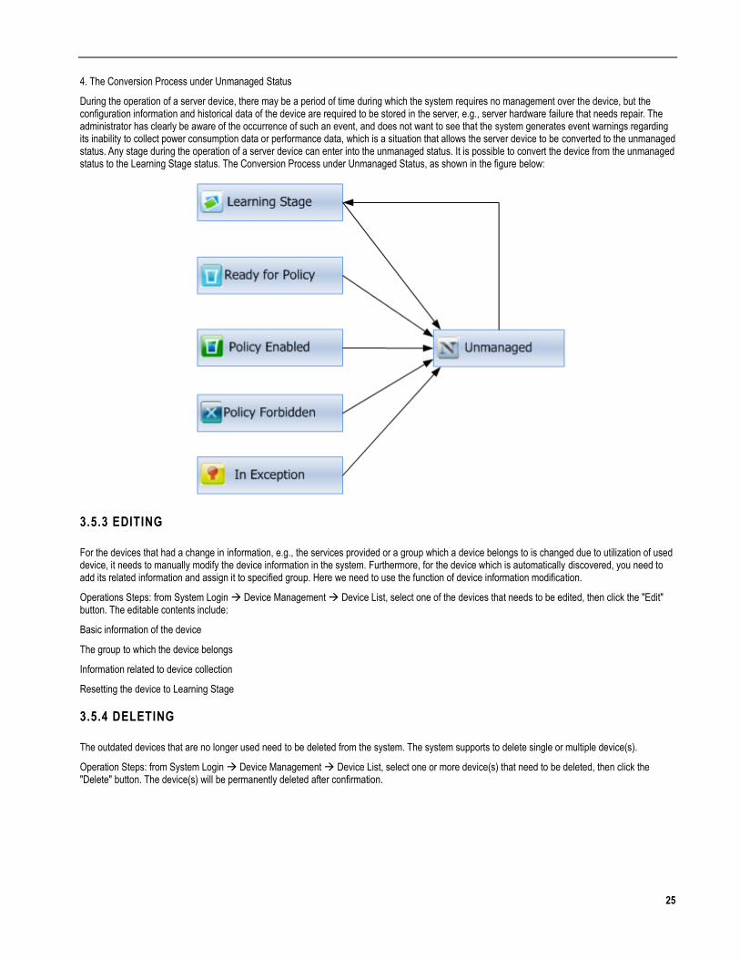
4. The Conversion Process under Unmanaged Status
During the operation of a server device, there may be a period of time during which the system requires no management over the device, but the configuration information and historical data of the device are required to be stored in the server, e.g., server hardware failure that needs repair. The administrator has clearly be aware of the occurrence of such an event, and does not want to see that the system generates event warnings regarding its inability to collect power consumption data or performance data, which is a situation that allows the server device to be converted to the unmanaged status. Any stage during the operation of a server device can enter into the unmanaged status. It is possible to convert the device from the unmanaged status to the Learning Stage status. The Conversion Process under Unmanaged Status, as shown in the figure below:
3.5.3 EDITING
For the devices that had a change in information, e.g., the services provided or a group which a device belongs to is changed due to utilization of used device, it needs to manually modify the device information in the system. Furthermore, for the device which is automatically discovered, you need to add its related information and assign it to specified group. Here we need to use the function of device information modification.
Operations Steps: from System Login Device Management Device List, select one of the devices that needs to be edited, then click the "Edit" button. The editable contents include:
Basic information of the device
The group to which the device belongs
Information related to device collection
Resetting the device to Learning Stage
3.5.4 DELETING
The outdated devices that are no longer used need to be deleted from the system. The system supports to delete single or multiple device(s).
Operation Steps: from System Login Device Management Device List, select one or more device(s) that need to be deleted, then click the "Delete" button. The device(s) will be permanently deleted after confirmation.

26
3.5.5 IMPORT/EXPORT
In the event of machine room reallocation or server reallocation which can affect a large number of the current connected devices, or when Smart Grid network needs to be adjusted or Smart Grid needs to be temporarily uninstalled, it is recommended to use the export function to backup the devices that have been managed, and use the import function to resume the service end of Smart Grid upon the recovery of the system.
The system supports the function of exporting the queried device list into excel.
This excel can be directly imported into the system.
After the list was re-imported, the device will be automatically recovered to the management status before it was exported.
For the instruction of the import function, please refer to the description in 3.4.2 Batch Import.
Operation Steps: from System Login Device Management Device List, click the "Export" button to export the currently retrieved listing results. If no query term is selected, all the results will be exported by default. The exported list can be directly used as the import template for batch import of devices.
3.5.6 POWER CONSUMPTION MANAGEMENT
After selecting a single device, click the "Power Consumption Management" button to view the power consumption information of the device.
3.5.7 PERFORMANCE MANAGEMENT
After selecting a single device, click the "Performance Management" to view the performance information of the device.
3.6 POWER CONSUMPTION MONITORING AND LEARNING
You may use the power consumption monitoring function to monitor the power consumption of the device in real time, and monitor the power consumption characteristics of each device, preparing for the subsequent policy enabling.
3.6.1 POWER CONSUMPTION MONITORING
All the devices (groups) with power consumption collection capability have independent virtual electric meter (i.e. soft electric meter), which can display the power consumption data within a cycle switching, including power consumption, peak power and saved power, by switching statistic cycles. The related power consumption data will be automatically collected and refreshed every minute. You can find out the trends of power consumption by viewing the power consumption curve.
Power Consumption (kWh): Display the total sum of the power consumption within the statistic cycle.
Peak Power (kW): Display the maximum power to which the device can reach in one minute within the statistic cycle.
Saved Power: Display the total sum of saved power within the statistic cycle.
Operation Steps: from System Login Power Consumption Management Power Consumption Monitoring, select a device (group) that needs to be monitored from the tree diagram to get the information related to the power consumption of the device (group).
For all the devices, you can:
Switch the object that you want to monitor by selecting the device (group) in the device tree diagram.
Display power consumption, peak power consumption and saved power of the device in real time.
Display the recent power consumption changes of the device through curve diagram and support the switch of time granularities.
Display the basic resource information of the device.
For the device to which a policy is applied, you can:
Display the threshold line of energy saving policy directly in the trend chart.
Manually modify and switch the policy loaded by the device.
Add new energy saving policies.
27
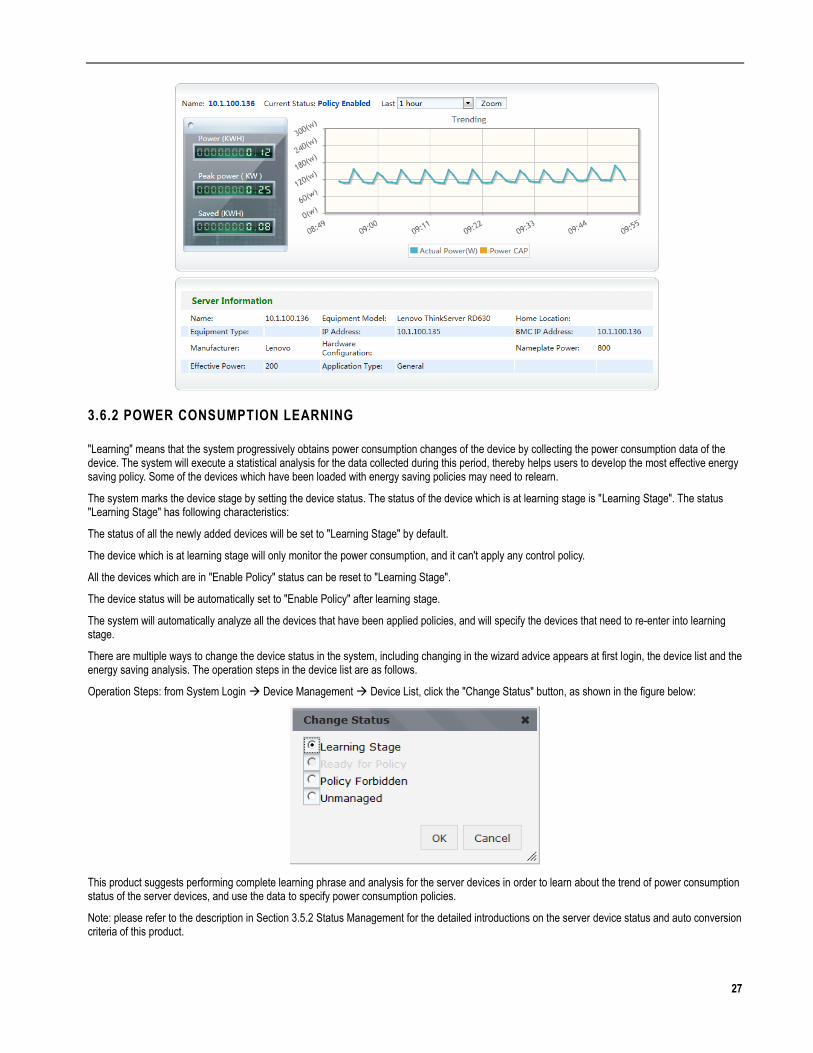
3.6.2 POWER CONSUMPTION LEARNING
"Learning" means that the system progressively obtains power consumption changes of the device by collecting the power consumption data of the device. The system will execute a statistical analysis for the data collected during this period, thereby helps users to develop the most effective energy saving policy. Some of the devices which have been loaded with energy saving policies may need to relearn.
The system marks the device stage by setting the device status. The status of the device which is at learning stage is "Learning Stage". The status "Learning Stage" has following characteristics:
The status of all the newly added devices will be set to "Learning Stage" by default.
The device which is at learning stage will only monitor the power consumption, and it can't apply any control policy.
All the devices which are in "Enable Policy" status can be reset to "Learning Stage".
The device status will be automatically set to "Enable Policy" after learning stage.
The system will automatically analyze all the devices that have been applied policies, and will specify the devices that need to re-enter into learning stage.
There are multiple ways to change the device status in the system, including changing in the wizard advice appears at first login, the device list and the energy saving analysis. The operation steps in the device list are as follows.
Operation Steps: from System Login Device Management Device List, click the "Change Status" button, as shown in the figure below:
This product suggests performing complete learning phrase and analysis for the server devices in order to learn about the trend of power consumption status of the server devices, and use the data to specify power consumption policies.
Note: please refer to the description in Section 3.5.2 Status Management for the detailed introductions on the server device status and auto conversion criteria of this product.
28
3.7 POWER CONSUMPTION CONTROL
The devices can apply energy saving policy when their status are automatically set to "Enable Policy" after completing learning stage, or when you manually set the status to "Enable Policy", otherwise, the policy related interface will not appear.
Energy Saving Policy refers to the control policy which is used to reduce power consumption. You can use the policy pre-defined by the system or create a new policy to apply it to the device (group), achieving the goal of power consumption control and energy saving.
This product saves the information power consumption control policy into the hardware of the servers by communication with the server devices. When a server device is added/deleted from the server device, all power consumption control policies stored in the hardware of the server will be deleted. Before the physical removal of the managed server device, it is recommended to clear the hardware of the server device that stores the information of power consumption control policies; this can be accomplished through the product by deleting or disabling all energy saving policies on the server device and enabling all energy saving policy on the group which the device belongs to.
3.7.1 MANAGEMENT POLICY
1. Default Policy
According to the characteristics of resource consumption in different applications, the system provides five types of default policies that can be used for power consumption control of the device for the first; 5%, 10%, 15% energy saving, workday power consumption control policy and holiday power consumption control policy. For each different application type, different default policies can be enabled, and subsequently create new energy saving policy based on the actual energy saving status.
The application server that is mainly used for CPU calculation (e.g. Web server). Such application has higher CPU performance requirements and may save less energy. We recommend to apply 5% of energy saving policy.
The application server that is mainly used for memory application, such application has lower CPU performance requirements than that of the first kind of server. We recommend to apply 10% of energy saving policy.
The application server that is mainly used for disk I/O (e.g. database server), such application has the lowest CPU performance requirements, therefore may save the most energy. We recommend to apply 15% of energy saving policy.
Workday power consumption control policy: power consumption control policy effective during the workdays from Monday through Friday with the default energy saving goal of 10%. For the servers that mainly receive higher traffic over the weekend, and less traffic during the weekdays, it is recommended to enable weekday energy saving policy.
Holiday power consumption control policy: power consumption control policy effective at Saturday and Sunday with the default energy saving goal of 10% For the servers that mainly receive higher traffic over the weekdays, and less traffic during the weekends, it is recommended to enable weekend energy saving policy.
2. Adding a New Policy
A policy can be applied to a device or a device group. Where: A device can share the policies of its device group, however, the device policies under different groups can't be shared. Select the planned type that you need to add and fill in the related parameters to complete the addition of policy.
3. Priority of Policy
You can select the corresponding priority for each policy:
The energy saving policies that conflict with one another will be loaded by priority. Policies with higher priority will be loaded first.
For the policies that conflict with one another but have the same priority, the policy that has smaller energy saving control value will be loaded first.
4. Editing/Deleting a Policy
Select a policy to perform modification and deletion action.
5. Enabling/Disabling a Policy
Select a required policy, click the "Enable" button to apply the corresponding policy to the device (group).
Select a required policy, click the "Disable" button to remove the corresponding policy from the device (group).
If the device group has already activated a policy, all policies of all devices themselves within the group will be deactivated. The system will adjust the power consumption control policy of the device group based on the energy saving policy of the device group.

29
To control the power consumption through the method of enabling policy, only the device (group) with "Enable Policy" status can be configured with power consumption policy, as shown in the figure below:
Display "Currently Effective Policy: Holiday" in the interface, and show all the policies that can be loaded.
3.7.2 POLICY DESCRIPTION
1. Custom Policy
The power consumption management function that you can use to set corresponding power consumption control value according to the power consumption distribution rule of the device at different time points. The system provides power consumption management function of time dimension (the granularity is 1 hour), you can set different power capping value according to occupied/available periods of the device. After enabling such policy, the power consumption value of the device or device group during a corresponding period of time will be controlled below the power capping. You can set the floating ratio of the baseline according to the data accumulated during learning stage, or set the power consumption control value at each time point in hours.
2. Database Policy
If the managed device has database related application, it is recommended to use database energy saving plan. This energy saving policy is customized according to database scenario. The device will dynamically adjust power consumption according to the performance of database application after policy configuration, therefore achieves maximum energy saving without affecting the service. For example, if the execution time of a SQL in database is about 20 ms, it indicates that the database performance is normal, so the threshold of the response time can be set to 18 ms. If the execution time of a SQL is less than 18 ms, the power consumption control will be performed and it will stop when the execution time is close to 18 ms.
When enabling this policy, all other policies which are being enabled will be disabled.
30
Parameter Descriptions:
SQL Execution Time: Set the response time threshold of a SQL according to the SQL that separately configured for each device in the device information. If the response time is below the threshold, the power consumption of the device will be gradually reduced, until the optimum power consumption value is found and fixed; meanwhile, once the actual performance value is close to or over the threshold, the system will stop to perform power consumption control.
Energy Saving Ratio: The maximum ratio of the required energy saving. When achieves this goal, the system will stop to further reduce power consumption and keep the power consumption control at this ratio regardless of the service performance.
Note:
SQL execution time should reflect the performance changes of the database in a correct and clear way.
The selected SQL must be safe enough and the SQL with potential security risk must not be used. It is recommended to create database user specially for Smart Grid in DB and to access specific database table, so that the user database safety will be unaffected.
It is recommended to limit the ratio of database energy saving to about 20%.
To enable the power consumption management of the database server, you need to correctly configure collection information related to the database server, for example, JDBC, SQL etc.
Web Service Policy
If the managed device applications include Web server, it is recommended to use Web server energy saving plan. This energy saving plan is customized according to Web server scenario. The device will dynamically adjust power consumption according to the performance of Web server application after plan configuration, therefore achieves maximum energy saving without affecting the service. For example, if the page can be opened within 2-5 ms after being clicked by the user, and it has no impact upon user perception, then the threshold can be set to 4 ms. If the response time is less than 4 ms, the power consumption control will be performed and it will stop when the execution time is close to 4 ms.
When enabling this policy, all other policies which are being enabled will be disabled.
Parameter Descriptions:
HTTP Response Time: Set the HTTP response time threshold according to the URL that separately configured for each device in the device information. If the response time is below the threshold, the power consumption of the device will be gradually reduced, until the optimum power consumption value is found and fixed; meanwhile, once the actual performance value is close to or over the threshold, the system will stop to perform power consumption control.
Energy Saving Ratio: The maximum ratio of the required energy saving, when reaching this target, the system will stop further perform power consumption control regardless of the service performance.
Note:
It is recommended to limit the set response time to 3-5 ms.
Since Web service is more sensitive to device performance, the ratio of energy saving should not be set too large and it is recommended to set it around 5%-10%.
Filling in a URL can best reflect the Web service performance and the address which is not related to the service, and therefore the normal service running will not be affected.
3.7.3 POLICY OPERATING STATUS
Through comparing the power consumption during the learning phrase with current power consumption, whether enabled policy is appropriate can be determined, and the device(s) needing adjustment will be listed to remind users to adjust the policy. Meanwhile, for the device(s) needing adjustment, the user can directly select the device on the webpage by clicking the "Go Back to the Learning Phrase", and put it to the learning phrase again; the analysis includes:
The power consumption of all the devices in learning stage, current power consumption and saved power.
Screen out the device that probably needs to be adjusted, primarily the device that fail to achieve energy saving effect, through system analysis.
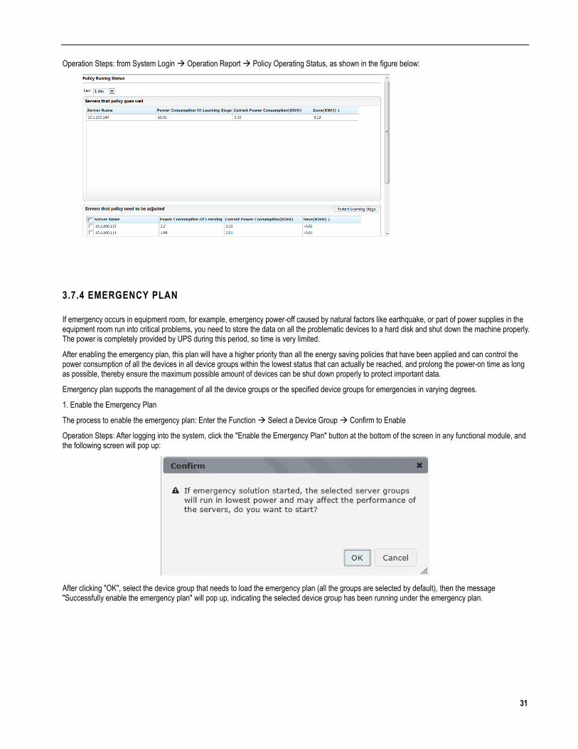
31
Operation Steps: from System Login Operation Report Policy Operating Status, as shown in the figure below:
3.7.4 EMERGENCY PLAN
If emergency occurs in equipment room, for example, emergency power-off caused by natural factors like earthquake, or part of power supplies in the equipment room run into critical problems, you need to store the data on all the problematic devices to a hard disk and shut down the machine properly. The power is completely provided by UPS during this period, so time is very limited.
After enabling the emergency plan, this plan will have a higher priority than all the energy saving policies that have been applied and can control the power consumption of all the devices in all device groups within the lowest status that can actually be reached, and prolong the power-on time as long as possible, thereby ensure the maximum possible amount of devices can be shut down properly to protect important data.
Emergency plan supports the management of all the device groups or the specified device groups for emergencies in varying degrees.
1. Enable the Emergency Plan
The process to enable the emergency plan: Enter the Function Select a Device Group Confirm to Enable
Operation Steps: After logging into the system, click the "Enable the Emergency Plan" button at the bottom of the screen in any functional module, and the following screen will pop up:
After clicking "OK", select the device group that needs to load the emergency plan (all the groups are selected by default), then the message "Successfully enable the emergency plan" will pop up, indicating the selected device group has been running under the emergency plan.

32
2. Stop the Emergency Plan
To Stop the emergency plan is to restore all the devices at emergency status into normal status.
Operation Steps: After logging into the system, click the "Stop the Emergency Plan" at the bottom of the screen in any functional module, and the following screen will pop up:
Select the device group that needs to be stopped, and after clicking the "OK" button, the message "Successfully disable the emergency plan!" will pop up, and the device group will restore to normal operating status.
3.8 PERFORMANCE MANAGEMENT
Through real-time performance monitoring, you can learn about the running conditions of the devices that have applied policies, and timely discover performance risks due to power consumption control.
3.8.1 PERFORMANCE MONITORING
You can monitor the running condition of a single device by monitoring the critical performance data, thereby discover the running trouble of the device and the hidden danger. Moreover, power consumption control will affect the device performance, so you need to avoid affecting service by monitoring the device performance in real time, setting performance threshold alarm and by timely discovering the decreasing of device performance. Performance data will be collected and refreshed every 5 minutes.
Operation Steps: from System Login Performance Management Performance Monitoring, select the device that needs to be viewed in the tree diagram to get the critical real-time performance of the device.
You can select the device in the device tree diagram to switch the object that needs to be monitored.
Real-time CPU usage and historical trends.
Real-time memory usage and historical trends.
View all the events related to the selected device.
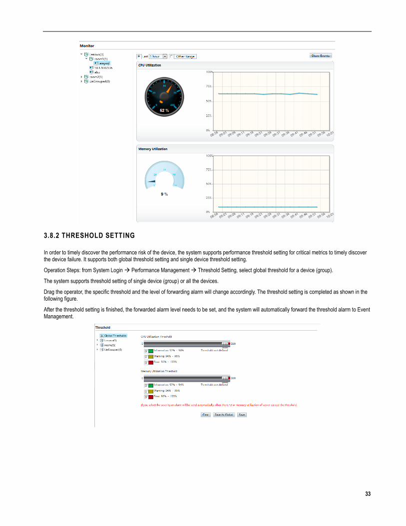
33
3.8.2 THRESHOLD SETTING
In order to timely discover the performance risk of the device, the system supports performance threshold setting for critical metrics to timely discover the device failure. It supports both global threshold setting and single device threshold setting.
Operation Steps: from System Login Performance Management Threshold Setting, select global threshold for a device (group).
The system supports threshold setting of single device (group) or all the devices.
Drag the operator, the specific threshold and the level of forwarding alarm will change accordingly. The threshold setting is completed as shown in the following figure.
After the threshold setting is finished, the forwarded alarm level needs to be set, and the system will automatically forward the threshold alarm to Event Management.
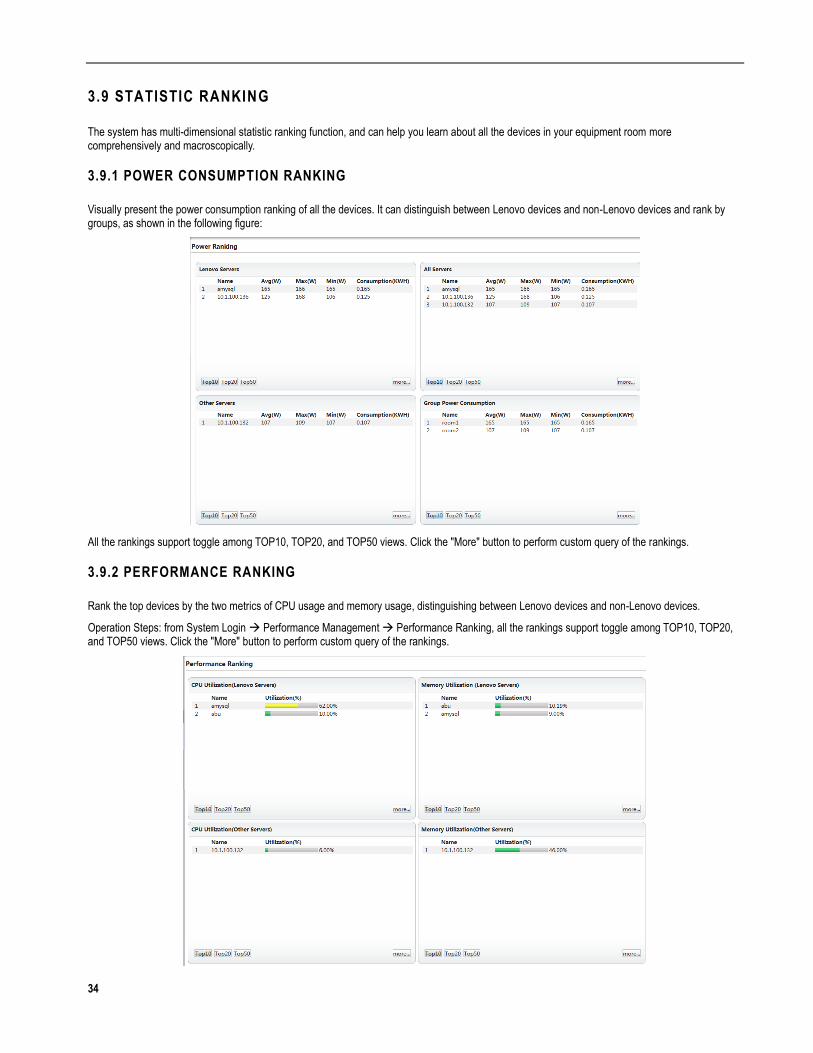
34
3.9 STATISTIC RANKING
The system has multi-dimensional statistic ranking function, and can help you learn about all the devices in your equipment room more comprehensively and macroscopically.
3.9.1 POWER CONSUMPTION RANKING
Visually present the power consumption ranking of all the devices. It can distinguish between Lenovo devices and non-Lenovo devices and rank by groups, as shown in the following figure:
All the rankings support toggle among TOP10, TOP20, and TOP50 views. Click the "More" button to perform custom query of the rankings.
3.9.2 PERFORMANCE RANKING
Rank the top devices by the two metrics of CPU usage and memory usage, distinguishing between Lenovo devices and non-Lenovo devices.
Operation Steps: from System Login Performance Management Performance Ranking, all the rankings support toggle among TOP10, TOP20, and TOP50 views. Click the "More" button to perform custom query of the rankings.

35
3.10 OPERATION REPORT
3.10.1 REPORT FUNCTIONS
The system provides multi-dimensional operating reports. The functions supported by the report are as follows:
Select the date that needs to be queried.
Depending on the various granularities of the reports, supports the fast switch among Today, Yesterday, The Day Before Yesterday, The Last 7 Days, The Last 30 Days, This Week, Last Week, This Month, Last Month.
The report contains trend chart and detailed data.
All the reports support export function.
3.10.2 REPORT EXPLAINED
1. Power consumption per hour (day)
View the power consumption of the device (group) in a day by hour granularity, as shown in the following figure.
Click the "Power Consumption Comparison" button to view comparison between the current day with the previous day or comparison between any two days, as shown in the figure below:
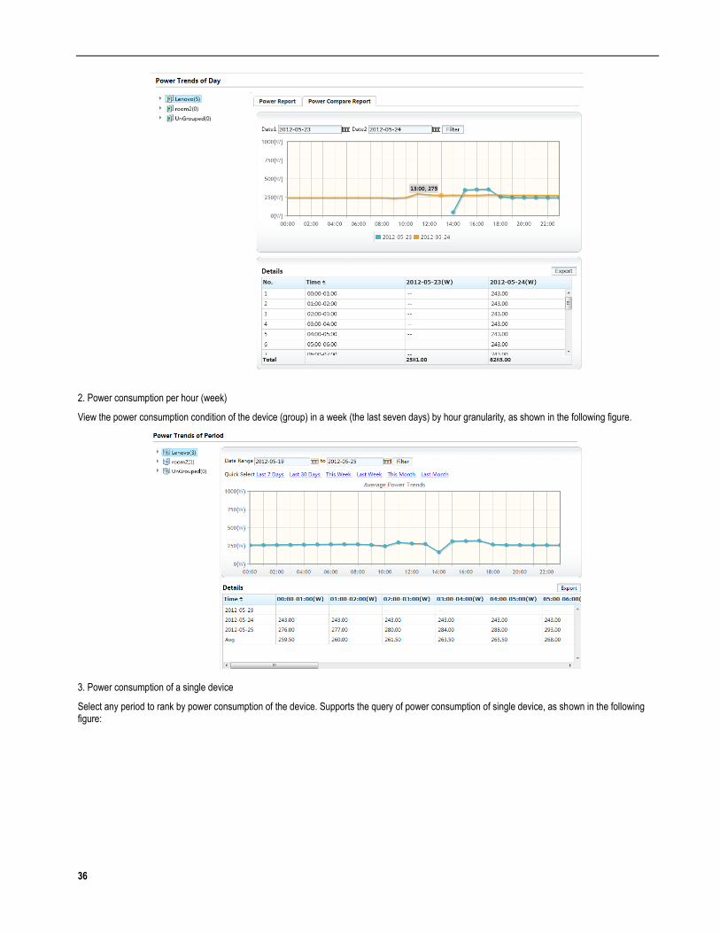
36
2. Power consumption per hour (week)
View the power consumption condition of the device (group) in a week (the last seven days) by hour granularity, as shown in the following figure.
3. Power consumption of a single device
Select any period to rank by power consumption of the device. Supports the query of power consumption of single device, as shown in the following figure:
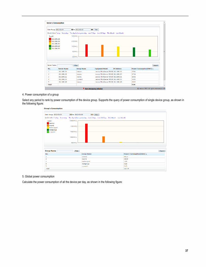
37
4. Power consumption of a group
Select any period to rank by power consumption of the device group. Supports the query of power consumption of single device group, as shown in the following figure:
5. Global power consumption
Calculate the power consumption of all the device per day, as shown in the following figure:

38
3.11 EVENT MANAGEMENT
Besides the monitoring staff actively monitors the running condition of the device, you can also view various events that happen to all the devices through centralized event management. After configuring the forwarding, the related personnel will be immediately informed about the failure for handling.
3.11.1 EVENT LIST
A flow window that presents events in a unified way. It can display the latest events in real time.
Operation Steps: from System Login Event Management Event List
The presented events include:
DCM Event: the information of some abnormal situations occur when the system acquires the power consumption of a device and the information of event cleanup after recovery from abnormal situations.
Dynamic policy events: the information that system controls the power consumption of the devices.
Collector events: the information of abnormal situations occur when the system acquires the server performance and the information of event cleanup after recovery from abnormal situations, e.g. errors in user name and password of a device, and etc.
Threshold events: performance threshold warning events due to set threshold and the information of event cleanup.
Includes the following functions:
To search events by event name, event type, start and end time and level.
For repeated event, its occurrence number will be automatically accumulated and merged into one event.
Double-click a single event, or select an event and click the "Details" button to view the details of the event.
Some significant events need to be forwarded to related person in charge to reminder them to pay attention to them or deal with them. The system supports manual forwarding of the events to the person concerned. To manually forward an event or several events, click the "Forward" button and configure the recipient(s) concerned, then the selected event(s) can be forwarded via email manually.
Delete one or more selected event(s).
3.11.2 FORWARDING CONFIGURATION
Maintainers need to be immediately informed of serious failures. The system supports the function of automatic forwarding of events with specific type and level. After selecting the event type, alarm level, and configuring the related information of message forwarding, the corresponding event system will immediately forward the information to the configured person after the system receiving it.
Operation Steps: from System Login Event Management Forwarding Configuration, the configured parameters include:

39
Select the type of the event that needs to be automatically forwarded.
Select the alarm level that needs to be automatically forwarded.
Fill in the correct information related to mail gateway, for example, gateway address, user name, password etc.
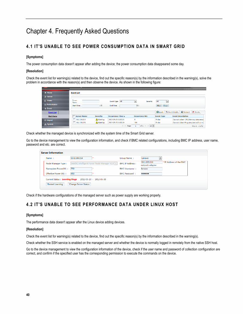
40
Chapter 4. Frequently Asked Questions
4.1 IT 'S UNABLE TO SEE POWER CONSUMPTION DATA IN SMART GRID
[Symptoms]
The power consumption data doesn't appear after adding the device; the power consumption data disappeared some day.
[Resolution]
Check the event list for warning(s) related to the device, find out the specific reason(s) by the information described in the warning(s), solve the problem in accordance with the reason(s) and then observe the device. As shown in the following figure:
Check whether the managed device is synchronized with the system time of the Smart Grid server.
Go to the device management to view the configuration information, and check if BMC related configurations, including BMC IP address, user name, password and etc. are correct.
Check if the hardware configurations of the managed server such as power supply are working properly.
4.2 IT 'S UNABLE TO SEE PERFORMANCE DATA UNDER LINUX HOST
[Symptoms]
The performance data doesn't appear after the Linux device adding devices.
[Resolution]
Check the event list for warning(s) related to the device, find out the specific reason(s) by the information described in the warning(s).
Check whether the SSH service is enabled on the managed server and whether the device is normally logged in remotely from the native SSH host.
Go to the device management to view the configuration information of the device, check if the user name and password of collection configuration are correct, and confirm if the specified user has the corresponding permission to execute the commands on the device.
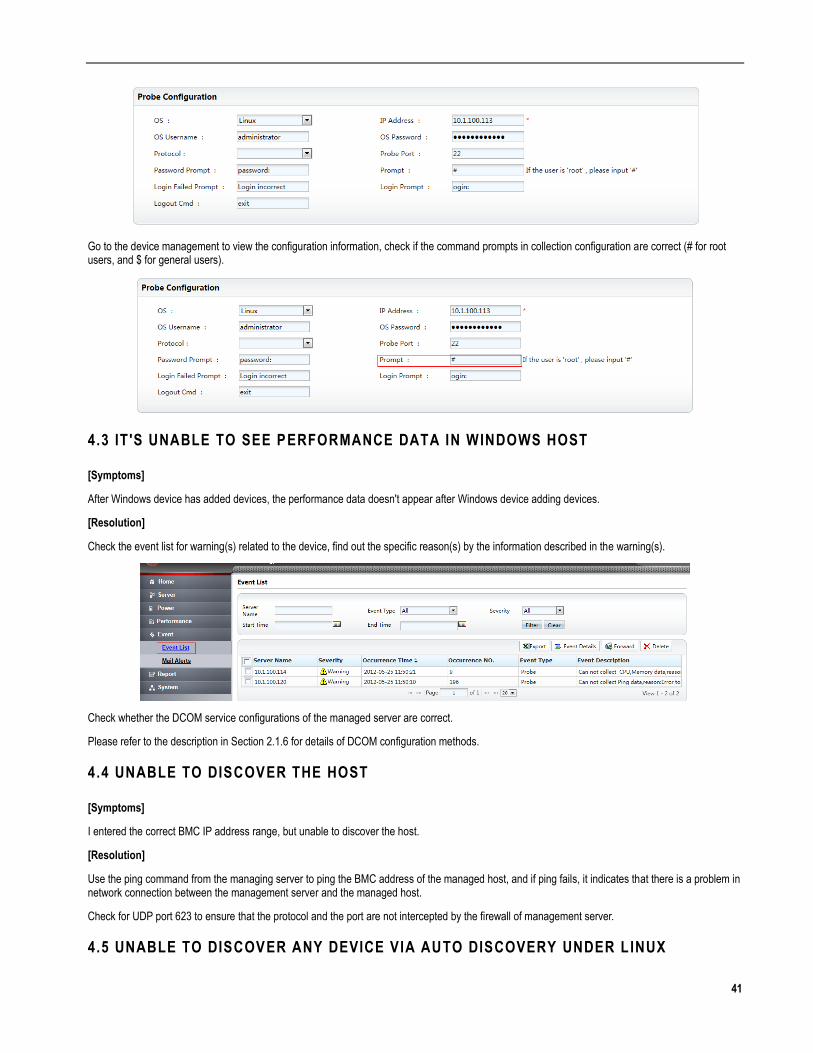
41
Go to the device management to view the configuration information, check if the command prompts in collection configuration are correct (# for root users, and $ for general users).
4.3 IT 'S UNABLE TO SEE PERFORMANCE DATA IN WINDOWS HOST
[Symptoms]
After Windows device has added devices, the performance data doesn't appear after Windows device adding devices.
[Resolution]
Check the event list for warning(s) related to the device, find out the specific reason(s) by the information described in the warning(s).
Check whether the DCOM service configurations of the managed server are correct.
Please refer to the description in Section 2.1.6 for details of DCOM configuration methods.
4.4 UNABLE TO DISCOVER THE HOST
[Symptoms]
I entered the correct BMC IP address range, but unable to discover the host.
[Resolution]
Use the ping command from the managing server to ping the BMC address of the managed host, and if ping fails, it indicates that there is a problem in network connection between the management server and the managed host.
Check for UDP port 623 to ensure that the protocol and the port are not intercepted by the firewall of management server.
4.5 UNABLE TO DISCOVER ANY DEVICE VIA AUTO DISCOVERY UNDER L INUX
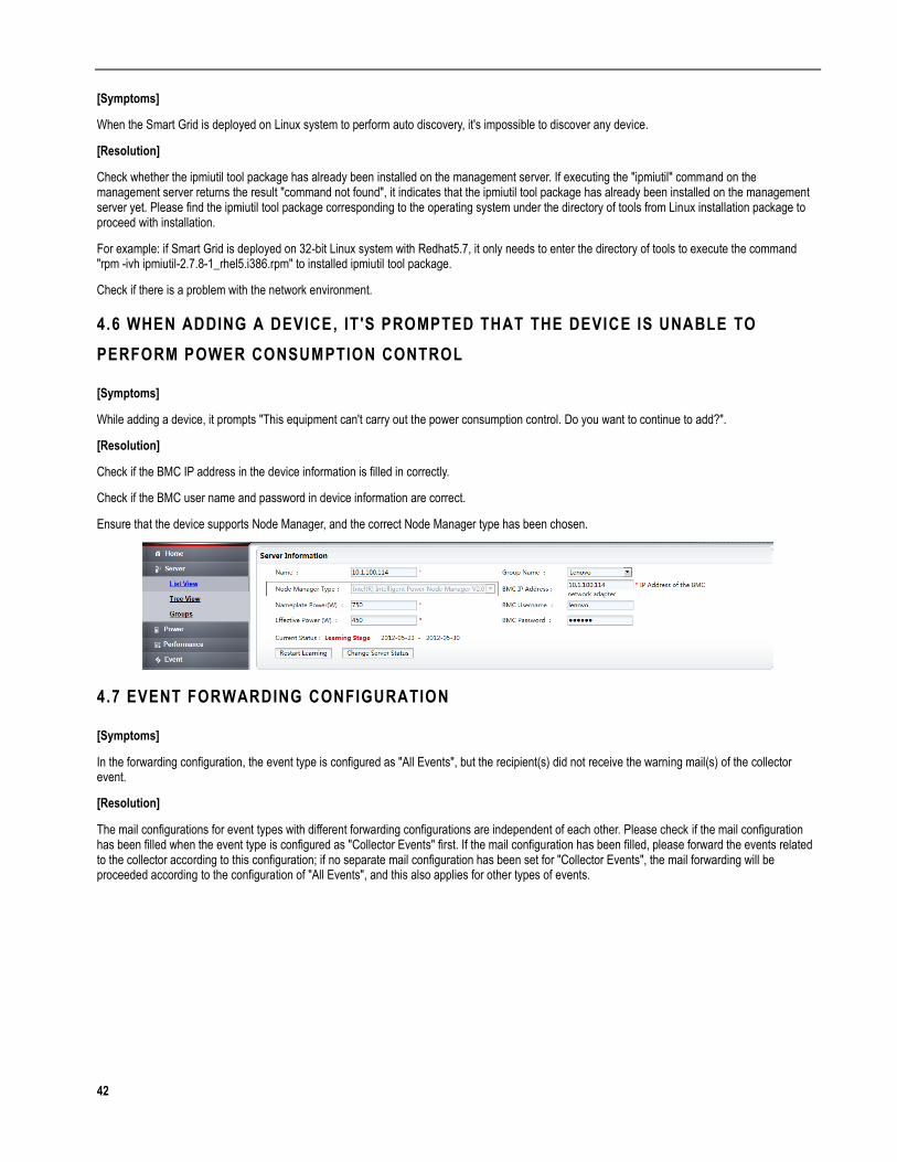
42
[Symptoms]
When the Smart Grid is deployed on Linux system to perform auto discovery, it's impossible to discover any device.
[Resolution]
Check whether the ipmiutil tool package has already been installed on the management server. If executing the "ipmiutil" command on the management server returns the result "command not found", it indicates that the ipmiutil tool package has already been installed on the management server yet. Please find the ipmiutil tool package corresponding to the operating system under the directory of tools from Linux installation package to proceed with installation.
For example: if Smart Grid is deployed on 32-bit Linux system with Redhat5.7, it only needs to enter the directory of tools to execute the command "rpm -ivh ipmiutil-2.7.8-1_rhel5.i386.rpm" to installed ipmiutil tool package.
Check if there is a problem with the network environment.
4.6 WHEN ADDING A DEVICE, IT 'S PROMPTED THAT THE DEVICE IS UNABLE TO
PERFORM POWER CONSUMPTION CONTROL
[Symptoms]
While adding a device, it prompts "This equipment can't carry out the power consumption control. Do you want to continue to add?".
[Resolution]
Check if the BMC IP address in the device information is filled in correctly.
Check if the BMC user name and password in device information are correct.
Ensure that the device supports Node Manager, and the correct Node Manager type has been chosen.
4.7 EVENT FORWARDING CONFIGURATION
[Symptoms]
In the forwarding configuration, the event type is configured as "All Events", but the recipient(s) did not receive the warning mail(s) of the collector event.
[Resolution]
The mail configurations for event types with different forwarding configurations are independent of each other. Please check if the mail configuration has been filled when the event type is configured as "Collector Events" first. If the mail configuration has been filled, please forward the events related to the collector according to this configuration; if no separate mail configuration has been set for "Collector Events", the mail forwarding will be proceeded according to the configuration of "All Events", and this also applies for other types of events.
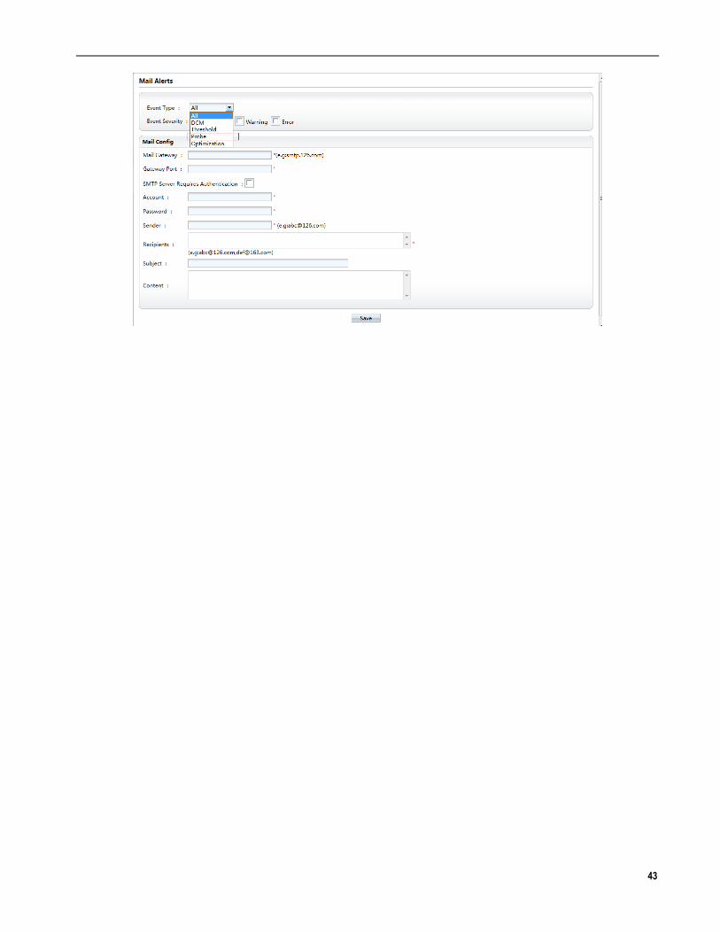
43

44
Appendix 1: Glossary and Abbreviations
DCM
Intel(R) Data Center Manager, a software development kit to provide basic services such as monitoring and management of power consumption for the servers, racks, and server groups in the data center.
IPMI
Intelligent Platform Management Interface, an open standard hardware management interface specification, which defines the particular protocol for communication with embedded management subsystem.
BMC
Baseboard Management Controller, the industrial standard IPMI protocol which provide IPMI interface externally.
DMZ
Demilitarized Zone, a buffer zone created between the a non-secure system and a secure system, in order to solve the problem that the external network cannot get access to the internal network after the installation of the firewall.
Node Manager
Intelligent Node Management, a power management technology embedded in the Intel server chipset, including v1.5 and v2.0 versions.
NTP
Network Time Protocol, a protocol for synchronizing the times of different computers, can synchronize computers to their server or other clock sources (e.g., quartz clock, GPS, and etc.), providing a high-accurate time correction (discrepancies with standard time less that 1 millisecond in a LAN, and tens of milliseconds in a WAN), and can prevent from attacks by malicious protocols in the way of confirmation with encryption.
Smart Grid server
A server used for installing the server terminal software of ThinkServer Smart Grid Technology.
Rated Power
The rated output power of the server device power and its value is usually marked on the nameplate of the server device.
Empirical Power
The power value required by server device for normal operation and its value is usually lower than the rated power of the server device
Power Saved
The difference between the power consumption of all managed server devices running under empirical power and the power consumption of all server devices under actual running.
Virtual Electricity Meter
As opposed to the actual electricity meter, the virtual electricity meter for devices provided by Smart Grid can show real-time power consumption in the software graphically.

45
Appendix 2: Smart Grid Event Type Description
Level Event Type Event Description
Errors DCM Event DCM lost communication with a node
Information DCM Event DCM restored communication with a node
Alarms Collector event Can not collect CPU utilization ratio and Memory utilization ratio, reason: The server refuses to connect. Please be sure that the Telnet/SSH service on the server is configured correctly.
Alarms Collector event Can not collect probe data, reason: Operating system type not set for probe
Alarms Collector event Can not collect Ping data, reason: Error to connect to the server
Alarms Collector event Can not collect CPU utilization ratio and Memory utilization ratio, reason: DCOM error.
Alarms Collector event Can not collect CPU utilization ratio and Memory utilization ratio, reason: Message not found for errorCode:
Alarms Dynamic policy event Can not collect CPU utilization ratio to optimize power consumption
Alarms Dynamic policy event Cannot set dynamic policy, the KPI of service is bad, CPU utilization ratio is normal
Alarms Dynamic policy event Can not remove policy from DCM
Information/Alarms/Errors Threshold event Memory utilization ratio > X%
Information/Alarms/Errors Threshold event CPU utilization ratio > X%
Note: “X” is a threshold value, which is configured via Threshold Setting page.