thesis work 030424final2 - diva portalhv.diva-portal.org/smash/get/diva2:215409/fulltext01.pdf ·...
TRANSCRIPT

2003:M011
THESIS WORK
Alternative Dynamic Impact Testing Component Screening of FMH-Energy Absorber Safety Plastic™
David Bourne H99mk
April 24, 2003
University of Trollhättan/Uddevalla Department of Technology
Box 957, S-461 29 Trollhättan, SWEDEN Phone: +46 520 47 50 00 Fax: +46 520 47 50 99
E-mail: [email protected]
i
THESIS WORK
Alternative Dynamic Impact Testing Component Screening of FMH-Energy Absorber Safety Plastic™
Summary This Thesis project, 10 out of a total 120 credits, represents the concluding assignment in a Bachelor of Science degree in Mechanical Engineering given by the University of Trollhättan/Uddevalla. The project took place at the department of Interior Safety Validation, Saab Automobile AB in Trollhättan.
All passenger cars marketed and sold in North America are required to comply with the upper interior head-impact legislation, FMVSS 201U. This federal law was designed to improve occupant safety by reducing injuries to the head and neck caused by head impacts with hard structures of the vehicles upper interior. Compliance with legislation involves rigorous in-vehicle component testing performed by impacting a Free Motion Headform (FMH) onto specified target points and zones.
In-vehicle FMH-testing incorporates many variables i.e. body-in white, interior trim components, energy absorber, test apparatus etc. The largely undefined test environment caused by these numerous variables both complicate and limit effective research and development solutions. The objective of thesis work was to develop and evaluate a new method of dynamic screening, based upon the same grounds as the FMH-testing carried out today but without the added complication of the vehicle and its many unknown variables.
After initial trials and modifications, the newly developed prototype Fixed Flight Pneumatic (FFP) impacter seemed well tuned and verified for the purpose of Safety Plastic component screening. Impact tests were conducted and data examined with a focus on velocity vs. HIC(d) and acceleration peak.
Results from screening tests carried out on the Safety Plastic absorber SP-B152 show evidence of an alarming variation in energy absorption characteristics, and begin to clarify the reason or reasons behind the relative large span of HIC(d) values attained from earlier in-vehicle testing.
FFP-impact testing is relatively inexpensive and quick to perform. The steel impacter and target-beam allow for a reliable and repetitive dynamic test procedure preserving certain key elements of traditional FMH-testing and at the same time reducing the number of unknown factors and therefore creating a more conclusive method of screening.
Keywords: Energy absorbers. FMVSS 201U. FMH, Free Motion Head. Dynamic Impact Testing. Fixed Flight Pneumatic (FFP) impacter.
Publisher: University of Trollhättan/Uddevalla, Department of Technology Box 957, S-461 29 Trollhättan, SWEDEN Phone: + 46 520 47 50 00 Fax: + 46 520 47 50 99 E-mail: [email protected]
Author: David Bourne Examiner: Lector Mats Eriksson University Tutor: Kjell Hurtig Advisor: Henrik Kahra, Saab Automobile AB Subject: Mechanical Engineering, Product Development Language: English Number: 2003:M011 Date: April 24, 2003
Alternative Dynamic Impact Testing
ii
Preface This report describes the findings of a Thesis project on the subject of Alternative Dynamic Impact Testing, and represents the concluding assignment in a Bachelor of Science degree in Mechanical Engineering given by the University of Trollhättan/Uddevalla.
The project took place at the department of Interior Safety Validation, Saab Automobile AB in Trollhättan and sought to evaluate a new concept of component screening using the newly developed prototype Fixed Flight Pneumatic (FFP) impacter and target-beam assembly. The main objective of the project being to find a viable alternative test method to the costly FMH (Free Motion Head) in-vehicle testing and/or the rather limited quasi-static test method used for component screening today.
The prototype FFP-impacter together with its target-beam assembly has in my opinion proved itself as a valuable tool. The prototypes main objective to enable testing in a well-defined environment has been achieved. I believe that there are worthy grounds for further studies, and that a continuation will inevitably aid in a greater understanding of the energy absorption process and further the development of energy absorbers and vehicle design.
It is my hope that you as the reader find this report interesting and that it may be of genuine help to development engineers working in the field of FMH impact testing and/or manufacturers of energy absorbers.
Trollhättan 24 April, 2003
David Bourne

Alternative Dynamic Impact Testing
iii
Contents Summary ...........................................................................................................................i Preface ............................................................................................................................. ii Contents.......................................................................................................................... iii 1 Introduction.................................................................................................................1
1.1 Background and Problem Description ..................................................................1 1.2 Purpose ..................................................................................................................2 1.3 Scope......................................................................................................................2
2 Legal Requirement .....................................................................................................3 2.1 Design - FMH Performance Requirements ...........................................................3 2.2 FMH Impact Testing..............................................................................................4 2.3 Alternative Dynamic Impact Testing .....................................................................4
3 Test Equipment and Instrumentation ......................................................................5 3.1 Fixed Flight Pneumatic (FFP) Impacter Assembly...............................................5 3.2 Target-beam Assembly...........................................................................................7
4 Initial Trials and Validation ......................................................................................8 4.1 Fixed Flight Pneumatic Impacter..........................................................................8 4.2 Initial Screening Trials: Energy absorber SP-B152 ............................................8
5 Component Screening - Safety Plastic™ ..................................................................9 5.1 Safety Plastic™ Component SP-B152...................................................................9
5.1.1 Production Process Control – Static Energy Absorption Criteria .............9 5.2 FFP-Test Procedure ............................................................................................10
5.2.1 Component Pre-Test Preparation.............................................................10 5.2.2 Test Equipment … Pre-Test Adjustments and Settings...........................10 5.2.3 Post-Test Data Processing .......................................................................11
5.3 Test Results and Analysis ....................................................................................11 5.4 Quasi-static Testing vs. Dynamic Testing ...........................................................12
6 Recommendations.....................................................................................................13 7 Conclusions................................................................................................................13 8 Acknowledgements ...................................................................................................13 9 References..................................................................................................................14 Appendices .....................................................................................................................15

Alternative Dynamic Impact Testing
1
1 Introduction This Thesis project, 10 out of a total 120 credits, represents the concluding assignment in a Bachelor of Science degree in Mechanical Engineering given by the University of Trollhättan/Uddevalla. The project, planned to continue a period of 10 weeks, took place at the department Interior Safety Validation, Saab Automobile AB in Trollhättan. This report is intended for engineers and personnel at the department of Interior Safety Validation at Saab, engineers and personnel working for The Oakwood Group, and other mechanical engineers to whom it may interest.
1.1 Background and Problem Description
All passenger cars marketed and sold in North America are required to comply with the upper interior head-impact legislation, FMVSS 201U. This federal law was designed to improve occupant safety by reducing injuries to the head and neck caused by head impacts with hard structures of the vehicles upper interior. Compliance with legislation involves rigorous in-vehicle component testing performed by impacting a Free Motion Headform (FMH) onto specified target points and zones at any speed up to and including 24 km/h. Legislation states a maximum Head Injury Criteria (HIC) of 1000HIC(d) (see chapter 2.2 FMH Impact Testing), this figure being calculated from the deceleration rate of the free motion headform on impacting the vehicles interior.
Much of the work completed at Saab’s Interior Safety Validation lab has been concentrated to vehicle compliance through in-vehicle testing. And although FMH-test results answer the question as to whether or not the vehicle complies with relevant legislation, i.e. 1000 HIC(d), they give very little explanation as to the reason or reasons behind specific values and/or in certain cases to the noticeable statistical deviation, when comparing impact results.
In order to increase both FMH-test consistency and reliability there must be a closer study of the many individual parameters that can contribute to a test result. There are many variables i.e. body-in white (BIW), interior trim components, energy absorber, test apparatus etc, all of which may add to complicate effective interpretation of test results. Clearly in-vehicle testing has its limitations and as a consequence effective research and development solutions become both difficult to identify and assess.
In cooperation with engineers at Saab a new prototype test rig was constructed and built. One of the main objectives behind this work aimed to develop a new method of dynamic testing based on the same grounds as the FMH-testing carried out today but without the added complication of in-vehicle testing. By excluding the vehicle, engineers hope to drastically reduce the number of unknown variables and in doing so, create a well-defined and repetitive test environment.

Alternative Dynamic Impact Testing
2
This thesis project is an attempt to isolate and study one of these variables, carrying out a component screening of the energy absorber Safety Plastic™ - Basell 152 (SP-B152), using the prototype FFP-impacter, to generate test data.
1.2 Purpose
Purposes of this thesis project:
• To assemble the prototype FFP-impacter and target-beam assembly, run trials and validate the test rig for operational functionality.
• To validate a new method of testing appropriate for the component screening of energy absorber SP-B152.
• To perform dynamic energy screening on the energy absorber SP-B152.
• Evaluate and compare variations in results between Static energy screening vs. dynamic energy screening.
1.3 Scope
The scope of this thesis project is limited to:
• Initial test rig trials aim only to validate operational functionality.
• Initial operational trials are limited to contain a minimum of 10 and a maximum of 40 impact tests.
• Component screening is limited to a series of maximum 3 x 30 parts = 90 impacts.
• Component screening is isolated to identifying variation in the material SP-B152’s energy absorbing characteristics.

Alternative Dynamic Impact Testing
3
2 Legal Requirement
During crashes and rollovers, impacts with hard structures in car interiors account for nearly 60 000 occupant head injuries annually. Of these, 4,070 injuries are severe (Abbreviated Injury Scale, AIS of 3 or greater) and 2,430 are fatal, making these impacts the leading cause of fatal head injuries in crashes. Analysis of 1988 to 1992 accident data shows the percentage of head injuries is approximately the same for both restrained and unrestrained occupants.
(Sounik 1997, s.1) [1]
In 1995 the American National Highway Traffic Safety Administration (NHTSA) introduced new legislation requiring all passenger cars, trucks, buses and multipurpose vehicles with a gross vehicle rating of 10 000lbs (4 536 kilograms) or less to provide head impact protection. The Federal Motor Vehicle Safety Standard, FMVSS 201U Upper Interior Head Impact Protection, defines the test procedure requirements necessary for compliance with this standard. [2]
The required test procedure for compliance to FMVSS 201U stipulates a crash simulation using a Hybrid III Headform and maximum impact criteria of 1000HIC(d). A more detailed description of HIC(d) value and FMH impact testing is given in chapter 2.2 FMH Impact Testing of this report.
2.1 Design - FMH Performance Requirements The introduction of the FMVSS 201U standard has had a major influence on the subsequent interior design and engineering of the upper interior trim components. Pillar trim, headliners, door panels etc. are no longer parts, used mainly to aesthetically cover underlying steel structures, but have an inbuilt function to successfully manage head impact energy in the event of collision, and therefore greatly reducing occupant injury. One of the key solutions in successfully meeting with legislation is the use of energy managing materials integrated into component design or alternatively placed between interior covering and bodywork.
Some designs will incorporate a cartridge of energy absorbing ribs while others adopt the use of a variety of energy absorbing polyurethane foams or aluminium honeycomb. More recently the material, Safety Plastic™, a propylene polymer sheet of cones, has been successfully introduced on the market.

Alternative Dynamic Impact Testing
4
2.2 FMH Impact Testing FMVSS 201U standard requires manufacturers to certify a vehicle using a featureless, modified Hybrid III Free Motion Headform to simulate a crash situation.
FMH component testing requires the headform to be launched and impacted against the vehicles upper interior surface at a velocity of 24 km/h (15mph), using specific target zones and approach angles. The 4.54 kg (10 lbs.) headform is equipped with three piezoresistive accelerometers arranged in a three dimensional orthogonal coordinate system, and allow acceleration over time to be measured during testing. The collected data is then used to compute the headform launch, impact sequence, and corresponding head injury criteria, HIC(d), which shall not exceed 1000.
When analysing crash simulations using a full crash test dummy, impact data is computed to calculate a HIC value. FMH-testing uses a dummy head equivalent, HIC(d) – this represents the test value that would have been achieved had a full crash test dummy been used.
Head Injury Criteria
(Full crash test dummy)
Equation (1) A = resultant FMH acceleration (g’s)
T1, T2 = any two points in time during impact which maximise HIC
Head Injury Criteria (d)
(Featureless dummy head)
Equation (2) HIC(d) = 0,75448(HIC) + 166,4
2.3 Alternative Dynamic Impact Testing In-vehicle FMH-testing is a lengthy and very costly method, and as stated earlier involves so many variables that the test environment is anything but repetitive. Even when great care is taken to systematise the test procedure it is impossible to say as to whether all the materials, the mounting/fitting, and test equipment are consistent with earlier tests. Tolerances in the body-in white, interior trim components, and test apparatus all contribute to the comparative span in results.
Alternative Dynamic Impact Testing
5
In order to study individual aspects of an impact test, it is essential to reduce the number of variables to a minimum. With this in mind a new prototype dynamic test rig was constructed. Engineers at Saab had earlier carried out research using dynamic impact testing; a study of energy absorbing materials using a drop tower test rig, component testing using a “Fast Path” linear impact machine and a pendulum test rig, are examples. But in designing the new apparatus more focus was made on emulating an FMH-test.
3 Test Equipment and Instrumentation
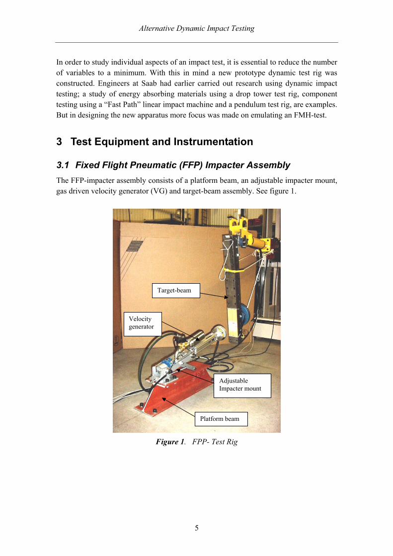
3.1 Fixed Flight Pneumatic (FFP) Impacter Assembly The FFP-impacter assembly consists of a platform beam, an adjustable impacter mount, gas driven velocity generator (VG) and target-beam assembly. See figure 1.
Figure 1. FPP- Test Rig
Velocity generator
Platform beam
Adjustable Impacter mount
Target-beam

Alternative Dynamic Impact Testing
6
Key design features of this assembly are:
• The impacter assembly is constructed to be robust, compact and rigidly secured to the workshop floor – this in order to minimise/eliminate impacter movement during the launching sequence.
• The gas-driven velocity generator is essentially the same as those used in in-vehicle testing, although lengthened and utilizing modified exhaust ports in order to simulate a free flight sequence.
• The impacter mount allows a vertical adjustment through a positive angle of 0° to 50°. (Typical FMH target approach angles span from -10° to +50°. Note, in order to simplify the construction of this early prototype test rig, no negative angle adjustment has been made possible).
• The impacter assembly, i.e. pneumatic piston, shaft and 135 mm dia. flat steel plate impacter is adjusted to a weight of 4.54 kg (= free motion headform).
The above design factors allow dynamic impact testing primarily under the same conditions as with in-vehicle testing, but without the problem of impacter recoil movement and without the complications associated with both FMH-testing using a dummy headform and other additional variations from BIW, trim components, etc.
Figure 2. Fixed Flight Pneumatic Impacter Assembly
The FFP-impacter assembly is also equipped with a force transducer (Interface model no. 1210-AF-IK, range ± 4.5 kN) integrated as a part of the impacter mount, and providing force measurements in the X-direction during impact testing. This information was primarily sought after to increase the general understanding of the forces the impacter assembly is exposed to during test.
Modified exhaust port
Steel Impacter Plate
Adjustable Impacter Mount

Alternative Dynamic Impact Testing
7
3.2 Target-beam Assembly The Target-beam assembly consists of a vertically suspended 105 cm long “Milo”-beam supported by a 25 mm axle, bearing housings and mounting brackets. A standard MGA Research Corporation FMH-rig is used to support/hang the assembly allowing both lateral and vertical adjustment. See figure 3.
A thin steel plate (100 mm x 280 mm x 2 mm) glued on to the beam and centrally positioned 800 mm from the fulcrum point, performs as a target area backing plate. The beam’s backside is equipped with a boss allowing weights to be easily attached at a chosen height. The choice of a freely hung supported beam combined with a diverse amount of additional weight allows the target-beam assembly a certain amount of adjustment. Additional weight permits a change in and the beam’s moment of inertia and therefore the possibility to vary how rigid a target the beam will represent. Test fixture design represents a “worst case scenario” for head impact i.e. rigid body but at the same time allows a restricted amount of travel in order to simulate in-vehicle body-in white movement during impact.
Figure 3. Target-beam Assembly
25mm axle and bearing housing
Additional attached weights

Alternative Dynamic Impact Testing
8
Two piezoresistive accelerometers (Endevco model no. 7264B, 2000 T maximum) are mounted on the beams backside providing acceleration measurements in the X-direction (i.e. tangential beam acceleration) and Y-direction (i.e. centripetal beam acceleration) of travel, thus enabling the impact swing travel to be computed.
4 Initial Trials and Validation
4.1 Fixed Flight Pneumatic Impacter After initial assembly and securing, trial runs were made to verify operational functionality, i.e. that the assembly proved to be of sound and rigid construction permitting adequate acceleration and thrust free impacting at speeds up to 24 km/h. Modifications were made to the velocity generator’s cylinder, which in comparison with a standard model was lengthened and machined to have longer exhaust ports. The standard square-profiled shaft was exchanged for a longer cylindrical-profiled shaft. These modifications worked well making possible both good acceleration and the necessary thrust-free impact sequence.
4.2 Initial Screening Trials: Energy absorber SP-B152 The primary tests to be completed on the Safety Plastic™ absorber SP-B152, used an aluminium 6,5 inch dia. hemisphere (FMVSS 201 and J-921head form) impact head shape. This proved to be appropriate when testing cellular plastics but inadequate when testing Safety Plastic™ due to the absorbers sparse cone structure. The impacter shape was later changed to a 135 mm dia. flat steel plate – this arrangement proved to be more suitable for this application. In order to retain FMH characteristics the plate was adjusted to weigh a total 4.54 kg (= free motion headform) when assembled together with its shaft and piston. Although this method of screening differs from tests using a dummy headform, impacts with the same velocity will nonetheless contain equal amounts of impact energy.
The target-beam was tested together with various amounts of weight attached. After analysis and comparison of the various resulting dynamic force vs. displacement data, a scenario with 10 kg positioned 0.72 m from the fulcrum point was decided upon – in this way the beam presented sufficient resistance allowing the SP-B152 absorber to be effectively crushed before initiating movement. The beam was also equipped with a leash, which restrained it from collision with the impacter plate on its return swing.
After these various adjustments the FFP-impacter and target-beam seemed well tuned and verified for the purpose of Safety Plastic™ screening. Test data showed that when key variables such as impact speed, target precision, etc. were kept the same, consistent test results were achieved.

Alternative Dynamic Impact Testing
9
5 Component Screening - Safety Plastic™
5.1 Safety Plastic™ Component SP-B152 The component SP-B152 a Safety Plastic™ product, manufacture by The Oakwood Group, is a plastic sheet thermo formed to cones with a height of 15 mm, made from the propylene polymer - Basell SV152 and with a base sheet thickness of 0.03 inches (approx. 0.76 mm). Products made from Safety Plastic™ are designed to efficiently collapse, buckling under mechanical stress, and as a consequence able to absorb energy.
5.1.1 Production Process Control – Static Energy Absorption Criteria
During the process of manufacturing component samples are regularly appraised using quasi-static compression testing with a flat plate indenter. This destructive form of testing provides a measurement of the static energy absorbed. The static value is plotted in a control chart and compared to a nominal static energy criterion. The component supplier has also stipulated an upper and lower limit indicating acceptable parts, while parts outside of this range are to be rejected.
One of the questions that this thesis work will try to answer is whether or not this static method of screening is appropriate. In-vehicle FMH impact testing with this component has shown a worrying statistical spread of results. A dynamic method of screening may indicate whether or not a static energy absorption criterion is a suitable unit of quality control. And if so are the upper and lower limits of this screening method relevant to the levels of quality sought after in FMH testing.
To aid this investigation the manufacturer has kindly donated component samples especially produced for this purpose. A total of 90 component parts were delivered – 30 parts formed near the centre of static energy criteria, 30 parts formed at the low of the criteria, and 30 formed on the high end of the criteria. See appendix 2.

Alternative Dynamic Impact Testing
10
5.2 FFP-Test Procedure
5.2.1 Component Pre-Test Preparation
All of the original SP-B152 components were cut down to size in order to fit the dimensions of both impacter and target-beam. The remaining test item had 17 cones and an effective area of approx 91cm2. See figure 4.
Figure 4. Safety Plastic™ SP-B152 Test Item
Each part and remnant were marked with a serial number: Low static energy = SPl # … Good static energy = SPg #… High static energy = SPh #…
5.2.2 Test Equipment … Pre-Test Adjustments and Settings
All component tests present in this report were performed with a vertical impacter angle of 10 degrees. The target-beam was hung, restrained with a leash at a corresponding perpendicular angle to the direction of impact. Prior to each impact, the distance between absorber and impacter plate was controlled to be 170 mm within a tolerance of approx 1 mm.
The absorber was marked with a centreline and attached to the beam’s target plate, using a conventional 0,2 mm thick double-sided tape, and positioned on a correspond-ing centreline 800 mm from the beam’s fulcrum point.
All tests were carried out in ambient air conditions (FMVSS 201U specified).
SP-B152 cut to size
Alternative Dynamic Impact Testing
11
5.2.3 Post-Test Data Processing
A Kayser-Threde digital data acquisition system with a data sampling rate of 20,000 Hz (12 bit) and the software program WinCarat II v 4.50 were utilised to collect impact data output signals. These were later computed using the measurement and analysis program DIAdem™ 8.1 – Saab Automobile AB.
Analysis and measurement of each impact gave the values for, velocity prior to impact (at a distance =165 mm), Head Impact Criteria HIC(d), and maximum acceleration peak. A complete documentation over each component test and the corresponding impact data was recorded in an Excel data sheet.
Post-test component material was removed, visually inspected and stored for future reference.
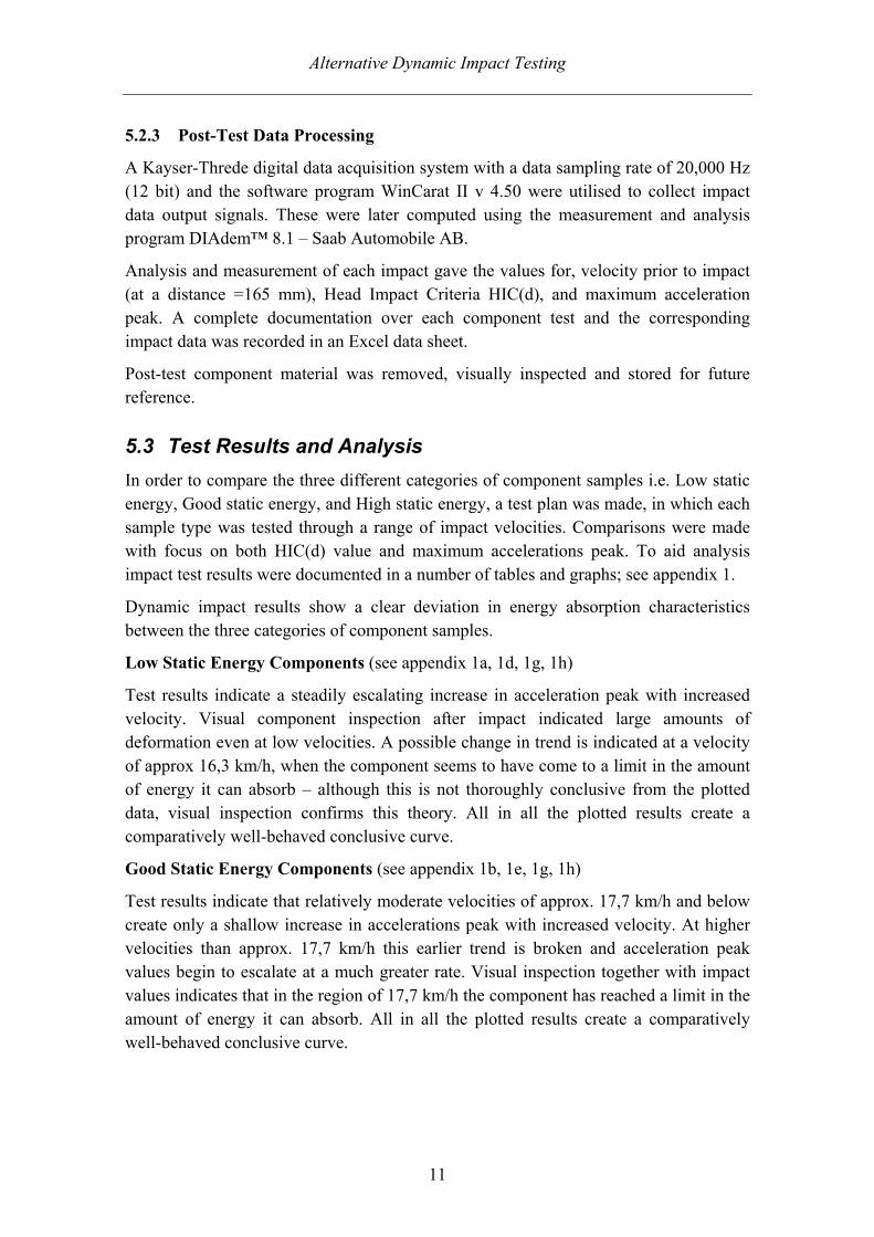
5.3 Test Results and Analysis In order to compare the three different categories of component samples i.e. Low static energy, Good static energy, and High static energy, a test plan was made, in which each sample type was tested through a range of impact velocities. Comparisons were made with focus on both HIC(d) value and maximum accelerations peak. To aid analysis impact test results were documented in a number of tables and graphs; see appendix 1.
Dynamic impact results show a clear deviation in energy absorption characteristics between the three categories of component samples.
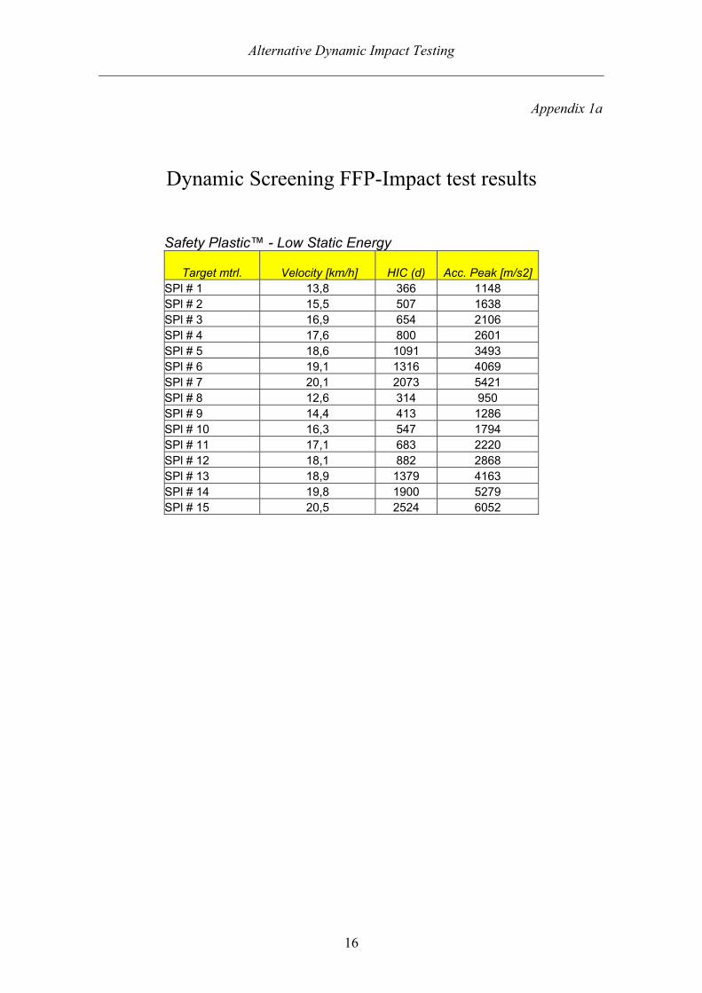
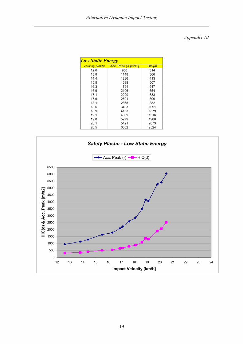
Low Static Energy Components (see appendix 1a, 1d, 1g, 1h)
Test results indicate a steadily escalating increase in acceleration peak with increased velocity. Visual component inspection after impact indicated large amounts of deformation even at low velocities. A possible change in trend is indicated at a velocity of approx 16,3 km/h, when the component seems to have come to a limit in the amount of energy it can absorb – although this is not thoroughly conclusive from the plotted data, visual inspection confirms this theory. All in all the plotted results create a comparatively well-behaved conclusive curve.
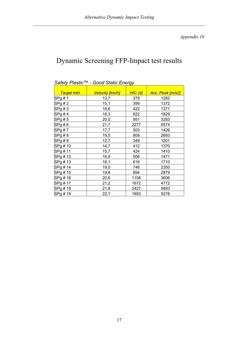
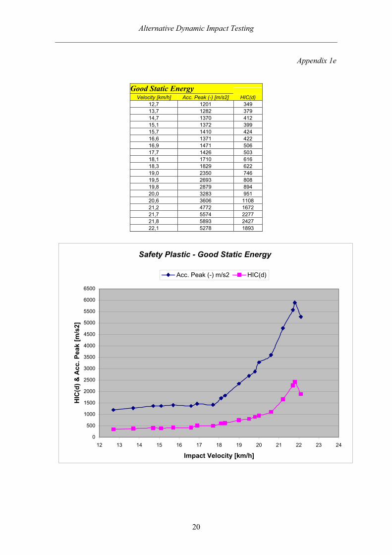
Good Static Energy Components (see appendix 1b, 1e, 1g, 1h)
Test results indicate that relatively moderate velocities of approx. 17,7 km/h and below create only a shallow increase in accelerations peak with increased velocity. At higher velocities than approx. 17,7 km/h this earlier trend is broken and acceleration peak values begin to escalate at a much greater rate. Visual inspection together with impact values indicates that in the region of 17,7 km/h the component has reached a limit in the amount of energy it can absorb. All in all the plotted results create a comparatively well-behaved conclusive curve.
Alternative Dynamic Impact Testing
12
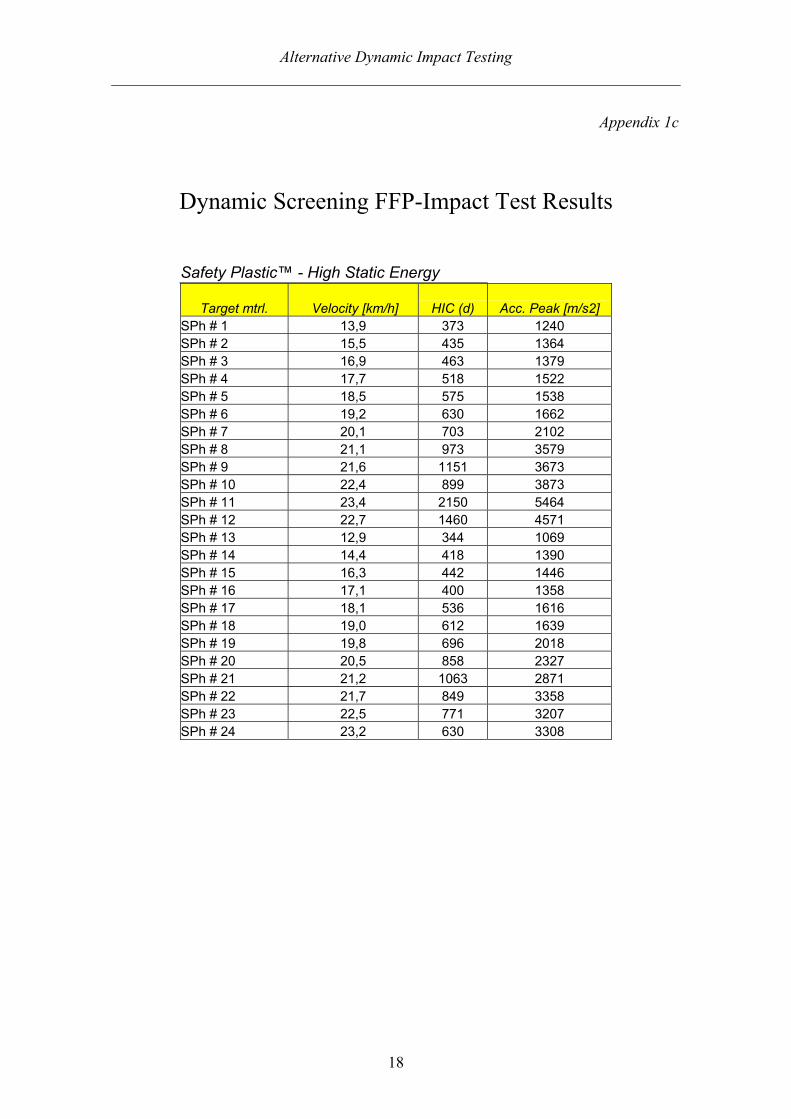
High Static Energy Components (see appendix 1c, 1f, 1g, 1h)
Once again, results indicate a relatively shallow increase in accelerations peak when velocities are kept below a certain, limit in this case approx. 19,2 km/h. At higher velocities this former trend is broken, further energy absorption is limited and as a consequence acceleration peak values begin to escalate at a much greater rate.
Noticeably, at velocities above approx. 21,1 km/h there are a considerable spread in results. The reason or reasons for this are not conclusively known but an investigation showed that production of component samples was not an unbroken series, as was the case for the “Low” and “Good” component samples, but was stopped and later started again. Impact samples SPh # 17 and SPh # 20 – SPh # 24 were produced some minutes earlier than the remaining samples tested in the same category – this can perhaps suggest why the plotted results are somewhat inconclusive and differ in behaviour from the two other curves.
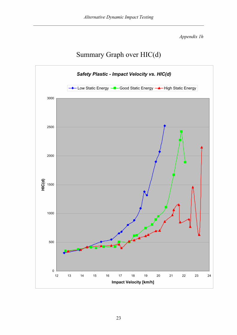
Category Analysis (see appendix 1g, 1h)
A comparison of all three categories plotted together in the summary graphs Accelerations Peak (-) and HIC(d) indicate a conclusive pattern of results. Each respective component effectively absorbs impact energy up to a certain limit. This limit, individually defined for each material at a certain velocity, differs rather greatly between the three categories. An impact at a velocity of approx 20,0 – 20,1 km/h resulted in a HIC(d) value of; 703 HIC(d) for High Static Energy, 951 HIC(d) for Good Static Energy, 2073 HIC(d) for Low Static Energy.
Please note that this method of testing although comparative in some ways to FMH-testing cannot be directly associated when it comes to specific HIC(d) values or acceleration peak values at certain velocities. But what we with good certainty can say is that the component deviation detected in this study would be reflected in results from in-vehicle testing.
5.4 Quasi-static Testing vs. Dynamic Testing The mechanics involved in the dynamic screening process differ from those in quasi-static screening. In the case of plastics the strain rate sensitivity is directly coupled to the kinetics of motion of the molecules [3]. And since the main working characteristics and main application for this component is one in a dynamic environment then dynamic screening should be preferred.
At the same time a quasi-static test is often much cheaper and simpler for the manufacturer to perform.
Alternative Dynamic Impact Testing
13
6 Recommendations Results from this study show an alarming difference between the three categories of component samples. Component tests provide evidence and begin to clarify the reason or reasons behind the relative span of HIC(d) values attained from in-vehicle testing.
It is my recommendation that in conjunction with the manufacturer a relevant nominal value of quasi-static energy criteria and a tighter tolerance span be established. How large this span should be depends a lot upon the limits of the production process. If nothing is done, and production and the quality control methods remain the same, then development engineers must be aware that a considerable amount of variation may be seen when in-vehicle testing is carried out.
Ideally a further study should be made to investigate if the dynamic screening process can be directly correlated to that of the quasi-static screening. If successful this correlation would be invaluable when attempting to set a nominal quasi-static energy absorption criteria and establish a relevant tolerance range – making quality control a much simpler process for the manufacturer.
7 Conclusions This newly developed method of dynamic testing although only tested for the first time and on a small scale, does seem an appropriate method to evaluate a components energy absorption characteristic. When neither a vehicle nor the use of a hybrid III headform are required this method becomes a relatively inexpensive and quick to procedure to perform. Furthermore the steel impacter and target-beam assembly allow for a reliable and repetitive dynamic test procedure preserving certain key elements of traditional FMH-testing but at the same time reducing the number of unknown factors and therefore creating a more conclusive method of screening.
8 Acknowledgements I would like to thank all my colleagues at the Department of Interior Safety Validation, and any other employees at Saab Automobile AB in Trollhättan, who have aided me during this thesis work. In particular great thanks to Annelie Ristoff who initiate this project and also to my adviser Henrik Kahra for his valuable input and good humour. I would also like to thank The Oakwood Group and their European Program Manager Ryan Brooks for providing the materials for this component study. A further thanks to my tutor Kjell Hurtig and examiner Mats Eriksson, both working at the University of Trollhättan/Uddevalla.

Alternative Dynamic Impact Testing
14
9 References
[1] Sounik, David F. et al. (1997) Head-Impact Testing of Polyurethane Energy-Absorbing (EA) Foams. SAE Technical Paper Series no.970160. Detroit: SAE Publications Group
[2] Laboratory Test Procedure for FMVSS 201U, U.S. Department of Transportation. National Highway Traffic Safety Administration. TP201U-01 April 3, 1998
[3] Castejón, L. et al, (1998) Energy Absorption Capability of Composite Materials Applied to Automotive Crash Absorbers Design. SAE Technical Paper Series no.980964. Detroit: SAE Publications Group
Additional studied literature
Society of Automotive Engineers, Inc.; SAE Technical Paper Series: 980972 A Comparative Study of Energy Absorbing Foams for Head Impact Energy
Management. 970165 Material Comparisons Using Free Motion Head (FMH) Impact and
Alternative Test Method. 960158 Dynamic Force Deflection Curves of Cellular Plastics Versus Impact Head
Shapes.

Alternative Dynamic Impact Testing
15
Appendices Appendix 1: FFP-Impact Test Results 1a. Dynamic Screening FFP-Impact Test Results … Low Static Energy 1b. Dynamic Screening FFP-Impact Test Results … Good Static Energy 1c. Dynamic Screening FFP-Impact Test Results … High Static Energy 1d. Results & Diagram … Low Static Energy 1e. Results & Diagram … Good Static Energy 1f. Results & Diagram … High Static Energy 1g. Summary Graph … Impact Velocity vs. Acceleration Peak 1h. Summary Graph … Impact Velocity vs. HIC(d) Appendix 2: Safety Plastic™ (reg) Parts and Data 2a. Ryan Brooks E-mail: … Safety Plastic™ (reg) Parts and Data 2b. Static Energy Data … SP-B152_Low Energy_030206.PDF 2c. Static Energy Data … SP-B152_Center Energy_030206.PDF 2d. Static Energy Data … SP-B152_High Energy_030206.PDF
Alternative Dynamic Impact Testing
16
Appendix 1a
Dynamic Screening FFP-Impact test results
Safety Plastic™ - Low Static Energy
Target mtrl. Velocity [km/h] HIC (d) Acc. Peak [m/s2] SPl # 1 13,8 366 1148 SPl # 2 15,5 507 1638 SPl # 3 16,9 654 2106 SPl # 4 17,6 800 2601 SPl # 5 18,6 1091 3493 SPl # 6 19,1 1316 4069 SPl # 7 20,1 2073 5421 SPl # 8 12,6 314 950 SPl # 9 14,4 413 1286 SPl # 10 16,3 547 1794 SPl # 11 17,1 683 2220 SPl # 12 18,1 882 2868 SPl # 13 18,9 1379 4163 SPl # 14 19,8 1900 5279 SPl # 15 20,5 2524 6052
Alternative Dynamic Impact Testing
17
Appendix 1b
Dynamic Screening FFP-Impact test results
Safety Plastic™ - Good Static Energy
Target mtrl. Velocity [km/h] HIC (d) Acc. Peak [m/s2] SPg # 1 13,7 379 1282 SPg # 2 15,1 399 1372 SPg # 3 16,6 422 1371 SPg # 4 18,3 622 1829 SPg # 5 20,0 951 3283 SPg # 6 21,7 2277 5574 SPg # 7 17,7 503 1426 SPg # 8 19,5 808 2693 SPg # 9 12,7 349 1201 SPg # 10 14,7 412 1370 SPg # 11 15,7 424 1410 SPg # 12 16,9 506 1471 SPg # 13 18,1 616 1710 SPg # 14 19,0 746 2350 SPg # 15 19,8 894 2879 SPg # 16 20,6 1108 3606 SPg # 17 21,2 1672 4772 SPg # 18 21,8 2427 5893 SPg # 19 22,1 1893 5278
Alternative Dynamic Impact Testing
18
Appendix 1c
Dynamic Screening FFP-Impact Test Results
Safety Plastic™ - High Static Energy
Target mtrl. Velocity [km/h] HIC (d) Acc. Peak [m/s2] SPh # 1 13,9 373 1240 SPh # 2 15,5 435 1364 SPh # 3 16,9 463 1379 SPh # 4 17,7 518 1522 SPh # 5 18,5 575 1538 SPh # 6 19,2 630 1662 SPh # 7 20,1 703 2102 SPh # 8 21,1 973 3579 SPh # 9 21,6 1151 3673 SPh # 10 22,4 899 3873 SPh # 11 23,4 2150 5464 SPh # 12 22,7 1460 4571 SPh # 13 12,9 344 1069 SPh # 14 14,4 418 1390 SPh # 15 16,3 442 1446 SPh # 16 17,1 400 1358 SPh # 17 18,1 536 1616 SPh # 18 19,0 612 1639 SPh # 19 19,8 696 2018 SPh # 20 20,5 858 2327 SPh # 21 21,2 1063 2871 SPh # 22 21,7 849 3358 SPh # 23 22,5 771 3207 SPh # 24 23,2 630 3308
Alternative Dynamic Impact Testing
19
Appendix 1d
Low Static Energy Velocity [km/h] Acc. Peak (-) [m/s2] HIC(d)
12,6 950 314 13,8 1148 366 14,4 1286 413 15,5 1638 507 16,3 1794 547 16,9 2106 654 17,1 2220 683 17,6 2601 800 18,1 2868 882 18,6 3493 1091 18,9 4163 1379 19,1 4069 1316 19,8 5279 1900 20,1 5421 2073 20,5 6052 2524
Safety Plastic - Low Static Energy
0
500
1000
1500
2000
2500
3000
3500
4000
4500
5000
5500
6000
6500
12 13 14 15 16 17 18 19 20 21 22 23 24
Impact Velocity [km/h]
HIC
(d) &
Acc
. Pea
k [m
/s2]
Acc. Peak (-) HIC(d)
Alternative Dynamic Impact Testing
20
Appendix 1e
Good Static Energy Velocity [km/h] Acc. Peak (-) [m/s2] HIC(d)
12,7 1201 349 13,7 1282 379 14,7 1370 412 15,1 1372 399 15,7 1410 424 16,6 1371 422 16,9 1471 506 17,7 1426 503 18,1 1710 616 18,3 1829 622 19,0 2350 746 19,5 2693 808 19,8 2879 894 20,0 3283 951 20,6 3606 1108 21,2 4772 1672 21,7 5574 2277 21,8 5893 2427 22,1 5278 1893
Safety Plastic - Good Static Energy
0
500
1000
1500
2000
2500
3000
3500
4000
4500
5000
5500
6000
6500
12 13 14 15 16 17 18 19 20 21 22 23 24
Impact Velocity [km/h]
HIC
(d) &
Acc
. Pea
k [m
/s2]
Acc. Peak (-) m/s2 HIC(d)

Alternative Dynamic Impact Testing
21
Appendix 1f
High Static Energy Velocity [km/h] Acc. Peak (-) [m/s2] HIC(d)
12,9 1069 344 13,9 1240 373 14,4 1390 418 15,5 1364 435 16,3 1446 442 16,9 1379 463 17,1 1358 400 17,7 1522 518 18,1 1616 536 18,5 1538 575 19,0 1639 612 19,2 1662 630 19,8 2018 696 20,1 2102 703 20,5 2327 858 21,1 3579 973 21,2 2871 1063 21,6 3673 1151 21,7 3358 849 22,4 3873 899 22,5 3207 771 22,7 4571 1460 23,2 3308 630 23,4 5464 2150
Safety Plastic - High Static Energy
0
500
1000
1500
2000
2500
3000
3500
4000
4500
5000
5500
6000
6500
12 13 14 15 16 17 18 19 20 21 22 23 24
Impact Velocity [km/h]
HIC
(d) &
Acc
. Pea
k [m
/s2]
Acc. Peak (-) m/s2 HIC(d)

Alternative Dynamic Impact Testing
22
Appendix 1g
Summary Graph over Acceleration Peak (-)
Safety Plastic - Impact Velocity vs. Acceleration Peak (-)
0
500
1000
1500
2000
2500
3000
3500
4000
4500
5000
5500
6000
6500
12 13 14 15 16 17 18 19 20 21 22 23 24
Impact Velocity [km/h]
Acc
. Pea
k (-)
[m/s
2]
Low Static Energy Good Static Energy High Static Energy
Alternative Dynamic Impact Testing
23
Appendix 1h
Summary Graph over HIC(d)
Safety Plastic - Impact Velocity vs. HIC(d)
0
500
1000
1500
2000
2500
3000
12 13 14 15 16 17 18 19 20 21 22 23 24
Impact Velocity [km/h]
HIC
(d)
Low Static Energy Good Static Energy High Static Energy

Alternative Dynamic Impact Testing
24
Appendix 2a
Ryan Brooks E-mail: SafetyPlastic(reg) Parts and Data
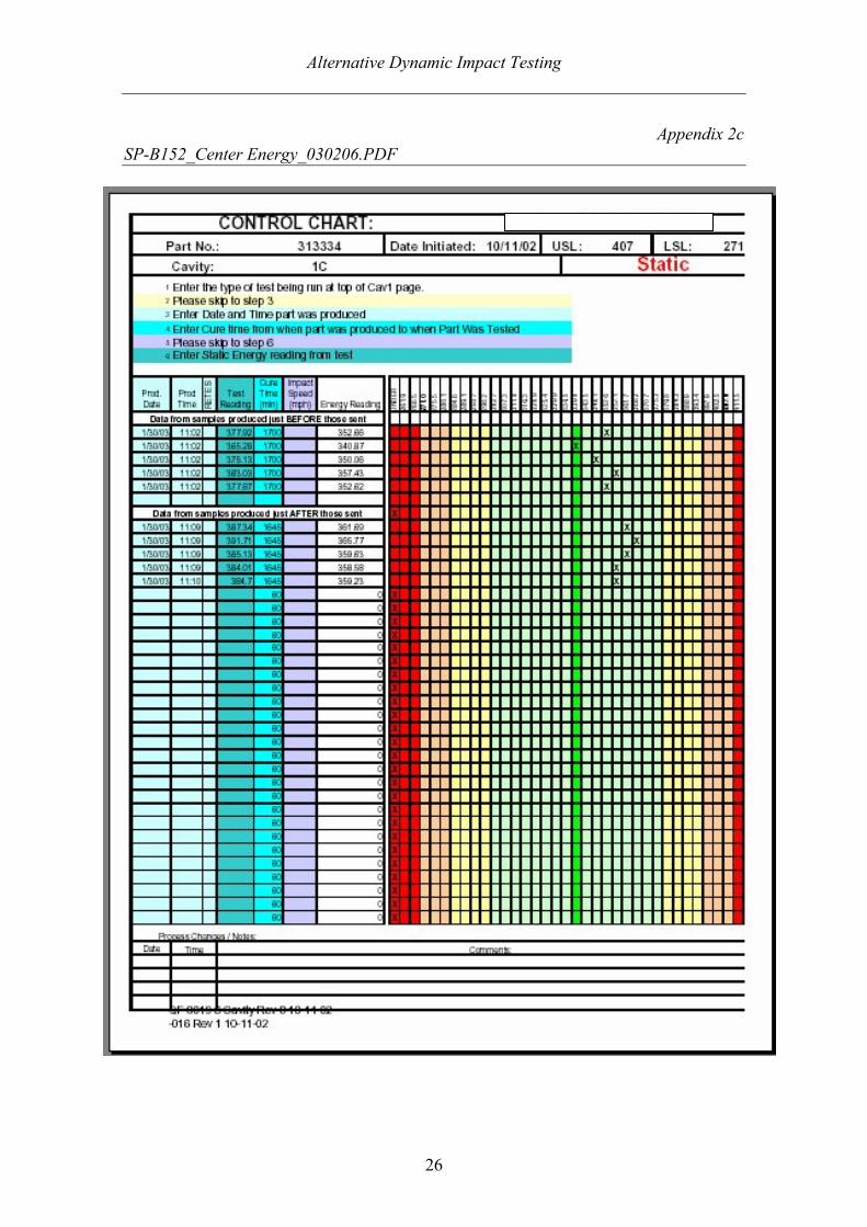
David, Hello. Per our conversation, I sent you 90 SafetyPlastic(reg) parts on February 4th. The FedEx tracking number is 791289535712. Thirty of these parts were formed near the center of our static energy absorption criteria, thirty were formed on the low edge of this criteria, and thirty were formed on the high edge of this criteria. Our static energy test is a destructive test, so I could not perform it on the parts that I sent you. Instead, I performed the test on five samples produced before and five samples produced after each batch that I sent you. I have attached copies of the data entered into our control chart document. The "green", "yellow", and "orange" colors all indicate acceptable parts. "Yellow" and "orange" are just indicators that our process should begin to be adjusted. The "red" color indicates failing parts. I tried to produce parts for you that were as close to the pass/fail border as possible. Please keep in mind that our normal production procedure probably would have rejected all of the high and low parts because some of the values were in the "red". Please give me an update on what testing you plan to accomplish. I am very interested to learn about the procedure and results. <<SP-B152_Center Energy_030206.PDF>> << SP-B152_High Energy_030206.PDF>> << SP-B152_Low Energy_030206.PDF>> Best Regards, Ryan Brooks European Program Manager The Oakwood Group, Inc. phone: (313) 561-7740 ext. 249 mobile: (313) 330-0074 [email protected]
"Brooks, Ryan" <[email protected]>
2003-02-06 16:28
To: "'Bourne, David'" <[email protected]> cc: "'Ristoff, Anneli'" <[email protected]> Subject: SafetyPlastic(reg) Parts and Data

Alternative Dynamic Impact Testing
25
Appendix 2b SP-B152_Low Energy_030206.PDF
Alternative Dynamic Impact Testing
26
Appendix 2c SP-B152_Center Energy_030206.PDF

Alternative Dynamic Impact Testing
27
Appendix 2d SP-B152_High Energy_030206.PDF