thesis on critical evaluation of ethiopian building …
TRANSCRIPT
THESIS ON CRITICAL EVALUATION OF ETHIOPIANBUILDING CODE STANDARD 2
BY
Wagaye Bekele
ADDIS ABABA, ETHIOIPIA
JUNE 2016
brought to you by COREView metadata, citation and similar papers at core.ac.uk
provided by National Academic Repository of Ethiopia

A THESIS SUBMITTED TO THE SCHOOL OF GRADUATE STUDIES OFADDISABABA SCIENCE AND TECHNOLOGEY UNIVERSITY IN PARTIALFULLFILLMENT OF THE REQUIREMENTS FOR THE DEGREE OF MASTEROF SCIENCE (M.Sc.) IN STRUCTURAL ENGINEERING
Approved by Board of Examiners
Dr. Suresh Borra ______________________
____________________
AdvisorSignatureDate
Dr.Ing. Temesegne Wondimu _____________________ ____________________
External ExaminerSignature Date
Dr. Mesay Daniel _____________________
____________________
Internal ExaminerSignatureDate
Ato: Yesuf Esleman ______________________ ____________________
Chairman Signature Date

Declaration
I, the undersigned, declare that this thesis is my Original work and all sources of materials used
for the thesis have been duly acknowledged.
Name: Wagaye Bekele
Signature: ____________________
Place: Addis Ababa Science and Technology University
Date of submission: June, 2016

4
ACKNOLEDGEMENT
Thanks to God for each and every success in my life and satisfactory accomplishment of this
project. He was endowed me courage and strength as well as precious health throughout my
school time and entire life as well.
I would like to extend my deepest gratitude and heartfelt appreciation to my advisor Dr. Suresh
Borra Associate Professors of Bahirdar University for his advice, guidance, and continuous
follow up, unreserved encouragement and constructive comments on the project that enabled the
author to grasp the necessary skill from the project with in short time.
I also extend my gratitude to post graduate coordinatorsDr. Habetamu Hailu,Dr. Habetamu
Itefa and Dr. MesayDaniel for their cooperation of all kind.
I would like to thank my sponsor ship Ethiopian Road Authority for the financial support and
also I would like to express my warm gratitude to all DRs. who have given Post graduate
courses.
I am also gratefully acknowledging the contributions of all those individuals who had contributed
me one way or the other.
Lastly I express my warm gratitude to my family Menbermariam, Dawit and Yosef for their
special support and standing in solidarity with me.

5
Abbreviation:Note: The abbreviation used is based on ISO 3898:1987 Latin upper case lettersA Accidental actionA Cross sectional areaAc Cross sectional area of concreteAs Cross sectional area of reinforcementAs,min minimum cross sectional area of reinforcementAsw Cross sectional area of shear reinforcementD Diameter of mandrelDEd Fatigue damage factorE Effect of actionEc,Ec(28) Tangent modulus of elasticity of normal weight concrete at a stress of c =
0 and at 28 daysEc,eff Effective modulus of elasticity of concreteEcd Design value of modulus of elasticity of concreteEcm Secant modulus of elasticity of concreteEc (t) Tangent modulus of elasticity of normal weight concrete at a stress of c=
0 and at time tEs Design value of modulus of elasticity of reinforcing steelE Bending stiffness EQU Static equilibriumEQU Static equilibriumF ActionFd Design value of an actionFk Characteristic value of an actionGk Characteristic permanent action Second moment of area of concrete sectionL LengthM Bending momentMEd Design value of the applied internal bending momentN Axial forceNEd Design value of the applied axial force (tension or compression)Qk Characteristic variable actionQfat Characteristic fatigue load R ResistanceS Internal forces and moments

6
S First moment of areaSLS Serviceability limit stateT Torsional moment
TEd Design value of the applied torsional momentULS Ultimate limit stateV Shear forceVEd Design value of the applied shear forceLatin lower case lettersa Distancea Geometrical dataΔa Deviation for geometrical datab Overall width of a cross-section, or actual flange width in a T or L beambw Width of the web on T, I or L beamsd Diameter; Depthd Effective depth of a cross-sectiondg largest nominal maximum aggregate sizee Eccentricityfc Compressive strength of concretefcd Design value of concrete compressive strengthfck Characteristic compressive cylinder strength of concrete at 28 daysfcm Mean value of concrete cylinder compressive strengthfctk Characteristic axial tensile strength of concretefctm Mean value of axial tensile strength of concretef0.2k Characteristic 0.2% proof-stress of reinforcementft Tensile strength of reinforcementftk Characteristic tensile strength of reinforcementfy Yield strength of reinforcementfyd Design yield strength of reinforcementfyk Characteristic yield strength of reinforcementfywd Design yield of shear reinforcementh Heighth Overall depth of a cross-sectioni Radius of gyrationk Coefficient; Factorl (or l or L) Length; Spanm Massr Radius

7
1/r Curvature at a particular sectiont Thicknesst Time being considered t0 the age of concrete at the time of loadingu Perimeter of concrete cross-section, having area Acu,v,w Components of the displacement of a point
x Neutral axis depthx,y,z Coordinatesz Lever arm of internal forcesGreek lower case letters Angle; ratio Angle; ratio; coefficient Partial factorA Partial factor for accidental actions AC Partial factor for concreteF Partial factor for actions, FF,fat Partial factor for fatigue actionsC,fat Partial factor for fatigue of concreteG Partial factor for permanent actions, GM Partial factor for a material property, taking account of uncertainties in the
material property itself, in geometric deviation and in the design modelused
Q Partial factor for variable actions, Qf Partial factor for actions without taking account of model uncertaintiesg Partial factor for permanent actions without taking account of model
uncertaintiesm Partial factors for a material property, taking account only of uncertainties
in the material property Increment/redistribution ratio Reduction factor/distribution coefficientc Compressive strain in the concretec1 Compressive strain in the concrete at the peak stress fccu Ultimate compressive strain in the concrete Angle Slenderness ratio
8
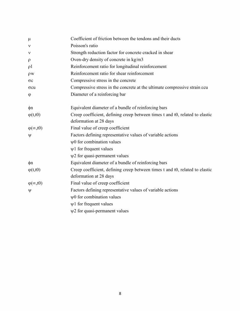
Coefficient of friction between the tendons and their ducts Poisson's ratio Strength reduction factor for concrete cracked in shear Oven-dry density of concrete in kg/m3l Reinforcement ratio for longitudinal reinforcementw Reinforcement ratio for shear reinforcementc Compressive stress in the concretecu Compressive stress in the concrete at the ultimate compressive strain cu Diameter of a reinforcing bar
n Equivalent diameter of a bundle of reinforcing bars(t,t0) Creep coefficient, defining creep between times t and t0, related to elastic
deformation at 28 days(,t0) Final value of creep coefficient Factors defining representative values of variable actions
0 for combination values1 for frequent values2 for quasi-permanent values

9
List of tables:
Table-2.0 Concrete modulus of elasticityTable 2.2 Combination factors ( factors)Table-3.0 Values of the coefficient Table-3.1 Transverse reinforcement in the lap zone.Table-3.2 Minimum mandrel diameter to avoid damage to reinforcement.Table-3.3 Values ofTable-3.4 Minimum cover requirements with regard bond.Table-3.5 Recommended structural classificationTable-3.6 Environmental requirement forTable-4.0 Beam valuesTable-4.1 Fire resistance requirements for beamsTable-4.2 Slenderness limits for beamsTable-4.3 Minimum percentage of steelsTable-5.0 Slabs valuesTable-5.1 Minimum percentage of reinforcementTable-5.2 Distribution of design momentTable-6.0 Column valuesTable-6.1 Fire resistance for columnsTable-6.2 Recommended minimum longitudinal reinforcement area in cast in place bored
pilesTable-7.0 BeamsTable-7.1 Recommended values of Table-7.2 Values for “K” and “

10
List of Figures:Fig-2.0 Stress-strain diagrams of typical reinforcing steel.Fig-3.0 Relation between the required and maximum anchorage length.Fig-3.1 Distribution of bond stress along the transmission lengthFig-3.2 Transfer of forces between bars in a lap spliceFig-3.3 Adjacent laps.Fig-3.4 Percentage of lapped bars in one lapped section.Fig-3.5 Transverse reinforcement for lapped splicesFig-3.6 Lapping of welded fabric.Fig-3.7 Additional reinforcement in an anchorage for large diameter bars where there is
no transverse compressionFig-3.8 Basic anchorage lengthFig-3.9 Values of for beams and slabs.Fig-3.10 Values of “K” for beams and slabs.Fig-3.11 Anchorage of links.Fig-3.12 Welded transverse bar as anchor aging deviceFig-3.13 Anchorage of bottom reinforcement at end supports.Fig-3.14 Longer bond and anchorage length of reinforcing bars.Fig-3.15 Bar bent inwards to avoid radial forces on thin concrete cover.Fig-3.16 Anchorage of widely staggered bars in a bundle.Fig-3.17 Specification of cover to reinforcement. Fig-3.18 Concrete cast directly on earth-nominal cover from average soil level.Fig-3.19 Concrete cast on an adequate blinding layer.Fig-4.0 Effective span for different support conditions.Fig-4.1 Definition of “ for calculation of effective flange width.Fig-4.2 Effective flange width parameters.Fig-4.3 Transverse reinforcement anchorage bonds.Fig-4.4 Distribution of tension reinforcement in flanged cross section.Fig-4.5 Anchorage at intermediate supports.Fig-4.6 Curtailment of reinforcement for various supports.Fig-4.7 Shear reinforcement.

11
Fig-4.8 Recommended shapes for torsion reinforcement.Fig-5.0 The normal reinforcement provided for a slab may act as edge reinforcement.Fig-5.1 Edge and corner column reinforcement. Fig-5.2 Punching shear reinforcement. Fig-5.3 Control perimeter nears an opening.Fig-6.0 Column reinforcement restraining.Fig-6.1 Compressed area increasing the anchorage capacity.Fig-6.2 Orthogonal reinforcement in circular spread footing on soil.Fig-6.3 Splitting reinforcement in footing on rock.TABLE OF CONTENTS PageAcknowledgment I
Abbreviation IIAbstract XIICHAPTER ONE 1I. INTRODUCTION 11.1. Introduction 11.2. General behavior of reinforced concrete structures 11.3. Statement of the Problem 31.4. Objective 31.4.1. General objective 31.4.2. Specific objective 31.5. Methodology 41.6. Scope 41.7. Limitation 41.8. Literature review. 5CHAPTER TWO 6BASIC DESIGN PRINCIPLES 62.1. Introduction 62.2. Basic Design Parameters 72.2.1. Characteristic Values 72.2.2. Design Values 82.2.2.1. Concrete 92.2.2.2. Reinforcing steel 102.2.2.3. Partial Factors 122.3. Different settlements /Movements 132.3.1. Ultimate limit states 132.3.2. Serviceability limit states 142.4 .Shrinkage and creep 14 2.4.1. Serviceability limit states 14 2.4.1.1. Creep 142.4.1.2. Shrinkage of concrete 152.4.2. Partial factors for shrinkage action 15

12
2.4.3. Ultimate limit states 15CHAPTER THREE 17BOND and ANCHORGE 173.1. Introduction 173.2. Anchorage of bottom reinforcement at end supports 193.3. Lapping of longitudinal reinforcement 213.3.1. Laps and mechanical couples 213.3.1.1. Laps 22 3.3.1.2. Location and position 223.3.1.3. Lapping in tension and compression 223.3.1.4. Lap length 23 3.3.1.5. Transverse reinforcement in the lap zone 243.4. Spacing of bar 273.4.1. Clear distance 273.4.2. Spacers and chairs 283.5. Permissible mandrel diameters for bent bars 293.6. Anchorage of longitudinal reinforcement 313.6.1. Reinforcing bars, wires or welded mesh fabrics 313.6.2. Design anchorage length 323.6.3. Anchorage of links and shear reinforcement 353.7. Surface reinforcement 393.8. Bundled bars 403.9. Concrete cover 42CHAPTER FOUR 50STRUCTURAL ELEMENT 504.1. Beams 504.2. Other code provisions 514.3. EBCS provision 534.3.1. Elements of structure 534.3.2.Reinforcement 534.3.2.1 Minimum reinforcement 534.3.2.2. Design of supports 544.3.3. Geometric data 554.3.3.1. Effective spans of beams and slabs 554.3.3.2. Effective width of flanges 574.3.4. Transverse reinforcement 584.4. T- beams 594.4.1. Placing of tension reinforcement in flanged cross section 594.4.2. Curtailment of longitudinal reinforcement 604.4.3. Anchorage of bottom reinforcement 614.3.3.1. At end support with little or no end fixity 624.3.3.2. Anchorage of bottom reinforcement at intermediate supports 624.4.4. Simplified detailing rules for beams 65

13
4.5. Shear reinforcement 664.6. Torsion reinforcement 674.7. Deep beams 68CHPTER FIVE 69SLABS 695.1. Introduction 695.2. Flexural reinforcement 725.2.1. Spacing of bars 735.2.2. Corner reinforcement 745.3. Shear reinforcement 745.4. Flat slabs 745.4.1. Punching shear reinforcement 755.4.1.1. Load distribution and basic control perimeter 77CHAPTER SIX 79COLUMNS 796.1. Introduction 796.2. Column reinforcement 816.2.1. Longitudinal reinforcement 816.2.2. Transverse reinforcement 826.2.2.1. Spacing 836.3. Walls 846.3.1. Introduction 846.3.2. Reinforcement 846.3.2.1. Vertical reinforcement 846.3.2.2. Horizontal reinforcement 856.3.2.3. Transverse reinforcement 856.3.3. Foundation of pile cap 856.3.3.1. Reinforcement 856.3.4. Columns and wall footings 866.3.4.1. Reinforcement 866.3.5. Bore piles 886.3.6. Cast in place piles 89CHAPTER SEVEN 90SERVICEABILITY LIMIT STATE 907.1. Introduction 907.2. Stress limitation 907.2.1. Concrete 907.2.2. Steel 917.3. Crack control 917.3.1. General consideration 917.3.2. Limitation 927.3.3. Flexural cracking 937.4. Deflection control 93
14
7.5. Environmental condition 98Discussions 99Conclusion 102Annex 103Reference 105
ABSTRACT
Design of a concrete structure is a step by procedure beginning with estimation of the loadsacting on the structural system, preliminary proportioning of relative stiffness’s of the structuralsystem, carrying out a detailed and often iterative general structural analysis, followed by thesizing or proportioning of the members and concluding with the detailing process. Whileengineers are usually well trained in analysis procedures and the basic mechanics of structuralconcrete, there is not a general methodology for detailing. This often presents the designer withnumerous difficulties. The different codes and standards propose empirical recommendations forsome specific applications. However the design standards cannot include the innumerable detailsthat may arise.
Structural design and construction has the objective to build safe durable, serviceable,economical and aesthetic structures. The translation of design into correspondingly high qualitystructure necessitates good detailing and construction practices. The limit state method designprimary aim is to minimize the probability of failure to an acceptable low value. In this contextattainment of limit state is called failure. Limit states imply those conditions where by a structureceases to fulfill the functions for which it has been designed. By using limit states method(allowing for inelasticity and moment redistribution) with partial safety factors, with higherstrength materials, for higher stresses, modern structures are designed. And also methods ofanalysis and design have become more sophisticated and accurate and the benefit of conservationin built in approximate methods is no longer available. Therefore these results in taller structuresand longer spans more slender members and thinner slabs and walls and are built at faster pace.
They are therefore more flexible (in terms of deflections) and are more crack prone as comparedwith the old structures which used to be low in height had thicker(stockier) members were lightlystressed and were built at slower place. Thus serviceability criteria assume for greater importancein modern structures. As a result of the introduction of limit state method of design for reinforced

15
concrete structures and the concept of development length has become extremely important asmany of the design requirements are to be met through detailing.
The design and building processes would subjected to substantial impact from constructiondetails. Also it affects concrete structure durability and maintenance. Around concrete structuresthe problems arising are attributable to design stage and due to lack of or errors in constructiondetails. Their share is 50% and 50%.
Knowledge in four areas synthesized for good detailing:1) Knowledge on structural concrete engineering underlying theory2) Professional practice in on-site.
3) Laboratory trials information from experiments.4) Forensic engineering studies experience.
Detailing practices, construction practices, quality control in construction, building failurescauses and prevention of cracks/leakage in buildings etc. are all large enough topics. Not all thesetopics strictly within the scope of this book (Detailing manual). As such an attempt is made hereonly to draw attention to some of the major and most common causes of failure pertaining to thedesign(and construction) of reinforced concrete buildings. In Detailing generally included are theproperties of single and bundled bars, selection of beam reinforcement, and crack controlrequirements, development length of bars and minimum radii of bends. Therefore this book willbe useful to concrete design engineers, field engineers and students of civil engineers.
Key words: Relative Stiffness, Detailing, mechanics of structural concrete, Durable, codes, limit state,Forensic engineering

16
Chapter-1
Introduction
1.1. Introduction
In the beginning of year 1995(G.C) Ministry of works and urban development prepared Building
code standards of general application. The purpose of these standards to serve as nationally
recognized documents, the application of which is deemed to ensure compliance of buildings
with the minimum requirements for design, construction and quality of materials set down by the
“National Building Code”.
The major benefits to be gained in applying these standards are harmonization of professional
practice and ensuring of appropriate levels of safety, health and economy with due consideration
of the objective conditions and needs of the country.
Intended response of the structure from the safety, health and economy can be achieved
essentially by providing proper detailing .And also important that fundamental theory and
required structural behavior of reinforced concrete structures are known in order to reduce the
risk of incorrect interpretations and unacceptable solutions. Therefore it is of great interest to
know the background of EBCS-2 in order to implement the rules in correct manner. And also it is
important to investigate how the structural engineers are interpreting rules and applying them to
the practical conditions.
1.2.General behavior of reinforced concrete structures:
In order to know how to design a structural member and what analysis approaches that are valid,
it is important to understand the typical response of the structural member in reinforced
concrete.This response can be divided into four different stages.
1) Un cracked stage
2) Cracked stage
3) Yielding and

17
4) Collapse
1)Un cracked stage
In the un cracked stage the influence of reinforcement is small(i.e., homogeneous material can
normally be assumed in analysis). The relation between the load and deformation is linear elastic
(i.e., in case of bending the curvature increases linearly with the applied bending moment).
The linear elastic analysis results one unique solution independent of load, hence it is only the
magnitude of stresses that increases with increased loading. Since the sections are un cracked the
stresses is constant even when the load increases but the shape of the stress field remains (i.e.,
Global response also is be linear elastic)
2) Cracked
Since stiffness depends on whether the section is cracked or un cracked, there will be drastic
changes of stiffness when cracking occur. In the cracked regions the stiffness is dependent on the
reinforcement amount and its arrangement. In this stage the relation between the load and
deformation is no longer linear.
In statically indeterminate structures stiffer regions attract forces hence redistribution of moment
takes place, stress redistribution due to cracking. The movement thus decreases in the cracked
regions and increases in the un cracked regions and influences also the global response.
As the load increases cracking of the structural member continue until the member becomes fully
cracked. As a result the stress field configuration differs from that in the un cracked state.
Due to cracking and continuous change of stiffness distribution, reinforced concrete members
have a nonlinear response in the cracked stage. The ultimate stage is reached when one of the
materials concrete or steel reaches nonlinear behavior, for instance when the reinforcement starts
to yield in a region of the member.

18
3) Yielding and collapse
Yielding of a region will drastically affect the response of that region as well as the global
response. However this does not mean that the capacity of the member reached. For statically
indeterminate structures the load can still be increased due to plastic redistribution even though
significant increase of the moment in the yielding section is not possible .The plastic
redistribution due to the plastic deformation of the yielding region which behaves like a plastic
hinge. When load increases one or more plastic regions will develop and when plastic resistance
is reached in some critical regions it determines the resistance of the whole structural member. A
collapse mechanism forms when a critical member of plastic hinges develop. However a
condition is that the needed plastic rotations in the first hinge(s) can develop. Otherwise a
premature failure a hinge occurs before a collapse mechanism is formed. To analyze the
equilibrium conditions in the collapse stage an ideally plastic behavior of the sections can be
assumed and the force distributions can be solved by means of theory of plasticity.
1.3 .Statement of the problem:
In order to fill the gaps of EBCS-2 with EBCS draft codes by comparing with other codes and to
facilitate the use of EBCS-2. Along with diagrammatic representation.
1.4.Objectives:
1.4.1. General objective
To fill the ambiguities and gapsof EBCS code..
1.4.2. Specific objectives.
To develop a detailing guide
To understand the background for the rules of EBCS-2
To investigate the current practice of EBCS-2 in applying to the structures.

19
1.5.Methodology
A more detailed literature study to look into the background of the highlighted areas looked into
.Literature search among articles and publications. To get further information and increase the
understanding codes and related publications from other countries codes like EURO, ACI, AS
and IS.
1.6.Scope:
In depth understanding of the EBCS codes provisions , identify the ambiguities and gaps in the
EBCS code , those ambiguities and gaps will be filled with literature review and studying the
developed countries procedures researched and reported. And this study is aimed to develop a
relatively simple approach for detailing.
This detailing code book is concentrated to the common structural elements like Beams, slabs,
columns and walls, along with foundations. And also drawn the attention of the ultimate limit
state and serviceability limit state. In order to enhance the quality of this thesis while explaining
the background for various clauses , the concepts are correlated with the advanced codes like
European code(EC), American concrete institute(ACI) code, Australian code(AS) and Indian
standard(IS) code for those not provided by the EBCS code.
1.7.Limitations:
No practical experiments or numerical modeling using FE programs have been executed
Plain, Pre stressed and prefabricated concrete should be left out in order to reduce the
numberof issues into a manageable amount.

20
1.8.Literature review:
Robin whittle (2013), Failures in concrete structures (case studies in reinforced and pre stressed
structures) revealed various causes of failuresof the reinforced concrete structures, they are
particularly related to
Failures due to misuse of code of practice clauses
Failures due to inappropriate extrapolation of code of practice clauses
Problems and failures due to poor detailing etc.
In this he found that poor detailing is often connected with a lack of sufficient design thought and
accompanied by poor workmanship in construction .The combination can lead to structural
failure.
He made a remarkable comment on codes suggested minimum reinforcement and it’s relation
with cracking. Codes of practice stipulate a minimum amount of reinforcement based on the
tension strength of the concrete. But the tension yield strength of the reinforcement should be at
least equal to the tension strength of the concrete when minimum reinforcement is provided and
it related to cracking also.
My study aimed to fill EBCS gaps and develop a relatively simple approach for detailing.

21
Chpater-2
Basic Design Principles
2.1. Introduction
The aim of limit state design is to ensure that the structure being designed remains safe and
serviceable throughout its life and what it does not become unfit for the use for which it was
intended, i.e., it does not reach a “limit state” by violating one or more of the criteria governing
it’s performance and use.
The limit state associated with the maximum load carrying capacity of the structure i.e., its safety
is called the limit state of collapse or the ultimate limit state whereas those associated with the
performance of the structure under service loads are called the limit states of serviceability.
The principal limit states to be checked for in design correspond to the following conditions.
1) Limit state of collapse
The whole structure or part of it may collapse as a result of failure one or more critical
sections, elastic or plastic instability, overturning, fatigue effects etc. Design for the
ultimate strength in flexure, shear etc. corresponds to this limit state.
2) Limit state of deflection:
The structure may deflect excessively, adversely affecting its serviceability performance
3) Limit state of cracking
Excessive cracking of concrete may be determined to the appearance and integrity of the
structure and may lead to corrosion of reinforcement.

22
In addition to these limit states, in special cases the structure may have to be checked for other
effects such as vibration, durability, fire resistance etc.
Any assessment of the safety and serviceability of a structure must take into account the
variations in the imposed loads and in the strengths of the materials of which the structure is
composed as well as the inadequacies in the methods of analysis, design and construction. Safety
and serviceability can therefore be meaningfully expressed only in terms of the probability that
the structure will not reach a limit state. Accordingly the design process must ensure that the
probability of a limit state being attained is kept at an acceptably low value for the type of
structure in question.
However such a strict probabilistic design procedure is not possible at present principally
because on the one hand there is a lack of statical data concerning the design variables and on the
other a number of effects not readily amenable to statcial treatment modify the loading and the
resistance of the members even where these are derived statically. The design approach
recommended in the code is therefore “Semi-Probabilistic” i.e., one which treats only the basic
design variables in a probabilistic manner and covers the other uncertain influences through
“partial safety factors”. This is achievedthrough the concept of “characteristic” and “design
values” as discussed below.
2.2. Basic design Parameters:
The design process essentially consists in ensuring that the resistance of a member , expressed in
terms of the strengths of its component materials, is greater than the forces acting on it, expressed
in terms of the loads. Hence the design data may be divided into two basic groups:
1) For loads
2) The material strengths.

23
2.2.1. Characteristic values:
These account for the normal statical variations in the basic design data and are expressed as
Characteristic value = mean value (k * Standard deviation)
Where the factors “k” ensures that the probability of the actual values being either greater(as in
the case of loads) or smaller(as in the case of material strengths) than the characteristic value is
kept at an acceptably low level.
For material strengths, that code defines the characteristic value as that below which not more
than 5% of the test results fall. This definition implies a value of k=1.64. Accordingly the
characteristic strength of materials is given by the following expression
Characteristic strength(clause 3.12(1))
Mean strength
Standard deviation
The analogues definition of characteristic load would be difficult to operate in practice in the
absence of complete statically data on the variability of loads. Hence for the present it is
necessary to assume that the characteristic load is that specified in the appropriate loading
standard as stipulated in the code.
2.2.2. Design values:
A number condition such as accidental overloads and errors in design and construction modify
adversely the load effects and member resistances so that their eventual magnitudes in the actual
structure are different from those derived on the basis of the characteristic values. Such effects
are accounted for by modifying the characteristic values through “Partial Safety factors” for each
limit state, to give the design values appropriate to that limit state. Thus

24
Design strength of material =
Design Load =
Where
Partial safety factor for materials
Partial safety factor for loads.
It is these design values that should be considered in formulating the design equations.
2.2.2.1 .Concrete
Design compressive and tensile strengths (Clause 3.16)
(1) The value of the design compressive strength is defined as
Where:
is the partial safety factor for concrete, and
is the coefficient taking account of long term effects on the compressive strength and of
unfavorable effects resulting from the way the load is applied.
Note: For use of cc refer to the national annex,
The recommended value is 0.85.
EC recommends a value of1.
(2) The value of the design tensile strength,is defined as
Where:
is the partial safety factor for concrete, and
is a coefficient taking account of long term effects on the tensile strength and of
unfavorable effects, resulting from the way the load is applied.
Note: - For use of refer to the national annex,
The recommended value is 0.85.
EC recommends a value of1.

25
For concrete Poisson’s ratio may be taken =0.2 for uncracked concrete and “0” for cracked
concrete. (Clause 3.13(4))
Unless more accurate information is available, the linear coefficient of thermal expansion may be
taken equal to (Clause 3.13(5)
Compressive strength class: Compressive strength class defines 28 days compressive strength
C32/40 means
i) Letter for type of concrete
C- Normal and heavy weight
LC- Light weight
ii) 32- Minimum characteristic of 150 mm dia by 300mm cylindrical strength
iii) 40-Minimum characteristic cube strength
Concrete Modules of Elasticity: (From Table 7.2 of BS 8110 Part-2, 1985):
Typical mean values for the static modules of elasticity at 28 days for normal weight concrete
are given
Typical range for the static modules of elasticity at 28 days of normal weight of concrete
,
Mean value Typical range
20 24 18 to 30
25 25 19 to 31
30 26 20 to 32
40 28 22 to 34
50 30 24 to 36
60 32 26 to 38
Table-2.0Concretemodules of elasticity
2.2.2.2. Reinforcing steel:
26
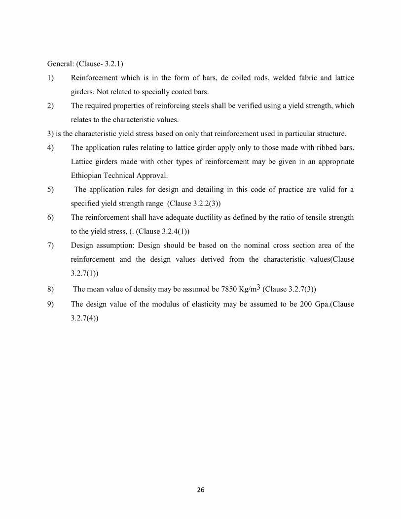
General: (Clause- 3.2.1)
1) Reinforcement which is in the form of bars, de coiled rods, welded fabric and lattice
girders. Not related to specially coated bars.
2) The required properties of reinforcing steels shall be verified using a yield strength, which
relates to the characteristic values.
3) is the characteristic yield stress based on only that reinforcement used in particular structure.
4) The application rules relating to lattice girder apply only to those made with ribbed bars.
Lattice girders made with other types of reinforcement may be given in an appropriate
Ethiopian Technical Approval.
5) The application rules for design and detailing in this code of practice are valid for a
specified yield strength range (Clause 3.2.2(3))
6) The reinforcement shall have adequate ductility as defined by the ratio of tensile strength
to the yield stress, (. (Clause 3.2.4(1))
7) Design assumption: Design should be based on the nominal cross section area of the
reinforcement and the design values derived from the characteristic values(Clause
3.2.7(1))
8) The mean value of density may be assumed be 7850 Kg/m3 (Clause 3.2.7(3))
9) The design value of the modulus of elasticity may be assumed to be 200 Gpa.(Clause
3.2.7(4))

27
Figure2.0.Stress-strain diagrams of typical reinforcing steel (absolute values are shown
for the tensile stress and strain
Economy in use of steel:
The type of steel used is generally specified by the designer but bear in mind that up to rd of the
mass of steel can be saved by using high tensile steel instead of mild steel. Furthermore as the
rates for small diameters are higher than those for large diameter, it is desirable to use the largest
available size of bar within the design requirements. Larger bars are also produce stiffer cages
and are not displaced.
2.2.2.3. Partial factors:
1) For Fatigue loads(Clause 2.4.2.3(1))
The partial factor for fatigue loads
2) For Materials (clause 2.4.2.4(1))

28
a) Ultimate limit state: (Table 2.1N, EBCS-2 partial factors for materials
for ultimate limit states)
Design
situation
Persistent and
Transient
1.5 1.15 1.15
Accidental 1.2 1.0 1.0
Table-2.1, Partial factors for materials for ultimate limit states
There are three types of design situations:
i) Persistent- Corresponding to normal use
ii) Transient- For example during construction, refurbishment or repair
iii) Accidental- Such as fire, explosion or earthquake.
In fatigue verification the partial factors for persistent design situations given in table 2.0 are
recommended for the values of
b) Serviceability limit state
not covered by EBCS is 1.0
Partial factors for material (For Foundations)
For concrete () - for calculation of design resistance of cast in place without permanent
casing.Values of above table multiplied by
=1.1(National Annex.)
Extract from NAD Table-2:
Variable

29
Action Building type
Imposed
f l o o r
loads
Dwellings 0.5 0.4 0.2
Other occupancy classes 0.7 0.6 0.3
Parking 0.7 0.7 0.6
Imposed
r o o f
loads
All occupancy classes 0.7 0.2 0.0
W i n d
loads All occupancy classes 0.7 0.2 0.0
Table-2.2 Combination factors (:
Note: NAD: National Application Document which is issued by the member countries (BSI)
2.3. Differential settlements/movements:-
Differential settlements/movements of the structure due to soil subsidence should be classified as
permanent action Gset , which is introduced as such in combinations of actions
Note: Where differential settlements are taken into account appropriate estimate values of
predicted settlements may be used.
2.3.1. Ultimate limit states:
It is considered
1) Fatigue conditions
2) In the verification of stability where second order effects are of importance etc. It is not
considered in other cases provided that the ductility and rotation capacity of the elements are
sufficient

30
2.3.2. Serviceability limit state:
The effects of differential settlements should generally be taken into account for the verification
for serviceability limit states
Where differential settlements are taken into account a partial safety factor for settlement effects
should be applied. (Safety factors Annex of EBCS EN 1990:2013)
2.4. Shrinkage and creep:
2.4.1 Serviceability limit state:
Shrinkage and creep are time dependent of concrete. Their effects should generally be taken into
account for the verification of serviceability limit states.
2.4.1.1. Creep:
Where a stress is applied to a concrete specimen and kept constant the specimen shows an
immediate strain followed by a further deformation which progressing at a diminishing rate may
become several times the original immediate strain. The immediate strain is often referred to as
the elastic strain is often referred to as the elastic strain and the subsequent time dependent strain
referred to as the creep strain or simply the creep. That part of strain which is immediately
recoverable upon removal of the stress is called the elastic recovery and the delayed recovery the
creep recovery. The elastic recovery is less than the elastic strain the creep recovery is much less
than the creep.
2.4.1.2. Shrinkage of concrete:
31
Drying of concrete in air results in shrinkage, while concrete kept under water swells. When the
change in volume by shrinkage or by swelling is restrained stresses develop. In reinforced
concrete structures the restraint may be caused by the reinforcing steel by the supports or by the
difference in volume change of various parts of the structure. The symbol will be used for the
free (Unrestrained) strain due to shrinkage or swelling. In order to comply with the sign
convention for other causes of strain is considered positive when it represents elongation. Thus
shrinkage of concrete is negative quantity. Stresses caused by shrinkage are generally reduced by
the effect of creep of concrete. Thus the effects these two simultaneous phenomenon must be
considered in stress analysis. For this purpose the amount of free shrinkage and an expression for
its variation with time are needed.
Shrinkage starts to develop at a time “ when moist curing stops.
The strain that develops due to free shrinkage between and a later instant “t” may be expressed
as follows.
Total shrinkage that occurs after concrete hardening up to time infinity.--- it epends upon the
quality of concrete the ambient air humidity.
2.4.2.Partial factor for shrinkage action:
Where consideration of shrinkage action is required for ultimate limit state a partial factor
should be used. (Clause 2.4.2.1 EBCS draft code)
2.4.3. Ultimate limit states:
Shrinkage and creep to be considered
1) In the verification of ultimate limit state of stability where second order
effects are of importance.
Shrinkage and creep need not be considered.
1) In other cases provided that ductility and rotation capacity of the elements are sufficient.

32
When creep is taken into account its design effects should be evaluated under the quasi
permanent combination of actions irrespective of the design situation considered i.e.
persistent , transient or accidental(clause 2.3.2.2)
In building structures temperature and shrinkage effects may be omitted in Global analysis
provided joints are incorporated at every distance “djoint“to accommodate resulting
deformations. The recommended value of djoint=30m (cast-in-situ structures)(given in National
Annex)(clause 2.3.3(3))

33
Chapter-3Bond and Anchorage:
3.1. Introduction
An anchorage failure is when the reinforcement is detached or released from the concrete such as
splitting or pulls out failure. Reinforcement in a part of a concrete member that is subjected to
tensile stresses must be sufficiently anchored in order to provide for a ductile structural behavior.
Sufficient anchorage means that the reinforcing bars are placed with an extension beyond the
considered section that is long enough to build up a capacity equal to the applied force in this
section. The force at the end of a bar must always be zero. The force increase in a reinforcement
bar is achieved by bond stresses between the reinforcement steel and the surrounding concrete
along a distance called transmission length.
The length that is required in order to achieve the needed tensile capacity in a section is the
required anchorage length and is thus dependent on both the load effect and maximum force
increase per unit length.
The maximum force increase will be exceeded if the provided anchorage length is too short,
therefore the reinforcing bars will be detached or released from the concrete.
The maximum force increase per surface unit area “ of the reinforcing bar and is limited by the
strength of concrete represented by the bond strength. At design of anchorage zones it is normally
assumed that the bond stress at all sections along the anchorage length is equal to the bond
strength

34
Fig-3.0(a)
Development length
Fig-3.0(b)
Fig-3.0. Relation between the required and maximum anchorage length.
Fig-3.1(a)
Fig-3.1(b)
Fig-3.1.Distribution of bond stress along the transmission length
When the reinforcement in a structure is curtailed it is important to also consider the need for
anchorage. The reinforcement must be placed such that the force for which is intended to be
resisted by the bar can develop.

35
For reinforcement bar to reach its yield stress at a critical cross section a minimum lengthof
reinforcing bar(an anchorage) is required on either side of the section.
AS 3600-2009- Specifies a minimum length called the development over which a straight bar in
tension must be embedded in the concrete in order to develop yield stress. An average design
ultimate bond stress is assumed at the interface between the concrete and the reinforcing bar(
Depends on
i) Type and condition of reinforcing bar
ii) Strength and compaction of concrete
iii) Concrete cover and bar spacing
iv) Transverse reinforcement, Transverse pressure(Tension)
Use adequately anchored reinforcement wherever a tensile force is required for equilibrium.
Sufficient bottom steel must be anchored for a length past the midpoint of the bearing to develop
a tensile force of
Vcotθ_v⁄∅ (Plus any additional force arising from restraint)
Development length is the embedded length of the reinforcement required to develop the design
strength of the reinforcement at critical section. Critical section for development of reinforcement
in flexural members is at points of maximum stress and at points within the span where adjacent
reinforcement terminates or is bent.
3.2. Anchorage of bottom reinforcement at end supports:
Requirements in Euro Code-2:

36
Section EC 29.2.1.4. of Eurocode-2 addressed specifically anchorage of bottom reinforcement at
end supports. According to this clause at least 25% of the amount of reinforcement requirement
in the span section of a beam should be provided as bottom reinforcement at supports with little
or no end fixity.
For slabs the curtailment and anchorage may be carried out as for beams. However for simply
supported slabs the amount of reinforcement required in the bottom of support sections should be
at least 50% of the reinforcement in the span according to EC 29.3.1.2(1)
The design of anchorage length “ at supports is according to section EC 29.2.1.4
(3) measured from the intersection point between beam and support.
The reinforcement is cutoff that is opposite of curtailment is splicing (when reinforcing bars have
to be spliced longitudinally in order to cover the whole length of the structure) lapping is one of
the most frequently used among different ways to enable splicing of bars. As the transmission of
forces between reinforcement and surrounding concrete in case of anchorage the transmission of
forces between bars in lap joint is also similar to the bars in a lap splice do not have to be in close
contact to each other. The load path is enabled through the concrete between the bars in a truss
like system.
Fig-3.2(a)
Maximum force
increase per unit
length
Fig-3.2(b)

37
Fig-3.2.Transfer of forces between bars in a lap splice
The same type of failures i.e., anchorage failures must be considered in case of a lap splice .The
contact forces for bond between steel and concrete, inclined compressive forces with transverse
and longitudinal components. The lap length must be long enough to build up tensile capacity
equal to the tensile force that needs to be transferred through the lap. This means that lap length
is dependent of the basic required anchorage length
Explanation for the fig-3.2:Because of the inclined stress field between the bars there will be
transverse component that tries to push the reinforcing bars away from each other creating tensile
forces which may result in splitting cracks in concrete surrounding the splice zone. A so called
splice failure can also occur due to spalling of concrete. However the transverse forces can be
balanced by transverse reinforcing barsthat thus are of great importance for the capacity of the
lap splice.
3.3. Lapping of longitudinal reinforcement: According to E.C-2 section 28.7.1 splicing can be
established by lapping, welding or mechanical devices, lap splices require careful reinforcement
detailing. In some reinforcement configurations such as torsional links or stirrups splicing might
also be necessary.
Splicing is able to create reinforced concrete members longer than available reinforcement bars,
it is necessary to splice reinforcement such that forces can be transmitted between the bars.
In order to prevent splitting failures of concrete and avoid large cracks, to ensure transmission of
forces between bars, lap splices must be arranged with certain distances to each other both
longitudinally and transversally. The bars that are spliced together should also be placed within a
certain distance to each other.

38
3.3.1. Laps and mechanical couplers
General
(1)Lapping or splicing is required to transfer force from one bar to another. The forces are
transferred from one bar to the other through bonds in concrete. Force is first transferred to the
concrete through bond from one bar and then it is transferred to the other bar forming the splice
through bond between it and concrete. Thus concrete at the point of splicing is subjected to high
shear and splitting stresses which may cause cracks in concrete. Methods of splicing include
i) Lapping of bars, with or without bends or hooks;
ii) Welding;
iii) Mechanical devices assuring load transfer in tension-compression or in compression
only.(Mechanical couplers: The use of mechanical couplers is frequently justified when
space does not allow lapping)
3.3.1.1. Laps
(1) The detailing of laps between bars shall be such that:
i) The transmission of the forces from one bar to the next is assured;
ii) Spalling of the concrete in the neighborhood of the joints does not occur;
iii) Large cracks which affect the performance of the structure do not occur.
3.3.1.2. Location and position:
1) Between bars should normally be staggered and not located in areas of high
moments/forces (e.g., plastic hinges.)
2) At any section should normally be arranged symmetrically.
3) Splice in flexural members should not be at sections where the bending moment is more
than 50% of the moment of resistance of the section.
The arrangement of lapped bars should comply
1) The clear distance between lapped bars should not be greater than 4 or 50 mm,
otherwise the lap length should be increased by a length equal to the clear space where it
exceeds 4 or 50 mm;

39
2) The longitudinal distance between two adjacent laps should not be less than 0.3 times the
lap length, l0;
3) In case of adjacent laps, the clear distance between adjacent bars should not be less than
2 or 20 mm.
3.3.1.3. Lapping in Tension and compression:
By following above requirements, the permissible percentage of lapped bars in tension may be
100% where the bars are all in one layer. Where the bars in several layers the percentage should
be reduced to 50%.
All bars in compression and secondary (distribution) reinforcement may be lapped in section.
Fig-3.3.Adjacent laps.

40
3.3.1.4. Lap Length
(1) The design lap length is:
Where:
iscalculated from Expression
max {0.3; 15; 200 mm}
Values of(may be taken from Table 8.2, EBCS-1); however, for the calculation of 3, should
be taken as 1.0 with = area of one lapped bar.
= (0.5 but not exceeding 1.5 not less than 1.0, where is the percentage of reinforcement lapped
within 0.65 from the centre of the lap length considered. Values of are given in Table 3.0.
Bars of different diameters: When bars of two different diameters are to be spliced the lap length
shall be calculated on the basis of diameter of the small bar.
Percentage of lapped bars
relative to the total
cross-section area
< 25% 33% 50% > 50%
1 1.15 1.4 1.5
Note: Intermediate values may be determined by interpolation.
Table3.0.Values of the coefficient
41
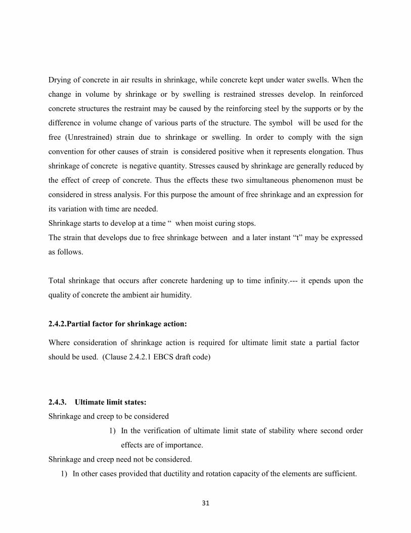
Example: Bars II and III are outside the section being considered: % = 50 and 6=1.4
Figure-3.4: Percentage of lapped bars in one lapped section
3.3.1.5. Transverse reinforcement in the lap zone:
1) Transverse reinforcement for bars in tension
2) Transverse reinforcement for bars permanently in compression.
Diameter of lapped bars or percentage of Transverse reinforcements bars in tension.

42
lapped bars in a section
1) or percentage of lapped bars Any transverse reinforcement or links
necessary for other reasons may be assumed
sufficient for the transverse tensile forces
without further justification.
2)
, The transverse bars should be placed
perpendicular to the direction of lapped
reinforcement
Transverse reinforcement total area(sum of all
legs parallel to the layer of the spliced
reinforcement)
- Area of one lapped bar
3) If more than 50% reinforcement is
lapped at one point and the distance
“a” between adjacent laps at a section is
Transverse reinforcement should be formed by
links or “U” bars anchored into the body of the
section.
Table-3.1. Transverse reinforcement in the lap zone.
Transverse reinforcement for bars permanently in compression.
In addition to the rules for bars in tension one bar of the transverse reinforcement should be
placed outside each end of the lap length and within 4 of the ends of the lap length.

43
(a) Bars in tension
(b) Bars in compression
Fig-3.5. Transverse reinforcement for lapped splices.
Laps for welded mesh fabrics made of ribbed wires
Laps of the main reinforcement:
1) Laps may be made by either by intermeshing or by layering of the fabrics.

44
(a).Intermeshed fabric (longitudinal section)
(b).Layered fabric (longitudinal section)
Fig-3.6.lapping of welded fabric.
2) Where fatigue loads occur intermeshing should be adopted
3) The percentage of the main reinforcement which may be lapped in any one section should
comply with the following
a) For intermeshed fabric the values of is sufficient which is given above.
b) For layered fabric the permissible percentage of the main reinforcement that
may be spliced by lapping in any section depends on the specific cross section
area of the welded fabric provided (S)Prov, where “s” is the spacing of wires.
45
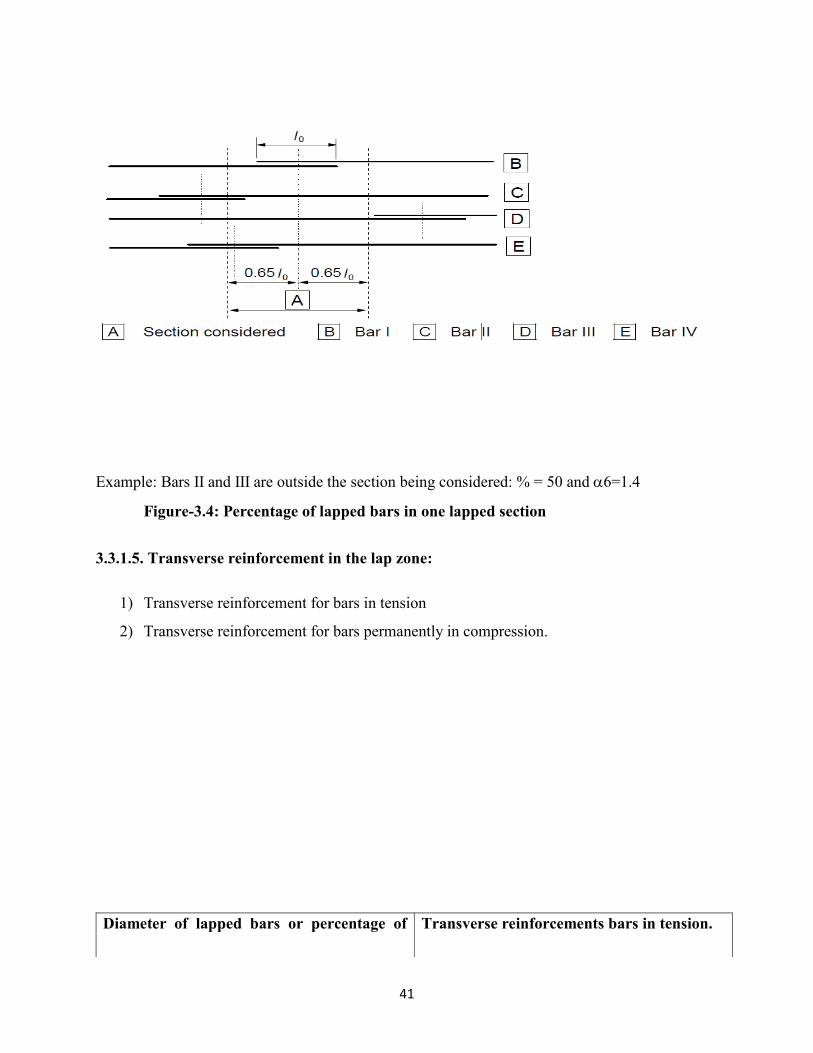
In the left hand case n1 = 1, n2 = 2 and in the right hand case n1 = 2, n2 = 2
Figure-3.7.Additional reinforcement in an anchorage for large diameter bars where there is
no transverse compression
3.4. Spacing of bars:
3.4.1. Clear distance:
The clear distance (horizontal and vertical) between individual parallel bars or horizontal layers
of parallel bars should not be less than the maximum of , bar diameter(,is the maximum size of
the aggregate(Clause 8.2)
from nation Annex- 1 and 5 respectively.
The spacing of bars shall be such that the concrete can placed and compacted satisfactorily for
the development of adequate bond.
3.4.2.Spacers and chairs: The subject is not addressed in the EBCS-2 and Ec-2
Spacers and chairs are used to have a suitable concrete cover or to hold bars position. They are
made of sundry Materials.
46
Spacers:
Mortar or galvanized or plastic or stainless steel wire elements designed to ensure a satisfactory
concrete cover for reinforcing bars.
Chairs:
These may be discrete to support bars in a specific position or continuous for continuous
supports. Chairs are usually made of galvanized or stainless steel wire.
Spacers are provided in slabs and footings for bottom reinforcement and for slab edges. On the
other hand chairs and continuous chairs and special chairs for top reinforcement in slabs and
footings.In beams spacers should be set in the stirrups at intervals of not more than 1000mm
longitudinally. In columns along the length spacers should be placed in the stirrups not more than
100 times the minimum dia. of main reinforcement. And in walls spacers should be staggered in
each layer of reinforcement at intervals measuring larger of 500mm or 50 times the dia. of the
reinforcing bars.
Clause 7.3 BS 8110:
This clause of the code recommendations are given to ensure that the reinforcement is properly
placed and the required cover is obtained. This is achieved during construction by inserting
spacer blocks and chairs in the formwork on the reinforcement.
The spacer must be designed such that they are durable and will not lead to corrosion of the
reinforcement or to palling of the concrete. The use of spacer blocks constructed on site from
concrete is not permitted.
3.5. Permissible mandrel diameters for bent bars:
Where normal hooks are used they should be of U-type or L-type but usually U- type is preferred
for mild steel bars and L-type for deformed bars. If the radius of the bend or hooks conforms to

47
that of the standard hooks or bends in longitudinal bars the bearing stresses inside the bend in
concrete need not be checked. Otherwise bearing stress must be checked by using the following
formula.
Bearing stress =
Tensile force due to design loads in a bar or group of bars(n)
Internal radius of the bend(mm) and
Size of the bar or if in bundle the size of bar of equivalent area (mm)
For limit state method of design this stress shall not exceed
Where is the characteristic strength of the concrete
for a particular bar or group of bars in contact shall be taken as a c/c distance between bars or
group of bars perpendicular to the plane of the bend (mm)for a bar or group of bars adjacent to
the face of the member, “a” shall be taken as the cover plus size of bar.
In other words the minimum radius of the bend “r” should be such that
Where
The minimum diameter to which a bar is bent shall be such as to avoid bending cracks in the bar,
and to avoid failure of concrete inside the bend of the bar and to avoid failure of concrete inside
the bend of the bar.
In order to void damage to the reinforcement the diameter to which the bar is bent(Mandrel
diameter) should not be less than
National Annex, below Table
a) For bars and wire
Bar diameter
Minimum mandrel diameter for
bends, hook and loops (see Figure 8.1)

48
≤ 16 mm 4
> 16 mm 7
b) For welded reinforcement and mesh bent after welding
Minimum mandrel diameter
5ø
d≥3ø : 5ϕ
d<3ø or welding within the curved zone:
20ø
Note: The mandrel size for welding within the curved zone may be reduced to 5ø
where the welding is carried out in accordance with EN ISO 17660
Table-3.2: Minimum mandrel diameter to avoid damage to reinforcement
The mandrel diameter need not be checked to avoid concrete failure if the following conditions
exist:
i) either the anchorage of the bar does not require a length more than 5 past the end of
the bend or

49
ii) Thebar is not positioned at the edge (plane of bend close to concrete face) and there is
a cross bar diameter ≥ inside the bend.”.
iii) The mandrel diameter is at least equal to the recommended values given in Table.
Otherwise the mandrel diameter,,should be increased in accordance with below
Expression
Where:
is the tensile force from ultimate loads in a bar or group of bars in contact at the start of a bend
for a given bar (or group of bars in contact) is half of the Centre-to-Centre distance between bars
(or groups of bars) perpendicular to the plane of the bend. For a bar or group of bars adjacent to
the face of the member,should be taken as the cover plus / 2.The value of should not be taken
greater than that for concrete class C55/67.
3.6. Anchorage of longitudinal reinforcement:
3.6.1. Reinforcing bars, wires or welded mesh fabrics: Reinforcing bars, wires or welded
mesh fabrics shall be so anchored that the bond forces are safely transmitted to the concrete
avoiding longitudinal cracking or sapling. Transverse reinforcement shall be provided if
necessary.

50
a) Basic tension anchorage length lb,rqd, b)Equivalent anchorage length for
standard for any shape measured along bend
the center line
c)Equivalent anchorage d) Equivalent anchorage e) Equivalent length
length for standard hook length for standard loop for welded transverse bar
Fig-3.8.Basic anchorage length
(1) The calculation of the required anchorage length shall take into consideration the type of steel
and bond properties of the bars.
(2) The basic required anchorage length, for anchoring the force, in a straight bar assuming
constant bond stress equal to follows from:
Where is the design stress of the bar at the position from where the anchorage is measured from.
Values for are given.
(3) For bent bars the basic required anchorage length, and the design length, , should be
measured along the centre-line of the bar
(4) Where pairs of wires/bars form welded fabrics the diameter,, in the above Expression should
be replaced by the equivalent diameter
51
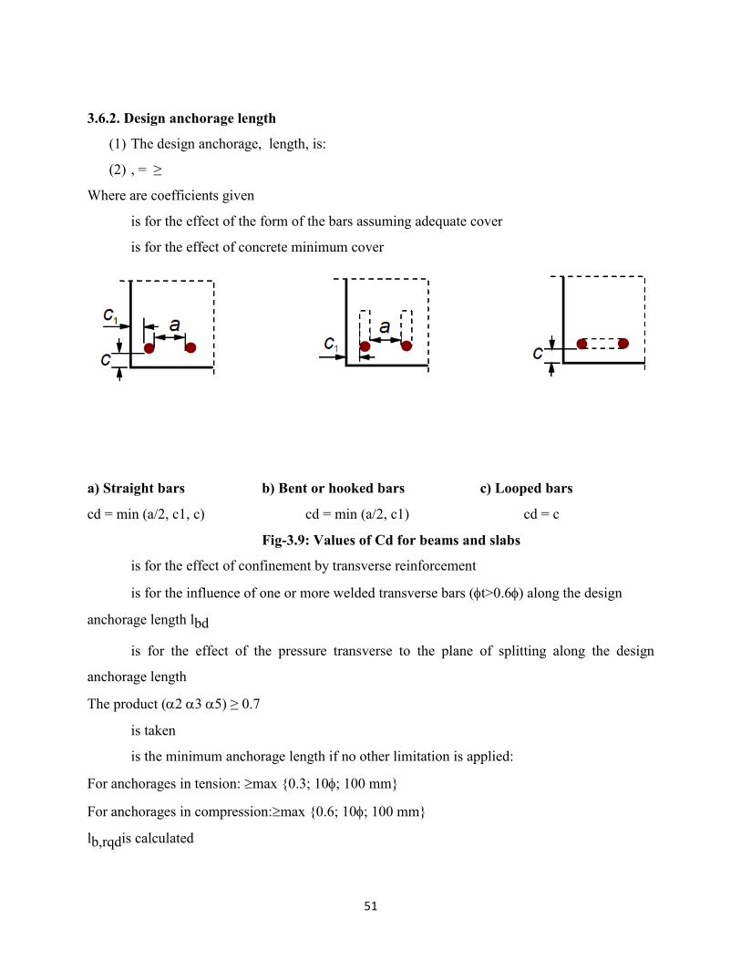
3.6.2. Design anchorage length
(1) The design anchorage, length, is:
(2) , = ≥
Where are coefficients given
is for the effect of the form of the bars assuming adequate cover
is for the effect of concrete minimum cover
a) Straight bars b) Bent or hooked bars c) Looped bars
cd = min (a/2, c1, c) cd = min (a/2, c1) cd = c
Fig-3.9: Values of Cd for beams and slabs
is for the effect of confinement by transverse reinforcement
is for the influence of one or more welded transverse bars (t>0.6) along the design
anchorage length lbd
is for the effect of the pressure transverse to the plane of splitting along the design
anchorage length
The product (2 3 5) ≥ 0.7
is taken
is the minimum anchorage length if no other limitation is applied:
For anchorages in tension: max {0.3; 10; 100 mm}
For anchorages in compression:max {0.6; 10; 100 mm}
lb,rqdis calculated

52
Influencing factor Type of anchorage
Reinforcement bar
In tensionIn
compression
Shape of bars
Straight = 1.0 1.0
Other than straight (see
Figure 8.1 (b), (c) and (d) of
EBCS-1)
= 0.7 if > 3
Otherwise = 1.0
(see above Figure for values
of )
= 1.0
Concrete cover
Straight = 1 – 0.15 ( - )/
≥ 0.7
≤ 1.0
= 1.0
Other than straight (see
Figure 8.1 (b), (c) and (d) of
EBCS-1)
= 1 – 0.15 ( - 3)/
≥ 0.7
≤ 1.0
(see above Figure for values
of )
= 1.0
Confinement by transverse
reinforcement not welded to
main reinforcementAll types
= 1 – K
≥ 0.7
≤ 1.0
= 1.0
Confinement by welded
transverse reinforcement*
All types, position and size
as specified in Figure 8.1 (e)
of EBCS-1)
= 0.7 = 0.7
Confinement All types = 1 – 0.04p -

53
by transverse pressure ≥ 0.7
≤ 1.0
where:
λ = ( - )/
cross-sectional area of the transverse reinforcement along the design anchorage length
cross-sectional area of the minimum transverse reinforcement
= 0.25 As for beams and 0 for slabs
area of a single anchored bar with maximum bar diameter
K values shown in below Figure
p transverse pressure [MPa] at ultimate limit state along
For direct supports may be taken less than provided that there is at least one transverse wire welded within the
support. This should be at least 15 mm from the face of the support.
Table-3.3: Values of
Fig- 3.10. Values of K for beams and slabs
3.6.3 Anchorage of links and shear reinforcement
(1) The anchorage of links and shear reinforcement should normally be effected by means of
bends and hooks, or by welded transverse reinforcement. A bar should be provided inside
a hook or bend.
(2) The anchorage should comply with belowFigures. Welding should be carried out in
accordance with EN ISO 17660
Note: For definition of the bend angles see Figure3.11

54
Fig 3.11-Anchorage of links
Anchorage by welded bars
Additional anchorage to that of the above may be obtained by transverse welded bars (see Figure
3.12) bearing on the concrete. The quality of the welded joints should be shown to be adequate
Fig-3.12. Welded transverse bar as anchoring device
(2) The anchorage capacity of one welded transverse bar (diameter 14 mm - 32 mm), welded
on the inside of the main bar, is may then be reduced by /, where , is the area of the bar.
Note: The recommended value of is determined from:
= but not greater than

55
Where:
is the design shear strength of weld (specified as a factor times; say 0.5 where is the
cross-section of the anchored bar and fyd is its design yield strength)
-- is the design length of transverse bar: ltd = 1.16 t(fyd/σtd)0.5 ≤ lt
-- is the length of transverse bar, but not more than the spacing of bars to be anchored
is the diameter of transverse bar
is the concrete stress; σtd = (fctd + σcm)/y ≤ 3 fcd
is the compression in the concrete perpendicular to both bars (mean value, positive for
compression)
y is a function: y = 0.015 + 0.14 e(-0.18x)
x is a function accounting for the geometry: x = 2 () + 1
c is the concrete cover perpendicular to both bars
Anchorage by BS 8110:
In many instances there is insufficient length available to incorporate an additional straight length
bar and an alternative such as bend or a hook is used.
The most common locations for bends is at the simply supported ends of member where an
effective anchorage length beyond the center line of the support equivalent to (12 * bar diameter)
is required.
The effective anchorage length of a bend or hook is defined in Clause 3.12.8.23 as the greater of
1) 4r, where “r” internal radius of bend, 12 * bar diameter or the actual length of the bar ( r-
is equal to 3d in a standard hook or bend) for bends.
2) 8r, where “r” is the internal radius of the bend , 24* bar diameter or the actual length of
bar( r- is normally assumed to be equal to “3d” in a standard hook or bend) for hooks
In addition any length of bar in excess of (4 * bar diameter) beyond the end of bend and which
lies within the concrete in which the bar is to be anchored may also be included for effective
anchorage.

56
lbdb
llllbd
b
a) Direct support: Beam supported by b) Indirect support: Beam intersecting
wall or column another supporting beam
Anchorage length is measured from the line of contact between beam and support
Fig-3.13.Anchorage of bottom reinforcement at end supports
Where a beam is supported by a beam instead of wall or column reinforcement is provided and
designed to resist the mutual reaction. The supporting reinforcement is in addition to that
required for other reasons. The supporting reinforcement between two beams should consist of
links surrounding the principal reinforcement of the supporting member. The supporting links
may be placed in a zone beyond the intersection of beams.
Mechanical anchorages:
When length available for anchorage is small mechanical anchorages in the form of welded cross
bars or end plates may be used. It is common in precast elements, corbels, brackets and at other
support points.
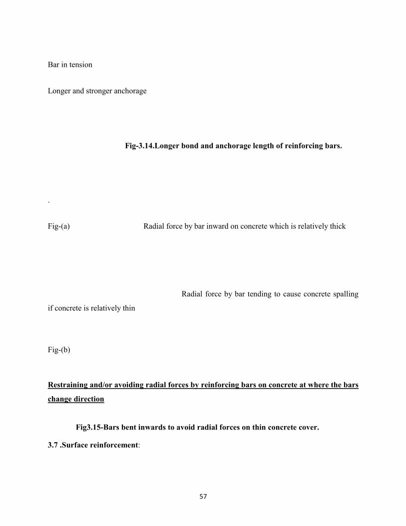
Longer and stronger anchorage length of reinforcing bars in concrete to ensure failure by yielding
prior to bond slippage as the latter failure is more brittle.
Ensure failure by yielding here instead of bond failure behind
57
Bar in tension
Longer and stronger anchorage
Fig-3.14.Longer bond and anchorage length of reinforcing bars.
.
Fig-(a) Radial force by bar inward on concrete which is relatively thick
Radial force by bar tending to cause concrete spalling
if concrete is relatively thin
Fig-(b)
Restraining and/or avoiding radial forces by reinforcing bars on concrete at where the bars
change direction
Fig3.15-Bars bent inwards to avoid radial forces on thin concrete cover.
3.7 .Surface reinforcement:

58
It may be necessary to provide surface reinforcement either to control cracking or to ensure
adequate resistance to spalling of the cover.
Surface reinforcement to resist palling should be used where:
i) bars with diameter greater than 32 mm or
ii) bundled bars with equivalent diameter greater than 32 mm
The surface reinforcement should consist of wire mesh or small diameter bars, and be placed
outside the links.
The area of surface reinforcement
>0.01 - in the direction perpendicular to large dia bars.
>0.02 -parallel to those bars.
Where the cover to reinforcement is greater than 70 mm, for enhanced durability similar surface
reinforcement should be used, with an area of 0,005 Act,extin each direction.
The longitudinal bars of the surface reinforcement may be taken into account as longitudinal
bending reinforcement and the transverse bars as shear reinforcement provided that they meet the
requirements for the arrangement and anchorage of these types of reinforcement
3.8. Bundled bars:
A bundle is defined as a group of parallel bars bundled in contact to act as unit. Not more than
four bars can be grouped into one bundle.
Bundled bars can be used as column verticals.
In Beams When bars are placed in contact with each other in groups of 2, 3 or 4 as bundled bars.
The minimumclear space provided between bundles for buildings under ACI 318(7.6.3) shall be
equal to the diameter of a single round bar having an area equivalent to the area of the bundle.
Unless otherwise stated the rules for individual bars apply to bundles of bars.

59
In a bundle all bars should of the same characteristics (type and grade)
Bars of different sizes may be bundled provided that the ratio of diameters does not exceed 1.7
In design the bundle is replaced by a notional bar having the same sectional area and the same
center of gravity as the bundle. The equivalent diameters of this notional bar is such that.
is number of bars in bundle which is limited to for vertical bars in compression and for bars in a
lapped joint.
for all other cases.
For a bundle the rules given above for individual bars apply for spacing.
The equivalent diameter “ should be used, but the clear distance between bundles should be
measured from the actual external contour of the bundle bars.
The concrete cover should be measured from the actual external contour of the bundles and
should not be less than
Where two touching bars are positioned one above the other and where the bond conditions are
good such bars need to be treated as a bundle.
Anchorage of bundles of bars:
Bundles of bars in tension may be curtailed over end and intermediate supports.
Equivalent diameter of bar < 32 mm May be curtailed near a support without the need for
staggering bars
Equivalent diameter of bar mm .Which are anchored near a support, should be staggered in the
longitudinal direction.
Where individual bars are anchored with a staggered distance greater than (Where based on the
bar diameter) the diameter of the bar may be used in assessing .Otherwise the equivalent
diameter of the bundle should be used.

60
Fig-3.16: Anchorage of widely staggered bars in a bundle
For compression anchorages bundled bars need not be staggered.
For bundles with an equivalent dia. mm.At least four links having a diameter should be provided
at the ends of the bundle .A further link should be provided just beyond the end of the curtailed
bar.
Lapping bundles of bars:
The lap length should be calculated in accordance with the following formula using as the
equivalent diameter of bar.
For bundles which consist of two bars
With an equivalent diameter is < 32 mm.The bars may be lapped without staggering individual
bars. In this case equivalent bar size is used to calculate
For bundles which consist of two bars with
An equivalent diameter or of 3 bars.Individual bars should be staggered in the longitudinal
direction by at least 1.3

61
(Where is based on single bar)
Care should be taken to ensure that there are not more than four bars in any lap cross section
Bundles of more than 3-bars should not be lapped.
3.9. Concrete cover
Concrete cover is defined as it is the distance between surface of the reinforcement closest to the
nearest concrete surface (including links and stirrups and surface reinforcement where relevant
and the nearest concrete surface) (clause 4.4.1.1(1)).
The nominal cover shall be specified on the drawings it is defined as minimum cover plus an
allowance in design for deviation (clause 4.4.1.1(2))
Minimum cover:-
Minimum concrete cover - shall be provided in order to ensure
i) The safe transmission of bond forces
ii) The protection of the steel against corrosion(durability)
iii) An adequate fire resistance
The greater value for “ satisfying the requirements for both bond and environmental conditions
shall be used.
Where
cmin,b -- minimum cover due to bond requirement,
cmin,dur -- minimum cover due to environmental conditions,
Δcdur, --additive safety element,

62
Δcdur,st -- reduction of minimum cover for use of stainless steel,
Δcdur,add--reduction of minimum cover for use of additional protection,
In order to transmit bond forces safely and to ensure adequate compaction of the concrete the
minimum cover should not be less than cmin,b. (Clause 4.4.1.2(3))
Bond Requirement
Arrangement of
bars Minimum cover cmin,b*
Separated Diameter of bar
Bundled Equivalent diameter (n)
*: If the nominal maximum aggregate size is greater than 32 mm, Cmin,b,
should be increased by 5 mm.
Table-3.4. minimum cover C min, b- requirements with regard to bond:
Structural Class

63
Criteria
Exposure Class according to Table 4.1
X0 XC1 XC2 /
XC3
XC4 XD1 XD2/
XS1
XD3/
XS2/
XS3
Design working life
of 100 years
Increase
class by 2
Increase
class by 2
Increase
class by 2
Increase
class by 2
Increase
class by 2
Increase
class by 2
Increase
class by 2
Strength Class1)2)
C30/37
reduce
class by 1
C30/37
reduce
class by 1
C35/45
reduce
class by 1
C40/50
reduce
class by 1
C40/50
reduce
class by 1
C40/50
reduce
class by 1
C45/55
reduce
class by 1
Member with slab
geometry
(Position of
reinforcement not
affected by
construction process)
reduce
class by 1
reduce
class by 1
reduce
class by 1
reduce
class by 1
reduce
class by 1
reduce
class by 1
reduce
class by 1
Special Quality
Control of the
concrete production
ensured
reduce
class by 1
reduce
class by 1
reduce
class by 1
reduce
class by 1
reduce
class by 1
reduce
class by 1
reduce
class by 1
Values of minimum cover cmin,durrequirements with regard to durability for reinforcement steel
in accordance with EN10080.
Table-3.5.Recommended structural classification:
64
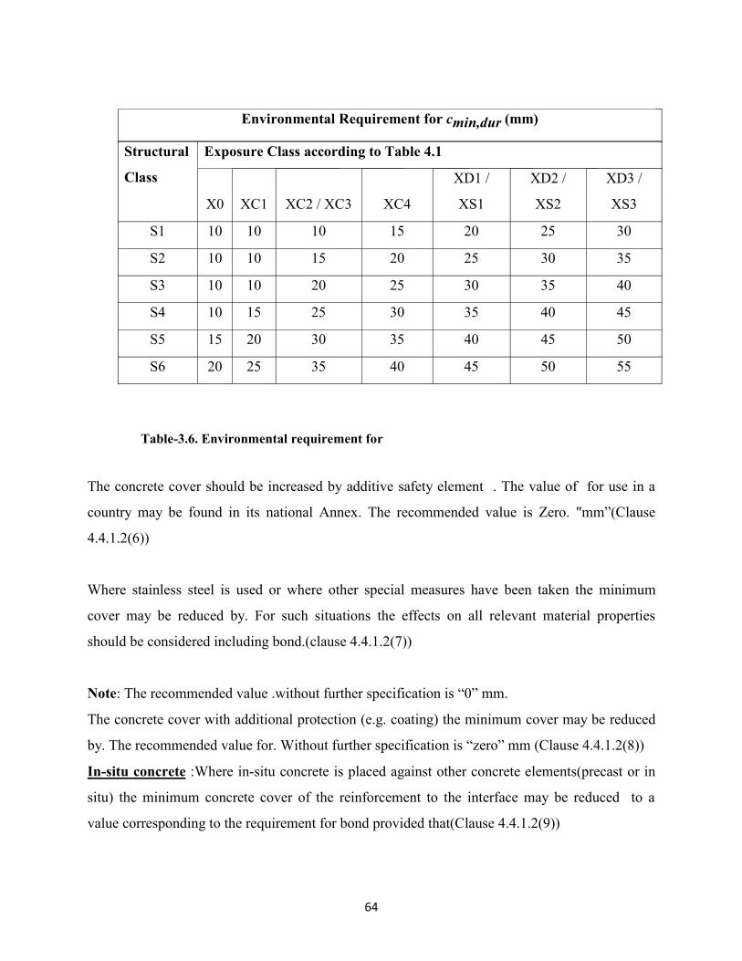
Environmental Requirement for cmin,dur (mm)
Structural
Class
Exposure Class according to Table 4.1
X0 XC1 XC2 / XC3 XC4
XD1 /
XS1
XD2 /
XS2
XD3 /
XS3
S1 10 10 10 15 20 25 30
S2 10 10 15 20 25 30 35
S3 10 10 20 25 30 35 40
S4 10 15 25 30 35 40 45
S5 15 20 30 35 40 45 50
S6 20 25 35 40 45 50 55
Table-3.6. Environmental requirement for
The concrete cover should be increased by additive safety element . The value of for use in a
country may be found in its national Annex. The recommended value is Zero. "mm”(Clause
4.4.1.2(6))
Where stainless steel is used or where other special measures have been taken the minimum
cover may be reduced by. For such situations the effects on all relevant material properties
should be considered including bond.(clause 4.4.1.2(7))
Note: The recommended value .without further specification is “0” mm.
The concrete cover with additional protection (e.g. coating) the minimum cover may be reduced
by. The recommended value for. Without further specification is “zero” mm (Clause 4.4.1.2(8))
In-situ concrete :Where in-situ concrete is placed against other concrete elements(precast or in
situ) the minimum concrete cover of the reinforcement to the interface may be reduced to a
value corresponding to the requirement for bond provided that(Clause 4.4.1.2(9))

65
i) The strength class of concrete is at least
ii) The exposure time of the concrete surface to an outdoor environment is short(< 28
days)
iii) The interface has roughened.
Allowance in design for deviation:
To calculate the nominal cover an addition to the minimum cover shall be made in design to
allow for the deviation (.The required minimum cover shall be increased by the absolute value of
the accepted negative deviation.(clause 4.4.1.3)
The value of for use in a country may be found in its national annex. The recommended value is
10 mm.
Nominal cover
(Specified in R.C drawing)
Minimum cover
(Durability and Bond)
Allowance for deviation
Axis distance, “a”
(Fire Protection)
Fig-3.17. For Specification of cover to reinforcement

66
Nominal cover (IS-456-2000):
It is the dimension used in design and drawings .It shall not be less than the diameter of the bar.
For a longitudinal reinforcing bar in compression in a column nominal cover shall in any case not
be less than 40mm or less than the diameter of such bar. In the case of columns of minimum
dimension of 200 mm or under whose reinforcing bars do not exceed 12 mm a nominal cover of
25 mm may be used.
For footings minimum cover shall be 50 mm
Clause 2.2.4 and 3.1.5 of BS 8110:
The integrity of the reinforced concrete depends on its ability to prevent corrosion of the
reinforcement when exposed to a wide range of environmental conditions. In addition to
protection against corrosion of the steel, fire resistance requirements are also necessary to allow
sufficient time to evacuate a building an prevent premature failure, spalling of the concrete must
be avoided and adequate bond forces must develop between the reinforcement and concrete.
The essential elements of design which ensure adequate durability are the structural form/
detailing and the amount of concrete cover provided to protect the steel.
The actual concrete cover provided varies due to a number of factors such as:
1) Construction tolerances inherent in buildings the formwork(i.e., the mould into which the
concrete is cast)
2) Variations in dimensions of the reinforcement resulting from the cutting bending of the
steel and
3) Errors occurring during the fixing of the steel in the formwork.
There area number of criteria to be considered when determining the nominal cover. They are
1) Bar size: (Clause 3.3.1.2 BS 8110):
a) Single bar: nominal cover main bar diameter

67
b) Paired bars: nominal cover main bar
c) Bundled bars: nominal cover
Where is the cross sectional area equal to the sum of the cross sectional area of the
bars in bundle, for example if 4 bars in bundle , where “d” diameter of one bar.
2) Nominal maximum aggregate size: (Clause 3.3.1.3 of BS 8110):
Nominal cover nominal maximum size of aggregate i.e, normally
In most cases 20 mm size aggregate is suitable.
3) Uneven surfaces (Clause 3.3.1.4 BS 8110):
When concrete is cast on uneven surfaces (e.g., earth or blinding which is finely crushed
aggregate rolled on the top of compacted fill such as Hard core ) additional cover
specified to that indicated by this code should be provide as shown below.
Concrete
Concrete Nominal cover
Uneven earth surface
Fig-3.18 Concrete cast directly on the earth – nominal cover from average soil
level
Concrete
Concrete Nominal cover
Blinding layer
Hard Core
Fig- 3.19 Concrete cast on an adequate blinding layer(e. g: 50 mm thick)

68
For uneven surfaces :( e.g. exposed aggregate) the minimum cover should be increased by at
least 5mm.(EBCS clause 4.4.1.2(11))
4) Ends of straight bars (Clause 3.3.2 BS 8110)
Normally 40 mm cover is provided at the ends of straight bars , however as indicated in
this clause where the end of a floor or roof unit is not exposed to the weather r to
condensation cover is not mandatory.
Minimum dimensions (Clause 3.3.36 of BS 8110):
In addition to nominal cover requirements the code also specifies minimum dimensions (i.e,
beam widths, rib widths, floor and wall thicknesses and column widths) for some structural
elements to provide adequate fire resistance. The dimensions are given to ensure minimum
periods of fire resistance ranging from 0.5 hours to 4 hours and elate specifically to the covers
given in the BS 8110 Table 3.4.

69
Chapter-4
Structural Elements
4.1. BEAMSCriteria EBCS-2,Final
Draft
EC-2, values BS 8110,values IS 456-2000
Main Reinforcement:
Minimum area of
main bars in tension
C l a u s e
9.2.1.1(1) 0.26
0.26
0.0013bh
Maximum area of
t e n s i o n
reinforcement
C l a u s e
9.2.1.1(3)
0.04
0.04 bd 0.04 bh 0.04bD
Main bars in
compression
-------- ----------- 0.002bh 0.04bD
Spacing of main
bars,
--------
Links
Minimum area of ----------- 0.4bs/0.87

70
shear reinforcement
Spacing --------- 0.75d 0.75d 0.75d for
vertical stirrups
and “d” for
i n c l i n e d
stirrups.
---------- 0.75d d or 150mm
from main bar
Shall not be
greater than 300
mm
Table 4.1. Beam values
4.2. Other code provisions:
IS 456 -2000:
Where the maximum shear stress calculated is less than half the permissible value and in
members of minor structural importance such as lintels this provision (minimum shear
reinforcement) need not be complied with.
Clause 26.5.1.3(IS 456-2000):
Apart the specified reinforcement in the table if the depth of the web in a beam exceeds 750 mm
side face reinforcement shall be provided along the two faces. The total area of such
reinforcement shall be not less than 0.1% of the web area and shall be distributed equally on two
faces at a spacing not exceeding 300 mm or web thickness whichever is less.
Clause 3.12.5.4 BS 8110:
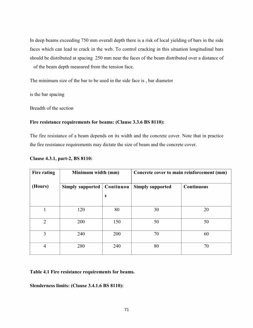
71
In deep beams exceeding 750 mm overall depth there is a risk of local yielding of bars in the side
faces which can lead to crack in the web. To control cracking in this situation longitudinal bars
should be distributed at spacing 250 mm near the faces of the beam distributed over a distance of
of the beam depth measured from the tension face.
The minimum size of the bar to be used in the side face is , bar diameter
is the bar spacing
Breadth of the section
Fire resistance requirements for beams: (Clause 3.3.6 BS 8110):
The fire resistance of a beam depends on its width and the concrete cover. Note that in practice
the fire resistance requirements may dictate the size of beam and the concrete cover.
Clause 4.3.1, part-2, BS 8110:
Fire rating
(Hours)
Minimum width (mm) Concrete cover to main reinforcement (mm)
Simply supported Continuou
s
Simply supported Continuous
1 120 80 30 20
2 200 150 50 50
3 240 200 70 60
4 280 240 80 70
Table 4.1 Fire resistance requirements for beams.
Slenderness limits: (Clause 3.4.1.6 BS 8110):

72
To guard against lateral buckling the slenderness limits should not be exceeded as given below
table. The term slenderness limit is defined as the clear distance between lateral restraints “d” is
the effective depth and “ the breadth of the compression face of the beam midway between
restraints.
Slenderness limits:
Type of beam Slenderness limits
Simply supported
Continuous Same as above
Cantilever
Table 4.2. Slenderness limit for beams
4.3. EBCS provisions:
4.3.1. Elements of the structure :( clause 5.3.1)
1) The elements of a structure are classified, by consideration of their nature and function, as
beams, columns, slabs, walls, plates, arches, shells etc. Rules are provided for the
analysis of the commoner of these elements and of structures consisting of combinations
of these elements.
2) A beam is a member for which the span is not less than 3 times the overall section depth.
Otherwise it should be considered as a deep beam
4.3.2. Reinforcement:

73
4.3.2.1. Minimum reinforcement
Minimum areas of reinforcement are given in order to prevent brittle failure, wide cracks and
also to resist forces arising from restrained actions.
The area of longitudinal tension reinforcement should not be taken as less than
Where denotes the mean width of tension zone,
For a T-beam with the flange in only the width of the web is taken into account in calculating the
value of
Should be determined with respect to the relevant strength class (given in table 3.1 of EBCS-2)
Alternatively for secondary elements where some risk of brittle failure may be accepted may be
taken as 1.2 times the area required in ULS verification.
Sections containing less reinforcement than, should be considered as unreinforced.
The cross sectional area of tension or compression reinforcement should not exceed outside lap
locations.
S t r e n g t h
class
C C16/
20
C20/
25
C25/
30
C30/
35
C35/
45
C40/
45
C45/
50
C50/
60
C28/
35
C32/
40
0.130 0.130 0.130 0.135 0.151 0.166 0.182 0.198 0.213 0.146 0.156
Table-4.3. Minimum percentage of steel
4.3.2.2. Design of supports:
In monolithic construction even when simple supports have been assumed in design the section
at supports should be designed for a bending moment arising from partial fixity of at least of the
maximum bending moment in span.
for beams= 0.15(National Annex)

74
4.3.3. GEOMETRIC DATA
4.3.3.1 .Effective spans of beams and slabs in building (Clause 5.3.2.2)
The effective span, leff of a member should be calculated as follows:
Where:
ln is the clear distance between the faces of the supports;
Values for a1 and a2, at each end of the span, may be determined from the appropriate ai values
in Figure given below where”t“is the width of the supporting element as shown.
a) Non continuous members b) Continuous members

75
a) Supports considered fully restrained d) Bearing provided
e) Cantilever
Fig- 4.0.Effective span for different support conditions.
No restraint to rotation support:
i) Assumption: Continues slabs and beams may generally be analyzed that the supports
provide no rotational restraint.(e.g., over walls).
76
ii) A beam or slab is continuous over this type of support, the design support moment,
calculated on the basis of a span equal to the centre-to centre distance between
supports, may be reduced by an amount as follows:
-
t- is the breadth of the support
Note: Where support bearings are used t should be taken as the bearing width
Monolithic support for beam or slab:
i) For this condition the critical design moment at the support should be taken at the
face of the support
ii) The design moment and reaction transferred to the supporting element (e.g. column,
wall etc.) should be generally taken greater of the elastic or redistributed values.
Note: The moment at the face of the support should not be less than 0.65 that of the full fixed
end moment.
4.3.3.2. Effective width of flanges (for all limit states)
1) The effective width of flange should be based on the length between points of aero moment,
which may be obtained from the below figure.

77
Fig-4.1: Definition of”, for calculation of effective flange width
Note: The length of the cantilever, l3, should be less than half the adjacent span and the
ratio of adjacent spans should lie between 2/3 and 1.5.
2) In T beams the effective flange width, over which uniform conditions of stress can be
assumed, which depends on the web and flange dimensions, the type of loading, the span,
the support conditions and the transverse reinforcement
3) The effective flange width beff for a T beam of L beam maybe derived as:
Where
and

78
Fig-4.2 Effective flange width parameters
4.3.4. Transverse Reinforcement:
Transverse reinforcement in concrete with stronger anchorage by means of hooks with bent
angles for ensuring better performance of the transverse reinforcements.
Comparison of anchorage between bend and
i) The end of the bend is anchored into the interior of the concrete member and thus
risk of “opening up” is reduced.
ii) bend can easily open up and spall the concrete cover under tensile load

79
a) b)
Fig-4.3, Transverse reinforcement anchorage bends
As discussed by Law and Mak (2013) though the hook is unarguably better option, the hook is
more popular as it has the relative ease of placement. The hook is much more difficult to place
especially when the cast in bars are misaligned. However if there are other physical restraints
such as adjoining beams or slabs preventing the opening up of the hook, the use of the hook
should be acceptable.
Stirrup anchorage: (As3600-2009- Clause 8.2.12.3)
Stirrup anchorages should be located in the compression zone and be shown on structural
drawings.
The area of shear reinforcement required at a particular cross section should be provided for a
distance “D” from that cross section in the direction of decreasing shear
4.4. T-Beams:
4.4.1. Placing of tension reinforcement in flanged cross section:
Fig-4.4.Distribution of tension reinforcement in flanged cross section

80
Tension reinforcement in a flanged beam at supports should be spread over the effective width.
Any compression longitudinal reinforcement (diameter which is included in the resistance
calculation should be held by transverse reinforcement with spacing not greater than “15.”
Reinforcement in flanges of T and L beams (IS 26.5.1.8)
Where the flanges in tension a part of the main reinforcement shall be distributed over the
effective flange width or a width equal to one tenth of the span. Whichever is smaller. If the
effective flange width exceeds one tenth of the span nominal longitudinal reinforcement shall be
provided in the outer portions of the flange.
4.4.2. Curtailment of longitudinal reinforcement:
Sufficient reinforcement should be provided at all sections to resist the envelope of the acting
tensile force, including the effect of inclined cracks in webs and flanges. For members with shear
reinforcement the additional tensile force should be calculated by
hereis the maximum moment along the beam.
-Applied shear force
Angle between shear reinforcement and beam axis
Angle between the concrete compression strut and the beam axis.
Inner lever arm –in the shear analysis of reinforced concrete without axial force the

81
approximate value may normally be used
For members without shear reinforcement may be estimated by shifting the moment curve a
distance
The “shift rule “may also be used as an alternative for members with shear reinforcement where
Curtailment of tension reinforcement in flexural members (IS 456-2000)
For curtailment reinforcement shall extend beyond the point at which it is no longer required to
resist flexure for a distance equal to the effective depth of the member or 12 times the bar
diameter which ever greater except at simple support or end of cantilever.
Note: a point at which reinforcement is no longer required to resist flexure is where the resistance
moment of the section considering only the continuing bars is equal to the design moment
Curtailment of bundled bars: (IS456-2000, clause-26.2.3.5)
Bars in bundle shall terminate at different points spaced apart by not less than 40 times the bar
diameter except for bundles stopping at a support.
Positive moment reinforcement (IS 456-2000, Clause- 26.2.3.3)
At least one third the positive moment reinforcement in simple members and one fourth the
positive reinforcement in continuous members shall extend along the same face of the members
into the support to a length equal to
82
Negative moment reinforcement:
At least one third of the total reinforcement provided for negative moment at the support shall
extend beyond the point of inflection for a distance not less than the effective depth of the
member of or of the clear span whichever is greater.
4.4.3. Anchorage of bottom reinforcement:
The anchorage length of a bent up bar which contributes to the resistance to shear should be not
less than in the tension zone and in the compression zone , it is measured from the point of
intersection of the axes of the bent up bar and the longitudinal reinforcement.
4.4.3.1. At end supports with little or no end fixity:
bottom steel at support provided in the span (National Annex),is required from the line of
contact at the support.
In case of simple support, the support conditions are may be direct or indirect. Direct support is
such when beam is supported by wall or column and indirect support is when beam intersecting
another supporting beam. In case of direct support transverse pressure may only be taken into
account.
On the other hand indirect support, where a beam is supported by a beam instead of wall or
column, reinforcement should be provided and designed to resist the mutual reaction .The
supporting reinforcement is in addition to that required for other reasons. The supporting
reinforcement between two beams should consist links surrounding the principal reinforcement
of the supporting member. The supporting links may be placed in a zone beyond the intersection
of beams.
4.4.3.2. Anchorage of bottom reinforcement at intermediate supports:

83
1) The anchorage length > 10(for straight bars) or diameter of mandrel (for hooks and bends
with bar diameters at least equal to 16mm) or twice the diameter of the mandrel(in other
cases.) (Figure(a))
2) The reinforcement required to resist possible positive moments (e.g. settlement of the
support, explosion, etc.).This reinforcement should be continuous which may be achieved by
means of lapped bars (see Figure (b) or (c)).
(a) (b) (c)
4.5. Anchorage at intermediate supports
Bends and hooks (IS-456-2000)

84
The anchorage value of the bend shall be taken as 4 times the diameter of the bar for each bend
subject to a maximum of 16 times the diameter of the bar.
The anchorage value of a standard “U-type” hook shall be equal to 16 times the bar dia.
Mechanical devices for anchoraging:
Any mechanical or other device capable of developing the strength of the bar without damage to
concrete may be used as anchorage with the approval of the engineer in charge.
Anchoraging bars in compression (IS-456-2000)
The anchorage length of straight bar in compression shall be equal to the development length of
the bars in the compression as
Nominal diameter of the bar
Stress in bar at the section considered at design load and
Design bond stress.
Development in compression (IS-456-2000):
The projected length of hooks, bends and straight lengths beyond bends if provided for a bar in
compression shall only considered for development length
Development length in Tension:
The development length includes anchorage values of hooks in tension reinforcement
Anchoraging shear reinforcement (IS 456-2000):

85
A) Inclined bars:- The development length shall be as for bars in tension , this length shall be
measured under
1) In tension zone rom the end of the sloping or inclined portion of the bar and
2) In the compression zone from the mid depth of the section
B) Stirrups:- In case of secondary reinforcement – such as stirrups and transverse ties ,
complete development lengths and anchorage shall be deemed to have been provided
when the bar is bent through an angle of at least round a bar of at least it’s own diameter
and is continued beyond the end of the curve for a length of at least eight diameter or
When the bar is bent through the angle of and is continued beyond the end of the curve
for a length at least six bar diameters or when the bar is bent through an angel of and is
continued beyond the end of the curve for a length of at least four diameters.
Simplified rules for curtailment of bars: (Clause 3.12.10.2 BS 8110):
In practical design bending moment diagram are often not drawn for members of secondary
importance and the theoretical cutoff points are not then known without further calculation. BS
8110 permits the simplified rules to be applied where beam supports substantially uniformly
distributed loads. In these rules “ refers to the effective span length and the bar size.
Simply supported beams: All the tension bars should be extended to within of the centers of the
supports. At least 50% of these bars should further extend for at least ( or its equivalent in hooks
or bends ) beyond centers of supports.
Cantilevers: All the tension bars at the support should extend a distance of whichever is greater.At least 50% of these bars should extend to the end of the cantilever.
Continuous beams of approximately equal spans:

86
1) All the tension bars at the support should extend from the face of the support, whichever
is greater. At least 60% of these bars should extend and at least 20% should continue
through the spans
2) All the tension bars at mid span should extend to within o.15l of interior supports and
0.1l of the exterior supports. At least 30% of these bars should extend to the centerof the
supports.
4.4.4. Simplified detailing rules for beams:
a) Continuous member top reinforcement
Reinforcement for maximum hogging moment
100%
60%
b) Continuous member bottom reinforcement
30%
100%
Position of effective support Reinforcement for maximum sagging moment
c) Simplesupport bottom reinforcement

87
25%
Position of effective support100%
Where, effective length
is the distance to allow for tensile force due to shear force
-design anchorage length,
:Minimum of two spans required, Applies to U.D.L only for above fig.’s
Fig-4.6. Curtailment of reinforcement for various supports
4.5. Shear reinforcement:-
The shear reinforcement should form an angle “of between 450 and 900 to the longitudinal axis
of the structural element.
The shear reinforcement may consists combination of
1) Links enclosing the longitudinal tension reinforcement and the compression zone
2) Bent up bars
3) Cages, ladders etc. which are cast in without enclosing the longitudinal reinforcement
but are properly anchored in the compression and tension zones.
At least of the necessary shear reinforcement should be in the form of links.(National Annex)

88
Inner link alternatives
--Enclosing link
Fig-4.7.Shear reinforcement
The ratio of shear reinforcementshear reinforcement ratio >
Area of shear reinforcement within length “s”
s- is the spacing of shear reinforcement measured along the longitudinal axis of the member.
bredth of the web of the member
angle between shear reinforcement and the longitudinal axis
For beams=
The maximum longitudinal spacing between shear assemblies <;
The maximum spacing of bent up bars <;
The transverse spacing of the legs in a series of shear links <
4.6. Torsion reinforcement:
The torsion links should be closed and be anchored by means of laps or hooked ends and should
form an angle of 900 with the axis of the structural element
The longitudinal spacing of the torsion links:-
< U/8 (U- outer circumference of the cross section) or
<0.75d (1+cot) or the less dimension of beam cross section.
A
B
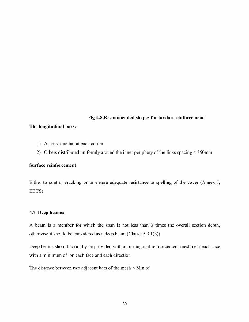
89
Fig-4.8.Recommended shapes for torsion reinforcement
The longitudinal bars:-
1) At least one bar at each corner
2) Others distributed uniformly around the inner periphery of the links spacing < 350mm
Surface reinforcement:
Either to control cracking or to ensure adequate resistance to spelling of the cover (Annex J,
EBCS)
4.7. Deep beams:
A beam is a member for which the span is not less than 3 times the overall section depth,
otherwise it should be considered as a deep beam (Clause 5.3.1(3))
Deep beams should normally be provided with an orthogonal reinforcement mesh near each face
with a minimum of on each face and each direction
The distance between two adjacent bars of the mesh < Min of
90
Chapter-5
Slabs:
5.1. IntroductionDefinition: A slab is a member for which the minimum panel dimension is not less than 5
times the overall slab thickness(Clause 5.3.1(4))
Slab may be supported on two sides and having the bending predominantly in one direction only
called one way slab and the slab supported on four sides and having the bending in both sides
called two slabs. And there is a difference in steel provision in the one way and two way. In both
slabs steel is provided in both X and Y directions but in one way the steel parallel to short
direction provided is main reinforcement and in the other direction providing steel is called
secondary or distribution steel. But in two slabs the steel provided in the both directions is main
reinforcement.
Slabs:
Criteria EBCS-2 EC-2 BS-8110 IS 456-2000
Main bars in Tension:
Clause 9.3.1.1(1) 0.26 0.26 0.0013 bh Slab is usually
designed as beam of
one meter width to
carry moment over a
strip of “1” meter
Clause 9.3.1.1(1)
0.04
0.04bd 0.04bh Slab is usually
designed as beam of
one meter width to
carry moment over a

91
strip of “1” meter
Secondary transverse bars
Clause 9.3.1.1(2)
0.2 for one way slabs
0.2for single way
slabs
0.002bh 0.15% of total cross
section if mild steel is
used. And 0.12% of
total cross section if is
used.
----------------- 0.04bd 0.04bh ----------
Spacing of bars:
------------------
--------
Clause 9.3.1.1(3)
Principle reinforcement
3h400mm
S e c o n d a r y
reinforcement
3.5h,
Areas of maximum
moment or areas of
concentrated loads
Main
3h400mm
S e c o n d a r y
reinforcement
3.5h
Places of
m a x i m u m
moment
Main
3d or
750mm
3D or 300 mm (
whichever is smaller)

92
Principal
2h
Secondary
2h
Secondary
Punching shear:
Links Clause 9.4.3(2) Link leg = 0.053 T o t a l =
0.4ud/0.87
For slabs nominal
shear stress shall not
exceed. Shear
reinforcements in slabs
should be avoided
since they workout
c u m b e r s o m e
andexpensive. Hence,
if increase the
thickness of slab and
redesign.
Spacing of links:
Clause 9.4.3(1)
0.75d
0.75d 0.75d
-------
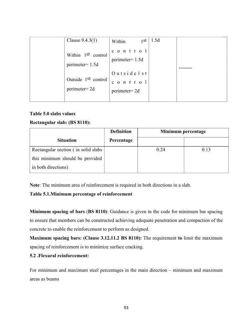
93
Clause 9.4.3(1)
Within 1st control
perimeter= 1.5d
Outside 1st control
perimeter= 2d
Within 1st
c o n t r o l
perimeter= 1.5d
O u t s i d e 1 s t
c o n t r o l
perimeter= 2d
1.5d
--------
Table 5.0 slabs values
Rectangular slab: (BS 8110):
Situation
Definition
Percentage
Minimum percentage
Rectangular section ( in solid slabs
this minimum should be provided
in both directions)
0.24 0.13
Note: The minimum area of reinforcement is required in both directions in a slab.
Table 5.1.Minimum percentage of reinforcement
Minimum spacing of bars (BS 8110): Guidance is given in the code for minimum bar spacing
to ensure that members can be constructed achieving adequate penetration and compaction of the
concrete to enable the reinforcement to perform as designed.
Maximum spacing bars: (Clause 3.12.11.2 BS 8110): The requirement to limit the maximum
spacing of reinforcement is to minimize surface cracking.
5.2 .Flexural reinforcement:
For minimum and maximum steel percentages in the main direction – minimum and maximum
areas as beams

94
i.e.
Secondary transverse reinforcement > 20% of the principal reinforcement (main reinforcement)
in one way slabs.
Areas near supports transverse reinforcement to principal top bars is not necessary where there is
no transverse bending moment.
Minimum reinforcement (IS-456-2000):
The mild steel reinforcement in either direction in slabs shall not be less than 0.15% of the cross
sectional area and in case of high deformed bars or welded wire fabric are used is 0.12%.
Maximum diameter bar in the slab: (IS-456-2000):
The diameter of reinforcing bars shall not exceed one eight of the total thickness of the slab.
5.2.1. Spacing of bars:
<, slabs.
For the principle reinforcement 3h400mm
For secondary reinforcement 3.5h 450mm
h-is the total depth of the slab.
In areas with concentrated loads or areas of maximum moment those provisions become
respectively
The principle reinforcement 2h
For secondary reinforcement 3h400mm
Curtailment: As beams except for the “shift” rule may be used.
Where partial fixity exists, not taken into design:
Internal supports:of in adjacent span.
End supports:of in adjacent span
This top reinforcement should extend0.2 adjacent spans.
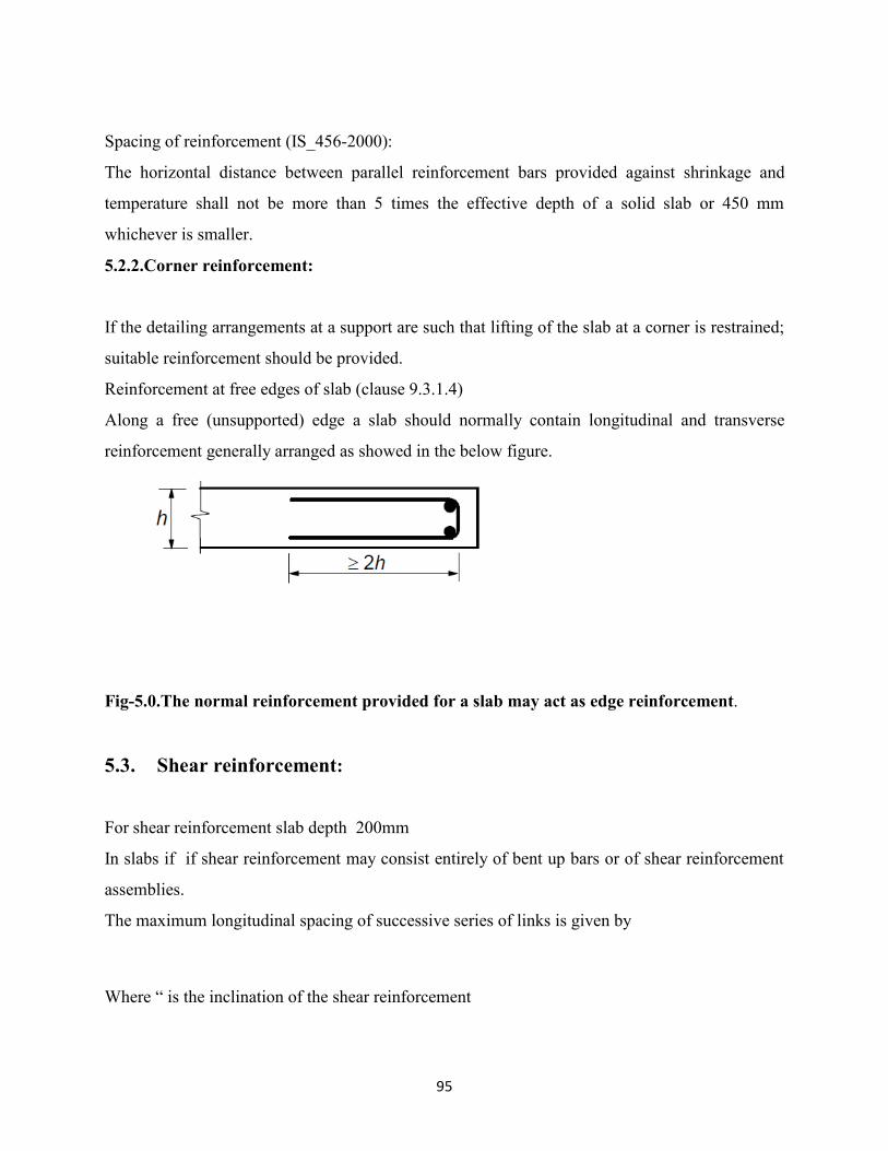
95
Spacing of reinforcement (IS_456-2000):
The horizontal distance between parallel reinforcement bars provided against shrinkage and
temperature shall not be more than 5 times the effective depth of a solid slab or 450 mm
whichever is smaller.
5.2.2.Corner reinforcement:
If the detailing arrangements at a support are such that lifting of the slab at a corner is restrained;
suitable reinforcement should be provided.
Reinforcement at free edges of slab (clause 9.3.1.4)
Along a free (unsupported) edge a slab should normally contain longitudinal and transverse
reinforcement generally arranged as showed in the below figure.
Fig-5.0.The normal reinforcement provided for a slab may act as edge reinforcement.
5.3. Shear reinforcement:
For shear reinforcement slab depth 200mm
In slabs if if shear reinforcement may consist entirely of bent up bars or of shear reinforcement
assemblies.
The maximum longitudinal spacing of successive series of links is given by
Where “ is the inclination of the shear reinforcement

96
The maximum longitudinal spacing of bent up bars is given by
The maximum transverse spacing of shear reinforcement should not exceed 1.5d
5.4. Flat slabs:
Support conditions of the slab determine the detailing of slab. The slab may be supported on
columns or walls or beams. Therefore slab supported directly by columns are called flat slabs
Arrangement of top reinforcement should reflect behavior under working conditions.
At internal columns for reinforcement of area 0.5 should be placed in a width =0.25 panel width.
At least two bottom bars should pass through internal columns in each orthogonal direction.
Design reinforcement at edge and corner reinforcement should be placed within the “be”
Note: y can be >cy Note: z can be >cz and y can be > cy
a) Edge column b) Corner column
Note: y is the distance from the edge of the slab to the innermost face of the column.Effective
width “be” of flat slab

97
Fig-5.1.Edge and corner column reinforcement
5.4.1. Punching shear reinforcement:
Punching shear does not use the variable strutinclinate method and is similar to BS 8110
methods.
Where punching shear reinforcement is required it should be placed between the loaded
area/column and kd inside the control perimeter at which shear reinforcement is no longer
required. It should be provided in at least two perimeters of link legs. The spacing of the link leg
perimeters should not exceed 0.75d.
The spacing of link legs around a perimeter should not exceed 1.5d within the first control
perimeter (2d from loaded area), and should not exceed 2d for perimeters outside the first control
perimeter where that part of the perimeter is assumed to contribute to the shear capacity.
For bent down bars as arranged in Figure one perimeter of link legs may be considered sufficient
Bent up bars passing through the loaded area or at a distance not exceeding 0.25d from this areamay be used as punching shear reinforcement.
Where shear reinforcement is required the area of link leg (or equivalent) is given by
(1.5 sin
Where” = is the angle between the shear reinforcement and the main steel (i.e the vertical links)=1
is the spacing of shear links in the radial direction
Spacing of the shear links in the tangential direction

98
a) Spacing of links b) Spacing of bent-up bars
Fig-5.2.Punching shear reinforcement
Note: See 6.4.5 (4) for the value of k.
5.4.1.1.Load distribution and basic control perimeter:
(1) The basic control perimeter u1 may normally be taken to be at a distance 2.0d from the
loaded area and should be constructed so as to minimize its length
The effective depth of the slab is assumed constant and may normally be taken as:

99
Wheredy and dz are the effective depths of the reinforcement in two orthogonal directions.
Fig-5.3: Control perimeter near an opening
The basic control perimeter is set at 2d from the loaded area. The shape of control perimeter has
rounded corners.
The control perimeter at which shear reinforcement is not required should be calculated from
The outermost perimeter of shear reinforcement should be placed at a distance not greater than
“kd” (k=1.5) within the outer control perimeter.
EC-2 Table 1.1
Location Negative moments Positive moments
Column strip 60-80% 50-70%

100
Middle strip 40-20% 50-30%
Table-5.2.Distribution of design moments:
Notes: The total negative and positive moments to be resisted by the column and middle strips
together should always add up to 100%
The distribution of design moments given in BS8110
Column strip: hogging 75%, sagging 55%
Middle strip: hogging 25%, sagging 45%
Chapter-6
Columns

101
6.1. Introduction
Definition: Column or strut is a vertical compression member the effective length of which
exceeds three times its least lateral dimension.
The following are applicable for h< 4b
h-larger dimension of column
b-smaller dimension of column
Columns:
Criteria EBCS -2 New draft EC-2 BS 8110
IS 456-2000
Main bars in compression
Clause 9.5.1(2)
0.10
0.10 0.004bh 0.8% of gross
cross sectional
area
Clause 9.5.1(3)
0.04 - outside lap
0.08 - at laps
0.04bh 0.06bh 6% gross cross
sectional area
Links:
Minimu
m size
Clause 9.5.3(1)
Max of(0.25 or 6mm)
0.25 or 6mm 0.25 or 6mm
Should not less
than of largest
diameter of
longitudinal bars
or 5 mm
C l a u s e 9 . 5 . 3 ( 4 )
particular special
sections
min( 12
150mm from
min( 12
150mm from
restrained main bar
12
150mm from
restrained main bar
Min ( Least
lateral dimension
of the column ,
16 timesthe
diameter of the

102
restrained main bar s m a l l e s t
longitudinal bar ,
300 mm)
Table 6.0 Column values
BS 8110:
Main reinforcement:
In columns in addition to minimum percentages of steel there is a requirement for a minimum
number and diameter of bars.
In rectangular columns number of bars diameter of bars
In circular columns number of bars and diameter of the bars
Links:
In case of columns that when part or all of the main reinforcement is required to resist
compression the links should satisfy the following clause 3.12.7.1
a) Link diameter or
b) Link spacing 12 * diameter of the smallest compression bar.
These restrictions limit the buckling length of the main compression bars and also prevent the
steel from bursting out of the concrete.
Slenderness limits for columns: Clause 25.3 IS 456- 2000):
a) The unsupported length shall not exceed 60 times the least lateral dimension of the
column, (.
b) If in any given plane, one end of the column is unrestrained , b- width at that section,
and D- depth at that section.
Maximum areas of steel (Clause 3.12.6.2 BS 8110):
a) In vertically cast columns
b) In horizontally cast columns

103
c) Laps in vertically – horizontally cast columns
Note: The higher value in “b” reflects the better access for the placing and vibrations of concrete
in horizontally cast columns.
Fire resistance requirements for columns (Clause 4.3.1, part-2, BS 8110):
The fire resistance of a column depends on its minimum dimension and the concrete cover.
Fire
rating
(hours)
Minimum dimension Concrete
cover to
reinforcementFully Exposed 50% Exposed
1 200 160 25
2 300 200 35
3 400 300 35
4 450 350 35
Table 6.1 Fire resistance for columns
6.2. Column Reinforcement
6.2.1 Longitudinal reinforcement:
Longitudinal bar minimum dia=8mm
Total amount of longitudinal reinforcement >
Where- is the design yield strength of the reinforcement
Design axial compressive force.
Longitudinal reinforcement area <
Minimum number of bars in a circular column is “4”.And for columns having polygonal cross
section at least one bar should be placed at each corner.

104
Where direction of longitudinal bars changes (at changes in column sizes) more than 1:12 the
spacing of transverse reinforcement should be calculated.
Reinforcement in columns (IS-456-2000):
The cross section area of longitudinal reinforcement shall not be less than 0.8% nor more than
6% of the gross cross sectional area of the column.
The use of 6% reinforcement may involve practical difficulties in placing and compacting of
concrete hence lower percentage is recommended. Where bars from the columns below have to
be lapped with those in the column under consideration the percentage of steel shall usually not
exceed 4%.
In any column has larger cross sectional area than that required to support the load the minimum
percentage of steel shall be based upon the area of concrete required to resist the direct stress and
not upon the actual area.
Spacing of longitudinal reinforcement measured along the periphery of the column shall not
exceed 300 mm (Helically reinforced column)
The pitch of the helical reinforcement should satisfy the following requirement, it its strength is
enhanced by 1.05
a) not more than 75 mm
b) not more than core diameter of helix bars.
c) not less than 25 mm
d) not less than 3 times the diameter of helix bars
6.2.2. Transverse reinforcement:
It may be any of the forms like links, loops or helical spiral reinforcement.
The diameter of transverse reinforcement, greater of the following
a) > 6mm
b) f the maximum dia of longitudinal bar.
The diameter of the wires of welded mesh fabric for transverse reinforcement should not be less
than 5mm.
6.2.2.1. Spacing:

105
The spacing of transverse reinforcement along the column <
=min
b-least dimension of column
Should be reduced by a factor 0.6
a) In sections within “b” above or below a beam or slab
b) Near lapped joints where
A min of 3 bars is required in lap length.
Pitch
Fig-6.0.Column reinforcement restraining
No bar within a compression zone should be further than 150mm from a restrained bar.
Every longitudinal bar or bundle of bars in a corner should be held by transverse reinforcement.
AS3600-2009 Requirements for restraining single longitudinal bars in columns:
i) Every corner bar
ii) All bars where bars are spaced at centers > 150mm
iii) At least every alternative bar, where bar centers 150mm
For bundled bars, each bundle must be restrained.

106
Offset between column faces :( ACI 7.6.3.):
Where there is a change in size of a column. The slope of the inclined portion providing the
offset shall not exceed one in six (1 in 6). Where column verticals are offset bent, additional ties
are required and shall be placed not more than 6 in (150mm) from the point of the bend. For
practical purposes 3-closely spaced ties are usually used, one of which may be part of the
regularly spaced ties plus two extra ties.
Change bar arrangement between floors:-
When the bar arrangement is changed at a floor the bars may extend through terminate or require
separate dowels. Reinforcing steel at least equal in area to that in the column above must be
extended from the column below to lap bars above by the required lap length or butt splices must
be provided vertical bars from the column below, terminated for any reason are cutoff within 3in
(75mm) of the top of the finished floor.
6.3.Walls:
6.3.1. Introduction
This clause refers to reinforced concrete walls, length to thickness ratio
For walls subjected predominantly to out of plane bending the rules of slabs apply.
Clause 3.12.6.3 BS 8110:
Note: The subscript “sc” indicates the total area of main steel not necessarily steel in
compression
6.3.2. Reinforcement:

107
6.3.2.1. Vertical reinforcement:
The area of vertical reinforcement shall lie between
utside lap locations
at laps.
Where the minimum area of reinforcement controls in design half of this area should be located
at each face.
Spacing:
Distance between two adjacent vertical bars:
Minimum of the following
1) < 3 times wall thickness or
2) 400mm
6.3.2.2 Horizontal reinforcement:
It is running parallel to the faces of the wall (and to the free edges) should be provided at each
surface.
It should not be less than
Spacing:
Between two horizontal bars < 400mm
6.3.2.3. Transverse reinforcement:
Where total vertical reinforcement in the two faces exceeds links required as for columns.
The larger dimension shall < 4 times thickness of well.
Where the main reinforcement is placed nearest to the wall faces transverse reinforcement should
also be provided in the form of links with at least 4 per square meter of wall area.

108
Transverse reinforcement need not be provided where welded wire mesh and bars of diameter
are used with the concrete cover larger than 2.
6.3.3. Foundations of pile caps:
6.3.3.1.Reinforcement;
Reinforcement in a pile cap should be calculated either by using strut and tie or flexural methods
as appropriate.
Minimum bar diameter = should be provided = 8mm
The main tensile reinforcement to resist the action effects should be concentrated in the stress
zones between the tops of piles .If the area of this reinforcement is at least equal to the minimum
reinforcement evenly distributed bars along the bottom surface of the members may be omitted.
Also the sides and the top surface of the member may be unreinforced if there is no risk of
tension developing in these parts of the member.
The compression caused by the support reaction from the pile may be assumed to spread at 450
angles from the edge of the pile. This compression may be taken into account when calculating
the anchorage length.
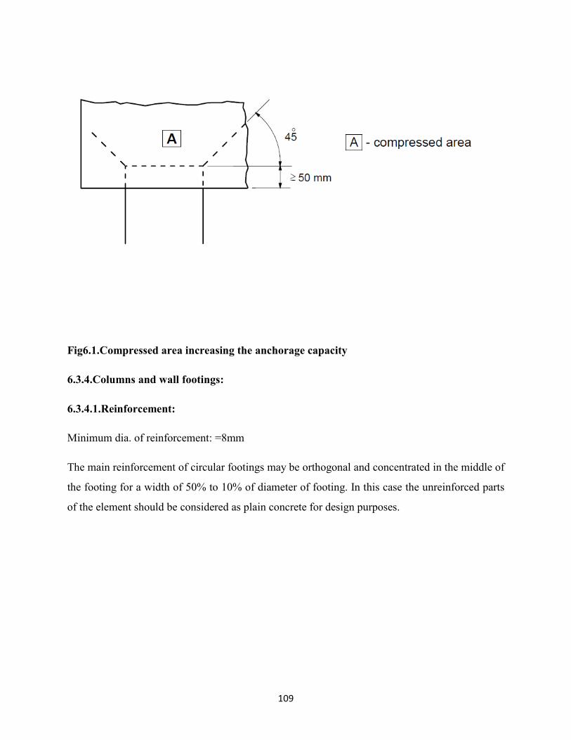
109
Fig6.1.Compressed area increasing the anchorage capacity
6.3.4.Columns and wall footings:
6.3.4.1.Reinforcement:
Minimum dia. of reinforcement: =8mm
The main reinforcement of circular footings may be orthogonal and concentrated in the middle of
the footing for a width of 50% to 10% of diameter of footing. In this case the unreinforced parts
of the element should be considered as plain concrete for design purposes.

110
Fig-6.2.Orthogonal reinforcement in circular spread footing on soil
If the action effects cause tension at the upper surface of the footing the resulting tensile stresses
should be checked and reinforced as necessary.
Tie beams may be used to eliminate the eccentricity of loading of the foundations. The beams
should be designed to resist the B.M’s and S.F’s.
A minimum bar diameter for the reinforcement resisting B.M’s should be provided.
The beams should also be designed for a minimum downward load of if the action of
compaction machinery can cause effects to the tie beams.
Column footing on rock:
Adequate transverse reinforcement should be provided to resist the splitting forces in the footing
when the ground pressure in the ultimate state exceeds ” This reinforcement may be distributed

111
uniformly in the direction of the splitting force over the height “h”. A minimum bar dia should
be provided. The splitting force may be calculated as follows.
Where “h” is lesser of “b” and “h”
a) Footing with h ≥ H b) section c) Footing with h < H
Fig 6.3: Splitting reinforcement in footing on rock
6.3.5. Bored piles:
For reinforced bored piles

112
Minimum longitudinal reinforcement related to piles cross section related to pile cross section
reinforcement should be distributed along the periphery of the section
Pile cross-section Ac
Minimum area of longitudinal
reinforcement: As,bpmin
Ac ≤ 0.5 m2 As ≥ 0.005 Ac
0.5 m2<Ac < 1.0 m2 As ≤ 25 cm2
Ac > 1.0 m2 As ≥ 0.0025Ac
Table6.2.Recommended minimum longitudinal reinforcement area in cast in place bored
Piles.
Longitudinal bar minimum dia16mm, piles should have at least 6-longitudinal bars.The clear
distance between bars < 200mm measured along the periphery of the pile.
6.3.6. Cast in place piles:
In the absence of other provisions the diameter used in the design calculations of cast in place
piles without permanent casing should be taken as (clause 2.3.4.2(1))
If dnom< 400 mm d=dnom-20mm
If 400mm ≤ dnom≤ 1000mm d=0.95 dnom
If dnom> 1000mm d= dnom-50mm
dnom- is the nominal diameter of the pile.
113
Chapter-7
Serviceability limit states7.1. IntroductionFrom the past century material strengths continued to increase. At the same time the overall
safety factor used in design has been reducing. Result of this development makes the ultimate
limit state is no longer critical. Design now often depends on serviceability limit states.
Common serviceability limit states are covered under this section: These are
1) Stress limitation
2) Crack control
3) Deflection control.
Limitation: Vibration control not covered in this standard.
Assumptions: In the calculation of stresses and deflections.
a) Cross section shall be assumed to be uncracked provided that the flexural tensile stress
does not exceed

114
b) The value of may be taken as or provided that the calculation for minimum tension
reinforcement is also based on same value.
c) For purposes of calculating crack widths and tension stiffening should be used.
7.2. Stresslimitation (Clause 7.2)
7.2.1. Concrete:
To avoid longitudinal cracks, micro cracks or high levels of creep, the compressive stress in
concrete shall be limited, where they could result in unacceptable effects on the function of the
structure.
Longitudinal cracks:
An area exposed to environments of exposure classes .Longitudinal cracks may lead to a
reduction of durability these occurs under the characteristic combination of loads exceeds a
critical value. If other measures are absented such as increase in the cover to reinforcement in the
compressive zone or confinement by transverse reinforcement, it may appropriate to limit the
compressive stress to a value in areas exposed to above said.
is given in national annex=0.6
Creep:
Liner creep and nonlinear creep.
If the stress in concrete under quasi permanent loads
- Linear creep may be assumed.
Nonlinear creep considered
National Annex=0.45
7.2.2. Steel:
Tensile stresses in reinforcement shall be limited
1. To avoid inelastic strain
2. Unacceptable cracking or deformation.

115
Unacceptable cracking or deformation:
For the appearance unacceptable cracking or deformation may be assumed to be avoided if
a) Under the characteristic combination of loads the tensile stress in reinforcement does not
exceed
b) Where the stress is caused by an imposed deformation the tensile stress should not exceed
- National Annex- 0.8 and 1.0 respectively.
7.3. Crack control (Clause 7.2):
7.3.1. General considerations (Clause 7.3.1)
Cracking is normal in reinforced concrete structures subject to bending, shear or torsion or
tension resulting from either direct loading or restraint or imposed deformations. Cracking shall
be limited to an extent that will not impair the proper functioning or durability of the structure or
cause its appearance to be unacceptable. Cracks may be permitted to form without any attempt to
control their width provided they do not impair the functioning of the structure.
7.3.2. Limitation:
Other cause for cracks such as plastic shrinkage or expansive chemical reactions within the
hardened concrete –Their avoidance and control lie outside the scope of this section.
A limiting value for the calculated crack width “ taking into account the proposed function and
nature of the structure and the costs of limiting cracking should be established.
given in national annex.
EBCS-2, 2013(Draft)-Table 7.1N. Recommended values of (mm)
Exposure Class
Reinforced members and prestressed
members with unbounded tendons
Prestressed members with
bonded tendons
Quasi-permanent load combination Frequent load combination

116
X0,XC1 0.41 0.2
XC2,XC3,XC4
0.30.22
XD1,XD2,XD3,
XS1,XS2,XS3Decompression
Note 1: For X0, XC1 exposure classes, crack width has no influence on durability and this
limit is set to give generally acceptable appearance. In the absence of appearance conditions
this limit may be relaxed.
Note 2: For these exposure classes, in addition, decompression should be checked under the
quasi-permanent combination of loads.
Table-7.0. Recommended values of (mm)
Verification in SLS (Service limit state) may also be carried out using strut and tie models ‘e.g’
verification of steel stresses and crack width control, if approximate compatibility for strut and
tie models is ensured (In particular the position and direction of important struts should be
oriented according to linear elastic theory).When using strut and tie models with the struts
oriented according to the compressive stress trajectories
7.3.3. Flexural cracking: AS3600-2009
Crack spacing “s” varies between 0.5d and 1.5d and depends on
i) Steel area and distribution
ii) Cover
The average crack spacing decreases with time due to shrinkage.
Crack width “w” depends on
i) Steel stress
ii) Bar diameter and bar spacing
iii) Cover
iv) Adjacent crack spacing’s
It increases with time due to shrinkage. Maximum crack widths increase with time by a factor of
between 2 and 4.

117
Simplified approach for flexural crack control in As3600-2009(Clause 8.6.1 and 9.4.1):
For reinforced concrete beams and slabs cracking is deemed to be controlled ( Crack widths will
be less than 0.3 mm) if each of the following is satisfied.
i) The distance from the side or soffit of the member to the Centre of the nearest
longitudinal bar shall not exceed 100mm.
ii) The Centre to Centre spacing of bars near a tension face of beam or slab shall not
exceed 300mm. for a beam and the lesser of the two times the slab thickness and
300mm for slab.
iii) The Quantity of tensile reinforcement in abeam or slab provides an ultimate tensile
strength at least 20% higher than the cracking moment.
iv) The stress in the tensile steel is less than a limiting value.
7.4. Deflection control (Clause 7.4):-
The deformation of a member or structure shall not be such that it adversely affects it’s proper
functioning or appearance .Appropriate limiting values of deflection taking into account the
nature of the structure of the finishes, partitions and fixings and upon the function of the structure
should be established.
Derived from ES ISO 4356:-
1) From appearance and general utility:-
The calculated sag of a beam slab or cantilever subjected to quasi permanent loads
deflection, otherwise appearance and general utility of the structure is impaired. Pre
camber may be used to compensate for some or all of the deflection but any upward
deflection incorporated in the formwork should not generally exceed, The sag is assessed
relative to the supports.
2) From deflection that damage adjacent parts:

118
For the deflection after construction is normally an appropriate limit for quasi permanent
loads.
The limiting Span/depth ratio may be estimated using following expressions and multiplying this
by correction factors to allow for the type of reinforcement used and other variables. No
allowance has been made for any pre camber in the derivation of these expressions.
-----(a)
--------(b)
Where:
l/d is the limit span/depth
K is the factor to take into account the different structural systems
o is the reference reinforcement ratio =
is the required tension reinforcement ratio at mid-span to resist the moment due to the
design loads (at support for cantilevers)
’ is the required compression reinforcement ratio at mid-span to resist the moment due to
design loads (at support for cantilevers)
fck is in MPa units
Expressions (a) and (b) have been derived on the assumption that the steel stress under the
appropriate design load at SLS(Service limit state) at a cracked section at the mid span of a beam
or slab or at the support of a cantilever is 310 Mpa (corresponding roughly to )
Where other stress levels are used the values obtained using expressions (a) and (b)should be
multiplied by
Where is the tensile steel stress at mid span (at support for cantilevers) under design load at SLS.
is the area of steel provided at this section.
is the area of steel required this section for for ultimate limit state.

119
For flanged sections where the ratio of the flange breadth to rib breadth exceeds “3” the values
of given by expression (a) and (b) should be multiplied by 0.8
For beams and slabs other than flat slabs with spans exceeding 7m which support partitions liable
to be damaged by excessive deflections the values of given by expression (a) and (b) should be
multiplied by ( where is in meters.)
For flat slabs span greater than 8.5m supports partitions liable to be damaged by excessive
deflections the values of given by expression (a) and (b) should be multiplied by (where in
meters)
For the values of “k” – national Annex.
Basic ratios of span/ effective depth for reinforced concrete members without axial compression.
Structural System K
Concrete highly
stressed
= 1.5%
Concrete lightly
stressed
= 0.5%
Simply supported beam, one – or
two-way spanning simply supported
slab
11.0 14 20
End span of continuous beam or
one-way continuous slab or two-way
spanning slab continuous over one
long side
11.3 18 26

120
Interior span of beam or one-way or
two-way spanning slab
11.5 20 30
Slab supported on columns without
beams (flat slab) (based on longer
span)
11.2 17 24
Cantilever 0.4 6 8
Note 1: The values given have been chosen to be generally conservative and calculation may
frequently show that thinner members are possible.
Note 2: For 2-way spanning slabs, the check should be carried out on the basis of the shorter
span. For flat slabs the longer span should be taken.
Note 3: The limits given for flat slabs correspond to a less severe limitation than a mid-span
deflection of span/250 relative to the columns. Experience has shown this to be satisfactory
Table-7.1.Values for “K” and “”
Members which are not expected to be loaded above the level which would cause the tensile
strength of the concrete to be exceeded anywhere within the member should be considered to be
uncracked. Members which are expected to crack, but may not be fully cracked, will behave in a
manner intermediate between the uncracked and fully cracked conditions and, for members
subjected mainly to flexure, an adequate prediction of behavior is given by Expression below:
= ll + (1 - )l
Where
is the deformation parameter considered which may be, for example, a strain, a curvature,
or a rotation. (As a simplification, α may also be taken as a deflection -
l, ll are the values of the parameter calculated for the uncracked and fully cracked conditions,

121
respectively
is a distribution coefficient (allowing for tensioning stiffening at a section) given by Expression
= 0, for uncracked sections
- is a coefficient taking account of the influence of the duration of the loading or of repeated
loading on the average strain
= 1.0 for a single short-term loading
= 0.5 for sustained loads or many cycles of repeated loading
σsis the stress in the tension reinforcement calculated on the basis of a cracked section
σsris the stress in the tension reinforcement calculated on the basis of a cracked section under the
loading conditions causing first cracking
Note: σsr/σs may be replaced by Mcr/M for flexure or Ncr/N for pure tension, where Mcr is the
cracking moment and Ncr is the cracking force.
For loads with a duration causing creep, the total deformation including creep may be calculated
by using an effective modulus of elasticity for concrete according to Expression:
Where:
(,t0) is the creep coefficient relevant for the load and time interval (see 3.1.4)
Shrinkage curvatures may be assessed using Expression below
Where:
1/rcs is the curvature due to shrinkage

122
cs is the free shrinkage strain (see 3.1.4)
S is the first moment of area of the reinforcement about the centroid of the section
I is the second moment of area of the section
e is the effective modular ratio
e = Es/Ec,eff
S and I should be calculated for the uncracked condition and the fully cracked condition, the final
curvature being assessed by use of Expression
7.5. Environmental conditions (Given in Annex-A)
(1) P Exposure conditions are chemical and physical conditions to which the structure is
exposed in addition to the mechanical actions.
(2) Environmental conditions are classified according to Table 4.1, based on ES-EN 206-1.
(3) In addition to the conditions in Particular forms of aggressive or indirect action should be
considered including: Chemical attack, arising from e.g.
i) the use of the building or the structure (storage of liquids, etc)
ii) solutions of acids or sulfate salts (ES-206-1, ISO 9690)
iii) chlorides contained in the concrete (ES-EN206-1)
iv) alkali-aggregate reactions (ES-EN 206-1, National Standards)
Physical attack, arising from e.g.
i) temperature change
ii) abrasion
iii) Water penetration (ES-EN206-1).
Discussion

123
i) Regarding development length:: The EBCS code book s silent on the development
length of the bars in contact(i.e bundled). Therefore in the bundled bars the
development length of each bar shall be that for the individual bar , increased by 10%
fro two barsin contact, 20% for three bars in contact and 33% for four bars in contact.
The anchorages of the bars of a bundle can only be straight anchorages.
ii) Splicing in case of bundled bars, lapped splices of bundled bars shall be made by
splicing one bar at a time, such individual splices within a bundle shall be staggered
.For bundles of 2, 3, or 4 bar the staggering distance should be 1.2, 1.3 and 1.4 times
the anchorage length of the individual bars respectively.
iii) Where more than half of the bars are spliced at section or where splices are made at
points of maximum stress, special precautions shall be taken such as increasing the
length of the lap and or using spirals or closely spaced stirrups around the length of
the splice.
iv) Regarding the side face reinforcement: Where the depth of the beam exceeds 750mm
in case of beams without torsion and 450mm with torsion side face reinforcement
shall be provided. Side face reinforcement shall be provided along the two faces.
Total area of such reinforcement shall not be less than 0.1% of web area distributed
equally on two faces spacing not exceeding 300mm or b.
v) About reinforcement provision in two way slabs i.e., main and distribution. In two
way slabs reinforcement parallel to the short span of the slab shall be placed in the
bottom layer at mid span and in the top layer at support.
vi) EBCS has provided how to provide the reinforcement in beam column connection at
the end support but it was not provided about the beam column at intermediate and
beam-beam intersection for the provision of main reinforcement. Therefore at beam
column intersections ensure that the main beam bars avoid the main column bars.
And at beam-beam intersections main reinforcement may be so arranged that layers in
mutually perpendicular beams are at different levels. Thus to accommodate bottom
bars it is good practice to make secondary beams shallower than main beams at least
by 50mm.

124
vii) In columns for using helical reinforcement a reinforced column shall have at least six
bars of longitudinal reinforcement.
viii) Column connection with the footing: Column bars of diameter larger than 36mm in
compression can be spliced with dowels at the footing with bars of smaller sizes and
of necessary area. A dowel shall extend into a column a distance equal to the
development length of the column bar and into footing distance equal to development
length of the dowel. Where dowels are provided their dia. shall not exceed the
diameter of the column bars by more than 3mm.
ix) Flexural reinforcement preferably shall not be terminated in tension zone. If such bars
larger than 36mm lap splices shall not be used and also shall not be bundled.
x) Curtailment: Bars in bundle shall terminate at different points spaced apart by not less
than 40 times the bar diameter except for bundles stopping at a support.
xi) Force not applied to top of beam: Where a load transfer is through the bottom or side
of beam (for example where one beam frames into another) ensure that there is
sufficient suspension or hang up reinforcement at the unction in the main beam in the
form of stirrups to transfer the force to the top of the beam. If the load is large bent up
bars may also be used in addition to stirrups.
xii) Development length of the bars in tension or compression: The calculated tension or
compression at any bar at any section shall be developed on each side of the section
by an appropriate development length or end anchorage or by a combination thereof.
xiii) Fritz Leonhardt (1974)(Famous Professor) presents the following suggestions of
appropriate and inappropriate solutions for lap splices in order to avoid high
concentration of tensile stresses in the concrete around the bar that might cause
splitting cracks in concrete.

125
Inappropriate Lap Splice
The stress - here corresponds to the transversal component related to the bond stress.
Appropriate Lap Splice

126
Conclusion:
Though the EBCS also includes certain guidelines for the Detailing, the code majorly deals with
the design principles of the various members. The scope of this these is so wide , even then I
tried to incorporate which are very much required for detailing from EBCS new draft along with
the developed countries and developing countries.
Future work:
For future scope of the study
i) Can be further elaborated with the other detailing regarding stair cases , beam column
and beam-beam joints
ii) Can be applied for pre stress concrete
iii) Similarly for the earthquake code of EBCS-8 also can be formulated as detailing code.

127
Annex-A
Exposure classes related to environmental conditions in accordance with ES-EN 206-1
C l a s s
Designation
Description of the Environment Informative examples where exposure
classes may occur
1. No risk of corrosion or attack
X0
For concrete without reinforcement
or embedded metal: all exposures
except where there is freeze/thaw,
abrasion or chemical attack
For concrete with reinforcement or
embedded metal: very dry
Concrete inside buildings with very low air
humidity
2. Corrosion induced by carbonation
XC1Dry or permanently wet
Concrete inside buildings with low air
humidity Concrete permanently submerged
in water
XC2 Wet, rarely dry
Concrete surfaces subject to long-term
water contact
Many foundations
XC3 Moderate humidity
Concrete inside buildings with moderate or
high air humidity
External concrete sheltered from rain
XC4Cyclic wet and dry Concrete surfaces subject to water contact,
not within exposure class XC2
3. Corrosion induced by chlorides

128
XD1Moderate humidity Concrete surfaces exposed to airborne
chlorides
XD2 Wet, rarely dry
Swimming pools
Concrete components exposed to industrial
waters containing chlorides
XD3Cyclic wet and dry
Parts of bridges exposed to spray
containing chlorides ,pavements car park
slabs
4. Corrosion induced by chlorides from sea water
XS1Exposed to airborne salt but not in
direct contact with sea water
Structures near to or on the coast
XS2 Permanently submerged Parts of marine structures
XS3 Tidal, splash and spray zones Parts of marine structures
5. Freeze/Thaw Attack
XF1Moderate water saturation, without
de-icing agent
Vertical concrete surface exposed to rain
and freezing
XF2 Moderate water saturation, with
de-icing agent
Vertical concrete surfaces of road
structures exposed to freezing and airborne
de-icing agents
XF3High water saturation, without
de-icing agents
Horizontal concrete surfaces exposed to
rain and freezing
XF4 Road and bridge decks exposed to de-icing

129
High water saturation with de-icing
agents or sea water
agents Concrete surfaces exposed to direct
spray containing de-icing agents and freezing
Splash zone of marine structures exposed to
freezing
6. Chemical attack
XA1
Slightly aggressive chemical
environment according to ES-EN
206-1,Table 2
Natural soils and ground water
XA2
Moderately aggressive chemical
environment according to ES-EN 206-1,
Table 2
Natural soils and ground water
XA3High aggressive chemical environment
according to ES-EN 206-1, Table 2
Natural soils and ground water
References:1) ACI 318M-2005, Building code requirements for structural concrete (Metric)
2) Australian code AS3600-2009 of.
3) Bureau of Indian Standard, Hand book on concrete reinforcement and detailing,
SP-34-1987
4) Concrete society, Standard method of Detailing structural concrete, 3rd edition.
5) Department of Transport and main roads drafting and Design Presentation standards manual,
State of Queens land(Department of Transport and main roads) 2011
6) Ethiopian Building Code Standard Draft code-2013.
7) EURO CODE-2 But it is supplemented by number of other standards the following in
Particular but they are not referred, but quoted for educate the reader (A. EN10080-
steel for the reinforcement of concrete (1). B. EN ISO 17760 – Permitted welding

130
process for reinforcement (2), C.EN ISO 3766:2003- construction drawings simplified
representation of concrete reinforcement (3), D.EUROCODE-8- Design of structures
for EQ resistance (4)
8) J.E.Breen, J.O.Jirsa,R.Bergmeiter, andM.E.KergerDetailing for structural concrete
(Study conducted in cooperation with the U.S Department of Transportation, Federal
Highway Administration)
9) Jose Calavera, Manual for detailing Reinforced concrete structures to EC-2, Spon Press.
10) J.P.Jain and V.K.Ghanekar, Handbook for Limit state design of reinforced concrete
member, Structural engineering research center,Roorke.
11) Mark Fintel,CBS Publishersand distributorsHand book of concrete engineering,
2nd edition.
12) Robin Whittle failures in concrete structures(Case studies in reinforced and pre
stressed concrete) CRC Press.