thermometer cs - micro-epsilon€¦ · thermometer cs contents 1. safety ... - use the system in...
TRANSCRIPT
Instruction Manual
thermoMETER CS

MICRO-EPSILONMESSTECHNIKGmbH & Co. KGKönigbacher Strasse 15
94496 Ortenburg / Germany
Tel. +49 (0) 8542 / 168-0 Fax +49 (0) 8542 / 168-90e-mail [email protected]
Certified acc. to DIN EN ISO 9001: 2008
Infrared sensor

thermoMETER CS
Contents
1. Safety .......................................................................................................................................... 51.1 Symbols Used .................................................................................................................................................... 51.2 Warnings ............................................................................................................................................................ 51.3 Notes on CE Identification ................................................................................................................................. 61.4 Proper Use ......................................................................................................................................................... 71.5 Proper Environment ........................................................................................................................................... 7
2. Technical Data ............................................................................................................................ 82.1 Functional Principle............................................................................................................................................ 82.2 General Specifications ....................................................................................................................................... 82.3 Electrical Specifications ..................................................................................................................................... 92.4 Measurement Specifications ........................................................................................................................... 11
3. Delivery ..................................................................................................................................... 123.1 Unpacking ........................................................................................................................................................ 123.2 Storage ............................................................................................................................................................. 12
4. Optical Charts ........................................................................................................................... 13
5. LED Functions .......................................................................................................................... 145.1 Automatic Aiming Support ............................................................................................................................... 145.2 Self Diagnostic ................................................................................................................................................. 155.3 Temperature Code Indication .......................................................................................................................... 16
6. Installation ................................................................................................................................ 176.1 Mechanical Installation .................................................................................................................................... 176.2 Electrical Installation ........................................................................................................................................ 186.2.1 Analog Device (mV Output on OUT Pin) ......................................................................................................... 186.2.2 Analog Device (Thermocouple Type K Output on OUT t/c K Pins / only at Model CSTK-SF15) .................... 186.2.3 Digital Communication..................................................................................................................................... 196.2.4 Open Collector Output ..................................................................................................................................... 206.2.5 Direct Connection to an RS232 Interface on the Computer ........................................................................... 20
7. Maintenance ............................................................................................................................. 20
8. Schematic Circuit Diagrams for Maintenance Applications .................................................. 21
thermoMETER CS
9. Software .................................................................................................................................... 239.1 Installation ........................................................................................................................................................ 239.2 Minimum System Requirements ...................................................................................................................... 239.3 Main Features ................................................................................................................................................... 249.4 Communication Settings ................................................................................................................................. 24
10. Digital Command Set ............................................................................................................... 25
11. Basics of Infrared Thermometry .............................................................................................. 27
12. Emissivity .................................................................................................................................. 2812.1 Definition .......................................................................................................................................................... 2812.2 Determination of Unknown Emissivities .......................................................................................................... 2812.3 Characteristic Emissivities ............................................................................................................................... 29
13. Warranty .................................................................................................................................... 29
14. Service, Repair ......................................................................................................................... 30
15. Decommissioning, Disposal .................................................................................................... 30
Appendix
A 1 Accessories .............................................................................................................................. 31A 1.1 Mounting Accessories ..................................................................................................................................... 31A 1.2 Close Focus Optics .......................................................................................................................................... 32A 1.3 Air Purge Collars .............................................................................................................................................. 33A 1.4 Further Accessories ......................................................................................................................................... 34
A 2 Factory Default Settings ........................................................................................................... 35
A 3 Appendix A - Emissivity Table Metals .................................................................................... 38
A 4 Appendix B Emissivity Table Non Metals ............................................................................... 39
A 5 Appendix C - Smart Averaging ................................................................................................ 40
Page 5
Safety
thermoMETER CS
1. Safety
The handling of the system assumes knowledge of the instruction manual.
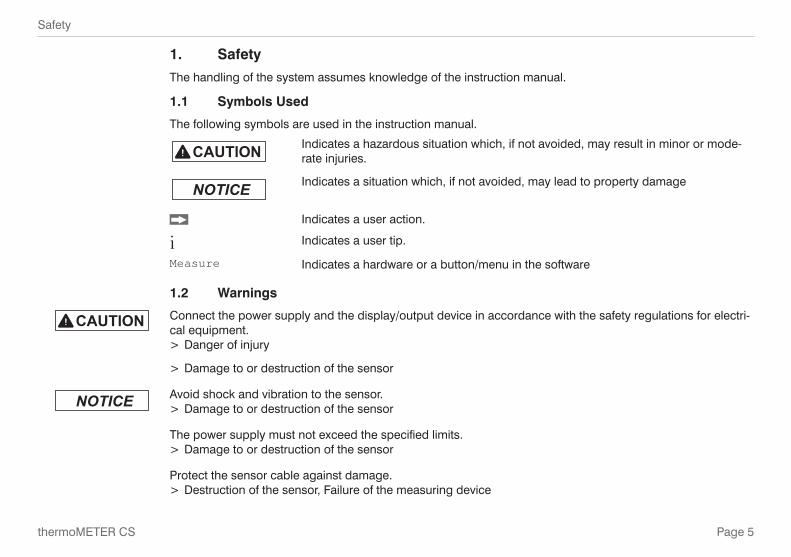
1.1 Symbols Used
The following symbols are used in the instruction manual.
Indicates a hazardous situation which, if not avoided, may result in minor or mode-rate injuries.
Indicates a situation which, if not avoided, may lead to property damage
Indicates a user action.
i Indicates a user tip.
Measure Indicates a hardware or a button/menu in the software
1.2 Warnings
Connect the power supply and the display/output device in accordance with the safety regulations for electri-cal equipment.
> Danger of injury
> Damage to or destruction of the sensor
Avoid shock and vibration to the sensor. > Damage to or destruction of the sensor
The power supply must not exceed the specified limits. > Damage to or destruction of the sensor
Protect the sensor cable against damage. > Destruction of the sensor, Failure of the measuring device
Page 6
Safety
thermoMETER CS
Do not kink the sensor cable and bend the sensor cable in tight radius. The minimum bending radius is 14 mm (static). A dynamic movement is not allowed.
> Damage to the sensor cable, failure of the measuring device
No solvent-based cleaning agents may have an effect on the sensor (neither for the optics nor the housing) > Damage to or destruction of the sensor
1.3 Notes on CE Identification
The following applies to the thermoMETER CS: - EU directive 2004/108/EC - EU directive 2011/65/EU, “RoHS“ category 9
Products which carry the CE mark satisfy the requirements of the quoted EU directives and the European standards (EN) listed therein. The EC declaration of conformity is kept available according to EC regulation, article 10 by the authorities responsible at
MICRO-EPSILON MESSTECHNIKGmbH & Co. KGKönigbacher Straße 15
94496 Ortenburg / Germany
The system is designed for use in industry and laboratory and satisfies the requirements.
Page 7
Safety
thermoMETER CS
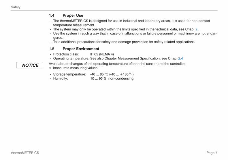
1.4 Proper Use - The thermoMETER CS is designed for use in industrial and laboratory areas. It is used for non-contact
temperature measurement. - The system may only be operated within the limits specified in the technical data, see Chap. 2.. - Use the system in such a way that in case of malfunctions or failure personnel or machinery are not endan-
gered. - Take additional precautions for safety and damage prevention for safety-related applications.
1.5 Proper Environment - Protection class: IP 65 (NEMA 4) - Operating temperature: See also Chapter Measurement Specification, see Chap. 2.4
Avoid abrupt changes of the operating temperature of both the sensor and the controller. > Inaccurate measuring values
- Storage temperature: -40 ... 85 °C (-40 ... +185 °F) - Humidity: 10 ... 95 %, non-condensing

Page 8
Technical Data
thermoMETER CS
2. Technical Data
2.1 Functional Principle
The sensors of the CS series are non-contact infrared temperature sensors. They calculate the surface tem-perature based on the emitted infrared energy of objects, see Chap. 11. The sensor housing of the CS is made of stainless steel (IP 63) and contains the complete sensor electronics. The CS has a fixed mounted connection cable.
i The sensors CS are sensitive optical systems. Please use only the thread for mechanical installation.
Avoid mechanical violence on the sensor > Destruction of the sensor.
2.2 General Specifications
Environmental rating IP 63Ambient temperature -20 ... 80 °CStorage temperature -40 ... 85°CRelative humidity 10 ... 95 °C, non condensingMaterial Stainless steel
Dimensions M12x1, 85 mm longWeight 58 gCable length 1 m (standard), 3 m, 8 m, 15 mKabeldurchmesser 4,3 mmVibration IEC 68-2-6: 3 G, 11 - 200 Hz, any axisShock IEC 68-2-27: 50 G, 11 ms, any axis

Page 9
Technical Data
thermoMETER CS
2.3 Electrical Specifications
Used pin Function
OUT IN/OUT
x Analog 0 - 5 V 1) or 0 - 10 V 2)/ scalable
x Alarm output voltage adjustable; N/O or N/C
x Alarm 3-state alarm output (three voltage level for no alarm, pre-alarm, alarm)
x Alarm programmable open collector output
[0 - 30 V DC/ 50 mA] 4)
x Temp. Code Temp. Code Output
(open collector [0 - 30 V DC/ 50 mA] 4)
x Input programmable functions: - external emissivity adjustment - ambient temperature compensation - triggered signal output and peak hold function 5)
x x Serial digital 3) uni- (burst mode) or bidirectional
OUT t/c K Analog Thermocouple output type K (only at model CSTK-SF15); alterna-tively selectable to the mV output (software necessary)
Status LED green LED with programmable functions: - alarm indication (threshold independent from alarm outputs) - automatic aiming support - self diagnostics - temperature code indication
Page 10
Technical Data
thermoMETER CS
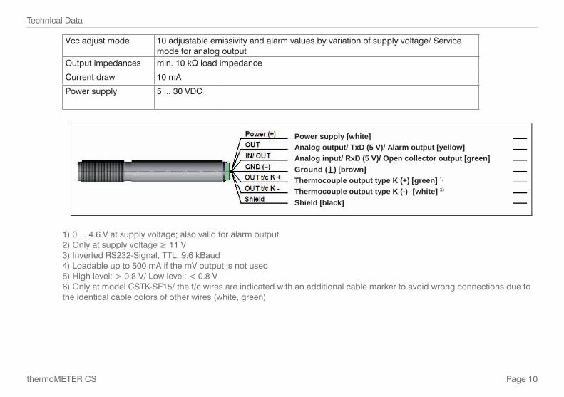
Vcc adjust mode 10 adjustable emissivity and alarm values by variation of supply voltage/ Service mode for analog output
Output impedances min. 10 kΩ load impedance
Current draw 10 mA
Power supply 5 ... 30 VDC
Power supply [white]
Analog output/ TxD (5 V)/ Alarm output [yellow]
Analog input/ RxD (5 V)/ Open collector output [green]
Ground ( ) [brown]
Thermocouple output type K (+) [green] 1)
Thermocouple output type K (-) [white] 1)
Shield [black]
1) 0 ... 4.6 V at supply voltage; also valid for alarm output2) Only at supply voltage ≥ 11 V3) Inverted RS232-Signal, TTL, 9.6 kBaud4) Loadable up to 500 mA if the mV output is not used5) High level: > 0.8 V/ Low level: < 0.8 V 6) Only at model CSTK-SF15/ the t/c wires are indicated with an additional cable marker to avoid wrong connections due to the identical cable colors of other wires (white, green)
Page 11
Technical Data
thermoMETER CS
2.4 Measurement Specifications
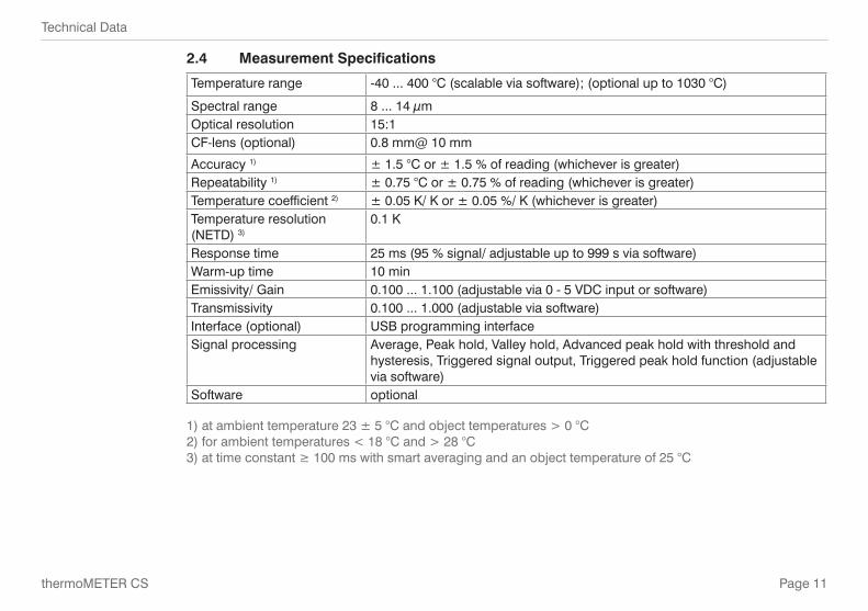
Temperature range -40 ... 400 °C (scalable via software); (optional up to 1030 °C)
Spectral range 8 ... 14 µmOptical resolution 15:1CF-lens (optional) 0.8 mm@ 10 mm
Accuracy 1) ± 1.5 °C or ± 1.5 % of reading (whichever is greater)Repeatability 1) ± 0.75 °C or ± 0.75 % of reading (whichever is greater)Temperature coefficient 2) ± 0.05 K/ K or ± 0.05 %/ K (whichever is greater)Temperature resolution (NETD) 3)
0.1 K
Response time 25 ms (95 % signal/ adjustable up to 999 s via software)Warm-up time 10 minEmissivity/ Gain 0.100 ... 1.100 (adjustable via 0 - 5 VDC input or software)Transmissivity 0.100 ... 1.000 (adjustable via software)Interface (optional) USB programming interfaceSignal processing Average, Peak hold, Valley hold, Advanced peak hold with threshold and
hysteresis, Triggered signal output, Triggered peak hold function (adjustable via software)
Software optional
1) at ambient temperature 23 ± 5 °C and object temperatures > 0 °C2) for ambient temperatures < 18 °C and > 28 °C3) at time constant ≥ 100 ms with smart averaging and an object temperature of 25 °C
Page 12
Delivery
thermoMETER CS
3. Delivery
3.1 Unpacking
1 thermoMETER CS sensor
1 Connection cable
2 Mounting nuts
1 Instruction manual
Check the delivery for completeness and shipping damage immediately after unpacking. In case of damage or missing parts, please contact the manufacturer or supplier.
Optional accessories you will find in the Chapters - Mounting Accessories, see Chap. A 1.1 - CF Lens, see Chap. A 1.2 - Air Purge Collars, see Chap. A 1.3 - Further Accessories, see Chap. A 1.4
3.2 Storage - Storage temperature: -40 ... 85 °C (-40 ... +185 °F) - Humidity: 10 ... 95 %, non-condensing

Page 13
Optical Charts
thermoMETER CS
4. Optical Charts
The following optical charts show the diameter of the measuring spot in dependence on the distance between measuring object and sensor. The spot size refers to 90 % of the radiation energy. The distance is always measured from the front edge of the sensor housing/ CF-lens holder/ air purge.
Fig. 1 Optical chart (15:1)
i The size of the measuring object and the optical resolution of the infrared thermometer determine the maximum distance between sensor and measuring object. In order to prevent measuring errors the object should fill out the field of view of the optics completely. Consequently, the spot should at all times have at least the same size like the object or should be smaller than that.
Fig. 2 Optical chart (15:1) with CF-lens (0.8 mm@ 10 mm)
Page 14
LED Functions
thermoMETER CS
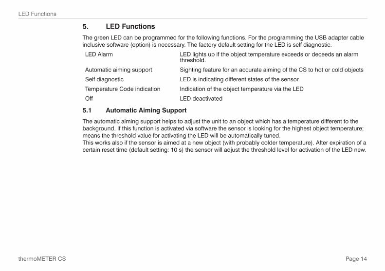
5. LED Functions
The green LED can be programmed for the following functions. For the programming the USB adapter cable inclusive software (option) is necessary. The factory default setting for the LED is self diagnostic.
LED Alarm LED lights up if the object temperature exceeds or deceeds an alarm threshold.
Automatic aiming support Sighting feature for an accurate aiming of the CS to hot or cold objects
Self diagnostic LED is indicating different states of the sensor.
Temperature Code indication Indication of the object temperature via the LED
Off LED deactivated
5.1 Automatic Aiming Support
The automatic aiming support helps to adjust the unit to an object which has a temperature different to the background. If this function is activated via software the sensor is looking for the highest object temperature; means the threshold value for activating the LED will be automatically tuned. This works also if the sensor is aimed at a new object (with probably colder temperature). After expiration of a certain reset time (default setting: 10 s) the sensor will adjust the threshold level for activation of the LED new.

Page 15
LED Functions
thermoMETER CS
5.2 Self Diagnostic
With this function the current status of the sensor will be indicated by different flash modes of the LED.
If activated, the LED will show one of five possible states of the sensor:
Status LED mode
Normal intermittent off - - - - -
Sensor overheated fast flash - - - - - - - - - -
Out of measuring range double flash -- -- -- -- -- --
Not stable intermittent on
Alarm fault always on
i At a supply voltage (Vcc) ≥ 12 V it takes about 5 minutes until the sensor works in a stable mode. Therefore, after switching on the unit, the LED will show a not stable state for up to 5 minutes.
Sensor overheated: The internal temperature probes have detected an invalid high internal temperature of the CS.
Out of meas. range: The object temperature is out of measuring range.
Not stable: The internal temperature probes have detected an unequally internal temperature of the CS.
Alarm fault: Current through the switching transistor of the open-collector output is too high.
Page 16
LED Functions
thermoMETER CS
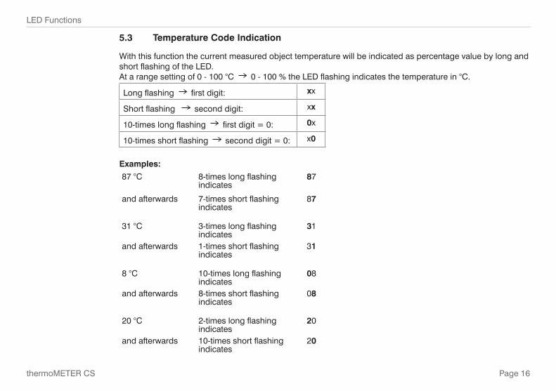
5.3 Temperature Code Indication
With this function the current measured object temperature will be indicated as percentage value by long and short flashing of the LED. At a range setting of 0 - 100 °C 0 - 100 % the LED flashing indicates the temperature in °C.
Long flashing first digit: xx
Short flashing second digit: xx
10-times long flashing first digit = 0: 0x
10-times short flashing second digit = 0: x0
Examples:
87 °C 8-times long flashing indicates
87
and afterwards 7-times short flashing indicates
87
31 °C 3-times long flashing indicates
31
and afterwards 1-times short flashing indicates
31
8 °C 10-times long flashing indicates
08
and afterwards 8-times short flashing indicates
08
20 °C 2-times long flashing indicates
20
and afterwards 10-times short flashing indicates
20
Page 17
Installation
thermoMETER CS
6. Installation
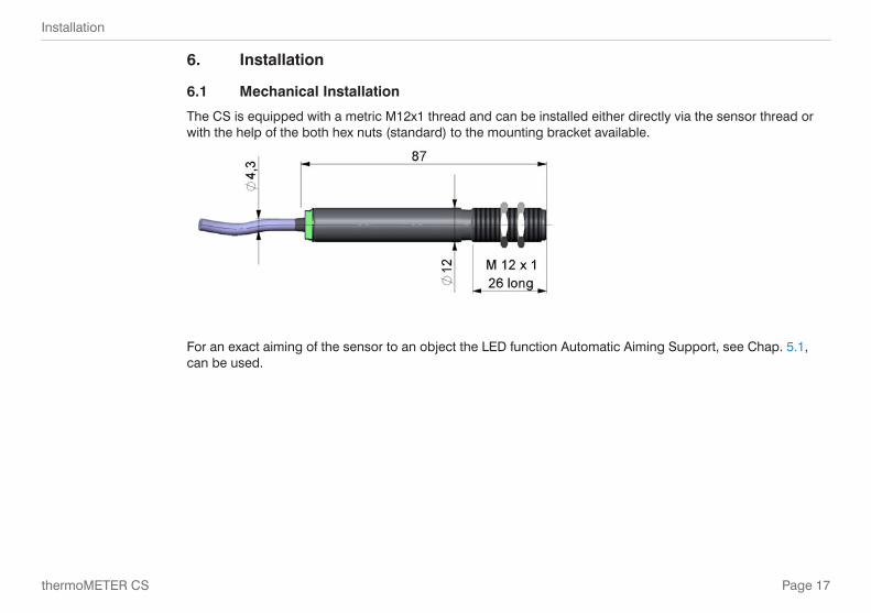
6.1 Mechanical Installation
The CS is equipped with a metric M12x1 thread and can be installed either directly via the sensor thread or with the help of the both hex nuts (standard) to the mounting bracket available.
For an exact aiming of the sensor to an object the LED function Automatic Aiming Support, see Chap. 5.1, can be used.

Page 18
Installation
thermoMETER CS
6.2 Electrical Installation
6.2.1 Analog Device (mV Output on OUT Pin)
The output impedance must be ≥ 10 kΩ.
6.2.2 Analog Device (Thermocouple Type K Output on OUT t/c K Pins / only at Model CSTK-SF15)
The output impedance must be ≥ 20 kΩ.
On the model CSTK-SF15 you can choose between a mV output (0 - 5 or 0 - 10 V; scalable via software) and a thermocouple output type K. The factory default setting is 0 - 3.5 V (according to 0 - 350 °C); the thermocouple output is inactive, see Chap. A 2.
Page 19
Installation
thermoMETER CS
To activate the thermocouple output the USB adapter cable and the software is needed. This output supplies a voltage according to the characteristic curve type K. If you want to extend this output you have to use a suitable thermocouple extension cable (NiCr-Ni).
i The shield [black] on the CS is not connected to GND [brown]. In any case it is necessary to connect the shield to ground or GND (whichever works best)!
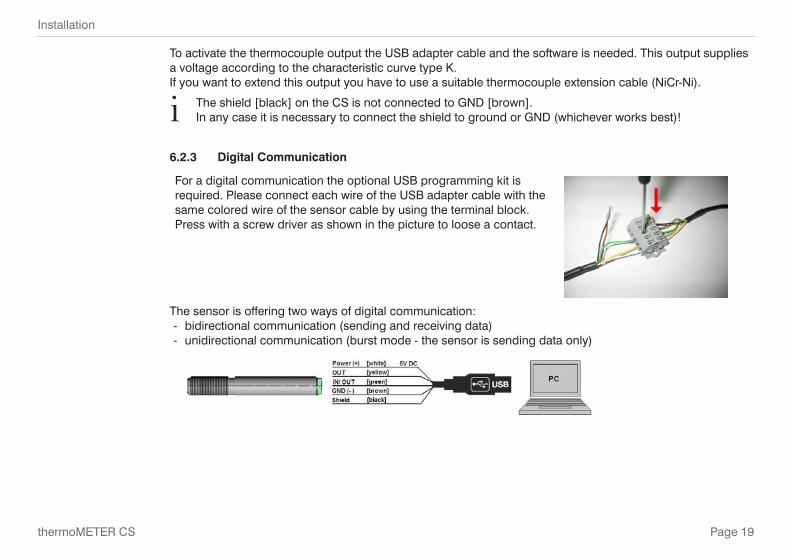
6.2.3 Digital Communication
For a digital communication the optional USB programming kit is required. Please connect each wire of the USB adapter cable with the same colored wire of the sensor cable by using the terminal block. Press with a screw driver as shown in the picture to loose a contact.
The sensor is offering two ways of digital communication: - bidirectional communication (sending and receiving data) - unidirectional communication (burst mode - the sensor is sending data only)

Page 20
Maintenance
thermoMETER CS
6.2.4 Open Collector Output
The open collector output is an additional alarm output on the CS and can control an external relay e.g. In addition the analog output can be used simultaneously.
6.2.5 Direct Connection to an RS232 Interface on the Computer
The CS works with a UART voltage of 3.3 V. For a bidirectional RS232 connection of the sensor the following interface circuits can be used: MAX3380 or MAX3321 (manufacturer: Maxim).
7. Maintenance
Lens cleaning: Blow off loose particles using clean compressed air. The lens surface can be cleaned with a soft, humid tissue moistened with water or a water based glass cleaner.
i Never use cleaning compounds which contain solvents (neither for the lens nor for the housing).
Page 21
Schematic Circuit Diagrams for Maintenance Applications
thermoMETER CS
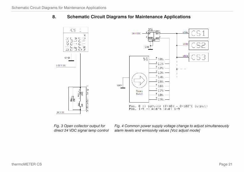
8. Schematic Circuit Diagrams for Maintenance Applications
Fig. 3 Open collector output for direct 24 VDC signal lamp control
Fig. 4 Common power supply voltage change to adjust simultaneously alarm levels and emissivity values [Vcc adjust mode]
Page 22
Schematic Circuit Diagrams for Maintenance Applications
thermoMETER CS
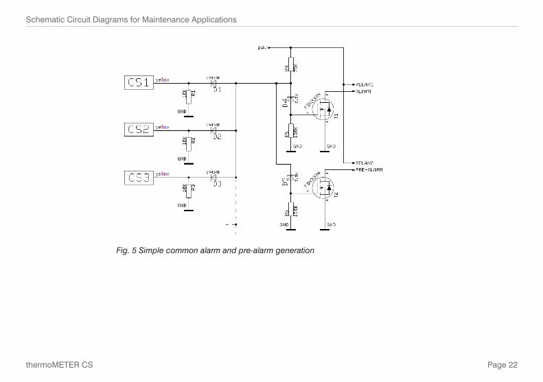
Fig. 5 Simple common alarm and pre-alarm generation
Page 23
Software
thermoMETER CS
9. Software
9.1 Installation
Insert the installation CD into the according drive on your computer. If the autorun option is activated the installation wizard will start automatically. Otherwise please start setup.exe from the CR-ROM. Follow the instructions of the wizard until the installation is finished. The installation wizard will place a launch icon on the desktop and in the start menu. If you want to uninstall the software from your system please use the uninstall icon in the start menu.
i You will find a detailed software manual on the CD.
9.2 Minimum System Requirements - Windows XP, Vista, 7 - USB interface - Hard disc with at least 30 MByte free space - At least 128 MByte RAM - CD-ROM drive

Page 24
Software
thermoMETER CS
9.3 Main Features
- Graphic display for temperature trends and automat-ic data logging for analysis and documentation
- Complete sensor setup and remote controlling - Adjustment of signal processing functions - Programming of outputs and functional inputs
9.4 Communication Settings
Serial Interface
Baud rate: 9600 baud
Data bits: 8
Parity: none
Stop bits: 1
Flow control: off
Protocol
All sensors of the CS series are using a binary protocol. To get a fast communication the protocol has no ad-ditional overhead with CR, LR or ACK bytes. To power the sensor the control signal „DTR“ has to be set.
Page 25
Digital Command Set
thermoMETER CS
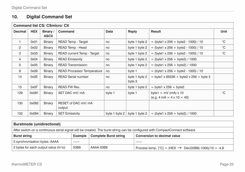
10. Digital Command Set
Command list CS/ CSmicro/ CX
Decimal HEX Binary / ASCII
Command Data Reply Result Unit
1 0x01 Binary READ Temp - Target no byte 1 byte 2 = (byte1 x 256 + byte2 - 1000) / 10 °C
2 0x02 Binary READ Temp - Head no byte 1 byte 2 = (byte1 x 256 + byte2 - 1000) / 10 °C
3 0x03 Binary READ current Temp - Target no byte 1 byte 2 = (byte1 x 256 + byte2 - 1000) / 10 °C
4 0x04 Binary READ Emissivity no byte 1 byte 2 = (byte1 x 256 + byte2) / 1000
5 0x05 Binary READ Transmission no byte 1 byte 2 = (byte1 x 256 + byte2) / 1000
9 0x09 Binary READ Processor Temperature no byte 1 = (byte1 x 256 + byte2 - 1000) / 10
14 0x0E Binary READ Serial number no byte 1 byte 2 byte 3
= byte1 x 65536 + byte2 x 256 + byte 3
15 0x0F Binary READ FW Rev. no byte 1 byte 2 = byte1 x 256 + byte2
129 0x081 Binary SET DAC mV/ mA byte 1 byte 1 byte1 = mV (mA) x 10 (e.g. 4 mA = 4 x 10 = 40)
°C
130 0x082 Binary RESET of DAC mV/ mA output
132 0x084 Binary SET Emissivity byte 1 byte 2 byte 1 byte 2 = (byte1 x 256 + byte2) / 1000
Burstmode (unidirectional)
After switch on a continuous serial signal will be created. The burst string can be configured with CompactConnect software.
Burst string Example Complete Burst string Conversion to decimal value
2 synchronisation bytes: AAAA ------ ------
2 bytes for each output value (hi lo) 03B8 AAAA 03B8 Process temp. [°C] = (HEX Dec(03B8)-1000)/10 = -4.8
Page 26
Digital Command Set
thermoMETER CS
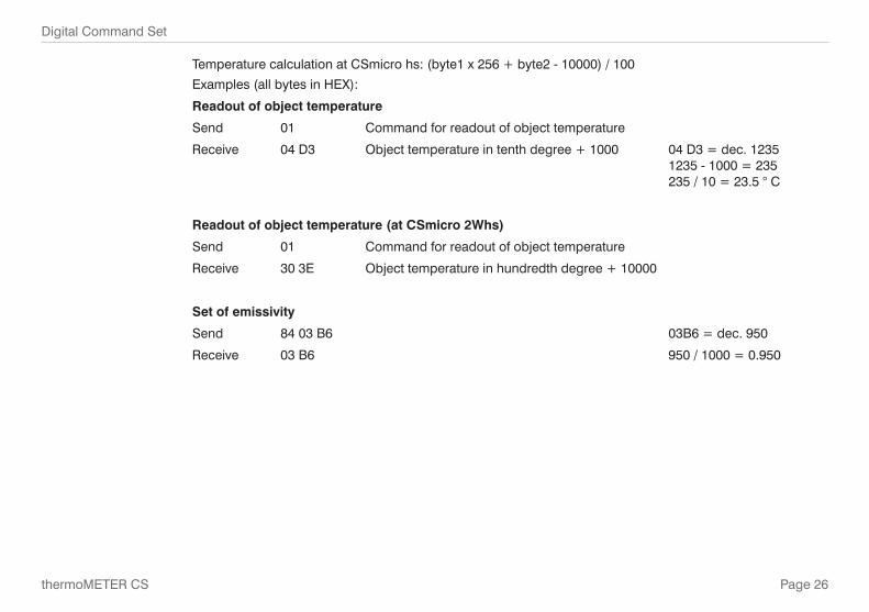
Temperature calculation at CSmicro hs: (byte1 x 256 + byte2 - 10000) / 100
Examples (all bytes in HEX):
Readout of object temperature
Send 01 Command for readout of object temperature
Receive 04 D3 Object temperature in tenth degree + 1000 04 D3 = dec. 1235 1235 - 1000 = 235 235 / 10 = 23.5 ° C
Readout of object temperature (at CSmicro 2Whs)
Send 01 Command for readout of object temperature
Receive 30 3E Object temperature in hundredth degree + 10000
Set of emissivity
Send 84 03 B6 03B6 = dec. 950
Receive 03 B6 950 / 1000 = 0.950
Page 27
Basics of Infrared Thermometry
thermoMETER CS
11. Basics of Infrared Thermometry
Depending on the temperature each object emits a certain amount of infrared radiation. A change in the temperature of the object is accompanied by a change in the intensity of the radiation. For the measurement of „thermal radiation“ infrared thermometry uses a wave-length ranging between 1 µ and 20 µm. The intensity of the emitted radiation depends on the material. This material contingent constant is described with the help of the emissivity which is a known value for most materials (see enclosed table emissivity).
Infrared thermometers are optoelectronic sensors. They calculate the surface temperature on the basis of the emitted infrared radiation from an object. The most important feature of infrared thermometers is that they en-able the user to measure objects contactless. Consequently, these products help to measure the temperature of inaccessible or moving objects without difficulties. Infrared thermometers basically consist of the following components:
- Lens - Spectral filter - Detector - Electronics (amplifier/ linearization/ signal processing)
The specifications of the lens decisively determine the optical path of the infrared thermometer, which is char-acterized by the ratio Distance to Spot size. The spectral filter selects the wavelength range, which is relevant for the temperature measurement. The detector in cooperation with the processing electronics transforms the emitted infrared radiation into electrical signals.

Page 28
Emissivity
thermoMETER CS
12. Emissivity
12.1 Definition
The intensity of infrared radiation, which is emitted by each body, depends on the temperature as well as on the radiation features of the surface material of the measuring object. The emissivity (e - Epsilon) is used as a material constant factor to describe the ability of the body to emit infrared energy. It can range between 0 and 100 %. A “blackbody“ is the ideal radiation source with an emissivity of 1.0 whereas a mirror shows an emissivity of 0.1. If the emissivity chosen is too high, the infrared thermometer may display a temperature value which is much lower than the real temperature - assuming the measuring object is warmer than its surroundings. A low emissivity (reflective surfaces) carries the risk of inaccurate measuring results by interfering infrared radiation emitted by background objects (flames, heating systems, chamottes). To minimize measuring errors in such cases, the handling should be performed very carefully and the unit should be protected against reflecting radiation sources.
12.2 Determination of Unknown Emissivities - First, determine the actual temperature of the measuring object with a thermocouple or contact sensor.
Second, measure the temperature with the infrared thermometer and modify the emissivity until the dis-played result corresponds to the actual temperature.
- If you monitor temperatures of up to 380 °C you may place a special plastic sticker (emissivity dots - part number: TM-ED-LS) onto the measuring object, which covers it completely. Now set the emissivity to 0.95 and take the temperature of the sticker. Afterwards, determine the temperature of the adjacent area on the measuring object and adjust the emissivity according to the value of the temperature of the sticker.
- Cove a part of the surface of the measuring object with a black, flat paint with an emissivity of 0.98. Adjust the emissivity of your infrared thermometer to 0.98 and take the temperature of the colored surface. After-wards, determine the temperature of a directly adjacent area and modify the emissivity until the measured value corresponds to the temperature of the colored surface.

Page 29
Warranty
thermoMETER CS
12.3 Characteristic Emissivities
In case none of the methods mentioned above help to determine the emissivity you may use the emissivity tables, see Chap. A 3, see Chap. A 4. These are average values, only. The actual emissivity of material de-pends on the following factors:
- Temperature - Measuring angle - Geometry of the surface - Thickness of the material - Constitution of the surface (polished, oxidized, rough, sandblast) - Spectral range of the measurement - Transmissivity (e.g. with thin films)
13. Warranty
All components of the device have been checked and tested for perfect function in the factory. In the unlikely event that errors should occur despite our thorough quality control, this should be reported immediately to MICRO-EPSILON. The warranty period lasts 12 months following the day of shipment. Defective parts, except wear parts, will be repaired or replaced free of charge within this period if you return the device free of cost to MICRO-EPSILON. This warranty does not apply to damage resulting from abuse of the equipment and devices, from forceful handling or installation of the devices or from repair or modifications performed by third parties. No other claims, except as warranted, are accepted. The terms of the purchasing contract apply in full. MICRO-EPSILON will specifically not be responsible for eventual consequential damages. MICRO-EPSILON always strives to supply the customers with the finest and most advanced equipment. De-velopment and refinement is therefore performed continuously and the right to design changes without prior notice is accordingly reserved. For translations in other languages, the data and statements in the German language operation manual are to be taken as authoritative.

Page 30
Service, Repair
thermoMETER CS
14. Service, Repair
In the event of a defect on the sensor, controller or the sensor cable please send us the affected parts for repair or exchange.
In the case of faults the cause of which is not clearly identifiable, the entire measuring system must be sent back to:
MICRO-EPSILON MESSTECHNIK GmbH & Co. KG Königbacher Str. 15 94496 Ortenburg / Germany
Tel. +49 (0) 8542/ 168-0 Fax +49 (0) 8542 / 168-90 [email protected]
For customers in USA applies:
Send the affected parts or the entire measuring system back to:
MICRO-EPSILON USA 8120 Brownleigh Dr. Raleigh, NC 27617 /USA
Tel. +1 919 / 787-9707 Fax +1 919 / 787-9706 [email protected] www.micro-epsilon.com
For customers in Canada or South America applies:
Please contact your local distributor.
15. Decommissioning, Disposal Disconnect the sensor cables.
Incorrect disposal may cause harm to the environment. Dispose of the device, its components and accessories, as well as the packaging materials in compli-
ance with the applicable country-specific waste treatment and disposal regulations of the region of use.
Page 31
Service, Repair
thermoMETER CS
Appendix
A 1 Accessories
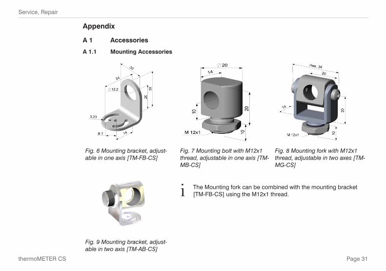
A 1.1 Mounting Accessories
Fig. 6 Mounting bracket, adjust-able in one axis [TM-FB-CS]
Fig. 7 Mounting bolt with M12x1 thread, adjustable in one axis [TM-MB-CS]
Fig. 8 Mounting fork with M12x1 thread, adjustable in two axes [TM-MG-CS]
i The Mounting fork can be combined with the mounting bracket [TM-FB-CS] using the M12x1 thread.
Fig. 9 Mounting bracket, adjust-able in two axis [TM-AB-CS]

Page 32
Service, Repair
thermoMETER CS
A 1.2 Close Focus Optics
The optional CF-lens allows the measurement of small objects. The CF optics can also be combined with a laminar air purge:
Fig. 10 CF-lens [TM-CF-CS] Fig. 11 Laminar air purge with integrated CF-lens [TM-APLCF-CS]
i If the CF-lens is used, the transmission has to be set to 0.78. To change this value the optional USB-Kit (including software) is necessary.

Page 33
Service, Repair
thermoMETER CS
A 1.3 Air Purge Collars
The lens must be kept clean at all times from dust, smoke, fumes and other contaminants in order to avoid reading errors. These effects can be reduced by using an air purge collar. Make sure to use oil-free, techni-cally clean air, only.
Fig. 12 Standard air purge collar; fits to the mounting bracket; hose connection: 3x5 mm [TM-AP-CS]
Fig. 13 Laminar air purge collar - the side air outlet prevents a cooling down of the object in short distances; hose connection: 3x5 mm [TM-APL-CS]
A combination of the Laminar air purge collar with the bottom sec-tion of the Mounting fork allows an adjustment in two axes. [TM-APL-CS + TM-MG-CS]
i The needed amount of air (ca. 2 ... 10 l/ min.) depends on the application and the installation conditions on-site.
Page 34
Service, Repair
thermoMETER CS
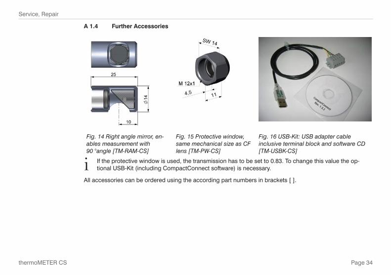
A 1.4 Further Accessories
Fig. 14 Right angle mirror, en-ables measurement with 90 °angle [TM-RAM-CS]
Fig. 15 Protective window, same mechanical size as CF lens [TM-PW-CS]
Fig. 16 USB-Kit: USB adapter cable inclusive terminal block and software CD [TM-USBK-CS]
i If the protective window is used, the transmission has to be set to 0.83. To change this value the op-tional USB-Kit (including CompactConnect software) is necessary.
All accessories can be ordered using the according part numbers in brackets [ ].
Page 35
Service, Repair
thermoMETER CS
A 2 Factory Default Settings
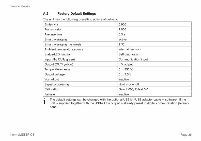
The unit has the following presetting at time of delivery:
Emissivity 0.950
Transmission 1.000
Average time 0.3 s
Smart averaging active
Smart averaging hysteresis 2 °C
Ambient temperature source internal (sensor)
Status-LED function Self diagnostic
Input (IN/ OUT/ green) Communication input
Output (OUT/ yellow) mV output
Temperature range 0 ... 350 °C
Output voltage 0 ... 3.5 V
Vcc adjust inactive
Signal processing Hold mode: off
Calibration Gain 1.000/ Offset 0.0
Failsafe inactive
i The default settings can be changed with the optional USB kit (USB adapter cable + software). If the unit is supplied together with the USB-kit the output is already preset to digital communication (bidirec-tional.
Page 36
Service, Repair
thermoMETER CS
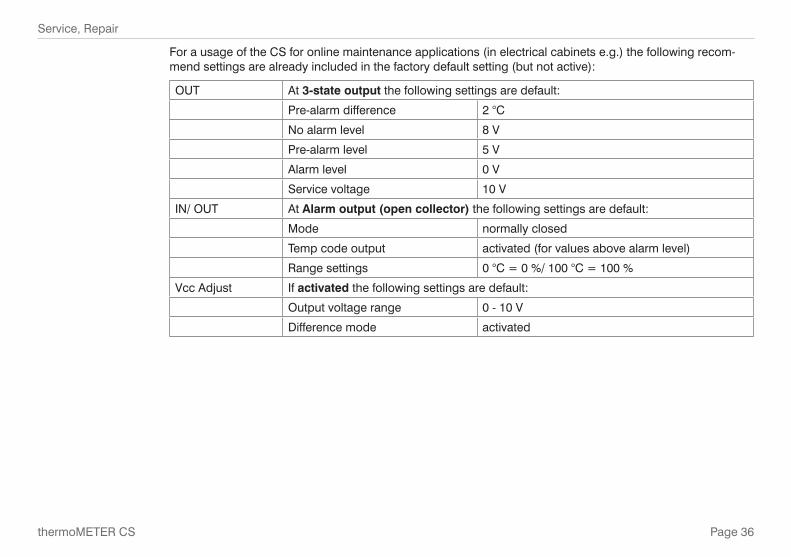
For a usage of the CS for online maintenance applications (in electrical cabinets e.g.) the following recom-mend settings are already included in the factory default setting (but not active):
OUT At 3-state output the following settings are default:
Pre-alarm difference 2 °C
No alarm level 8 V
Pre-alarm level 5 V
Alarm level 0 V
Service voltage 10 V
IN/ OUT At Alarm output (open collector) the following settings are default:
Mode normally closed
Temp code output activated (for values above alarm level)
Range settings 0 °C = 0 %/ 100 °C = 100 %
Vcc Adjust If activated the following settings are default:
Output voltage range 0 - 10 V
Difference mode activated

Page 37
Service, Repair
thermoMETER CS
Alarm level Alarm value (IN/ OUT pin) Vcc
1 40 °C 11 V
2 45 °C 12 V
3 50 °C 13 V
4 55 °C 14 V
5 60 °C 15 V
6 65 °C 16 V
7 70 °C 17 V
8 75 °C 18 V
9 80 °C 19 V
10 85 °C 20 V

Page 38
Service, Repair
thermoMETER CS
A 3 Appendix A - Emissivity Table Metals
Material Typical Emissivity
Aluminium non oxidized 0.02 - 0.1
polished 0.02 - 0.1
roughened 0.1 - 0.3oxidized 0.2 - 0.4
Brass polished 0.01 - 0.05
roughened 0.3oxidized 0.5
Copper polished 0.03roughened 0.05 - 0.1
oxidized 0.4 - 0.8Chrome 0.02 - 0.2Gold 0.01 - 0.1Haynes alloy 0.3 - 0.8Inconel electro polished 0.15
sandblast 0.3 - 0.6
oxidized 0.7 - 0.95
Iron non oxidized 0.05 - 0.2rusted 0.5 - 0.7
oxidized 0.5 - 0.9forged, blunt 0.9
Iron, casted non oxidized 0.2oxidized 0.6 - 0.95
Material Typical Emissivity
Lead polished 0.05 - 0.1
roughened 0.4oxidized 0.2 - 0.6
Magnesium 0.02 - 0.1Mercury 0.05 - 0.15Molybdenum non oxidized 0.1
oxidized 0.2 - 0.6Monel (Ni-Cu) 0.1 - 0.14Nickel electrolytic 0.05 - 0.15
oxidized 0.2 - 0.5Platinum black 0.9Silver 0.02Steel polished plate 0.1
rustless 0.1 - 0.8heavy plate 0.4 - 0.6cold-rolled 0.7 - 0.9oxidized 0.7 - 0.9
Tin non oxidized 0.05Titanium polished 0.05 - 0.2
oxidized 0.05 - 0.6Wolfram polished 0.03 - 0.1Zinc polished 0.02
oxidized 0.1

Page 39
Service, Repair
thermoMETER CS
A 4 Appendix B Emissivity Table Non Metals
Material Typical Emissivity
Asbestos 0.95
Asphalt 0.,95
Basalt 0.7
Carbonnon oxidized 0.8 - 0.9
graphite 0.7 - 0.8
Carborundum 0.9
Ceramic 0.95
Concrete 0.95
Glass 0.85
Grit 0.95
Gypsum 0.8 - 0.95
Ice 0.98
Limestone 0.98
Paint non alkaline 0.9 - 0.95
Paper any color 0.95
Plastic > 50 µm non transparent 0.95
Rubber 0.95
Sand 0.9
Snow 0.9
Soil 0.9 - 0.98
Textiles 0.95
Water 0.93
Wood natural 0.9 - 0.95
Page 40
Service, Repair
thermoMETER CS
A 5 Appendix C - Smart Averaging
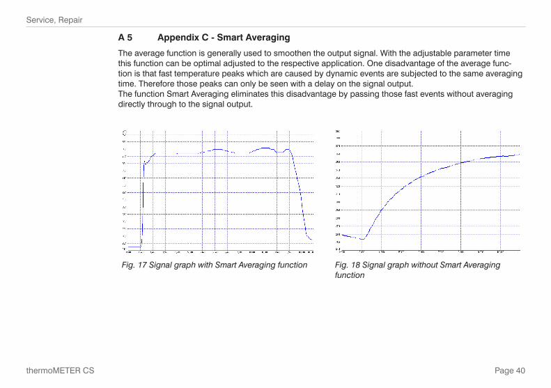
The average function is generally used to smoothen the output signal. With the adjustable parameter time this function can be optimal adjusted to the respective application. One disadvantage of the average func-tion is that fast temperature peaks which are caused by dynamic events are subjected to the same averaging time. Therefore those peaks can only be seen with a delay on the signal output. The function Smart Averaging eliminates this disadvantage by passing those fast events without averaging directly through to the signal output.
Fig. 17 Signal graph with Smart Averaging function Fig. 18 Signal graph without Smart Averaging function


MICRO-EPSILON MESSTECHNIK GmbH & Co. KG
Königbacher Str. 15 · 94496 Ortenburg / Germany
Tel. +49 (0) 8542 / 168-0 · Fax +49 (0) 8542 / 168-90
[email protected] · www.micro-epsilon.com
X9751203-B041026HDR
*X9751203-B04*
MICRO-EPSILON MESSTECHNIK