thermoelectric-based power generator … · microcontroller based security camera ... of a hot...
TRANSCRIPT

1 Copyright © 2012 by ASME
Proceedings of the ASME 2012 International Mechanical Engineering Congress & Exposition IMECE2012
November 9-15, 2012, Houston, Texas, USA
IMECE2012-89611
THERMOELECTRIC-BASED POWER GENERATOR FOR POWERING MICROCONTROLLER BASED SECURITY CAMERA
Robert Dell Center for Innovation and
Applied Technology Mechanical Engineering
The Cooper Union NY, USA
Runar Unnthorsson Dept. of Industrial Engineering, Mechanical
Engineering and Computer Science University of Iceland Reykjavik, Iceland
C.S. Wei Mechanical Engineering
The Cooper Union NY, USA
George W. Sidebotham Mechanical Engineering
The Cooper Union NY, USA
Magnus Thor Jonsson Dept. of Industrial Engineering, Mechanical
Engineering and Computer Science University of Iceland Reykjavik, Iceland
William Foley, Eric Ginzburg, Subashis Paul, Seyoon Kim,
Anthony Morris Mechanical Engineering
The Cooper Union NY, USA
ABSTRACT This paper presents the design, implementation and evaluation
of a thermoelectric-based point of use power generation system
with no moving parts. The power system was designed to be
robust and stable, capable of being clamped onto the outer wall
of a hot steam pipe with a temperature of over 160°C using
only heat pipes and natural convection of ambient air for
cooling.
Several systems were built and tested. One system was
built and tested at the Cooper Union in New York City. The
power generation was evaluated for different ambient and
steam pipe temperatures. The other systems were attached to an
85°C geothermal hot water pipe and a 100-120°C geothermal
steam pipe in Iceland. The Cooper Union system was used to
power two microcontroller based security cameras, one with
wireless LAN and another with cellular connectivity. Additional
testing of the PV voltage controller and the generator were
conducted in Iceland.
The results show that the system can be used to power
surveillance systems, even in remote locations without access to
the electrical grid. Because the system does not require grid
access, it will run constantly, and hence improve security.
Furthermore, the unit’s power generation is greater in colder
environments that substantially degrade battery performance.
Keywords: Thermoelectric generator, PV controller, heat pipe
ambient cooling, security camera
1. INTRODUCTION During the last decade we have witnessed many exciting and
innovative developments in mobile and handheld electronics
that have been made possible by incorporating Integrated
Circuits (ICs) and Microcontroller Units (MCUs). These
innovations have enabled low-power designs with new
connectivity and energy saving scenarios.
As the processing power of computers increased, the need
for transferring and sharing information became stronger.
Monitoring systems, which used to be run as standalone
systems, are now networked with other systems. In many cases
these systems are also control systems. Information sharing
provides a clearer overall picture of the process and allows for
more intelligent control.
The need for real time data or simplified data collection
from multiple sensors has driven the development of wired and
wireless sensor solutions. In the case of wired connections the
need for an external power supply is often eliminated by
enabling the sensors to function as parasites and draw their
power from the data line. Power for running wireless systems
is normally obtained from either batteries or internal power
supplies.
The advances in both low-power electronics and ambient
energy harvesting have led to significant industrial and
academic research of wire and battery free sensors and devices.

2 Copyright © 2012 by ASME
Wireless sensors powered by ambient energy can be found in
transportation, building automation, industry and more. This
technology eliminates the need to buy and replace batteries and
units can be left unattended in hazardous or hard to get to
places.
This paper presents the design and evaluation of a
thermoelectric-based energy harvesting system and its
implementation for powering cellular and wireless LAN
security cameras. The energy harvesting system is a highly
efficient thermoelectric-based point of use power generation
system which has no moving parts. This thermoelectric system
has many potential uses where uptime during blackout is
valuable. This includes condition monitoring applications in
many different settings involving a steady heat source, such as
steam sources in industrial and maritime settings, and waste hot
water sources.
The system’s basic design was presented at the GRC’s
annual meeting in 2011 [1]. In this paper the system’s
performance is evaluated at different pipe and ambient
temperatures. Furthermore, the paper demonstrates how the
system can be implemented for running a cellular security
camera.
The thermoelectric power system is protected by European
Patent Application No. 07862348.5, United States Patent
Application 20080142067 and Canadian application 2671995.
2. THE THERMOELECTRIC POWER GENERATOR The thermoelectric power generation system, shown in
Figure 1, consists of a pair of energy-transfer assemblies
mounted on opposite sides of a pipe. Each assembly consists of
a hot steel block, an array of three thermoelectric modules
wired in series and a cold block heat pipe system.
Figure 1: The Thermoelectric Power Generator
The hot and cold blocks respectively provide thermal channels
for heat transfer to and from the thermoelectric modules. In
order to increase the thermal conductivity of the thermal
interfaces, i.e. to make the thermal channels more effective, a
specially modified version of the Ambrosia HT high-
temperature thermal grease from Arctic Silver was used.
Thermoelectric Power
At the heart of a thermoelectric power generation system is one
or more thermoelectric modules (TEMs) which generate the
power. The power generation is based on the Peltier effect in
which an electromotive force (voltage and/or current) is
generated when two dissimilar metals are connected to form
two junctions maintained at different temperatures (ΔT). This
device is called a thermocouple. Individual thermocouples are
often used as temperature measurement devices, while
thermoelectric modules have multiple thermocouples in series
that use the temperature difference to generate more electricity.
The electrical output of a TEM is characterized by the
Seebeck Coefficient, , which relates the change in output
open circuit voltage, , to the temperature difference.
Equation 1 gives the differential form of the relation,
(1)
The output voltage is obtained by integrating between the high
and low plate temperatures, given by Equation 2:
(2)
where is the local coefficient and is the average Seebeck
coefficient between and . The modules used in this study
have approximately 0.055 - 0.07V/°C.
Figure 2 shows the schematic of a thermoelectric power
system. The system consists of a thermoelectric module, a
circuit load, , a high temperature heat transfer channel (hot
block) and a low temperature heat transfer channel (cold
block).
Figure 2: A schematic diagram of a thermoelectric power
system. The module is modeled electrically as a voltage
source, , with an internal resistance, .
3 Copyright © 2012 by ASME
The two heat transfer channels are required to maintain the
temperature difference between the two plates. The module is
modeled as a voltage source, , with an internal resistance, . If the module is short-circuited (closed, with zero load
resistance), the output voltage will be zero while an electrical
current, , is formed. The short circuit current is given by
Ohm’s Law;
(3)
When a circuit load, , is placed across the module, the
voltage across and current through it will be less than the
corresponding open and short circuit values. The voltage
across the load is
(4)
and the current is
(5)
The power generated is therefore
(6)
The power is maximized when the load resistance equals the
internal resistance, i.e. a classic case of impedance matching.
The maximum power achieved can be shown to be
(7)
The corresponding operating voltage and currents are half of
their open and short circuit counterparts.
The maximum possible thermal efficiency for a heat
engine operating between thermal reservoirs at temperatures TL
and TH (in absolute temperature units) is given by the Carnot
efficiency:
(8)
Quantitative determination of the thermal efficiency
(defined as output power to heat transfer rate to hot side, PL/QH)
requires detailed analysis of the heat transfer properties of hot
block, cold block and TEM. The manufacturer of the TEMs
used in this study applied proprietary software [9] given
measured plate temperatures and electrical output for one case.
For power production six thermoelectric modules (TEMs)
were wired in series. The ThermaTEC modules (Laird PB23
Series, HT8, 12) were designed to function in the temperature
ranges of typical steam systems.
These thermoelectric modules were originally designed for
thermoelectric cooling or heating. In this mode, the modules are
fed with electricity and heat is transferred (or pumped) from
one flat surface to the other. In this project the TEMs were
used in reverse i.e., a temperature difference was created
between the two flat surfaces to generate electricity.
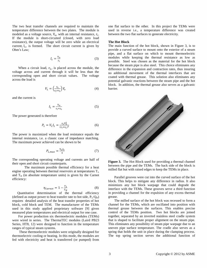
The Hot Block
The main function of the hot block, shown in Figure 3, is to
provide a curved surface to mount onto the exterior of a steam
pipe, and a flat surface on which to mount thermoelectric
modules while keeping the thermal resistance as low as
possible. Steel was chosen as the material for the hot block
because the steam pipe is also steel. This choice eliminates any
difference in the expansion and contraction rates, thus insuring
no additional movement of the thermal interfaces that are
coated with thermal grease. This solution also eliminates any
potential galvanic reactions between the steam pipe and the hot
block. In addition, the thermal grease also serves as a galvanic
barrier.
Figure 3. The Hot Block used for providing a thermal channel
between the pipe and the TEMs. The back side of the block is
milled flat but with raised edges to keep the TEMs in place.
Parallel grooves were cut into the curved surface of the hot
block. This helps to mitigate any difference in radius. It also
minimizes any hot block warpage that could degrade the
interface with the TEMs. These grooves serve a third function
in providing a channel for the expulsion of any excess thermal
grease.
The milled surface of the hot block was recessed to form a
channel for the TEMs, which are oscillated into position with
thermal grease between the surfaces. This enables precise
control of the TEMs position. Two hot blocks are joined
together, separated by an inverted stainless steel cradle system
that is shaped to facilitate proper alignment on the steam pipe.
This eliminates any possibility of steam pipe warpage due to an
uneven pipe surface temperature. The cradle also serves as a
spring that holds the unit in place during the clamping process.
The top spring section serves the additional function of

4 Copyright © 2012 by ASME
providing gripping points for the installation process, thus
minimizing any unnecessary contact with the hot steam pipe.
The Cold Block
The main function of the cold block system, shown in Figure 4,
is to provide a thermal channel between the cold plate of the
thermoelectric module array and the ambient environment.
Since the mode of heat transfer ultimately involves the
convective/radiative transfer of heat from a solid to ambient air,
the thermal goal is to provide a large exposed surface area of
material as close to the cold plate temperature as possible.
Figure 4: The cold block used for providing a thermal channel
between the TEMS and the ambient air.
The cold block system was fabricated by Noren Industries.
It consists of a copper mounting block which is mounted
directly on the TEMs, a 14 inch long heat pipe onto which 41
evenly spaced square aluminum fins are attached for efficient
ambient air cooling. In Figure 4, 4 inch square fins are used
except for the first 5, which are 3 inch to avoid the surface of
the steam pipe. Earlier less efficient prototypes used only 3 inch
fins. The heat pipe has an internal fluid transport mechanism
that, when properly designed, behaves thermally as a material
with a very high thermal conductivity (low thermal resistance).
There is a physical restriction in that the internal flow relies in
part on gravity, and its effectiveness is lower when placed
horizontally. A mild angle, i.e. 15 degrees from horizontal, is
sufficient for the heat pipe chosen.
The system is designed to rely primarily on natural
convection, and this imposes two important restrictions on the
fins. First, they must be close to vertical in order for the
ambient air to accelerate vertically between them. Second, the
spacing between the fins must be sufficiently large in order to
have minimal interference between the thermal boundary layers
of adjacent fins.
Heat pipes were chosen for this system for a variety of
reasons including lightness and low thermal resistance. Heat
pipes are lighter and transmit heat more efficiently than
standard solid metal heat sinks. A traditional heat fin would
create a substantial stress on the TEMs due to the cantilevered
weight.
Figure 5 shows a CAD rendering of a complete system
which consists of two mirrored assemblies mounted on
opposite sides of a pipe. The two heat pipes are splayed back
along the steam pipe which minimizes the space required for
the system. This geometry is important for safety concerns and
it enables installation in a one foot radius envelope around a
pipe. The natural convection around the hot pipe increases the
airflow and helps accelerating the cooling.
Figure 5: A CAD rendering of the complete thermoelectric
power system.
3. TEST SETUP The steam source used in the experiments at the Cooper Union
is shown in Figure 6. The source was an ESG Corporation 240
volt 3 phase SPEEDYELECTRIC 15A-2 electrode steam
generator with a BFCR-404 automatic water feed pump and
condensate return system. The 30 gallon condensate tank was
used as a water reservoir and the condensate was bled
manually.
The system operating pressure was set at maximum
pressure of 100 psig and an 80 psig minimum when the unit
automatically powered the electrodes until the maximum
pressure was again attained.
The steel piping used was 2 inch diameter with a 1 inch top
pipe in a closed loop configuration. The thermoelectric
generator was mounted on the exterior wall of the bottom
2 inch pipe, depicted in Figure 7.
5 Copyright © 2012 by ASME
Figure 6: The SPEEDYELECTRIC 15A-2 electrode steam
generator with a BFCR-404 automatic water feed pump.
Figure 7: Thermoelectric generator test bed at the Center for
Innovation and Applied Technology at the Cooper Union.
To determine additional generator performance in a variety
of ambient temperatures, a rectilinear insulated box was
fabricated to encase the thermoelectric generator. Figure 8
shows the box. This allowed the heat of the steam pipe and the
generator’s cold block to naturally heat the inside of the
enclosure, creating a confined space of air that served as the
ambient. Readings were taken every minute over the heat up
time frame of 40 minutes. Previous experiments established
system a voltage steady state response time to ambient
temperature changes of less than 1 minute. The enclosure
measured 1 meter long parallel to pipe and 0.75 meters in
width. It was 1 meter high and was attached to the back wall of
the test bed. The back wall consists of 3/4 inch painted
plywood and stud reinforced top layer over 2 inches of glass
insulation
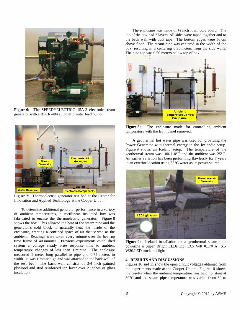
The enclosure was made of ½ inch foam core board. The
top of the box had 2 layers. All sides were taped together and to
the back wall with duct tape. The bottom edges were 50 cm
above floor. The steam pipe was centered in the width of the
box, resulting in a centering 0.35 meters from the side walls.
The pipe top was 0.50 meters below top of box.
Figure 8: The enclosure made for controlling ambient
temperature with the front panel removed.
A geothermal hot water pipe was used for providing the
Power Generator with thermal energy in the Icelandic setup.
Figure 9 shows an Iceland setup. The temperature of the
geothermal steam was 100-110°C and the ambient was 25°C.
An earlier variation has been performing flawlessly for 7 years
in an exterior location using 85°C water as its power source.
Figure 9: Iceland installation on a geothermal steam pipe
powering a Super Bright LEDs Inc. 13.5 Volt 0.170 A ST-
W30.LED truck tail light
4. RESULTS AND DISCUSSIONS
Figures 10 and 11 show the open circuit voltages obtained from
the experiments made at the Cooper Union. Figure 10 shows
the results when the ambient temperature was held constant at
30°C and the steam pipe temperature was varied from 30 to

6 Copyright © 2012 by ASME
160. Figure 11 shows the results when the steam temperature
was held constant at 160°C and the ambient was varied
between 28°C and 55°C. Both figures verify the linear
relationship between steam temperature and voltage, and
ambient air temperature and voltage.
When the TEMs are wired in series, the amperage is
constant and the voltage is additive. All of the thermoelectric
generators used 6 TEMs in series.
Figure 10: System open circuit voltage as a function of steam
temperature, ambient 30°C.
Figure 11: System open circuit voltage as a function of
ambient temperature. Steam temperature 160°C.
Figure 12 shows a multimeter reading from the
experiments when the steam pipe temperature was held
constant at 160°C. The reading was taken when the ambient
temperature was at 30°C. The maximum power that the
thermoelectric power generator can provide in this settings is
6.1 W – estimated using Equation 7.
Figure 12: Steady state open circuit voltage (left) and short
circuit amperage (right) with an ambient temperature of 30°C
and a steam temperature of 160°C.
The Carnot Efficiency in this temperature range is 30% as
calculated using Equation 8. Using the same temperature
configurations in Figure 12, the hot block temperature was
130.4°C and the cold block temperature was 80.6°C, when
measured using K-type thermocouples inserted into the center
of both blocks at a distance of 6mm from the thermoelectric
modules.
Figure 13: Thermocouple placement.
Using Laird Tech TEG Modeling Software [9] the
efficiency of the thermoelectric system was 2.6% using these
measurements. The second law efficiency (actual over Carnot)
is therefore 8.6%. Based on Equation 2, the average Seebeck
Coefficient was 0.42 V/°C.
Melcor HT-4-12-40 thermoelectric modules were used in
the earlier versions of the thermoelectric generator. The Melcor
TEMs provide lower amperage but higher voltage than the
Laird ThermaTEC modules. Earlier tests on the less efficient
generator designs using 3 inch fins demonstrated the linear
relationship between voltage and amperage. These designs
produced open circuit voltage of 17 Volts and short circuit
amperage of .600 A under the same test bed conditions as used
in this project. Figure 14 shows the I-V relationship of the
earlier design. The load was provided using a RS series
resistance substitution box from IET labs Inc. The point on the
voltage axis (zero current) is the open circuit voltage of 17.2 V,
and the point on the current axis (zero voltage) is the short
0 2 4 6 8
10 12 14 16 18 20 22
20 70 120 170
Steam Temperature [°C]
12 13 14 15 16 17 18 19 20 21 22
25 35 45 55 65
Vo
lta
ge
(V
)
Average Ambient Temperature [C]

7 Copyright © 2012 by ASME
circuit current (0.6 A). The plot is linear between these two
points, with a slope equal to 24.4 Ω.
Figure 14: System voltage as a function of current for various
electrical loads
The current design of the thermoelectric power generator
with the 4 inch fins was assembled and tested using the Melcor
TEMs. In identical steam and ambient temperatures, it
produced 31.2 V open circuit and 0.89 amps short circuit,
resulting in a maximum 6.9 steady state Watts.
Figure 15: Voltage controller, battery and security camera
A Manson Engineering Industrial Ltd SBC – 7112 Photo
Voltaic charge controller was used to stabilize the voltage,
while trickle charging a Radio Shack Enercell sealed lead acid
12 V 7 Ah battery as shown in Figure 15. This provided a more
stable power source while simultaneously creating an
emergency power supply, power backup, higher peak power
and stable voltage. The system also recharged a previously
drained second identical Enercell to further establish the
system’s robustness.
A Linear Technology LT323A 5 V, 3 A voltage regulator
with a small heat sink provided the final voltage step down.
Figure 16: Y-cam security camera in use powered by the
thermoelectric generator system
Figure 16 shows a Y-cam Solutions Ltd S-range Indoor IP
Camera YK004 security camera as connected to the system that
successfully powered the camera. Furthermore, the
thermoelectric generator constantly trickle charge and top off
the battery when the security camera was in use. The 0.31
megapixel video camera provides video with audio via wireless
LAN to any internet-enabled computer or phone. It can be
remotely accessed by any credentialed end user. The rated
power consumption is 3.25 W at 5 V.
The excess power generated by the system can easily be
repurposed for applications such as low level security lighting,
additional battery backup, or dissipated as heat using standard
resistor technology
The thermoelectric system also successfully powered a
Quad-band GSM based camera. The 0.3 megapixel camera is
equipped with motion detectors and infrared lights for night
vision. The camera can send alarm messages by SMS, MMS,
email or standard phone-call. It can send images using MMS
or E-mail. Furthermore, the camera allows the user to call it
(SIM card) and listen to the environment. The camera comes
with a 3.7 V 800 mAh Li-ion battery. Batteries with these
specifications are quite common and can be found in consumer
devices such as the Apple iPod, Nikon and Canon cameras,
Nokia and Sony-Ericsson mobile phones.
5 CONCLUSIONS This paper presented a thermoelectric power generator which
has no moving parts and uses ambient air for cooling. For
comparison purposes with other thermoelectric generators, this
thermoelectric generator system produces more than 1 W per
TEM without any moving parts. The thermoelectric power
generator introduced produced 6.9 W steady state when placed
on a 160°C steam pipe in a 30°C ambient. When using the
higher amperage TEMs in the same settings the system
produced 6.1 W steady state. The average Seebeck Coefficient
was 0.42 V/°C.
The robustness of the system was further improved by
adding a battery backup system and a voltage controller. By
0 2 4 6 8
10 12 14 16 18
0 200 400 600 800 Current (mA)

8 Copyright © 2012 by ASME
introducing a battery backup into the system the excess power
can be stored, the voltage is further stabilized, and additional
peak power is available.
The system was used as a point of use generator to power
two different security cameras. It is completely independent of
the electrical grid, and needs no hard wiring. It is ideal for
remote, hard to get to areas, and for powering equipment in
hazardous conditions. Its relatively low voltage eliminates
worker safety concerns and radically reduces any possibility of
stray voltage. The unit’s power is greater in colder
environments that substantially degrade battery performance.
In maritime environments the steam lines could provide
electric power for safety lights and communications for
emergencies. Other scenarios where an independent point of
use power source could possibly save lives should also be
investigated. Current research into ruggedizing the generator,
increasing its effectiveness, and making the design more
compact should continue. The authors are currently analyzing
the heat transfer properties of each component in order to
quantitatively determine the thermal efficiency of the generator
Additional research will undoubtedly find additional
interesting venues for this technology. Advances in low-power
designs will create many additional interesting possibilities.
6 ACKNOWLEDGMENTS This work was conducted under the auspices of the Center for
Innovation and Applied Technology at the Cooper Union. The
funding and support of Consolidated Edison, The University of
Iceland, The Keilir Institute of Technology, the Agricultural
University of Iceland, Laird Technologies Inc, Arctic Silver,
and Noren Heat Pipe is greatly appreciated. Special thanks to
Keith Ng, Glenn Gross, Michael Isakov for their assistance.
The Cooper Union student Research Assistants for our
thermoelectric research were: Aymen Abdalla, Alex Bronfamn,
Raymond Bekheet James Baker, Charles Creamer, Gabriel
Carter, Michael David, Erik Dies, Michael Galbo, Dev Ganesh,
Jared Harwayne- Gidansky, Shai Givon Chris Gillespi, Michael
Granat, Shira Horowitz, Yellena Ilin, Dorra Kridis, Earl Lopez,
Tae Young Lee, Gina Magnotti, Samantha Massengill,
Stephanie Mei, Takuya Otani, Andy Park, Beatriz Ponce, Jake
Presky, Jonathan Rodriguez, Matthew Schoen, Kelly Smolar,
Chrystina Sorrentino, Craig Stevenson, Brian Theodor, Luis
Vasquez, William Witter, Andrew Yang , Andrew Ye, Ka-Chiun
Yiu, and Ho Young Yoon,
REFERENCES [1] A Thermoelectric-Based Point of Use Power Generator for
Steam Pipes, R. Dell, C.S. Wei, G. Sidebotham, Magnus
Thor Jonsson, and Rúnar Unnþórsson, Proceedings of the
GRC 35th Annual Meeting, pp. 115-122, San Diego,
USA, October 22-23, 2011
[2] Fundamentals of Engineering Thermodynamics. Sixth
edition, Moran, Michael J. and Shapiro, Howard N., Wiley
& Sons, Inc., Hoboken, NJ, 2008.
[3] Thermocouples: Theory and Properties, Pollock, Daniel
D. CRC Press, New York, NY, 1991.
[4] A Geothermally Driven Peltier Generator for Powering
Instruments and Transmission Link from Vatnajokull
Glacier, Jon Sveinsson, Magnus T. Gudmundsson and
Finnur Palsson (Poster), Conference on Industrial Uses of
Geothermal Energy Reykjavík. Iceland 1992
[5] Heat Pipes, 4th edition, Dunn, P. D. and Reay, D. A,
Pergamon Press, Tarrytown, NY, 1994
[6] Small Thermoelectric Generators, G. Jeffrey Snyder, The
Interface, Electrochemical Society, Pennington, NJ, 2008
[7] CRC Handbook of Thermoelectrics, D.M. Rowe, CRC
Press, New York, NY 1995
[8] Thermoelectric Power Generation Using Waste-Heat
Energy as an Alternative Green Technology, Basel I.
Ismail and Wael H. Ahmed, Recent Patents in Electrical
Engineering Journal, Vol 2, pp 27-39, 2009
[9] Laird Tech TEG Modeling Software, Laird Technologies,
Cleveland Ohio