thermodynamic characteristics of power plant
TRANSCRIPT

Thermodynamic
Characteristics of Power Plant
Doojeong Lee
Korea Atomic Energy Research Institute ([email protected]

Contents
• Glossary of Terms
– Thermodynamic Properties
– Energy, Work and Heat
• Thermodynamic Systems and Processes
• Change of Phase
• Property Diagrams and Steam Tables
• Laws of Thermodynamics
• Steam Power cycles
Nuclear Power Plant
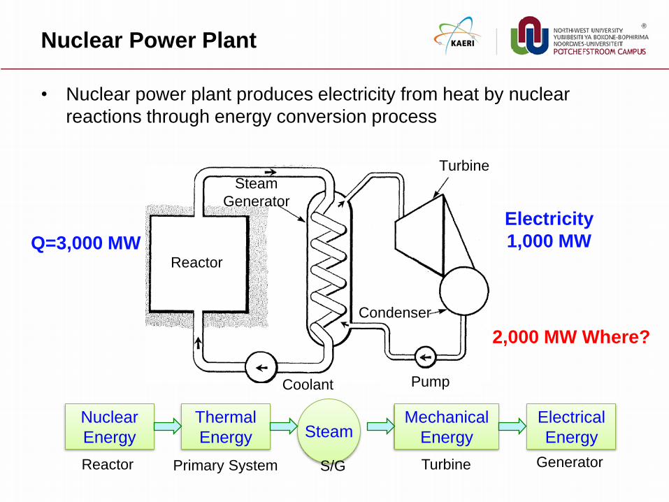
• Nuclear power plant produces electricity from heat by nuclear
reactions through energy conversion process
Nuclear
Energy
Thermal
Energy
Mechanical
Energy
Electrical
Energy Steam
Reactor Turbine S/G Primary System Generator
Reactor
Steam
Generator
Turbine
Coolant Pump
Condenser
Q=3,000 MW
Electricity
1,000 MW
2,000 MW Where?
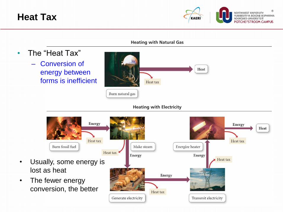
Heat Tax
• The “Heat Tax”
– Conversion of
energy between
forms is inefficient
• Usually, some energy is
lost as heat
• The fewer energy
conversion, the better

Thermodynamics
• Thermodynamics
– the study of the effects of work, heat, and energy on a system
• Important Discoveries in Thermodynamics
– Work could be converted into an equivalent amount of heat and heat
could be converted into work
Classical Thermodynamics
only concerned with macroscopic (large-scale) changes and
observations

Glossary of Terms

Temperature
• A measure of the molecular activity of a substance
– The greater the movement of molecules, the higher the temperature
– It is a relative measure of how "hot" or "cold" a substance is
– It can be used to predict the direction of heat transfer
• Measured in Fahrenheit, Celsius, and Kelvin
Cold Hot
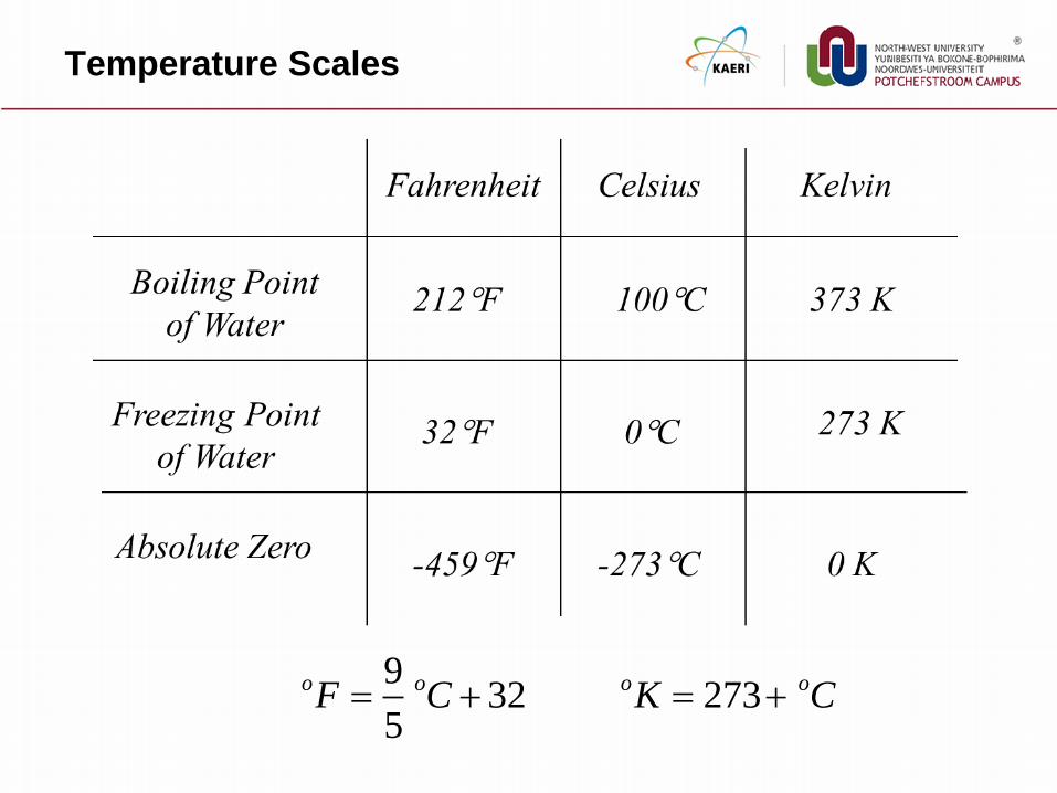
Temperature Scales
932 273
5
o o o oF C K C

Pressure
• Pressure is a measure of the force exerted per unit area on the
boundaries of a substance (or system)
– It is caused by the collisions of the molecules of the substance with the
boundaries of the system
• Units : N/m2
– Pascal, atm, bar, psi, mmHg
A
FP
F
A
Impact
Weight
abs atm gaugeP P P

Mass and Weight
• Mass (m)
– The measure of the amount of material present in that body
• Weight (wt)
– The force exerted by that body when its mass is accelerated in a
gravitational field
• Density ()
– Mass per unit volume
– units : g/cm3
V
M
High density Low density
wt mg

Volume and Specific Volume
• Volume (V)
– Volume is the quantity of three-dimensional space enclosed by some
closed boundary
– The volume of a container is generally understood to be the capacity of
the container
– Unit : m3 (cubic meter)
• Specific Volume ()
– Volume per unit Mass
– Unit : m3/kg
x
y
z
V xyz
1v

Energy
Energy (Joule)
– the capacity of a system to perform work or produce heat
• Kinetic energy : the energy of motion
• Potential energy : stored energy
– Rubber bands, Springs, Bows, Batteries, Gravitational Potential
2mv2
1KE
PE mgh

Internal Energy
• Macroscopic Forms of Energy
– Potential energy and kinetic energy
– can be visualized in terms of the position
and the velocity of objects
• Microscopic Forms of Energy
– Energy due to the rotation, vibration, translation, and interactions among
the molecules of a substance
– None of these forms of energy can be measured or evaluated directly,
but techniques have been developed to evaluate the change in the total
sum of all these microscopic forms of energy
• Internal Energy (U)
– These microscopic forms of energy are collectively called internal
energy
E U KE PE
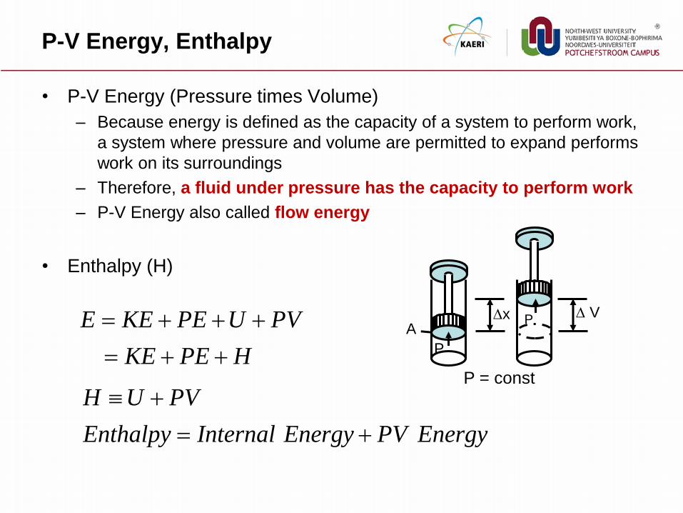
P-V Energy, Enthalpy
• P-V Energy (Pressure times Volume)
– Because energy is defined as the capacity of a system to perform work,
a system where pressure and volume are permitted to expand performs
work on its surroundings
– Therefore, a fluid under pressure has the capacity to perform work
– P-V Energy also called flow energy
• Enthalpy (H)
x
P
P A
V
P = const
E KE PE U PV
KE PE H
H U PV
Enthalpy Internal Energy PV Energy

Work
• Work (W : Joule)
– Work is a form of energy, but it is energy in transit
– Work = Force Distance
– Work is not a property of a system
– Work is a process done by or on a system, but a system contains no
work
dFW cos21
Heat
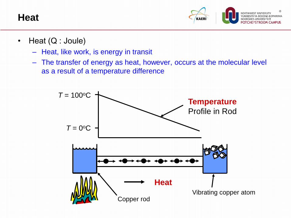
• Heat (Q : Joule)
– Heat, like work, is energy in transit
– The transfer of energy as heat, however, occurs at the molecular level
as a result of a temperature difference
Heat Vibrating copper atom
Copper rod
T = 100oC
T = 0oC
Temperature
Profile in Rod

Heat vs. Internal Energy
• Heat
– The energy that is transferred from one body or location due to a
difference in temperature
– Heat is internal energy when it is transferred between bodies
• A Hot Potato
– does not possess heat
– rather it possesses a good deal of internal energy on account of the
motion of its molecules
Hot Potato Hot potato dropped in
a bowl of cold water

Heat Capacity
• Heat Capacity (C)
– The ratio of the heat (Q) added to or removed from a substance to the
change in temperature (T) produced
– Different mediums require different amounts of energy to produce a
given temperature change
Q - heat in Joules or calories
m - mass in kilograms
DT - change the temperature in Kelvin
C has units of J/kgK or kcal/kgK
1 calorie = 4.184 Joules
Tm
QC
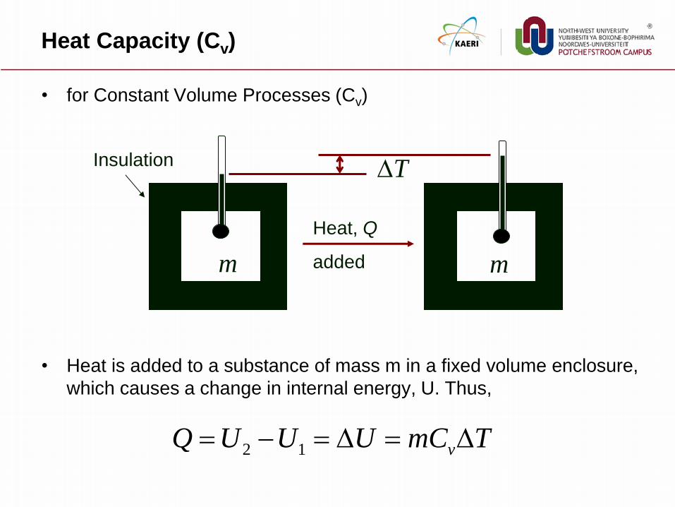
Heat Capacity (Cv)
• for Constant Volume Processes (Cv)
• Heat is added to a substance of mass m in a fixed volume enclosure,
which causes a change in internal energy, U. Thus,
Heat, Q
added m m
T Insulation
2 1 vQ U U U mC T

Heat Capacity (Cp)
• for Constant Pressure Processes (Cp)
• Heat is added to a substance of mass m held at a fixed pressure,
which causes a change in internal energy, U, AND some PV work
m Heat, Q, added
T
m
x
pQ U P V H mC T
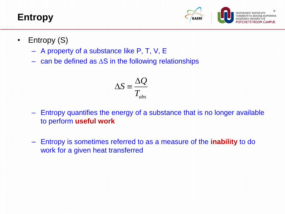
Entropy
• Entropy (S)
– A property of a substance like P, T, V, E
– can be defined as S in the following relationships
– Entropy quantifies the energy of a substance that is no longer available
to perform useful work
– Entropy is sometimes referred to as a measure of the inability to do
work for a given heat transferred
abs
QS
T

Classification of
Thermodynamic Properties
• Intensive Property
– Property which is independent of the amount of mass
– Temperature, Pressure, Density, Specific Volume
• extensive property
– Property which varies directly with the mass
– Mass, Total Volume
• It is customary to define some intensive properties associated with
extensive properties
– Specific Volume, Specific Internal Energy, Specific Enthalpy
– Intensive properties are useful because they can be
tabulated or graphed without reference to the amount of
material under study
Thermodynamic Systems and Processes
Thermodynamic System and
Surroundings
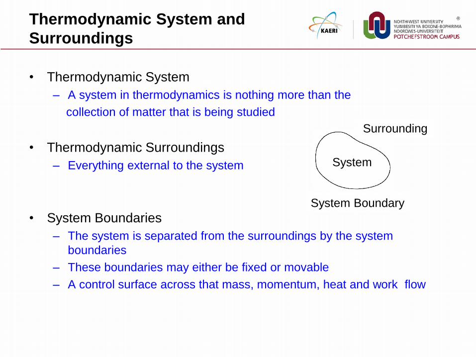
• Thermodynamic System
– A system in thermodynamics is nothing more than the
collection of matter that is being studied
• Thermodynamic Surroundings
– Everything external to the system
• System Boundaries
– The system is separated from the surroundings by the system
boundaries
– These boundaries may either be fixed or movable
– A control surface across that mass, momentum, heat and work flow
System
Surrounding
System Boundary
Types of
Thermodynamic Systems
• Isolated system
– System that is not influenced in any way by the surroundings
• No energy in the form of heat or work may cross the boundary of the system
• In addition, no mass may cross the boundary of the system
• Closed system
– System that has no transfer of mass with its surroundings,
– but may have a transfer of energy with its surroundings
• Open system
– System that may have a transfer of both mass and energy with its
surroundings
Control Volume and Control Surface
• Thermodynamic Equilibrium
– When a system is in equilibrium with regard to all possible changes in
state, the system is in thermodynamic equilibrium
• Control Volume
– A fixed region in space chosen for the thermodynamic study of mass
and energy balances for flowing systems
– The boundary of the control volume may be a real or imaginary
envelope
• Control surface : The boundary of the control volume
• Steady state
– that circumstance in which there is no accumulation of mass or energy
within the control volume, and the properties at any point within the
system are independent of time

Process and Cycle
• Thermodynamic Process
– The path of the succession of states through which the system passes is
called the thermodynamic process
• When the system changes its properties (T, P, V, etc.) from one value to
another as a consequence of work or heat or internal energy exchange, then it
is said that the fluid has gone through a "process.“
– The most common processes are those in which the temperature,
pressure, or volume is held constant during the process
• These would be classified as isothermal, isobaric, or isovolumetric processes,
respectively. Iso means "constant or one.“
• Cyclic Process or Cycle
– When a system in a given initial state goes through a number of different
changes in state (going through various processes) and finally returns to
its initial values, the system has undergone a cyclic process or cycle

Reversible Process
• Reversible Process
– A process that, once having taken place, can be reversed, and in so
doing leaves no change in either the system or surroundings
– In reality, there are no truly reversible processes. One way to make real
processes approximate reversible process is to carry out the process in
a series of small or infinitesimal steps
• Irreversible Process
– Friction, Unrestrained expansion of a fluid, Heat transfer through a finite
temperature difference, Mixing of two different substances
Not reversible unless
energy is expended
Dropping A Ball of Clay

Thermodynamic Processes
• Adiabatic process
– A process of no heat transfer into or out of the system
– When a system expands adiabatically, W is positive
– When a system compresses adiabatically, W is negative
• Isothermal process : constant temperature process
– Any heat flow into or out of the system must be slow enough to maintain
thermal equilibrium
• Isobaric process : constant pressure process
– Water boiling in a saucepan is an example of an isobar
process
• Isentropic process : constant entropy process
– This will be true if the process the system goes through is reversible and
adiabatic
Thermal Equilibrium
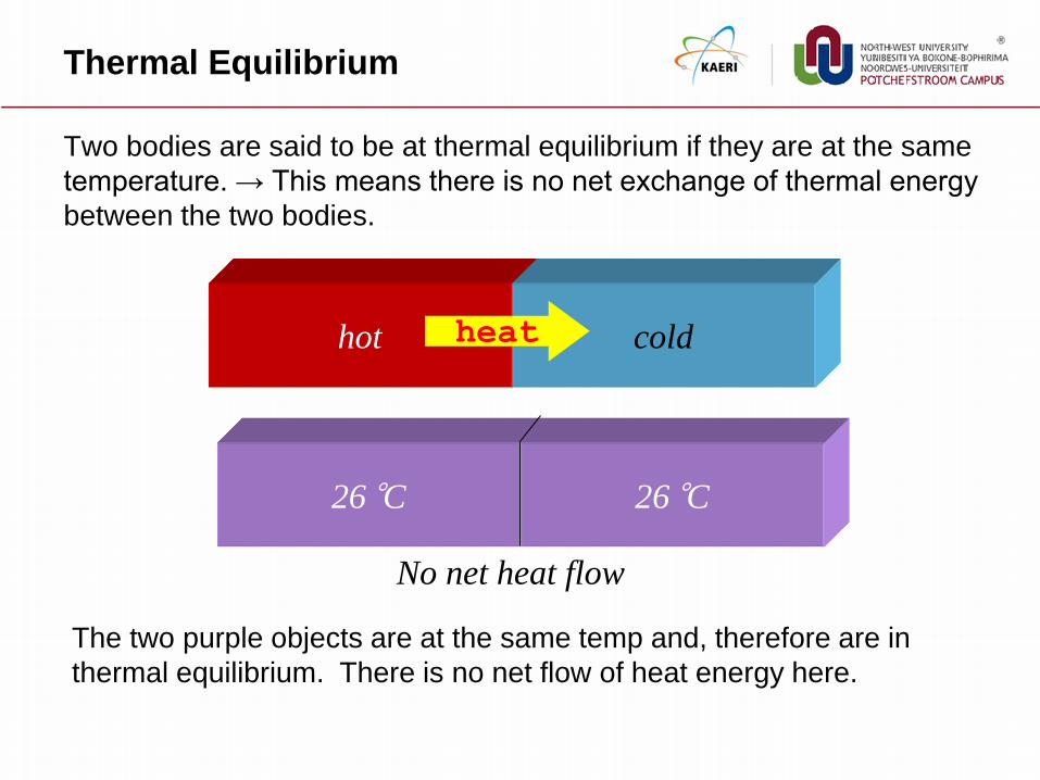
Two bodies are said to be at thermal equilibrium if they are at the same
temperature. → This means there is no net exchange of thermal energy
between the two bodies.
The two purple objects are at the same temp and, therefore are in
thermal equilibrium. There is no net flow of heat energy here.
hot cold heat
26 °C 26 °C
No net heat flow

Change of Phases

Phase Diagram (P-T Diagram)
Plasma Gas
Vapor
Liquid
Solid
Ttriple Tcritical
Ptriple
Pcritical
Pressure
Temperature
Critical
Point
Triple
Point
Boiling
Condensation
Sublimation
Melting
Freezing A point at which the density
of the liquid and vapor
phases are the same
A point at which all three phases
exist (solid, liquid and gas)

T-V Diagram
T
V
ABCD : Constant Pressure Line
(P=14.7 psia = 1 atm)
• Line AB : Sub-cooled Liquid
• Point B : Saturated Liquid
• Line BC : Saturation Line
• Point C : Saturated Vapor
• Line CD : Superheated Vapor

Saturation
• Saturation
– A condition in which a mixture of vapor and liquid can exist together at a
given temperature and pressure
– Saturation Temperature or Boiling Point
• The temperature at which boiling starts to occur for a given pressure
– Saturation Pressure
• The pressure at which boiling starts to
occur for a given temperature
• Relationship between saturation pressure and
saturation temperature
– The higher the pressure, the higher the
saturation temperature

Quality and Moisture of the Mixture
• Quality (x)
– The ratio of the mass of the vapor to the total mass of both vapor and
liquid
– Quality is an intensive property
• Moisture of The Mixture (M)
– The ratio of the mass of the liquid to the total mass of both liquid and
vapor
– The moisture content of a substance is the opposite of its quality

Property Diagrams and Steam Tables

Property Diagrams
• Property Diagram
– The phases of a substance and the relationships between its properties
are most commonly shown on property diagrams
• Basic Properties
– Pressure(P), Temperature(T), Specific Enthalpy(h), Specific Entropy(s),
Specific Volume(), Quality(x) for two phase
• Basic Property Diagrams
– P-T Diagram
– P- Diagram
– P-h Diagram
– h-T Diagram
– T-s Diagram
– h-s Diagram or Mollier Diagram

Pressure Temperature (P-T) Diagram
• The most common way to show the phases of a substance
P-T Curve for Pure Water
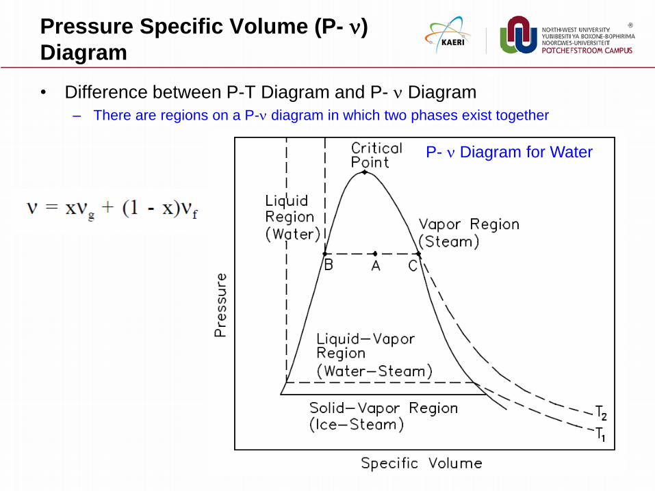
Pressure Specific Volume (P- )
Diagram
• Difference between P-T Diagram and P- Diagram
– There are regions on a P- diagram in which two phases exist together
P- Diagram for Water

Pressure Enthalpy (P-h) Diagram
• A P-h diagram exhibits the same features as a P-v diagram
P-h Diagram for Water

Enthalpy Temperature (h-T) Diagram
h-T Diagram for Water

Temperature Entropy (T-s) Diagram
• Diagram most frequently
used to analyze energy
transfer system cycles
– This is because the work done
by or on the system and the
heat added to or removed from
the system can be visualized on
the T-s diagram.
• By the definition of entropy,
the heat transferred to or
from a system equals the
area under the T-s curve of
the process
• T-s diagram exhibits the
same features as P-v
diagrams Entropy (s)
abs
QS
T
Tem
pera
ture
(T
)

Enthalpy Entropy (h-s) Diagram or
Mollier Diagram
• The Mollier diagram
– A chart on which enthalpy (h) versus
entropy (s) is plotted.
– It is sometimes known as the h-s diagram
– an entirely different shape from the T-s
diagrams.
• The chart contains
– a series of constant temperature lines
– a series of constant pressure lines
– a series of constant moisture or quality
lines
– a series of constant superheat lines
• The Mollier diagram is used only when
quality is greater than 50% and for
superheated steam
Entropy
Entropy
En
tha
lpy
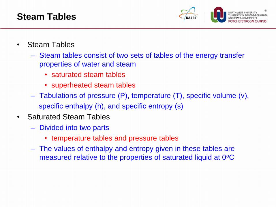
Steam Tables
• Steam Tables
– Steam tables consist of two sets of tables of the energy transfer
properties of water and steam
• saturated steam tables
• superheated steam tables
– Tabulations of pressure (P), temperature (T), specific volume (ν),
specific enthalpy (h), and specific entropy (s)
• Saturated Steam Tables
– Divided into two parts
• temperature tables and pressure tables
– The values of enthalpy and entropy given in these tables are
measured relative to the properties of saturated liquid at 0oC

Saturated Steam Table

Superheated Steam Table
Laws of Termodynamics

Laws of Thermodynamics
• Zero Law of Thermodynamics
– If: Objects A and B are the same temperature and Objects B and
C are the same temperature
– Then: Objects A and C are the same temperature
• First Law of Thermodynamics
– Energy can neither be created nor destroyed
• Second Law of Thermodynamics
– Naturally occurring processes are directional
– These processes are naturally irreversible
• Third Law of Thermodynamics
– a temperature of absolute zero is not possible

Physics
• Physics (mechanics, thermodynamics, etc.) is our model of how the
universe operates
• It is not obvious that the universe should obey the “laws” of
physics
• The laws represent the accumulated observations on the universe.
Since all observations so far indicate that physics applies, we expect
that physics to apply in all cases.
Observation
(Experiment)
General Laws
(Theory)
Analytical Solution
Numerical Solution

The Zeroth Law of Thermodynamics
When two objects are separately in thermodynamic equilibrium with a
third object, they are in equilibrium with each other
Objects in thermodynamic equilibrium have the same temperature
Thermodynamic Equilibrium

The First Law of Thermodynamics
• The First Law of Thermodynamics
– referred to as the Conservation of Energy principle
– meaning that energy can neither be created nor destroyed, but rather
transformed into various forms as the fluid within the control volume is
being studied
• Energy Balance
in outE E Q W
W Q
System Boundary
inE out
E
E Q W
Internal Energy

Experiment (Joule)
• Cyclic Process of A Control Mass
• Observation
Q W Gas Gas
WQ

Internal Energy
P
V
1
2 A
B
C
2
1
2
1
)()( CA WQWQ
1
2
2
1
1
2
2
1
BABA WWQQ
A cycle of Path A and B
1
2
2
1
1
2
2
1
BCBC WWQQ
2 2 2 2
1 1 1 1
A C A CQ Q W W
A cycle of Path C and B
dE Q W

The First Law of Thermodynamics
• Any thermodynamic system in an equilibrium state possesses a
state variable called the internal energy (E)
• Between two equilibrium states, the change in internal energy is
equal to the difference of the heat transfer into the system and work
done by the system

The Second Law of Thermodynamics
• The Second Law of Thermodynamics : by R. Clausius
– It is impossible to construct a device that operates in a cycle and
produces no effect other than the removal of heat from a body at
one temperature and the absorption of an equal quantity of heat by
a body at a higher temperature
• The Second Law of Thermodynamics : by Max Planck
– It is impossible to construct an engine that will work in a complete
cycle and produce no other effect except the raising of a weight and
the cooling of a heat reservoir

Observation
• Work into Heat
– work may be converted to heat completely
• Heat into Work
– Heat cannot be converted to work completely
• The first law of thermodynamics can not provide any information
about the direction of the process
Q
W Gas
Gas

Direction of Spontaneous Process
Final State
Sucrose dissolves
(heat given off to surroundings)
Initial State Process
Heat flows
between blocks
Ice melts
(heat flows from water)
Cards shuffled
Partition removed
Water evaporates
(heat flows from dish)

Second Law of Thermodynamics
• There exists a useful thermodynamic variable called entropy (S). A
natural process that starts in one equilibrium state and ends in another
will go in the direction that causes the entropy of the system plus the
environment to increase
Sf = Si (reversible) Sf > Si (irreversible)

Entropy
• The second law of thermodynamics introduces the notion of entropy
(S), a measure of system disorder (messiness)
• Internal Energy (U) is the quantity of a system’s energy, Entropy (S)
is the quality of a system’s energy
• C.P. Snow :
– not knowing the 2nd law of thermodynamics is the cultural
equivalent to never having read Shakespeare

Heat Engine
• The Second Law of Thermodynamics : by Max Planck
– It is impossible to construct an engine that will work in a
complete cycle and produce no other effect except the raising of
a weight and the cooling of a heat reservoir
• Heat Engine
– A system that performs the
conversion of heat or thermal
energy to mechanical work
Heat
Engine
High Temperature reservoir
Low Temperature reservoir
1H C C
hot H H
Q Q QWEfficiency
Q Q Q

Carnot’s Principle
• Question
– What’s the maximum efficiency such a heat engine can be?
• Carnot’s Principle
– No engine can be more efficient than a reversible engine
operating between the same high temperature and low
temperature reservoirs
– The efficiencies of all reversible engines operating between the same
constant temperature reservoirs are the same
– The efficiency of a reversible engine depends only upon the
temperatures of the heat source and heat receiver
Carnot's Cycle Efficiency 1 1C C
H H
Q T
Q T

Carnot Cycle
• Process 1-2
– Adiabatic compression from TC to TH due to
work performed on fluid
• Process 2-3
– Isothermal expansion as fluid expands
when heat is added to the fluid at
temperature TH
• Process 3-4
– Adiabatic expansion as the fluid performs work
during the expansion process and temperature
drops from TH to TC
• Process 4-1
– Isothermal compression as the fluid contracts
when heat is removed from the fluid at
temperature TC

The Third Law of Thermodynamics
• No system can reach absolute zero
• This is one reason we use the Kelvin temperature
scale. Not only is the internal energy proportional to
temperature, but you never have to worry about
dividing by zero in an equation!
• There is no formula associated with the 3rd law of thermodynamics
Carnot's Cycle Efficiency 1 1C C
H H
Q T
Q T

Steam Power Cycle
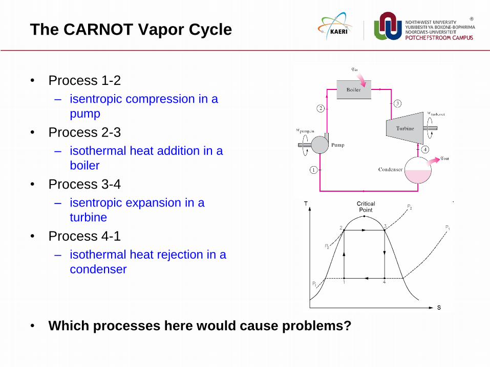
The CARNOT Vapor Cycle
• Process 1-2
– isentropic compression in a
pump
• Process 2-3
– isothermal heat addition in a
boiler
• Process 3-4
– isentropic expansion in a
turbine
• Process 4-1
– isothermal heat rejection in a
condenser
• Which processes here would cause problems?
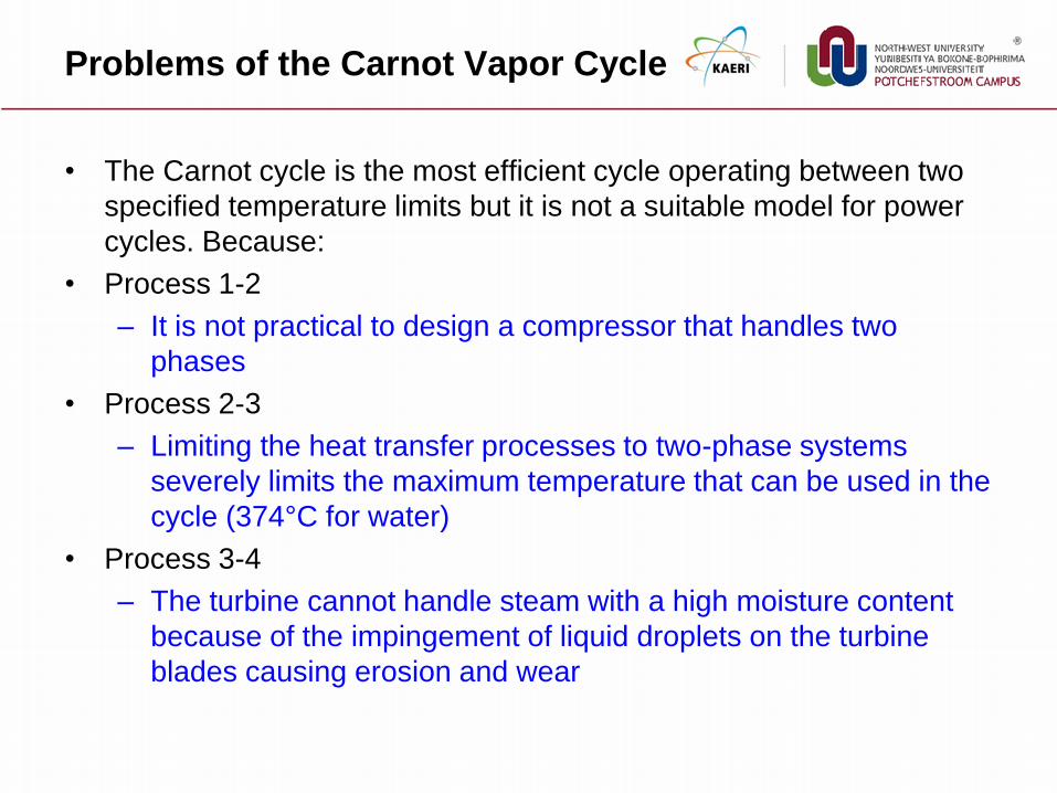
Problems of the Carnot Vapor Cycle
• The Carnot cycle is the most efficient cycle operating between two
specified temperature limits but it is not a suitable model for power
cycles. Because:
• Process 1-2
– It is not practical to design a compressor that handles two
phases
• Process 2-3
– Limiting the heat transfer processes to two-phase systems
severely limits the maximum temperature that can be used in the
cycle (374°C for water)
• Process 3-4
– The turbine cannot handle steam with a high moisture content
because of the impingement of liquid droplets on the turbine
blades causing erosion and wear

Ideal Rankine Cycle
• This cycle follows the idea of the Carnot cycle but can be practically
implemented
• Process 1-2
– isentropic pump
• Process 2-3
– constant pressure heat
addition
• Process 3-4
– isentropic turbine
• Process 4-1
– Constant pressure heat
rejection

Energy Analysis of
the Ideal Rankine Cycle
Steady-flow energy equation
The thermal efficiency can be interpreted as
the ratio of the area enclosed by the cycle on a
T-s diagram to the area under the heat-addition
process.
( ) ( ) (kJ/kg)in out in out e iq q w w h h
pump in 2 1 2 1
1 1
( 0) : ( )
@ , @f f
Pump q w h h v P P
h h P v v v P
3 2
3 4
4 1
( 0) :
( 0) :
( 0) :
in
turbine
out
Boiler w q h h
Turbine q w h h
Condenser w q h h
1
net in out turbine pump in
net outth
in in
w q q w w
w q
q q

Deviations from Ideal in Real Cycles
• The actual vapor power cycle differs from the ideal Rankine cycle as
a result of irreversibilities in various components.
• Fluid friction and heat loss to the surroundings are the two common
sources of irreversibilities
2 1
2 1
s sp
a a
w h h
w h h
3 4
3 4
a at
s s
w h h
w h h

Thermal Efficiency of Power Cycle
• The basic idea behind all the modifications to increase the thermal
efficiency of a power cycle
– Increase the average temperature at which heat is transferred to the
working fluid in the boiler, or
– Decrease the average temperature at which heat is rejected from the
working fluid in the condenser
• Way of increasing thermal efficiency
– Lower condenser pressure
– Superheat the steam more
– Increase boiler pressure (with same Tmax)
– Reheat Cycle
– Regeneration Cycle

Lowering the Condenser Pressure
• To take advantage of the
increased efficiencies at low
pressures, the condensers of
steam power plants usually
operate well below the
atmospheric pressure
• There is a lower limit to this
pressure depending on the
temperature of the cooling
medium
• Side effect: Lowering the condenser pressure increases the
moisture content of the steam at the final stages of the turbine

Superheating the Steam
to High Temperature
• Both the net work and heat input
increase as a result of superheating
the steam to a higher temperature
• The overall effect is an increase in
thermal efficiency since the average
temperature at which heat is added
increases
• Both the net work and heat input increase as a result of Superheating to higher temperatures decreases the moisture content of
the steam at the turbine exit, which is desirable
• The temperature is limited by metallurgical considerations.
Presently the highest steam temperature allowed at the turbine
inlet is about 620°C.

Increasing the Boiler Pressure
• The net work increases as a
result of increasing the boiler
pressure
• The overall effect is an increase
in thermal efficiency since the
average temperature at which
heat is added increases
• For a fixed turbine inlet temperature, the cycle shifts to the left and
the moisture content of steam at the turbine exit increases. This side
effect can be corrected by reheating the steam.

Supercritical Power Plant
• Today many modern steam
power plants operate at
supercritical pressures (P >
22.06 MPa) and have thermal
efficiencies of about 40% for
fossil-fuel plants

Reheat Rankine Cycle
• How can we take advantage of the increased efficiencies at higher
boiler pressures without facing the problem of excessive moisture at
the final stages of the turbine?
– Superheat the steam to very high temperatures
– Expand the steam in the turbine in two stages, and reheat it in between

Evaluation of Reheat Rankine Cycle
• The single reheat in a modern power plant improves the cycle
efficiency by 4 to 5% by increasing the average temperature at
which heat is transferred to the steam
– The use of more than two reheat stages is not practical
– The theoretical improvement in efficiency from the second reheat is
about half of that which results from a single reheat
• Reheat Cycle Design
– The reheat temperatures are very close or equal to the turbine inlet
temperature
– The optimum reheat pressure is about one-fourth of the maximum cycle
pressure

The Ideal Regenerative Rankine Cycle
• Heat is transferred to the working
fluid during process 2-2’ at a
relatively low temperature
• This lowers the average heat-
addition temperature and thus the
cycle efficiency
• In steam power plants, steam is extracted from the turbine at
various points. This steam, which could have produced more work
by expanding further in the turbine, is used to heat the feedwater
instead.
• The device where the feedwater is heated by regeneration is
called a regenerator, or a feedwater heater (FWH)

Regenerative Rankine cycle with
an open feedwater heater
• An open (or direct-contact) feedwater heater is basically a mixing
chamber, where the steam extracted from the turbine mixes with the
feedwater exiting the pump
• Ideally, the mixture leaves the heater as a saturated liquid at the
heater pressure
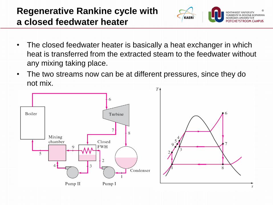
Regenerative Rankine cycle with
a closed feedwater heater
• The closed feedwater heater is basically a heat exchanger in which
heat is transferred from the extracted steam to the feedwater without
any mixing taking place.
• The two streams now can be at different pressures, since they do
not mix.

Open and Closed Feedwater Heaters
• The closed feedwater heaters
– more complex because of the internal tubing network, and thus they are
more expensive.
– Heat transfer in closed feedwater heaters is less effective since the two
streams are not allowed to be in direct contact.
– However, closed feedwater heaters do not require a separate pump for
each heater since the extracted steam and the feedwater can be at
different pressures.
• Open feedwater heaters
– simple and inexpensive and have good heat transfer characteristics
– For each heater, however, a pump is required to handle the feedwater
• Most steam power plants use a combination of open and closed
feedwater heaters
steam
Feed water
steam generator
HP turbine LP turbine G
moisture separator
reheater
steam
LP extracted steam
Deaerater
steam
condensate pump
condenser
LP extracted steam
feedwater pump HP extracted steam
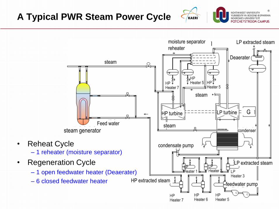
A Typical PWR Steam Power Cycle
• Reheat Cycle – 1 reheater (moisture separator)
• Regeneration Cycle
– 1 open feedwater heater (Deaerater)
– 6 closed feedwater heater

Thank you