thermo scientific dionex ultimate 3000...
TRANSCRIPT
Thermo Scientific Dionex UltiMate 3000 Series
WPS-3000 Autosamplers (SL, TBSL, RS, TBRS, TXRS)
Operating Instructions (Original Operating Instructions)
Revision: 1.8 Date: September 2013
© 2013 Thermo Fisher Scientific Doc.-No. 4828.2250

UltiMate 3000 Series: WPS-3000 Autosamplers (SL, TBSL, RS, TBRS, TXRS)
Operating Instructions
UltiMate 3000 Series: WPS-3000 Autosamplers (SL, TBSL, RS, TBRS, TXRS)
Operating Instructions Page I
Declaration of Conformity (Original Declaration of Conformity)
Product: Thermo Scientific Dionex UltiMate 3000 - Autosampler
Types: WPS-3000SL and WPS-3000T(B)SL WPS-3000RS, WPS-3000T(B)RS, and WPS-3000TXRS
Dionex Softron GmbH herewith declares conformity of the above products with the respective requirements of the following regulations:
• Low-Voltage Directive 2006/95/EC • EMC Directive 2004/108/EC
The electrical safety of the products was evaluated based on the following standard:
• DIN EN 61010-1:2010 Safety requirements for electrical equipment for measurement, control and laboratory use, Part 1: General Requirements
The Electromagnetic Compatibility (EMC) of the products was evaluated based on the following standard:
• DIN EN 61326:2006 Electrical equipment for measurement, control and laboratory use EMC Requirements
This declaration is issued for the manufacturer
Dionex Softron GmbH Part of Thermo Fisher Scientific Inc. Dornierstraße 4 D-82110 Germering
by the Managing Director, Rüdiger Obst and the Vice President HPLC, Fraser McLeod.
September 2, 2013

UltiMate 3000 Series: WPS-3000 Autosamplers (SL, TBSL, RS, TBRS, TXRS)
Page II Operating Instructions
UltiMate 3000 Series: WPS-3000 Autosamplers (SL, TBSL, RS, TBRS, TXRS)
Operating Instructions Page i
Table of Contents 1 Introduction ................................................................................................................... 1
1.1 How to Use This Manual ........................................................................................... 1 1.2 Safety Information ..................................................................................................... 3
1.2.1 Symbols on the Autosampler and in the Manual ............................................... 3 1.2.2 Safety Precautions .............................................................................................. 5 1.2.3 Consignes Générales de Sécurité ....................................................................... 8
1.3 Intended Use ............................................................................................................ 12 1.4 Federal Communications Commission (FCC) Note ................................................ 13
2 Overview ...................................................................................................................... 15
2.1 Unit Description ....................................................................................................... 15 2.2 Operating Principle .................................................................................................. 16 2.3 Autosampler Configurations .................................................................................... 18
2.3.1 Overview .......................................................................................................... 18 2.3.2 Autosampler with Sample Thermostatting Option .......................................... 20 2.3.3 Proper Syringe, Buffer Loop and Sample Loop Combinations ....................... 21
2.4 Interior Components ................................................................................................ 22 2.5 Front Panel Elements ............................................................................................... 24 2.6 Rear Panel ................................................................................................................ 25
2.6.1 Power Switch ................................................................................................... 26 2.6.2 Fuse Cartridge .................................................................................................. 26 2.6.3 USB Port (USB 1.1) ......................................................................................... 26 2.6.4 Digital I/O Ports ............................................................................................... 27
2.7 Carousel, Sample Racks, Vials, and Well Plates ..................................................... 28 2.8 Compartment Lights ................................................................................................ 30 2.9 Fluid Connections .................................................................................................... 31 2.10 Leak Sensor .............................................................................................................. 31 2.11 Injection Valve ......................................................................................................... 32 2.12 Chromeleon Software .............................................................................................. 33 2.13 System Wellness, Predictive Performance, and Diagnostics ................................... 34
3 Installation ................................................................................................................... 35
3.1 Facility Requirements .............................................................................................. 35 3.2 Unpacking ................................................................................................................ 36 3.3 Positioning the Autosampler in the UltiMate 3000 System .................................... 38 3.4 Connecting the Autosampler ................................................................................... 40
3.4.1 General Information ......................................................................................... 40 3.4.2 Connecting the USB Cable .............................................................................. 40 3.4.3 Connecting the Power Cord ............................................................................. 41 3.4.4 Connecting the Digital I/O ............................................................................... 41
UltiMate 3000 Series: WPS-3000 Autosamplers (SL, TBSL, RS, TBRS, TXRS)
Page ii Operating Instructions
3.5 Setting Up the Autosampler in Chromeleon ............................................................ 42 3.5.1 Loading the USB Driver for the Autosampler ................................................. 42 3.5.2 Installing the Autosampler ............................................................................... 44 3.5.3 Configuring the Autosampler ........................................................................... 45
3.6 Setting Up the Autosampler in DCMSLink ............................................................. 51
4 Preparation for Operation (Startup) ........................................................................ 53
4.1 Overview of Actions ................................................................................................ 53 4.2 Tips and Precautions for Connecting Capillaries ..................................................... 54 4.3 Connecting the Wash Liquid Lines .......................................................................... 56
4.3.1 Connecting the Wash Liquid Lines for Online Degassing .............................. 56 4.3.2 Connecting the Wash Liquid Bottle ................................................................. 58
4.4 Connections on the Syringe Valve ........................................................................... 59 4.5 Connecting Drain Tubing......................................................................................... 60 4.6 Removing Air Bubbles from the Syringe (Priming) ................................................ 60 4.7 Installing and Loading the Sample Rack ................................................................. 62 4.8 Loading the 5-Position Vial Holder ......................................................................... 64 4.9 Equilibrating the System .......................................................................................... 65
5 Operation and Maintenance ...................................................................................... 67
5.1 Power-Up ................................................................................................................. 67 5.2 Status Screen ............................................................................................................ 68 5.3 Sample Positions ...................................................................................................... 69 5.4 Operating the Autosampler from Chromeleon ......................................................... 71
5.4.1 Connecting to Chromeleon .............................................................................. 71 5.4.2 Direct Control .................................................................................................. 72 5.4.3 Automated Control ........................................................................................... 75
5.5 Display Screens (Function Keys and Menus) .......................................................... 77 5.5.1 Showing the Function Keys ............................................................................. 77 5.5.2 Autosampler Menus ......................................................................................... 78
5.6 Settings for Operating the Autosampler................................................................... 84 5.6.1 Linking the Autosampler to the Pump ............................................................. 84 5.6.2 Synchronizing the Inject Command with the Pump Strokes ........................... 85 5.6.3 Turning On Sample Thermostatting ................................................................ 86 5.6.4 Changing the Carousel Configuration .............................................................. 87 5.6.5 Setting the Injection Parameters and Starting the Injection ............................. 87 5.6.6 Detecting Liquid Leaks .................................................................................... 89 5.6.7 Adjusting the Screen Brightness or Contrast ................................................... 89 5.6.8 SmartStartup and SmartShutdown ................................................................... 90 5.6.9 Recommendations for Operation ..................................................................... 90
5.7 Special Chromeleon Functions ................................................................................ 91 5.7.1 Predictive Performance .................................................................................... 91 5.7.2 Autosampler Diagnostics ................................................................................. 92 5.7.3 Defining the Needle Height (SampleHeight, ReagentLiquidHeight) .............. 93 5.7.4 Moving the Tray before Drawing the Sample (Tray Shake) ........................... 95
UltiMate 3000 Series: WPS-3000 Autosamplers (SL, TBSL, RS, TBRS, TXRS)
Operating Instructions Page iii
5.7.5 Venting the Vial ............................................................................................... 95 5.7.6 Operational Qualification and Performance Qualification .............................. 95 5.7.7 Automatic Tray Test ........................................................................................ 95 5.7.8 Automatic Sample Container Detection .......................................................... 96 5.7.9 User-Defined Programs ................................................................................... 97
5.8 Shutting Down the Autosampler.............................................................................. 99 5.9 Routine and Preventive Maintenance .................................................................... 101
6 Troubleshooting ........................................................................................................ 103
6.1 Overview ................................................................................................................ 103 6.2 Messages on the Autosampler Display .................................................................. 104 6.3 Chromeleon Diagnostics Messages ....................................................................... 110 6.4 Operating Problems ............................................................................................... 112
7 Service ........................................................................................................................ 117
7.1 General Notes and Safety Precautions ................................................................... 117 7.2 Eliminating Leakage .............................................................................................. 119 7.3 Replacing the Syringe ............................................................................................ 120 7.4 Replacing the Buffer Loop .................................................................................... 123 7.5 Needle .................................................................................................................... 124
7.5.1 Replacing the Needle ..................................................................................... 124 7.5.2 Washing the Needle ....................................................................................... 129
7.6 Replacing the Sample Loop ................................................................................... 130 7.6.1 WPS-3000SL Analytical, WPS-3000RS/TBRS/TXRS ................................. 130 7.6.2 WPS-3000TBSL Analytical .......................................................................... 133 7.6.3 WPS-3000SL Semiprep ................................................................................. 135
7.7 Needle Seat ............................................................................................................ 138 7.7.1 Replacing the Needle Seat ............................................................................. 138 7.7.2 Replacing the Needle Seat Capillary ............................................................. 141
7.8 Injection Valve ....................................................................................................... 147 7.8.1 Inspecting the Injection Valve for Leakage ................................................... 148 7.8.2 Replacing the Valve Pod ................................................................................ 149 7.8.3 Replacing the Valve Stator ............................................................................ 153 7.8.4 Rotor Seal and Stator Face Seal ..................................................................... 154
7.9 Replacing the Main Power Fuses........................................................................... 157 7.10 Updating the Autosampler Firmware .................................................................... 158
8 Optimizing for Special Applications ....................................................................... 161
9 Technical Information .............................................................................................. 163
9.1 WPS-3000SL Analytical and WPS-3000SL Semiprep ......................................... 163 9.2 WPS-3000TBSL Analytical .................................................................................. 165 9.3 WPS-3000RS ......................................................................................................... 167 9.4 WPS-3000TBRS .................................................................................................... 169 9.5 WPS-3000TXRS .................................................................................................... 171
UltiMate 3000 Series: WPS-3000 Autosamplers (SL, TBSL, RS, TBRS, TXRS)
Page iv Operating Instructions
10 Accessories, Spare Parts, and Consumables........................................................... 173
10.1 Standard Accessories ............................................................................................. 173 10.2 Optional Accessories.............................................................................................. 177 10.3 Consumables and Spare Parts ................................................................................ 182
11 Appendix - Digital I/O (Pin Assignment) ................................................................ 191
12 Index ........................................................................................................................... 193

UltiMate 3000 Series: WPS-3000 Autosamplers (SL, TBSL, RS, TBRS, TXRS)
Operating Instructions Page 1
1 Introduction
1.1 How to Use This Manual
The layout of this manual is designed to provide quick reference to the sections of interest to the reader. However, in order to obtain a full understanding of your Thermo Scientific™ Dionex™ WPS-3000 autosampler, Thermo Fisher Scientific recommends that you review the manual thoroughly before beginning operation.
The descriptions in this manual apply to the following autosamplers in the UltiMate™ 3000 autosampler series:
• WPS-3000(T)SL Analytical and WPS-3000(T)SL Semiprep
• WPS-3000TBSL Analytical
• WPS-3000(T)RS
• WPS-3000TBRS
• WPS-3000TXRS
The following conventions apply to the descriptions throughout this manual:
• The term "the device" or "the autosampler" is used throughout the manual. If some detail applies to only one autosampler model or one version, the model or version is identified by name.
• If not otherwise stated, the descriptions for the
♦ WPS-3000SL Analytical, WPS-3000SL Semiprep, and WPS-3000RS autosamplers apply also to the versions with sample thermostatting option (WPS-3000TSL Analytical, WPS-3000TSL Semiprep, and WPS-3000TRS).
♦ Viper™ capillary connections apply also to nanoViper™ and possible other Viper capillary connections.
• The device configuration may vary, for example, the autosampler may have a thermostatted carousel. Therefore, not all descriptions necessarily apply to your particular instrument.
• The representation of a component in this manual may be different from the real component. However, this does not influence the descriptions.
• The descriptions in this manual refer to firmware version 4.13 and Chromeleon™ 6.80 Service Release 13. If you want to operate the autosampler from Chromeleon 7, note the information on page 33.
UltiMate 3000 Series: WPS-3000 Autosamplers (SL, TBSL, RS, TBRS, TXRS)
Page 2 Operating Instructions
This manual is provided "as is". Every effort has been made to supply complete and accurate information and all technical specifications have been developed with the utmost care. The information contained in this manual should not be construed as a commitment by Thermo Fisher Scientific. Thermo Fisher Scientific assumes no responsibility for any errors that may appear in this document that is believed to be complete and accurate at the time of publication and, in no event, shall Thermo Fisher Scientific be liable for incidental or consequential damages in connection with or arising from the use of this document. We appreciate your help in eliminating any errors that may appear in this document.
The information contained in this document is subject to change without notice.
All rights reserved, including those for photomechanical reproduction and storage on electronic media. No part of this publication may be copied or distributed, transmitted, transcribed, stored in a retrieval system, or transmitted into any human or computer language, in any form or by any means, electronic, mechanical, magnetic, manual, or otherwise, or disclosed to third parties without the express written permission of Thermo Fisher Scientific Inc.
Trademarks Analyst is a registered trademark of AB Sciex. Compass and Hystar are trademarks of Bruker Daltonics. Empower is a trademark of Waters Corp. MP35N is a registered trademark of SPS Technologies. PEEK is a trademark of Victrex PLC. Vespel is a registered trademark of E.I. du Pont de Nemours & Company. Microsoft, Windows, and Windows Vista are registered trademarks of Microsoft Corp. All other trademarks are property of Thermo Fisher Scientific Inc. and its subsidiaries.
UltiMate 3000 Series: WPS-3000 Autosamplers (SL, TBSL, RS, TBRS, TXRS)
Operating Instructions Page 3
1.2 Safety Information
The CE Mark and cTUVus labels on the instrument indicate that the instrument is compliant with the related standards.
1.2.1 Symbols on the Autosampler and in the Manual
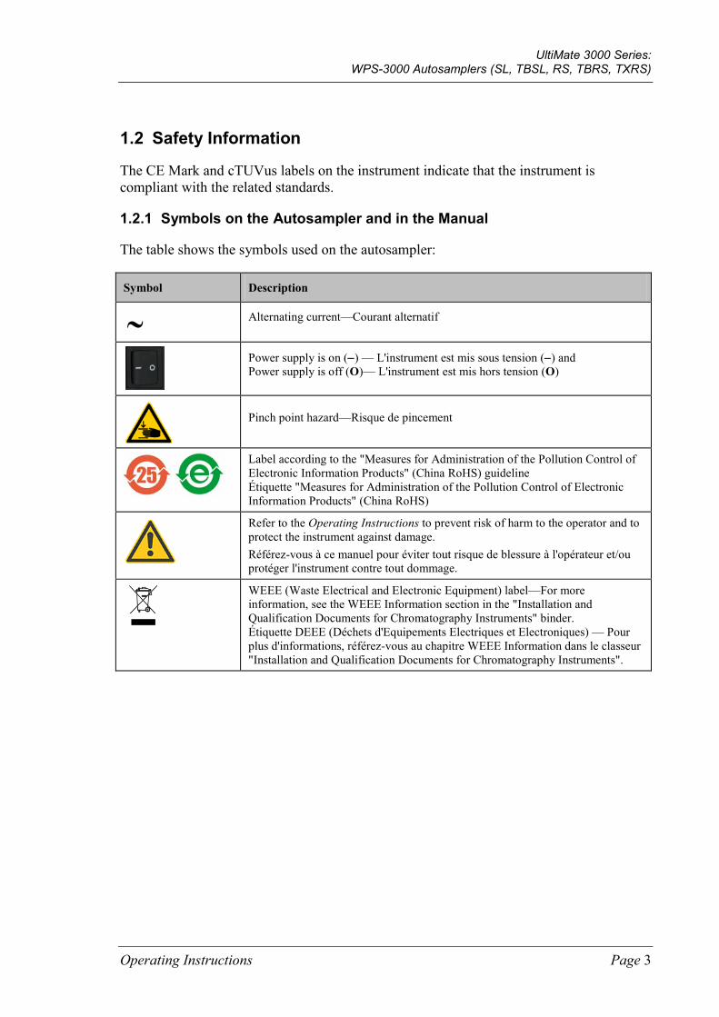
The table shows the symbols used on the autosampler:
Symbol Description
Alternating current—Courant alternatif
Power supply is on (−) — L'instrument est mis sous tension (−) and Power supply is off (O)— L'instrument est mis hors tension (O)
Pinch point hazard—Risque de pincement
Label according to the "Measures for Administration of the Pollution Control of Electronic Information Products" (China RoHS) guideline Étiquette "Measures for Administration of the Pollution Control of Electronic Information Products" (China RoHS)
Refer to the Operating Instructions to prevent risk of harm to the operator and to protect the instrument against damage. Référez-vous à ce manuel pour éviter tout risque de blessure à l'opérateur et/ou protéger l'instrument contre tout dommage.
WEEE (Waste Electrical and Electronic Equipment) label—For more information, see the WEEE Information section in the "Installation and Qualification Documents for Chromatography Instruments" binder. Étiquette DEEE (Déchets d'Equipements Electriques et Electroniques) — Pour plus d'informations, référez-vous au chapitre WEEE Information dans le classeur "Installation and Qualification Documents for Chromatography Instruments".
˜
UltiMate 3000 Series: WPS-3000 Autosamplers (SL, TBSL, RS, TBRS, TXRS)
Page 4 Operating Instructions
At various points throughout the manual, the following symbols indicate messages of particular importance:
Tip: Indicates general information, as well as information intended to optimize the performance of the instrument.
Important: Indicates that failure to take note of the accompanying information could cause wrong results or may result in damage to the instrument.
Important: Indique que ne pas tenir compte de l'information jointe peut conduire à de faux résultat ou endommager l'instrument.
Warning: Indicates that failure to take note of the accompanying information may result in personal injury.
Avertissement: Indique que ne pas tenir compte de l'information jointe peut entraîner des blessures corporelles.
UltiMate 3000 Series: WPS-3000 Autosamplers (SL, TBSL, RS, TBRS, TXRS)
Operating Instructions Page 5
1.2.2 Safety Precautions
When working with analytical instrumentation, you must know the potential hazards of using chemical solvents.
Tips: Before initial operation of the autosampler, make yourself familiar with the contents of this manual.
For the safety precautions in French, see page 8.
Warning: All users of the device must observe the following safety precautions and all additional safety precautions in this manual to avoid the possibility of personal injury or damage to the device when operating the device or carrying out any maintenance or service procedures.
Observe any warning labels on the autosampler and see the related sections in these Operating Instructions.
• Protective equipment When performing any work on or near the HPLC system, wear personal protective equipment (protective clothing, safety gloves, safety glasses) as required by the hazard of the mobile phase and sample. For information about the proper handling of a particular substance and for advice on specific hazards, refer to the material safety data sheet for the substance you are using. Observe the guidelines of Good Laboratory Practice (GLP).
An eyewash facility and a sink should be close to the device. If any substance splashes on the eyes or skin, wash the affected area and seek medical attention.
• Hazardous substances Many organic solvents, mobile phases, and samples are harmful to health. Be sure that you know the toxic and infectious properties of all substances that you are using. You may not know the toxic or infectious properties of many substances that you are using. If you have any doubt about a substance, treat it as if it contains a potentially harmful substance. For advice on the proper handling of a particular substance, refer to the Safety Data Sheet (SDS) of the manufacturer. Observe the guidelines of Good Laboratory Practice (GLP).
Dispose of waste substance in an environmentally safe manner that is consistent with all local regulations. Do not allow flammable, toxic, and/or infectious substances to accumulate. Follow a regulated, approved waste disposal program. Never dispose of flammable, toxic, and/or infectious substances through the municipal sewage system.
• Hazardous gases Install the HPLC system in a well-ventilated laboratory. If the mobile phase or sample includes volatile or flammable solvents, do not allow them to enter the workspace. If the mobile phase or sample includes volatile or flammable solvents, avoid open flames and sparks.
UltiMate 3000 Series: WPS-3000 Autosamplers (SL, TBSL, RS, TBRS, TXRS)
Page 6 Operating Instructions
• Electrostatic discharge Discharge of electrostatic energy may lead to sparking and can constitute a fire hazard. Keep in mind that liquid flowing through capillaries can generate static electricity. This effect is particularly pronounced in insulating capillaries and with non-conductive solvents (for example, pure acetonitrile).
Take appropriate measures to prevent the generation of static electricity near the HPLC system. For example, make sure that the air humidity level in the laboratory is sufficiently high and provide proper ventilation, wear anti-static clothing or shoes, prevent accumulation of air bubbles in waste lines, and use grounded waste containers. Use only non-conductive capillaries to direct solvents into the waste container. With electrically conductive capillaries, make sure that they are properly grounded.
• Self-ignition of solvents Do not use solvents for which the self-ignition temperature is below 150 °C. In case of leakage, these solvents may self-ignite on a hot surface.
• Capillaries, capillary connections, open connections ♦ Capillaries, especially non-metallic capillaries may burst, slip out of their fittings or
may not be screwed in. This may result in substances spraying out of the open connections.
♦ In an UltiMate 3000 system, some components are made of PEEK™. This polymer has superb chemical resistance to most organic solvents. However, it tends to swell when in contact with trichlormethane (CHCl3), dimethyl sulfoxide (DMSO), or tetrahydrofuran (THF). In addition, it is attacked by concentrated acids, such as, sulfuric acid and nitric acid or a mixture of hexane, ethyl acetate, and methanol. In both cases, capillaries may start leaking or they can burst. Swelling or attack by concentrated acids is not a problem with brief flushing procedures.
♦ Do not use tubing that is stressed, bent, kinked, or damaged.
♦ Capillary connections can be contaminated by harmful substances or harmful substances can escape from open connections.
♦ In an UltiMate 3000 Bio RS system, some Viper system capillaries are made of MP35N®, a nickel-cobalt based alloy. Individuals with sensitivity to nickel/cobalt may show an allergic reaction from skin contact.
♦ Always wear safety glasses when handling fused silica tubing, for example, during installation or when cutting capillaries to the length.
• Disconnect the device from all power sources before removing the panels. When the panels are removed, dangerous electrical connections will be exposed. The enclosure must be opened only by Thermo Fisher Scientific service personnel.
• Replace faulty communication cables.
• Replace faulty power cords. Never use a power cord other than the power cords provided for the device.
UltiMate 3000 Series: WPS-3000 Autosamplers (SL, TBSL, RS, TBRS, TXRS)
Operating Instructions Page 7
• Always replace blown fuses with original spare part fuses authorized by Thermo Fisher Scientific.
• Use only the original spare parts and accessories authorized for the device by Thermo Fisher Scientific.
• Avoid looking directly into the sample compartment light LED. Do not use light focusing instruments for viewing the light beam. The high luminosity of the lamp can be harmful to the eyes.
• The autosampler is primed with 2-propanol. During initial operation of the autosampler, make sure that the solvents used are miscible with 2-propanol. Otherwise, follow the appropriate intermediate steps.
• A team effort is required to lift or move the autosampler. The autosampler is too heavy and/or bulky for one person alone to lift or move safely.
• When lifting or moving the autosampler, always lift by the bottom or sides of the unit, with the front panel being closed. This is to avoid damage to the instrument.
• The front panel tilts upward. The open front panel door is not designed to carry weight. Do not place any objects on the open door.
• To avoid personal injury, do not reach inside the sample compartment during a running analysis.
• Use only standard solvents (minimum HPLC grade) and buffers that are compatible with all parts that may be exposed to solvents.
• If a leak occurs, turn off the instrument and remedy the situation immediately.
• Before interrupting operation for several days or more or when preparing the autosampler for transport, observe the precautions for shutting down the instrument (→ page 99).
• Do not use the autosampler in ways other than those described in this manual.
• Keep the operating instructions near the device to be available for quick reference.
UltiMate 3000 Series: WPS-3000 Autosamplers (SL, TBSL, RS, TBRS, TXRS)
Page 8 Operating Instructions
1.2.3 Consignes Générales de Sécurité
Si vous utilisez d'instrumentation analytique, vous devez connaître les risques d'utilisation de produit chimiques.
Veuillez noter: Avant de commencer à utiliser l'instrument, assurez-vous que vous vous êtes familiarisés avec le contenu de ce manuel.
Avertissement: Toutes les personnes utilisant l’instrument doivent observer les consignes de sécurité suivantes et dans les autres chapitres de ce manuel pour éviter une mise en danger de sa personne ou de dommage à l’instrument pendant l’utilisation et des opérations de maintenance ou service de l’instrument.
Observez les étiquettes d'avertissement sur l'instrument et référez-vous aux sections correspondantes dans ce mode d'emploi.
• Equipment de protection Pour tous les travaux sur le système HPLC ou à proximité, portez l'équipement de protection personnel (vêtements de protection, gant de sécurité, lunettes de protection) qui correspond aux risque découlant de la phase mobile et/ou de l'échantillon. Pour les informations sur la manipulation correcte des composés et des recommandations pour les situations de risque spécifiques, veuillez consulter la fiche de données de sécurité des substances que vous utilisez. Veuillez respecter des directives des Bonnes Pratiques de Laboratoire (BPL).
Une installation permettant de se laver les yeux ainsi qu'un lavabo doivent se trouver à proximité du système. Si une substance, quelle qu'elle soit, entre en contact avec vos yeux ou votre peau, rincez abondamment la zone affectée à l’eau, puis.
• Substances dangereuses De nombreux solvants organiques, phases mobiles et échantillons sont nuisibles à la santé. Informez-vous de propriétés toxicologiques et infectieuses de toutes les substances que vous utilisez. Les propriétés toxicologiques et infectieuses de nombreuses substances peuvent être mal connues. Au moindre doute concernant une substance, traitez-la comme s'il contenait une substance potentiellement dangereuse. Pour des instructions comment utiliser correctement des composés particuliers, veuillez consulter à la fiche de données des sécurités du fabricant respectif. Veuillez respecter des directives des Bonnes Pratiques de Laboratoire (BPL).
Débarrassez-vous de tous les déchets de substances de manière écologique, conformément à la règlementation en vigueur au niveau local. Empêchez impérativement l'accumulation de solvants inflammables, toxiques et/ou infectieux. Suivez un programme d'élimination des déchets règlementé et approuvé. Ne jetez jamais de solvants inflammables, toxiques et/ou infectieux dans le système municipal d'évacuation des eaux usées.
UltiMate 3000 Series: WPS-3000 Autosamplers (SL, TBSL, RS, TBRS, TXRS)
Operating Instructions Page 9
• Gaz dangereux Installez le système HPLC dans un laboratoire bien ventilé. Si la phase mobile ou l’échantillon contient des solvants volatils ou inflammables, vous devez assurer qu'ils ne pénètrent dans l'espace de travail. Si la phase mobile ou l’échantillon contient des solvants volatils ou inflammables, évitez les flammes nues et les sources d’étincelles à proximité.
• Décharge électrostatique Décharge électrostatique peut provoquer la formation d'étincelles et peut présenter un risque d’incendie. Veuillez noter que des solvants fluides dans les capillaires peuvent se charger automatiquement. Cet effet se peut produire particulièrement forte dans les capillaires isolants et avec des solvants non-conducteurs (par exemple, l'acetonitrile pur).
Prenez des mesures appropriées pour éviter les charges électrostatiques à proximité du système HPLC. Par exemple, s'assurez qu'il y a une humidité de l'air suffisante et une ventilation adéquate dans le laboratoire, portez des vêtements ou équipement de protection antistatique, évitez l'accumulation de bulles d'air dans les lignes de déchets et utilisez des réservoirs à déchets mis à la terre.
Utilisez uniquement des capillaires non-conducteurs pour diriger solvants au réservoir de déchets. Capillaires électriquement conducteur devrait être mis à la terre.
• Inflammation spontanée des solvants N’utilisez aucun solvants avec une température d‘auto-inflammabilité inférieure à 150° C. Si une fuite se produit, ces solvants peuvent s’auto-enflammer au contact d’une surface chaude.
• Capillaires, connecteur capillaires, connexions ouvertes ♦ Des capillaires, en particulier les capillaires non-métalliques, pourraient fendre ou
glisser des connecteurs ou ne peuvent pas être vissés. Ceci peut en résulter aussi que des substances pourraient jaillir des connexions ouvertes.
♦ Dans un système UltiMate 3000, certaines composantes sont en PEEK. Bien que ce polymère présente une excellente résistance chimique à la plupart des solvants organiques, il a tendance à gonfler lorsqu'il est en contact prolongé avec du chloroforme (CHCl3), du diméthyle sulfoxyde (DMSO) ou du tétrahydrofurane (THF). De plus, il est attaqué par des acides concentrés tels que l'acide sulfurique et l'acide nitrique ou d'un composé du hexane, éthyle acétate et méthanol. Ceci peut causer des capillaires de fuite ou risquer des capillaires d’éclater. Ces acides peuvent cependant être utilisés dans le cadre de procédures de nettoyage, à condition que l’exposition soit brève.
♦ N'utilisez pas de capillaires écrasés, pliés, abimés ou endommagés.
♦ Les connecteurs capillaires pour pourrait être contaminé par des substances dangereuses ou des substances dangereuses pourrait sortir des connexions ouvertes.
UltiMate 3000 Series: WPS-3000 Autosamplers (SL, TBSL, RS, TBRS, TXRS)
Page 10 Operating Instructions
♦ Dans un système UltiMate 3000 Bio RS, certains capillaires du système Viper sont faits d'alliage de nickel-cobalt MP35N. Contact avec la peau peut provoquer une réaction chez les personnes qui sont sensibles au nickel/cobalt.
♦ Portez des lunettes de protection lorsque vous manipulez des capillaires en silice fondue (pendant l'installation, découpe, etc.).
• Quand les capots de protection de l’appareil sont démontés, vous êtes exposés à des connexions électriques sous haute tension deviennent accessibles. Débranchez l'instrument de toute source d'alimentation électrique avant de retirer les capots. Ne démontez les capots de protection que si cela est explicitement demandé au cours de ces instructions. Les capots de protection devraient être démontés uniquement par le personnel de service de Thermo Fisher Scientific.
• Remplacez les câbles de communication défectueux.
• Remplacez les cordons d'alimentation électrique défectueux. Utilisez uniquement les cordons d’alimentation électrique spécifique à l’instrument.
• Remplacez toujours les fusibles grillés par des fusibles de rechange autorisés par Thermo Fisher Scientific.
• Utilisez seulement des pièces de rechange originales et des accessoires autorisés par Thermo Fisher Scientific.
• Ne regardez jamais directement la DEL pour l'éclairage intérieur dans le passeur d'échantillon et ne regardez pas du faisceau lumineux par des instruments qui focalisent le rayon lumineux. L'intensité lumineuse de la lampe peut être nocive pour les yeux.
• Le passeur d'échantillon est stocké sous 2-propanol. Au cours démarrage du passeur d'échantillon, assurez-vous que les solvants utilisés soient miscibles avec le 2-propanol. Sinon, suivez les étapes intermédiaires appropriées.
• Vous ne devriez pas soulever le passeur d'échantillon seul. Le passeur d'échantillon est trop lourd et trop encombrant pour une seule personne.
• Lorsque vous soulevez ou déplacez le passeur d'échantillon, soulevez toujours par le bas ou les côtés, avec le panneau avant fermé afin de ne pas endommager l'instrument.
• Ne placez aucun objet lourd sur la porte ouverte du panneau avant. Ceci pourrait endommager la porte.
• Afin d'éviter des blessures corporelles, ne mettez pas la main à l'intérieur du compartiment à échantillons lorsqu'une analyse est en cours.
• Utilisez uniquement des solvants (minimum de qualité HPLC) et des solutions salines compatibles avec les matériaux exposés phase mobiles.
• Si une fuite survient, arrêtez l'instrument et résolvez le problème immédiatement.
UltiMate 3000 Series: WPS-3000 Autosamplers (SL, TBSL, RS, TBRS, TXRS)
Operating Instructions Page 11
• Avant d'interrompre le fonctionnement pendant plusieurs jours ou plus, observez les précautions figurant en Shutting Down the Autosampler (→ page 99).
• N'utilisez pas le passeur d'échantillon de manière autre que celles décrites dans ce manuel.
• Conservez ce manuel á proximité de l’instrument pour pouvoir le consulter facilement.
UltiMate 3000 Series: WPS-3000 Autosamplers (SL, TBSL, RS, TBRS, TXRS)
Page 12 Operating Instructions
1.3 Intended Use
For Research Use Only. Not for use in diagnostic procedures.
The device is designed to be operated only be qualified and authorized personnel. All users must know the hazards presented by the device and the used substances.
The autosampler has been designed for laboratory research use in
• High performance liquid chromatography applications WPS-3000SL Analytical, WPS-3000SL Semiprep, WPS-3000TBSL Analytical
• Ultra-high performance liquid chromatography applications WPS-3000RS, WPS-3000TBRS, and WPS-3000TXRS
The autosampler is part of the UltiMate 3000 system, but can be used also with other systems, if adequate control inputs and outputs are available. A PC with USB port is required.
The autosampler is controlled by the Chromeleon Chromatography Management System. Being part of the UltiMate 3000 system, the autosampler can be operated also with other data systems, such as
• Xcalibur™, Compass™/HyStar™ or Analyst® To do so, installation of the DCMSLink (Dionex Chromatography Mass Spectrometry Link) software is required in addition to the installation of the data system.
• Empower™ To do so, installation of the Dionex Instrument Integration software is required in addition to the installation of the data system.
Observe the following when using the autosampler:
• The autosampler must be operated only with accessories and spare parts recommended by Thermo Fisher Scientific (→ page 173) and within the technical specifications (→ page 163).
• Use only standard solvents and buffers that are compatible with all parts of the UltiMate 3000 system that may be exposed to solvents. For information about the wetted parts in the autosampler, see the Technical Information section (→ page 163). For information about the wetted parts in the other UltiMate 3000 system modules, refer to the 'Technical Information' section in the operating instructions for the modules.
• Note the special properties of the solvents such as viscosity, boiling point, UV absorption (UV/VIS detector), refractive index (refractive index detector), and dissolved gas (degasser).
• pH range Depending on the rotor seal in the injection valve (→ section 7.8.4, page 154)
UltiMate 3000 Series: WPS-3000 Autosamplers (SL, TBSL, RS, TBRS, TXRS)
Operating Instructions Page 13
• Buffer concentration WPS-3000SL Analytical, WPS-3000SL Semiprep, WPS-3000TBSL Analytical, WPS-3000RS, and WPS-3000TXRS: Typically up to 1 mol/L (< 0.1 mol/L chloride ions)
WPS-3000TBRS: Typically up to 1 mol/L (≤ 1 mol/L chloride ions)
• In addition, observe the information about the solvent compatibility of the other UltiMate 3000 system modules. For more information, refer to the Operating Instructions for the modules.
If there is any question regarding appropriate usage, contact Thermo Fisher Scientific before proceeding.
Thermo Fisher Scientific cannot be held liable for any damage, material or otherwise, resulting from inappropriate or improper use of the instrument.
Warning: If the device is used in a manner not specified by Thermo Fisher Scientific, the protection provided by the device could be impaired. Thermo Fisher Scientific assumes no responsibility and will not be liable for operator injury and/or instrument damage. Whenever it is likely that the protection is impaired, the instrument must be disconnected from all power sources and be secured against any intended operation.
Avertissement: Si l'instrument est utilisé de façon non spécifiée par Thermo Fisher Scientific, la protection prévue par l'instrument pourrait être altérée. Thermo Fisher Scientific n'assume aucune responsabilité et ne sera pas responsable des blessures de l'operateur et/ou des dommages de l'instrument. Si la protection de l'instrument n'est pas garanti à tout moment, débranchez l'instrument de toutes les sources d'alimentation électrique et assurez-vous que l'instrument n'est pas utilisé involontairement.
1.4 Federal Communications Commission (FCC) Note
This equipment has been tested and found to comply with the limits for a Class A digital device, pursuant to part 15 of the U.S. FCC Rules. These limits are designed to provide reasonable protection against harmful interference when the equipment is operated in a commercial environment. This equipment generates, uses, and can radiate radio frequency energy and, if not installed and used in accordance with the instruction manual, may cause harmful interference to radio communications. Operation of this equipment in a residential area is likely to cause harmful interference, in which case the user will be required to correct the interference at his expense.

UltiMate 3000 Series: WPS-3000 Autosamplers (SL, TBSL, RS, TBRS, TXRS)
Page 14 Operating Instructions
UltiMate 3000 Series: WPS-3000 Autosamplers (SL, TBSL, RS, TBRS, TXRS)
Operating Instructions Page 15
2 Overview
2.1 Unit Description
The autosampler is an essential component of the UltiMate 3000 system and offers high availability and reproducibility, even with lowest injection volumes. The design has been optimized for minimum dead volume and maximum efficiency.
• The carousel can handle any combination of different vial sizes, well plates, and deep well plates (→ page 28), which can be used in the same autosampling sequence.
• The autosampler uses the in-line split-loop injection principle. With a short injection time (cycle time), this principle allows variable injection volumes and ensures excellent volume reproducibility and minimal carry-over (→ page 16).
• To reduce the gradient delay time and minimize the wash time, the autosampler supports the bypass mode (→ page 17).
• Various safety and monitoring features are provided for optimum system performance and reliability (→ page 34).
• Depending on the installed components, the autosampler supports applications in micro, analytical, or semipreparative HPLC.
• The autosampler can be fully controlled by the Chromeleon Chromatography Management System, allowing you to randomly access samples, use several standards per analysis sequence, or set variable injection volumes and numbers of replicates for each sample.
• The autosampler is available also with temperature control for sample cooling and sample heating (→ page 20).
• The autosampler is designed for easy access to the fluid components, allowing fast and reliable maintenance while the instrument remains in the UltiMate 3000 system stack.
• All parts that may be exposed to solvents are made of materials that provide optimum resistance to the most commonly used solvents and buffer solutions.
• A transparent front cover is available as an option (part no. 6820.1427). The front cover allows you to close the sample compartment, for example, to prevent dust or other particles from entering.
UltiMate 3000 Series: WPS-3000 Autosamplers (SL, TBSL, RS, TBRS, TXRS)
Page 16 Operating Instructions
2.2 Operating Principle
The picture illustrates how the autosampler operates:
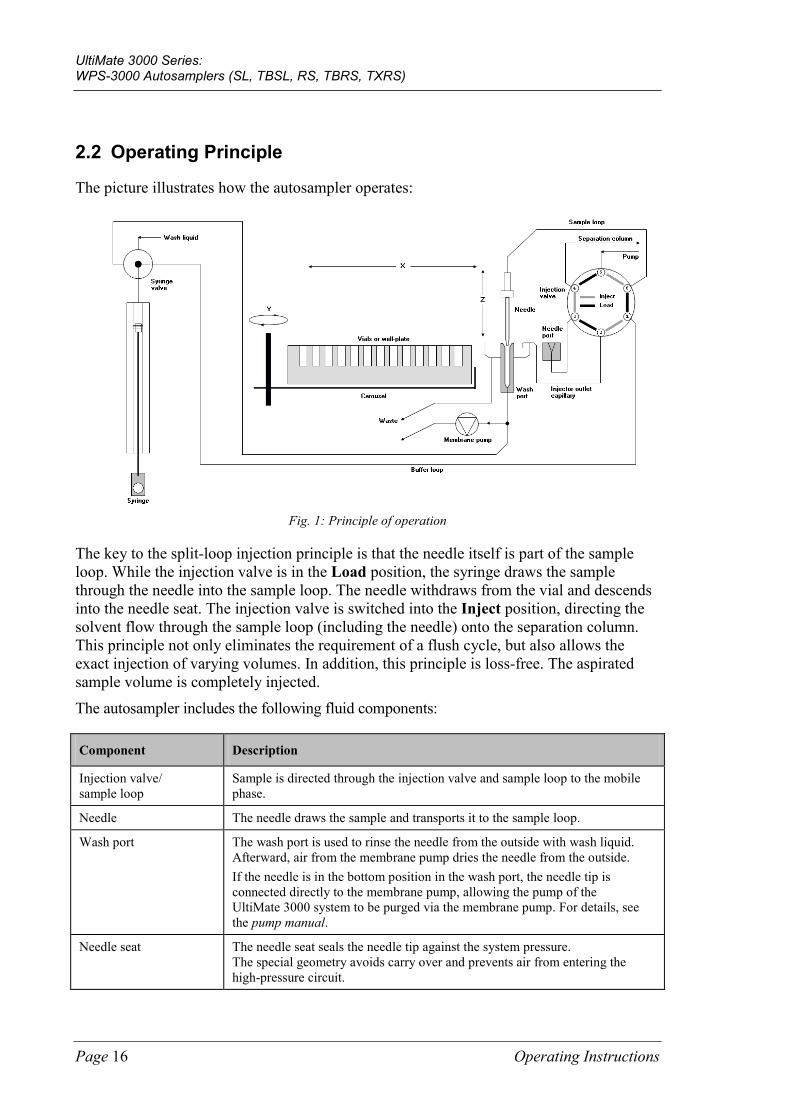
Fig. 1: Principle of operation
The key to the split-loop injection principle is that the needle itself is part of the sample loop. While the injection valve is in the Load position, the syringe draws the sample through the needle into the sample loop. The needle withdraws from the vial and descends into the needle seat. The injection valve is switched into the Inject position, directing the solvent flow through the sample loop (including the needle) onto the separation column. This principle not only eliminates the requirement of a flush cycle, but also allows the exact injection of varying volumes. In addition, this principle is loss-free. The aspirated sample volume is completely injected.
The autosampler includes the following fluid components:
Component Description
Injection valve/ sample loop
Sample is directed through the injection valve and sample loop to the mobile phase.
Needle The needle draws the sample and transports it to the sample loop.
Wash port The wash port is used to rinse the needle from the outside with wash liquid. Afterward, air from the membrane pump dries the needle from the outside. If the needle is in the bottom position in the wash port, the needle tip is connected directly to the membrane pump, allowing the pump of the UltiMate 3000 system to be purged via the membrane pump. For details, see the pump manual.
Needle seat The needle seat seals the needle tip against the system pressure. The special geometry avoids carry over and prevents air from entering the high-pressure circuit.
UltiMate 3000 Series: WPS-3000 Autosamplers (SL, TBSL, RS, TBRS, TXRS)
Operating Instructions Page 17
Component Description
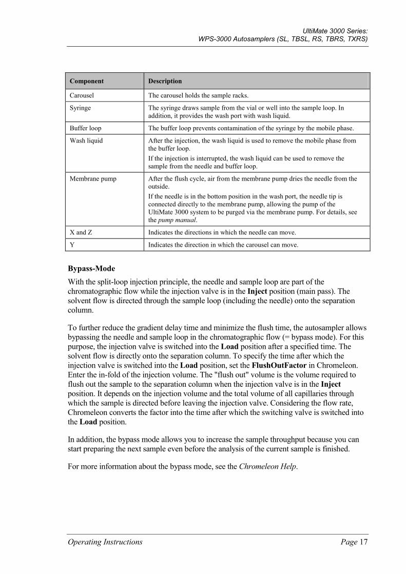
Carousel The carousel holds the sample racks.
Syringe The syringe draws sample from the vial or well into the sample loop. In addition, it provides the wash port with wash liquid.
Buffer loop The buffer loop prevents contamination of the syringe by the mobile phase.
Wash liquid After the injection, the wash liquid is used to remove the mobile phase from the buffer loop. If the injection is interrupted, the wash liquid can be used to remove the sample from the needle and buffer loop.
Membrane pump After the flush cycle, air from the membrane pump dries the needle from the outside. If the needle is in the bottom position in the wash port, the needle tip is connected directly to the membrane pump, allowing the pump of the UltiMate 3000 system to be purged via the membrane pump. For details, see the pump manual.
X and Z Indicates the directions in which the needle can move.
Y Indicates the direction in which the carousel can move.
Bypass-Mode With the split-loop injection principle, the needle and sample loop are part of the chromatographic flow while the injection valve is in the Inject position (main pass). The solvent flow is directed through the sample loop (including the needle) onto the separation column.
To further reduce the gradient delay time and minimize the flush time, the autosampler allows bypassing the needle and sample loop in the chromatographic flow (= bypass mode). For this purpose, the injection valve is switched into the Load position after a specified time. The solvent flow is directly onto the separation column. To specify the time after which the injection valve is switched into the Load position, set the FlushOutFactor in Chromeleon. Enter the in-fold of the injection volume. The "flush out" volume is the volume required to flush out the sample to the separation column when the injection valve is in the Inject position. It depends on the injection volume and the total volume of all capillaries through which the sample is directed before leaving the injection valve. Considering the flow rate, Chromeleon converts the factor into the time after which the switching valve is switched into the Load position.
In addition, the bypass mode allows you to increase the sample throughput because you can start preparing the next sample even before the analysis of the current sample is finished.
For more information about the bypass mode, see the Chromeleon Help.
UltiMate 3000 Series: WPS-3000 Autosamplers (SL, TBSL, RS, TBRS, TXRS)
Page 18 Operating Instructions
2.3 Autosampler Configurations
2.3.1 Overview
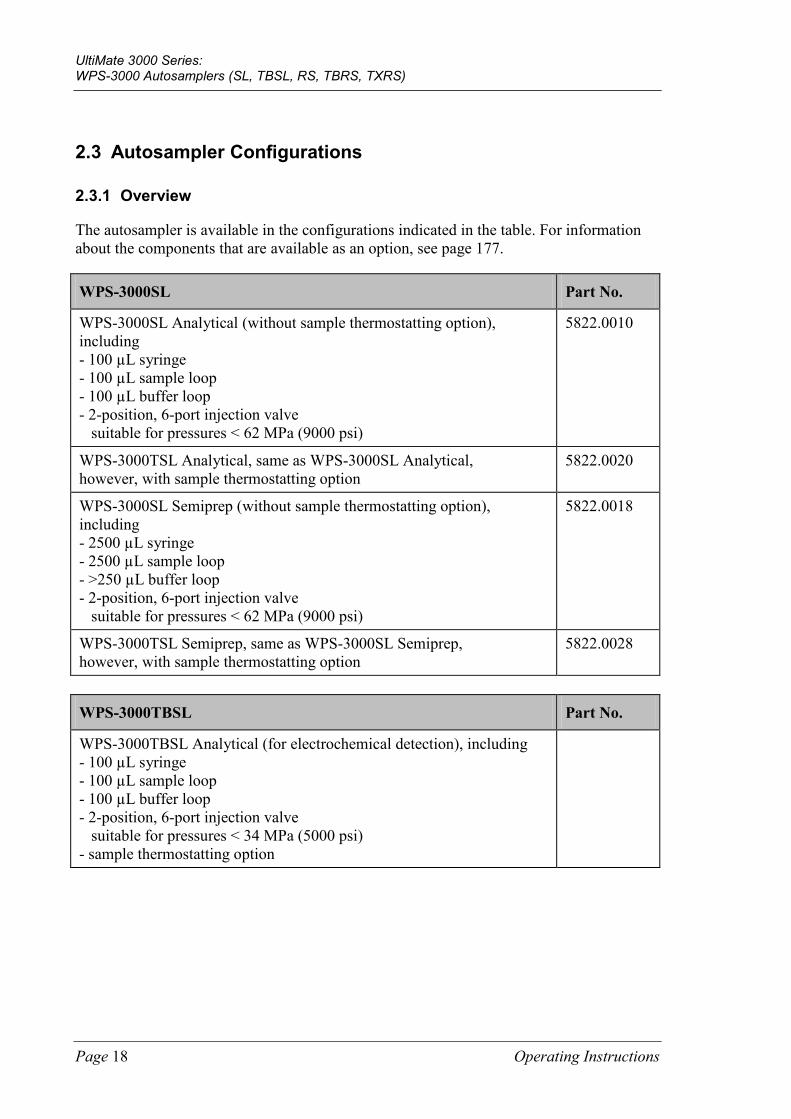
The autosampler is available in the configurations indicated in the table. For information about the components that are available as an option, see page 177.
WPS-3000SL Part No.
WPS-3000SL Analytical (without sample thermostatting option), including - 100 µL syringe - 100 µL sample loop - 100 µL buffer loop - 2-position, 6-port injection valve suitable for pressures < 62 MPa (9000 psi)
5822.0010
WPS-3000TSL Analytical, same as WPS-3000SL Analytical, however, with sample thermostatting option
5822.0020
WPS-3000SL Semiprep (without sample thermostatting option), including - 2500 µL syringe - 2500 µL sample loop - >250 µL buffer loop - 2-position, 6-port injection valve suitable for pressures < 62 MPa (9000 psi)
5822.0018
WPS-3000TSL Semiprep, same as WPS-3000SL Semiprep, however, with sample thermostatting option
5822.0028
WPS-3000TBSL Part No.
WPS-3000TBSL Analytical (for electrochemical detection), including - 100 µL syringe - 100 µL sample loop - 100 µL buffer loop - 2-position, 6-port injection valve suitable for pressures < 34 MPa (5000 psi) - sample thermostatting option
UltiMate 3000 Series: WPS-3000 Autosamplers (SL, TBSL, RS, TBRS, TXRS)
Operating Instructions Page 19
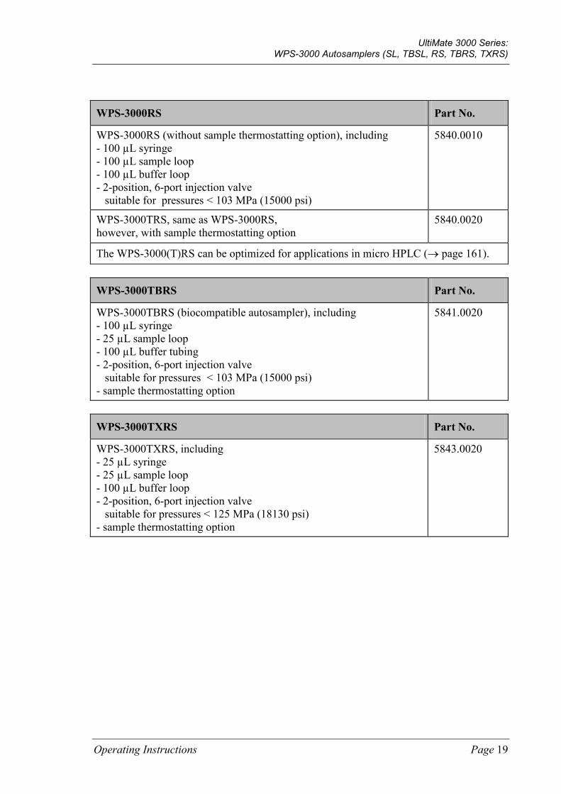
WPS-3000RS Part No.
WPS-3000RS (without sample thermostatting option), including - 100 µL syringe - 100 µL sample loop - 100 µL buffer loop - 2-position, 6-port injection valve suitable for pressures < 103 MPa (15000 psi)
5840.0010
WPS-3000TRS, same as WPS-3000RS, however, with sample thermostatting option
5840.0020
The WPS-3000(T)RS can be optimized for applications in micro HPLC (→ page 161).
WPS-3000TBRS Part No.
WPS-3000TBRS (biocompatible autosampler), including - 100 µL syringe - 25 µL sample loop - 100 µL buffer tubing - 2-position, 6-port injection valve suitable for pressures < 103 MPa (15000 psi) - sample thermostatting option
5841.0020
WPS-3000TXRS Part No.
WPS-3000TXRS, including - 25 µL syringe - 25 µL sample loop - 100 µL buffer loop - 2-position, 6-port injection valve suitable for pressures < 125 MPa (18130 psi) - sample thermostatting option
5843.0020
UltiMate 3000 Series: WPS-3000 Autosamplers (SL, TBSL, RS, TBRS, TXRS)
Page 20 Operating Instructions
2.3.2 Autosampler with Sample Thermostatting Option
Autosamplers with sample thermostatting option (indicated by the 'T' in the autosampler name) have electronic Peltier elements that cool or heat the carousel and all its components to the selected temperature, thus allowing precise equalization of the sample temperature.
The sample thermostatting option allows sample cooling by max. 22 °C from the ambient temperature. The lower temperature limit is +4 °C. In addition, the samples can be warmed to max. +45 °C.
Additional supplies such as cooling water or compressed air are not required.
Observe the following:
• To remove any condensation that may collect in the carousel, you can connect a waste line (drain tubing) to bottom right port (rear port) underneath the autosampler (→ Fig. 18, page 60). The thermostatted autosampler is equipped with active condensation drainage (via a pump).
• The drain tube must remain below the drain port. Otherwise, the liquid may flow back into the interior and cause damage to the autosampler.
• In case of increased condensation in the carousel, clean the carousel regularly to prevent impurities in the tray.
UltiMate 3000 Series: WPS-3000 Autosamplers (SL, TBSL, RS, TBRS, TXRS)
Operating Instructions Page 21
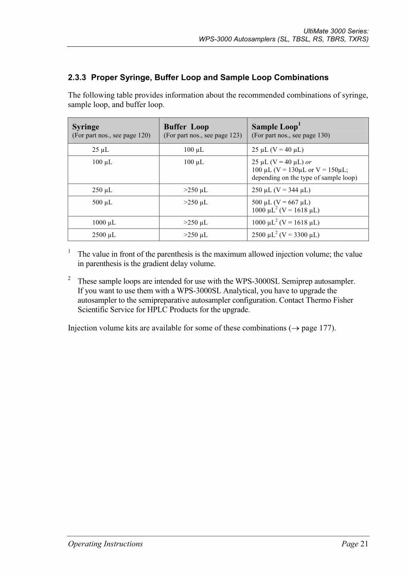
2.3.3 Proper Syringe, Buffer Loop and Sample Loop Combinations
The following table provides information about the recommended combinations of syringe, sample loop, and buffer loop.
Syringe (For part nos., see page 120)
Buffer Loop (For part nos., see page 123)
Sample Loop1 (For part nos., see page 130)
25 µL 100 µL 25 µL (V = 40 µL)
100 µL 100 µL 25 µL (V = 40 µL) or 100 µL (V = 130µL or V = 150µL; depending on the type of sample loop)
250 µL >250 µL 250 µL (V = 344 µL)
500 µL >250 µL 500 µL (V = 667 µL) 1000 µL2 (V = 1618 µL)
1000 µL >250 µL 1000 µL2 (V = 1618 µL)
2500 µL >250 µL 2500 µL2 (V = 3300 µL)
1 The value in front of the parenthesis is the maximum allowed injection volume; the value in parenthesis is the gradient delay volume.
2 These sample loops are intended for use with the WPS-3000SL Semiprep autosampler. If you want to use them with a WPS-3000SL Analytical, you have to upgrade the autosampler to the semipreparative autosampler configuration. Contact Thermo Fisher Scientific Service for HPLC Products for the upgrade.
Injection volume kits are available for some of these combinations (→ page 177).

UltiMate 3000 Series: WPS-3000 Autosamplers (SL, TBSL, RS, TBRS, TXRS)
Page 22 Operating Instructions
2.4 Interior Components
Fig. 2: Interior view
No. Description
1 Front panel (tilted upward) 2 Syringe valve (→ page 59) 3 Compartment lights (here hidden by the front panel; → page 30) 4 Tubing from syringe valve to wash port (wash port supply) 5 Syringe 6 Position for optional wash liquid bottle (for 125 mL of wash liquid; → page 56) 7 Menu pen 8 Movable cover for the carousel
To access to the samples in the carousel, grasp and move the cover at the black bar to the left. To close the carousel, move the cover to the right until it contacts the needle arm. The needle arm opens and closes the cover automatically for sampling.
9 Buffer loop 10 Leak sensor 11 Drip tray (→ detailed view in Fig. 3, page 23) 12 Injection valve (→ page 32) 13 Sample loop
1
2
5
6
7
4
8
9
11
12
10
3
13
UltiMate 3000 Series: WPS-3000 Autosamplers (SL, TBSL, RS, TBRS, TXRS)
Operating Instructions Page 23
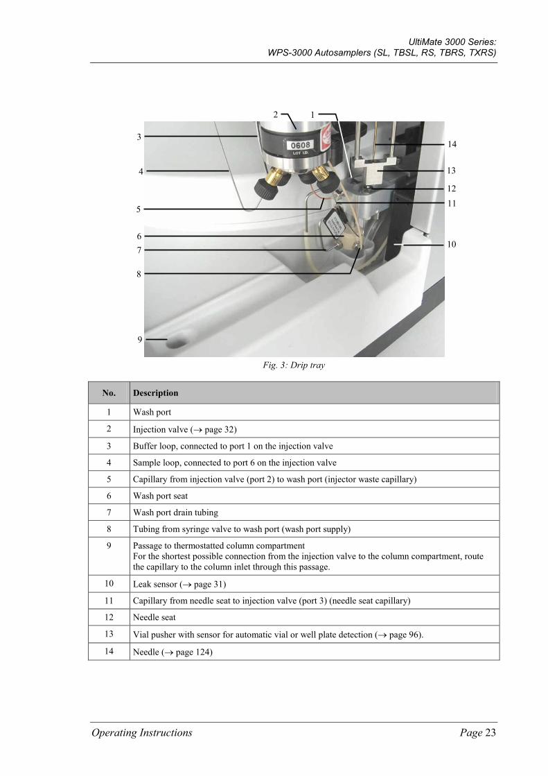
Fig. 3: Drip tray
No. Description
1 Wash port
2 Injection valve (→ page 32)
3 Buffer loop, connected to port 1 on the injection valve
4 Sample loop, connected to port 6 on the injection valve
5 Capillary from injection valve (port 2) to wash port (injector waste capillary)
6 Wash port seat
7 Wash port drain tubing
8 Tubing from syringe valve to wash port (wash port supply)
9 Passage to thermostatted column compartment For the shortest possible connection from the injection valve to the column compartment, route the capillary to the column inlet through this passage.
10 Leak sensor (→ page 31)
11 Capillary from needle seat to injection valve (port 3) (needle seat capillary)
12 Needle seat
13 Vial pusher with sensor for automatic vial or well plate detection (→ page 96).
14 Needle (→ page 124)
2
4
7
8
11
9
5
14
13
12
3
6
1
10
UltiMate 3000 Series: WPS-3000 Autosamplers (SL, TBSL, RS, TBRS, TXRS)
Page 24 Operating Instructions
2.5 Front Panel Elements
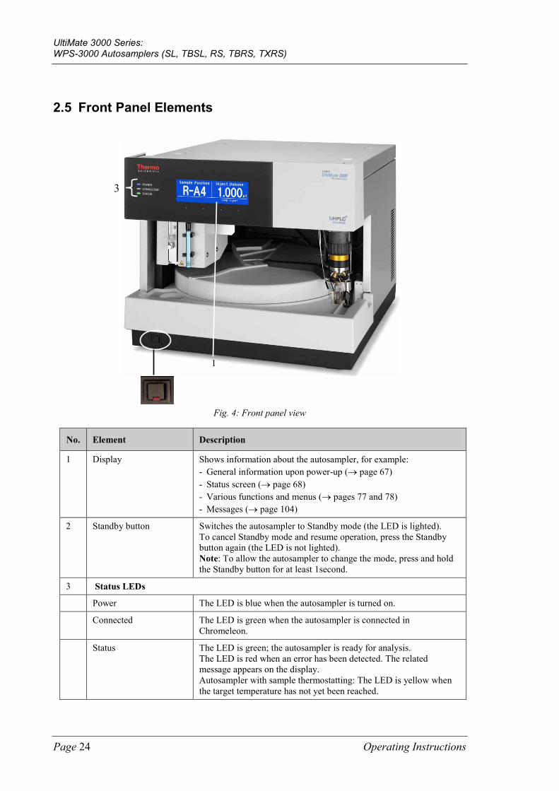
Fig. 4: Front panel view
No. Element Description
1 Display Shows information about the autosampler, for example: - General information upon power-up (→ page 67) - Status screen (→ page 68) - Various functions and menus (→ pages 77 and 78) - Messages (→ page 104)
2 Standby button Switches the autosampler to Standby mode (the LED is lighted). To cancel Standby mode and resume operation, press the Standby button again (the LED is not lighted). Note: To allow the autosampler to change the mode, press and hold the Standby button for at least 1second.
3 Status LEDs
Power The LED is blue when the autosampler is turned on.
Connected The LED is green when the autosampler is connected in Chromeleon.
Status The LED is green; the autosampler is ready for analysis. The LED is red when an error has been detected. The related message appears on the display. Autosampler with sample thermostatting: The LED is yellow when the target temperature has not yet been reached.
3
1
UltiMate 3000 Series: WPS-3000 Autosamplers (SL, TBSL, RS, TBRS, TXRS)
Operating Instructions Page 25
2.6 Rear Panel
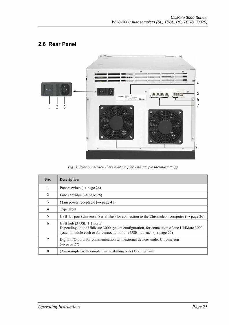
Fig. 5: Rear panel view (here autosampler with sample thermostatting)
No. Description
1 Power switch (→ page 26)
2 Fuse cartridge (→ page 26)
3 Main power receptacle (→ page 41)
4 Type label
5 USB 1.1 port (Universal Serial Bus) for connection to the Chromeleon computer (→ page 26)
6 USB hub (3 USB 1.1 ports) Depending on the UltiMate 3000 system configuration, for connection of one UltiMate 3000 system module each or for connection of one USB hub each (→ page 26)
7 Digital I/O ports for communication with external devices under Chromeleon (→ page 27)
8 (Autosampler with sample thermostatting only) Cooling fans
3 2 1
7 6 5
8
4
UltiMate 3000 Series: WPS-3000 Autosamplers (SL, TBSL, RS, TBRS, TXRS)
Page 26 Operating Instructions
2.6.1 Power Switch
The main power switch is on the rear panel. The main power switch is used to turn the autosampler on or off.
2.6.2 Fuse Cartridge
The fuse cartridge contains two slow-blow fuses, depending on the autosampler model rated at 2 A, 250 V (autosampler without sample thermostatting) or 4 A, 250 V (auto-sampler with sample thermostatting). For information about how to change the fuses, see page 157.
2.6.3 USB Port (USB 1.1)
The Chromeleon Chromatography Management System can use a USB connection to control the autosampler. Data is transferred digitally via the appropriate USB cable (→ page 40).
Depending on the configuration of the UltiMate 3000 system, you can use the internal 3-port USB hub (→ Fig. 5, no. 6) to connect other modules in the UltiMate 3000 system or external USB hubs. USB 2.0 devices cannot be connected.
Important: Thermo Fisher Scientific recommends using these USB ports for connections to Dionex instruments only. Thermo Fisher Scientific cannot guarantee correct functioning if instruments from other manufacturers are connected.
Important: Thermo Fisher Scientific recommande d'utiliser les ports USB uniquement pour les raccordements aux instruments Dionex. Thermo Fisher Scientific ne peut garantir le bon fonctionnement si les instruments d'autres fabricants sont raccordés.
For information about how to connect the autosampler to the Chromeleon computer, see sections 3.4.1 and 3.4.2 (→ page 40).
UltiMate 3000 Series: WPS-3000 Autosamplers (SL, TBSL, RS, TBRS, TXRS)
Operating Instructions Page 27
2.6.4 Digital I/O Ports
The 6-pin Mini-DIN ports on the rear panel can be used in Chromeleon to exchange digital signals with external devices. The signals are transferred via the appropriate signal cable (part no. 6000.1004). For information about the cable and about how to connect the digital I/O, see page 41. For information about the functions of the connector pins and pin assignment, see page 191.
If the UltiMate 3000 system includes a LPG-3400XRS pump, the pump has to be connected to a Digital I/O port on the autosampler if you want to synchronize the injection command with the pump strokes. For details, refer to the Operating Instructions for the pump.
UltiMate 3000 Series: WPS-3000 Autosamplers (SL, TBSL, RS, TBRS, TXRS)
Page 28 Operating Instructions
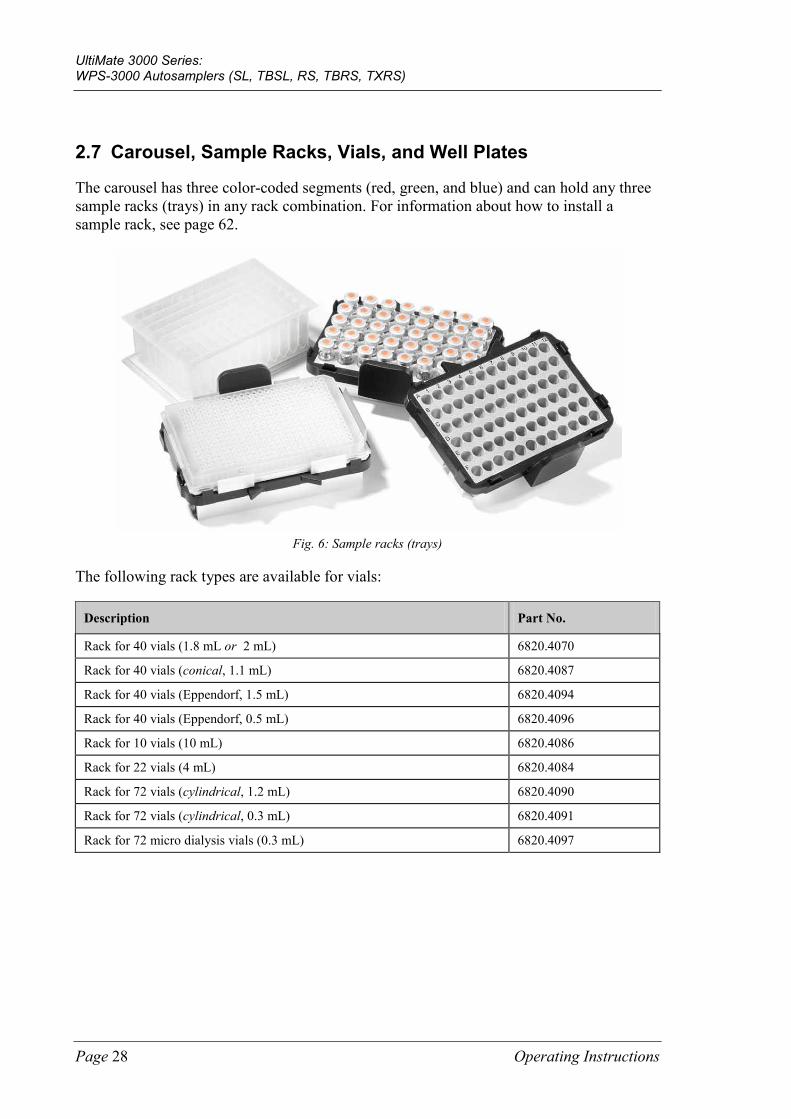
2.7 Carousel, Sample Racks, Vials, and Well Plates
The carousel has three color-coded segments (red, green, and blue) and can hold any three sample racks (trays) in any rack combination. For information about how to install a sample rack, see page 62.
Fig. 6: Sample racks (trays)
The following rack types are available for vials:
Description Part No.
Rack for 40 vials (1.8 mL or 2 mL) 6820.4070
Rack for 40 vials (conical, 1.1 mL) 6820.4087
Rack for 40 vials (Eppendorf, 1.5 mL) 6820.4094
Rack for 40 vials (Eppendorf, 0.5 mL) 6820.4096
Rack for 10 vials (10 mL) 6820.4086
Rack for 22 vials (4 mL) 6820.4084
Rack for 72 vials (cylindrical, 1.2 mL) 6820.4090
Rack for 72 vials (cylindrical, 0.3 mL) 6820.4091
Rack for 72 micro dialysis vials (0.3 mL) 6820.4097
UltiMate 3000 Series: WPS-3000 Autosamplers (SL, TBSL, RS, TBRS, TXRS)
Operating Instructions Page 29
The following rack types are available for well plates:
Description Part No.
Sample rack for normal well plate (plate height: 12 - 24 mm) 6820.4070, 6820.4084, 6820.4086, 6820.4087, 6820.4090, or 6820.4091
Sample rack for deep well plate (plate height: 34 - 46 mm) 6820.4079
Sample rack for deep well plate (plate height: 30 - 36 mm) 6820.4083
Sample rack for deep well plate (plate height: 20 – 32 mm) 6820.4089
Sample rack for low well PCR plate (plate height: 8 - 12 mm) 6820.4070, 6820.4086, 6820.4087, 6820.4090, or 6820.4091 In addition, an adapter is required (part. no. 6820.4088).
In addition, each color-coded segment can accommodate one 5-position vial holder that can hold 10 mL vials, such as reagent vials (→ page 64).
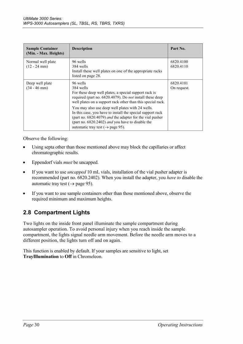
The table lists the vials and (deep) well plates that are recommended by Thermo Fisher Scientific along with the required minimum and maximum container heights:
Sample Container (Min. - Max. Heights)
Description Part No.
Vials (31 - 43 mm)
Cylindrical vial up to 1.8 mL (O.D. < 12 mm) for example, 250 µL vials Caps and septa for 250 µL vials for 40-position rack (part no. 6820.4070)
6820.0029 6820.0028
1.2 mL vials (31 - 43 mm)
Cylindrical vial Crimp cap Septum (silicone/PTFE, slotted) for 72-position rack (part no. 6820.4090)
6000.0062 6000.0064 6000.0061
1.1 mL vials (31 - 43 mm)
Conical vial Crimp cap and slotted silicone/PTFE septum for 40-position rack (part no. 6820.4087)
6000.0077 6000.0076
1.8 mL vials (31 - 43 mm)
1.8 mL vial Crimp cap and septum for 40-position rack (part no. 6820.4070)
6000.0072 6000.0071
2 mL vials (31 - 43 mm)
2 mL vial Cap and Septum (silicone) for 40-position rack (part no. 6820.4070)
6000.0060 6000.0057 6000.0058
4 mL vials (36 - 48 mm)
4 mL vial Screw cap Septum (silicone/PTFE) for 22-position rack (part no. 6820.4084)
6000.0074 6000.0073 6000.0075
10 mL vials (38 - 50 mm)
Cylindrical vial with cap and septum for 5-position holder (part no. 6820.4073)
6820.0023
UltiMate 3000 Series: WPS-3000 Autosamplers (SL, TBSL, RS, TBRS, TXRS)
Page 30 Operating Instructions
Sample Container (Min. - Max. Heights)
Description Part No.
Normal well plate (12 - 24 mm)
96 wells 384 wells Install these well plates on one of the appropriate racks listed on page 28.
6820.4100 6820.4110
Deep well plate (34 - 46 mm)
96 wells 384 wells For these deep well plates, a special support rack is required (part no. 6820.4079). Do not install these deep well plates on a support rack other than this special rack. You may also use deep well plates with 24 wells. In this case, you have to install the special support rack (part no. 6820.4079) and the adapter for the vial pusher (part no. 6820.2402) and you have to disable the automatic tray test (→ page 95).
6820.4101 On request.
Observe the following:
• Using septa other than those mentioned above may block the capillaries or affect chromatographic results.
• Eppendorf vials must be uncapped.
• If you want to use uncapped 10 mL vials, installation of the vial pusher adapter is recommended (part no. 6820.2402). When you install the adapter, you have to disable the automatic tray test (→ page 95).
• If you want to use sample containers other than those mentioned above, observe the required minimum and maximum heights.
2.8 Compartment Lights
Two lights on the inside front panel illuminate the sample compartment during autosampler operation. To avoid personal injury when you reach inside the sample compartment, the lights signal needle arm movement. Before the needle arm moves to a different position, the lights turn off and on again.
This function is enabled by default. If your samples are sensitive to light, set TrayIllumination to Off in Chromeleon.
UltiMate 3000 Series: WPS-3000 Autosamplers (SL, TBSL, RS, TBRS, TXRS)
Operating Instructions Page 31
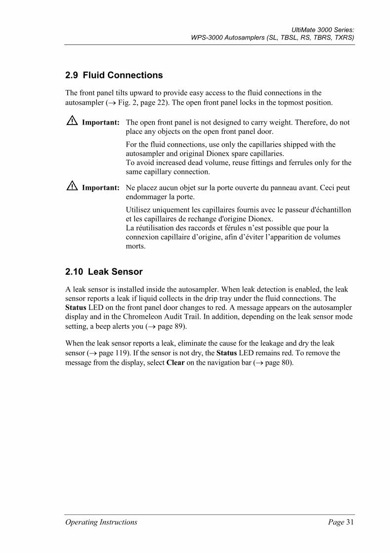
2.9 Fluid Connections
The front panel tilts upward to provide easy access to the fluid connections in the autosampler (→ Fig. 2, page 22). The open front panel locks in the topmost position.
Important: The open front panel is not designed to carry weight. Therefore, do not place any objects on the open front panel door.
For the fluid connections, use only the capillaries shipped with the autosampler and original Dionex spare capillaries. To avoid increased dead volume, reuse fittings and ferrules only for the same capillary connection.
Important: Ne placez aucun objet sur la porte ouverte du panneau avant. Ceci peut endommager la porte.
Utilisez uniquement les capillaires fournis avec le passeur d'échantillon et les capillaires de rechange d'origine Dionex. La réutilisation des raccords et férules n’est possible que pour la connexion capillaire d’origine, afin d’éviter l’apparition de volumes morts.
2.10 Leak Sensor
A leak sensor is installed inside the autosampler. When leak detection is enabled, the leak sensor reports a leak if liquid collects in the drip tray under the fluid connections. The Status LED on the front panel door changes to red. A message appears on the autosampler display and in the Chromeleon Audit Trail. In addition, depending on the leak sensor mode setting, a beep alerts you (→ page 89).
When the leak sensor reports a leak, eliminate the cause for the leakage and dry the leak sensor (→ page 119). If the sensor is not dry, the Status LED remains red. To remove the message from the display, select Clear on the navigation bar (→ page 80).
UltiMate 3000 Series: WPS-3000 Autosamplers (SL, TBSL, RS, TBRS, TXRS)
Page 32 Operating Instructions
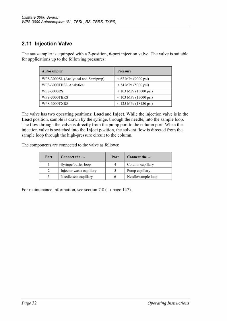
2.11 Injection Valve
The autosampler is equipped with a 2-position, 6-port injection valve. The valve is suitable for applications up to the following pressures:
Autosampler Pressure
WPS-3000SL (Analytical and Semiprep) < 62 MPa (9000 psi) WPS-3000TBSL Analytical < 34 MPa (5000 psi) WPS-3000RS < 103 MPa (15000 psi) WPS-3000TBRS < 103 MPa (15000 psi) WPS-3000TXRS < 125 MPa (18130 psi)
The valve has two operating positions: Load and Inject. While the injection valve is in the Load position, sample is drawn by the syringe, through the needle, into the sample loop. The flow through the valve is directly from the pump port to the column port. When the injection valve is switched into the Inject position, the solvent flow is directed from the sample loop through the high-pressure circuit to the column.
The components are connected to the valve as follows:
Port Connect the … Port Connect the …
1 Syringe/buffer loop 4 Column capillary 2 Injector waste capillary 5 Pump capillary 3 Needle seat capillary 6 Needle/sample loop
For maintenance information, see section 7.8 (→ page 147).
UltiMate 3000 Series: WPS-3000 Autosamplers (SL, TBSL, RS, TBRS, TXRS)
Operating Instructions Page 33
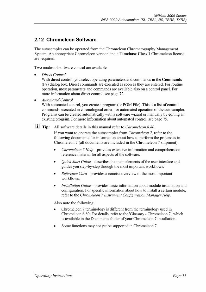
2.12 Chromeleon Software
The autosampler can be operated from the Chromeleon Chromatography Management System. An appropriate Chromeleon version and a Timebase Class 1 Chromeleon license are required.
Two modes of software control are available:
• Direct Control With direct control, you select operating parameters and commands in the Commands (F8) dialog box. Direct commands are executed as soon as they are entered. For routine operation, most parameters and commands are available also on a control panel. For more information about direct control, see page 72.
• Automated Control With automated control, you create a program (or PGM File). This is a list of control commands, executed in chronological order, for automated operation of the autosampler. Programs can be created automatically with a software wizard or manually by editing an existing program. For more information about automated control, see page 75.
Tip: All software details in this manual refer to Chromeleon 6.80. If you want to operate the autosampler from Chromeleon 7, refer to the following documents for information about how to perform the processes in Chromeleon 7 (all documents are included in the Chromeleon 7 shipment):
• Chromeleon 7 Help—provides extensive information and comprehensive reference material for all aspects of the software.
• Quick Start Guide—describes the main elements of the user interface and guides you step-by-step through the most important workflows.
• Reference Card—provides a concise overview of the most important workflows.
• Installation Guide—provides basic information about module installation and configuration. For specific information about how to install a certain module, refer to the Chromeleon 7 Instrument Configuration Manager Help.
Also note the following: • Chromeleon 7 terminology is different from the terminology used in
Chromeleon 6.80. For details, refer to the 'Glossary - Chromeleon 7,' which is available in the Documents folder of your Chromeleon 7 installation.
• Some functions may not yet be supported in Chromeleon 7.
UltiMate 3000 Series: WPS-3000 Autosamplers (SL, TBSL, RS, TBRS, TXRS)
Page 34 Operating Instructions
2.13 System Wellness, Predictive Performance, and Diagnostics
System Wellness monitors the health of the autosampler. The autosampler supports several performance and reliability features that can help you detect small problems before they turn into big ones:
• Internal monitoring of all mechanical operations
• Automatic self test upon power-up
• Automatic plate and vial detection (→ page 96)
• Leak sensor (→ page 31)
• Monitoring of the cooling performance by three temperature sensors
When an error is detected, the Status LED on the front panel changes to red and a message appears on the autosampler display (→ page 104).
When the autosampler is operated from Chromeleon, additional functions for estimating the lifetime of consumables and monitoring and recording service and (re)qualification information (= predictive performance) are available (→ page 91). To check the performance of certain autosampler components and the overall performance of the instrument, Chromeleon also supports diagnostic functions for the autosampler (→ page 92).
UltiMate 3000 Series: WPS-3000 Autosamplers (SL, TBSL, RS, TBRS, TXRS)
Operating Instructions Page 35
3 Installation
3.1 Facility Requirements
The installation site must meet the following requirements:
• The main power switch and the main power receptacle are on the rear panel. Make sure that
♦ Free and unrestricted access to the main power switch is ensured at all times.
♦ The power cord of the device can be easily reached and disconnected from the power line at all times. Provide sufficient space behind the device to unplug the cable.
• Make sure that the installation site meets the power and environmental specifications listed in the Technical Information section (→ page 163).
• Install the autosampler in the laboratory on a stable surface that is free of vibrations.
• Make sure that the surface is resistant to solvents.
• Avoid locations with extreme changes in temperature (such as direct sunlight or drafts) and high humidity.
• Allow sufficient clearance behind and on the sides the autosampler for ventilation.
UltiMate 3000 Series: WPS-3000 Autosamplers (SL, TBSL, RS, TBRS, TXRS)
Page 36 Operating Instructions
3.2 Unpacking
All electrical and mechanical components of the autosampler are carefully tested before the instrument is shipped from the factory. After unpacking, inspect the instrument for any signs of mechanical damage, which might have occurred during transit.
Tips: Immediately report any shipping damage to both, the incoming carrier and Thermo Fisher Scientific. Shipping insurance will compensate for the damage only if reported immediately.
Keep the original shipping container and packing material. They provide excellent protection for the autosampler in case of future transit. The product warranty will not be honored if the autosampler is shipped in any other packaging.
1. Place the shipping container on the floor and remove the accessories kit and the power cord. All moving parts of the rotary unit (sample racks, well plates) are shipped in a separate box.
2. Grasp the autosampler by the sides. Slowly and carefully, pull the instrument out of the shipping container and place it on a stable surface.
Important: A team effort is required to lift or move the autosampler. The autosampler is too heavy and/or bulky for one person alone to lift or move safely.
To prevent the unit from falling, lift the unit by the sides. Do not lift the autosampler by the packing material. When lifting or moving the autosampler, always lift by the bottom or sides of the unit.
Important: Vous ne devriez pas soulever le passeur d'échantillon seul. Le passeur d'échantillon est trop lourd et trop encombrant pour une seule personne. Lorsque vous soulevez ou déplacez le passeur d'échantillon, soulevez toujours par le bas ou les côtés, avec le panneau avant fermé afin de ne pas endommager l'instrument. Lorsque vous soulevez ou déplacez le passeur d'échantillon, soulevez toujours par le bas ou les côtés.
3. Remove the foam spacers, and then remove the polythene packaging.
4. Remove the foam inserts that protect the autosampler during shipment.
♦ Remove the foam insert that secures the needle arm and carousel.
♦ Tilt the front panel upward and remove the two foam inserts securing the front panel.
UltiMate 3000 Series: WPS-3000 Autosamplers (SL, TBSL, RS, TBRS, TXRS)
Operating Instructions Page 37
5. Before connecting the autosampler to the power source, wait approximately four hours to allow the instrument to come to room temperature and to allow any condensation that might have occurred during shipping to evaporate. After four hours, check the autosampler; if condensation still exists, allow the autosampler to continue to warm up (without connecting it to the power source) until the condensation is completely gone.
UltiMate 3000 Series: WPS-3000 Autosamplers (SL, TBSL, RS, TBRS, TXRS)
Page 38 Operating Instructions
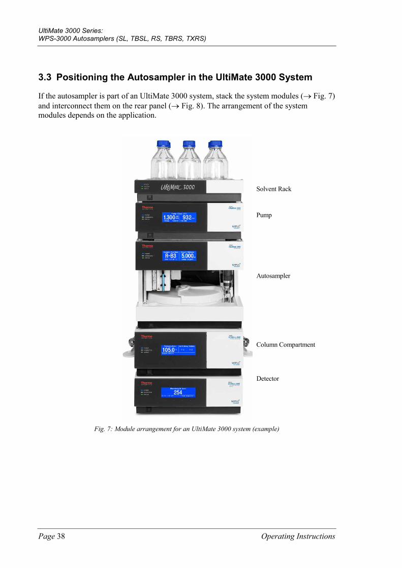
3.3 Positioning the Autosampler in the UltiMate 3000 System
If the autosampler is part of an UltiMate 3000 system, stack the system modules (→ Fig. 7) and interconnect them on the rear panel (→ Fig. 8). The arrangement of the system modules depends on the application.
Fig. 7: Module arrangement for an UltiMate 3000 system (example)
Detector
Autosampler
Column Compartment
Pump
Solvent Rack
UltiMate 3000 Series: WPS-3000 Autosamplers (SL, TBSL, RS, TBRS, TXRS)
Operating Instructions Page 39
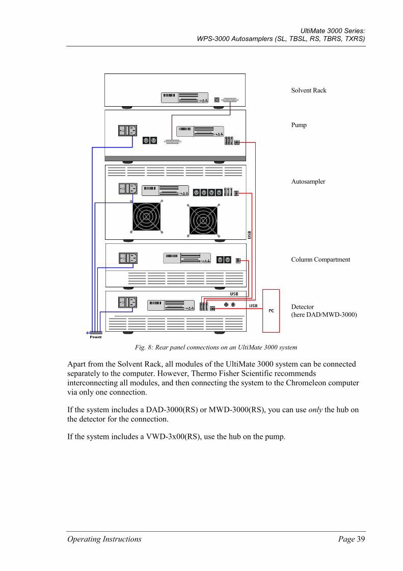
Fig. 8: Rear panel connections on an UltiMate 3000 system
Apart from the Solvent Rack, all modules of the UltiMate 3000 system can be connected separately to the computer. However, Thermo Fisher Scientific recommends interconnecting all modules, and then connecting the system to the Chromeleon computer via only one connection.
If the system includes a DAD-3000(RS) or MWD-3000(RS), you can use only the hub on the detector for the connection.
If the system includes a VWD-3x00(RS), use the hub on the pump.
Autosampler
Column Compartment
Pump
Solvent Rack
Detector (here DAD/MWD-3000)
UltiMate 3000 Series: WPS-3000 Autosamplers (SL, TBSL, RS, TBRS, TXRS)
Page 40 Operating Instructions
3.4 Connecting the Autosampler
3.4.1 General Information
If you want to operate the autosampler from Chromeleon Before you connect the autosampler to the USB port on the Chromeleon computer and turn on the autosampler power, verify that Chromeleon is installed on the computer and that the license code is entered. Only if you install Chromeleon first, the USB driver for the autosampler is automatically loaded and the Windows® operating system can detect the autosampler when the power is turned on.
3.4.2 Connecting the USB Cable
Connect the autosampler to the Chromeleon computer via the USB ports on the rear panel (→ Fig. 5, page 25). To do so, select one of the following alternatives:
• Connect the autosampler directly to the USB port on the Chromeleon computer.
• Connect the autosampler to the internal USB port on another module in the UltiMate 3000 system that is connected to the Chromeleon computer (→ page 39).
• Connect the autosampler to the Chromeleon computer via an external USB hub.
To ensure trouble-free operation, use only these cables for the connection:
Cable Part No.
USB cable, type A to type B High Speed USB 2.0 (cable length: 1m)
6035.9035 (shipped with the autosampler)
USB cable, type A to type B High Speed USB 2.0 (cable length: 5m)
6911.0002
Tip: The USB standard limits the USB cable length to 5 meters. Each USB device can be separated from the computer or next USB hub by no more than 5 meters.

UltiMate 3000 Series: WPS-3000 Autosamplers (SL, TBSL, RS, TBRS, TXRS)
Operating Instructions Page 41
3.4.3 Connecting the Power Cord
Use the power cord shipped with the autosampler to connect the instrument to the main power source. Connect the power cord from the main power receptacle on the rear panel (→ Fig. 5, page 25) to the power source that is connected to a true ground. You need not adapt the line voltage to local voltage requirements.
Warning: Never use a power cord other than the power cords provided for the device.
Do not use multiple sockets or extension cords. Using defective multiple sockets or extension cords may cause personal injury or damage to the device.
Avertissement: Utilisez uniquement les cordons d’alimentation électrique spécifique à l’instrument.
N'utilisez pas des blocs multiprise ou des câbles prolongateurs. Cela pourrait entraîner des blessures corporelles ou endommager l'instrument.
3.4.4 Connecting the Digital I/O
To connect an external device to the digital I/O ports on the rear panel, use the 6-pin Mini-DIN signal cable (part no. 6000.1004).
1. Plug the 6-pin connector of the mini-DIN cable into the Digital I/O port 1 (2, 3, or 4). For information about the functions of the connector pins and pin assignment, see page 191.
2. For each relay output or digital input to be used, connect the appropriate signal wires and ground wire to the corresponding connectors on the external device (→ documentation provided with the external device).
Tip: To connect a LPG-3400XRS pump, follow the procedure described in the Operating Instructions for the pump.
3. When configuring the autosampler in the Chromeleon Server Configuration program, make the following settings:
• On the Relays page, select the corresponding relay output (→ page 49).
• On the Inputs page, select the corresponding digital input (→ page 49).
UltiMate 3000 Series: WPS-3000 Autosamplers (SL, TBSL, RS, TBRS, TXRS)
Page 42 Operating Instructions
3.5 Setting Up the Autosampler in Chromeleon
This section provides brief instructions for setting up the autosampler in Chromeleon. For details about any of these steps, see the Chromeleon Help. For information about how to set up the autosampler in DCMSLink, see section 3.6 (→ page 51).
Tip: When the autosampler is connected to the Chromeleon computer, verify that the Chromeleon software is installed before turning on the autosampler power for the first time. Only then, the Windows® operating system will detect the autosampler automatically when the autosampler power is turned on.
3.5.1 Loading the USB Driver for the Autosampler
1. Turn on the computer power, if it is not already on.
2. Under Windows Vista® (Windows® XP, Windows® 7, or Windows® Server 2008) log on as a • Local administrator if the computer is a local computer. • User with local computer administrator privileges if the computer is a network
computer.
3. Open the Chromeleon Server Monitor program by double-clicking the Chromeleon
Server Monitor icon on the Windows taskbar.
If the Server Monitor icon is not on the taskbar, click Start on the taskbar, point to Programs (or All Programs, depending on the operating system), point to Chromeleon, and then click Server Monitor.
4. Click Start to start the server.
5. Click Close to close the Server Monitor window. The Server Monitor icon appears on the taskbar.
Tip: Clicking the Quit Monitor button quits (exits) the Server Monitor program, but does not stop the server. To stop the server, click Stop.
6. Turn on the main power switch on the rear panel of the autosampler.
7. Windows Vista, Windows 7 and Windows Server 2008 will automatically detect the new autosampler and perform the USB installation.
If Windows fails to detect the autosampler and launches a wizard instead, this indicates that you connected the autosampler to the computer and turned on the power for the first time before you installed Chromeleon.

UltiMate 3000 Series: WPS-3000 Autosamplers (SL, TBSL, RS, TBRS, TXRS)
Operating Instructions Page 43
To resolve the problem:
a) Click Cancel to exit the wizard.
b) Turn off the autosampler.
c) Install Chromeleon.
d) Turn on the power to the autosampler. Windows will now detect the autosampler and install the USB software for the autosampler automatically.
Windows XP will automatically detect the new autosampler and launch the Found New Hardware Wizard, which guides you through the USB installation. Select the following options:
a) If asked whether Windows can connect to Windows Update to search for software, select No, not this time.
b) Accept the default option (Install the software automatically) and click Next>.
c) Click Finish when the wizard reports that the software for the autosampler has been installed.
If Windows fails to detect the autosampler and a message box asks for a USB configuration file (cmwdmusb.inf), this indicates that you connected the autosampler to the computer and turned on the power for the first time before you installed Chromeleon.
To resolve the problem:
a) Click Cancel in the Windows message box.
b) Turn off the autosampler.
c) Install Chromeleon.
d) Turn on the power to the autosampler. Windows will now automatically detect the autosampler and launch the Found New Hardware Wizard.
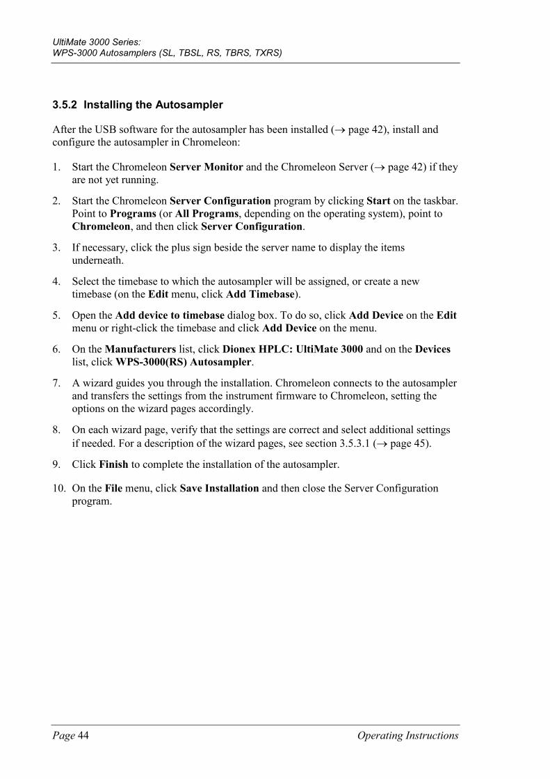
UltiMate 3000 Series: WPS-3000 Autosamplers (SL, TBSL, RS, TBRS, TXRS)
Page 44 Operating Instructions
3.5.2 Installing the Autosampler
After the USB software for the autosampler has been installed (→ page 42), install and configure the autosampler in Chromeleon:
1. Start the Chromeleon Server Monitor and the Chromeleon Server (→ page 42) if they are not yet running.
2. Start the Chromeleon Server Configuration program by clicking Start on the taskbar. Point to Programs (or All Programs, depending on the operating system), point to Chromeleon, and then click Server Configuration.
3. If necessary, click the plus sign beside the server name to display the items underneath.
4. Select the timebase to which the autosampler will be assigned, or create a new timebase (on the Edit menu, click Add Timebase).
5. Open the Add device to timebase dialog box. To do so, click Add Device on the Edit menu or right-click the timebase and click Add Device on the menu.
6. On the Manufacturers list, click Dionex HPLC: UltiMate 3000 and on the Devices list, click WPS-3000(RS) Autosampler.
7. A wizard guides you through the installation. Chromeleon connects to the autosampler and transfers the settings from the instrument firmware to Chromeleon, setting the options on the wizard pages accordingly.
8. On each wizard page, verify that the settings are correct and select additional settings if needed. For a description of the wizard pages, see section 3.5.3.1 (→ page 45).
9. Click Finish to complete the installation of the autosampler.
10. On the File menu, click Save Installation and then close the Server Configuration program.
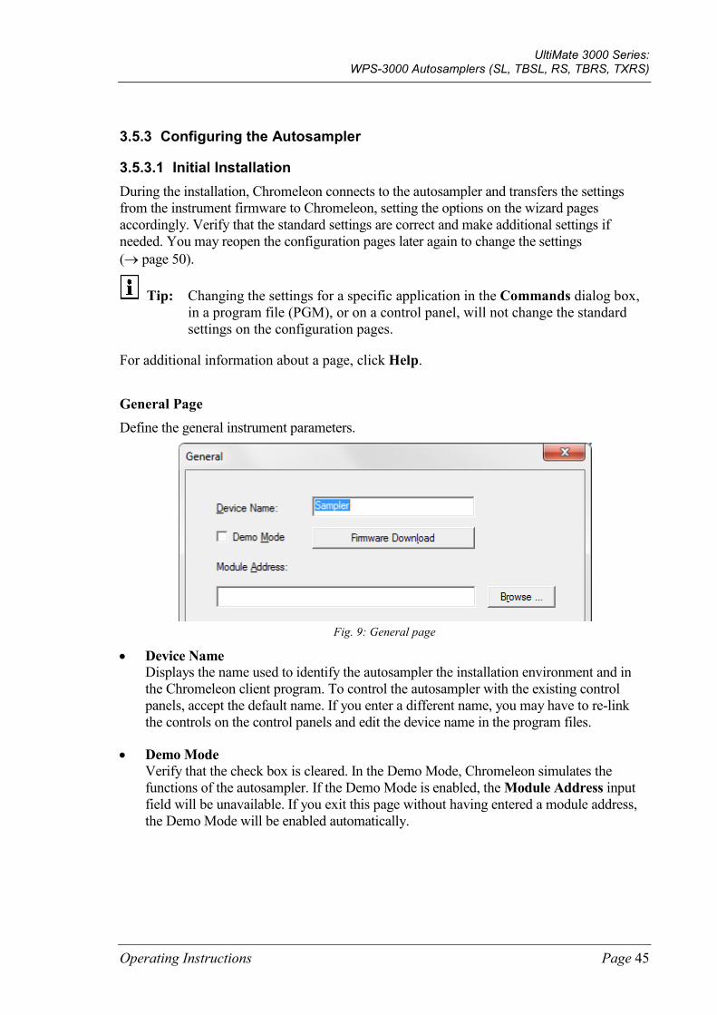
UltiMate 3000 Series: WPS-3000 Autosamplers (SL, TBSL, RS, TBRS, TXRS)
Operating Instructions Page 45
3.5.3 Configuring the Autosampler
3.5.3.1 Initial Installation During the installation, Chromeleon connects to the autosampler and transfers the settings from the instrument firmware to Chromeleon, setting the options on the wizard pages accordingly. Verify that the standard settings are correct and make additional settings if needed. You may reopen the configuration pages later again to change the settings (→ page 50).
Tip: Changing the settings for a specific application in the Commands dialog box, in a program file (PGM), or on a control panel, will not change the standard settings on the configuration pages.
For additional information about a page, click Help.
General Page Define the general instrument parameters.
Fig. 9: General page
• Device Name Displays the name used to identify the autosampler the installation environment and in the Chromeleon client program. To control the autosampler with the existing control panels, accept the default name. If you enter a different name, you may have to re-link the controls on the control panels and edit the device name in the program files.
• Demo Mode Verify that the check box is cleared. In the Demo Mode, Chromeleon simulates the functions of the autosampler. If the Demo Mode is enabled, the Module Address input field will be unavailable. If you exit this page without having entered a module address, the Demo Mode will be enabled automatically.
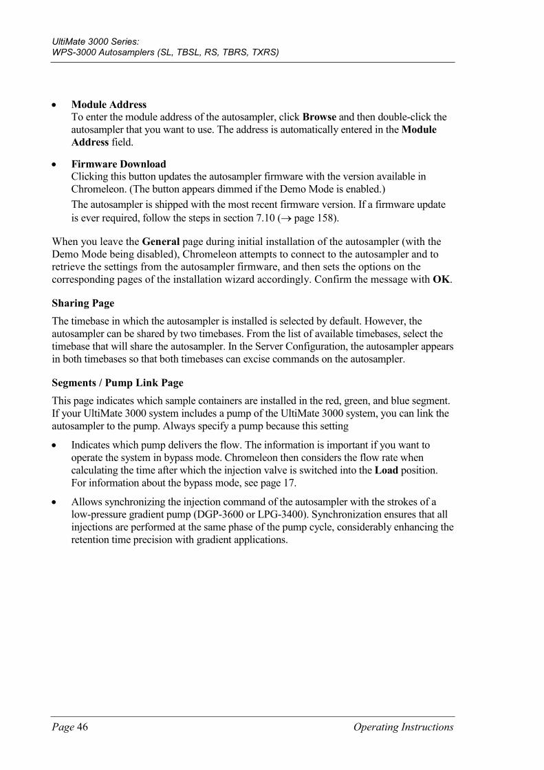
UltiMate 3000 Series: WPS-3000 Autosamplers (SL, TBSL, RS, TBRS, TXRS)
Page 46 Operating Instructions
• Module Address To enter the module address of the autosampler, click Browse and then double-click the autosampler that you want to use. The address is automatically entered in the Module Address field.
• Firmware Download Clicking this button updates the autosampler firmware with the version available in Chromeleon. (The button appears dimmed if the Demo Mode is enabled.) The autosampler is shipped with the most recent firmware version. If a firmware update is ever required, follow the steps in section 7.10 (→ page 158).
When you leave the General page during initial installation of the autosampler (with the Demo Mode being disabled), Chromeleon attempts to connect to the autosampler and to retrieve the settings from the autosampler firmware, and then sets the options on the corresponding pages of the installation wizard accordingly. Confirm the message with OK.
Sharing Page The timebase in which the autosampler is installed is selected by default. However, the autosampler can be shared by two timebases. From the list of available timebases, select the timebase that will share the autosampler. In the Server Configuration, the autosampler appears in both timebases so that both timebases can excise commands on the autosampler.
Segments / Pump Link Page This page indicates which sample containers are installed in the red, green, and blue segment. If your UltiMate 3000 system includes a pump of the UltiMate 3000 system, you can link the autosampler to the pump. Always specify a pump because this setting
• Indicates which pump delivers the flow. The information is important if you want to operate the system in bypass mode. Chromeleon then considers the flow rate when calculating the time after which the injection valve is switched into the Load position. For information about the bypass mode, see page 17.
• Allows synchronizing the injection command of the autosampler with the strokes of a low-pressure gradient pump (DGP-3600 or LPG-3400). Synchronization ensures that all injections are performed at the same phase of the pump cycle, considerably enhancing the retention time precision with gradient applications.
UltiMate 3000 Series: WPS-3000 Autosamplers (SL, TBSL, RS, TBRS, TXRS)
Operating Instructions Page 47
Fig. 10: Segments / Pump Link page
(here: when the UltiMate 3000 system includes a DGP-3600 pump)
• Well Plate Sampler Segment Types The section shows which sample containers are installed in the red, green, and blue segment (standard configuration). Verify that the settings match the installed sample containers. If you later install different sample containers, you have to adapt the settings in Chromeleon accordingly (→ page 87).
• Pump Link On the Flow through sampler is delivered by pump(s) list, select the pump to which the autosampler is linked. The list shows all pumps that are installed in the timebase.
Tip: If you want to link a LPG-3400XRS pump or if you want to link a LPG-3400XRS and a second pump to the autosampler, see the Operating Instructions for the LPG-3400XRS pump for a detailed description of the required settings.
♦ If the UltiMate 3000 system includes a DGP-3600 pump Select UM3PUMP_L_STRK to link the autosampler to the left pump. To link the autosampler to the right pump, select UM3PUMP_R_STRK.
♦ If the UltiMate 3000 system includes a pump other than a DGP-3600 Select UM3PUMP_STROKE.
♦ If you do not want to link the autosampler to a pump Select <None>.
Only if the autosampler is linked to a DGP-3600 or LPG-3400 pump on this page, synchronization of the injection command with the strokes of the pump will be possible.
In the Chromeleon Client program, you can then set whether you want to use synchronization and you can select a different pump if necessary (→ page 85).
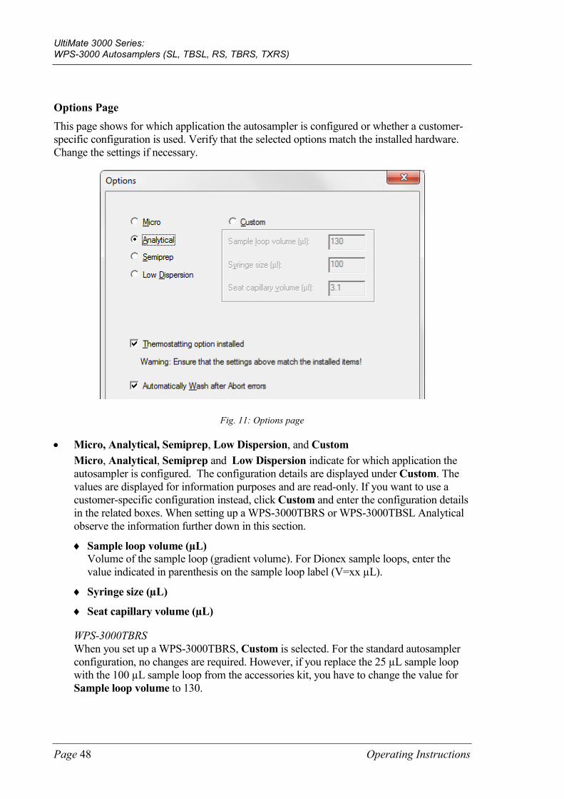
UltiMate 3000 Series: WPS-3000 Autosamplers (SL, TBSL, RS, TBRS, TXRS)
Page 48 Operating Instructions
Options Page This page shows for which application the autosampler is configured or whether a customer-specific configuration is used. Verify that the selected options match the installed hardware. Change the settings if necessary.
Fig. 11: Options page
• Micro, Analytical, Semiprep, Low Dispersion, and Custom Micro, Analytical, Semiprep and Low Dispersion indicate for which application the autosampler is configured. The configuration details are displayed under Custom. The values are displayed for information purposes and are read-only. If you want to use a customer-specific configuration instead, click Custom and enter the configuration details in the related boxes. When setting up a WPS-3000TBRS or WPS-3000TBSL Analytical observe the information further down in this section.
♦ Sample loop volume (µL) Volume of the sample loop (gradient volume). For Dionex sample loops, enter the value indicated in parenthesis on the sample loop label (V=xx µL).
♦ Syringe size (µL)
♦ Seat capillary volume (µL)
WPS-3000TBRS When you set up a WPS-3000TBRS, Custom is selected. For the standard autosampler configuration, no changes are required. However, if you replace the 25 µL sample loop with the 100 µL sample loop from the accessories kit, you have to change the value for Sample loop volume to 130.
UltiMate 3000 Series: WPS-3000 Autosamplers (SL, TBSL, RS, TBRS, TXRS)
Operating Instructions Page 49
WPS-3000TBSL Analytical If you want to set up a WPS-3000TBSL Analytical in Chromeleon, you have to adapt the value for Sample loop volume. Click Custom and type 150 in the Sample loop volume box.
• Thermostatting option installed When the autosampler supports sample thermostatting, verify that the check box is selected.
• Automatically Wash after Abort errors The check box is selected by default. Accept this setting to have Chromeleon automatically perform a wash cycle when an abort error occurred.
Each time the autosampler is connected in Chromeleon, the settings on the Segments / Pump Link and Options pages are compared to the instrument configuration reported by the autosampler upon connect. If the instrument configuration and the settings in Chromeleon do not match, the autosampler is disconnected in Chromeleon and a message appears in the Audit Trail. Check and match the settings if necessary by clicking either Retrieve configuration from module or Send configuration to module on the General page (→ page 50).
Relays Page The Relays page lists all available relays (Relay_1 to Relay_4). Select a check box to enable the corresponding relay. If a check box is cleared, the relay will not be available in Chromeleon. To change the relay name or timebase assignment, double-click the relay name (or press the F2 button) and make the changes in the Devices Configuration dialog box.
Inputs Page The Inputs page lists all available remote inputs (Input_1 to Input_4). Select a check box to enable the corresponding remote input. If a check box is cleared, the input will not be available in Chromeleon. To change the input name or timebase assignment, double-click the input name (or press the F2 button) and make the changes in the Devices Configuration dialog box.
UltiMate 3000 Series: WPS-3000 Autosamplers (SL, TBSL, RS, TBRS, TXRS)
Page 50 Operating Instructions
3.5.3.2 Changing the Configuration Properties To change the default configuration settings, reopen the configuration pages.
1. Start the Server Configuration program (→ page 44).
2. Right-click the autosampler in the timebase and click Properties on the menu.
3. Change the settings as needed. For a description of the wizard pages, see section 3.5.3.1 (→ page 45).
Note that Chromeleon provides two more buttons on the General page. They allow you to match the configuration of the autosampler with the settings in Chromeleon.
Button Description
Retrieve configuration from module
Click to transfer the current autosampler configuration to Chromeleon. The settings on the Segments / Pump Link and Options pages will be updated accordingly. This is necessary only if you connect a different autosampler or if automatic matching was not performed correctly when the wizard was started.
Send configuration to module
Click to transfer the settings from the Chromeleon Segments / Pump Link and Options pages to the autosampler.
In addition to the pages provided during the initial installation of the autosampler, Chromeleon provides an Error Levels page. This page classifies the severity of any errors that occur. It is generally not necessary to change the standard settings.
4. To save the changed configuration, click Save Installation on the File menu and then close the Server Configuration program.
UltiMate 3000 Series: WPS-3000 Autosamplers (SL, TBSL, RS, TBRS, TXRS)
Operating Instructions Page 51
3.6 Setting Up the Autosampler in DCMSLink 1. Install and configure the DCMSLink-Software (→ DCMSLink Installation Guide).
The Guide is provided on the DCMSLink DVD in the Additional Documents\DCMSLink User Documents folder.
2. Access the Chromeleon Server Configuration program (→ DCMSLink Installation Guide).
3. Add the autosampler to a timebase. The steps in section 3.5.2 apply equally (→ page 44).
4. Configure the autosampler. The steps in section 3.5.3 apply equally (→ page 45).
For more information about DCMSLink refer to the DCMS Help and the DCMSLink Quick Start Guide. The Quick Start Guide is provided also on DCMSLink DVD.
UltiMate 3000 Series: WPS-3000 Autosamplers (SL, TBSL, RS, TBRS, TXRS)
Page 52 Operating Instructions
UltiMate 3000 Series: WPS-3000 Autosamplers (SL, TBSL, RS, TBRS, TXRS)
Operating Instructions Page 53
4 Preparation for Operation (Startup)
4.1 Overview of Actions
Important: The autosampler is filled with 2-propanol when it is shipped from the factory. During initial operation, make sure that the solvents used are miscible. Otherwise, use an appropriate intermediate solvent. When connecting capillaries, be sure that the connectors are free from contaminants. Even minute particles may cause damage to the system.
Important: Le passeur d'échantillon est stocké sous 2-propanol. Au cours démarrage du passeur d'échantillon, assurez-vous que les solvants utilisés soient miscibles avec le 2-propanol. Sinon, suivez les étapes intermédiaires appropriées.
Lorsque vous connectez les capillaires, assurez-vous que les raccords sont exempts de contaminants. Même d'infimes particules peuvent endommager le système.
After you have unpacked, positioned, and connected the autosampler (→ sections 3.1 through 3.4, page 35 and following pages), prepare the autosampler for operation:
1. Establish the fluid connections to the pump and thermostatted column compartment or column.
2. Check the plumbing on the injection valve (→ page 32).
3. Connect the wash liquid lines (→ page 56).
4. Check the plumbing on the syringe valve (→ page 59).
5. Connect drain tubing (→ page 60).
6. If you want to operate the autosampler from Chromeleon Set up the autosampler in Chromeleon if it is not already set up (→ page 42).
7. Turn on the autosampler (→ page 67).
8. Prime the syringe (→ page 60).
9. Install and load the sample containers (→ page 62).
10. Load the 5-position vial holders (→ page 64).
11. Autosamplers with sample thermostatting option only Turn on and set the temperature for sample thermostatting (→ page 86).
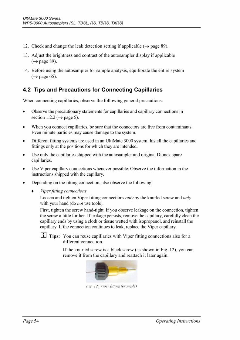
UltiMate 3000 Series: WPS-3000 Autosamplers (SL, TBSL, RS, TBRS, TXRS)
Page 54 Operating Instructions
12. Check and change the leak detection setting if applicable (→ page 89).
13. Adjust the brightness and contrast of the autosampler display if applicable (→ page 89).
14. Before using the autosampler for sample analysis, equilibrate the entire system (→ page 65).
4.2 Tips and Precautions for Connecting Capillaries
When connecting capillaries, observe the following general precautions:
• Observe the precautionary statements for capillaries and capillary connections in section 1.2.2 (→ page 5).
• When you connect capillaries, be sure that the connectors are free from contaminants. Even minute particles may cause damage to the system.
• Different fitting systems are used in an UltiMate 3000 system. Install the capillaries and fittings only at the positions for which they are intended.
• Use only the capillaries shipped with the autosampler and original Dionex spare capillaries.
• Use Viper capillary connections whenever possible. Observe the information in the instructions shipped with the capillary.
• Depending on the fitting connection, also observe the following:
♦ Viper fitting connections Loosen and tighten Viper fitting connections only by the knurled screw and only with your hand (do not use tools). First, tighten the screw hand-tight. If you observe leakage on the connection, tighten the screw a little further. If leakage persists, remove the capillary, carefully clean the capillary ends by using a cloth or tissue wetted with isopropanol, and reinstall the capillary. If the connection continues to leak, replace the Viper capillary.
Tips: You can reuse capillaries with Viper fitting connections also for a different connection.
If the knurled screw is a black screw (as shown in Fig. 12), you can remove it from the capillary and reattach it later again.
Fig. 12: Viper fitting (example)
UltiMate 3000 Series: WPS-3000 Autosamplers (SL, TBSL, RS, TBRS, TXRS)
Operating Instructions Page 55
♦ Conventional fitting connections (non-Viper) Do not overtighten these fitting connections. If you observe leakage on the connection, tighten a little further. If leakage still exists, first clean the connection port with a cleaning swab (part no. 6040.0006). Replace the capillary and/or fitting if this does not eliminate the problem. To avoid increased dead volume or damage to the system and leakage, reuse fittings and ferrules only for the same capillary connection.
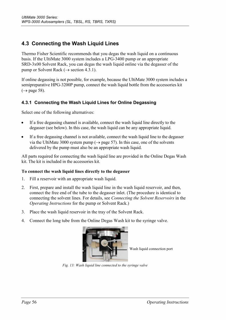
UltiMate 3000 Series: WPS-3000 Autosamplers (SL, TBSL, RS, TBRS, TXRS)
Page 56 Operating Instructions
4.3 Connecting the Wash Liquid Lines
Thermo Fisher Scientific recommends that you degas the wash liquid on a continuous basis. If the UltiMate 3000 system includes a LPG-3400 pump or an appropriate SRD-3x00 Solvent Rack, you can degas the wash liquid online via the degasser of the pump or Solvent Rack (→ section 4.3.1).
If online degassing is not possible, for example, because the UltiMate 3000 system includes a semipreparative HPG-3200P pump, connect the wash liquid bottle from the accessories kit (→ page 58).
4.3.1 Connecting the Wash Liquid Lines for Online Degassing
Select one of the following alternatives:
• If a free degassing channel is available, connect the wash liquid line directly to the degasser (see below). In this case, the wash liquid can be any appropriate liquid.
• If a free degassing channel is not available, connect the wash liquid line to the degasser via the UltiMate 3000 system pump (→ page 57). In this case, one of the solvents delivered by the pump must also be an appropriate wash liquid.
All parts required for connecting the wash liquid line are provided in the Online Degas Wash kit. The kit is included in the accessories kit.
To connect the wash liquid lines directly to the degasser 1. Fill a reservoir with an appropriate wash liquid.
2. First, prepare and install the wash liquid line in the wash liquid reservoir, and then, connect the free end of the tube to the degasser inlet. (The procedure is identical to connecting the solvent lines. For details, see Connecting the Solvent Reservoirs in the Operating Instructions for the pump or Solvent Rack.)
3. Place the wash liquid reservoir in the tray of the Solvent Rack.
4. Connect the long tube from the Online Degas Wash kit to the syringe valve.
Fig. 13: Wash liquid line connected to the syringe valve
Wash liquid connection port
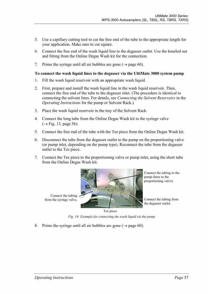
UltiMate 3000 Series: WPS-3000 Autosamplers (SL, TBSL, RS, TBRS, TXRS)
Operating Instructions Page 57
5. Use a capillary cutting tool to cut the free end of the tube to the appropriate length for your application. Make sure to cut square.
6. Connect the free end of the wash liquid line to the degasser outlet. Use the knurled nut and fitting from the Online Degas Wash kit for the connection.
7. Prime the syringe until all air bubbles are gone (→ page 60).
To connect the wash liquid lines to the degasser via the UltiMate 3000 system pump 1. Fill the wash liquid reservoir with an appropriate wash liquid.
2. First, prepare and install the wash liquid line in the wash liquid reservoir. Then, connect the free end of the tube to the degasser inlet. (The procedure is identical to connecting the solvent lines. For details, see Connecting the Solvent Reservoirs in the Operating Instructions for the pump or Solvent Rack.)
3. Place the wash liquid reservoir in the tray of the Solvent Rack.
4. Connect the long tube from the Online Degas Wash kit to the syringe valve (→ Fig. 13, page 56).
5. Connect the free end of the tube with the Tee piece from the Online Degas Wash kit.
6. Disconnect the tube from the degasser outlet to the pump on the proportioning valve (or pump inlet, depending on the pump type). Reconnect the tube from the degasser outlet to the Tee piece.
7. Connect the Tee piece to the proportioning valve or pump inlet, using the short tube from the Online Degas Wash kit.
Fig. 14: Example for connecting the wash liquid via the pump
8. Prime the syringe until all air bubbles are gone (→ page 60).
Connect the tubing to the pump (here to the proportioning valve)
Connect the tubing from the degasser outlet.
Connect the tubing from the syringe valve.
Tee piece
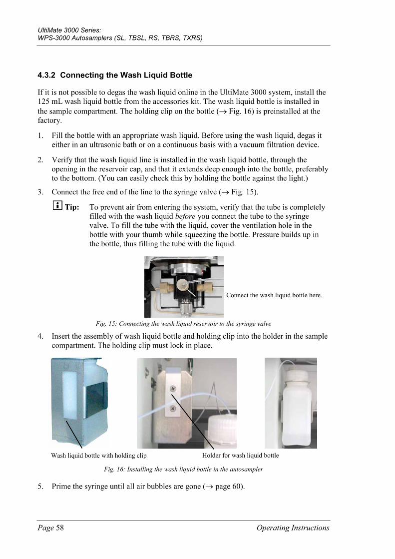
UltiMate 3000 Series: WPS-3000 Autosamplers (SL, TBSL, RS, TBRS, TXRS)
Page 58 Operating Instructions
4.3.2 Connecting the Wash Liquid Bottle
If it is not possible to degas the wash liquid online in the UltiMate 3000 system, install the 125 mL wash liquid bottle from the accessories kit. The wash liquid bottle is installed in the sample compartment. The holding clip on the bottle (→ Fig. 16) is preinstalled at the factory.
1. Fill the bottle with an appropriate wash liquid. Before using the wash liquid, degas it either in an ultrasonic bath or on a continuous basis with a vacuum filtration device.
2. Verify that the wash liquid line is installed in the wash liquid bottle, through the opening in the reservoir cap, and that it extends deep enough into the bottle, preferably to the bottom. (You can easily check this by holding the bottle against the light.)
3. Connect the free end of the line to the syringe valve (→ Fig. 15).
Tip: To prevent air from entering the system, verify that the tube is completely filled with the wash liquid before you connect the tube to the syringe valve. To fill the tube with the liquid, cover the ventilation hole in the bottle with your thumb while squeezing the bottle. Pressure builds up in the bottle, thus filling the tube with the liquid.
Fig. 15: Connecting the wash liquid reservoir to the syringe valve
4. Insert the assembly of wash liquid bottle and holding clip into the holder in the sample compartment. The holding clip must lock in place.
Wash liquid bottle with holding clip Holder for wash liquid bottle
Fig. 16: Installing the wash liquid bottle in the autosampler
5. Prime the syringe until all air bubbles are gone (→ page 60).
Connect the wash liquid bottle here.
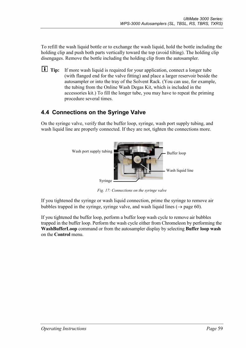
UltiMate 3000 Series: WPS-3000 Autosamplers (SL, TBSL, RS, TBRS, TXRS)
Operating Instructions Page 59
To refill the wash liquid bottle or to exchange the wash liquid, hold the bottle including the holding clip and push both parts vertically toward the top (avoid tilting). The holding clip disengages. Remove the bottle including the holding clip from the autosampler.
Tip: If more wash liquid is required for your application, connect a longer tube (with flanged end for the valve fitting) and place a larger reservoir beside the autosampler or into the tray of the Solvent Rack. (You can use, for example, the tubing from the Online Wash Degas Kit, which is included in the accessories kit.) To fill the longer tube, you may have to repeat the priming procedure several times.
4.4 Connections on the Syringe Valve
On the syringe valve, verify that the buffer loop, syringe, wash port supply tubing, and wash liquid line are properly connected. If they are not, tighten the connections more.
Buffer loop
Syringe
Wash liquid line
Wash port supply tubing
Fig. 17: Connections on the syringe valve
If you tightened the syringe or wash liquid connection, prime the syringe to remove air bubbles trapped in the syringe, syringe valve, and wash liquid lines (→ page 60).
If you tightened the buffer loop, perform a buffer loop wash cycle to remove air bubbles trapped in the buffer loop. Perform the wash cycle either from Chromeleon by performing the WashBufferLoop command or from the autosampler display by selecting Buffer loop wash on the Control menu.
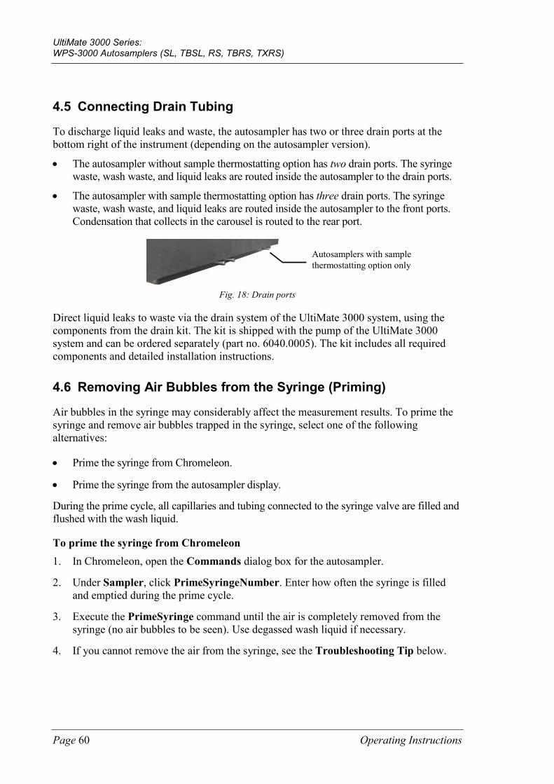
UltiMate 3000 Series: WPS-3000 Autosamplers (SL, TBSL, RS, TBRS, TXRS)
Page 60 Operating Instructions
4.5 Connecting Drain Tubing
To discharge liquid leaks and waste, the autosampler has two or three drain ports at the bottom right of the instrument (depending on the autosampler version).
• The autosampler without sample thermostatting option has two drain ports. The syringe waste, wash waste, and liquid leaks are routed inside the autosampler to the drain ports.
• The autosampler with sample thermostatting option has three drain ports. The syringe waste, wash waste, and liquid leaks are routed inside the autosampler to the front ports. Condensation that collects in the carousel is routed to the rear port.
Fig. 18: Drain ports
Direct liquid leaks to waste via the drain system of the UltiMate 3000 system, using the components from the drain kit. The kit is shipped with the pump of the UltiMate 3000 system and can be ordered separately (part no. 6040.0005). The kit includes all required components and detailed installation instructions.
4.6 Removing Air Bubbles from the Syringe (Priming)
Air bubbles in the syringe may considerably affect the measurement results. To prime the syringe and remove air bubbles trapped in the syringe, select one of the following alternatives:
• Prime the syringe from Chromeleon.
• Prime the syringe from the autosampler display.
During the prime cycle, all capillaries and tubing connected to the syringe valve are filled and flushed with the wash liquid.
To prime the syringe from Chromeleon 1. In Chromeleon, open the Commands dialog box for the autosampler.
2. Under Sampler, click PrimeSyringeNumber. Enter how often the syringe is filled and emptied during the prime cycle.
3. Execute the PrimeSyringe command until the air is completely removed from the syringe (no air bubbles to be seen). Use degassed wash liquid if necessary.
4. If you cannot remove the air from the syringe, see the Troubleshooting Tip below.
Autosamplers with sample thermostatting option only
UltiMate 3000 Series: WPS-3000 Autosamplers (SL, TBSL, RS, TBRS, TXRS)
Operating Instructions Page 61
To prime the syringe from the autosampler display 1. Show the function keys and select Prime.
2. Prime the syringe until the air is removed completely (no air bubbles to be seen). Use degassed wash liquid if necessary.
3. If you cannot remove the air from the syringe, see the Troubleshooting Tip below.
Troubleshooting Tip
1. Remove the syringe as described in Replacing the Syringe (→ page 120).
2. Fill a beaker with wash liquid or a mixture of isopropanol and water (50:50).
3. Place the threaded end of the syringe into the beaker.
4. Push the plunger completely into the syringe body and move the syringe several times rapidly to dislodge any air bubbles that might have gathered at the syringe inlet.
5. Fill the syringe several times completely. Push the plunger up and pull down rapidly with short movements to dislodge the bubbles.
6. Fill the syringe completely. Hold the syringe vertically and push a small amount of liquid out the top to make sure that no air is present.
7. Reinstall the syringe as described in Replacing the Syringe (→ page 120).
8. Perform a wash cycle from Chromeleon by selecting the Wash command or from the autosampler display by showing the function keys and selecting Wash or by selecting Wash on the Control menu.
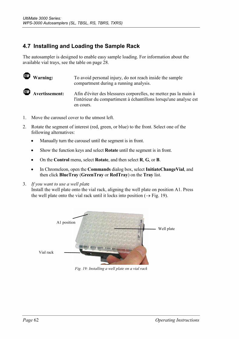
UltiMate 3000 Series: WPS-3000 Autosamplers (SL, TBSL, RS, TBRS, TXRS)
Page 62 Operating Instructions
4.7 Installing and Loading the Sample Rack
The autosampler is designed to enable easy sample loading. For information about the available vial trays, see the table on page 28.
Warning: To avoid personal injury, do not reach inside the sample compartment during a running analysis.
Avertissement: Afin d'éviter des blessures corporelles, ne mettez pas la main à l'intérieur du compartiment à échantillons lorsqu'une analyse est en cours.
1. Move the carousel cover to the utmost left.
2. Rotate the segment of interest (red, green, or blue) to the front. Select one of the following alternatives:
• Manually turn the carousel until the segment is in front.
• Show the function keys and select Rotate until the segment is in front.
• On the Control menu, select Rotate, and then select R, G, or B.
• In Chromeleon, open the Commands dialog box, select InitiateChangeVial, and then click BlueTray (GreenTray or RedTray) on the Tray list.
3. If you want to use a well plate Install the well plate onto the vial rack, aligning the well plate on position A1. Press the well plate onto the vial rack until it locks into position (→ Fig. 19).
Fig. 19: Installing a well plate on a vial rack
A1 position Well plate
Vial rack

UltiMate 3000 Series: WPS-3000 Autosamplers (SL, TBSL, RS, TBRS, TXRS)
Operating Instructions Page 63
4. Insert the vial tray (or the rack with well plate) in the carousel (→ Fig. 20). Make sure that the pins on the carousel bottom lock in the rack bottom.
Positioning pins in the carousel
Fig. 20: Top: Inserting a sample rack (here with well plate) Bottom: Carousel view (left: rack with well plate; right: rack with vials)
As a standard, each segment also accommodates one 5-position vial holder for 10 mL vials, such as reagent vials. If you operate the carousel as an exception without these holders, be sure to align the positioning bracket of the tray with the right end of the segment color.
Fig. 21: Sample rack alignment
5. Load the tray with the appropriate vials if applicable (→ page 29).
6. Move the carousel cover back to the right until contact is established to the needle arm.
7. When the autosampler is operated from Chromeleon
a) In Chromeleon, check and change the sample container settings for the three segments if necessary (→ page 87). The needle might be damaged if the installed sample containers do not match the settings in Chromeleon.
b) Adapt the SampleHeight if necessary (→ page 93). Pay special attention to the information about SampleHeightOffset on page 94.
Correct alignment
UltiMate 3000 Series: WPS-3000 Autosamplers (SL, TBSL, RS, TBRS, TXRS)
Page 64 Operating Instructions
4.8 Loading the 5-Position Vial Holder
When the autosampler is shipped, each color-coded segment in the carousel also accommodates one 5-position vial holder for 10 mL vials, for example, reagent vials. Load the holders with the appropriate 10 mL vials (→ page 29).
As an alternative, you can load the holders also with 2 mL vials. In this case, you have to install the adapter (part no. 6820.4092) first.
Warning: To avoid personal injury, do not reach inside the sample compartment during a running analysis.
Avertissement: Afin d'éviter des blessures corporelles, ne mettez pas la main à l'intérieur du compartiment à échantillons lorsqu'une analyse est en cours.
1. Move the carousel cover to the utmost left.
2. Rotate the segment of interest (red, green, or blue) to the front. Select one of the following alternatives:
• Manually turn the carousel until the segment is in front. • Show the function keys and select Rotate until the holder is in front. • On the Control menu, select Rotate, and then select R, G, or B. • In Chromeleon, open the Commands dialog box, select InitiateChangeVial, and
then click BlueVials (GreenVials or RedVials) on the Tray list.
3. Load the holder with the appropriate vials (10 mL or 2 mL) (→ page 29).
4. Move the carousel cover back to the right until contact is established to the needle arm.
5. If the autosampler is operated from Chromeleon Check and adapt the ReagentLiquidHeight if necessary (→ page 93). Pay special attention to the information about SampleHeightOffset on page 94. If you are using 2 mL vials, you have to adapt the value for SampleHeightOffset_T (→ page 94) to avoid damage to the needle.
When loading the vial holder, install vials of the same type in all five positions.
UltiMate 3000 Series: WPS-3000 Autosamplers (SL, TBSL, RS, TBRS, TXRS)
Operating Instructions Page 65
4.9 Equilibrating the System
Before using the autosampler for sample analysis, equilibrate the UltiMate 3000 system:
1. Pump the starting solvent through the entire system until the system is free of any other liquid composition.
2. Heat or cool all temperature-controlled devices to the temperature required for the application.
3. Set the detector wavelengths and turn on the lamps.
4. Monitor the pump pressure and verify that the reading is correct for the application and is stable.
5. Monitor the detector signal and verify that the baseline signal is at the expected reading for your application and is stable.
Perform system equilibration in Chromeleon or select the required commands and parameters on the front panel menus of the instruments.
To equilibrate the system from Chromeleon
• Select and perform the operating commands and parameters from the Commands dialog box.
• Create and run an equilibration program to automate the process (→ page 75).
• Use the SmartStartup Wizard to create and run the equilibration program (see below).
To create the equilibration program with the SmartStartup Wizard The SmartStartup Wizard in Chromeleon guides you through the process of creating and running an equilibration program.
1. To open the wizard, select SmartStartup on the Batch menu.
2. Follow the instructions as they appear on each page of the wizard. For additional information about a page, click Help.
3. After you finish the wizard, Chromeleon
♦ Generates an equilibration program and sequence ♦ Opens the equilibration control panel for the instruments in the timebase (→ Fig. 22,
page 66) ♦ Opens the Start Batch on dialog box Click Start to begin equilibration.
The equilibration panel shows the equilibration status of each instrument in the system.
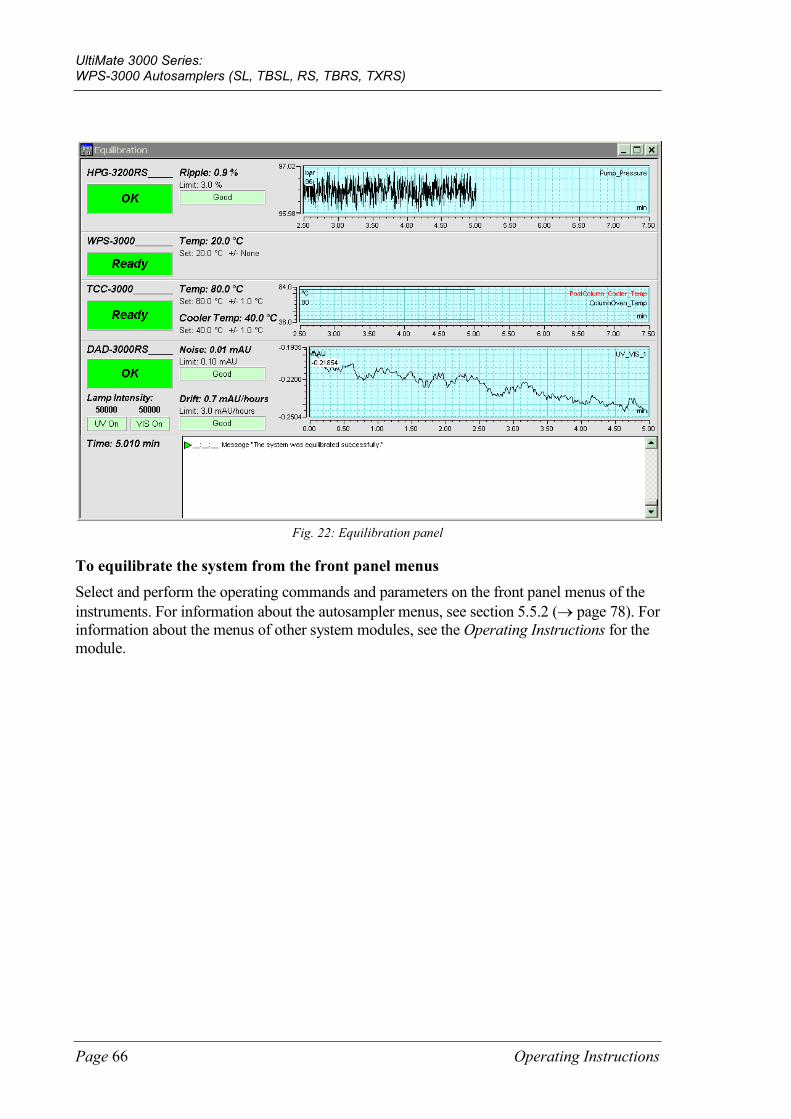
UltiMate 3000 Series: WPS-3000 Autosamplers (SL, TBSL, RS, TBRS, TXRS)
Page 66 Operating Instructions
Fig. 22: Equilibration panel
To equilibrate the system from the front panel menus Select and perform the operating commands and parameters on the front panel menus of the instruments. For information about the autosampler menus, see section 5.5.2 (→ page 78). For information about the menus of other system modules, see the Operating Instructions for the module.
UltiMate 3000 Series: WPS-3000 Autosamplers (SL, TBSL, RS, TBRS, TXRS)
Operating Instructions Page 67
5 Operation and Maintenance The autosampler can be controlled from the Chromeleon Chromatography Management System. For details, see section 5.4 (→ page 71).
In addition, function keys and menus on the autosampler display allow you to perform certain actions directly from the autosampler, for example during initial installation or for diagnostics and maintenance work. For example, you can
• Perform certain functions (rotate the carousel)
• Execute certain commands (wash, approach service positions)
• Set parameters (leak sensor mode, target temperature for sample thermostatting)
• View diagnostic information
• View and change the autosampler configuration
For details, see section 5.5 (→ page 77).
5.1 Power-Up
To start the autosampler for the first time, turn on the main power switch on the rear panel of the autosampler. The following sequence of events occurs when the autosampler is powered up:
• For a short time, general information about the autosampler appears on the autosampler display: device type, serial number, bootloader and firmware versions.
• The autosampler runs a series of internal tests during which all of the main components are checked. When testing is complete and has been successful, the initial screen changes to the status screen (→ page 68).
• If an error is detected, the autosampler is not ready for analysis. The Status LED on the front panel changes to red and a message appears on the autosampler display. If the autosampler is operated from Chromeleon, the message is logged also in the Chromeleon Audit Trail. Turn off the autosampler, take appropriate remedial action (→ page 103), and turn on the autosampler again.
For routine operation, leave the main power switch on. For routine on/off control, use the standby button on the front of the autosampler (→ page 24). Press and hold the button for one second to allow the autosampler to change the mode. Turn the main power switch off when instructed to do so, for example, before performing a service procedure.
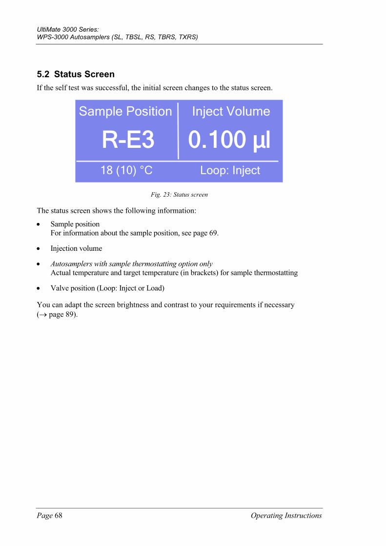
UltiMate 3000 Series: WPS-3000 Autosamplers (SL, TBSL, RS, TBRS, TXRS)
Page 68 Operating Instructions
5.2 Status Screen If the self test was successful, the initial screen changes to the status screen.
Sample Position
R-E3 Inject Volume
0.100 µl 18 (10) °C Loop: Inject
Fig. 23: Status screen
The status screen shows the following information:
• Sample position For information about the sample position, see page 69.
• Injection volume
• Autosamplers with sample thermostatting option only Actual temperature and target temperature (in brackets) for sample thermostatting
• Valve position (Loop: Inject or Load)
You can adapt the screen brightness and contrast to your requirements if necessary (→ page 89).
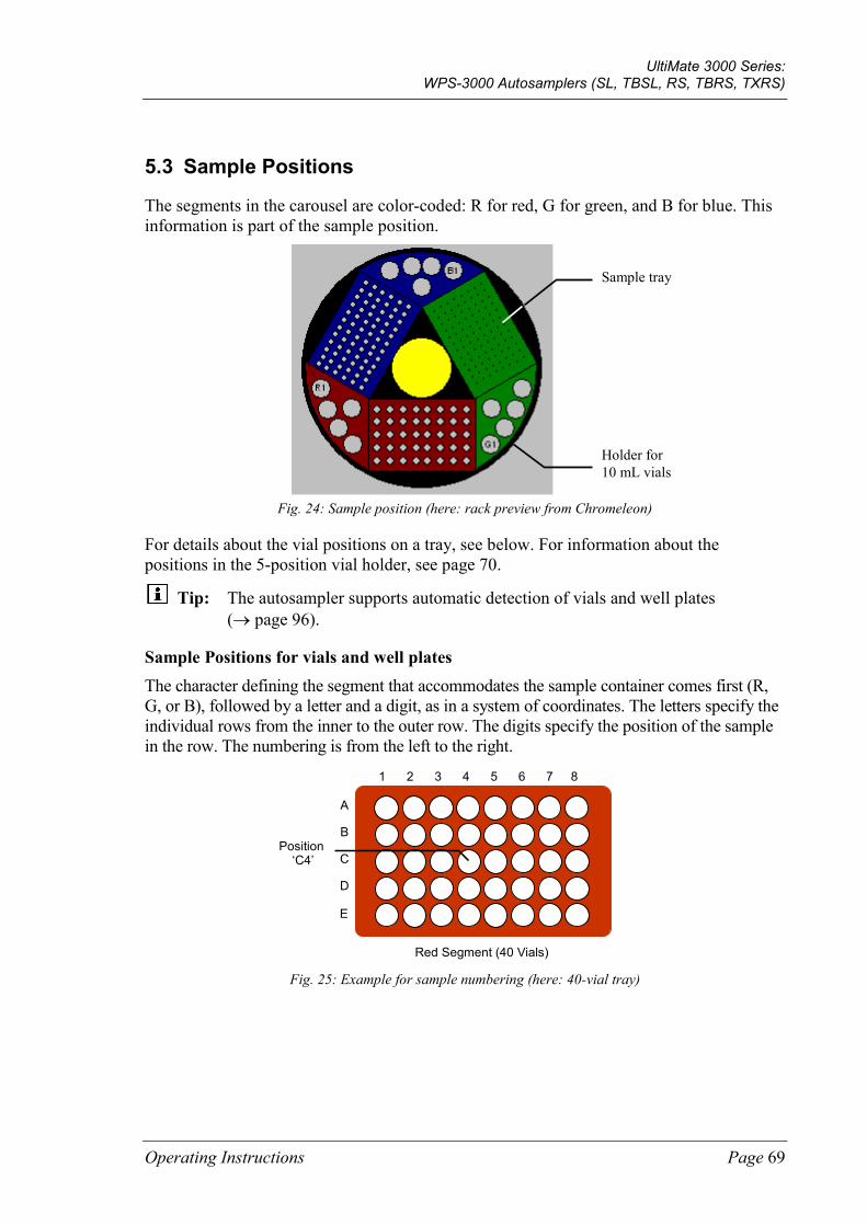
UltiMate 3000 Series: WPS-3000 Autosamplers (SL, TBSL, RS, TBRS, TXRS)
Operating Instructions Page 69
5.3 Sample Positions
The segments in the carousel are color-coded: R for red, G for green, and B for blue. This information is part of the sample position.
Fig. 24: Sample position (here: rack preview from Chromeleon)
For details about the vial positions on a tray, see below. For information about the positions in the 5-position vial holder, see page 70.
Tip: The autosampler supports automatic detection of vials and well plates (→ page 96).
Sample Positions for vials and well plates The character defining the segment that accommodates the sample container comes first (R, G, or B), followed by a letter and a digit, as in a system of coordinates. The letters specify the individual rows from the inner to the outer row. The digits specify the position of the sample in the row. The numbering is from the left to the right.
1 2 3 4 5 6 7 8
C
A
B
E
D
Red Segment (40 Vials)
Position ‘C4’
Fig. 25: Example for sample numbering (here: 40-vial tray)
Holder for 10 mL vials
Sample tray
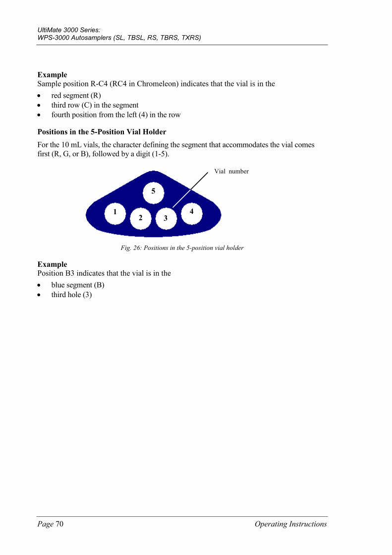
UltiMate 3000 Series: WPS-3000 Autosamplers (SL, TBSL, RS, TBRS, TXRS)
Page 70 Operating Instructions
Example Sample position R-C4 (RC4 in Chromeleon) indicates that the vial is in the • red segment (R) • third row (C) in the segment • fourth position from the left (4) in the row
Positions in the 5-Position Vial Holder For the 10 mL vials, the character defining the segment that accommodates the vial comes first (R, G, or B), followed by a digit (1-5).
5
1 3
4 2
Vial number
Fig. 26: Positions in the 5-position vial holder
Example Position B3 indicates that the vial is in the • blue segment (B) • third hole (3)
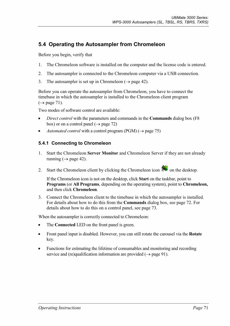
UltiMate 3000 Series: WPS-3000 Autosamplers (SL, TBSL, RS, TBRS, TXRS)
Operating Instructions Page 71
5.4 Operating the Autosampler from Chromeleon
Before you begin, verify that
1. The Chromeleon software is installed on the computer and the license code is entered.
2. The autosampler is connected to the Chromeleon computer via a USB connection.
3. The autosampler is set up in Chromeleon (→ page 42).
Before you can operate the autosampler from Chromeleon, you have to connect the timebase in which the autosampler is installed to the Chromeleon client program (→ page 71).
Two modes of software control are available:
• Direct control with the parameters and commands in the Commands dialog box (F8 box) or on a control panel (→ page 72)
• Automated control with a control program (PGM) (→ page 75)
5.4.1 Connecting to Chromeleon
1. Start the Chromeleon Server Monitor and Chromeleon Server if they are not already running (→ page 42).
2. Start the Chromeleon client by clicking the Chromeleon icon on the desktop.
If the Chromeleon icon is not on the desktop, click Start on the taskbar, point to Programs (or All Programs, depending on the operating system), point to Chromeleon, and then click Chromeleon.
3. Connect the Chromeleon client to the timebase in which the autosampler is installed. For details about how to do this from the Commands dialog box, see page 72. For details about how to do this on a control panel, see page 73.
When the autosampler is correctly connected to Chromeleon:
• The Connected LED on the front panel is green.
• Front panel input is disabled. However, you can still rotate the carousel via the Rotate key.
• Functions for estimating the lifetime of consumables and monitoring and recording service and (re)qualification information are provided (→ page 91).
UltiMate 3000 Series: WPS-3000 Autosamplers (SL, TBSL, RS, TBRS, TXRS)
Page 72 Operating Instructions
• Diagnostic tests are provided to check the performance of certain autosampler components and the overall performance of the instrument (→ page 92).
• The Standby button on the front panel remains active.
Before turning off the autosampler by the main power switch, always disconnect the module in Chromeleon.
5.4.2 Direct Control
With direct control, you select operating parameters and commands in the Commands (F8) dialog box. Direct commands are executed as soon as they are entered. For routine operation, most parameters and commands are available also on a control panel.
To open the Commands dialog box for the autosampler 1. Open a control panel (any panel is possible). Open the Chromeleon Browser and
double-click a control panel in the Dionex Templates/Panels folder.
2. Connect the control panel to the timebase in which the autosampler is installed. On the Control menu, select Connect to Timebase, and then select the timebase on the Timebase tab. For information about the Timebase dialog, click Help.
Tip: The Control menu is visible only when a control panel is already open.
3. Press the F8 key or select Command on the Control menu.
4. To see the parameters and commands that are available for the autosampler, click the plus sign beside Sampler.
The commands and parameters that are available in the dialog box vary, depending on the
♦ Chromeleon version
♦ Options selected in the Properties dialog for the autosampler (→ page 45)
♦ Display filter level (Normal, Advanced, or Expert)
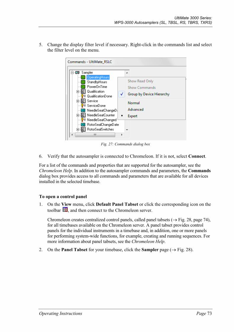
UltiMate 3000 Series: WPS-3000 Autosamplers (SL, TBSL, RS, TBRS, TXRS)
Operating Instructions Page 73
5. Change the display filter level if necessary. Right-click in the commands list and select the filter level on the menu.
Fig. 27: Commands dialog box
6. Verify that the autosampler is connected to Chromeleon. If it is not, select Connect.
For a list of the commands and properties that are supported for the autosampler, see the Chromeleon Help. In addition to the autosampler commands and parameters, the Commands dialog box provides access to all commands and parameters that are available for all devices installed in the selected timebase.
To open a control panel 1. On the View menu, click Default Panel Tabset or click the corresponding icon on the
toolbar , and then connect to the Chromeleon server.
Chromeleon creates centralized control panels, called panel tabsets (→ Fig. 28, page 74), for all timebases available on the Chromeleon server. A panel tabset provides control panels for the individual instruments in a timebase and, in addition, one or more panels for performing system-wide functions, for example, creating and running sequences. For more information about panel tabsets, see the Chromeleon Help.
2. On the Panel Tabset for your timebase, click the Sampler page (→ Fig. 28).
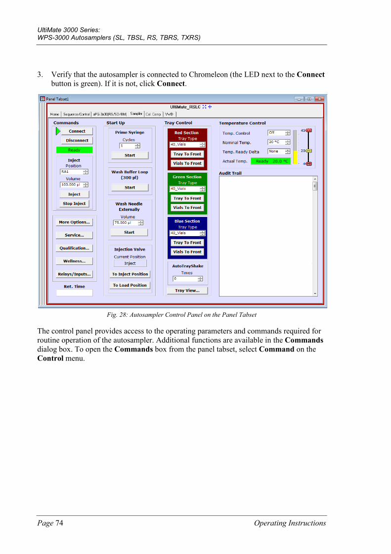
UltiMate 3000 Series: WPS-3000 Autosamplers (SL, TBSL, RS, TBRS, TXRS)
Page 74 Operating Instructions
3. Verify that the autosampler is connected to Chromeleon (the LED next to the Connect button is green). If it is not, click Connect.
Fig. 28: Autosampler Control Panel on the Panel Tabset
The control panel provides access to the operating parameters and commands required for routine operation of the autosampler. Additional functions are available in the Commands dialog box. To open the Commands box from the panel tabset, select Command on the Control menu.
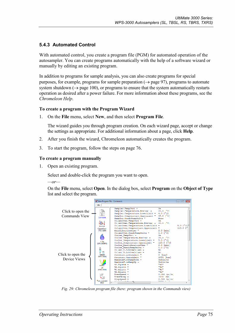
UltiMate 3000 Series: WPS-3000 Autosamplers (SL, TBSL, RS, TBRS, TXRS)
Operating Instructions Page 75
5.4.3 Automated Control
With automated control, you create a program file (PGM) for automated operation of the autosampler. You can create programs automatically with the help of a software wizard or manually by editing an existing program.
In addition to programs for sample analysis, you can also create programs for special purposes, for example, programs for sample preparation (→ page 97), programs to automate system shutdown (→ page 100), or programs to ensure that the system automatically restarts operation as desired after a power failure. For more information about these programs, see the Chromeleon Help.
To create a program with the Program Wizard 1. On the File menu, select New, and then select Program File.
The wizard guides you through program creation. On each wizard page, accept or change the settings as appropriate. For additional information about a page, click Help.
2. After you finish the wizard, Chromeleon automatically creates the program.
3. To start the program, follow the steps on page 76.
To create a program manually 1. Open an existing program.
Select and double-click the program you want to open. —or— On the File menu, select Open. In the dialog box, select Program on the Object of Type list and select the program.
Fig. 29: Chromeleon program file (here: program shown in the Commands view)
Click to open the Commands View
Click to open the Device Views
UltiMate 3000 Series: WPS-3000 Autosamplers (SL, TBSL, RS, TBRS, TXRS)
Page 76 Operating Instructions
2. Change the program settings as needed.
The easiest way is to edit a program in the Device Views (→ Fig. 29). Click a device icon and change the settings on the device pages. Editing the program in the Device Views ensures correct command syntax.
If you cannot edit a certain parameter in the Device View, click Commands to open the Commands View. The Commands View shows the entire program, listing the control commands in chronological order. Edit the parameter of interest or enter a new parameter. For more information, see the Chromeleon Help.
3. To start the program, follow the steps below.
To start a program Program for sample analysis 1. Create a sample list (sequence). A sequence must include the program and a method
for evaluating the sample data (for example, for peak identification, area determination, and amount determination).
2. Assign the program and method to each sample on the list.
3. Add the sequence to the batch and start the batch.
For information about each of the above steps, see the Chromeleon Help.
Other programs Add the program to the batch and start the batch.
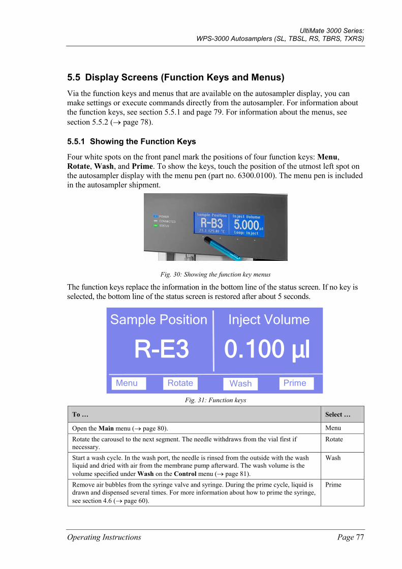
UltiMate 3000 Series: WPS-3000 Autosamplers (SL, TBSL, RS, TBRS, TXRS)
Operating Instructions Page 77
5.5 Display Screens (Function Keys and Menus) Via the function keys and menus that are available on the autosampler display, you can make settings or execute commands directly from the autosampler. For information about the function keys, see section 5.5.1 and page 79. For information about the menus, see section 5.5.2 (→ page 78).
5.5.1 Showing the Function Keys
Four white spots on the front panel mark the positions of four function keys: Menu, Rotate, Wash, and Prime. To show the keys, touch the position of the utmost left spot on the autosampler display with the menu pen (part no. 6300.0100). The menu pen is included in the autosampler shipment.
Fig. 30: Showing the function key menus
The function keys replace the information in the bottom line of the status screen. If no key is selected, the bottom line of the status screen is restored after about 5 seconds.
Sample Position
R-E3 Inject Volume
0.100 µl Menu Rotate Wash Prime
Fig. 31: Function keys
To … Select …
Open the Main menu (→ page 80). Menu
Rotate the carousel to the next segment. The needle withdraws from the vial first if necessary.
Rotate
Start a wash cycle. In the wash port, the needle is rinsed from the outside with the wash liquid and dried with air from the membrane pump afterward. The wash volume is the volume specified under Wash on the Control menu (→ page 81).
Wash
Remove air bubbles from the syringe valve and syringe. During the prime cycle, liquid is drawn and dispensed several times. For more information about how to prime the syringe, see section 4.6 (→ page 60).
Prime
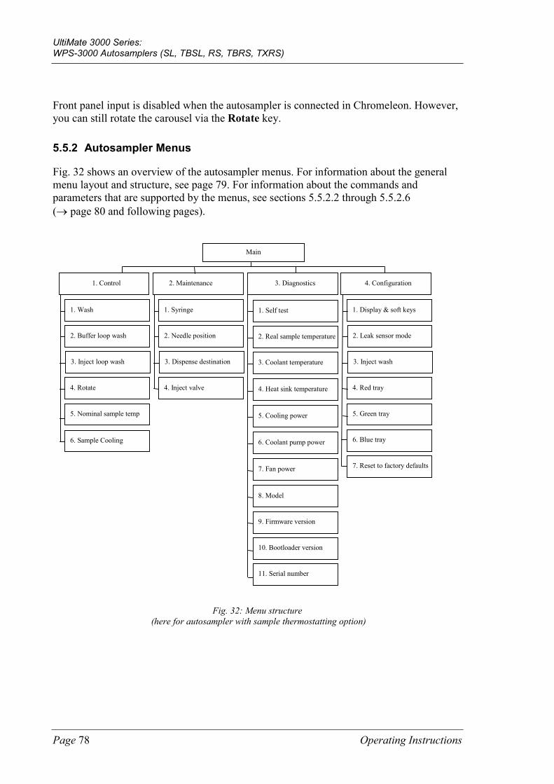
UltiMate 3000 Series: WPS-3000 Autosamplers (SL, TBSL, RS, TBRS, TXRS)
Page 78 Operating Instructions
Front panel input is disabled when the autosampler is connected in Chromeleon. However, you can still rotate the carousel via the Rotate key.
5.5.2 Autosampler Menus
Fig. 32 shows an overview of the autosampler menus. For information about the general menu layout and structure, see page 79. For information about the commands and parameters that are supported by the menus, see sections 5.5.2.2 through 5.5.2.6 (→ page 80 and following pages).
1. Control 2. Maintenance 3. Diagnostics
Main
1. Self test
2. Real sample temperature
3. Coolant temperature
4. Heat sink temperature
5. Cooling power
6. Coolant pump power
7. Fan power
8. Model
1. Syringe
2. Needle position
3. Dispense destination
4. Inject valve
1. Wash
2. Buffer loop wash
3. Inject loop wash
4. Rotate
4. Configuration
1. Display & soft keys
2. Leak sensor mode
3. Inject wash
4. Red tray
5. Green tray
6. Blue tray
7. Reset to factory defaults
9. Firmware version
10. Bootloader version
11. Serial number
5. Nominal sample temp
6. Sample Cooling
Fig. 32: Menu structure (here for autosampler with sample thermostatting option)
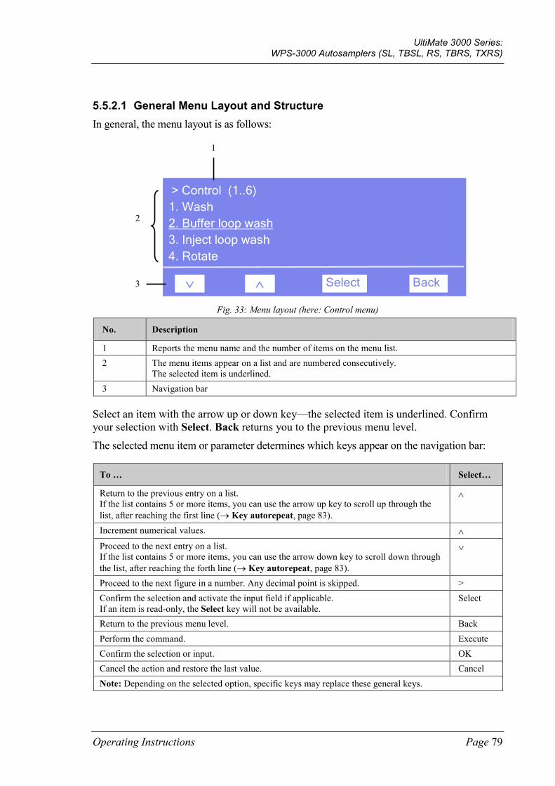
UltiMate 3000 Series: WPS-3000 Autosamplers (SL, TBSL, RS, TBRS, TXRS)
Operating Instructions Page 79
5.5.2.1 General Menu Layout and Structure In general, the menu layout is as follows:
∧
> Control (1..6) 1. Wash 2. Buffer loop wash 3. Inject loop wash 4. Rotate
∨ Select Back
1
2
3
Fig. 33: Menu layout (here: Control menu)
No. Description
1 Reports the menu name and the number of items on the menu list. 2 The menu items appear on a list and are numbered consecutively.
The selected item is underlined. 3 Navigation bar
Select an item with the arrow up or down key—the selected item is underlined. Confirm your selection with Select. Back returns you to the previous menu level.
The selected menu item or parameter determines which keys appear on the navigation bar:
To … Select…
Return to the previous entry on a list. If the list contains 5 or more items, you can use the arrow up key to scroll up through the list, after reaching the first line (→ Key autorepeat, page 83).
∧
Increment numerical values. ∧ Proceed to the next entry on a list. If the list contains 5 or more items, you can use the arrow down key to scroll down through the list, after reaching the forth line (→ Key autorepeat, page 83).
∨
Proceed to the next figure in a number. Any decimal point is skipped. > Confirm the selection and activate the input field if applicable. If an item is read-only, the Select key will not be available.
Select
Return to the previous menu level. Back Perform the command. Execute Confirm the selection or input. OK Cancel the action and restore the last value. Cancel Note: Depending on the selected option, specific keys may replace these general keys.
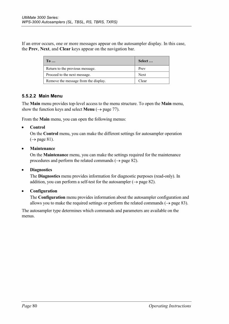
UltiMate 3000 Series: WPS-3000 Autosamplers (SL, TBSL, RS, TBRS, TXRS)
Page 80 Operating Instructions
If an error occurs, one or more messages appear on the autosampler display. In this case, the Prev, Next, and Clear keys appear on the navigation bar.
To … Select …
Return to the previous message. Prev Proceed to the next message. Next Remove the message from the display. Clear
5.5.2.2 Main Menu The Main menu provides top-level access to the menu structure. To open the Main menu, show the function keys and select Menu (→ page 77).
From the Main menu, you can open the following menus:
• Control On the Control menu, you can make the different settings for autosampler operation (→ page 81).
• Maintenance On the Maintenance menu, you can make the settings required for the maintenance procedures and perform the related commands (→ page 82).
• Diagnostics The Diagnostics menu provides information for diagnostic purposes (read-only). In addition, you can perform a self-test for the autosampler (→ page 82).
• Configuration The Configuration menu provides information about the autosampler configuration and allows you to make the required settings or perform the related commands (→ page 83).
The autosampler type determines which commands and parameters are available on the menus.
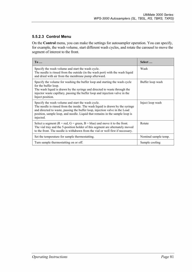
UltiMate 3000 Series: WPS-3000 Autosamplers (SL, TBSL, RS, TBRS, TXRS)
Operating Instructions Page 81
5.5.2.3 Control Menu On the Control menu, you can make the settings for autosampler operation. You can specify, for example, the wash volume, start different wash cycles, and rotate the carousel to move the segment of interest to the front.
To … Select …
Specify the wash volume and start the wash cycle. The needle is rinsed from the outside (in the wash port) with the wash liquid and dried with air from the membrane pump afterward.
Wash
Specify the volume for washing the buffer loop and starting the wash cycle for the buffer loop. The wash liquid is drawn by the syringe and directed to waste through the injector waste capillary, passing the buffer loop and injection valve in the Inject position.
Buffer loop wash
Specify the wash volume and start the wash cycle. The needle is rinsed from the inside. The wash liquid is drawn by the syringe and directed to waste, passing the buffer loop, injection valve in the Load position, sample loop, and needle. Liquid that remains in the sample loop is injected.
Inject loop wash
Select a segment (R = red, G = green, B = blue) and move it to the front. The vial tray and the 5-position holder of this segment are alternately moved to the front. The needle is withdrawn from the vial or well first if necessary.
Rotate
Set the temperature for sample thermostatting. Nominal sample temp.
Turn sample thermostatting on or off. Sample cooling
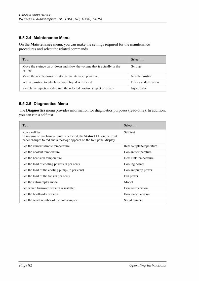
UltiMate 3000 Series: WPS-3000 Autosamplers (SL, TBSL, RS, TBRS, TXRS)
Page 82 Operating Instructions
5.5.2.4 Maintenance Menu On the Maintenance menu, you can make the settings required for the maintenance procedures and select the related commands.
To … Select …
Move the syringe up or down and show the volume that is actually in the syringe.
Syringe
Move the needle down or into the maintenance position. Needle position
Set the position to which the wash liquid is directed. Dispense destination
Switch the injection valve into the selected position (Inject or Load). Inject valve
5.5.2.5 Diagnostics Menu The Diagnostics menu provides information for diagnostics purposes (read-only). In addition, you can run a self test.
To … Select …
Run a self test. If an error or mechanical fault is detected, the Status LED on the front panel changes to red and a message appears on the font panel display
Self test
See the current sample temperature. Real sample temperature
See the coolant temperature. Coolant temperature
See the heat sink temperature. Heat sink temperature
See the load of cooling power (in per cent). Cooling power
See the load of the cooling pump (in per cent). Coolant pump power
See the load of the fan (in per cent). Fan power
See the autosampler model. Model
See which firmware version is installed. Firmware version
See the bootloader version. Bootloader version
See the serial number of the autosampler. Serial number
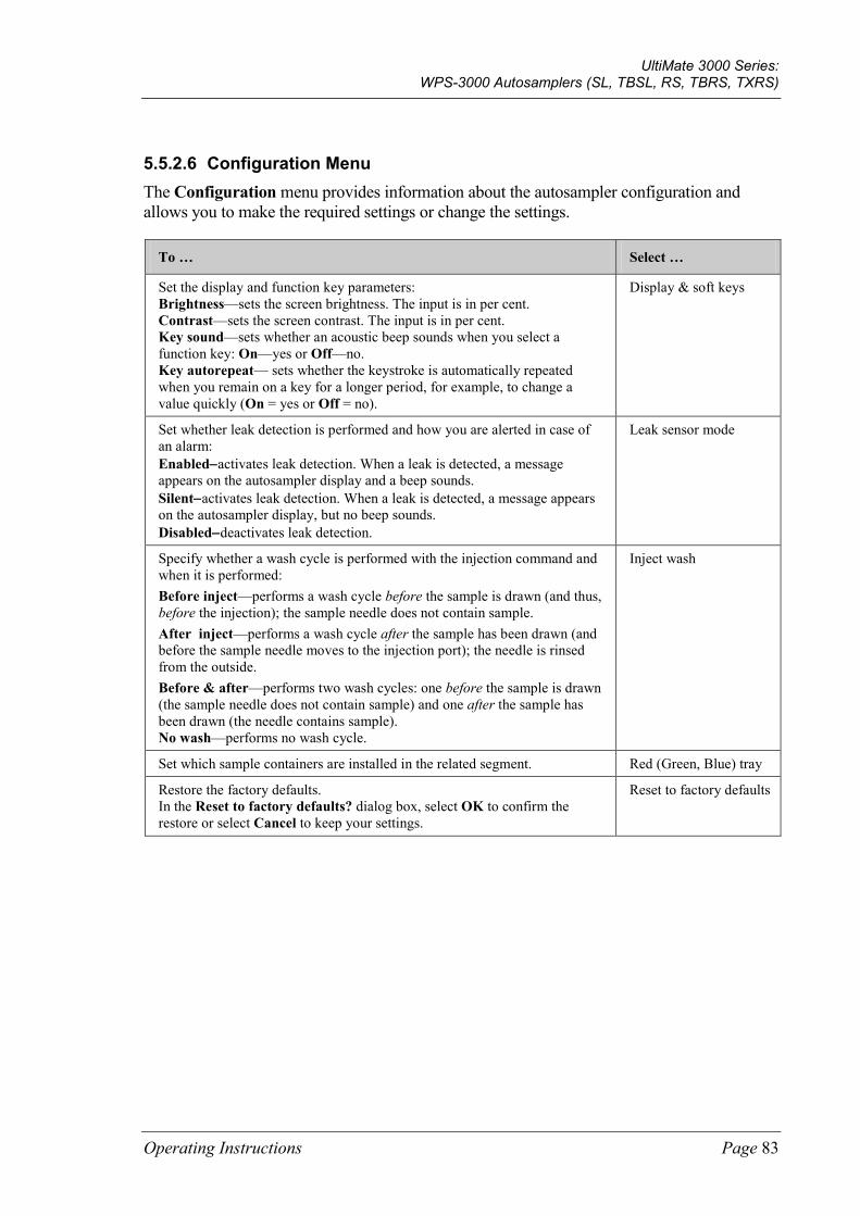
UltiMate 3000 Series: WPS-3000 Autosamplers (SL, TBSL, RS, TBRS, TXRS)
Operating Instructions Page 83
5.5.2.6 Configuration Menu The Configuration menu provides information about the autosampler configuration and allows you to make the required settings or change the settings.
To … Select …
Set the display and function key parameters: Brightness—sets the screen brightness. The input is in per cent. Contrast—sets the screen contrast. The input is in per cent. Key sound—sets whether an acoustic beep sounds when you select a function key: On—yes or Off—no. Key autorepeat— sets whether the keystroke is automatically repeated when you remain on a key for a longer period, for example, to change a value quickly (On = yes or Off = no).
Display & soft keys
Set whether leak detection is performed and how you are alerted in case of an alarm: Enabled−activates leak detection. When a leak is detected, a message appears on the autosampler display and a beep sounds. Silent−activates leak detection. When a leak is detected, a message appears on the autosampler display, but no beep sounds. Disabled−deactivates leak detection.
Leak sensor mode
Specify whether a wash cycle is performed with the injection command and when it is performed: Before inject—performs a wash cycle before the sample is drawn (and thus, before the injection); the sample needle does not contain sample. After inject—performs a wash cycle after the sample has been drawn (and before the sample needle moves to the injection port); the needle is rinsed from the outside. Before & after—performs two wash cycles: one before the sample is drawn (the sample needle does not contain sample) and one after the sample has been drawn (the needle contains sample). No wash—performs no wash cycle.
Inject wash
Set which sample containers are installed in the related segment. Red (Green, Blue) tray
Restore the factory defaults. In the Reset to factory defaults? dialog box, select OK to confirm the restore or select Cancel to keep your settings.
Reset to factory defaults
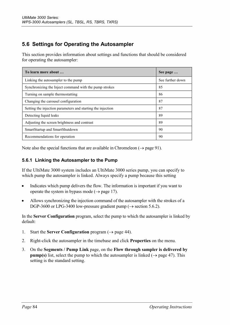
UltiMate 3000 Series: WPS-3000 Autosamplers (SL, TBSL, RS, TBRS, TXRS)
Page 84 Operating Instructions
5.6 Settings for Operating the Autosampler
This section provides information about settings and functions that should be considered for operating the autosampler:
To learn more about … See page …
Linking the autosampler to the pump See further down
Synchronizing the Inject command with the pump strokes 85
Turning on sample thermostatting 86
Changing the carousel configuration 87
Setting the injection parameters and starting the injection 87
Detecting liquid leaks 89
Adjusting the screen brightness and contrast 89
SmartStartup and SmartShutdown 90
Recommendations for operation 90
Note also the special functions that are available in Chromeleon (→ page 91).
5.6.1 Linking the Autosampler to the Pump
If the UltiMate 3000 system includes an UltiMate 3000 series pump, you can specify to which pump the autosampler is linked. Always specify a pump because this setting
• Indicates which pump delivers the flow. The information is important if you want to operate the system in bypass mode (→ page 17).
• Allows synchronizing the injection command of the autosampler with the strokes of a DGP-3600 or LPG-3400 low-pressure gradient pump (→ section 5.6.2).
In the Server Configuration program, select the pump to which the autosampler is linked by default:
1. Start the Server Configuration program (→ page 44).
2. Right-click the autosampler in the timebase and click Properties on the menu.
3. On the Segments / Pump Link page, on the Flow through sampler is delivered by pump(s) list, select the pump to which the autosampler is linked (→ page 47). This setting is the standard setting.
UltiMate 3000 Series: WPS-3000 Autosamplers (SL, TBSL, RS, TBRS, TXRS)
Operating Instructions Page 85
5.6.2 Synchronizing the Inject Command with the Pump Strokes
Only if the UltiMate 3000 system includes a DGP-3600 or LPG-3400
Tip: If you want to link a LPG-3400XRS pump or if you want to link a LPG-3400XRS and a second pump to the autosampler, see the Operating Instructions for the LPG-3400XRS pump for a detailed description of the required settings.
Synchronization of the time of injection with the strokes of the pump will be possible only when you link the autosampler to a DGP-3600 or LPG-3400 pump in the Chromeleon Server Configuration program (→ section 5.6.1). Synchronization ensures that all injections are performed at the same phase of the pump cycle, enhancing the retention time precision with gradient applications.
In the Commands dialog box, in a program, or on the control panel for the autosampler (under More Options), you can set whether you want or do not want to use synchronization and you can select a different pump.
• If you do not want to use synchronization, set SyncWithPump to Off .
• Pump Device shows the name of the pump with which synchronization will be performed. If you want to use a different pump, type the name of the pump in the input field. (Use the name specified for the pump in the Server Configuration program.) Verify that SyncWithPump is set to On.
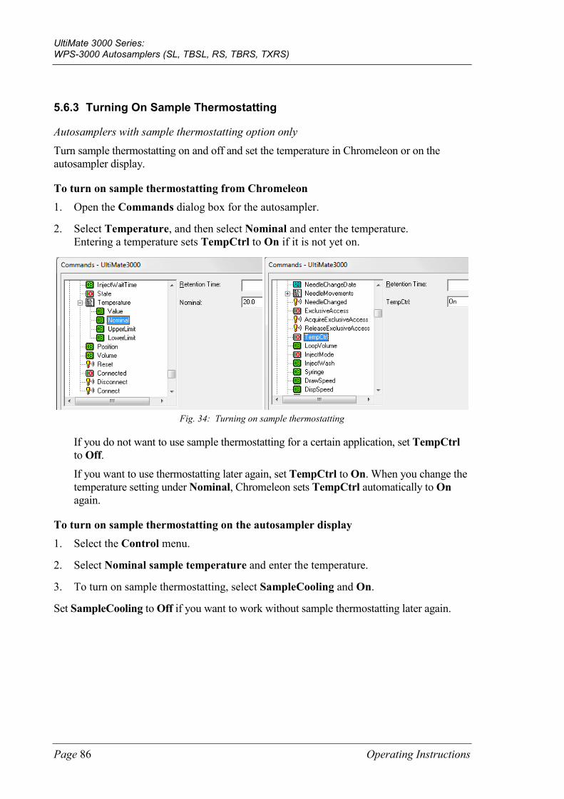
UltiMate 3000 Series: WPS-3000 Autosamplers (SL, TBSL, RS, TBRS, TXRS)
Page 86 Operating Instructions
5.6.3 Turning On Sample Thermostatting
Autosamplers with sample thermostatting option only Turn sample thermostatting on and off and set the temperature in Chromeleon or on the autosampler display.
To turn on sample thermostatting from Chromeleon 1. Open the Commands dialog box for the autosampler.
2. Select Temperature, and then select Nominal and enter the temperature. Entering a temperature sets TempCtrl to On if it is not yet on.
Fig. 34: Turning on sample thermostatting
If you do not want to use sample thermostatting for a certain application, set TempCtrl to Off. If you want to use thermostatting later again, set TempCtrl to On. When you change the temperature setting under Nominal, Chromeleon sets TempCtrl automatically to On again.
To turn on sample thermostatting on the autosampler display 1. Select the Control menu.
2. Select Nominal sample temperature and enter the temperature.
3. To turn on sample thermostatting, select SampleCooling and On.
Set SampleCooling to Off if you want to work without sample thermostatting later again.
UltiMate 3000 Series: WPS-3000 Autosamplers (SL, TBSL, RS, TBRS, TXRS)
Operating Instructions Page 87
5.6.4 Changing the Carousel Configuration
During initial installation of the autosampler in Chromeleon, the standard configuration of the carousel is specified on the Segments / Pump Link page in the Chromeleon Server Configuration program. If you later install different sample containers, you have to update the settings in Chromeleon accordingly:
• If you want to update the standard configuration Update the settings on the Segments / Pump Link page in the Chromeleon Server Configuration program (→ page 46).
• If you do not want to change the standard configuration, update the settings in the Chromeleon Client program
Select one of the following alternatives:
♦ Open the Commands dialog box, select RedTray, GreenTray, or BlueTray, and click the new sample containers on the input list.
♦ Open the control panel for the autosampler. Under Red Section, Green Section, or Blue Section, click the new sample containers on the Tray Type list.
If the settings in Chromeleon do not match the installed sample containers, the needle may be damaged.
5.6.5 Setting the Injection Parameters and Starting the Injection
You can execute the inject command from Chromeleon either manually or as part of a program. The autosampler reports to Chromeleon when injection is complete.
The general injection parameters are preset in Chromeleon and optimized for water as solvent, for example, DrawSpeed (= speed of the syringe used for drawing the sample), DispSpeed (= speed of the syringe used for dispensing via the buffer loop), and DrawDelay (= time that the needle remains in the vial after drawing the sample). Check and change these parameters as required by your application.
Tip: If the sample, eluent, and wash liquid have high gas content, decrease the DrawSpeed and prolong the DrawDelay.
To execute the inject command manually
Tip: First, verify that the injection mode is set to Normal. You can check and change this setting if necessary in the Commands dialog box (click Inject Mode) or on the control panel for the autosampler (click More Options and see Inject Mode under General / Injection).

UltiMate 3000 Series: WPS-3000 Autosamplers (SL, TBSL, RS, TBRS, TXRS)
Page 88 Operating Instructions
To enter the injection parameters and start injection, select one of the following alternatives:
• Commands dialog box Select Inject. Click Position and enter the sample position. Click Volume and enter the volume for the injection. To start the injection, click Execute.
• Control panel for the autosampler Under Inject, enter the sample position and volume for the injection. To start the injection, click Inject.
• Control menu or Online taskbar The Control menu and the Online taskbar are available only when a control panel is open and connected to the timebase in which the autosampler is installed.
Select Inject on the Control menu or click the Inject icon on the Online taskbar. Enter the sample position and injection volume in the dialog box. To start the injection, click OK.
To include the Inject command in a program To perform an injection via a program, the program must include the following line 0.000 Inject indicating that the inject command is executed at the retention time of 0.000 minutes. When you create the program with the Program Wizard (→ page 75), the Inject command is included automatically.
Specify the sample position and volume for the injection in the sequence and start the program (→ page 76).
UltiMate 3000 Series: WPS-3000 Autosamplers (SL, TBSL, RS, TBRS, TXRS)
Operating Instructions Page 89
5.6.6 Detecting Liquid Leaks
Activate and deactivate leak detection in Chromeleon or on the autosampler display. Leak detection does not abort the running analysis.
To turn on leak detection in Chromeleon
1. Open the Commands dialog box for the autosampler (→ page 72).
2. Under LeakSensorMode, select Enabled or Silent. Enabled—activates leak detection. When the leak sensor reports a leak ♦ the Status LED on the autosampler display changes to red. ♦ a message appears in Chromeleon and on the autosampler display. ♦ a beep sounds. Silent—activates leak detection. When the leak sensor reports a leak
♦ the Status LED on the autosampler display changes to red. ♦ a message appears in Chromeleon and on the autosampler display (no beep sounds). Disabled deactivates leak detection.
To turn on leak detection on the autosampler display
1. Show the function keys and select Menu (→ page 77).
2. Select the Configuration menu and select Leak sensor mode (→ page 83).
3. Select Enabled, Silent, or Disabled. (For details, see further up in this section.)
5.6.7 Adjusting the Screen Brightness or Contrast
You can adjust the screen brightness or screen contrast to your requirements from Chromeleon or on the autosampler display.
• In Chromeleon, open the Commands dialog box for the autosampler (→ page 72). Select Brightness and change the value for the screen brightness; select Contrast and change the value for the screen contrast as appropriate.
• On the autosampler menu, select the Configuration menu and then select Display & soft keys (→ page 83). Select Brightness and change the value for the screen brightness; select Contrast and change the value for the screen contrast as appropriate.
UltiMate 3000 Series: WPS-3000 Autosamplers (SL, TBSL, RS, TBRS, TXRS)
Page 90 Operating Instructions
5.6.8 SmartStartup and SmartShutdown
The SmartStartup wizard (→ page 65) assists you in automating regular routine tasks. With SmartStartup, the different modules of the UltiMate 3000 system are turned on automatically and in a controlled manner. For the autosampler with sample thermostatting option, for example, the carousel and all its components are heated or cooled to the selected temperature. In addition, SmartStartup can purge the pump of the HPLC system automatically, flush the column, and perform system equilibration. Important module parameters are monitored. When the modules operate within these limits, the sample sequence, which was set up before, can be started automatically. SmartStartup can be used at any time.
If you have to interrupt system operation, use the SmartShutdown wizard to create a program that sets the HPLC system into standby mode or automates system shutdown (→ page 100).
5.6.9 Recommendations for Operation
Perform the following actions at regular intervals, especially after longer periods of autosampler inactivity:
• Prime the syringe (→ page 60).
• Perform a wash cycle for the buffer loop. On the autosampler display, select the Control menu, and then select Buffer loop wash—or—in Chromeleon, perform the WashBufferLoop command. Use a wash volume that is at least twice the buffer loop volume. You may need to fill the syringe more than once.

UltiMate 3000 Series: WPS-3000 Autosamplers (SL, TBSL, RS, TBRS, TXRS)
Operating Instructions Page 91
5.7 Special Chromeleon Functions
This section provides a short overview of some special functions that Chromeleon supports for the autosampler.
To learn more about … See page …
Predictive Performance See further down
Autosampler diagnostics 92
Defining the needle height (Sample Height, Reagent Liquid Height) 93
Moving the tray before drawing the sample (Tray Shake) 95
Venting the vial (Puncturer Offset) 95
Operational Qualification and Performance Qualification 95
Automatic Tray Test 95
Automatic sample container detection 96
User-defined programs 97
These functions are available in the Commands dialog box (unless otherwise noted). In addition, some functions are available also on the control panel for the autosampler. For additional information about a function, see the Chromeleon Help.
5.7.1 Predictive Performance
Predictive Performance provides various functions for estimating the lifetime of consumables and monitoring and recording service and (re)qualification information.
Commands Dialog Box Open the Commands dialog box for the autosampler and enter the limits for the predictive performance parameters. For a list of commands and parameters that are available for the autosampler, see the Chromeleon Help. To keep the predictive performance information up-to-date, perform the following commands:
After you have … Perform the following command …
Replaced the needle seat NeedleSeatChanged
Replaced the needle NeedleChanged
Replaced the rotor seal RotorSealChanged
Replaced the syringe SyringeChanged
Serviced the autosampler (for example, annual maintenance)
ServiceDone
Performed instrument qualification QualificationDone
These commands reset the counters and update the information when the action was performed.
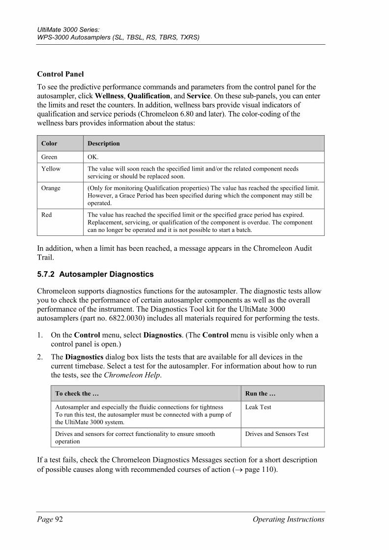
UltiMate 3000 Series: WPS-3000 Autosamplers (SL, TBSL, RS, TBRS, TXRS)
Page 92 Operating Instructions
Control Panel To see the predictive performance commands and parameters from the control panel for the autosampler, click Wellness, Qualification, and Service. On these sub-panels, you can enter the limits and reset the counters. In addition, wellness bars provide visual indicators of qualification and service periods (Chromeleon 6.80 and later). The color-coding of the wellness bars provides information about the status:
Color Description
Green OK.
Yellow The value will soon reach the specified limit and/or the related component needs servicing or should be replaced soon.
Orange (Only for monitoring Qualification properties) The value has reached the specified limit. However, a Grace Period has been specified during which the component may still be operated.
Red The value has reached the specified limit or the specified grace period has expired. Replacement, servicing, or qualification of the component is overdue. The component can no longer be operated and it is not possible to start a batch.
In addition, when a limit has been reached, a message appears in the Chromeleon Audit Trail.
5.7.2 Autosampler Diagnostics
Chromeleon supports diagnostics functions for the autosampler. The diagnostic tests allow you to check the performance of certain autosampler components as well as the overall performance of the instrument. The Diagnostics Tool kit for the UltiMate 3000 autosamplers (part no. 6822.0030) includes all materials required for performing the tests.
1. On the Control menu, select Diagnostics. (The Control menu is visible only when a control panel is open.)
2. The Diagnostics dialog box lists the tests that are available for all devices in the current timebase. Select a test for the autosampler. For information about how to run the tests, see the Chromeleon Help.
To check the … Run the …
Autosampler and especially the fluidic connections for tightness To run this test, the autosampler must be connected with a pump of the UltiMate 3000 system.
Leak Test
Drives and sensors for correct functionality to ensure smooth operation
Drives and Sensors Test
If a test fails, check the Chromeleon Diagnostics Messages section for a short description of possible causes along with recommended courses of action (→ page 110).
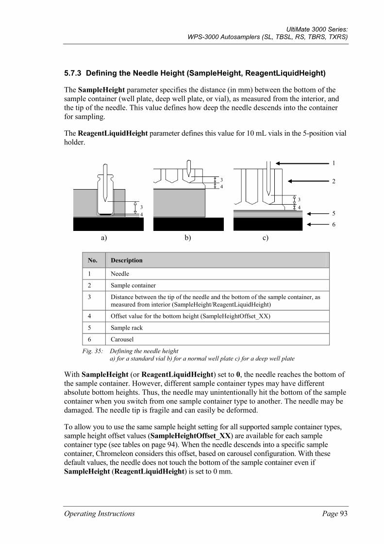
UltiMate 3000 Series: WPS-3000 Autosamplers (SL, TBSL, RS, TBRS, TXRS)
Operating Instructions Page 93
5.7.3 Defining the Needle Height (SampleHeight, ReagentLiquidHeight)
The SampleHeight parameter specifies the distance (in mm) between the bottom of the sample container (well plate, deep well plate, or vial), as measured from the interior, and the tip of the needle. This value defines how deep the needle descends into the container for sampling.
The ReagentLiquidHeight parameter defines this value for 10 mL vials in the 5-position vial holder.
a) b) c)
1
2
5
6
3 4
3 4
3 4
No. Description
1 Needle
2 Sample container
3 Distance between the tip of the needle and the bottom of the sample container, as measured from interior (SampleHeight/ReagentLiquidHeight)
4 Offset value for the bottom height (SampleHeightOffset_XX)
5 Sample rack
6 Carousel
Fig. 35: Defining the needle height a) for a standard vial b) for a normal well plate c) for a deep well plate
With SampleHeight (or ReagentLiquidHeight) set to 0, the needle reaches the bottom of the sample container. However, different sample container types may have different absolute bottom heights. Thus, the needle may unintentionally hit the bottom of the sample container when you switch from one sample container type to another. The needle may be damaged. The needle tip is fragile and can easily be deformed.
To allow you to use the same sample height setting for all supported sample container types, sample height offset values (SampleHeightOffset_XX) are available for each sample container type (see tables on page 94). When the needle descends into a specific sample container, Chromeleon considers this offset, based on carousel configuration. With these default values, the needle does not touch the bottom of the sample container even if SampleHeight (ReagentLiquidHeight) is set to 0 mm.
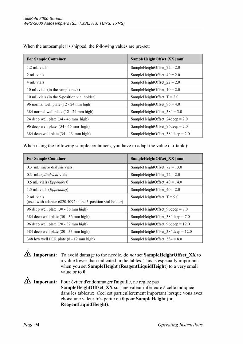
UltiMate 3000 Series: WPS-3000 Autosamplers (SL, TBSL, RS, TBRS, TXRS)
Page 94 Operating Instructions
When the autosampler is shipped, the following values are pre-set:
For Sample Container SampleHeightOffset_XX [mm]
1.2 mL vials SampleHeightOffset_72 = 2.0
2 mL vials SampleHeightOffset_40 = 2.0
4 mL vials SampleHeightOffset_22 = 2.0
10 mL vials (in the sample rack) SampleHeightOffset_10 = 2.0
10 mL vials (in the 5-position vial holder) SampleHeightOffset_T = 2.0
96 normal well plate (12 - 24 mm high) SampleHeightOffset_96 = 4.0
384 normal well plate (12 - 24 mm high) SampleHeightOffset_384 = 3.0
24 deep well plate (34 - 46 mm high) SampleHeightOffset_24deep = 2.0
96 deep well plate (34 - 46 mm high) SampleHeightOffset_96deep = 2.0
384 deep well plate (34 - 46 mm high) SampleHeightOffset_384deep = 2.0
When using the following sample containers, you have to adapt the value (→ table):
For Sample Container SampleHeightOffset_XX [mm]
0.3 mL micro dialysis vials SampleHeightOffset_72 = 13.0
0.3 mL cylindrical vials SampleHeightOffset_72 = 2.0
0.5 mL vials (Eppendorf) SampleHeightOffset_40 = 14.0
1.5 mL vials (Eppendorf) SampleHeightOffset_40 = 2.0
2 mL vials (used with adapter 6820.4092 in the 5-position vial holder)
SampleHeightOffset_T = 9.0
96 deep well plate (30 - 36 mm high) SampleHeightOffset_96deep = 7.0
384 deep well plate (30 - 36 mm high) SampleHeightOffset_384deep = 7.0
96 deep well plate (20 - 32 mm high) SampleHeightOffset_96deep = 12.0
384 deep well plate (20 - 33 mm high) SampleHeightOffset_384deep = 12.0
348 low well PCR plate (8 - 12 mm high) SampleHeightOffset_384 = 8.0
Important: To avoid damage to the needle, do not set SampleHeightOffset_XX to a value lower than indicated in the tables. This is especially important when you set SampleHeight (ReagentLiquidHeight) to a very small value or to 0.
Important: Pour éviter d'endommager l'aiguille, ne réglez pas SampleHeightOffset_XX sur une valeur inférieure à celle indiquée dans les tableaux. Ceci est particulièrement important lorsque vous avez choisi une valeur très petite ou 0 pour SampleHeight (ou ReagentLiquidHeight).
UltiMate 3000 Series: WPS-3000 Autosamplers (SL, TBSL, RS, TBRS, TXRS)
Operating Instructions Page 95
Tip: If you want to sample only once from a container, select the SampleHeight value in such a way that the needle is lowered into the sample container only as deep as required; thus, further reducing sample carry-over.
5.7.4 Moving the Tray before Drawing the Sample (Tray Shake)
To allow rehomogenization of the sample, especially after longer idle times, Chromeleon supports tray shake. To mix the analyte thoroughly before the sample is drawn, the tray is moved rapidly one or more times. Tray shake avoids changes in the peak area due to local changes in the concentration of the analyte in the sample container (for example, caused by condensation in the headspace).
The function is disabled by default (AutoTrayShakeTimes = 0). Enter a value to specify how often the tray is shaken before the sample is drawn.
5.7.5 Venting the Vial
To enhance the reproducibility, set the PunctureOffset parameter.
The carousel moves by the specified value while the needle is in the septum, thus enlarging the hole in the septum and equalizing the pressure. For vials with unslitted septa and with large injection volumes, this is especially important.
5.7.6 Operational Qualification and Performance Qualification
To check and document the performance of the HPLC system, perform Operational Qualification and Performance Qualification, All materials required for performing qualification and detailed instructions are available on request.
5.7.7 Automatic Tray Test
The automatic tray test checks whether the sample container that is installed in the segment from which the next injection shall be performed matches the configuration settings. If it does not, the needle may be damaged. The test is performed once per segment whenever the first injection (after manual interference) is performed from the segment.
The function is enabled by default. If you do not want to use this function, set EnableTrayTest to Disabled. If the adapter (part no. 6820.2402) is installed on the vial pusher, you have to disable the automatic tray test.
UltiMate 3000 Series: WPS-3000 Autosamplers (SL, TBSL, RS, TBRS, TXRS)
Page 96 Operating Instructions
5.7.8 Automatic Sample Container Detection
The vial pusher (→ Fig. 3, page 23) is fitted with a sensor for automatic detection of vials, well plates, and deep well plates.
The sensor checks whether the vial pusher descends onto a vial or well plate. If no sample container is present at the specified position, a message appears on the autosampler display and in the Chromeleon Audit Trail.
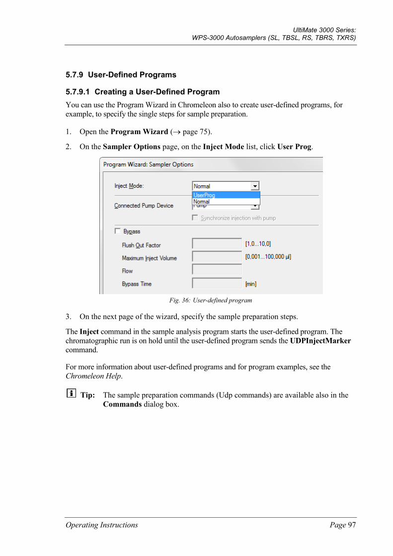
UltiMate 3000 Series: WPS-3000 Autosamplers (SL, TBSL, RS, TBRS, TXRS)
Operating Instructions Page 97
5.7.9 User-Defined Programs
5.7.9.1 Creating a User-Defined Program You can use the Program Wizard in Chromeleon also to create user-defined programs, for example, to specify the single steps for sample preparation.
1. Open the Program Wizard (→ page 75).
2. On the Sampler Options page, on the Inject Mode list, click User Prog.
Fig. 36: User-defined program
3. On the next page of the wizard, specify the sample preparation steps.
The Inject command in the sample analysis program starts the user-defined program. The chromatographic run is on hold until the user-defined program sends the UDPInjectMarker command.
For more information about user-defined programs and for program examples, see the Chromeleon Help.
Tip: The sample preparation commands (Udp commands) are available also in the Commands dialog box.
UltiMate 3000 Series: WPS-3000 Autosamplers (SL, TBSL, RS, TBRS, TXRS)
Page 98 Operating Instructions
5.7.9.2 Specifying Relative Sample Positions In user-defined programs, you can enter sample positions relative to the position of another sample. For example, you can specify a relative sample position for the vial that you want to use for sample preparation (PrepVial).
The relative position can be in a different row of the sample rack, in a different segment of the carousel, or a certain number of vials away from the current vial.
For information about how to enter relative sample positions in a program, see the Chromeleon Help.

UltiMate 3000 Series: WPS-3000 Autosamplers (SL, TBSL, RS, TBRS, TXRS)
Operating Instructions Page 99
5.8 Shutting Down the Autosampler
Observe the following precautions before interrupting the operation or before shipping the autosampler:
• Rinse out any solvents if necessary. If a buffer is used as a part of the mobile phase, flush the system with several volumes of methanol/water (50:50) before it is shut down. This prevents salt buildup inside the unit.
• If you interrupt operation for more than one week, fill the autosampler with methanol or a similar alcohol, such as 2-propanol or ethanol. If the solvents in the autosampler are not miscible with water, use an appropriate intermediate solvent.
• To move or ship the autosampler, you have to
♦ Flush the drainage. Turn on the membrane pump for a short time, by performing the PurgePumpOn command in Chromeleon.
♦ Remove the movable parts of the carousel (sample racks, vials, well plates). If installed, remove the wash liquid reservoir.
♦ Secure the needle arm and carousel cover with the foam insert (→ Packing Instructions).
Important: This is a must! To avoid damage to the needle and wash port, move the needle and needle arm into the correct position (needle arm on the right and needle out of the needle seat and wash port). Either press the Standby button on the front of the autosampler or perform the Standby command in Chromeleon. Then, turn off the autosampler and secure the needle arm.
Important: C'est a doit! Afin d'éviter tout dommage à l'aiguille et au puits de rinçage, prenez soin de parquer l'aiguille en position haute avant d'installer le bloc de mousse, en utilisant le bouton Stand-by du panneau de commande du passeur ou le command Standby dans Chromeleon.
• Ship the autosampler only in the original shipping container. Observe the packing instructions.
If the original shipping container is not available, you can order appropriate shipping containers and packing material from the Thermo Fisher Scientific sales organization for Dionex HPLC Products. The packing instructions are included in the "Installation and Qualification Documents for Chromatography Instruments" binder; they are available also on request.
Shipping the unit in any other packaging automatically voids the warranty.
From Chromeleon, you can set the autosampler and HPLC system into the standby mode or automate system shutdown (→ page 100).
UltiMate 3000 Series: WPS-3000 Autosamplers (SL, TBSL, RS, TBRS, TXRS)
Page 100 Operating Instructions
Standby Program A standby program sets the HPLC system into standby mode. The main program steps are:
• At the end of the program, the program automatically reduces the flow.
• The program reduces temperature of all temperature-controlled modules in the system.
From the standby mode, you can reactivate the application very quickly.
Shutdown Program A shutdown program automates shutdown of the HPLC system. The main program steps are:
• At the end of the program, the program automatically reduces the flow.
• The program turns off certain system components and functions (for example, detector lamps, temperature control).
To create a standby or shutdown program Select one of the following alternatives:
• Select and perform the operating commands and parameters from the Commands dialog box.
• Create and run a program (→ page 75).
• Use the SmartShutdown Wizard to create and run the program (see further down).
To create the program with the SmartShutdown wizard 1. To open the wizard, click SmartShutdown on the Batch menu.
2. Follow the instructions as they appear on each page of the wizard. For additional information about a page, click Help.
3. After you finish the wizard, Chromeleon
♦ Creates the program and saves it in the timebase for which you create the program. ♦ Opens the Start Batch on dialog box. To run the program, select the program and click Start.
For more information about the SmartShutdown wizard, see the Chromeleon Help.
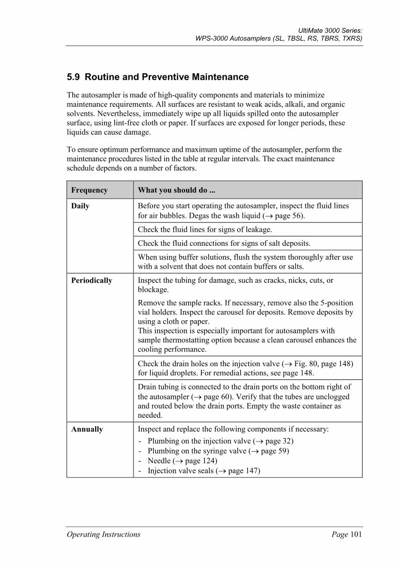
UltiMate 3000 Series: WPS-3000 Autosamplers (SL, TBSL, RS, TBRS, TXRS)
Operating Instructions Page 101
5.9 Routine and Preventive Maintenance
The autosampler is made of high-quality components and materials to minimize maintenance requirements. All surfaces are resistant to weak acids, alkali, and organic solvents. Nevertheless, immediately wipe up all liquids spilled onto the autosampler surface, using lint-free cloth or paper. If surfaces are exposed for longer periods, these liquids can cause damage.
To ensure optimum performance and maximum uptime of the autosampler, perform the maintenance procedures listed in the table at regular intervals. The exact maintenance schedule depends on a number of factors.
Frequency What you should do ...
Daily Before you start operating the autosampler, inspect the fluid lines for air bubbles. Degas the wash liquid (→ page 56).
Check the fluid lines for signs of leakage.
Check the fluid connections for signs of salt deposits.
When using buffer solutions, flush the system thoroughly after use with a solvent that does not contain buffers or salts.
Periodically Inspect the tubing for damage, such as cracks, nicks, cuts, or blockage.
Remove the sample racks. If necessary, remove also the 5-position vial holders. Inspect the carousel for deposits. Remove deposits by using a cloth or paper. This inspection is especially important for autosamplers with sample thermostatting option because a clean carousel enhances the cooling performance.
Check the drain holes on the injection valve (→ Fig. 80, page 148) for liquid droplets. For remedial actions, see page 148.
Drain tubing is connected to the drain ports on the bottom right of the autosampler (→ page 60). Verify that the tubes are unclogged and routed below the drain ports. Empty the waste container as needed.
Annually Inspect and replace the following components if necessary: - Plumbing on the injection valve (→ page 32) - Plumbing on the syringe valve (→ page 59) - Needle (→ page 124) - Injection valve seals (→ page 147)
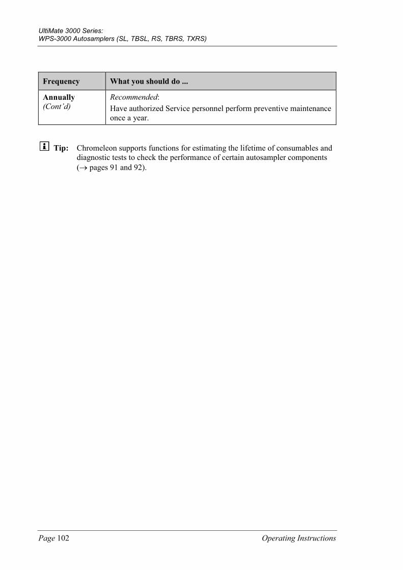
UltiMate 3000 Series: WPS-3000 Autosamplers (SL, TBSL, RS, TBRS, TXRS)
Page 102 Operating Instructions
Frequency What you should do ...
Annually (Cont’d)
Recommended: Have authorized Service personnel perform preventive maintenance once a year.
Tip: Chromeleon supports functions for estimating the lifetime of consumables and diagnostic tests to check the performance of certain autosampler components (→ pages 91 and 92).
UltiMate 3000 Series: WPS-3000 Autosamplers (SL, TBSL, RS, TBRS, TXRS)
Operating Instructions Page 103
6 Troubleshooting
6.1 Overview
The following features help you to identify and eliminate the source for problems that may occur during the operation of the autosampler or an UltiMate 3000 system:
Status LEDs
The status LEDs (light emitting diodes) on the front panel provide a quick visual check of the operational status of the autosampler. They indicate whether the autosampler is turned on, connected in Chromeleon, and operating properly (→ page 24).
Messages If a fault or error is detected during the operation of the autosampler, a message appears on the autosampler display. Check the Messages on the Autosampler Display section for recommended courses of action (→ page 104). If the autosampler is operated from Chromeleon, a message is displayed also in the Chromeleon Audit Trail.
Tip: For information about operating problems that might occur during the operation of an UltiMate 3000 system, see Operating Problems (→ page 112).
Diagnostics Tests If the autosampler is operated from Chromeleon, diagnostic tests are available to check the performance of certain autosampler components (→ page 92). If a test fails, check the Chromeleon Diagnostics Messages section for a short description of possible causes along with recommended courses of action (→ page 110).
If you are unable to eliminate a problem following the instructions given here, contact Thermo Fisher Scientific Service for Dionex HPLC Products.
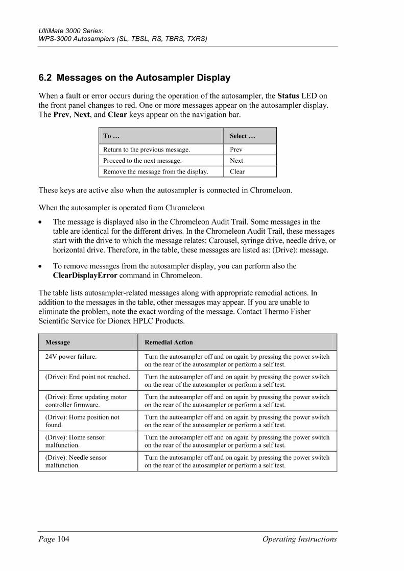
UltiMate 3000 Series: WPS-3000 Autosamplers (SL, TBSL, RS, TBRS, TXRS)
Page 104 Operating Instructions
6.2 Messages on the Autosampler Display
When a fault or error occurs during the operation of the autosampler, the Status LED on the front panel changes to red. One or more messages appear on the autosampler display. The Prev, Next, and Clear keys appear on the navigation bar.
To … Select …
Return to the previous message. Prev Proceed to the next message. Next Remove the message from the display. Clear
These keys are active also when the autosampler is connected in Chromeleon.
When the autosampler is operated from Chromeleon
• The message is displayed also in the Chromeleon Audit Trail. Some messages in the table are identical for the different drives. In the Chromeleon Audit Trail, these messages start with the drive to which the message relates: Carousel, syringe drive, needle drive, or horizontal drive. Therefore, in the table, these messages are listed as: (Drive): message.
• To remove messages from the autosampler display, you can perform also the ClearDisplayError command in Chromeleon.
The table lists autosampler-related messages along with appropriate remedial actions. In addition to the messages in the table, other messages may appear. If you are unable to eliminate the problem, note the exact wording of the message. Contact Thermo Fisher Scientific Service for Dionex HPLC Products.
Message Remedial Action
24V power failure. Turn the autosampler off and on again by pressing the power switch on the rear of the autosampler or perform a self test.
(Drive): End point not reached. Turn the autosampler off and on again by pressing the power switch on the rear of the autosampler or perform a self test.
(Drive): Error updating motor controller firmware.
Turn the autosampler off and on again by pressing the power switch on the rear of the autosampler or perform a self test.
(Drive): Home position not found.
Turn the autosampler off and on again by pressing the power switch on the rear of the autosampler or perform a self test.
(Drive): Home sensor malfunction.
Turn the autosampler off and on again by pressing the power switch on the rear of the autosampler or perform a self test.
(Drive): Needle sensor malfunction.
Turn the autosampler off and on again by pressing the power switch on the rear of the autosampler or perform a self test.
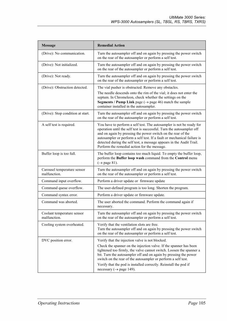
UltiMate 3000 Series: WPS-3000 Autosamplers (SL, TBSL, RS, TBRS, TXRS)
Operating Instructions Page 105
Message Remedial Action
(Drive): No communication. Turn the autosampler off and on again by pressing the power switch on the rear of the autosampler or perform a self test.
(Drive): Not initialized. Turn the autosampler off and on again by pressing the power switch on the rear of the autosampler or perform a self test.
(Drive): Not ready. Turn the autosampler off and on again by pressing the power switch on the rear of the autosampler or perform a self test.
(Drive): Obstruction detected. The vial pusher is obstructed. Remove any obstacles. The needle descends onto the rim of the vial; it does not enter the septum. In Chromeleon, check whether the settings on the Segments / Pump Link page (→ page 46) match the sample container installed in the autosampler.
(Drive): Stop condition at start. Turn the autosampler off and on again by pressing the power switch on the rear of the autosampler or perform a self test.
A self test is required. You have to perform a self test. The autosampler is not be ready for operation until the self test is successful. Turn the autosampler off and on again by pressing the power switch on the rear of the autosampler or perform a self test. If a fault or mechanical failure is detected during the self test, a message appears in the Audit Trail. Perform the remedial action for the message.
Buffer loop is too full. The buffer loop contains too much liquid. To empty the buffer loop, perform the Buffer loop wash command from the Control menu (→ page 81).
Carousel temperature sensor malfunction.
Turn the autosampler off and on again by pressing the power switch on the rear of the autosampler or perform a self test.
Command input overflow. Perform a driver update or firmware update
Command queue overflow. The user-defined program is too long. Shorten the program.
Command syntax error. Perform a driver update or firmware update.
Command was aborted. The user aborted the command. Perform the command again if necessary.
Coolant temperature sensor malfunction.
Turn the autosampler off and on again by pressing the power switch on the rear of the autosampler or perform a self test.
Cooling system overheated. Verify that the ventilation slots are free. Turn the autosampler off and on again by pressing the power switch on the rear of the autosampler or perform a self test.
DVC position error. Verify that the injection valve is not blocked. Check the spanner on the injection valve. If the spanner has been tightened too firmly, the valve cannot switch. Loosen the spanner a bit. Turn the autosampler off and on again by pressing the power switch on the rear of the autosampler or perform a self test. Verify that the pod is installed correctly. Reinstall the pod if necessary (→ page 149).
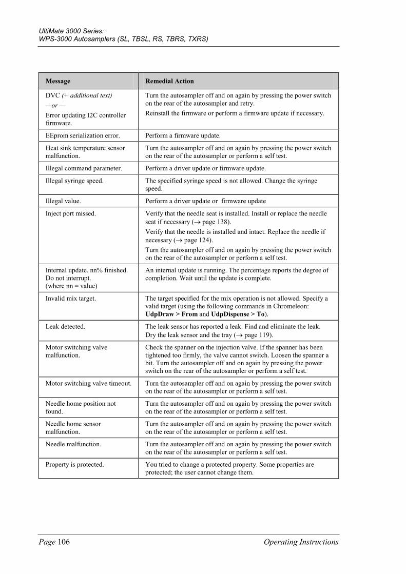
UltiMate 3000 Series: WPS-3000 Autosamplers (SL, TBSL, RS, TBRS, TXRS)
Page 106 Operating Instructions
Message Remedial Action
DVC (+ additional text) —or — Error updating I2C controller firmware.
Turn the autosampler off and on again by pressing the power switch on the rear of the autosampler and retry. Reinstall the firmware or perform a firmware update if necessary.
EEprom serialization error. Perform a firmware update.
Heat sink temperature sensor malfunction.
Turn the autosampler off and on again by pressing the power switch on the rear of the autosampler or perform a self test.
Illegal command parameter. Perform a driver update or firmware update.
Illegal syringe speed. The specified syringe speed is not allowed. Change the syringe speed.
Illegal value. Perform a driver update or firmware update
Inject port missed. Verify that the needle seat is installed. Install or replace the needle seat if necessary (→ page 138). Verify that the needle is installed and intact. Replace the needle if necessary (→ page 124). Turn the autosampler off and on again by pressing the power switch on the rear of the autosampler or perform a self test.
Internal update. nn% finished. Do not interrupt. (where nn = value)
An internal update is running. The percentage reports the degree of completion. Wait until the update is complete.
Invalid mix target. The target specified for the mix operation is not allowed. Specify a valid target (using the following commands in Chromeleon: UdpDraw > From and UdpDispense > To).
Leak detected. The leak sensor has reported a leak. Find and eliminate the leak. Dry the leak sensor and the tray (→ page 119).
Motor switching valve malfunction.
Check the spanner on the injection valve. If the spanner has been tightened too firmly, the valve cannot switch. Loosen the spanner a bit. Turn the autosampler off and on again by pressing the power switch on the rear of the autosampler or perform a self test.
Motor switching valve timeout. Turn the autosampler off and on again by pressing the power switch on the rear of the autosampler or perform a self test.
Needle home position not found.
Turn the autosampler off and on again by pressing the power switch on the rear of the autosampler or perform a self test.
Needle home sensor malfunction.
Turn the autosampler off and on again by pressing the power switch on the rear of the autosampler or perform a self test.
Needle malfunction. Turn the autosampler off and on again by pressing the power switch on the rear of the autosampler or perform a self test.
Property is protected. You tried to change a protected property. Some properties are protected; the user cannot change them.
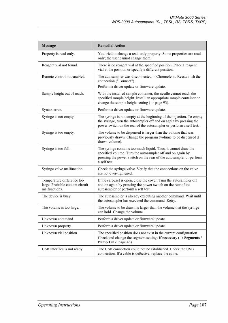
UltiMate 3000 Series: WPS-3000 Autosamplers (SL, TBSL, RS, TBRS, TXRS)
Operating Instructions Page 107
Message Remedial Action
Property is read only. You tried to change a read-only property. Some properties are read-only; the user cannot change them.
Reagent vial not found. There is no reagent vial at the specified position. Place a reagent vial at the position or specify a different position.
Remote control not enabled. The autosampler was disconnected in Chromeleon. Reestablish the connection ("Connect"). Perform a driver update or firmware update.
Sample height out of reach. With the installed sample container, the needle cannot reach the specified sample height. Install an appropriate sample container or change the sample height setting (→ page 93).
Syntax error. Perform a driver update or firmware update.
Syringe is not empty. The syringe is not empty at the beginning of the injection. To empty the syringe, turn the autosampler off and on again by pressing the power switch on the rear of the autosampler or perform a self test.
Syringe is too empty. The volume to be dispensed is larger than the volume that was previously drawn. Change the program (volume to be dispensed ≤ drawn volume).
Syringe is too full. The syringe contains too much liquid. Thus, it cannot draw the specified volume. Turn the autosampler off and on again by pressing the power switch on the rear of the autosampler or perform a self test.
Syringe valve malfunction. Check the syringe valve. Verify that the connections on the valve are not over-tightened.
Temperature difference too large. Probable coolant circuit malfunctions.
If the carousel is open, close the cover. Turn the autosampler off and on again by pressing the power switch on the rear of the autosampler or perform a self test.
The device is busy. The autosampler is already executing another command. Wait until the autosampler has executed the command .Retry.
The volume is too large. The volume to be drawn is larger than the volume that the syringe can hold. Change the volume.
Unknown command. Perform a driver update or firmware update.
Unknown property. Perform a driver update or firmware update.
Unknown vial position. The specified position does not exist in the current configuration. Check and change the segment settings if necessary (→ Segments / Pump Link, page 46).
USB interface is not ready. The USB connection could not be established. Check the USB connection. If a cable is defective, replace the cable.

UltiMate 3000 Series: WPS-3000 Autosamplers (SL, TBSL, RS, TBRS, TXRS)
Page 108 Operating Instructions
Message Remedial Action
Vial not found. No sample container is present at the specified position. Place a sample container at the specified position or specify a different position. The message appears also if your sample containers do not meet the minimum height requirements (→ page 29). Use the sample containers listed on page 29. The segment type is wrong. Check and correct the segment settings if necessary (→ Segments / Pump Link, page 46).
Vial pusher malfunction. Turn the autosampler off and on again by pressing the power switch on the rear of the autosampler or perform a self test.
Vial pusher obstructed. The vial pusher is obstructed. Remove any obstacles.
Wash port missed. Turn the autosampler off and on again by pressing the power switch on the rear of the autosampler or perform a self test.
Wrong tray type detected. Automatic tray detection reports that the sample containers specified on the Segments / Pump Link page in Chromeleon do not match the sample containers installed. Check and correct the segment settings if necessary (→ Segments / Pump Link, page 46). This message appears also if your sample containers do not meet the minimum height requirements (→ page 29). Use the sample containers listed on page 29.
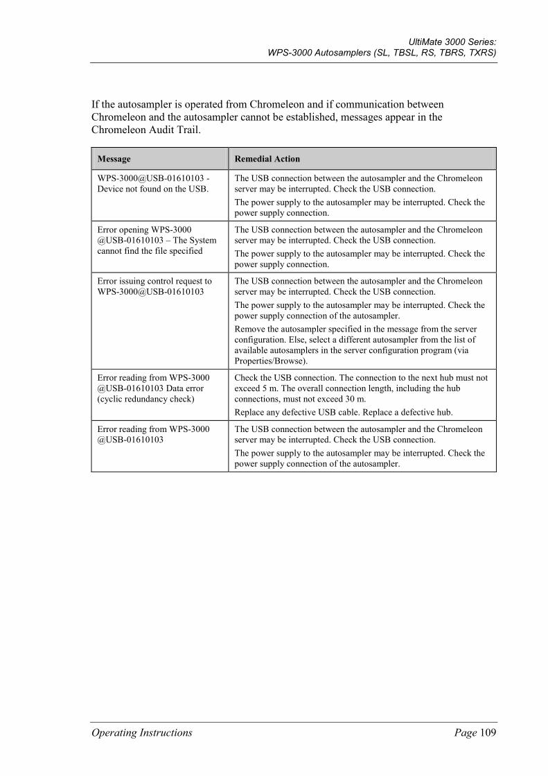
UltiMate 3000 Series: WPS-3000 Autosamplers (SL, TBSL, RS, TBRS, TXRS)
Operating Instructions Page 109
If the autosampler is operated from Chromeleon and if communication between Chromeleon and the autosampler cannot be established, messages appear in the Chromeleon Audit Trail.
Message Remedial Action
WPS-3000@USB-01610103 - Device not found on the USB.
The USB connection between the autosampler and the Chromeleon server may be interrupted. Check the USB connection. The power supply to the autosampler may be interrupted. Check the power supply connection.
Error opening WPS-3000 @USB-01610103 – The System cannot find the file specified
The USB connection between the autosampler and the Chromeleon server may be interrupted. Check the USB connection. The power supply to the autosampler may be interrupted. Check the power supply connection.
Error issuing control request to WPS-3000@USB-01610103
The USB connection between the autosampler and the Chromeleon server may be interrupted. Check the USB connection. The power supply to the autosampler may be interrupted. Check the power supply connection of the autosampler. Remove the autosampler specified in the message from the server configuration. Else, select a different autosampler from the list of available autosamplers in the server configuration program (via Properties/Browse).
Error reading from WPS-3000 @USB-01610103 Data error (cyclic redundancy check)
Check the USB connection. The connection to the next hub must not exceed 5 m. The overall connection length, including the hub connections, must not exceed 30 m. Replace any defective USB cable. Replace a defective hub.
Error reading from WPS-3000 @USB-01610103
The USB connection between the autosampler and the Chromeleon server may be interrupted. Check the USB connection. The power supply to the autosampler may be interrupted. Check the power supply connection of the autosampler.
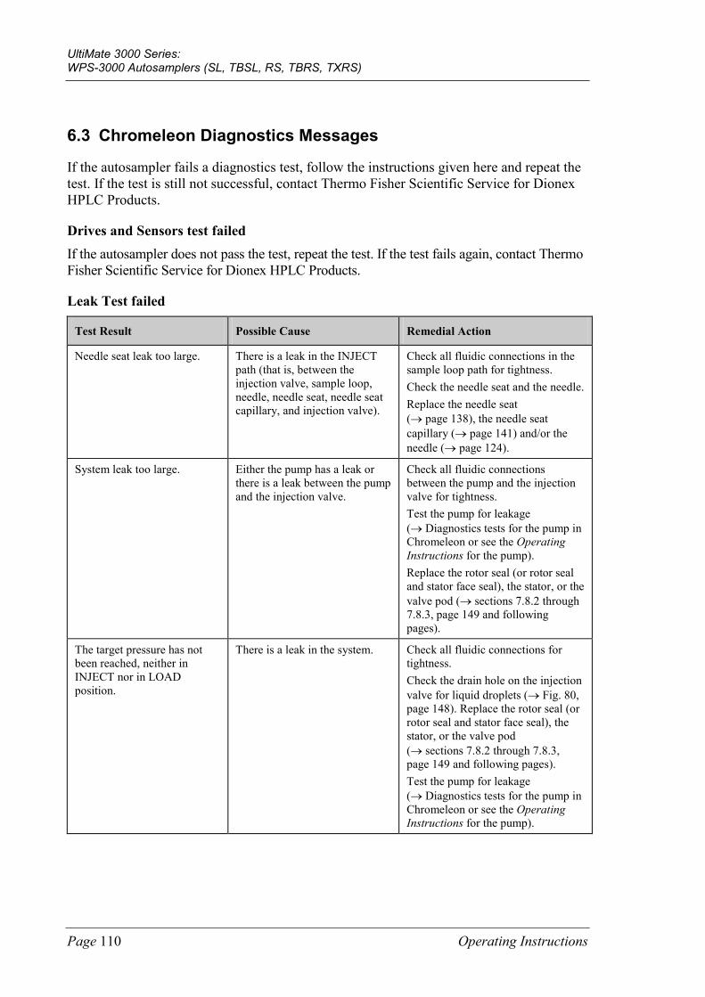
UltiMate 3000 Series: WPS-3000 Autosamplers (SL, TBSL, RS, TBRS, TXRS)
Page 110 Operating Instructions
6.3 Chromeleon Diagnostics Messages
If the autosampler fails a diagnostics test, follow the instructions given here and repeat the test. If the test is still not successful, contact Thermo Fisher Scientific Service for Dionex HPLC Products.
Drives and Sensors test failed If the autosampler does not pass the test, repeat the test. If the test fails again, contact Thermo Fisher Scientific Service for Dionex HPLC Products.
Leak Test failed
Test Result Possible Cause Remedial Action
Needle seat leak too large. There is a leak in the INJECT path (that is, between the injection valve, sample loop, needle, needle seat, needle seat capillary, and injection valve).
Check all fluidic connections in the sample loop path for tightness. Check the needle seat and the needle. Replace the needle seat (→ page 138), the needle seat capillary (→ page 141) and/or the needle (→ page 124).
System leak too large. Either the pump has a leak or there is a leak between the pump and the injection valve.
Check all fluidic connections between the pump and the injection valve for tightness. Test the pump for leakage (→ Diagnostics tests for the pump in Chromeleon or see the Operating Instructions for the pump). Replace the rotor seal (or rotor seal and stator face seal), the stator, or the valve pod (→ sections 7.8.2 through 7.8.3, page 149 and following pages).
The target pressure has not been reached, neither in INJECT nor in LOAD position.
There is a leak in the system. Check all fluidic connections for tightness. Check the drain hole on the injection valve for liquid droplets (→ Fig. 80, page 148). Replace the rotor seal (or rotor seal and stator face seal), the stator, or the valve pod (→ sections 7.8.2 through 7.8.3, page 149 and following pages). Test the pump for leakage (→ Diagnostics tests for the pump in Chromeleon or see the Operating Instructions for the pump).
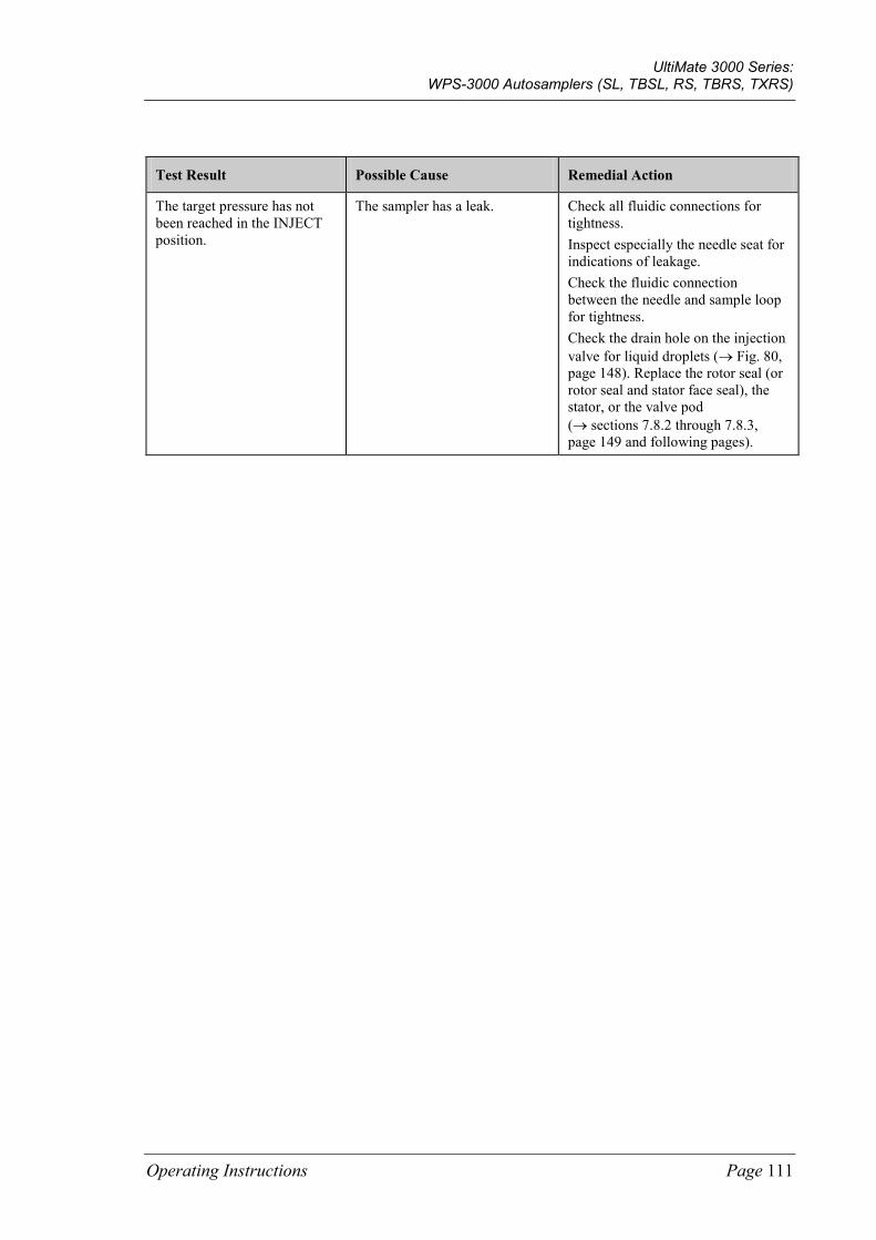
UltiMate 3000 Series: WPS-3000 Autosamplers (SL, TBSL, RS, TBRS, TXRS)
Operating Instructions Page 111
Test Result Possible Cause Remedial Action
The target pressure has not been reached in the INJECT position.
The sampler has a leak. Check all fluidic connections for tightness. Inspect especially the needle seat for indications of leakage. Check the fluidic connection between the needle and sample loop for tightness. Check the drain hole on the injection valve for liquid droplets (→ Fig. 80, page 148). Replace the rotor seal (or rotor seal and stator face seal), the stator, or the valve pod (→ sections 7.8.2 through 7.8.3, page 149 and following pages).
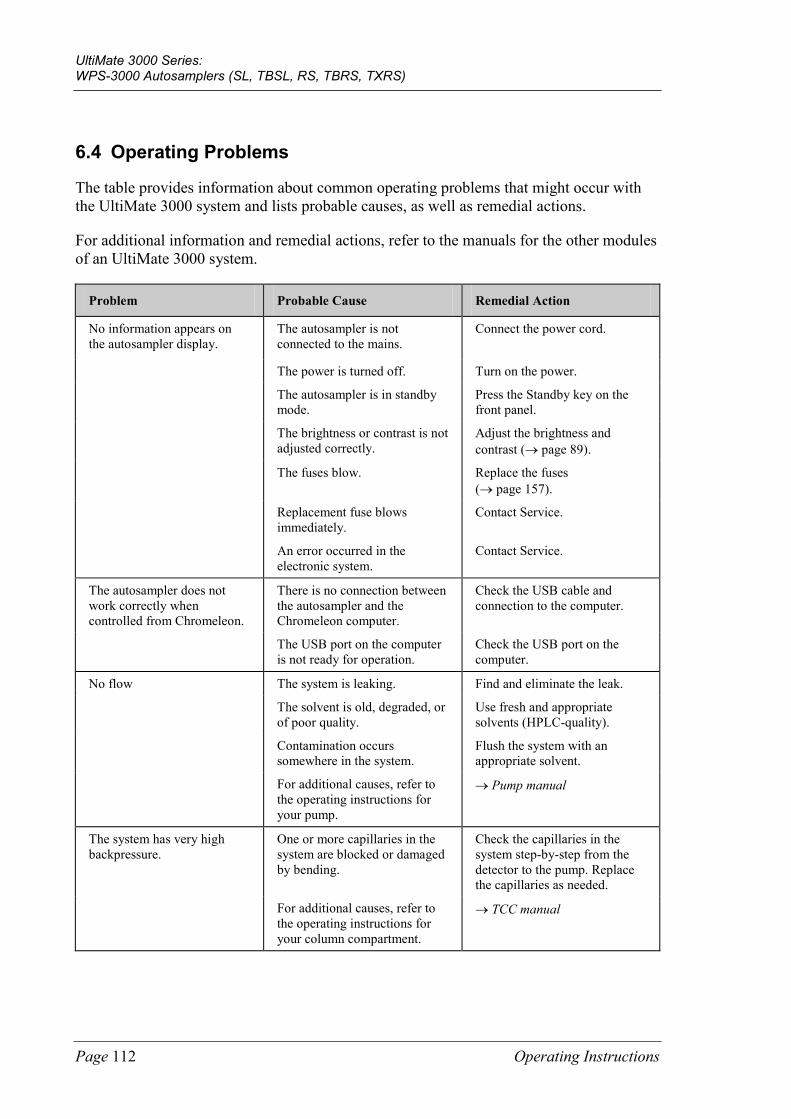
UltiMate 3000 Series: WPS-3000 Autosamplers (SL, TBSL, RS, TBRS, TXRS)
Page 112 Operating Instructions
6.4 Operating Problems
The table provides information about common operating problems that might occur with the UltiMate 3000 system and lists probable causes, as well as remedial actions.
For additional information and remedial actions, refer to the manuals for the other modules of an UltiMate 3000 system.
Problem Probable Cause Remedial Action
No information appears on the autosampler display.
The autosampler is not connected to the mains.
Connect the power cord.
The power is turned off. Turn on the power.
The autosampler is in standby mode.
Press the Standby key on the front panel.
The brightness or contrast is not adjusted correctly.
Adjust the brightness and contrast (→ page 89).
The fuses blow. Replace the fuses (→ page 157).
Replacement fuse blows immediately.
Contact Service.
An error occurred in the electronic system.
Contact Service.
The autosampler does not work correctly when controlled from Chromeleon.
There is no connection between the autosampler and the Chromeleon computer.
Check the USB cable and connection to the computer.
The USB port on the computer is not ready for operation.
Check the USB port on the computer.
No flow The system is leaking. Find and eliminate the leak.
The solvent is old, degraded, or of poor quality.
Use fresh and appropriate solvents (HPLC-quality).
Contamination occurs somewhere in the system.
Flush the system with an appropriate solvent.
For additional causes, refer to the operating instructions for your pump.
→ Pump manual
The system has very high backpressure.
One or more capillaries in the system are blocked or damaged by bending.
Check the capillaries in the system step-by-step from the detector to the pump. Replace the capillaries as needed.
For additional causes, refer to the operating instructions for your column compartment.
→ TCC manual
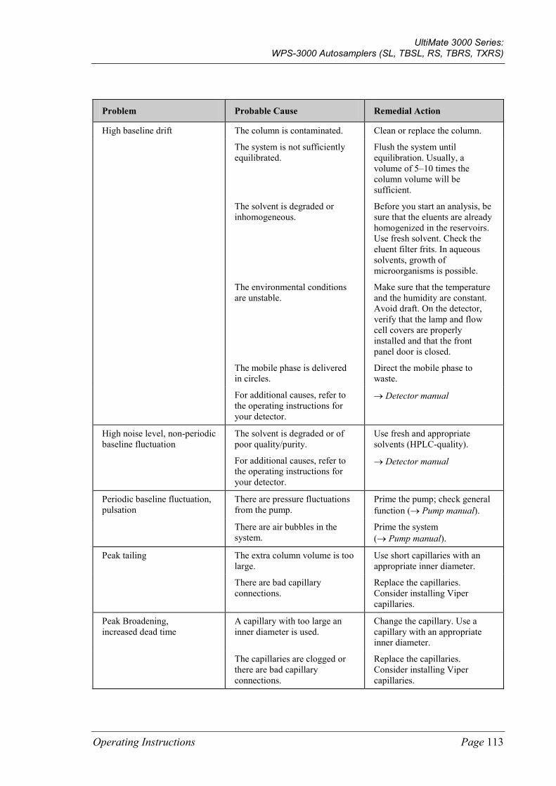
UltiMate 3000 Series: WPS-3000 Autosamplers (SL, TBSL, RS, TBRS, TXRS)
Operating Instructions Page 113
Problem Probable Cause Remedial Action
High baseline drift The column is contaminated. Clean or replace the column.
The system is not sufficiently equilibrated.
Flush the system until equilibration. Usually, a volume of 5–10 times the column volume will be sufficient.
The solvent is degraded or inhomogeneous.
Before you start an analysis, be sure that the eluents are already homogenized in the reservoirs. Use fresh solvent. Check the eluent filter frits. In aqueous solvents, growth of microorganisms is possible.
The environmental conditions are unstable.
Make sure that the temperature and the humidity are constant. Avoid draft. On the detector, verify that the lamp and flow cell covers are properly installed and that the front panel door is closed.
The mobile phase is delivered in circles.
Direct the mobile phase to waste.
For additional causes, refer to the operating instructions for your detector.
→ Detector manual
High noise level, non-periodic baseline fluctuation
The solvent is degraded or of poor quality/purity.
Use fresh and appropriate solvents (HPLC-quality).
For additional causes, refer to the operating instructions for your detector.
→ Detector manual
Periodic baseline fluctuation, pulsation
There are pressure fluctuations from the pump.
Prime the pump; check general function (→ Pump manual).
There are air bubbles in the system.
Prime the system (→ Pump manual).
Peak tailing The extra column volume is too large.
Use short capillaries with an appropriate inner diameter.
There are bad capillary connections.
Replace the capillaries. Consider installing Viper capillaries.
Peak Broadening, increased dead time
A capillary with too large an inner diameter is used.
Change the capillary. Use a capillary with an appropriate inner diameter.
The capillaries are clogged or there are bad capillary connections.
Replace the capillaries. Consider installing Viper capillaries.
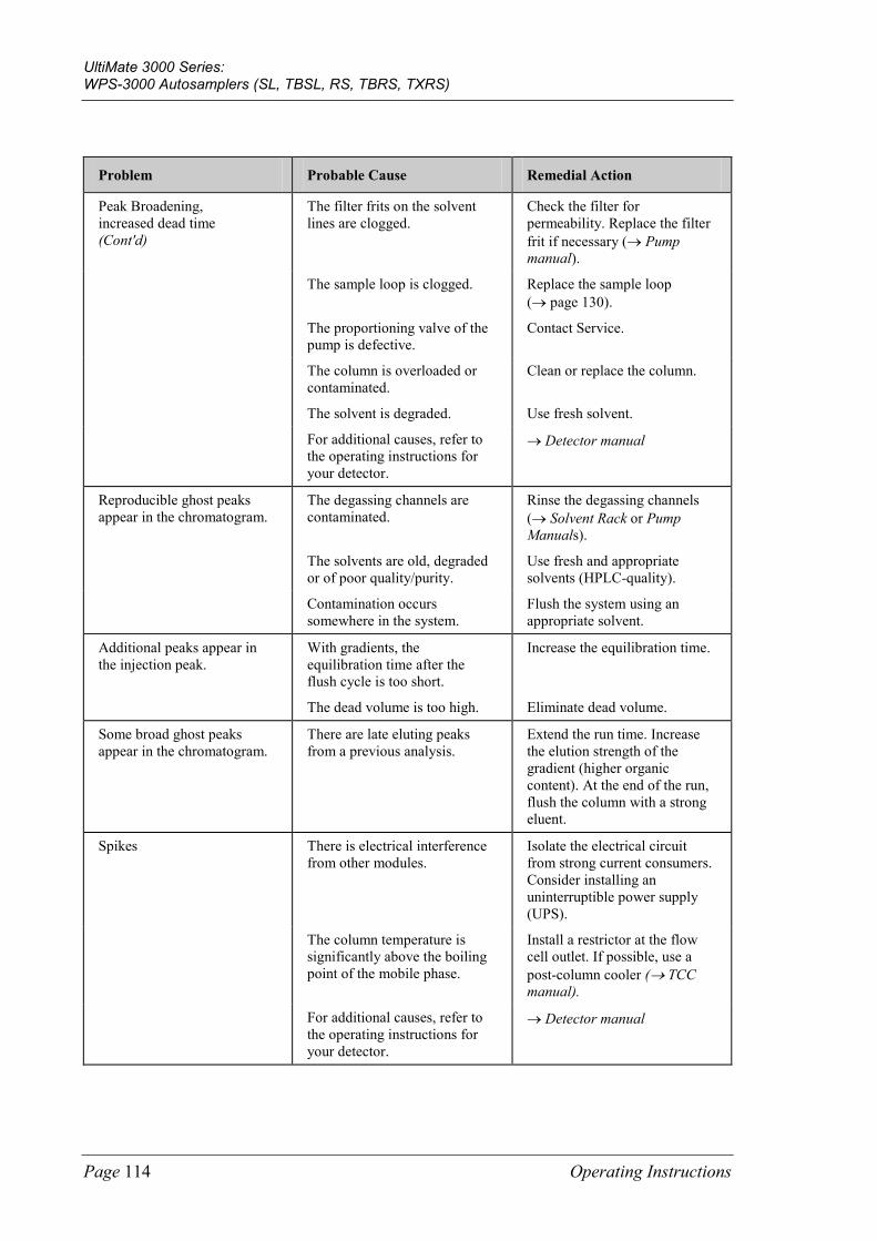
UltiMate 3000 Series: WPS-3000 Autosamplers (SL, TBSL, RS, TBRS, TXRS)
Page 114 Operating Instructions
Problem Probable Cause Remedial Action
Peak Broadening, increased dead time (Cont'd)
The filter frits on the solvent lines are clogged.
Check the filter for permeability. Replace the filter frit if necessary (→ Pump manual).
The sample loop is clogged. Replace the sample loop (→ page 130).
The proportioning valve of the pump is defective.
Contact Service.
The column is overloaded or contaminated.
Clean or replace the column.
The solvent is degraded. Use fresh solvent.
For additional causes, refer to the operating instructions for your detector.
→ Detector manual
Reproducible ghost peaks appear in the chromatogram.
The degassing channels are contaminated.
Rinse the degassing channels (→ Solvent Rack or Pump Manuals).
The solvents are old, degraded or of poor quality/purity.
Use fresh and appropriate solvents (HPLC-quality).
Contamination occurs somewhere in the system.
Flush the system using an appropriate solvent.
Additional peaks appear in the injection peak.
With gradients, the equilibration time after the flush cycle is too short.
Increase the equilibration time.
The dead volume is too high. Eliminate dead volume.
Some broad ghost peaks appear in the chromatogram.
There are late eluting peaks from a previous analysis.
Extend the run time. Increase the elution strength of the gradient (higher organic content). At the end of the run, flush the column with a strong eluent.
Spikes There is electrical interference from other modules.
Isolate the electrical circuit from strong current consumers. Consider installing an uninterruptible power supply (UPS).
The column temperature is significantly above the boiling point of the mobile phase.
Install a restrictor at the flow cell outlet. If possible, use a post-column cooler (→ TCC manual).
For additional causes, refer to the operating instructions for your detector.
→ Detector manual
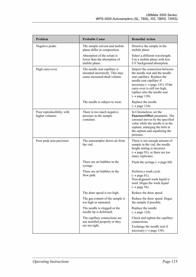
UltiMate 3000 Series: WPS-3000 Autosamplers (SL, TBSL, RS, TBRS, TXRS)
Operating Instructions Page 115
Problem Probable Cause Remedial Action
Negative peaks The sample solvent and mobile phase differ in composition.
Dissolve the sample in the mobile phase.
Absorption of the solute is lower than the absorption of mobile phase.
Select a different wavelength. Use a mobile phase with less UV background absorption.
High carry-over The needle seat capillary is mounted incorrectly. This may cause increased dead volume.
Inspect the connection between the needle seat and the needle seat capillary. Replace the needle seat capillary if necessary (→ page 141). If the carry-over is still too high, replace also the needle seat (→ page 138).
The needle is subject to wear. Replace the needle (→ page 124).
Poor reproducibility with higher volumes
There is too much negative pressure in the sample container.
In Chromeleon, set the PunctureOffset parameter. The carousel moves by the specified value while the needle is in the septum, enlarging the hole in the septum and equalizing the pressure.
Poor peak area precision The autosampler draws air from the vial.
There is not enough amount of sample in the vial, the needle height setting is incorrect (→ page 93), or there are too many replicates.
There are air bubbles in the syringe.
Flush the syringe (→ page 60).
There are air bubbles in the flow path.
Perform a wash cycle (→ page 81). Non-degassed wash liquid is used. Degas the wash liquid (→ page 56).
The draw speed is too high. Reduce the draw speed.
The gas content of the sample is too high or saturated.
Reduce the draw speed. Degas the sample if possible.
The needle is clogged or the needle tip is deformed.
Replace the needle (→ page 124).
The capillary connections are not installed properly or they are not tight.
Check and tighten the capillary connections. Exchange the needle seat if necessary (→ page 138).
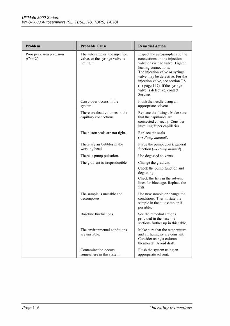
UltiMate 3000 Series: WPS-3000 Autosamplers (SL, TBSL, RS, TBRS, TXRS)
Page 116 Operating Instructions
Problem Probable Cause Remedial Action
Poor peak area precision (Cont'd)
The autosampler, the injection valve, or the syringe valve is not tight.
Inspect the autosampler and the connections on the injection valve or syringe valve. Tighten leaking connections. The injection valve or syringe valve may be defective. For the injection valve, see section 7.8 (→ page 147). If the syringe valve is defective, contact Service.
Carry-over occurs in the system.
Flush the needle using an appropriate solvent.
There are dead volumes in the capillary connections.
Replace the fittings. Make sure that the capillaries are connected correctly. Consider installing Viper capillaries.
The piston seals are not tight. Replace the seals (→ Pump manual).
There are air bubbles in the working head.
Purge the pump; check general function (→ Pump manual).
There is pump pulsation. Use degassed solvents.
The gradient is irreproducible. Change the gradient. Check the pump function and degassing. Check the frits in the solvent lines for blockage. Replace the frits.
The sample is unstable and decomposes.
Use new sample or change the conditions. Thermostate the sample in the autosampler if possible.
Baseline fluctuations See the remedial actions provided in the baseline sections further up in this table.
The environmental conditions are unstable.
Make sure that the temperature and air humidity are constant. Consider using a column thermostat. Avoid draft.
Contamination occurs somewhere in the system.
Flush the system using an appropriate solvent.
UltiMate 3000 Series: WPS-3000 Autosamplers (SL, TBSL, RS, TBRS, TXRS)
Operating Instructions Page 117
7 Service
7.1 General Notes and Safety Precautions
The following sections describe all procedures for the autosampler that the user may perform. All other maintenance and service procedures must be performed only by Thermo Fisher Scientific service personnel.
Warning: The fluid components of the device may be filled with solvents that are harmful to health. In the same way, harmful substances may be present at the wetted parts. Wear appropriate personal protective equipment. Rinse the fluid components with an appropriate solvent to remove harmful substances.
For information about the proper handling of a particular substance and for advice on specific hazards, refer to the material safety data sheet for the substance you are using. Observe the guidelines of Good Laboratory Practice (GLP).
Avertissement: Les composants fluidiques de l'instrument peuvent être remplis de solvants nocifs. De la même, des substances nocives peuvent être présents sur les pièces en contact avec le fluide. Portez l'équipement de protection personnel approprié. Rincez les composants fluidiques avec un solvant approprié afin d'éliminer les substances nocives.
Pour les informations sur la manipulation correcte des substances et des recommandations pour les situations de risque spécifiques, veuillez consulter la fiche de données de sécurité des substances que vous utilisez. Veuillez respecter des directives des Bonnes Pratiques de Laboratoire (BPL).
Before starting maintenance or service procedures, observe the following precautions:
• For all service and repair procedures, observe all precautionary statements provided in these operating instructions.
• When performing maintenance or repair work on the fluid components, you have to move the syringe and needle in the appropriate position first. To avoid damage to the syringe and instrument, do not place any objects under the syringe plunger.
• Recommended Test the autosampler for leakage after you have performed maintenance or repair work on the fluid connections. Perform the Leak Test in Chromeleon .
• Use only the original spare parts authorized for the device by Thermo Fisher Scientific.
UltiMate 3000 Series: WPS-3000 Autosamplers (SL, TBSL, RS, TBRS, TXRS)
Page 118 Operating Instructions
• Before returning any instrument for repair, contact Thermo Fisher Scientific Service for Dionex HPLC Products. An RMA (Return Material Authorization) number is required to track your instrument. Always use the original shipping container. Observe the packing instructions when shipping the autosampler. Shipping the instrument in anything other than the original packaging voids the warranty.
If the original shipping container is not available, appropriate shipping containers and packing material can be ordered from the Thermo Fisher Scientific sales organization for Dionex HPLC Products. The packing instructions are included in the "Installation and Qualification Documents for Chromatography Instruments" binder. They are available also on request.
For instructions on shutting down the autosampler, see page 99.
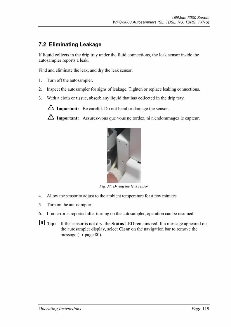
UltiMate 3000 Series: WPS-3000 Autosamplers (SL, TBSL, RS, TBRS, TXRS)
Operating Instructions Page 119
7.2 Eliminating Leakage
If liquid collects in the drip tray under the fluid connections, the leak sensor inside the autosampler reports a leak.
Find and eliminate the leak, and dry the leak sensor.
1. Turn off the autosampler.
2. Inspect the autosampler for signs of leakage. Tighten or replace leaking connections.
3. With a cloth or tissue, absorb any liquid that has collected in the drip tray.
Important: Be careful. Do not bend or damage the sensor.
Important: Assurez-vous que vous ne tordez, ni n'endommagez le capteur.
Fig. 37: Drying the leak sensor
4. Allow the sensor to adjust to the ambient temperature for a few minutes.
5. Turn on the autosampler.
6. If no error is reported after turning on the autosampler, operation can be resumed.
Tip: If the sensor is not dry, the Status LED remains red. If a message appeared on the autosampler display, select Clear on the navigation bar to remove the message (→ page 80).

UltiMate 3000 Series: WPS-3000 Autosamplers (SL, TBSL, RS, TBRS, TXRS)
Page 120 Operating Instructions
7.3 Replacing the Syringe
Description Part No.
WPS-3000SL Analytical, WPS-3000TBSL Analytical, WPS-3000RS, WPS-3000TBRS: 100 µL syringe
6822.0002
WPS-3000TXRS: 25 µL syringe
6822.0001
WPS-3000SL Semiprep: 2500 µL syringe
6822.0006
For syringes that are available as an option, see section 10.2 (→ page 177).
1. Move the syringe down. On the autosampler display, select the Maintenance menu, and then select Syringe and Down —or— in Chromeleon, perform the InitiateChangeSyringe command.
2. Tilt the front panel upward.
3. Unscrew the syringe plunger mounting screw with an open-end wrench (size 8). Remove the screw with your hand. Keep the screw for the installation of the replacement syringe.
Fig. 38: Disconnecting the syringe on the plunger
4. Unscrew and remove the syringe from the syringe valve.
Fig. 39: Removing the syringe from the syringe valve
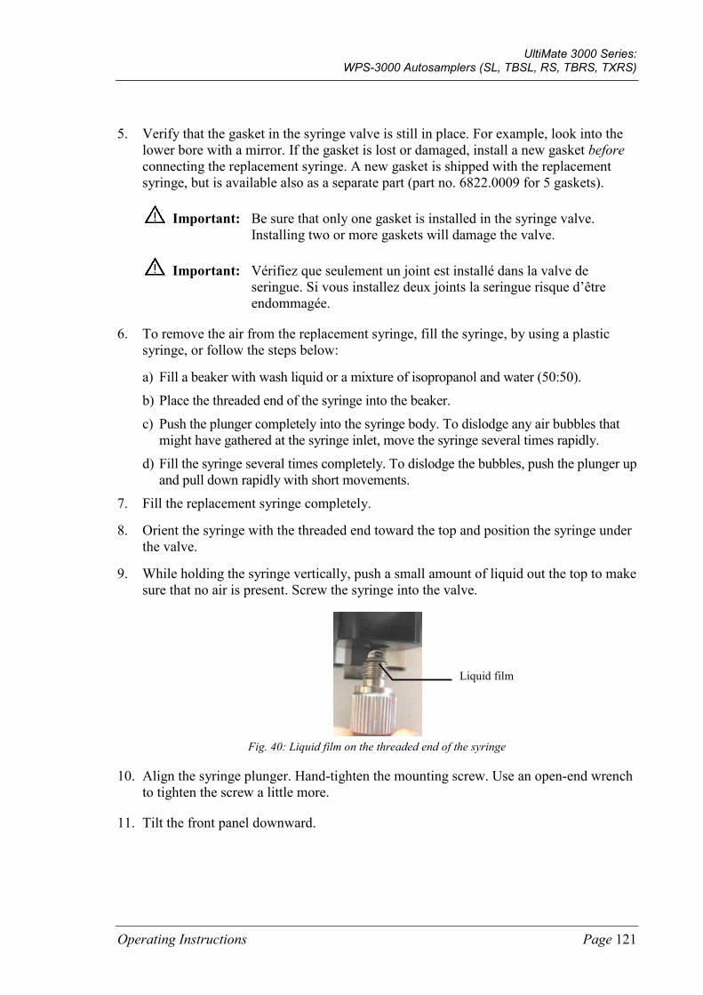
UltiMate 3000 Series: WPS-3000 Autosamplers (SL, TBSL, RS, TBRS, TXRS)
Operating Instructions Page 121
5. Verify that the gasket in the syringe valve is still in place. For example, look into the lower bore with a mirror. If the gasket is lost or damaged, install a new gasket before connecting the replacement syringe. A new gasket is shipped with the replacement syringe, but is available also as a separate part (part no. 6822.0009 for 5 gaskets).
Important: Be sure that only one gasket is installed in the syringe valve. Installing two or more gaskets will damage the valve.
Important: Vérifiez que seulement un joint est installé dans la valve de seringue. Si vous installez deux joints la seringue risque d’être endommagée.
6. To remove the air from the replacement syringe, fill the syringe, by using a plastic syringe, or follow the steps below:
a) Fill a beaker with wash liquid or a mixture of isopropanol and water (50:50).
b) Place the threaded end of the syringe into the beaker.
c) Push the plunger completely into the syringe body. To dislodge any air bubbles that might have gathered at the syringe inlet, move the syringe several times rapidly.
d) Fill the syringe several times completely. To dislodge the bubbles, push the plunger up and pull down rapidly with short movements.
7. Fill the replacement syringe completely.
8. Orient the syringe with the threaded end toward the top and position the syringe under the valve.
9. While holding the syringe vertically, push a small amount of liquid out the top to make sure that no air is present. Screw the syringe into the valve.
Fig. 40: Liquid film on the threaded end of the syringe
10. Align the syringe plunger. Hand-tighten the mounting screw. Use an open-end wrench to tighten the screw a little more.
11. Tilt the front panel downward.
Liquid film

UltiMate 3000 Series: WPS-3000 Autosamplers (SL, TBSL, RS, TBRS, TXRS)
Page 122 Operating Instructions
12. Move the syringe up. On the autosampler display, select the Maintenance menu, and then select Syringe and Up—or— in Chromeleon, perform the TerminateChangeSyringe command.
Important: Before executing either command, verify that the syringe is installed correctly. If it is not, moving the syringe plunger upward may cause damage to the syringe.
Important: Avant d'exécuter n’importe quelle commande, vérifiez que la seringue est installée correctement sinon la seringue risque d’être endommagée au cours du déplacement du piston.
13. Flush the replacement syringe several times (→ section 4.6, page 60). Air in the syringe can influence the measurement results considerably. Before you start the analysis, the syringe must be free of air. If air bubbles are still to be seen in the syringe, repeat the flush procedure.
14. If the size of the replacement syringe is different from the size of the syringe you replaced:
♦ In the Chromeleon Server Configuration, on the Options page for the autosampler, verify that the syringe size matches the syringe installed in the autosampler (→ page 48). If it does not, change the setting. Transfer the new configuration to the autosampler. On the General page, click Send configuration to module (→ page 50).
♦ Verify that you have installed an appropriate sample loop and buffer loop. For details, see page 21.
15. Update the service information in Chromeleon. Perform the SyringeChanged command in Chromeleon.
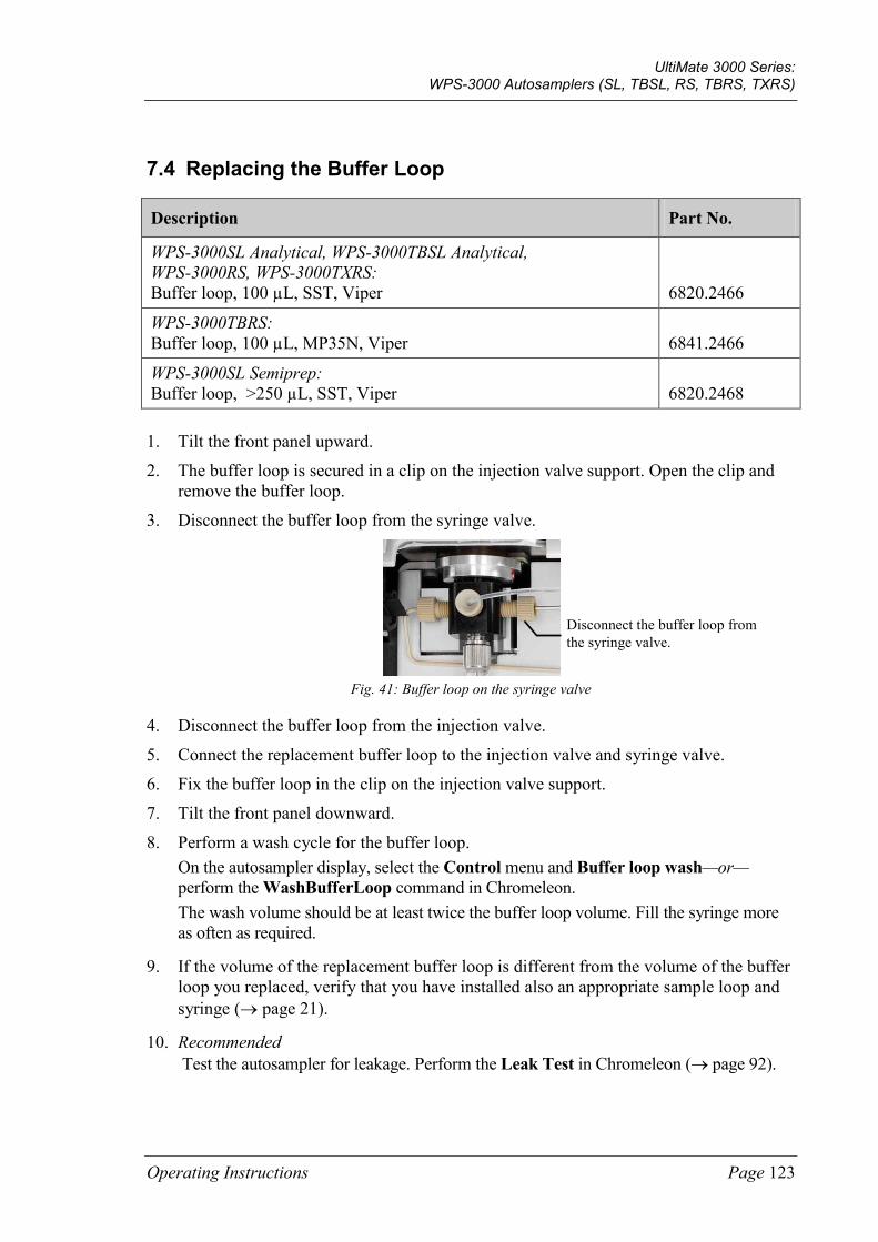
UltiMate 3000 Series: WPS-3000 Autosamplers (SL, TBSL, RS, TBRS, TXRS)
Operating Instructions Page 123
7.4 Replacing the Buffer Loop
Description Part No.
WPS-3000SL Analytical, WPS-3000TBSL Analytical, WPS-3000RS, WPS-3000TXRS: Buffer loop, 100 µL, SST, Viper
6820.2466
WPS-3000TBRS: Buffer loop, 100 µL, MP35N, Viper
6841.2466
WPS-3000SL Semiprep: Buffer loop, >250 µL, SST, Viper
6820.2468
1. Tilt the front panel upward.
2. The buffer loop is secured in a clip on the injection valve support. Open the clip and remove the buffer loop.
3. Disconnect the buffer loop from the syringe valve.
Fig. 41: Buffer loop on the syringe valve
4. Disconnect the buffer loop from the injection valve.
5. Connect the replacement buffer loop to the injection valve and syringe valve.
6. Fix the buffer loop in the clip on the injection valve support.
7. Tilt the front panel downward.
8. Perform a wash cycle for the buffer loop. On the autosampler display, select the Control menu and Buffer loop wash—or—perform the WashBufferLoop command in Chromeleon. The wash volume should be at least twice the buffer loop volume. Fill the syringe more as often as required.
9. If the volume of the replacement buffer loop is different from the volume of the buffer loop you replaced, verify that you have installed also an appropriate sample loop and syringe (→ page 21).
10. Recommended Test the autosampler for leakage. Perform the Leak Test in Chromeleon (→ page 92).
Disconnect the buffer loop from the syringe valve.
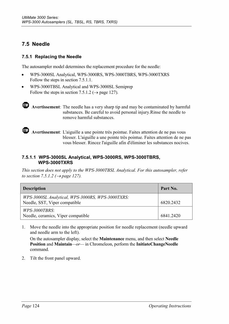
UltiMate 3000 Series: WPS-3000 Autosamplers (SL, TBSL, RS, TBRS, TXRS)
Page 124 Operating Instructions
7.5 Needle
7.5.1 Replacing the Needle
The autosampler model determines the replacement procedure for the needle:
• WPS-3000SL Analytical, WPS-3000RS, WPS-3000TBRS, WPS-3000TXRS Follow the steps in section 7.5.1.1.
• WPS-3000TBSL Analytical and WPS-3000SL Semiprep Follow the steps in section 7.5.1.2 (→ page 127).
Avertissement: The needle has a very sharp tip and may be contaminated by harmful substances. Be careful to avoid personal injury.Rinse the needle to remove harmful substances.
Avertissement: L'aiguille a une pointe très pointue. Faites attention de ne pas vous blesser. L'aiguille a une pointe très pointue. Faites attention de ne pas vous blesser. Rincez l'aiguille afin d'éliminer les substances nocives.
7.5.1.1 WPS-3000SL Analytical, WPS-3000RS, WPS-3000TBRS, WPS-3000TXRS
This section does not apply to the WPS-3000TBSL Analytical. For this autosampler, refer to section 7.5.1.2 (→ page 127).
Description Part No.
WPS-3000SL Analytical, WPS-3000RS, WPS-3000TXRS: Needle, SST, Viper compatible
6820.2432
WPS-3000TBRS: Needle, ceramics, Viper compatible
6841.2420
1. Move the needle into the appropriate position for needle replacement (needle upward and needle arm to the left). On the autosampler display, select the Maintenance menu, and then select Needle Position and Maintain—or— in Chromeleon, perform the InitiateChangeNeedle command.
2. Tilt the front panel upward.
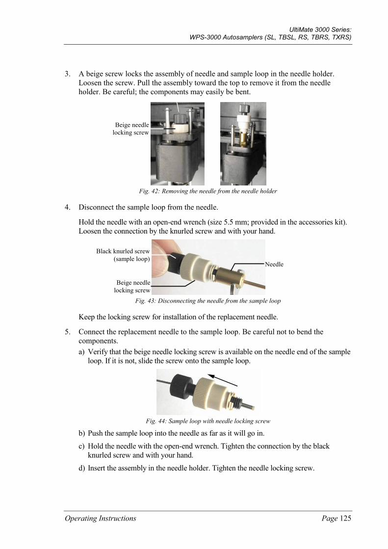
UltiMate 3000 Series: WPS-3000 Autosamplers (SL, TBSL, RS, TBRS, TXRS)
Operating Instructions Page 125
3. A beige screw locks the assembly of needle and sample loop in the needle holder. Loosen the screw. Pull the assembly toward the top to remove it from the needle holder. Be careful; the components may easily be bent.
Fig. 42: Removing the needle from the needle holder
4. Disconnect the sample loop from the needle.
Hold the needle with an open-end wrench (size 5.5 mm; provided in the accessories kit). Loosen the connection by the knurled screw and with your hand.
Fig. 43: Disconnecting the needle from the sample loop
Keep the locking screw for installation of the replacement needle.
5. Connect the replacement needle to the sample loop. Be careful not to bend the components. a) Verify that the beige needle locking screw is available on the needle end of the sample
loop. If it is not, slide the screw onto the sample loop.
Fig. 44: Sample loop with needle locking screw
b) Push the sample loop into the needle as far as it will go in.
c) Hold the needle with the open-end wrench. Tighten the connection by the black knurled screw and with your hand.
d) Insert the assembly in the needle holder. Tighten the needle locking screw.
Beige needle locking screw
Needle
Beige needle locking screw
Black knurled screw (sample loop)
UltiMate 3000 Series: WPS-3000 Autosamplers (SL, TBSL, RS, TBRS, TXRS)
Page 126 Operating Instructions
6. Return the needle arm and needle to the starting positions. On the autosampler display, select the Diagnostics menu, and then select Self test—or—in Chromeleon, perform the SelfTest command.
7. Update the service information in Chromeleon. Perform the NeedleChanged command.
8. Recommended Test the autosampler for leakage. Perform the Leak Test in Chromeleon (→ page 92).
Tip: When you replace the needle, replace also the needle seat (→ page 138).
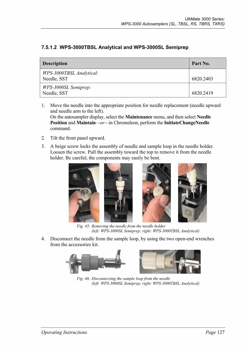
UltiMate 3000 Series: WPS-3000 Autosamplers (SL, TBSL, RS, TBRS, TXRS)
Operating Instructions Page 127
7.5.1.2 WPS-3000TBSL Analytical and WPS-3000SL Semiprep
Description Part No.
WPS-3000TBSL Analytical: Needle, SST
6820.2403
WPS-3000SL Semiprep: Needle, SST
6820.2419
1. Move the needle into the appropriate position for needle replacement (needle upward and needle arm to the left). On the autosampler display, select the Maintenance menu, and then select Needle Position and Maintain—or—in Chromeleon, perform the InitiateChangeNeedle command.
2. Tilt the front panel upward.
3. A beige screw locks the assembly of needle and sample loop in the needle holder. Loosen the screw. Pull the assembly toward the top to remove it from the needle holder. Be careful; the components may easily be bent.
Fig. 45: Removing the needle from the needle holder
(left: WPS-3000SL Semiprep; right: WPS-3000TBSL Analytical)
4. Disconnect the needle from the sample loop, by using the two open-end wrenches from the accessories kit.
Fig. 46: Disconnecting the sample loop from the needle
(left: WPS-3000SL Semiprep; right: WPS-3000TBSL Analytical)
UltiMate 3000 Series: WPS-3000 Autosamplers (SL, TBSL, RS, TBRS, TXRS)
Page 128 Operating Instructions
5. To install the replacement needle, follow the above steps in the reverse order. The needle has a very sharp tip. Be careful to avoid personal injury. To facilitate the installation, two persons should establish the connection between the sample loop and the needle. Push the sample loop into the needle as far as it will go in. Hold both parts in this position and tighten the connection with the open-end wrenches.
6. Return the needle arm and needle to the starting positions. On the autosampler display, select the Diagnostics menu, and then select Self test —or—in Chromeleon, perform the SelfTest command.
7. Update the service information in Chromeleon. Perform the NeedleChanged command.
8. Recommended Test the autosampler for leakage. Perform the Leak Test in Chromeleon (→ page 92).
Tip: When you replace the needle, replace also the needle seat (→ page 138).
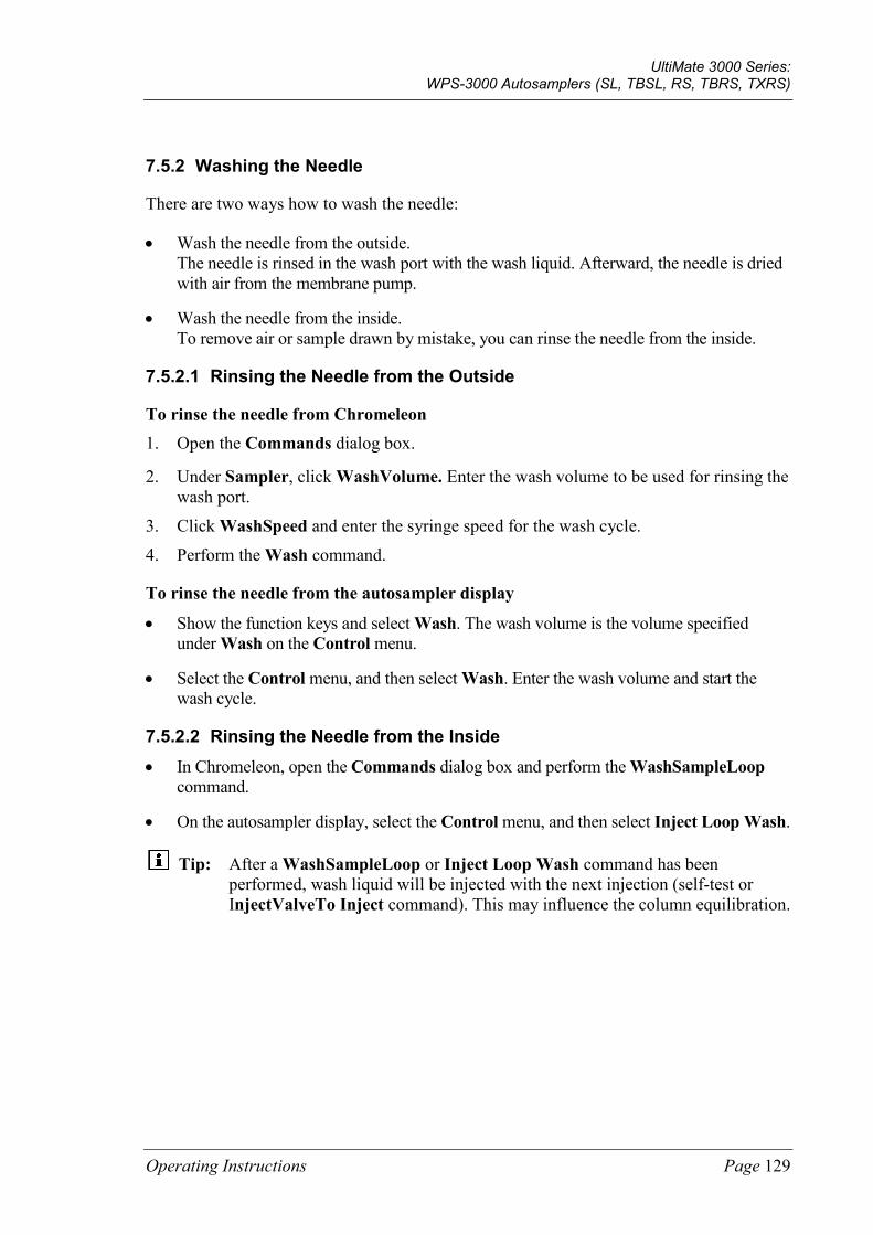
UltiMate 3000 Series: WPS-3000 Autosamplers (SL, TBSL, RS, TBRS, TXRS)
Operating Instructions Page 129
7.5.2 Washing the Needle
There are two ways how to wash the needle:
• Wash the needle from the outside. The needle is rinsed in the wash port with the wash liquid. Afterward, the needle is dried with air from the membrane pump.
• Wash the needle from the inside. To remove air or sample drawn by mistake, you can rinse the needle from the inside.
7.5.2.1 Rinsing the Needle from the Outside
To rinse the needle from Chromeleon 1. Open the Commands dialog box.
2. Under Sampler, click WashVolume. Enter the wash volume to be used for rinsing the wash port.
3. Click WashSpeed and enter the syringe speed for the wash cycle.
4. Perform the Wash command.
To rinse the needle from the autosampler display
• Show the function keys and select Wash. The wash volume is the volume specified under Wash on the Control menu.
• Select the Control menu, and then select Wash. Enter the wash volume and start the wash cycle.
7.5.2.2 Rinsing the Needle from the Inside • In Chromeleon, open the Commands dialog box and perform the WashSampleLoop
command.
• On the autosampler display, select the Control menu, and then select Inject Loop Wash.
Tip: After a WashSampleLoop or Inject Loop Wash command has been performed, wash liquid will be injected with the next injection (self-test or InjectValveTo Inject command). This may influence the column equilibration.
UltiMate 3000 Series: WPS-3000 Autosamplers (SL, TBSL, RS, TBRS, TXRS)
Page 130 Operating Instructions
7.6 Replacing the Sample Loop
The autosampler model determines the replacement procedure for the sample loop. Follow the steps for your autosampler:
• WPS-3000SL Analytical, WPS-3000RS, WPS-3000TBRS, and WPS-3000TXRS: Follow the steps in section 7.6.1.
• WPS-3000TBSL Analytical: Follow the steps in section 7.6.2 (→ page 133)
• WPS-3000SL Semiprep: Follow the steps in section 7.6.3 (→ page 135).
Avertissement: The needle has a very sharp tip and may be contaminated by harmful substances. Be careful to avoid personal injury.Rinse the needle to remove harmful substances.
Avertissement: La boucle d'échantillonnage est reliée a l'aguille. L'aiguille a une pointe très pointue. Faites attention de ne pas vous blesser. L'aiguille a une pointe très pointue. Faites attention de ne pas vous blesser. Rincez l'aiguille afin d'éliminer les substances nocives.
7.6.1 WPS-3000SL Analytical, WPS-3000RS/TBRS/TXRS
This section does not apply to the WPS-3000TBSL Analytical. For this autosampler, refer to section 7.6.2 (→ page 133).
Description Part No.
WPS-3000SL Analytical and WPS-3000RS: Sample loop, analytical, 100 µL (V = 130 µL)1, SST, Viper
6820.2451
WPS-3000TBRS: Sample loop, micro, 25 µL (V = 40 µL)1, MP35N, Viper
6841.2452
WPS-3000TXRS: Sample loop, micro, 25 µL (V = 40 µL)1, SST, Viper
6820.2452
For sample loops that are available as an option, see section 10.2 (→ page 177). 1 The value in front of the parenthesis is the maximum allowed injection volume; the value in parenthesis is the gradient delay volume.
1. Move the needle into the appropriate position for sample loop replacement (needle upward and needle arm to the left). On the autosampler display, select the Maintenance menu, and then select Needle Position and Maintain—or—in Chromeleon, perform the InitiateChangeNeedle command.
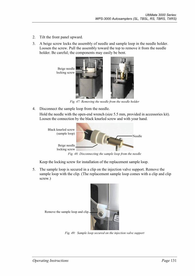
UltiMate 3000 Series: WPS-3000 Autosamplers (SL, TBSL, RS, TBRS, TXRS)
Operating Instructions Page 131
2. Tilt the front panel upward.
3. A beige screw locks the assembly of needle and sample loop in the needle holder. Loosen the screw. Pull the assembly toward the top to remove it from the needle holder. Be careful; the components may easily be bent.
Fig. 47: Removing the needle from the needle holder
4. Disconnect the sample loop from the needle. Hold the needle with the open-end wrench (size 5.5 mm, provided in accessories kit). Loosen the connection by the black knurled screw and with your hand.
Fig. 48: Disconnecting the sample loop from the needle
Keep the locking screw for installation of the replacement sample loop.
5. The sample loop is secured in a clip on the injection valve support. Remove the sample loop with the clip. (The replacement sample loop comes with a clip and clip screw.)
Fig. 49: Sample loop secured on the injection valve support
Remove the sample loop and clip.
Beige needle locking screw
Needle
Beige needle locking screw
Black knurled screw (sample loop)
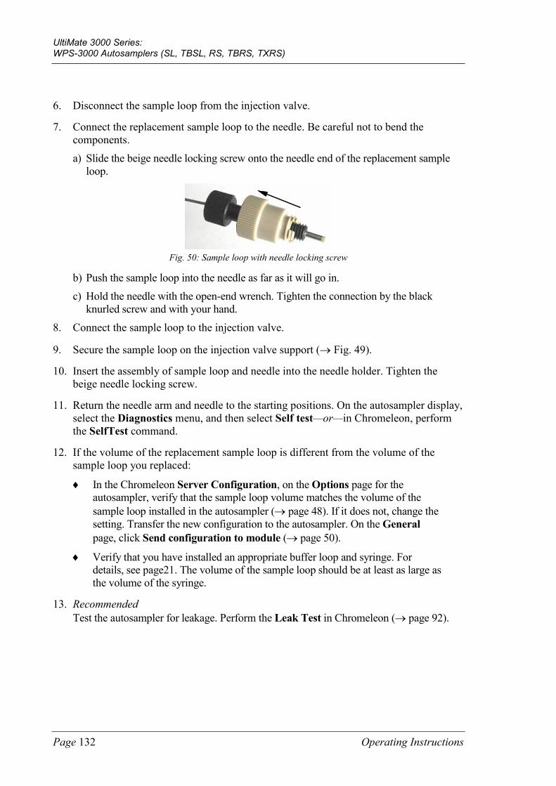
UltiMate 3000 Series: WPS-3000 Autosamplers (SL, TBSL, RS, TBRS, TXRS)
Page 132 Operating Instructions
6. Disconnect the sample loop from the injection valve.
7. Connect the replacement sample loop to the needle. Be careful not to bend the components.
a) Slide the beige needle locking screw onto the needle end of the replacement sample loop.
Fig. 50: Sample loop with needle locking screw
b) Push the sample loop into the needle as far as it will go in. c) Hold the needle with the open-end wrench. Tighten the connection by the black
knurled screw and with your hand.
8. Connect the sample loop to the injection valve.
9. Secure the sample loop on the injection valve support (→ Fig. 49).
10. Insert the assembly of sample loop and needle into the needle holder. Tighten the beige needle locking screw.
11. Return the needle arm and needle to the starting positions. On the autosampler display, select the Diagnostics menu, and then select Self test—or—in Chromeleon, perform the SelfTest command.
12. If the volume of the replacement sample loop is different from the volume of the sample loop you replaced:
♦ In the Chromeleon Server Configuration, on the Options page for the autosampler, verify that the sample loop volume matches the volume of the sample loop installed in the autosampler (→ page 48). If it does not, change the setting. Transfer the new configuration to the autosampler. On the General page, click Send configuration to module (→ page 50).
♦ Verify that you have installed an appropriate buffer loop and syringe. For details, see page21. The volume of the sample loop should be at least as large as the volume of the syringe.
13. Recommended Test the autosampler for leakage. Perform the Leak Test in Chromeleon (→ page 92).
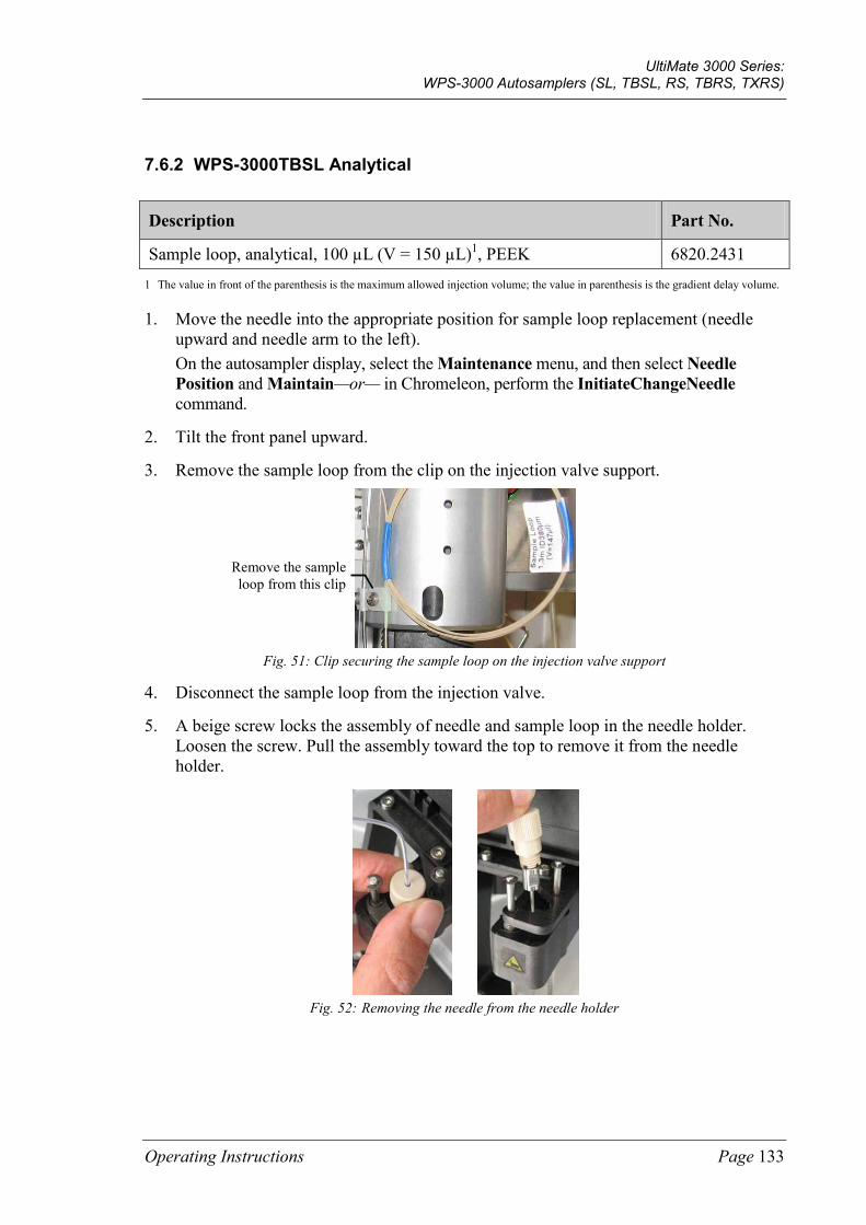
UltiMate 3000 Series: WPS-3000 Autosamplers (SL, TBSL, RS, TBRS, TXRS)
Operating Instructions Page 133
7.6.2 WPS-3000TBSL Analytical
Description Part No.
Sample loop, analytical, 100 µL (V = 150 µL)1, PEEK 6820.2431 1 The value in front of the parenthesis is the maximum allowed injection volume; the value in parenthesis is the gradient delay volume.
1. Move the needle into the appropriate position for sample loop replacement (needle upward and needle arm to the left). On the autosampler display, select the Maintenance menu, and then select Needle Position and Maintain—or— in Chromeleon, perform the InitiateChangeNeedle command.
2. Tilt the front panel upward.
3. Remove the sample loop from the clip on the injection valve support.
Fig. 51: Clip securing the sample loop on the injection valve support
4. Disconnect the sample loop from the injection valve.
5. A beige screw locks the assembly of needle and sample loop in the needle holder. Loosen the screw. Pull the assembly toward the top to remove it from the needle holder.
Fig. 52: Removing the needle from the needle holder
Remove the sample loop from this clip
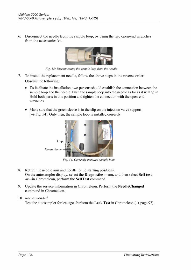
UltiMate 3000 Series: WPS-3000 Autosamplers (SL, TBSL, RS, TBRS, TXRS)
Page 134 Operating Instructions
6. Disconnect the needle from the sample loop, by using the two open-end wrenches from the accessories kit.
Fig. 53: Disconnecting the sample loop from the needle
7. To install the replacement needle, follow the above steps in the reverse order. Observe the following:
♦ To facilitate the installation, two persons should establish the connection between the sample loop and the needle. Push the sample loop into the needle as far as it will go in. Hold both parts in this position and tighten the connection with the open-end wrenches.
♦ Make sure that the green sleeve is in the clip on the injection valve support (→ Fig. 54). Only then, the sample loop is installed correctly.
Fig. 54: Correctly installed sample loop
8. Return the needle arm and needle to the starting positions. On the autosampler display, select the Diagnostics menu, and then select Self test—or—in Chromeleon, perform the SelfTest command.
9. Update the service information in Chromeleon. Perform the NeedleChanged command in Chromeleon.
10. Recommended Test the autosampler for leakage. Perform the Leak Test in Chromeleon (→ page 92).
Green sleeve
Clip
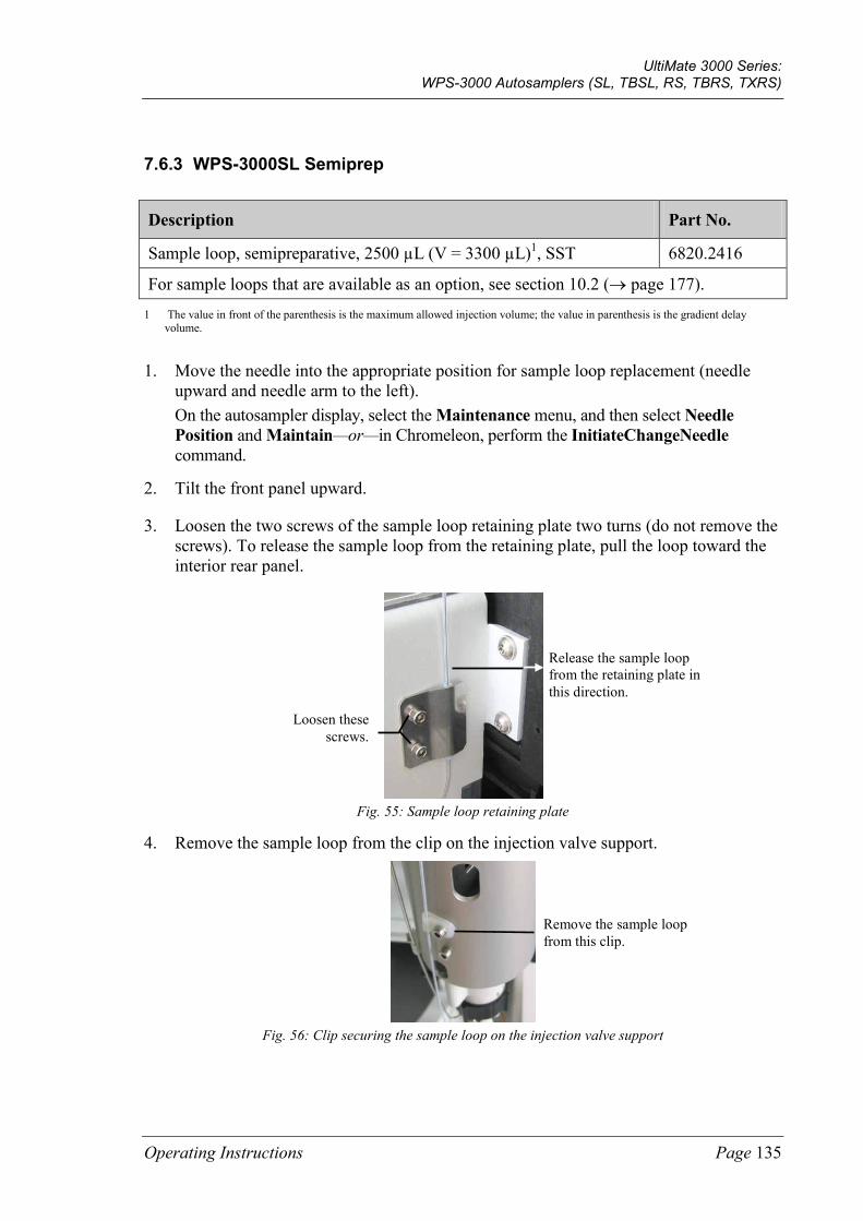
UltiMate 3000 Series: WPS-3000 Autosamplers (SL, TBSL, RS, TBRS, TXRS)
Operating Instructions Page 135
7.6.3 WPS-3000SL Semiprep
Description Part No.
Sample loop, semipreparative, 2500 µL (V = 3300 µL)1, SST 6820.2416
For sample loops that are available as an option, see section 10.2 (→ page 177). 1 The value in front of the parenthesis is the maximum allowed injection volume; the value in parenthesis is the gradient delay
volume.
1. Move the needle into the appropriate position for sample loop replacement (needle upward and needle arm to the left). On the autosampler display, select the Maintenance menu, and then select Needle Position and Maintain—or—in Chromeleon, perform the InitiateChangeNeedle command.
2. Tilt the front panel upward.
3. Loosen the two screws of the sample loop retaining plate two turns (do not remove the screws). To release the sample loop from the retaining plate, pull the loop toward the interior rear panel.
Fig. 55: Sample loop retaining plate
4. Remove the sample loop from the clip on the injection valve support.
Fig. 56: Clip securing the sample loop on the injection valve support
Loosen these screws.
Release the sample loop from the retaining plate in this direction.
Remove the sample loop from this clip.
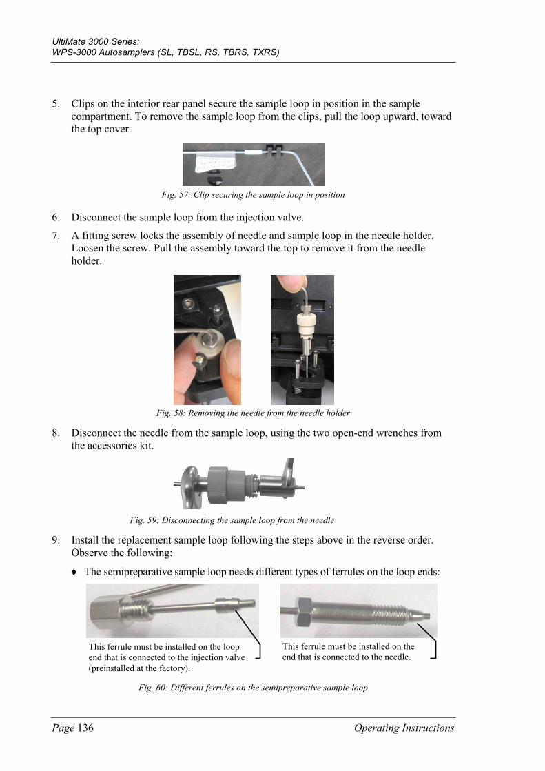
UltiMate 3000 Series: WPS-3000 Autosamplers (SL, TBSL, RS, TBRS, TXRS)
Page 136 Operating Instructions
5. Clips on the interior rear panel secure the sample loop in position in the sample compartment. To remove the sample loop from the clips, pull the loop upward, toward the top cover.
Fig. 57: Clip securing the sample loop in position
6. Disconnect the sample loop from the injection valve.
7. A fitting screw locks the assembly of needle and sample loop in the needle holder. Loosen the screw. Pull the assembly toward the top to remove it from the needle holder.
Fig. 58: Removing the needle from the needle holder
8. Disconnect the needle from the sample loop, using the two open-end wrenches from the accessories kit.
Fig. 59: Disconnecting the sample loop from the needle
9. Install the replacement sample loop following the steps above in the reverse order. Observe the following:
♦ The semipreparative sample loop needs different types of ferrules on the loop ends:
Fig. 60: Different ferrules on the semipreparative sample loop
This ferrule must be installed on the loop end that is connected to the injection valve (preinstalled at the factory).
This ferrule must be installed on the end that is connected to the needle.
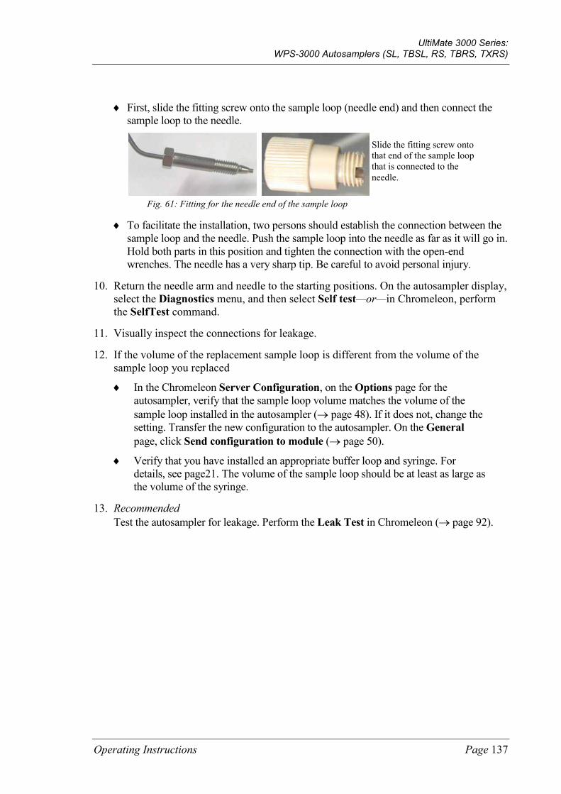
UltiMate 3000 Series: WPS-3000 Autosamplers (SL, TBSL, RS, TBRS, TXRS)
Operating Instructions Page 137
♦ First, slide the fitting screw onto the sample loop (needle end) and then connect the sample loop to the needle.
Fig. 61: Fitting for the needle end of the sample loop
♦ To facilitate the installation, two persons should establish the connection between the sample loop and the needle. Push the sample loop into the needle as far as it will go in. Hold both parts in this position and tighten the connection with the open-end wrenches. The needle has a very sharp tip. Be careful to avoid personal injury.
10. Return the needle arm and needle to the starting positions. On the autosampler display, select the Diagnostics menu, and then select Self test—or—in Chromeleon, perform the SelfTest command.
11. Visually inspect the connections for leakage.
12. If the volume of the replacement sample loop is different from the volume of the sample loop you replaced
♦ In the Chromeleon Server Configuration, on the Options page for the autosampler, verify that the sample loop volume matches the volume of the sample loop installed in the autosampler (→ page 48). If it does not, change the setting. Transfer the new configuration to the autosampler. On the General page, click Send configuration to module (→ page 50).
♦ Verify that you have installed an appropriate buffer loop and syringe. For details, see page21. The volume of the sample loop should be at least as large as the volume of the syringe.
13. Recommended Test the autosampler for leakage. Perform the Leak Test in Chromeleon (→ page 92).
Slide the fitting screw onto that end of the sample loop that is connected to the needle.
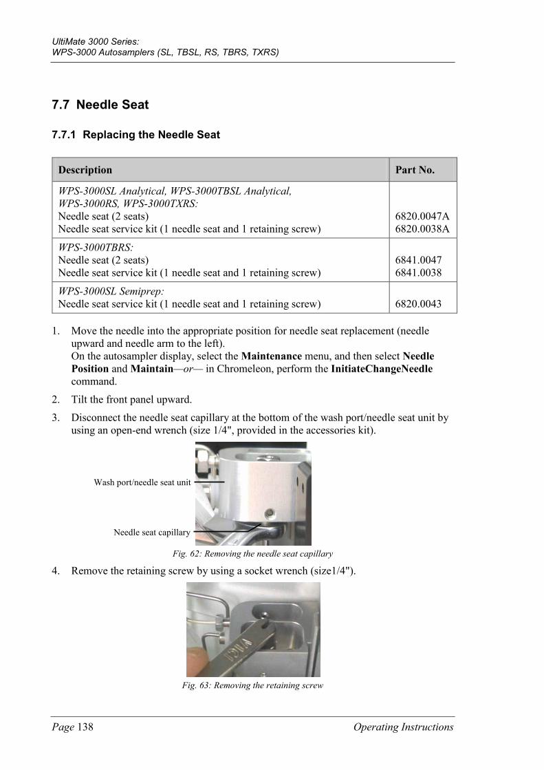
UltiMate 3000 Series: WPS-3000 Autosamplers (SL, TBSL, RS, TBRS, TXRS)
Page 138 Operating Instructions
7.7 Needle Seat
7.7.1 Replacing the Needle Seat
Description Part No.
WPS-3000SL Analytical, WPS-3000TBSL Analytical, WPS-3000RS, WPS-3000TXRS: Needle seat (2 seats) Needle seat service kit (1 needle seat and 1 retaining screw)
6820.0047A 6820.0038A
WPS-3000TBRS: Needle seat (2 seats) Needle seat service kit (1 needle seat and 1 retaining screw)
6841.0047 6841.0038
WPS-3000SL Semiprep: Needle seat service kit (1 needle seat and 1 retaining screw)
6820.0043
1. Move the needle into the appropriate position for needle seat replacement (needle upward and needle arm to the left). On the autosampler display, select the Maintenance menu, and then select Needle Position and Maintain—or— in Chromeleon, perform the InitiateChangeNeedle command.
2. Tilt the front panel upward.
3. Disconnect the needle seat capillary at the bottom of the wash port/needle seat unit by using an open-end wrench (size 1/4", provided in the accessories kit).
Fig. 62: Removing the needle seat capillary
4. Remove the retaining screw by using a socket wrench (size1/4").
Fig. 63: Removing the retaining screw
Needle seat capillary
Wash port/needle seat unit
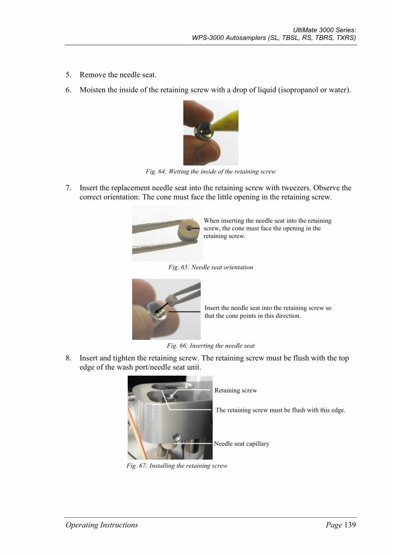
UltiMate 3000 Series: WPS-3000 Autosamplers (SL, TBSL, RS, TBRS, TXRS)
Operating Instructions Page 139
5. Remove the needle seat.
6. Moisten the inside of the retaining screw with a drop of liquid (isopropanol or water).
Fig. 64: Wetting the inside of the retaining screw
7. Insert the replacement needle seat into the retaining screw with tweezers. Observe the correct orientation: The cone must face the little opening in the retaining screw.
Fig. 65: Needle seat orientation
Fig. 66: Inserting the needle seat
8. Insert and tighten the retaining screw. The retaining screw must be flush with the top edge of the wash port/needle seat unit.
Fig. 67: Installing the retaining screw
When inserting the needle seat into the retaining screw, the cone must face the opening in the retaining screw.
Insert the needle seat into the retaining screw so that the cone points in this direction.
Needle seat capillary
Retaining screw
The retaining screw must be flush with this edge.
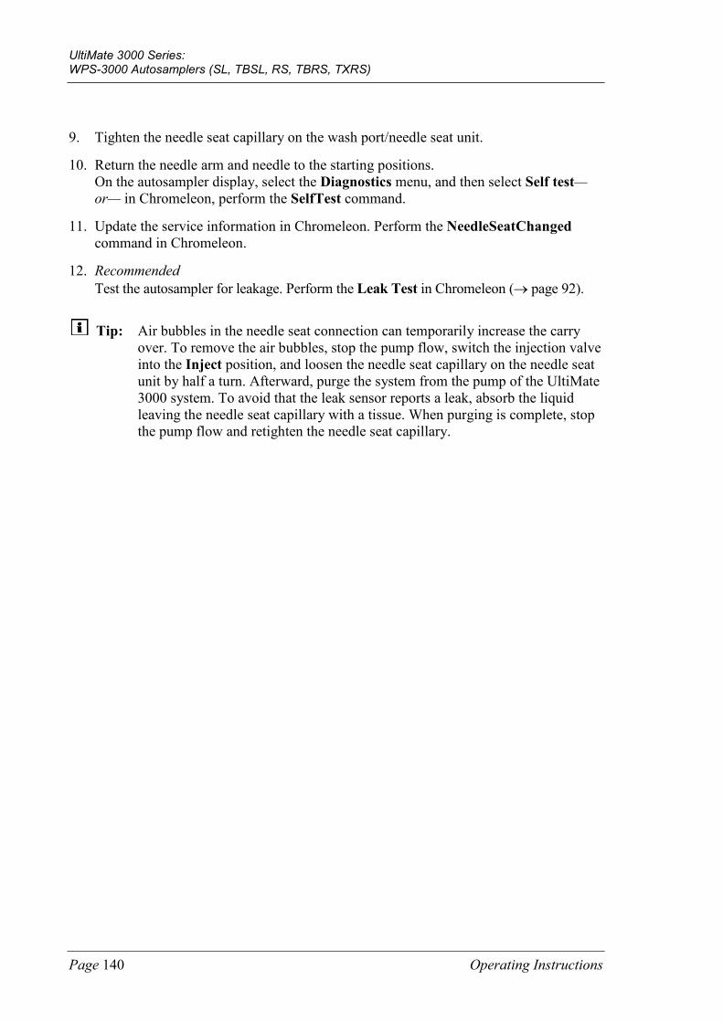
UltiMate 3000 Series: WPS-3000 Autosamplers (SL, TBSL, RS, TBRS, TXRS)
Page 140 Operating Instructions
9. Tighten the needle seat capillary on the wash port/needle seat unit.
10. Return the needle arm and needle to the starting positions. On the autosampler display, select the Diagnostics menu, and then select Self test—or— in Chromeleon, perform the SelfTest command.
11. Update the service information in Chromeleon. Perform the NeedleSeatChanged command in Chromeleon.
12. Recommended Test the autosampler for leakage. Perform the Leak Test in Chromeleon (→ page 92).
Tip: Air bubbles in the needle seat connection can temporarily increase the carry over. To remove the air bubbles, stop the pump flow, switch the injection valve into the Inject position, and loosen the needle seat capillary on the needle seat unit by half a turn. Afterward, purge the system from the pump of the UltiMate 3000 system. To avoid that the leak sensor reports a leak, absorb the liquid leaving the needle seat capillary with a tissue. When purging is complete, stop the pump flow and retighten the needle seat capillary.
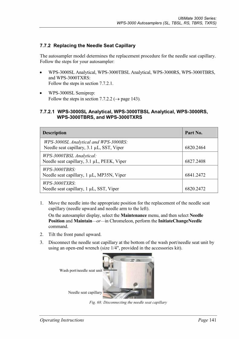
UltiMate 3000 Series: WPS-3000 Autosamplers (SL, TBSL, RS, TBRS, TXRS)
Operating Instructions Page 141
7.7.2 Replacing the Needle Seat Capillary
The autosampler model determines the replacement procedure for the needle seat capillary. Follow the steps for your autosampler:
• WPS-3000SL Analytical, WPS-3000TBSL Analytical, WPS-3000RS, WPS-3000TBRS, and WPS-3000TXRS: Follow the steps in section 7.7.2.1.
• WPS-3000SL Semiprep: Follow the steps in section 7.7.2.2 (→ page 143).
7.7.2.1 WPS-3000SL Analytical, WPS-3000TBSL Analytical, WPS-3000RS, WPS-3000TBRS, and WPS-3000TXRS
Description Part No.
WPS-3000SL Analytical and WPS-3000RS: Needle seat capillary, 3.1 µL, SST, Viper
6820.2464
WPS-3000TBSL Analytical: Needle seat capillary, 3.1 µL, PEEK, Viper
6827.2408
WPS-3000TBRS: Needle seat capillary, 1 µL, MP35N, Viper
6841.2472
WPS-3000TXRS: Needle seat capillary, 1 µL, SST, Viper
6820.2472
1. Move the needle into the appropriate position for the replacement of the needle seat capillary (needle upward and needle arm to the left). On the autosampler display, select the Maintenance menu, and then select Needle Position and Maintain—or—in Chromeleon, perform the InitiateChangeNeedle command.
2. Tilt the front panel upward.
3. Disconnect the needle seat capillary at the bottom of the wash port/needle seat unit by using an open-end wrench (size 1/4", provided in the accessories kit).
Fig. 68: Disconnecting the needle seat capillary
Needle seat capillary
Wash port/needle seat unit
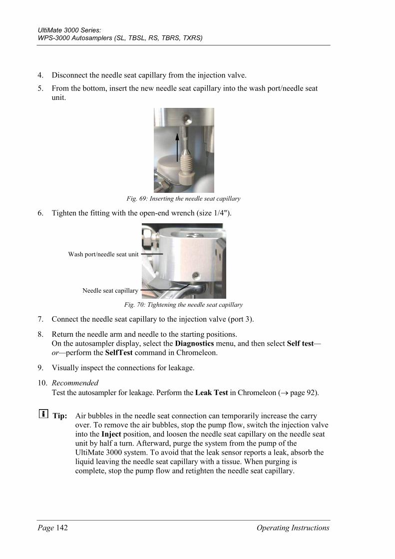
UltiMate 3000 Series: WPS-3000 Autosamplers (SL, TBSL, RS, TBRS, TXRS)
Page 142 Operating Instructions
4. Disconnect the needle seat capillary from the injection valve.
5. From the bottom, insert the new needle seat capillary into the wash port/needle seat unit.
Fig. 69: Inserting the needle seat capillary
6. Tighten the fitting with the open-end wrench (size 1/4").
Fig. 70: Tightening the needle seat capillary
7. Connect the needle seat capillary to the injection valve (port 3).
8. Return the needle arm and needle to the starting positions. On the autosampler display, select the Diagnostics menu, and then select Self test—or—perform the SelfTest command in Chromeleon.
9. Visually inspect the connections for leakage.
10. Recommended Test the autosampler for leakage. Perform the Leak Test in Chromeleon (→ page 92).
Tip: Air bubbles in the needle seat connection can temporarily increase the carry over. To remove the air bubbles, stop the pump flow, switch the injection valve into the Inject position, and loosen the needle seat capillary on the needle seat unit by half a turn. Afterward, purge the system from the pump of the UltiMate 3000 system. To avoid that the leak sensor reports a leak, absorb the liquid leaving the needle seat capillary with a tissue. When purging is complete, stop the pump flow and retighten the needle seat capillary.
Needle seat capillary
Wash port/needle seat unit
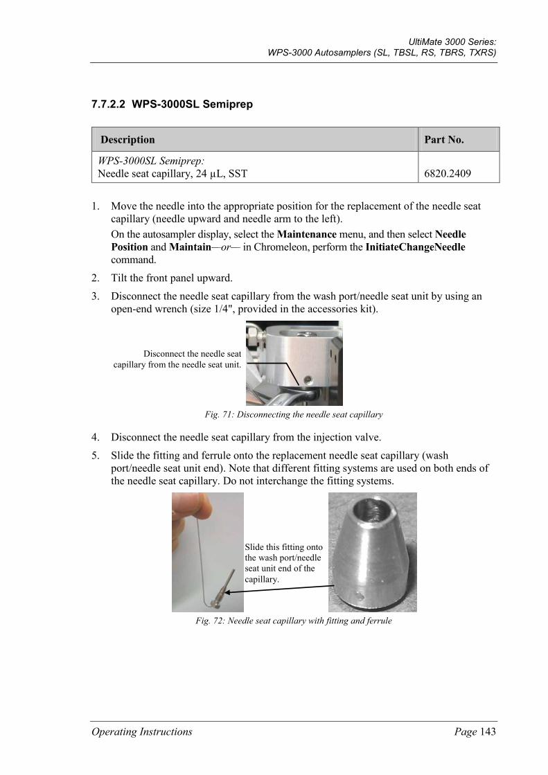
UltiMate 3000 Series: WPS-3000 Autosamplers (SL, TBSL, RS, TBRS, TXRS)
Operating Instructions Page 143
7.7.2.2 WPS-3000SL Semiprep
Description Part No.
WPS-3000SL Semiprep: Needle seat capillary, 24 µL, SST
6820.2409
1. Move the needle into the appropriate position for the replacement of the needle seat capillary (needle upward and needle arm to the left). On the autosampler display, select the Maintenance menu, and then select Needle Position and Maintain—or— in Chromeleon, perform the InitiateChangeNeedle command.
2. Tilt the front panel upward.
3. Disconnect the needle seat capillary from the wash port/needle seat unit by using an open-end wrench (size 1/4", provided in the accessories kit).
Fig. 71: Disconnecting the needle seat capillary
4. Disconnect the needle seat capillary from the injection valve.
5. Slide the fitting and ferrule onto the replacement needle seat capillary (wash port/needle seat unit end). Note that different fitting systems are used on both ends of the needle seat capillary. Do not interchange the fitting systems.
Fig. 72: Needle seat capillary with fitting and ferrule
Disconnect the needle seat capillary from the needle seat unit.
Slide this fitting onto the wash port/needle seat unit end of the capillary.
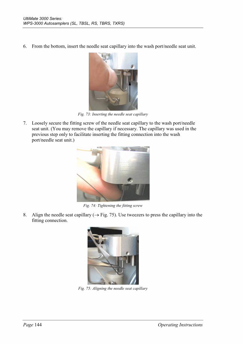
UltiMate 3000 Series: WPS-3000 Autosamplers (SL, TBSL, RS, TBRS, TXRS)
Page 144 Operating Instructions
6. From the bottom, insert the needle seat capillary into the wash port/needle seat unit.
Fig. 73: Inserting the needle seat capillary
7. Loosely secure the fitting screw of the needle seat capillary to the wash port/needle seat unit. (You may remove the capillary if necessary. The capillary was used in the previous step only to facilitate inserting the fitting connection into the wash port/needle seat unit.)
Fig. 74: Tightening the fitting screw
8. Align the needle seat capillary (→ Fig. 75). Use tweezers to press the capillary into the fitting connection.
Fig. 75: Aligning the needle seat capillary
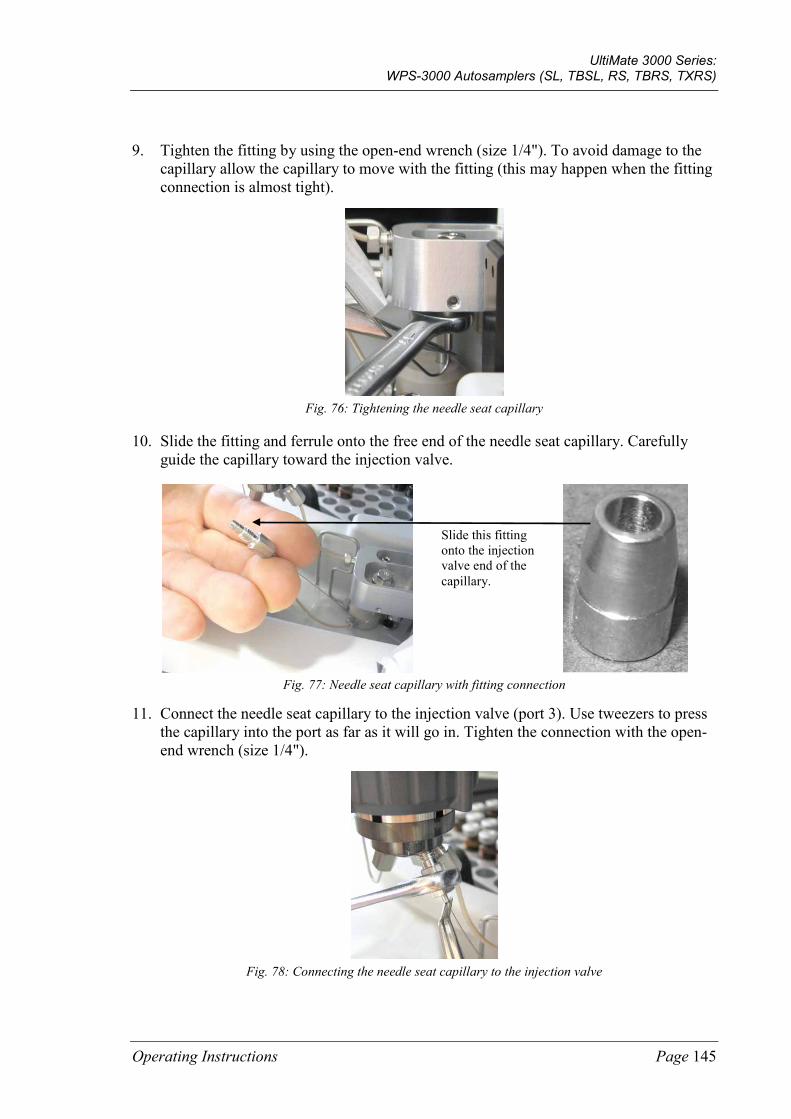
UltiMate 3000 Series: WPS-3000 Autosamplers (SL, TBSL, RS, TBRS, TXRS)
Operating Instructions Page 145
9. Tighten the fitting by using the open-end wrench (size 1/4"). To avoid damage to the capillary allow the capillary to move with the fitting (this may happen when the fitting connection is almost tight).
Fig. 76: Tightening the needle seat capillary
10. Slide the fitting and ferrule onto the free end of the needle seat capillary. Carefully guide the capillary toward the injection valve.
Fig. 77: Needle seat capillary with fitting connection
11. Connect the needle seat capillary to the injection valve (port 3). Use tweezers to press the capillary into the port as far as it will go in. Tighten the connection with the open-end wrench (size 1/4").
Fig. 78: Connecting the needle seat capillary to the injection valve
Slide this fitting onto the injection valve end of the capillary.
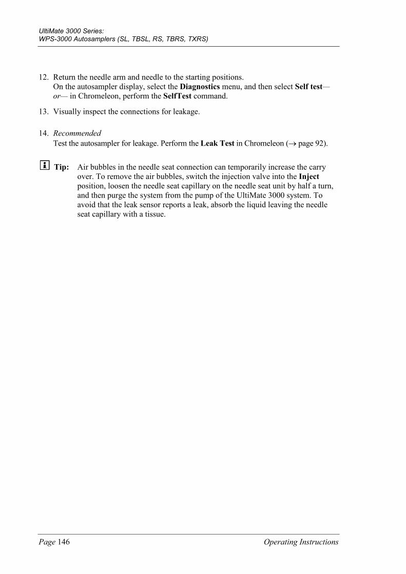
UltiMate 3000 Series: WPS-3000 Autosamplers (SL, TBSL, RS, TBRS, TXRS)
Page 146 Operating Instructions
12. Return the needle arm and needle to the starting positions. On the autosampler display, select the Diagnostics menu, and then select Self test—or— in Chromeleon, perform the SelfTest command.
13. Visually inspect the connections for leakage.
14. Recommended Test the autosampler for leakage. Perform the Leak Test in Chromeleon (→ page 92).
Tip: Air bubbles in the needle seat connection can temporarily increase the carry over. To remove the air bubbles, switch the injection valve into the Inject position, loosen the needle seat capillary on the needle seat unit by half a turn, and then purge the system from the pump of the UltiMate 3000 system. To avoid that the leak sensor reports a leak, absorb the liquid leaving the needle seat capillary with a tissue.
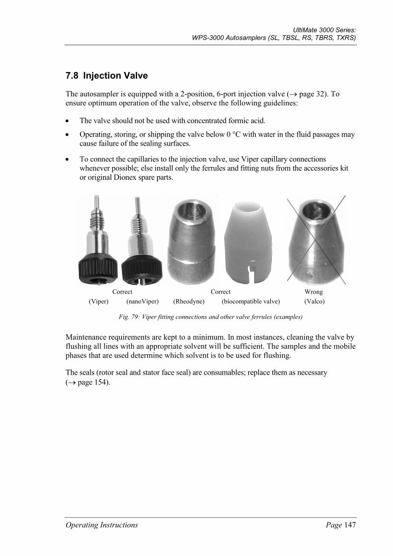
UltiMate 3000 Series: WPS-3000 Autosamplers (SL, TBSL, RS, TBRS, TXRS)
Operating Instructions Page 147
7.8 Injection Valve
The autosampler is equipped with a 2-position, 6-port injection valve (→ page 32). To ensure optimum operation of the valve, observe the following guidelines:
• The valve should not be used with concentrated formic acid.
• Operating, storing, or shipping the valve below 0 °C with water in the fluid passages may cause failure of the sealing surfaces.
• To connect the capillaries to the injection valve, use Viper capillary connections whenever possible; else install only the ferrules and fitting nuts from the accessories kit or original Dionex spare parts.
Correct Correct Wrong (Viper) (nanoViper) (Rheodyne) (biocompatible valve) (Valco)
Fig. 79: Viper fitting connections and other valve ferrules (examples)
Maintenance requirements are kept to a minimum. In most instances, cleaning the valve by flushing all lines with an appropriate solvent will be sufficient. The samples and the mobile phases that are used determine which solvent is to be used for flushing.
The seals (rotor seal and stator face seal) are consumables; replace them as necessary (→ page 154).
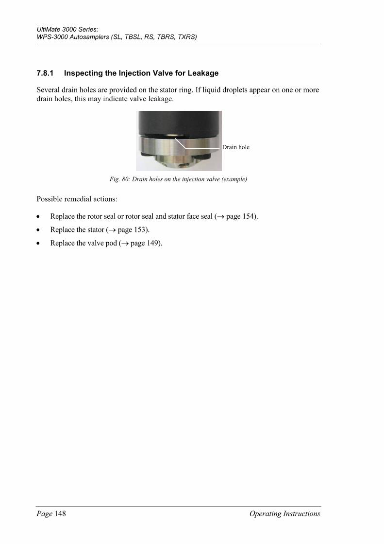
UltiMate 3000 Series: WPS-3000 Autosamplers (SL, TBSL, RS, TBRS, TXRS)
Page 148 Operating Instructions
7.8.1 Inspecting the Injection Valve for Leakage
Several drain holes are provided on the stator ring. If liquid droplets appear on one or more drain holes, this may indicate valve leakage.
Fig. 80: Drain holes on the injection valve (example)
Possible remedial actions:
• Replace the rotor seal or rotor seal and stator face seal (→ page 154).
• Replace the stator (→ page 153).
• Replace the valve pod (→ page 149).
Drain hole
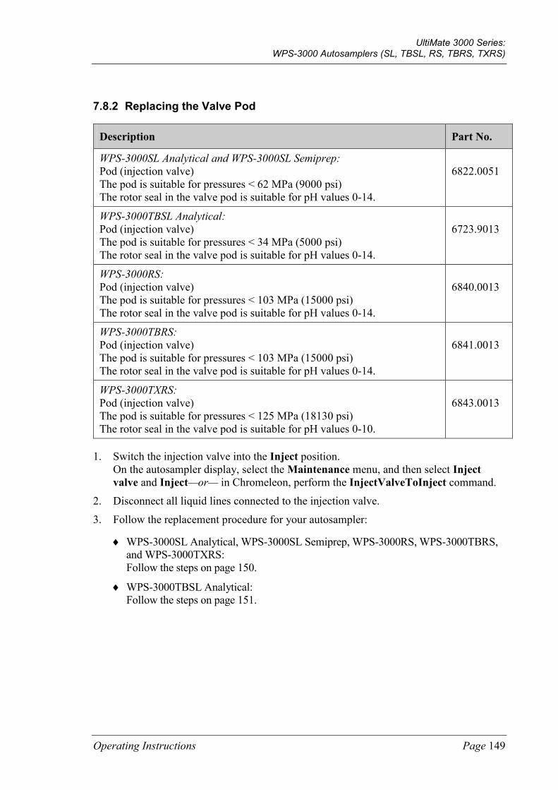
UltiMate 3000 Series: WPS-3000 Autosamplers (SL, TBSL, RS, TBRS, TXRS)
Operating Instructions Page 149
7.8.2 Replacing the Valve Pod
Description Part No.
WPS-3000SL Analytical and WPS-3000SL Semiprep: Pod (injection valve) The pod is suitable for pressures < 62 MPa (9000 psi) The rotor seal in the valve pod is suitable for pH values 0-14.
6822.0051
WPS-3000TBSL Analytical: Pod (injection valve) The pod is suitable for pressures < 34 MPa (5000 psi) The rotor seal in the valve pod is suitable for pH values 0-14.
6723.9013
WPS-3000RS: Pod (injection valve) The pod is suitable for pressures < 103 MPa (15000 psi) The rotor seal in the valve pod is suitable for pH values 0-14.
6840.0013
WPS-3000TBRS: Pod (injection valve) The pod is suitable for pressures < 103 MPa (15000 psi) The rotor seal in the valve pod is suitable for pH values 0-14.
6841.0013
WPS-3000TXRS: Pod (injection valve) The pod is suitable for pressures < 125 MPa (18130 psi) The rotor seal in the valve pod is suitable for pH values 0-10.
6843.0013
1. Switch the injection valve into the Inject position. On the autosampler display, select the Maintenance menu, and then select Inject valve and Inject—or— in Chromeleon, perform the InjectValveToInject command.
2. Disconnect all liquid lines connected to the injection valve.
3. Follow the replacement procedure for your autosampler:
♦ WPS-3000SL Analytical, WPS-3000SL Semiprep, WPS-3000RS, WPS-3000TBRS, and WPS-3000TXRS: Follow the steps on page 150.
♦ WPS-3000TBSL Analytical: Follow the steps on page 151.
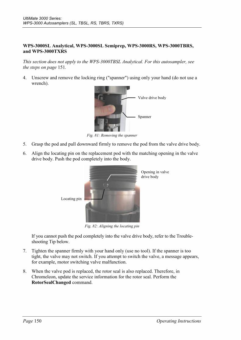
UltiMate 3000 Series: WPS-3000 Autosamplers (SL, TBSL, RS, TBRS, TXRS)
Page 150 Operating Instructions
WPS-3000SL Analytical, WPS-3000SL Semiprep, WPS-3000RS, WPS-3000TBRS, and WPS-3000TXRS
This section does not apply to the WPS-3000TBSL Analytical. For this autosampler, see the steps on page 151.
4. Unscrew and remove the locking ring ("spanner") using only your hand (do not use a wrench).
Fig. 81: Removing the spanner
5. Grasp the pod and pull downward firmly to remove the pod from the valve drive body.
6. Align the locating pin on the replacement pod with the matching opening in the valve drive body. Push the pod completely into the body.
Fig. 82: Aligning the locating pin
If you cannot push the pod completely into the valve drive body, refer to the Trouble-shooting Tip below.
7. Tighten the spanner firmly with your hand only (use no tool). If the spanner is too tight, the valve may not switch. If you attempt to switch the valve, a message appears, for example, motor switching valve malfunction.
8. When the valve pod is replaced, the rotor seal is also replaced. Therefore, in Chromeleon, update the service information for the rotor seal. Perform the RotorSealChanged command.
Valve drive body
Spanner
Locating pin
Opening in valve drive body

UltiMate 3000 Series: WPS-3000 Autosamplers (SL, TBSL, RS, TBRS, TXRS)
Operating Instructions Page 151
Troubleshooting Tip If you cannot push the pod completely into the valve driver body, the position of the valve coupling does not match the position of the valve drive.
1. Switch the valve into the Load position and try again.
2. If you still cannot the push the pod completely into the valve driver body, turn the pod in the valve driver body until the coupling locks in the drive. Continue turning the pod to align the locating pin with the matching opening in the valve driver body, and then push the pod completely into the body.
WPS-3000TBSL Analytical 4. Unscrew and remove the locking ring ("spanner") using only your hand (do not use a
wrench).
Fig. 83: Removing the spanner
5. Afterward, grasp the pod and pull downward firmly to remove the pod from the valve drive body
6. Push the replacement valve completely into the valve drive body. Be sure to install the pod in the correct orientation: Align the large slot in the pod (→ Fig. 84) with the matching runner in the valve drive body.
Fig. 84: Installing the pod
If you cannot push the pod completely into the valve drive body, refer to the Trouble-shooting Tip on page 152.
Spanner
Valve drive body
Runner in the valve drive body Large slot in the pod
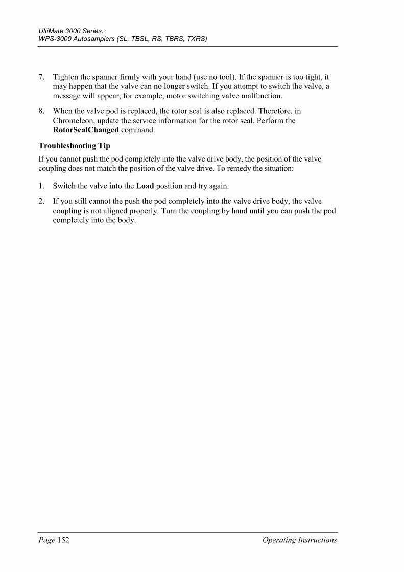
UltiMate 3000 Series: WPS-3000 Autosamplers (SL, TBSL, RS, TBRS, TXRS)
Page 152 Operating Instructions
7. Tighten the spanner firmly with your hand (use no tool). If the spanner is too tight, it may happen that the valve can no longer switch. If you attempt to switch the valve, a message will appear, for example, motor switching valve malfunction.
8. When the valve pod is replaced, the rotor seal is also replaced. Therefore, in Chromeleon, update the service information for the rotor seal. Perform the RotorSealChanged command.
Troubleshooting Tip If you cannot push the pod completely into the valve drive body, the position of the valve coupling does not match the position of the valve drive. To remedy the situation:
1. Switch the valve into the Load position and try again.
2. If you still cannot the push the pod completely into the valve drive body, the valve coupling is not aligned properly. Turn the coupling by hand until you can push the pod completely into the body.
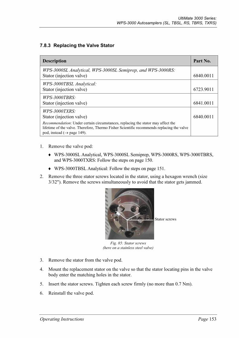
UltiMate 3000 Series: WPS-3000 Autosamplers (SL, TBSL, RS, TBRS, TXRS)
Operating Instructions Page 153
7.8.3 Replacing the Valve Stator
Description Part No.
WPS-3000SL Analytical, WPS-3000SL Semiprep, and WPS-3000RS: Stator (injection valve)
6840.0011
WPS-3000TBSL Analytical: Stator (injection valve)
6723.9011
WPS-3000TBRS: Stator (injection valve)
6841.0011
WPS-3000TXRS: Stator (injection valve)
Recommendation: Under certain circumstances, replacing the stator may affect the lifetime of the valve. Therefore, Thermo Fisher Scientific recommends replacing the valve pod, instead (→ page 149).
6840.0011
1. Remove the valve pod:
♦ WPS-3000SL Analytical, WPS-3000SL Semiprep, WPS-3000RS, WPS-3000TBRS, and WPS-3000TXRS: Follow the steps on page 150.
♦ WPS-3000TBSL Analytical: Follow the steps on page 151. 2. Remove the three stator screws located in the stator, using a hexagon wrench (size
3/32"). Remove the screws simultaneously to avoid that the stator gets jammed.
Fig. 85: Stator screws
(here on a stainless steel valve)
3. Remove the stator from the valve pod.
4. Mount the replacement stator on the valve so that the stator locating pins in the valve body enter the matching holes in the stator.
5. Insert the stator screws. Tighten each screw firmly (no more than 0.7 Nm).
6. Reinstall the valve pod.
Stator screws
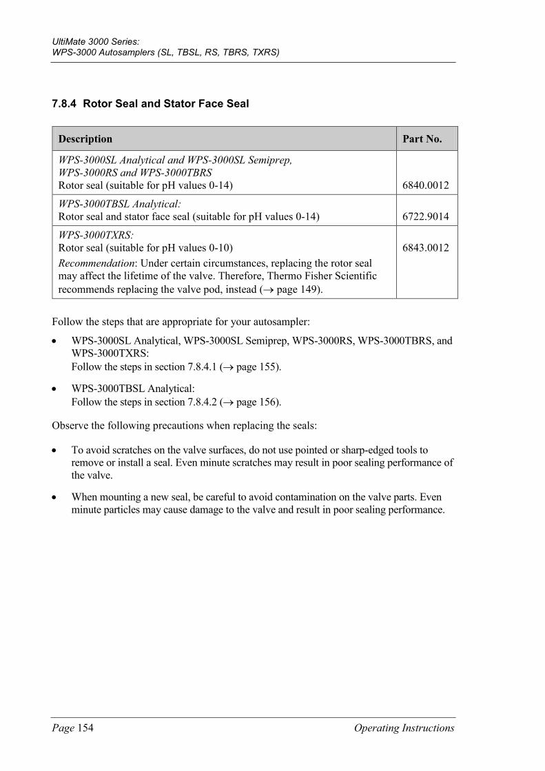
UltiMate 3000 Series: WPS-3000 Autosamplers (SL, TBSL, RS, TBRS, TXRS)
Page 154 Operating Instructions
7.8.4 Rotor Seal and Stator Face Seal
Description Part No.
WPS-3000SL Analytical and WPS-3000SL Semiprep, WPS-3000RS and WPS-3000TBRS Rotor seal (suitable for pH values 0-14)
6840.0012
WPS-3000TBSL Analytical: Rotor seal and stator face seal (suitable for pH values 0-14)
6722.9014
WPS-3000TXRS: Rotor seal (suitable for pH values 0-10) Recommendation: Under certain circumstances, replacing the rotor seal may affect the lifetime of the valve. Therefore, Thermo Fisher Scientific recommends replacing the valve pod, instead (→ page 149).
6843.0012
Follow the steps that are appropriate for your autosampler:
• WPS-3000SL Analytical, WPS-3000SL Semiprep, WPS-3000RS, WPS-3000TBRS, and WPS-3000TXRS: Follow the steps in section 7.8.4.1 (→ page 155).
• WPS-3000TBSL Analytical: Follow the steps in section 7.8.4.2 (→ page 156).
Observe the following precautions when replacing the seals:
• To avoid scratches on the valve surfaces, do not use pointed or sharp-edged tools to remove or install a seal. Even minute scratches may result in poor sealing performance of the valve.
• When mounting a new seal, be careful to avoid contamination on the valve parts. Even minute particles may cause damage to the valve and result in poor sealing performance.
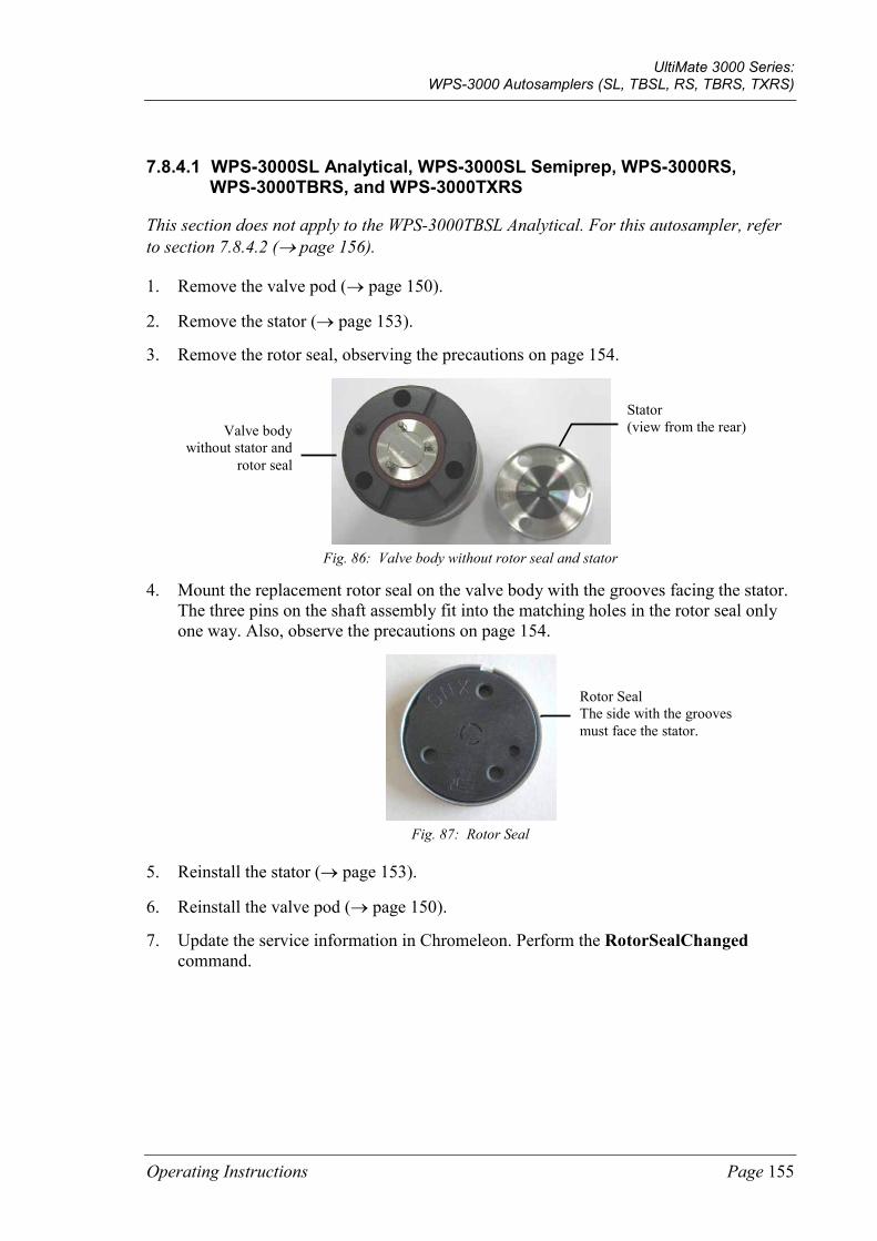
UltiMate 3000 Series: WPS-3000 Autosamplers (SL, TBSL, RS, TBRS, TXRS)
Operating Instructions Page 155
7.8.4.1 WPS-3000SL Analytical, WPS-3000SL Semiprep, WPS-3000RS, WPS-3000TBRS, and WPS-3000TXRS
This section does not apply to the WPS-3000TBSL Analytical. For this autosampler, refer to section 7.8.4.2 (→ page 156).
1. Remove the valve pod (→ page 150).
2. Remove the stator (→ page 153).
3. Remove the rotor seal, observing the precautions on page 154.
Fig. 86: Valve body without rotor seal and stator
4. Mount the replacement rotor seal on the valve body with the grooves facing the stator. The three pins on the shaft assembly fit into the matching holes in the rotor seal only one way. Also, observe the precautions on page 154.
Fig. 87: Rotor Seal
5. Reinstall the stator (→ page 153).
6. Reinstall the valve pod (→ page 150).
7. Update the service information in Chromeleon. Perform the RotorSealChanged command.
Valve body without stator and
rotor seal
Stator (view from the rear)
Rotor Seal The side with the grooves must face the stator.
UltiMate 3000 Series: WPS-3000 Autosamplers (SL, TBSL, RS, TBRS, TXRS)
Page 156 Operating Instructions
7.8.4.2 WPS-3000TBSL Analytical 1. Remove the valve pod (→ page 151).
2. Remove the stator (→ page 153).
3. Remove the rotor seal, observing the precautions on page 154.
4. Mount the replacement rotor seal on the valve body with the grooves facing the stator. The three pins on the shaft assembly fit into the matching holes in the rotor seal only one way (see the installation instructions shipped with the kit.) Also, observe the precautions on page 154
5. Remove the old stator face seal from the stator, observing the precautions on page 154.
6. Mount the replacement stator face seal on the stator. The three pins on the seal fit into the matching holes in the stator only one way. Also, observe the precautions on page 154
7. Reinstall the stator (→ page 153).
8. Reinstall the valve pod (→ page 151).
9. Update the service information in Chromeleon. Perform the RotorSealChanged command.
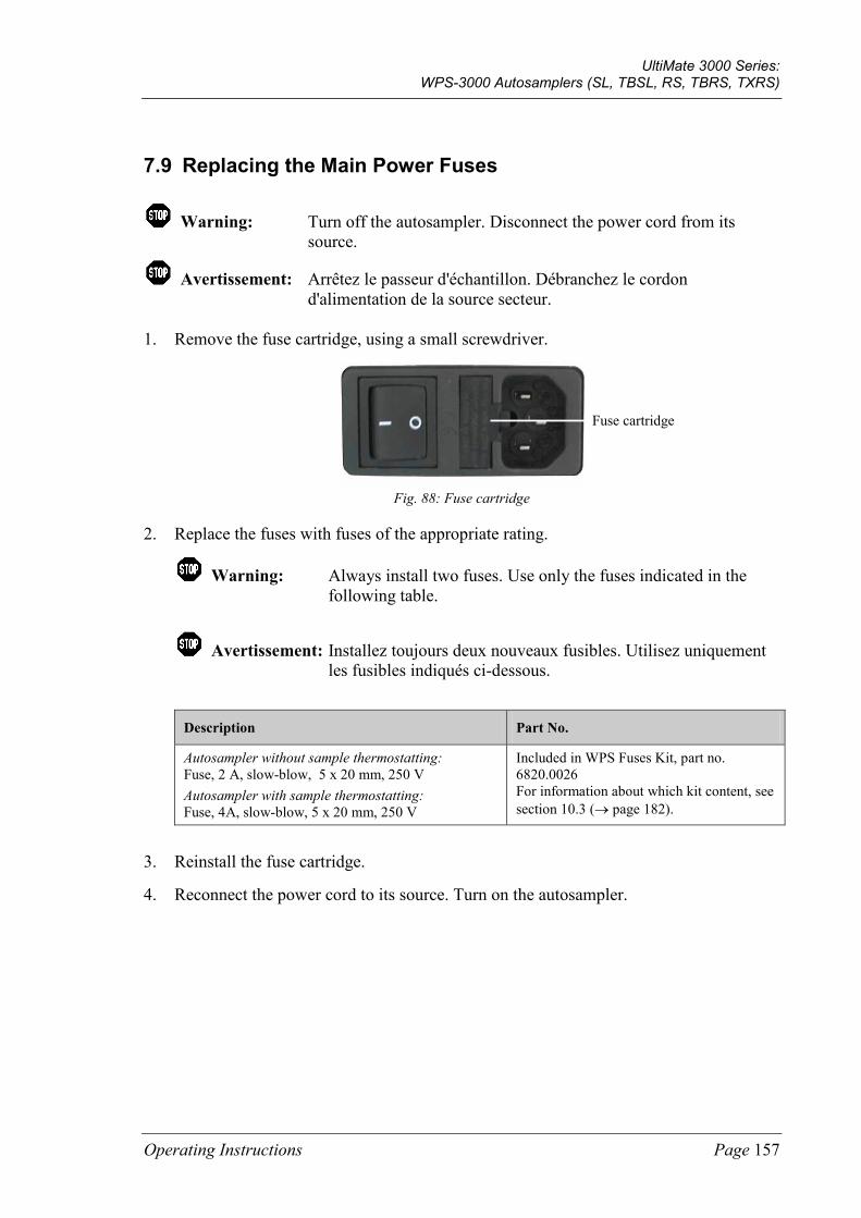
UltiMate 3000 Series: WPS-3000 Autosamplers (SL, TBSL, RS, TBRS, TXRS)
Operating Instructions Page 157
7.9 Replacing the Main Power Fuses
Warning: Turn off the autosampler. Disconnect the power cord from its source.
Avertissement: Arrêtez le passeur d'échantillon. Débranchez le cordon d'alimentation de la source secteur.
1. Remove the fuse cartridge, using a small screwdriver.
Fig. 88: Fuse cartridge
2. Replace the fuses with fuses of the appropriate rating.
Warning: Always install two fuses. Use only the fuses indicated in the following table.
Avertissement: Installez toujours deux nouveaux fusibles. Utilisez uniquement les fusibles indiqués ci-dessous.
Description Part No.
Autosampler without sample thermostatting: Fuse, 2 A, slow-blow, 5 x 20 mm, 250 V Autosampler with sample thermostatting: Fuse, 4A, slow-blow, 5 x 20 mm, 250 V
Included in WPS Fuses Kit, part no. 6820.0026 For information about which kit content, see section 10.3 (→ page 182).
3. Reinstall the fuse cartridge.
4. Reconnect the power cord to its source. Turn on the autosampler.
Fuse cartridge
UltiMate 3000 Series: WPS-3000 Autosamplers (SL, TBSL, RS, TBRS, TXRS)
Page 158 Operating Instructions
7.10 Updating the Autosampler Firmware
The autosampler is shipped with the most recent firmware version. The autosampler firmware is also included in Chromeleon.
To check which firmware version is installed in the autosampler and which version is included in Chromeleon:
• Firmware version installed in the autosampler - Turn on the autosampler via the main power switch on the rear panel. On the front
panel display, general information about autosampler appears, including the firmware version.
- On the Main menu, select Diagnostics (→ page 82), and then select Firmware version.
• Firmware version in Chromeleon In the Windows Explorer, in the IQ folder of your Chromeleon installation, locate the IQReport.log file. In the file, search for UM3_WPS.hex.
Tip: When updating the firmware via Chromeleon, this information is provided also during the download.
Whenever a new firmware version is released for the autosampler, the new version is provided with the next Chromeleon Service Release and described in the release notes.
The new firmware will not be downloaded automatically to the autosampler when you install a Chromeleon Service Release. To update the firmware in the autosampler, follow the steps below:
Important: To ensure that the download is successful, make sure that the communication between the autosampler and Chromeleon is not interrupted during the download and that you do not turn off the autosampler.
Important: Au cours du téléchargement, assurez-vous que la communication entre l'instrument et Chromeleon n'est pas interrompue et n'arrêtez pas l'instrument. Ceci peut entraîner des dysfonctionnements de l'instrument.
1. Before you begin verify that:
♦ The autosampler is connected in Chromeleon. ♦ The Chromeleon server is in running idle mode. All processes on the Chromeleon
server PC and in Chromeleon have been stopped.
2. Start the Server Configuration program (→ page 44).
3. Right-click the autosampler in the timebase and click Properties on the menu.
UltiMate 3000 Series: WPS-3000 Autosamplers (SL, TBSL, RS, TBRS, TXRS)
Operating Instructions Page 159
4. On the General page, click Firmware Download (→ page 45). A message displays the firmware version that is currently installed in the autosampler and the version that will be downloaded from Chromeleon.
Tip: If the autosampler comes with a newer firmware than the version included in Chromeleon, do not downgrade the firmware. Older firmware may be incompatible with new hardware revisions.
5. Click Yes to start the download. (Click No to cancel the action.)
The download can take several minutes. The download is complete when Download completed successfully appears in the Messages Server window in the Chromeleon Server Configuration program. The message appears also in the Chromeleon Audit Trail.
If the download was not successful, one or more messages appear in the Audit Trail. In this case, turn off the autosampler. Turn on the autosampler again and repeat the above steps. If the download fails again, contact Thermo Fisher Scientific Service for Dionex HPLC Products.
Tip: When the download from Chromeleon is complete, an internal download may be performed in the autosampler. If it is, you can monitor the progress on the autosampler display. Do not turn off the autosampler until the internal download is complete.

UltiMate 3000 Series: WPS-3000 Autosamplers (SL, TBSL, RS, TBRS, TXRS)
Page 160 Operating Instructions
UltiMate 3000 Series: WPS-3000 Autosamplers (SL, TBSL, RS, TBRS, TXRS)
Operating Instructions Page 161
8 Optimizing for Special Applications To optimize the WPS-3000RS for application in micro HPLC, you need:
Description Part No.
Sample loop, micro, 25 µL (V = 40 µL), SST, Viper The value in front of the parenthesis is the maximum allowed injection volume; the value in parenthesis is the gradient delay volume.
6820.2452
1. Replace the sample loop (→ page 130).
2. Change the configuration settings for the autosampler in Chromeleon:
a) Open the Properties dialog box for the autosampler (→ page 50).
b) On the Options page, select the Micro check box (→ page 48).
3. Transfer the new configuration settings from Chromeleon to the autosampler. On the General page, click Send configuration to module (→ page 50).
UltiMate 3000 Series: WPS-3000 Autosamplers (SL, TBSL, RS, TBRS, TXRS)
Page 162 Operating Instructions
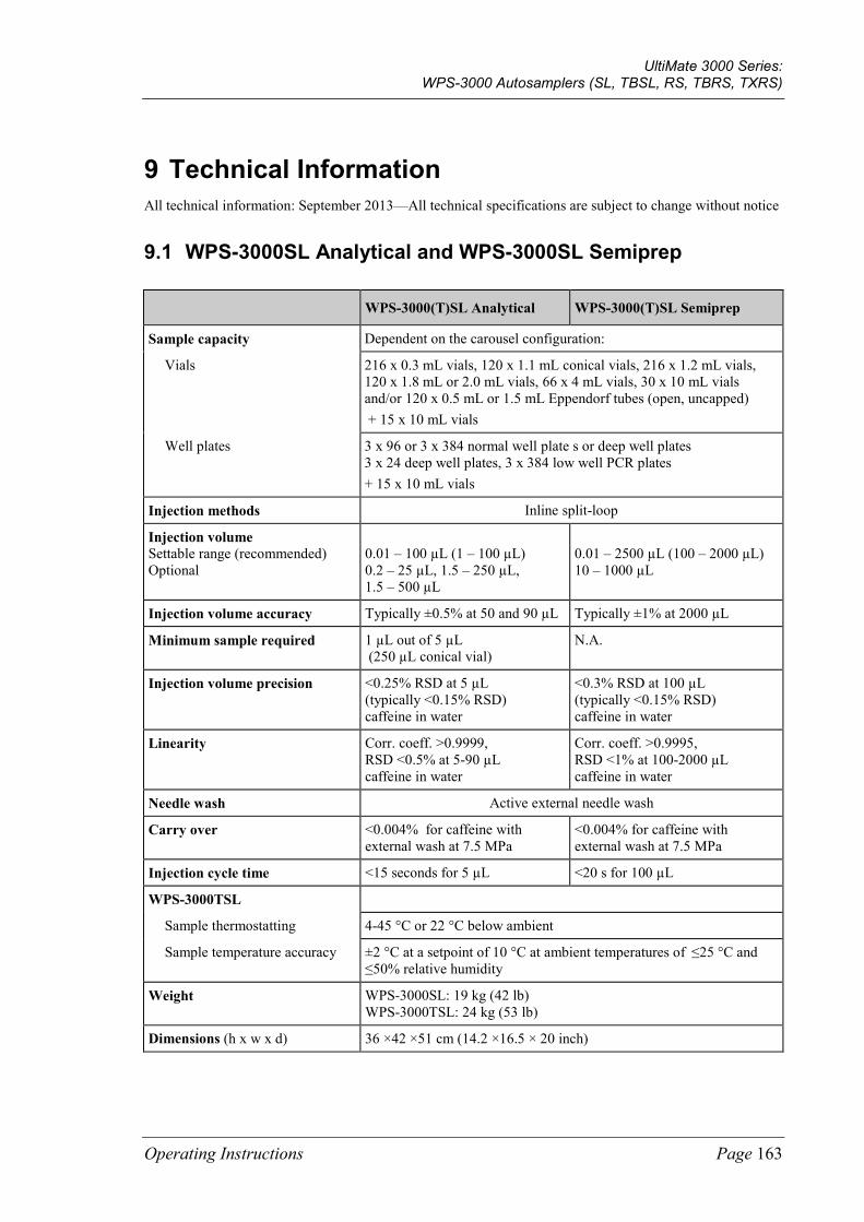
UltiMate 3000 Series: WPS-3000 Autosamplers (SL, TBSL, RS, TBRS, TXRS)
Operating Instructions Page 163
9 Technical Information All technical information: September 2013—All technical specifications are subject to change without notice
9.1 WPS-3000SL Analytical and WPS-3000SL Semiprep
WPS-3000(T)SL Analytical WPS-3000(T)SL Semiprep
Sample capacity Dependent on the carousel configuration:
Vials 216 x 0.3 mL vials, 120 x 1.1 mL conical vials, 216 x 1.2 mL vials, 120 x 1.8 mL or 2.0 mL vials, 66 x 4 mL vials, 30 x 10 mL vials and/or 120 x 0.5 mL or 1.5 mL Eppendorf tubes (open, uncapped) + 15 x 10 mL vials
Well plates 3 x 96 or 3 x 384 normal well plate s or deep well plates 3 x 24 deep well plates, 3 x 384 low well PCR plates + 15 x 10 mL vials
Injection methods Inline split-loop
Injection volume Settable range (recommended) Optional
0.01 – 100 µL (1 – 100 µL) 0.2 – 25 µL, 1.5 – 250 µL, 1.5 – 500 µL
0.01 – 2500 µL (100 – 2000 µL) 10 – 1000 µL
Injection volume accuracy Typically ±0.5% at 50 and 90 µL Typically ±1% at 2000 µL
Minimum sample required 1 µL out of 5 µL (250 µL conical vial)
N.A.
Injection volume precision <0.25% RSD at 5 µL (typically <0.15% RSD) caffeine in water
<0.3% RSD at 100 µL (typically <0.15% RSD) caffeine in water
Linearity Corr. coeff. >0.9999, RSD <0.5% at 5-90 µL caffeine in water
Corr. coeff. >0.9995, RSD <1% at 100-2000 µL caffeine in water
Needle wash Active external needle wash
Carry over <0.004% for caffeine with external wash at 7.5 MPa
<0.004% for caffeine with external wash at 7.5 MPa
Injection cycle time <15 seconds for 5 µL <20 s for 100 µL
WPS-3000TSL
Sample thermostatting 4-45 °C or 22 °C below ambient
Sample temperature accuracy ±2 °C at a setpoint of 10 °C at ambient temperatures of ≤25 °C and ≤50% relative humidity
Weight WPS-3000SL: 19 kg (42 lb) WPS-3000TSL: 24 kg (53 lb)
Dimensions (h x w x d) 36 ×42 ×51 cm (14.2 ×16.5 × 20 inch)
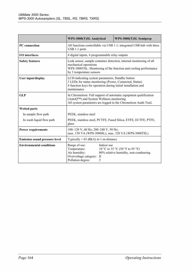
UltiMate 3000 Series: WPS-3000 Autosamplers (SL, TBSL, RS, TBRS, TXRS)
Page 164 Operating Instructions
WPS-3000(T)SL Analytical WPS-3000(T)SL Semiprep
PC connection All functions controllable via USB 1.1; integrated USB hub with three USB 1.1 ports
I/O interfaces 4 digital inputs, 4 programmable relay outputs
Safety features Leak sensor, sample container detection, internal monitoring of all mechanical operations WPS-3000TSL: Monitoring of the function and cooling performance by 3 temperature sensors
User input/display LCD-indicating system parameters, Standby button 3 LEDs for status monitoring (Power, Connected, Status) 4 function keys for operation during initial installation and maintenance
GLP In Chromeleon: Full support of automatic equipment qualification (AutoQ™) and System Wellness monitoring All system parameters are logged in the Chromeleon Audit Trail.
Wetted parts
In sample flow path PEEK, stainless steel
In wash liquid flow path PEEK, stainless steel, PCTFE, Fused Silica, ETFE, ECTFE, PTFE, glass
Power requirements 100–120 V, 60 Hz; 200–240 V, 50 Hz; max. 150 VA (WPS-3000SL), max. 320 VA (WPS-3000TSL)
Emission sound pressure level Typically < 65 dB(A) in 1-m-distance
Environmental conditions Range of use: Indoor use Temperature: 10 °C to 35 °C (50 °F to 95 °F) Air humidity: 80% relative humidity, non-condensing Overvoltage category: II Pollution degree: 2

UltiMate 3000 Series: WPS-3000 Autosamplers (SL, TBSL, RS, TBRS, TXRS)
Operating Instructions Page 165
9.2 WPS-3000TBSL Analytical
WPS-300TBSL Analytical
Sample capacity Dependent on the carousel configuration:
Vials 216 x 0.3 mL vials, 120 x 1.1 mL conical vials, 216 x 1.2 mL vials, 120 x 1.8 mL/2.0 mL vials, 66 x 4 mL vials, 30 x 10 mL vials and/or 120 x 0.5 mL or 1.5 mL Eppendorf tubes (open, uncapped) + 15 x 10 mL vials
Well plates 3 x 96 or 3 x 384 normal well plate s or deep well plates 3 x 24 deep well plates, 3 x 384 low well PCR plates + 15 x 10 mL vials
Injection methods Inline split-loop
Injection volume Settable range (recommended)
0.01 – 100 µL (1 – 100 µL)
Injection volume accuracy Typically ±0.5% at 50 and 90 µL
Minimum sample required 1 µL out of 5 µL (250 µL conical vial)
Injection volume precision <0.25% RSD at 5 µL(typically <0.15% RSD), caffeine in water
Linearity Corr. coeff. >0.9999, RSD <0.5% at 5-90 µL, caffeine in water
Needle wash Active external needle wash
Carry over <0.004% for caffeine with external wash at 7.5 MPa
Injection cycle time <15 seconds for 5 µL
Sample thermostatting 4-45 °C or 22 °C below ambient
Sample temperature accuracy ±2 °C at a setpoint of 10 °C at ambient temperatures of ≤25 °C and ≤50% relative humidity
Weight 24 kg (53 lb)
Dimensions (h x w x d) 36 ×42 ×51 cm (14.2 ×16.5 × 20 inch)
PC connection All functions controllable via USB 1.1; integrated USB hub with three USB 1.1 ports
I/O interfaces 4 digital inputs, 4 programmable relay outputs
Safety features Leak sensor, sample container detection, internal monitoring of all mechanical operations Monitoring of the function and cooling performance by 3 temperature sensors
User input/display LCD-indicating system parameters, Standby button 3 LEDs for status monitoring (Power, Connected, Status) 4 function keys for operation during initial installation and maintenance
GLP In Chromeleon: Full support of automatic equipment qualification (AutoQ™) and System Wellness monitoring All system parameters are logged in the Chromeleon Audit Trail.

UltiMate 3000 Series: WPS-3000 Autosamplers (SL, TBSL, RS, TBRS, TXRS)
Page 166 Operating Instructions
WPS-300TBSL Analytical
Wetted parts
In sample flow path PEEK, stainless steel
In wash liquid flow path PEEK, stainless steel, PCTFE, Fused Silica, ETFE, ECTFE, PTFE, glass
Power requirements 100–120 V, 60 Hz; 200–240 V, 50 Hz; max. 320 VA
Emission sound pressure level Typically < 65 dB(A) in 1-m-distance
Environmental conditions Range of use: Indoor use Temperature: 10 °C to 35 °C (50 °F to 95 °F) Air humidity: 80% relative humidity, non-condensing Overvoltage category: II Pollution degree: 2
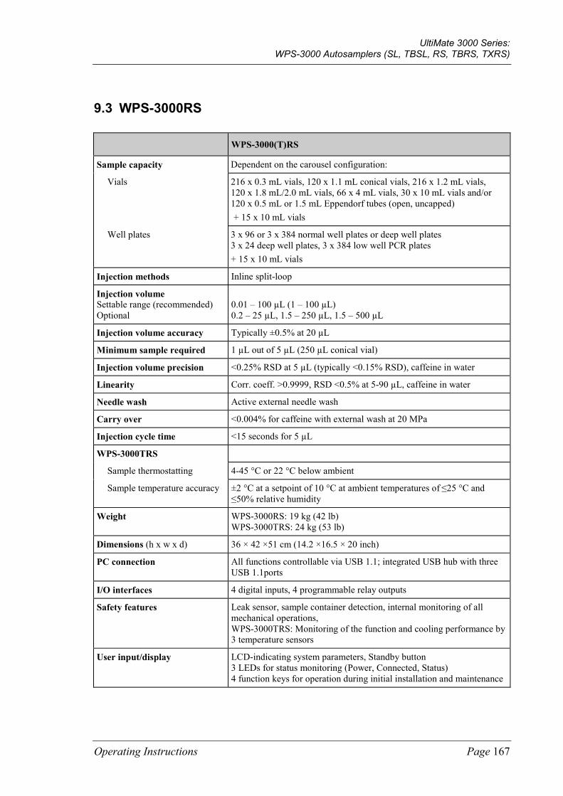
UltiMate 3000 Series: WPS-3000 Autosamplers (SL, TBSL, RS, TBRS, TXRS)
Operating Instructions Page 167
9.3 WPS-3000RS
WPS-3000(T)RS
Sample capacity Dependent on the carousel configuration:
Vials 216 x 0.3 mL vials, 120 x 1.1 mL conical vials, 216 x 1.2 mL vials, 120 x 1.8 mL/2.0 mL vials, 66 x 4 mL vials, 30 x 10 mL vials and/or 120 x 0.5 mL or 1.5 mL Eppendorf tubes (open, uncapped) + 15 x 10 mL vials
Well plates 3 x 96 or 3 x 384 normal well plates or deep well plates 3 x 24 deep well plates, 3 x 384 low well PCR plates + 15 x 10 mL vials
Injection methods Inline split-loop
Injection volume Settable range (recommended) Optional
0.01 – 100 µL (1 – 100 µL) 0.2 – 25 µL, 1.5 – 250 µL, 1.5 – 500 µL
Injection volume accuracy Typically ±0.5% at 20 µL
Minimum sample required 1 µL out of 5 µL (250 µL conical vial)
Injection volume precision <0.25% RSD at 5 µL (typically <0.15% RSD), caffeine in water
Linearity Corr. coeff. >0.9999, RSD <0.5% at 5-90 µL, caffeine in water
Needle wash Active external needle wash
Carry over <0.004% for caffeine with external wash at 20 MPa
Injection cycle time <15 seconds for 5 µL
WPS-3000TRS
Sample thermostatting 4-45 °C or 22 °C below ambient
Sample temperature accuracy ±2 °C at a setpoint of 10 °C at ambient temperatures of ≤25 °C and ≤50% relative humidity
Weight WPS-3000RS: 19 kg (42 lb) WPS-3000TRS: 24 kg (53 lb)
Dimensions (h x w x d) 36 × 42 ×51 cm (14.2 ×16.5 × 20 inch)
PC connection All functions controllable via USB 1.1; integrated USB hub with three USB 1.1ports
I/O interfaces 4 digital inputs, 4 programmable relay outputs
Safety features Leak sensor, sample container detection, internal monitoring of all mechanical operations, WPS-3000TRS: Monitoring of the function and cooling performance by 3 temperature sensors
User input/display LCD-indicating system parameters, Standby button 3 LEDs for status monitoring (Power, Connected, Status) 4 function keys for operation during initial installation and maintenance
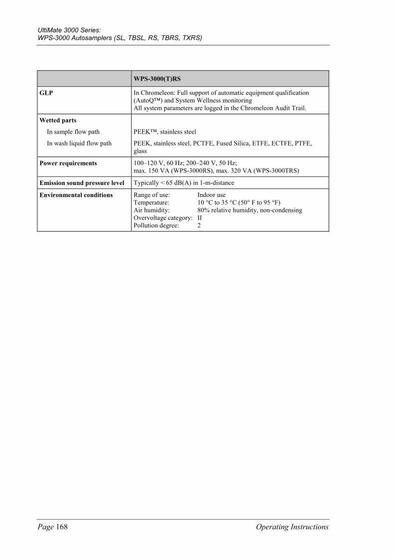
UltiMate 3000 Series: WPS-3000 Autosamplers (SL, TBSL, RS, TBRS, TXRS)
Page 168 Operating Instructions
WPS-3000(T)RS
GLP In Chromeleon: Full support of automatic equipment qualification (AutoQ™) and System Wellness monitoring All system parameters are logged in the Chromeleon Audit Trail.
Wetted parts
In sample flow path PEEK™, stainless steel
In wash liquid flow path PEEK, stainless steel, PCTFE, Fused Silica, ETFE, ECTFE, PTFE, glass
Power requirements 100–120 V, 60 Hz; 200–240 V, 50 Hz; max. 150 VA (WPS-3000RS), max. 320 VA (WPS-3000TRS)
Emission sound pressure level Typically < 65 dB(A) in 1-m-distance
Environmental conditions Range of use: Indoor use Temperature: 10 °C to 35 °C (50° F to 95 °F) Air humidity: 80% relative humidity, non-condensing Overvoltage category: II Pollution degree: 2

UltiMate 3000 Series: WPS-3000 Autosamplers (SL, TBSL, RS, TBRS, TXRS)
Operating Instructions Page 169
9.4 WPS-3000TBRS
WPS-3000TBRS
Sample capacity Dependent on the carousel configuration:
Vials 216 x 0.3 mL vials, 120 x 1.1 mL conical vials, 216 x 1.2 mL vials, 120 x 1.8 mL/2.0 mL vials, 66 x 4 mL vials, 30 x 10 mL vials and/or 120 x 0.5 mL or 1.5 mL Eppendorf tubes (open, uncapped) + 15 x 10 mL vials
Well plates 3 x 96 or 3 x 384 normal well plates or deep well plates 3 x 24 deep well plates, 3 x 384 low well PCR plates + 15 x 10 mL vials
Injection methods Inline split-loop
Injection volume Settable range (recommended) Optional
0.01 - 25 µL (0.2 – 25 µL) 1 – 100 µL, 1.5 – 250 µL, 1.5 – 500 µL
Injection volume accuracy Typically ±0.5% at 20 µL
Minimum sample required 1 µL out of 5 µL (250 µL conical vial)
Injection volume precision <0.3% RSD at 2 µL (typically <0.15% RSD), caffeine in water
Linearity Corr. coeff. >0.9999, RSD <0.5% at 1-20 µL, caffeine in water
Needle wash Active external needle wash
Carry over <0.004% for caffeine with external wash at 20 MPa
Injection cycle time <20 seconds for 5 µL
Sample thermostatting 4-45 °C or 22 °C below ambient
Sample temperature accuracy ±2 °C at a setpoint of 10 °C at ambient temperatures of ≤25 °C and ≤50% relative humidity
Weight 24 kg (53 lb)
Dimensions (h x w x d) 36 × 42 ×51 cm (14.2 ×16.5 × 20 inch)
PC connection All functions controllable via USB 1.1; integrated USB hub with three USB 1.1ports
I/O interfaces 4 digital inputs, 4 programmable relay outputs
Safety features Leak sensor, sample container detection, internal monitoring of all mechanical operations, Monitoring of the function and cooling performance by 3 temperature sensors
User input/display LCD-indicating system parameters, Standby button 3 LEDs for status monitoring (Power, Connected, Status) 4 function keys for operation during initial installation and maintenance
GLP In Chromeleon: Full support of automatic equipment qualification (AutoQ™) and System Wellness monitoring All system parameters are logged in the Chromeleon Audit Trail.

UltiMate 3000 Series: WPS-3000 Autosamplers (SL, TBSL, RS, TBRS, TXRS)
Page 170 Operating Instructions
WPS-3000TBRS
Wetted parts
In sample flow path Ceramics, titanium, PEEK,MP35N
In wash liquid flow path Titanium, PEEK, MP35N, PCTFE, Fused Silica, ETFE, ECTFE, PTFE, glass
Power requirements 100–120 V, 60 Hz; 200–240 V, 50 Hz; max. 320 VA
Emission sound pressure level Typically < 65 dB(A) in 1-m-distance
Environmental conditions Range of use: Indoor use Temperature: 10 °C to 35 °C (50° F to 95 °F) Air humidity: 80% relative humidity, non-condensing Overvoltage category: II Pollution degree: 2
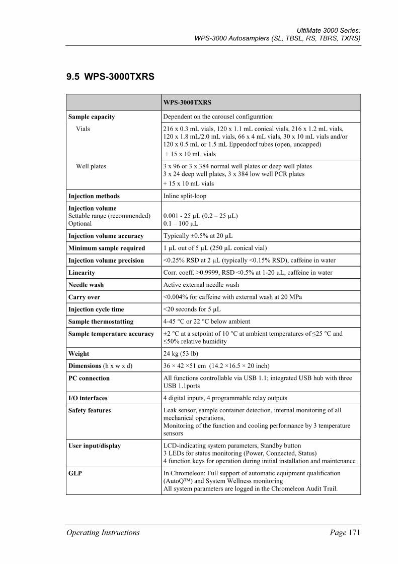
UltiMate 3000 Series: WPS-3000 Autosamplers (SL, TBSL, RS, TBRS, TXRS)
Operating Instructions Page 171
9.5 WPS-3000TXRS
WPS-3000TXRS
Sample capacity Dependent on the carousel configuration:
Vials 216 x 0.3 mL vials, 120 x 1.1 mL conical vials, 216 x 1.2 mL vials, 120 x 1.8 mL/2.0 mL vials, 66 x 4 mL vials, 30 x 10 mL vials and/or 120 x 0.5 mL or 1.5 mL Eppendorf tubes (open, uncapped) + 15 x 10 mL vials
Well plates 3 x 96 or 3 x 384 normal well plates or deep well plates 3 x 24 deep well plates, 3 x 384 low well PCR plates + 15 x 10 mL vials
Injection methods Inline split-loop
Injection volume Settable range (recommended) Optional
0.001 - 25 µL (0.2 – 25 µL) 0.1 – 100 µL
Injection volume accuracy Typically ±0.5% at 20 µL
Minimum sample required 1 µL out of 5 µL (250 µL conical vial)
Injection volume precision <0.25% RSD at 2 µL (typically <0.15% RSD), caffeine in water
Linearity Corr. coeff. >0.9999, RSD <0.5% at 1-20 µL, caffeine in water
Needle wash Active external needle wash
Carry over <0.004% for caffeine with external wash at 20 MPa
Injection cycle time <20 seconds for 5 µL
Sample thermostatting 4-45 °C or 22 °C below ambient
Sample temperature accuracy ±2 °C at a setpoint of 10 °C at ambient temperatures of ≤25 °C and ≤50% relative humidity
Weight 24 kg (53 lb)
Dimensions (h x w x d) 36 × 42 ×51 cm (14.2 ×16.5 × 20 inch)
PC connection All functions controllable via USB 1.1; integrated USB hub with three USB 1.1ports
I/O interfaces 4 digital inputs, 4 programmable relay outputs
Safety features Leak sensor, sample container detection, internal monitoring of all mechanical operations, Monitoring of the function and cooling performance by 3 temperature sensors
User input/display LCD-indicating system parameters, Standby button 3 LEDs for status monitoring (Power, Connected, Status) 4 function keys for operation during initial installation and maintenance
GLP In Chromeleon: Full support of automatic equipment qualification (AutoQ™) and System Wellness monitoring All system parameters are logged in the Chromeleon Audit Trail.
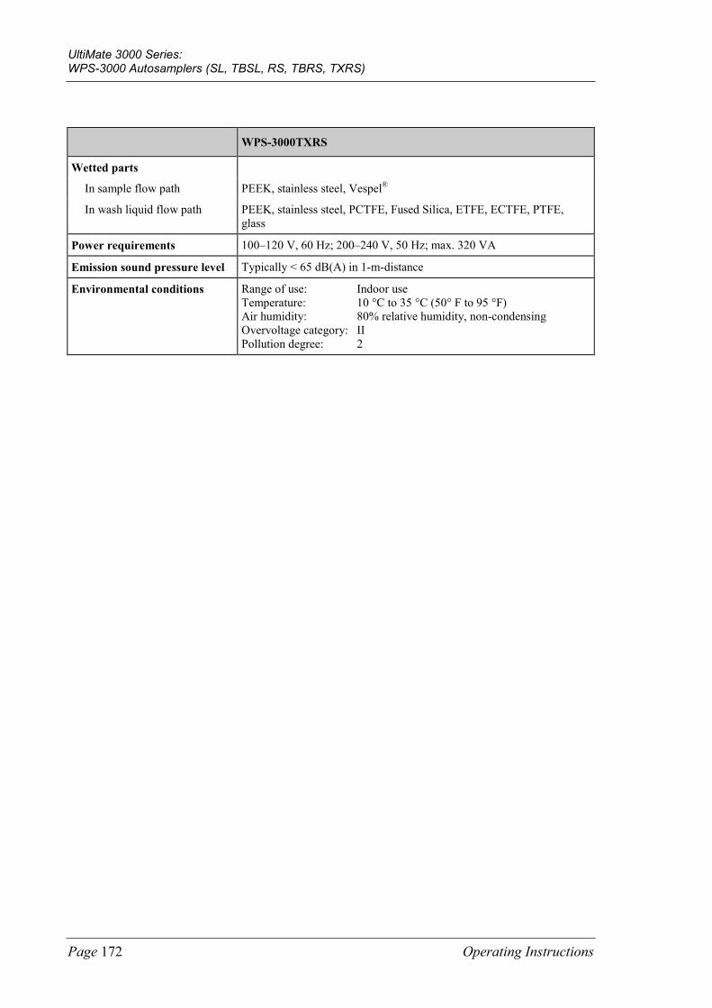
UltiMate 3000 Series: WPS-3000 Autosamplers (SL, TBSL, RS, TBRS, TXRS)
Page 172 Operating Instructions
WPS-3000TXRS
Wetted parts
In sample flow path PEEK, stainless steel, Vespel®
In wash liquid flow path PEEK, stainless steel, PCTFE, Fused Silica, ETFE, ECTFE, PTFE, glass
Power requirements 100–120 V, 60 Hz; 200–240 V, 50 Hz; max. 320 VA
Emission sound pressure level Typically < 65 dB(A) in 1-m-distance
Environmental conditions Range of use: Indoor use Temperature: 10 °C to 35 °C (50° F to 95 °F) Air humidity: 80% relative humidity, non-condensing Overvoltage category: II Pollution degree: 2

UltiMate 3000 Series: WPS-3000 Autosamplers (SL, TBSL, RS, TBRS, TXRS)
Operating Instructions Page 173
10 Accessories, Spare Parts, and Consumables Accessories, spare parts, and consumables for the autosampler are always maintained at the latest technical standard. Therefore, part numbers are subject to alteration. However, updated parts will always be compatible with the parts they replace.
10.1 Standard Accessories
The following accessories are shipped with the autosampler. (The list is subject to change without notice). Some parts listed in the following tables are included in one of the spare part kits. For information about these kits, see section 10.3 (→ page 182).
The part number always refers to the packing unit. Unless otherwise stated, the packing unit is 1 unit. For more information, contact the Thermo Fisher Scientific sales organization for Dionex HPLC Products.
Description Part No. Quantity in the accessories kit
Accessories kit for WPS-3000SL Analytical, WPS-3000RS, and WPS-3000TXRS, including:
Online degas wash kit (The kit includes all tubes and fittings required to connect the wash liquid for online degassing.)
6820.2450 1
Rack for 40 vials, O.D. < 12 mm and normal well plate (12 - 24 mm high)
6820.4070 3
Wash liquid reservoir Included in 6820.4075 1
Fuse, 2 A, slow-blow (5 x 20 mm) Included in 6820.0026 2
Fuse, 4 A, slow-blow (5 x 20 mm) Included in 6820.0026 2
Fuse, 10 A, slow-blow (6.3 x 32 mm) Included in 6820.0026 1
(Double) open-end wrench (size ¼" x 5/16") 6000.0051 1
Open-end wrench (size 5.5 mm) 6146.1225 1
Open-end wrench (size 3/16") 6146.1231 1
Hexagon wrench (size 9/64" ) 6000.0053 1
Hexagon wrench (size 2.5 mm) 6146.2625 1
96 normal well plate 6820.4100 1
1.8 mL vials (amber) Included in 6000.0072 10
Crimp cap and septum for 1.8 mL vial Included in 6000.0071 10
2 mL vials, screw top (cylindrical, amber) Included in 6000.0060 10
Screw cap, white, for 2 mL vial Included in 6000.0057 10
Seal, red, for 2 mL vial Included in 6000.0058 10
10 mL vials (cylindrical) with cap and seal Included in 6820.0023 16
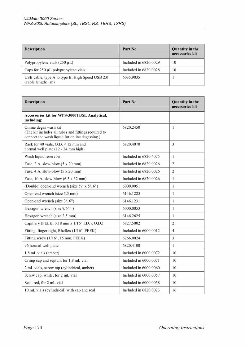
UltiMate 3000 Series: WPS-3000 Autosamplers (SL, TBSL, RS, TBRS, TXRS)
Page 174 Operating Instructions
Description Part No. Quantity in the accessories kit
Polypropylene vials (250 µL) Included in 6820.0029 10
Caps for 250 µL polypropylene vials Included in 6820.0028 10
USB cable, type A to type B, High Speed USB 2.0 (cable length: 1m)
6035.9035 1
Description Part No. Quantity in the accessories kit
Accessories kit for WPS-3000TBSL Analytical, including:
Online degas wash kit (The kit includes all tubes and fittings required to connect the wash liquid for online degassing.)
6820.2450 1
Rack for 40 vials, O.D. < 12 mm and normal well plate (12 - 24 mm high)
6820.4070 3
Wash liquid reservoir Included in 6820.4075 1
Fuse, 2 A, slow-blow (5 x 20 mm) Included in 6820.0026 2
Fuse, 4 A, slow-blow (5 x 20 mm) Included in 6820.0026 2
Fuse, 10 A, slow-blow (6.3 x 32 mm) Included in 6820.0026 1
(Double) open-end wrench (size ¼" x 5/16") 6000.0051 1
Open-end wrench (size 5.5 mm) 6146.1225 1
Open-end wrench (size 3/16") 6146.1231 1
Hexagon wrench (size 9/64" ) 6000.0053 1
Hexagon wrench (size 2.5 mm) 6146.2625 1
Capillary (PEEK, 0.18 mm x 1/16" I.D. x O.D.) 6827.5002 2
Fitting, finger tight, Rheflex (1/16", PEEK) Included in 6000.0012 4
Fitting screw (1/16", 15 mm, PEEK) 6266.0024 3
96 normal well plate 6820.4100 1
1.8 mL vials (amber) Included in 6000.0072 10
Crimp cap and septum for 1.8 mL vial Included in 6000.0071 10
2 mL vials, screw top (cylindrical, amber) Included in 6000.0060 10
Screw cap, white, for 2 mL vial Included in 6000.0057 10
Seal, red, for 2 mL vial Included in 6000.0058 10
10 mL vials (cylindrical) with cap and seal Included in 6820.0023 16
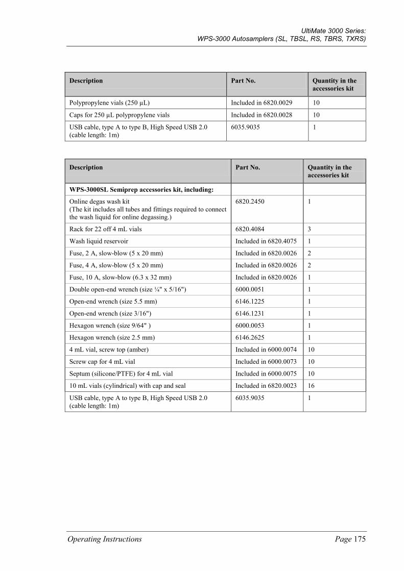
UltiMate 3000 Series: WPS-3000 Autosamplers (SL, TBSL, RS, TBRS, TXRS)
Operating Instructions Page 175
Description Part No. Quantity in the accessories kit
Polypropylene vials (250 µL) Included in 6820.0029 10
Caps for 250 µL polypropylene vials Included in 6820.0028 10
USB cable, type A to type B, High Speed USB 2.0 (cable length: 1m)
6035.9035 1
Description Part No. Quantity in the accessories kit
WPS-3000SL Semiprep accessories kit, including:
Online degas wash kit (The kit includes all tubes and fittings required to connect the wash liquid for online degassing.)
6820.2450 1
Rack for 22 off 4 mL vials 6820.4084 3
Wash liquid reservoir Included in 6820.4075 1
Fuse, 2 A, slow-blow (5 x 20 mm) Included in 6820.0026 2
Fuse, 4 A, slow-blow (5 x 20 mm) Included in 6820.0026 2
Fuse, 10 A, slow-blow (6.3 x 32 mm) Included in 6820.0026 1
Double open-end wrench (size ¼" x 5/16") 6000.0051 1
Open-end wrench (size 5.5 mm) 6146.1225 1
Open-end wrench (size 3/16") 6146.1231 1
Hexagon wrench (size 9/64" ) 6000.0053 1
Hexagon wrench (size 2.5 mm) 6146.2625 1
4 mL vial, screw top (amber) Included in 6000.0074 10
Screw cap for 4 mL vial Included in 6000.0073 10
Septum (silicone/PTFE) for 4 mL vial Included in 6000.0075 10
10 mL vials (cylindrical) with cap and seal Included in 6820.0023 16
USB cable, type A to type B, High Speed USB 2.0 (cable length: 1m)
6035.9035 1
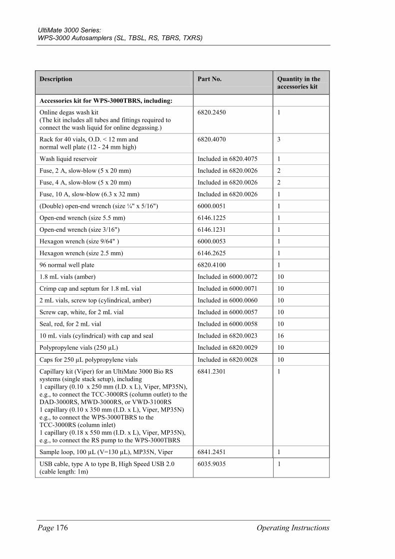
UltiMate 3000 Series: WPS-3000 Autosamplers (SL, TBSL, RS, TBRS, TXRS)
Page 176 Operating Instructions
Description Part No. Quantity in the accessories kit
Accessories kit for WPS-3000TBRS, including:
Online degas wash kit (The kit includes all tubes and fittings required to connect the wash liquid for online degassing.)
6820.2450 1
Rack for 40 vials, O.D. < 12 mm and normal well plate (12 - 24 mm high)
6820.4070 3
Wash liquid reservoir Included in 6820.4075 1
Fuse, 2 A, slow-blow (5 x 20 mm) Included in 6820.0026 2
Fuse, 4 A, slow-blow (5 x 20 mm) Included in 6820.0026 2
Fuse, 10 A, slow-blow (6.3 x 32 mm) Included in 6820.0026 1
(Double) open-end wrench (size ¼" x 5/16") 6000.0051 1
Open-end wrench (size 5.5 mm) 6146.1225 1
Open-end wrench (size 3/16") 6146.1231 1
Hexagon wrench (size 9/64" ) 6000.0053 1
Hexagon wrench (size 2.5 mm) 6146.2625 1
96 normal well plate 6820.4100 1
1.8 mL vials (amber) Included in 6000.0072 10
Crimp cap and septum for 1.8 mL vial Included in 6000.0071 10
2 mL vials, screw top (cylindrical, amber) Included in 6000.0060 10
Screw cap, white, for 2 mL vial Included in 6000.0057 10
Seal, red, for 2 mL vial Included in 6000.0058 10
10 mL vials (cylindrical) with cap and seal Included in 6820.0023 16
Polypropylene vials (250 µL) Included in 6820.0029 10
Caps for 250 µL polypropylene vials Included in 6820.0028 10
Capillary kit (Viper) for an UltiMate 3000 Bio RS systems (single stack setup), including 1 capillary (0.10 x 250 mm (I.D. x L), Viper, MP35N), e.g., to connect the TCC-3000RS (column outlet) to the DAD-3000RS, MWD-3000RS, or VWD-3100RS 1 capillary (0.10 x 350 mm (I.D. x L), Viper, MP35N) e.g., to connect the WPS-3000TBRS to the TCC-3000RS (column inlet) 1 capillary (0.18 x 550 mm (I.D. x L), Viper, MP35N), e.g., to connect the RS pump to the WPS-3000TBRS
6841.2301 1
Sample loop, 100 µL (V=130 µL), MP35N, Viper 6841.2451 1
USB cable, type A to type B, High Speed USB 2.0 (cable length: 1m)
6035.9035 1
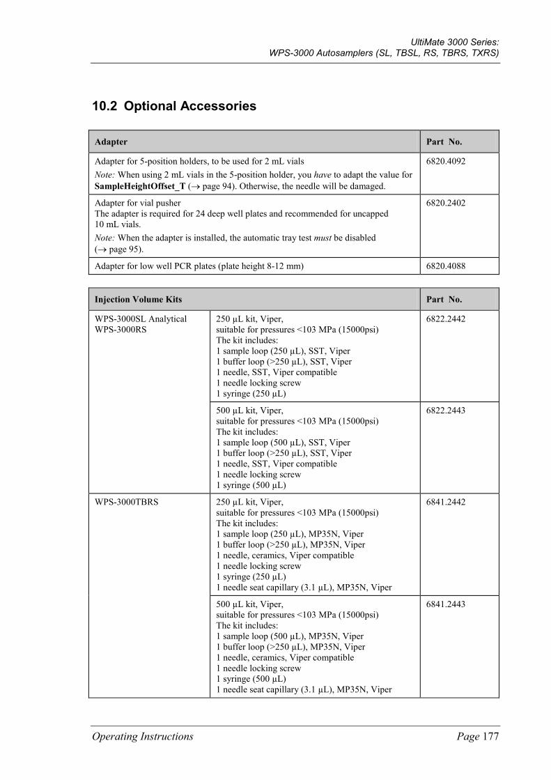
UltiMate 3000 Series: WPS-3000 Autosamplers (SL, TBSL, RS, TBRS, TXRS)
Operating Instructions Page 177
10.2 Optional Accessories
Adapter Part No.
Adapter for 5-position holders, to be used for 2 mL vials Note: When using 2 mL vials in the 5-position holder, you have to adapt the value for SampleHeightOffset_T (→ page 94). Otherwise, the needle will be damaged.
6820.4092
Adapter for vial pusher The adapter is required for 24 deep well plates and recommended for uncapped 10 mL vials. Note: When the adapter is installed, the automatic tray test must be disabled (→ page 95).
6820.2402
Adapter for low well PCR plates (plate height 8-12 mm) 6820.4088
Injection Volume Kits Part No.
WPS-3000SL Analytical WPS-3000RS
250 µL kit, Viper, suitable for pressures <103 MPa (15000psi) The kit includes: 1 sample loop (250 µL), SST, Viper 1 buffer loop (>250 µL), SST, Viper 1 needle, SST, Viper compatible 1 needle locking screw 1 syringe (250 µL)
6822.2442
500 µL kit, Viper, suitable for pressures <103 MPa (15000psi) The kit includes: 1 sample loop (500 µL), SST, Viper 1 buffer loop (>250 µL), SST, Viper 1 needle, SST, Viper compatible 1 needle locking screw 1 syringe (500 µL)
6822.2443
WPS-3000TBRS
250 µL kit, Viper, suitable for pressures <103 MPa (15000psi) The kit includes: 1 sample loop (250 µL), MP35N, Viper 1 buffer loop (>250 µL), MP35N, Viper 1 needle, ceramics, Viper compatible 1 needle locking screw 1 syringe (250 µL) 1 needle seat capillary (3.1 µL), MP35N, Viper
6841.2442
500 µL kit, Viper, suitable for pressures <103 MPa (15000psi) The kit includes: 1 sample loop (500 µL), MP35N, Viper 1 buffer loop (>250 µL), MP35N, Viper 1 needle, ceramics, Viper compatible 1 needle locking screw 1 syringe (500 µL) 1 needle seat capillary (3.1 µL), MP35N, Viper
6841.2443
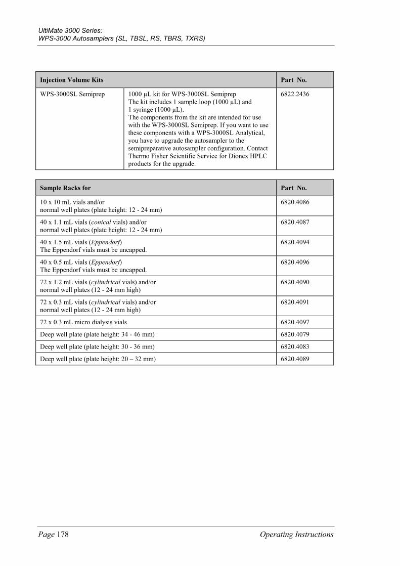
UltiMate 3000 Series: WPS-3000 Autosamplers (SL, TBSL, RS, TBRS, TXRS)
Page 178 Operating Instructions
Injection Volume Kits Part No.
WPS-3000SL Semiprep 1000 µL kit for WPS-3000SL Semiprep The kit includes 1 sample loop (1000 µL) and 1 syringe (1000 µL). The components from the kit are intended for use with the WPS-3000SL Semiprep. If you want to use these components with a WPS-3000SL Analytical, you have to upgrade the autosampler to the semipreparative autosampler configuration. Contact Thermo Fisher Scientific Service for Dionex HPLC products for the upgrade.
6822.2436
Sample Racks for Part No.
10 x 10 mL vials and/or normal well plates (plate height: 12 - 24 mm)
6820.4086
40 x 1.1 mL vials (conical vials) and/or normal well plates (plate height: 12 - 24 mm)
6820.4087
40 x 1.5 mL vials (Eppendorf) The Eppendorf vials must be uncapped.
6820.4094
40 x 0.5 mL vials (Eppendorf) The Eppendorf vials must be uncapped.
6820.4096
72 x 1.2 mL vials (cylindrical vials) and/or normal well plates (12 - 24 mm high)
6820.4090
72 x 0.3 mL vials (cylindrical vials) and/or normal well plates (12 - 24 mm high)
6820.4091
72 x 0.3 mL micro dialysis vials 6820.4097
Deep well plate (plate height: 34 - 46 mm) 6820.4079
Deep well plate (plate height: 30 - 36 mm) 6820.4083
Deep well plate (plate height: 20 – 32 mm) 6820.4089
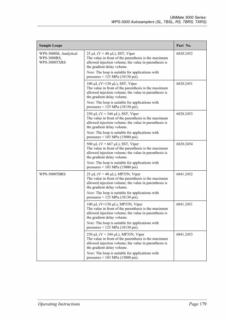
UltiMate 3000 Series: WPS-3000 Autosamplers (SL, TBSL, RS, TBRS, TXRS)
Operating Instructions Page 179
Sample Loops Part No.
WPS-3000SL Analytical WPS-3000RS, WPS-3000TXRS
25 µL (V = 40 µL), SST, Viper The value in front of the parenthesis is the maximum allowed injection volume; the value in parenthesis is the gradient delay volume. Note: The loop is suitable for applications with pressures < 125 MPa (18130 psi).
6820.2452
100 µL (V=130 µL), SST, Viper The value in front of the parenthesis is the maximum allowed injection volume; the value in parenthesis is the gradient delay volume. Note: The loop is suitable for applications with pressures < 125 MPa (18130 psi).
6820.2451
250 µL (V = 344 µL), SST, Viper The value in front of the parenthesis is the maximum allowed injection volume; the value in parenthesis is the gradient delay volume. Note: The loop is suitable for applications with pressures < 103 MPa (15000 psi).
6820.2453
500 µL (V = 667 µL), SST, Viper The value in front of the parenthesis is the maximum allowed injection volume; the value in parenthesis is the gradient delay volume. Note: The loop is suitable for applications with pressures < 103 MPa (15000 psi).
6820.2454
WPS-3000TBRS 25 µL (V = 40 µL), MP35N, Viper The value in front of the parenthesis is the maximum allowed injection volume; the value in parenthesis is the gradient delay volume. Note: The loop is suitable for applications with pressures < 125 MPa (18130 psi).
6841.2452
100 µL (V=130 µL), MP35N, Viper The value in front of the parenthesis is the maximum allowed injection volume; the value in parenthesis is the gradient delay volume. Note: The loop is suitable for applications with pressures < 125 MPa (18130 psi).
6841.2451
250 µL (V = 344 µL), MP35N, Viper The value in front of the parenthesis is the maximum allowed injection volume; the value in parenthesis is the gradient delay volume. Note: The loop is suitable for applications with pressures < 103 MPa (15000 psi).
6841.2453
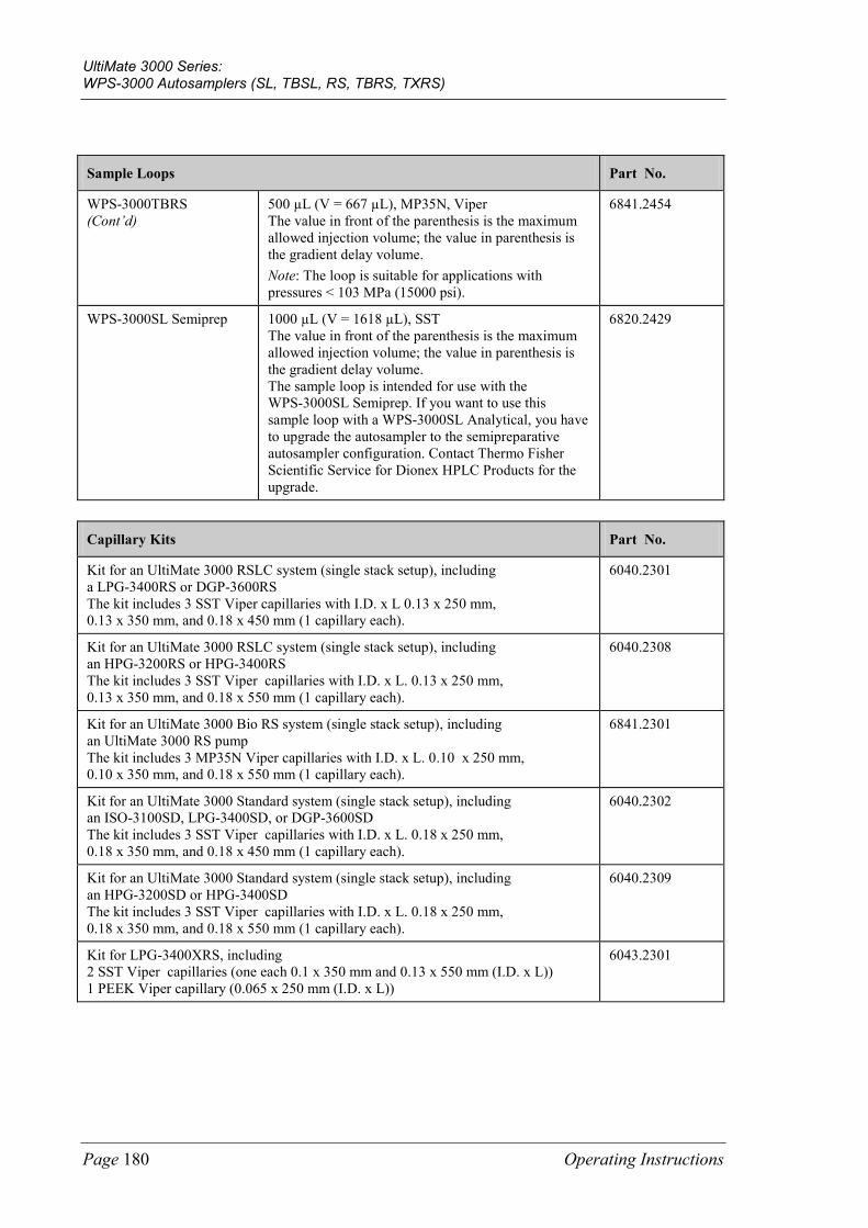
UltiMate 3000 Series: WPS-3000 Autosamplers (SL, TBSL, RS, TBRS, TXRS)
Page 180 Operating Instructions
Sample Loops Part No.
WPS-3000TBRS (Cont’d)
500 µL (V = 667 µL), MP35N, Viper The value in front of the parenthesis is the maximum allowed injection volume; the value in parenthesis is the gradient delay volume. Note: The loop is suitable for applications with pressures < 103 MPa (15000 psi).
6841.2454
WPS-3000SL Semiprep 1000 µL (V = 1618 µL), SST The value in front of the parenthesis is the maximum allowed injection volume; the value in parenthesis is the gradient delay volume. The sample loop is intended for use with the WPS-3000SL Semiprep. If you want to use this sample loop with a WPS-3000SL Analytical, you have to upgrade the autosampler to the semipreparative autosampler configuration. Contact Thermo Fisher Scientific Service for Dionex HPLC Products for the upgrade.
6820.2429
Capillary Kits Part No.
Kit for an UltiMate 3000 RSLC system (single stack setup), including a LPG-3400RS or DGP-3600RS The kit includes 3 SST Viper capillaries with I.D. x L 0.13 x 250 mm, 0.13 x 350 mm, and 0.18 x 450 mm (1 capillary each).
6040.2301
Kit for an UltiMate 3000 RSLC system (single stack setup), including an HPG-3200RS or HPG-3400RS The kit includes 3 SST Viper capillaries with I.D. x L. 0.13 x 250 mm, 0.13 x 350 mm, and 0.18 x 550 mm (1 capillary each).
6040.2308
Kit for an UltiMate 3000 Bio RS system (single stack setup), including an UltiMate 3000 RS pump The kit includes 3 MP35N Viper capillaries with I.D. x L. 0.10 x 250 mm, 0.10 x 350 mm, and 0.18 x 550 mm (1 capillary each).
6841.2301
Kit for an UltiMate 3000 Standard system (single stack setup), including an ISO-3100SD, LPG-3400SD, or DGP-3600SD The kit includes 3 SST Viper capillaries with I.D. x L. 0.18 x 250 mm, 0.18 x 350 mm, and 0.18 x 450 mm (1 capillary each).
6040.2302
Kit for an UltiMate 3000 Standard system (single stack setup), including an HPG-3200SD or HPG-3400SD The kit includes 3 SST Viper capillaries with I.D. x L. 0.18 x 250 mm, 0.18 x 350 mm, and 0.18 x 550 mm (1 capillary each).
6040.2309
Kit for LPG-3400XRS, including 2 SST Viper capillaries (one each 0.1 x 350 mm and 0.13 x 550 mm (I.D. x L)) 1 PEEK Viper capillary (0.065 x 250 mm (I.D. x L))
6043.2301
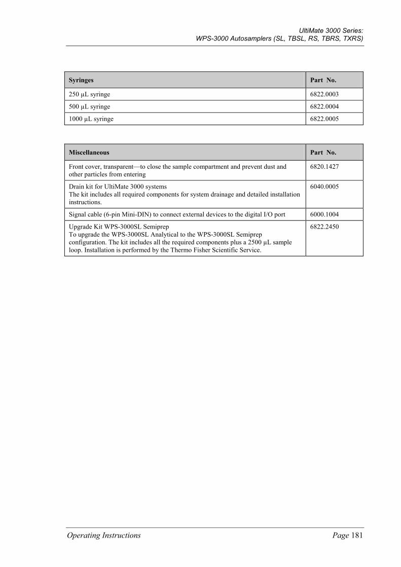
UltiMate 3000 Series: WPS-3000 Autosamplers (SL, TBSL, RS, TBRS, TXRS)
Operating Instructions Page 181
Syringes Part No.
250 µL syringe 6822.0003
500 µL syringe 6822.0004
1000 µL syringe 6822.0005
Miscellaneous Part No.
Front cover, transparent—to close the sample compartment and prevent dust and other particles from entering
6820.1427
Drain kit for UltiMate 3000 systems The kit includes all required components for system drainage and detailed installation instructions.
6040.0005
Signal cable (6-pin Mini-DIN) to connect external devices to the digital I/O port 6000.1004
Upgrade Kit WPS-3000SL Semiprep To upgrade the WPS-3000SL Analytical to the WPS-3000SL Semiprep configuration. The kit includes all the required components plus a 2500 µL sample loop. Installation is performed by the Thermo Fisher Scientific Service.
6822.2450
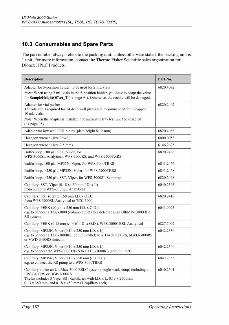
UltiMate 3000 Series: WPS-3000 Autosamplers (SL, TBSL, RS, TBRS, TXRS)
Page 182 Operating Instructions
10.3 Consumables and Spare Parts
The part number always refers to the packing unit. Unless otherwise stated, the packing unit is 1 unit. For more information, contact the Thermo Fisher Scientific sales organization for Dionex HPLC Products.
Description Part No.
Adapter for 5-position holder, to be used for 2 mL vials Note: When using 2 mL vials in the 5-position holder, you have to adapt the value for SampleHeightOffset_T (→ page 94). Otherwise, the needle will be damaged.
6820.4092
Adapter for vial pusher The adapter is required for 24 deep well plates and recommended for uncapped 10 mL vials. Note: When the adapter is installed, the automatic tray test must be disabled (→ page 95).
6820.2402
Adapter for low well PCR plates (plate height 8-12 mm) 6820.4088
Hexagon wrench (size 9/64" ) 6000.0053
Hexagon wrench (size 2.5 mm) 6146.2625
Buffer loop, 100 µL, SST, Viper, for WPS-3000SL Analytical, WPS-3000RS, and WPS-3000TXRS
6820.2466
Buffer loop, 100 µL, MP35N, Viper, for WPS-3000TBRS 6841.2466
Buffer loop, >250 µL, MP35N, Viper, for WPS-3000TBRS 6841.2468
Buffer loop, >250 µL, SST, Viper, for WPS-3000SL Semiprep 6820.2468
Capillary, SST, Viper (0.18 x 450 mm I.D. x L) from pump to WPS-3000SL Analytical
6040.2365
Capillary, SST (0.25 x 1.58 mm I.D. x O.D.) from WPS-3000SL Analytical to TCC-3000
6820.2418
Capillary, PEEK (90 µm x 250 mm I.D. x O.D.) e.g. to connect a TCC-3000 (column outlet) to a detector in an UltiMate 3000 Bio RS system
6041.9025
Capillary, PEEK (0.18 mm x 1/16" I.D. x O.D.), WPS-3000TBSL Analytical 6827.5002
Capillary, MP35N, Viper (0.10 x 250 mm I.D. x L) e.g. to connect a TCC-3000RS (column outlet) to a DAD-3000RS, MWD-3000RS or VWD-3400RS detector
6042.2330
Capillary, MP35N, Viper (0.10 x 350 mm I.D. x L) e.g. to connect the WPS-3000TBRS to a TCC-3000RS (column inlet)
6042.2340
Capillary, MP35N, Viper (0.18 x 550 mm (I.D. x L) e.g. to connect the RS pump to a WPS-3000TBRS
6042.2355
Capillary kit for an UltiMate 3000 RSLC system (single stack setup) including a LPG-3400RS or DGP-3600RS The kit includes 3 Viper SST capillaries with I.D. x L. 0.13 x 250 mm, 0.13 x 350 mm, and 0.18 x 450 mm (1 capillary each).
6040.2301
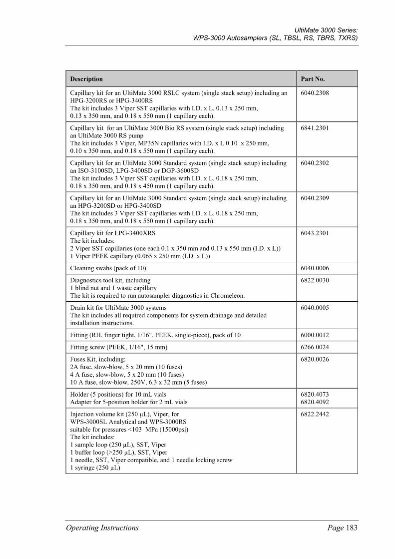
UltiMate 3000 Series: WPS-3000 Autosamplers (SL, TBSL, RS, TBRS, TXRS)
Operating Instructions Page 183
Description Part No.
Capillary kit for an UltiMate 3000 RSLC system (single stack setup) including an HPG-3200RS or HPG-3400RS The kit includes 3 Viper SST capillaries with I.D. x L. 0.13 x 250 mm, 0.13 x 350 mm, and 0.18 x 550 mm (1 capillary each).
6040.2308
Capillary kit for an UltiMate 3000 Bio RS system (single stack setup) including an UltiMate 3000 RS pump The kit includes 3 Viper, MP35N capillaries with I.D. x L 0.10 x 250 mm, 0.10 x 350 mm, and 0.18 x 550 mm (1 capillary each).
6841.2301
Capillary kit for an UltiMate 3000 Standard system (single stack setup) including an ISO-3100SD, LPG-3400SD or DGP-3600SD The kit includes 3 Viper SST capillaries with I.D. x L. 0.18 x 250 mm, 0.18 x 350 mm, and 0.18 x 450 mm (1 capillary each).
6040.2302
Capillary kit for an UltiMate 3000 Standard system (single stack setup) including an HPG-3200SD or HPG-3400SD The kit includes 3 Viper SST capillaries with I.D. x L. 0.18 x 250 mm, 0.18 x 350 mm, and 0.18 x 550 mm (1 capillary each).
6040.2309
Capillary kit for LPG-3400XRS The kit includes: 2 Viper SST capillaries (one each 0.1 x 350 mm and 0.13 x 550 mm (I.D. x L)) 1 Viper PEEK capillary (0.065 x 250 mm (I.D. x L))
6043.2301
Cleaning swabs (pack of 10) 6040.0006
Diagnostics tool kit, including 1 blind nut and 1 waste capillary The kit is required to run autosampler diagnostics in Chromeleon.
6822.0030
Drain kit for UltiMate 3000 systems The kit includes all required components for system drainage and detailed installation instructions.
6040.0005
Fitting (RH, finger tight, 1/16", PEEK, single-piece), pack of 10 6000.0012
Fitting screw (PEEK, 1/16", 15 mm) 6266.0024
Fuses Kit, including: 2A fuse, slow-blow, 5 x 20 mm (10 fuses) 4 A fuse, slow-blow, 5 x 20 mm (10 fuses) 10 A fuse, slow-blow, 250V, 6.3 x 32 mm (5 fuses)
6820.0026
Holder (5 positions) for 10 mL vials Adapter for 5-position holder for 2 mL vials
6820.4073 6820.4092
Injection volume kit (250 µL), Viper, for WPS-3000SL Analytical and WPS-3000RS suitable for pressures <103 MPa (15000psi) The kit includes: 1 sample loop (250 µL), SST, Viper 1 buffer loop (>250 µL), SST, Viper 1 needle, SST, Viper compatible, and 1 needle locking screw 1 syringe (250 µL)
6822.2442
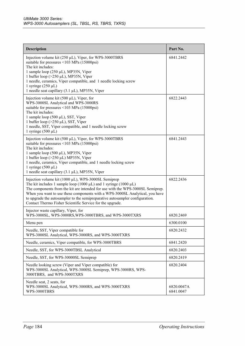
UltiMate 3000 Series: WPS-3000 Autosamplers (SL, TBSL, RS, TBRS, TXRS)
Page 184 Operating Instructions
Description Part No.
Injection volume kit (250 µL), Viper, for WPS-3000TBRS suitable for pressures <103 MPa (15000psi) The kit includes: 1 sample loop (250 µL), MP35N, Viper 1 buffer loop (>250 µL), MP35N, Viper 1 needle, ceramics, Viper compatible, and 1 needle locking screw 1 syringe (250 µL) 1 needle seat capillary (3.1 µL), MP35N, Viper
6841.2442
Injection volume kit (500 µL), Viper, for WPS-3000SL Analytical and WPS-3000RS suitable for pressures <103 MPa (15000psi) The kit includes: 1 sample loop (500 µL), SST, Viper 1 buffer loop (>250 µL), SST, Viper 1 needle, SST, Viper compatible, and 1 needle locking screw 1 syringe (500 µL)
6822.2443
Injection volume kit (500 µL), Viper, for WPS-3000TBRS suitable for pressures <103 MPa (15000psi) The kit includes: 1 sample loop (500 µL), MP35N, Viper 1 buffer loop (>250 µL) MP35N, Viper 1 needle, ceramics, Viper compatible, and 1 needle locking screw 1 syringe (500 µL) 1 needle seat capillary (3.1 µL), MP35N, Viper
6841.2443
Injection volume kit (1000 µL), WPS-3000SL Semiprep The kit includes 1 sample loop (1000 µL) and 1 syringe (1000 µL) The components from the kit are intended for use with the WPS-3000SL Semiprep. When you want to use these components with a WPS-3000SL Analytical, you have to upgrade the autosampler to the semipreparative autosampler configuration. Contact Thermo Fisher Scientific Service for the upgrade.
6822.2436
Injector waste capillary, Viper, for WPS-3000SL, WPS-3000RS,WPS-3000TBRS, and WPS-3000TXRS
6820.2469
Menu pen 6300.0100
Needle, SST, Viper compatible for WPS-3000SL Analytical, WPS-3000RS, and WPS-3000TXRS
6820.2432
Needle, ceramics, Viper compatible, for WPS-3000TBRS 6841.2420
Needle, SST, for WPS-3000TBSL Analytical 6820.2403
Needle, SST, for WPS-30000SL Semiprep 6820.2419
Needle looking screw (Viper and Viper compatible) for WPS-3000SL Analytical, WPS-3000SL Semiprep, WPS-3000RS, WPS-3000TBRS, and WPS-3000TXRS
6820.2404
Needle seat, 2 seats, for WPS-3000SL Analytical, WPS-3000RS, and WPS-3000TXRS WPS-3000TBRS
6820.0047A 6841.0047
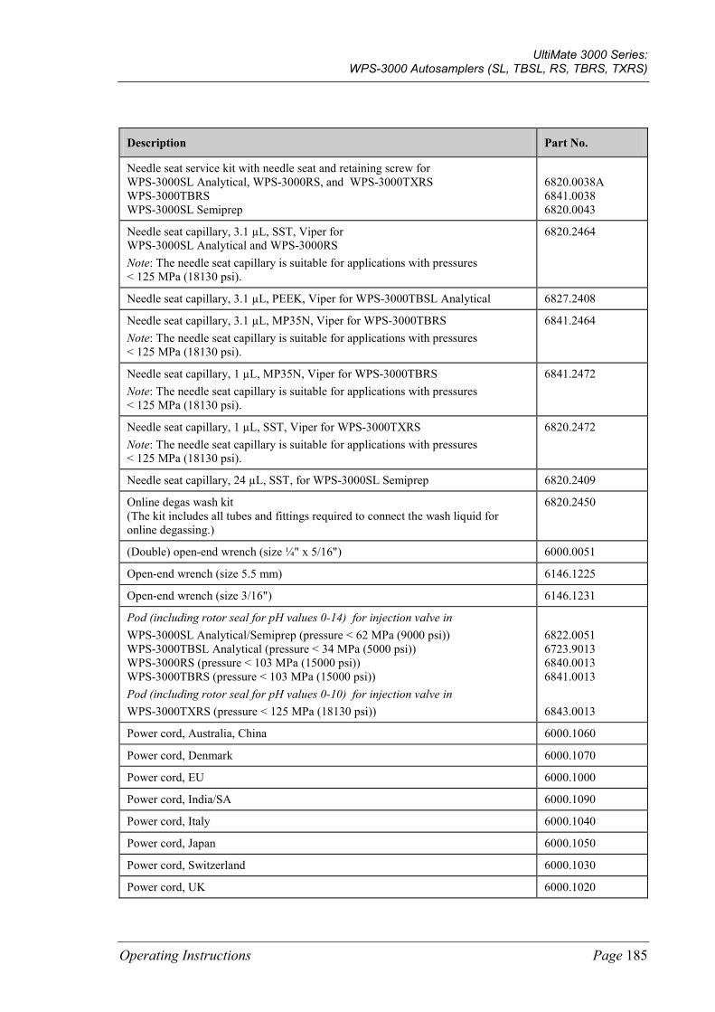
UltiMate 3000 Series: WPS-3000 Autosamplers (SL, TBSL, RS, TBRS, TXRS)
Operating Instructions Page 185
Description Part No.
Needle seat service kit with needle seat and retaining screw for WPS-3000SL Analytical, WPS-3000RS, and WPS-3000TXRS WPS-3000TBRS WPS-3000SL Semiprep
6820.0038A 6841.0038 6820.0043
Needle seat capillary, 3.1 µL, SST, Viper for WPS-3000SL Analytical and WPS-3000RS Note: The needle seat capillary is suitable for applications with pressures < 125 MPa (18130 psi).
6820.2464
Needle seat capillary, 3.1 µL, PEEK, Viper for WPS-3000TBSL Analytical 6827.2408
Needle seat capillary, 3.1 µL, MP35N, Viper for WPS-3000TBRS Note: The needle seat capillary is suitable for applications with pressures < 125 MPa (18130 psi).
6841.2464
Needle seat capillary, 1 µL, MP35N, Viper for WPS-3000TBRS Note: The needle seat capillary is suitable for applications with pressures < 125 MPa (18130 psi).
6841.2472
Needle seat capillary, 1 µL, SST, Viper for WPS-3000TXRS Note: The needle seat capillary is suitable for applications with pressures < 125 MPa (18130 psi).
6820.2472
Needle seat capillary, 24 µL, SST, for WPS-3000SL Semiprep 6820.2409
Online degas wash kit (The kit includes all tubes and fittings required to connect the wash liquid for online degassing.)
6820.2450
(Double) open-end wrench (size ¼" x 5/16") 6000.0051
Open-end wrench (size 5.5 mm) 6146.1225
Open-end wrench (size 3/16") 6146.1231
Pod (including rotor seal for pH values 0-14) for injection valve in WPS-3000SL Analytical/Semiprep (pressure < 62 MPa (9000 psi)) WPS-3000TBSL Analytical (pressure < 34 MPa (5000 psi)) WPS-3000RS (pressure < 103 MPa (15000 psi)) WPS-3000TBRS (pressure < 103 MPa (15000 psi)) Pod (including rotor seal for pH values 0-10) for injection valve in WPS-3000TXRS (pressure < 125 MPa (18130 psi))
6822.0051 6723.9013 6840.0013 6841.0013 6843.0013
Power cord, Australia, China 6000.1060
Power cord, Denmark 6000.1070
Power cord, EU 6000.1000
Power cord, India/SA 6000.1090
Power cord, Italy 6000.1040
Power cord, Japan 6000.1050
Power cord, Switzerland 6000.1030
Power cord, UK 6000.1020
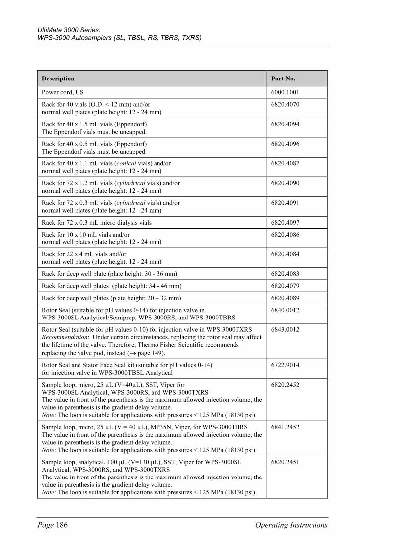
UltiMate 3000 Series: WPS-3000 Autosamplers (SL, TBSL, RS, TBRS, TXRS)
Page 186 Operating Instructions
Description Part No.
Power cord, US 6000.1001
Rack for 40 vials (O.D. < 12 mm) and/or normal well plates (plate height: 12 - 24 mm)
6820.4070
Rack for 40 x 1.5 mL vials (Eppendorf) The Eppendorf vials must be uncapped.
6820.4094
Rack for 40 x 0.5 mL vials (Eppendorf) The Eppendorf vials must be uncapped.
6820.4096
Rack for 40 x 1.1 mL vials (conical vials) and/or normal well plates (plate height: 12 - 24 mm)
6820.4087
Rack for 72 x 1.2 mL vials (cylindrical vials) and/or normal well plates (plate height: 12 - 24 mm)
6820.4090
Rack for 72 x 0.3 mL vials (cylindrical vials) and/or normal well plates (plate height: 12 - 24 mm)
6820.4091
Rack for 72 x 0.3 mL micro dialysis vials 6820.4097
Rack for 10 x 10 mL vials and/or normal well plates (plate height: 12 - 24 mm)
6820.4086
Rack for 22 x 4 mL vials and/or normal well plates (plate height: 12 - 24 mm)
6820.4084
Rack for deep well plate (plate height: 30 - 36 mm) 6820.4083
Rack for deep well plates (plate height: 34 - 46 mm) 6820.4079
Rack for deep well plates (plate height: 20 – 32 mm) 6820.4089
Rotor Seal (suitable for pH values 0-14) for injection valve in WPS-3000SL Analytical/Semiprep, WPS-3000RS, and WPS-3000TBRS
6840.0012
Rotor Seal (suitable for pH values 0-10) for injection valve in WPS-3000TXRS Recommendation: Under certain circumstances, replacing the rotor seal may affect the lifetime of the valve. Therefore, Thermo Fisher Scientific recommends replacing the valve pod, instead (→ page 149).
6843.0012
Rotor Seal and Stator Face Seal kit (suitable for pH values 0-14) for injection valve in WPS-3000TBSL Analytical
6722.9014
Sample loop, micro, 25 µL (V=40µL), SST, Viper for WPS-3000SL Analytical, WPS-3000RS, and WPS-3000TXRS The value in front of the parenthesis is the maximum allowed injection volume; the value in parenthesis is the gradient delay volume. Note: The loop is suitable for applications with pressures < 125 MPa (18130 psi).
6820.2452
Sample loop, micro, 25 µL (V = 40 µL), MP35N, Viper, for WPS-3000TBRS The value in front of the parenthesis is the maximum allowed injection volume; the value in parenthesis is the gradient delay volume. Note: The loop is suitable for applications with pressures < 125 MPa (18130 psi).
6841.2452
Sample loop, analytical, 100 µL (V=130 µL), SST, Viper for WPS-3000SL Analytical, WPS-3000RS, and WPS-3000TXRS The value in front of the parenthesis is the maximum allowed injection volume; the value in parenthesis is the gradient delay volume. Note: The loop is suitable for applications with pressures < 125 MPa (18130 psi).
6820.2451
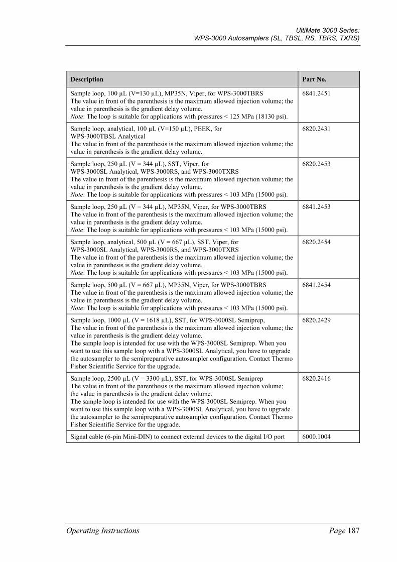
UltiMate 3000 Series: WPS-3000 Autosamplers (SL, TBSL, RS, TBRS, TXRS)
Operating Instructions Page 187
Description Part No.
Sample loop, 100 µL (V=130 µL), MP35N, Viper, for WPS-3000TBRS The value in front of the parenthesis is the maximum allowed injection volume; the value in parenthesis is the gradient delay volume. Note: The loop is suitable for applications with pressures < 125 MPa (18130 psi).
6841.2451
Sample loop, analytical, 100 µL (V=150 µL), PEEK, for WPS-3000TBSL Analytical The value in front of the parenthesis is the maximum allowed injection volume; the value in parenthesis is the gradient delay volume.
6820.2431
Sample loop, 250 µL (V = 344 µL), SST, Viper, for WPS-3000SL Analytical, WPS-3000RS, and WPS-3000TXRS The value in front of the parenthesis is the maximum allowed injection volume; the value in parenthesis is the gradient delay volume. Note: The loop is suitable for applications with pressures < 103 MPa (15000 psi).
6820.2453
Sample loop, 250 µL (V = 344 µL), MP35N, Viper, for WPS-3000TBRS The value in front of the parenthesis is the maximum allowed injection volume; the value in parenthesis is the gradient delay volume. Note: The loop is suitable for applications with pressures < 103 MPa (15000 psi).
6841.2453
Sample loop, analytical, 500 µL (V = 667 µL), SST, Viper, for WPS-3000SL Analytical, WPS-3000RS, and WPS-3000TXRS The value in front of the parenthesis is the maximum allowed injection volume; the value in parenthesis is the gradient delay volume. Note: The loop is suitable for applications with pressures < 103 MPa (15000 psi).
6820.2454
Sample loop, 500 µL (V = 667 µL), MP35N, Viper, for WPS-3000TBRS The value in front of the parenthesis is the maximum allowed injection volume; the value in parenthesis is the gradient delay volume. Note: The loop is suitable for applications with pressures < 103 MPa (15000 psi).
6841.2454
Sample loop, 1000 µL (V = 1618 µL), SST, for WPS-3000SL Semiprep, The value in front of the parenthesis is the maximum allowed injection volume; the value in parenthesis is the gradient delay volume. The sample loop is intended for use with the WPS-3000SL Semiprep. When you want to use this sample loop with a WPS-3000SL Analytical, you have to upgrade the autosampler to the semipreparative autosampler configuration. Contact Thermo Fisher Scientific Service for the upgrade.
6820.2429
Sample loop, 2500 µL (V = 3300 µL), SST, for WPS-3000SL Semiprep The value in front of the parenthesis is the maximum allowed injection volume; the value in parenthesis is the gradient delay volume. The sample loop is intended for use with the WPS-3000SL Semiprep. When you want to use this sample loop with a WPS-3000SL Analytical, you have to upgrade the autosampler to the semipreparative autosampler configuration. Contact Thermo Fisher Scientific Service for the upgrade.
6820.2416
Signal cable (6-pin Mini-DIN) to connect external devices to the digital I/O port 6000.1004
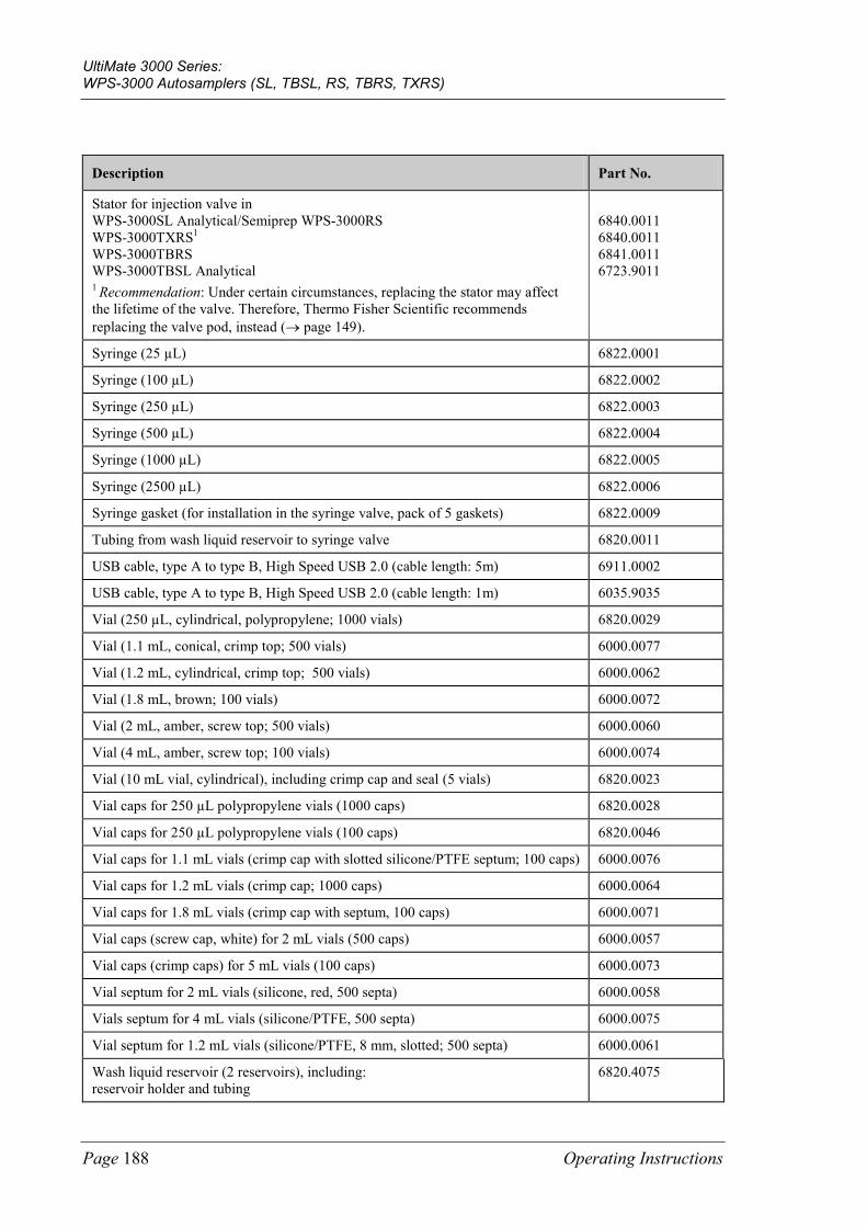
UltiMate 3000 Series: WPS-3000 Autosamplers (SL, TBSL, RS, TBRS, TXRS)
Page 188 Operating Instructions
Description Part No.
Stator for injection valve in WPS-3000SL Analytical/Semiprep WPS-3000RS WPS-3000TXRS1 WPS-3000TBRS WPS-3000TBSL Analytical 1 Recommendation: Under certain circumstances, replacing the stator may affect the lifetime of the valve. Therefore, Thermo Fisher Scientific recommends replacing the valve pod, instead (→ page 149).
6840.0011 6840.0011 6841.0011 6723.9011
Syringe (25 µL) 6822.0001
Syringe (100 µL) 6822.0002
Syringe (250 µL) 6822.0003
Syringe (500 µL) 6822.0004
Syringe (1000 µL) 6822.0005
Syringe (2500 µL) 6822.0006
Syringe gasket (for installation in the syringe valve, pack of 5 gaskets) 6822.0009
Tubing from wash liquid reservoir to syringe valve 6820.0011
USB cable, type A to type B, High Speed USB 2.0 (cable length: 5m) 6911.0002
USB cable, type A to type B, High Speed USB 2.0 (cable length: 1m) 6035.9035
Vial (250 µL, cylindrical, polypropylene; 1000 vials) 6820.0029
Vial (1.1 mL, conical, crimp top; 500 vials) 6000.0077
Vial (1.2 mL, cylindrical, crimp top; 500 vials) 6000.0062
Vial (1.8 mL, brown; 100 vials) 6000.0072
Vial (2 mL, amber, screw top; 500 vials) 6000.0060
Vial (4 mL, amber, screw top; 100 vials) 6000.0074
Vial (10 mL vial, cylindrical), including crimp cap and seal (5 vials) 6820.0023
Vial caps for 250 µL polypropylene vials (1000 caps) 6820.0028
Vial caps for 250 µL polypropylene vials (100 caps) 6820.0046
Vial caps for 1.1 mL vials (crimp cap with slotted silicone/PTFE septum; 100 caps) 6000.0076
Vial caps for 1.2 mL vials (crimp cap; 1000 caps) 6000.0064
Vial caps for 1.8 mL vials (crimp cap with septum, 100 caps) 6000.0071
Vial caps (screw cap, white) for 2 mL vials (500 caps) 6000.0057
Vial caps (crimp caps) for 5 mL vials (100 caps) 6000.0073
Vial septum for 2 mL vials (silicone, red, 500 septa) 6000.0058
Vials septum for 4 mL vials (silicone/PTFE, 500 septa) 6000.0075
Vial septum for 1.2 mL vials (silicone/PTFE, 8 mm, slotted; 500 septa) 6000.0061
Wash liquid reservoir (2 reservoirs), including: reservoir holder and tubing
6820.4075
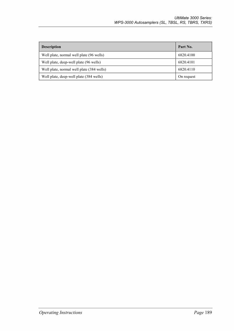
UltiMate 3000 Series: WPS-3000 Autosamplers (SL, TBSL, RS, TBRS, TXRS)
Operating Instructions Page 189
Description Part No.
Well plate, normal well plate (96 wells) 6820.4100
Well plate, deep-well plate (96 wells) 6820.4101
Well plate, normal well plate (384 wells) 6820.4110
Well plate, deep-well plate (384 wells) On request

UltiMate 3000 Series: WPS-3000 Autosamplers (SL, TBSL, RS, TBRS, TXRS)
Page 190 Operating Instructions
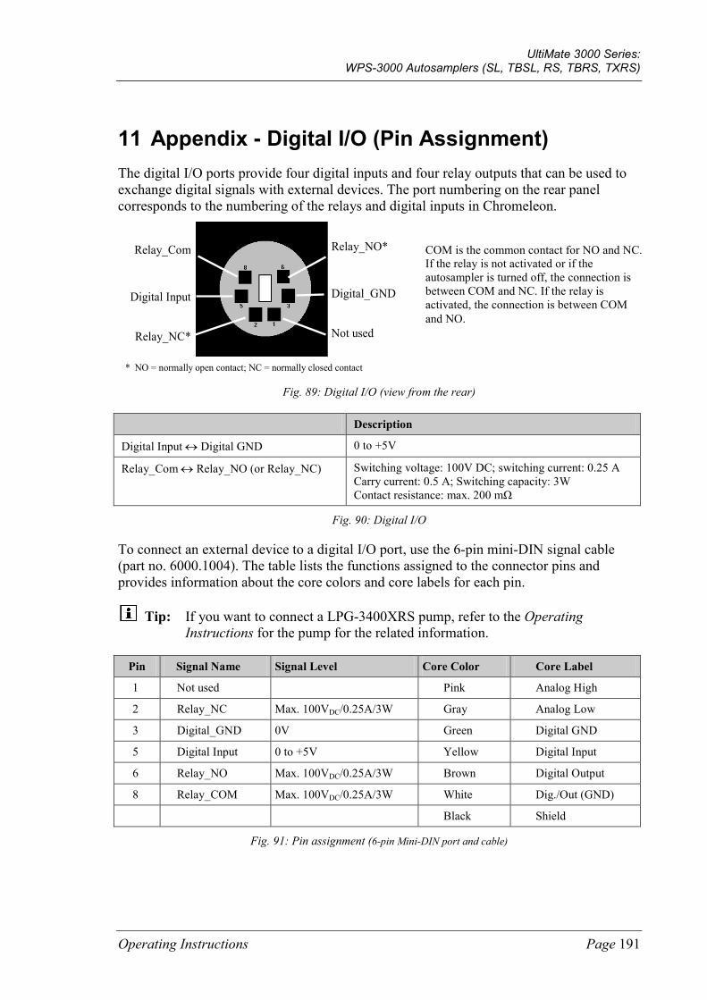
UltiMate 3000 Series: WPS-3000 Autosamplers (SL, TBSL, RS, TBRS, TXRS)
Operating Instructions Page 191
11 Appendix - Digital I/O (Pin Assignment) The digital I/O ports provide four digital inputs and four relay outputs that can be used to exchange digital signals with external devices. The port numbering on the rear panel corresponds to the numbering of the relays and digital inputs in Chromeleon.
* NO = normally open contact; NC = normally closed contact
Relay_NO*
Digital_GND
Not used
Relay_Com
Digital Input
Relay_NC*
Fig. 89: Digital I/O (view from the rear)
Description
Digital Input ↔ Digital GND 0 to +5V
Relay_Com ↔ Relay_NO (or Relay_NC) Switching voltage: 100V DC; switching current: 0.25 A Carry current: 0.5 A; Switching capacity: 3W Contact resistance: max. 200 mΩ
Fig. 90: Digital I/O
To connect an external device to a digital I/O port, use the 6-pin mini-DIN signal cable (part no. 6000.1004). The table lists the functions assigned to the connector pins and provides information about the core colors and core labels for each pin.
Tip: If you want to connect a LPG-3400XRS pump, refer to the Operating Instructions for the pump for the related information.
Pin Signal Name Signal Level Core Color Core Label
1 Not used Pink Analog High
2 Relay_NC Max. 100VDC/0.25A/3W Gray Analog Low
3 Digital_GND 0V Green Digital GND
5 Digital Input 0 to +5V Yellow Digital Input
6 Relay_NO Max. 100VDC/0.25A/3W Brown Digital Output
8 Relay_COM Max. 100VDC/0.25A/3W White Dig./Out (GND)
Black Shield
Fig. 91: Pin assignment (6-pin Mini-DIN port and cable)
COM is the common contact for NO and NC. If the relay is not activated or if the autosampler is turned off, the connection is between COM and NC. If the relay is activated, the connection is between COM and NO.

UltiMate 3000 Series: WPS-3000 Autosamplers (SL, TBSL, RS, TBRS, TXRS)
Page 192 Operating Instructions
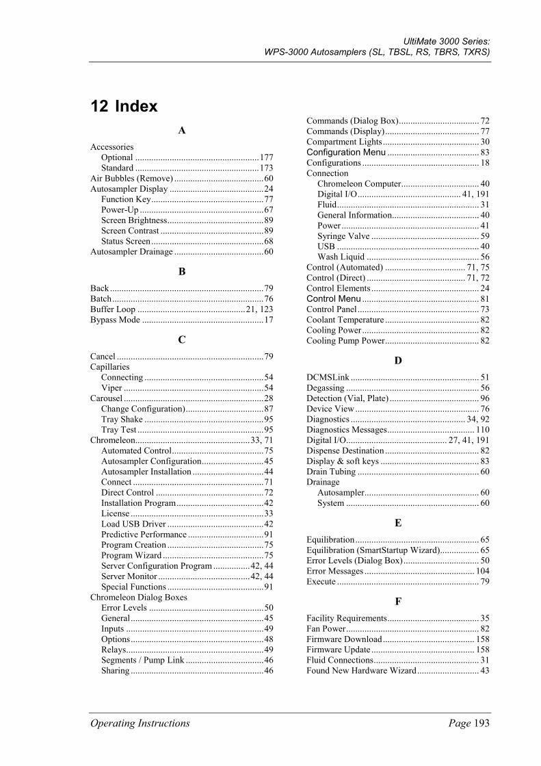
UltiMate 3000 Series: WPS-3000 Autosamplers (SL, TBSL, RS, TBRS, TXRS)
Operating Instructions Page 193
12 Index A
Accessories Optional ...................................................... 177 Standard ...................................................... 173
Air Bubbles (Remove) ....................................... 60 Autosampler Display ......................................... 24
Function Key ................................................. 77 Power-Up ...................................................... 67 Screen Brightness .......................................... 89 Screen Contrast ............................................. 89 Status Screen ................................................. 68
Autosampler Drainage ....................................... 60
B Back ................................................................... 79 Batch .................................................................. 76 Buffer Loop ............................................... 21, 123 Bypass Mode ..................................................... 17
C Cancel ................................................................ 79 Capillaries
Connecting .................................................... 54 Viper ............................................................. 54
Carousel ............................................................. 28 Change Configuration) .................................. 87 Tray Shake .................................................... 95 Tray Test ....................................................... 95
Chromeleon.................................................. 33, 71 Automated Control ........................................ 75 Autosampler Configuration ........................... 45 Autosampler Installation ............................... 44 Connect ......................................................... 71 Direct Control ............................................... 72 Installation Program ...................................... 42 License .......................................................... 33 Load USB Driver .......................................... 42 Predictive Performance ................................. 91 Program Creation .......................................... 75 Program Wizard ............................................ 75 Server Configuration Program ................ 42, 44 Server Monitor ........................................ 42, 44 Special Functions .......................................... 91
Chromeleon Dialog Boxes Error Levels .................................................. 50 General .......................................................... 45 Inputs ............................................................ 49 Options .......................................................... 48 Relays ............................................................ 49 Segments / Pump Link .................................. 46 Sharing .......................................................... 46
Commands (Dialog Box) ................................... 72 Commands (Display) ......................................... 77 Compartment Lights .......................................... 30 Configuration Menu ........................................ 83 Configurations ................................................... 18 Connection
Chromeleon Computer .................................. 40 Digital I/O ............................................. 41, 191 Fluid .............................................................. 31 General Information...................................... 40 Power ............................................................ 41 Syringe Valve ............................................... 59 USB .............................................................. 40 Wash Liquid ................................................. 56
Control (Automated) ................................... 71, 75 Control (Direct) ........................................... 71, 72 Control Elements ............................................... 24 Control Menu ................................................... 81 Control Panel ..................................................... 73 Coolant Temperature ......................................... 82 Cooling Power ................................................... 82 Cooling Pump Power ......................................... 82
D DCMSLink ........................................................ 51 Degassing .......................................................... 56 Detection (Vial, Plate) ....................................... 96 Device View ...................................................... 76 Diagnostics .................................................. 34, 92 Diagnostics Messages ...................................... 110 Digital I/O............................................ 27, 41, 191 Dispense Destination ......................................... 82 Display & soft keys ........................................... 83 Drain Tubing ..................................................... 60 Drainage
Autosampler .................................................. 60 System .......................................................... 60
E Equilibration ...................................................... 65 Equilibration (SmartStartup Wizard) ................. 65 Error Levels (Dialog Box) ................................. 50 Error Messages ................................................ 104 Execute .............................................................. 79
F Facility Requirements ........................................ 35 Fan Power .......................................................... 82 Firmware Download ........................................ 158 Firmware Update ............................................. 158 Fluid Connections .............................................. 31 Found New Hardware Wizard ........................... 43
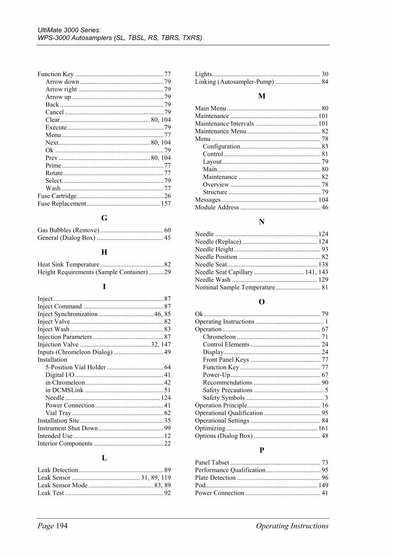
UltiMate 3000 Series: WPS-3000 Autosamplers (SL, TBSL, RS, TBRS, TXRS)
Page 194 Operating Instructions
Function Key ..................................................... 77 Arrow down .................................................. 79 Arrow right ................................................... 79 Arrow up ....................................................... 79 Back .............................................................. 79 Cancel ........................................................... 79 Clear ...................................................... 80, 104 Execute.......................................................... 79 Menu ............................................................. 77 Next ....................................................... 80, 104 Ok ................................................................. 79 Prev ....................................................... 80, 104 Prime ............................................................. 77 Rotate ............................................................ 77 Select ............................................................. 79 Wash ............................................................. 77
Fuse Cartridge .................................................... 26 Fuse Replacement ............................................ 157
G Gas Bubbles (Remove) ...................................... 60 General (Dialog Box) ........................................ 45
H Heat Sink Temperature ...................................... 82 Height Requirements (Sample Container) ......... 29
I Inject .................................................................. 87 Inject Command ................................................ 87 Inject Synchronization ................................. 46, 85 Inject Valve........................................................ 82 Inject Wash ........................................................ 83 Injection Parameters .......................................... 87 Injection Valve .......................................... 32, 147 Inputs (Chromeleon Dialog) .............................. 49 Installation
5-Position Vial Holder .................................. 64 Digital I/O ..................................................... 41 in Chromeleon ............................................... 42 in DCMSLink ............................................... 51 Needle ......................................................... 124 Power Connection ......................................... 41 Vial Tray ....................................................... 62
Installation Site .................................................. 35 Instrument Shut Down ....................................... 99 Intended Use ...................................................... 12 Interior Components .......................................... 22
L Leak Detection ................................................... 89 Leak Sensor ......................................... 31, 89, 119 Leak Sensor Mode ....................................... 83, 89 Leak Test ........................................................... 92
Lights ................................................................. 30 Linking (Autosampler-Pump) ........................... 84
M Main Menu ........................................................ 80 Maintenance .................................................... 101 Maintenance Intervals ..................................... 101 Maintenance Menu ............................................ 82 Menu ................................................................. 78
Configuration ................................................ 83 Control .......................................................... 81 Layout ........................................................... 79 Main .............................................................. 80 Maintenance ................................................. 82 Overview ...................................................... 78 Structure ....................................................... 79
Messages ......................................................... 104 Module Address ................................................ 46
N Needle ............................................................. 124 Needle (Replace) ............................................. 124 Needle Height .................................................... 93 Needle Position ................................................. 82 Needle Seat ...................................................... 138 Needle Seat Capillary .............................. 141, 143 Needle Wash ................................................... 129 Nominal Sample Temperature ........................... 81
O Ok ...................................................................... 79 Operating Instructions ......................................... 1 Operation ........................................................... 67
Chromeleon .................................................. 71 Control Elements .......................................... 24 Display .......................................................... 24 Front Panel Keys .......................................... 77 Function Key ................................................ 77 Power-Up ...................................................... 67 Recommendations ........................................ 90 Safety Precautions .......................................... 5 Safety Symbols ............................................... 3
Operation Principle............................................ 16 Operational Qualification .................................. 95 Operational Settings .......................................... 84 Optimizing ....................................................... 161 Options (Dialog Box) ........................................ 48
P Panel Tabset ...................................................... 73 Performance Qualification................................. 95 Plate Detection .................................................. 96 Pod................................................................... 149 Power Connection ............................................. 41
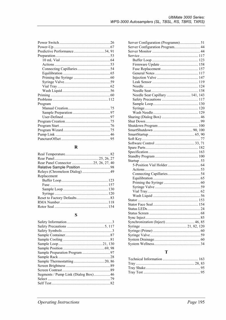
UltiMate 3000 Series: WPS-3000 Autosamplers (SL, TBSL, RS, TBRS, TXRS)
Operating Instructions Page 195
Power Switch ..................................................... 26 Power-Up ........................................................... 67 Predictive Performance ................................ 34, 91 Preparation ......................................................... 53
10 mL Vial .................................................... 64 Actions .......................................................... 53 Connecting Capillaries .................................. 54 Equilibration ................................................. 65 Priming the Syringe ...................................... 60 Syringe Valve ................................................ 59 Vial Tray ....................................................... 62 Wash Liquid .................................................. 56
Priming .............................................................. 60 Problems .......................................................... 112 Program
Manual Creation ............................................ 75 Sample Preparation ....................................... 97 User-Defined ................................................. 97
Program Creation ............................................... 75 Program Start ..................................................... 76 Program Wizard ................................................. 75 Pump Link ......................................................... 46 PunctureOffset ................................................... 95
R Real Temperature ............................................... 82 Rear Panel .............................................. 25, 26, 27 Rear Panel Connector ...................... 25, 26, 27, 40 Relative Sample Position ............................... 98 Relays (Chromeleon Dialog) ............................. 49 Replacement
Buffer Loop ................................................. 123 Fuse ............................................................. 157 Sample Loop ............................................... 130 Syringe ........................................................ 120
Reset to Factory Defaults ................................... 83 RMA Number .................................................. 118 Rotor Seal ........................................................ 154
S Safety Information ............................................... 3 Safety Precautions ....................................... 5, 117 Safety Symbols .................................................... 3 Sample Container ............................................... 87 Sample Cooling ................................................. 81 Sample Loop .............................................. 21, 130 Sample Position ........................................... 69, 98 Sample Preparation Program ............................. 97 Sample Rack ...................................................... 28 Sample Thermostatting ................................ 20, 86 Screen Brightness .............................................. 89 Screen Contrast .................................................. 89 Segments / Pump Link (Dialog Box) ................. 46 Select ................................................................. 79 Self Test ............................................................. 82
Server Configuration (Programm) ..................... 51 Server Configuration Program........................... 44 Server Monitor .................................................. 44 Service ............................................................. 117
Buffer Loop ................................................ 123 Firmware Update ........................................ 158 Fuse Replacement ....................................... 157 General Notes ............................................. 117 Injection Valve ........................................... 147 Leak Sensor ................................................ 119 Needle ......................................................... 124 Needle Seat ................................................. 138 Needle Seat Capillary ......................... 141, 143 Safety Precautions ...................................... 117 Sample Loop ............................................... 130 Syringe ........................................................ 120 Wash Needle ............................................... 129
Sharing (Dialog Box) ........................................ 46 Shut Down ......................................................... 99 Shutdown Program .......................................... 100 SmartShutdown ......................................... 90, 100 SmartStartup ................................................ 65, 90 Soft Key ............................................................. 77 Software Control ......................................... 33, 71 Spare Parts ....................................................... 182 Specification .................................................... 163 Standby Program ............................................. 100 Startup ............................................................... 53
5-Position Vial Holder .................................. 64 Actions .......................................................... 53 Connecting Capillaries .................................. 54 Equilibration ................................................. 65 Priming the Syringe ...................................... 60 Syringe Valve ............................................... 59 Vial Tray ....................................................... 62 Wash Liquid ................................................. 56
Stator ............................................................... 153 Stator Face Seal ............................................... 154 Status LEDs ....................................................... 24 Status Screen ..................................................... 68 Sync Inject ......................................................... 85 Synchronization (Inject) .............................. 46, 85 Syringe ................................................ 21, 82, 120 Syringe (Prime) ................................................. 60 Syringe Valve .................................................... 59 System Drainage ................................................ 60 System Wellness ................................................ 34
T Technical Information ..................................... 163 Tray ............................................................. 28, 83 Tray Shake ......................................................... 95 Tray Test ........................................................... 95
UltiMate 3000 Series: WPS-3000 Autosamplers (SL, TBSL, RS, TBRS, TXRS)
Page 196 Operating Instructions
Troubleshooting ............................................... 103 Diagnostics Messages ................................. 110 Error Messages ........................................... 104 Frequently Observed Problems ................... 112
U Unit Description ................................................ 15
Configurations .............................................. 18 Interior Components ..................................... 22 Overview ....................................................... 15 Principle of Operation ................................... 16 Sample Thermostatting Option ..................... 20
Unpacking .......................................................... 36 USB ............................................................. 26, 40 User Information ................................................ 13
V Version Info ....................................................... 82 Vial ........................................................ 28, 62, 64
Detection ....................................................... 96 Recommendation .......................................... 29 Venting.......................................................... 95
Vial Rack ........................................................... 28 Vial Tray ............................................................ 28
Install ............................................................ 62 Load .............................................................. 62
Viper Capillaries ................................................ 54
W Wash .......................................................... 81, 129 Wash Liquid ...................................................... 56 Well Plate .......................................................... 28
Detection ....................................................... 96 Install ............................................................ 62 Recommendation .......................................... 29