thermo-opto-mechanical analysis of a cubesat lens mount · thermo-opto-mechanical analysis of a...
TRANSCRIPT

Thermo-opto-mechanical analysis of a cubesat lens mount
James A. Champagne*a,b, James H. Burgeb, Blake G. Crowthera
aSpace Dynamics Laboratory, 1695 North Research Parkway, North Logan, UT, 84341; bCollege of Optical Sciences, University of Arizona, Tucson, AZ 85721;
ABSTRACT
A potential cubesat payload for low resolution study of planet Earth from space is an optical imaging system. Due to budget, space, and time constraints, commercial photographic lenses of the double Gauss type are prime candidates for limited duration cubesat optics. However, photographic objectives are not designed to operate in a space environment and modifications are usually necessary. One method of improving optical performance of the objective over large temperature variations is by replacing the stock lens mount with a different material. This paper describes the thermo-opto-mechanical analysis of several lens mount materials for a double Gauss imaging system suitable for a cubesat.
Keywords: cubesat, photographic lens, double Gauss, lens mount, defocus, thermal, Bahtinov
1. INTRODUCTION The miniaturization of satellites has advanced considerably in the past 25 years and it is now possible to build remote sensing systems based on the cubesat configuration. Cubesats are part of the nanosatellite class first developed by Stanford University and California Polytechnic State University in 1999 to give students satellite development experience1. A standard for cubesat design was created to aid in quick development time and university budgets. A 1U cubesat has dimensions 10x10x10 cm3 and represents the standard design. It is also possible to stack three 1U cubesats to form a larger 3U system. Cubesats are mainly launched into space as secondary payloads on large launch vehicles. The Poly-Picosatellite Orbital Deployer or P-POD is a container that holds up to three standard 1U cubesats and interfaces with the launch vehicle2. The P-POD is designed to protect the main payload of the launch vehicle and to provide a standard deployer for all cubesats. The design form of the P-POD ultimately sets the design form of the outer shell of the cubesat. In the past decade, these design standards have given students at universities and high schools the opportunity to successfully launch experiments into space.
There are many commercial-off-the-shelf (COTS) parts available for cubesat projects and it is possible to create an entire cubesat from COTS items. These parts range from attitude control devices, batteries, radios, satellite frames, to solar panels3,4. The use of these COTS components instead of custom components saves considerable time and money. A very attractive COTS item for a remote sensing cubesat is a 35 mm camera lens. Camera lens manufacturers spend a great deal of time and money developing today’s state of the art camera lenses. They often utilize expensive optical glass types, aspherical elements, and even diffractive optics in the correction of aberrations. Even with these characteristics, low cost optics are available to the consumer due to mass production.
The design form of many camera lenses is the double Gauss, as good correction can be obtained over large fields of view. Research at the Space Dynamics Laboratory is underway to modify a Leica Summarit-M 75 mm f/2.5 double Gauss objective in order to increase the temperature range over which it produces acceptable image quality. This should result in a lens that is suitable for implementation on short duration small satellite missions that do not require high resolution Earth imagery. Obtaining commercial photographic lens prescriptions is usually difficult and thus a 1956 double Gauss lens patent5 by Arnold Werfeli was used for initial thermo-opto-mechanical simulations within ZEMAX. No active focus mechanisms are planned and thus defocus with temperature may be a problem with the stock aluminum lens mount. A simple test was created to measure the amount of defocus with temperature for an optical system in a thermal test oven. The test involves the use of a Bahtinov6 diffraction mask and analysis of the diffraction pattern at the image plane with temperature.
* [email protected]; phone 435-713-3400; www.sdl.usu.edu
Optomechanics 2011: Innovations and Solutions, edited by Alson E. Hatheway,Proc. of SPIE Vol. 8125, 812510 · © 2011 SPIE · CCC code: 0277-786X/11/$18
doi: 10.1117/12.893199
Proc. of SPIE Vol. 8125 812510-1
Downloaded from SPIE Digital Library on 04 Dec 2011 to 150.135.113.157. Terms of Use: http://spiedl.org/terms

2. FOCUS CHANGE WITH TEMPERATURE SIMULATION 2.1 COTS lens selection
The space constraints of small satellites call for a compact optical system and the double Gauss form is a good candidate. The space constraints limit the focal length to less than 85 mm. Table 1 is a list of the most common fixed focal length and F/#’s in the camera lens market today.
Table 1. Common camera lens focal lengths and F/#’s.
Focal Length F/# 35 1.4 / 2 / 2.5 50 1.1 / 1.2 / 1.4 / 2 / 2.5 75 2 / 2.5 85 1.2 / 1.4
Longer focal lengths are desired in order to obtain lower ground sampling in Earth imagery. However the small aperture size of camera lenses ultimately limits the spatial resolution and signal-to-noise ratio obtainable. An extensive search of COTS reflective systems was done but none were found that would fit within the cubesat. This limited the search to refractive optics. Most camera lenses have a long back focal length (~ 40mm - 46mm) to allow for a flip mirror in the optical path for framing and focusing. This long back focal length usually means that the total length of the lens is greater than 85 mm for lenses with focal lengths between 75 and 85 mm. Rangefinder cameras do not focus or frame through the lens. Therefore, they do not need a flip mirror. This allows for shorter back focal lengths (~ 30mm) and overall shorter lenses. A Leica 75 mm f/2.5 rangefinder camera lens was found that could fit inside a 1U cubesat. This represents the longest commercially available focal length in a camera lens system that meets space requirements. Figure 1 shows the COTS lens disassembled to the aluminum lenshead.
Figure 1. Leica Summarit-M 75mm lenshead, approximately 50 mm in length.
2.2 Thermo-opto-mechanical simulation
A double Gauss lens patent by Arnold Werfeli was used to model the COTS lens for initial defocus with temperature estimates. This patent was chosen as the optical layout is very similar to the Leica Summarit 75. Glass types are expected to be different but analysis of the Werfeli patent gives an idea of thermal defocus for this type of optical design. The lens focal length was set at 75 mm and entrance pupil diameter at 30 mm, to obtain an f/2.5 system. The lens mount was modeled as a simple stepped lens barrel with retainer rings providing axial preload. Figure 2 presents this method of mounting the optics of the Werfeli lens patent.
Proc. of SPIE Vol. 8125 812510-2
Downloaded from SPIE Digital Library on 04 Dec 2011 to 150.135.113.157. Terms of Use: http://spiedl.org/terms
p 4
/f/1
/
k
/
/1///
k
Figure 2. Arnold Werfeli double Gauss lens patent design mounted in a simple stepped lens barrel.
Lens mount expansion can be modeled within ZEMAX by setting the coefficient of thermal expansion (CTE) of each airspace to be that of the lens mount material. For this case, the CTE of each airspace was set to be that of aluminum 6061-T6 or 23.6 ppm/°C. ZEMAX models the airspace expansion according to the airspace thicknesses at the edge of the lenses. These lengths are illustrated as yellow in Figure 3. The red portions of the mount will expand according to the CTE of each optical glass type as long as the retainers remain in contact with the optical surfaces.
Figure 3. Lens mount expansion modeling within ZEMAX where yellow portions expand as aluminum 6061-T6 and red portions expand as the optical glass type.
The optical system needs to operate in a thermal environment that varies with orbit position. Initial thermal modeling of the satellite predicts a 20°C temperature change of the lens barrel during imaging over the sunlit side of Earth. This temperature change is modeled in ZEMAX via the Multi-Configuration Editor where thermal configurations are set at 20°C and 40°C. Minimum radial spot size is found for each configuration and the change in back focal length is noted. Using this method, longitudinal focus position was found to shift by 11.8 microns for a temperature change of 20°C.
Proc. of SPIE Vol. 8125 812510-3
Downloaded from SPIE Digital Library on 04 Dec 2011 to 150.135.113.157. Terms of Use: http://spiedl.org/terms

Figure 4 shows the on-axis MTF degradation after increasing the temperature by 20°C.
20°C, 1 atm 40°C, 1 atm
Figure 4. On-axis diffraction MTF plots at 20°C and 40°C with an aluminum 6061-T6 lens mount.
The same analysis within ZEMAX was carried out for several other lens mounting materials and the results are given in Table 2.
Table 2. Thermo-opto-mechanical analysis results for several lens mounting materials.
Material CTE (α) (ppm/°C) Defocus after Δ20°C (µm)
Al 6061-T6 23.6 11.8
CRES 304 14.7 11.2
CRES 416 9.9 10.9
Ti 6Al4V 8.8 10.8
Invar 36 1.26 10.3
Super Invar 0.31 10.2
The apparent reduction in defocus with temperature decreases very slowly as lens mounting materials with lower CTEs are analyzed. However, MTF plots show that considerable improvement in image quality is gained with the lower CTE lens mount materials. Figure 5 compares the MTF plots after a temperature change of 20°C for each lens mounting material.
The initial thermo-opto-mechanical simulation of the COTS camera lens shows that the stock aluminum lens barrel may cause a significant loss in image quality. Therefore it is important to test focus change with temperature of the actual COTS lens. If a large focus error with temperature is measured, it may be possible to fabricate a new lens mounting with a lower CTE material.
0.00
0.1
10
0.2
20
0.3
30
0.4
40
0.5
50
0.6
60
0.7
70
0.8
80
0.9
90
1.0
100
Spatial Frequency in cycles per mm
TS Diff. LimitTS 0.0000 (deg)
DES: J. Champagne
Modulus of the OTF
Polychromatic Diffraction MTF
Data for 0.5876 to 0.5876 µm.Surface: Image
0.00
0.1
10
0.2
20
0.3
30
0.4
40
0.5
50
0.6
60
0.7
70
0.8
80
0.9
90
1.0
100
Spatial Frequency in cycles per mm
TS Diff. LimitTS 0.0000 (deg)
DES: J. Champagne
Modulus of the OTF
Polychromatic Diffraction MTF
Data for 0.5876 to 0.5876 µm.Surface: Image
Proc. of SPIE Vol. 8125 812510-4
Downloaded from SPIE Digital Library on 04 Dec 2011 to 150.135.113.157. Terms of Use: http://spiedl.org/terms

CRES 304 CRES 416
Ti 6Al4V Invar 36
Super Invar
Figure 5. On-axis diffraction MTF plots after Δ20°C for several lens mounting materials.
0.00
0.1
10
0.2
20
0.3
30
0.4
40
0.5
50
0.6
60
0.7
70
0.8
80
0.9
90
1.0
100
Spatial Frequency in cycles per mm
TS Diff. LimitTS 0.0000 (deg)
DES: J. Champagne
Modulus of the OTF
Polychromatic Diffraction MTF
Data for 0.5876 to 0.5876 µm.Surface: Image
0.00
0.1
10
0.2
20
0.3
30
0.4
40
0.5
50
0.6
60
0.7
70
0.8
80
0.9
90
1.0
100
Spatial Frequency in cycles per mm
TS Diff. LimitTS 0.0000 (deg)
DES: J. Champagne
Modulus of the OTF
Polychromatic Diffraction MTF
Data for 0.5876 to 0.5876 µm.Surface: Image
0.00
0.1
10
0.2
20
0.3
30
0.4
40
0.5
50
0.6
60
0.7
70
0.8
80
0.9
90
1.0
100
Spatial Frequency in cycles per mm
TS Diff. LimitTS 0.0000 (deg)
DES: J. Champagne
Modulus of the OTF
Polychromatic Diffraction MTF
Data for 0.5876 to 0.5876 µm.Surface: Image
0.00
0.1
10
0.2
20
0.3
30
0.4
40
0.5
50
0.6
60
0.7
70
0.8
80
0.9
90
1.0
100
Spatial Frequency in cycles per mm
TS Diff. LimitTS 0.0000 (deg)
DES: J. Champagne
Modulus of the OTF
Polychromatic Diffraction MTF
Data for 0.5876 to 0.5876 µm.Surface: Image
0.00
0.1
10
0.2
20
0.3
30
0.4
40
0.5
50
0.6
60
0.7
70
0.8
80
0.9
90
1.0
100
Spatial Frequency in cycles per mm
TS Diff. LimitTS 0.0000 (deg)
DES: J. Champagne
Modulus of the OTF
Polychromatic Diffraction MTF
Data for 0.5876 to 0.5876 µm.Surface: Image
Proc. of SPIE Vol. 8125 812510-5
Downloaded from SPIE Digital Library on 04 Dec 2011 to 150.135.113.157. Terms of Use: http://spiedl.org/terms

Thermal Oven
Collimator
aptop
3. LAB TESTING OF FOCUS CHANGE WITH TEMPERATURE 3.1 Thermal test description
A simple thermal test is described that can be used to measure focal shift with temperature. The test involves a temperature controlled oven with programmable soak and ramp heating options. The optical system with detector is mounted in the oven and allowed to come to thermal equilibrium at programmed temperatures. The optics image a point source at infinity through a port in the side of the oven. The point source is created by illuminating a pinhole at the focus of a good quality Maksutov telescope. The pinhole is positioned at infinity focus of the telescope with aid from an interferometer. A diffuse white light source illuminates the pinhole during the test. Collimated light leaves the telescope and enters the thermal test chamber through a port, incident on the optical system under test. This setup is shown schematically in Figure 6.
Figure 6. Thermal test setup.
The goal of this test is to measure focal shift or defocus with temperature. The amount of defocus is measured from a diffraction pattern created by a mask over the aperture. The mask is called a Bahtinov mask and is used extensively by amateur astronomers and astrophotographers to focus telescopes. The diffraction mask consists of many slits oriented to produce three intersecting diffraction spikes at the focal plane. When the imaging system is in focus, the three diffraction spikes intersect at the center of the image. If there is defocus in the system, the central diffraction spike is shifted from the intersection. By measuring the deviation of the central diffraction spike, the amount of defocus can be inferred. A user defined aperture file was created to model the Bahtinov diffraction mask in ZEMAX. A footprint diagram located on the surface after the aperture mask shows the outline of the Bahtinov aperture mask in Figure 7.
Figure 7. Bahtinov diffraction mask where blue represents rays passing through the mask.
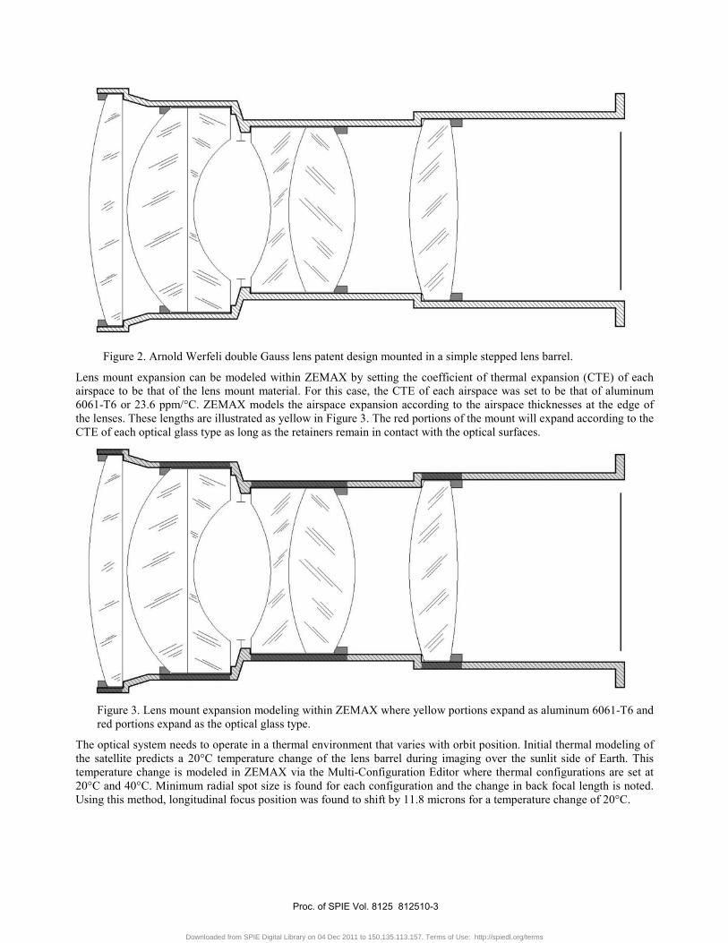
The fast Fourier transform point spread function tool in ZEMAX produces the diffraction pattern in Figure 8 for the above Bahtinov mask at focus for a perfect optical system. The “perfect” optical system is a 75 mm focal length, f/2.5 parabolic mirror imaging on-axis.
Proc. of SPIE Vol. 8125 812510-6
Downloaded from SPIE Digital Library on 04 Dec 2011 to 150.135.113.157. Terms of Use: http://spiedl.org/terms
a.
Figure 8. Simulated diffraction pattern created by Bahtinov mask (logarithmic).
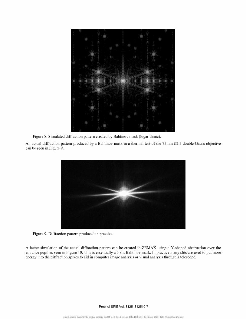
An actual diffraction pattern produced by a Bahtinov mask in a thermal test of the 75mm f/2.5 double Gauss objective can be seen in Figure 9.
Figure 9. Diffraction pattern produced in practice.
A better simulation of the actual diffraction pattern can be created in ZEMAX using a Y-shaped obstruction over the entrance pupil as seen in Figure 10. This is essentially a 3 slit Bahtinov mask. In practice many slits are used to put more energy into the diffraction spikes to aid in computer image analysis or visual analysis through a telescope.
Proc. of SPIE Vol. 8125 812510-7
Downloaded from SPIE Digital Library on 04 Dec 2011 to 150.135.113.157. Terms of Use: http://spiedl.org/terms
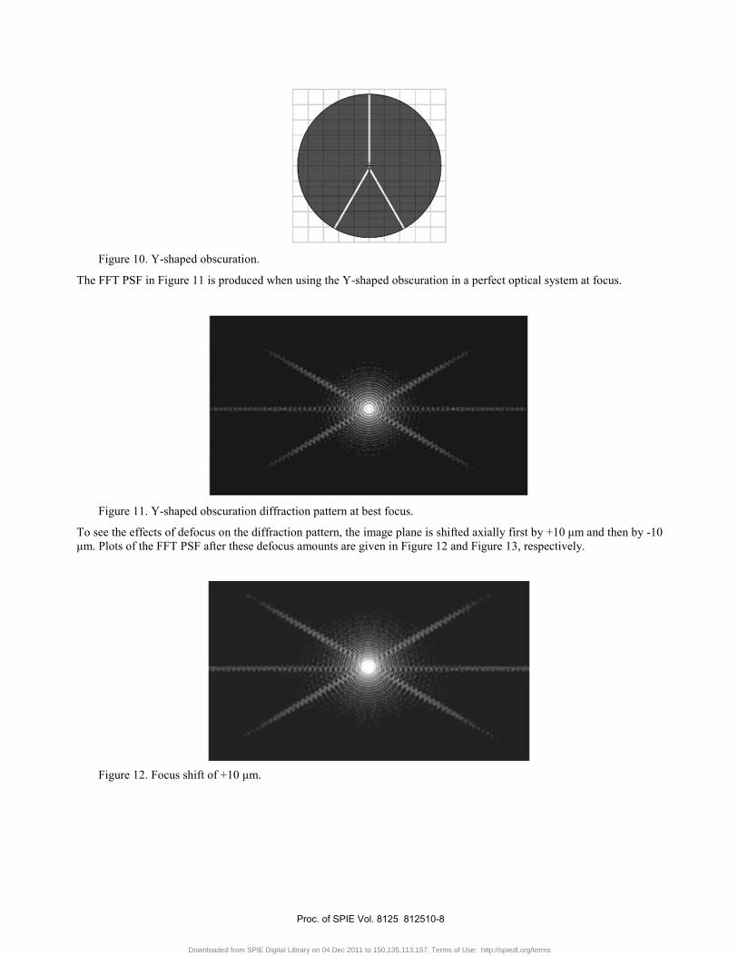
Figure 10. Y-shaped obscuration.
The FFT PSF in Figure 11 is produced when using the Y-shaped obscuration in a perfect optical system at focus.
Figure 11. Y-shaped obscuration diffraction pattern at best focus.
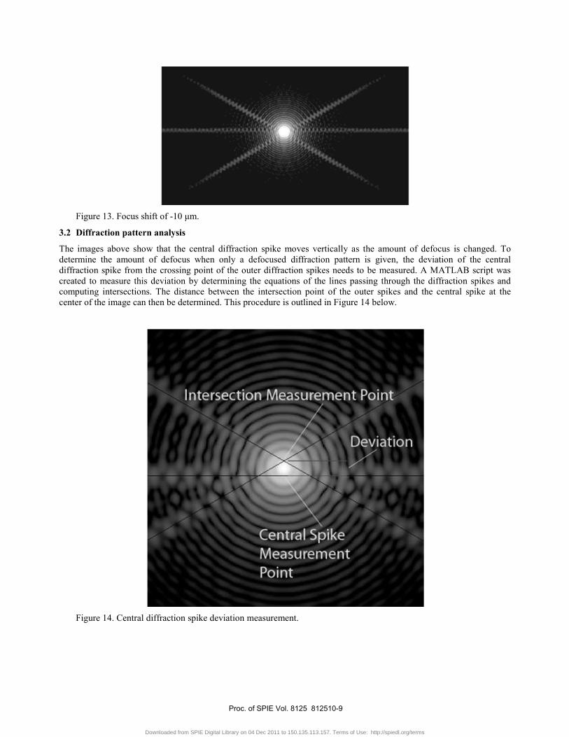
To see the effects of defocus on the diffraction pattern, the image plane is shifted axially first by +10 μm and then by -10 μm. Plots of the FFT PSF after these defocus amounts are given in Figure 12 and Figure 13, respectively.
Figure 12. Focus shift of +10 μm.
Proc. of SPIE Vol. 8125 812510-8
Downloaded from SPIE Digital Library on 04 Dec 2011 to 150.135.113.157. Terms of Use: http://spiedl.org/terms
0
Intersectiojvieasurement Point
Deviati n
ntral SpikeMeasurement
8ccS
4'
Figure 13. Focus shift of -10 μm.
3.2 Diffraction pattern analysis
The images above show that the central diffraction spike moves vertically as the amount of defocus is changed. To determine the amount of defocus when only a defocused diffraction pattern is given, the deviation of the central diffraction spike from the crossing point of the outer diffraction spikes needs to be measured. A MATLAB script was created to measure this deviation by determining the equations of the lines passing through the diffraction spikes and computing intersections. The distance between the intersection point of the outer spikes and the central spike at the center of the image can then be determined. This procedure is outlined in Figure 14 below.
Figure 14. Central diffraction spike deviation measurement.
Proc. of SPIE Vol. 8125 812510-9
Downloaded from SPIE Digital Library on 04 Dec 2011 to 150.135.113.157. Terms of Use: http://spiedl.org/terms

A linear relationship between defocus and central spike deviation was found in ZEMAX and Figure 15 is a plot of this relationship, also giving the linear equation for this specific model.
Figure 15. Diffraction spike shift vs. defocus for a perfect optical system.
Knowing the slope within the linear equation for a given optical system and diffraction mask, focus shift can be directly determined from a deviation measurement. In practice ZEMAX can be used to determine the slope if an accurate model of the optical system and diffraction mask is available.
3.3 COTS lens thermal test
This method of focal shift measurement was used to test the Leica double Gauss camera lens with its stock aluminum lens barrel. The stripped down camera lens is seen in Figure 16 with a Bahtinov mask over the aperture generated using a 3D printer. The lens is mounted in a thermal oven and coupled to a CCD camera. Thermocouples measure temperature of the outer housing of the barrel.
Figure 16. Leica camera lens in the thermal test oven.
-20 -15 -10 -5 0 5 10 15 20-6
-4
-2
0
2
4
6Central Diffraction Spike Shift vs. Defocus
Defocus (μm)
Diff
ract
ion
Spi
ke S
hift
( μm
)
y = 0.2583x
Proc. of SPIE Vol. 8125 812510-10
Downloaded from SPIE Digital Library on 04 Dec 2011 to 150.135.113.157. Terms of Use: http://spiedl.org/terms

ririrTrJQ
The collimator used in this test was a Maksutov telescope with a pinhole aperture at the eyepiece location illuminated by a white light source. This setup can be seen in Figure 17.
Figure 17. From left to right: thermal oven port, Maksutov telescope, pinhole, white light source.
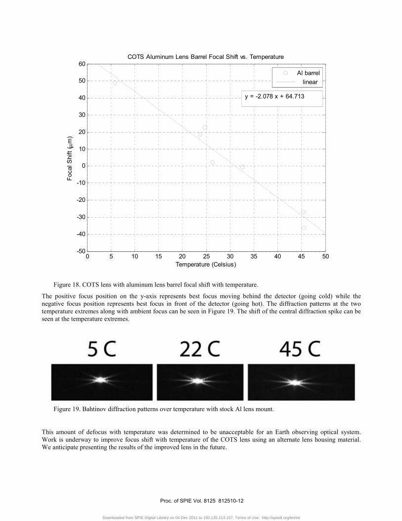
Best focus of the lens was achieved at ambient temperature and was left at that position during the entire test. The lens is then brought to the hot temperature and allowed to come to thermal equilibrium. Measurements of focus error are taken and the same procedure is repeated for a cold temperature. Table 3 presents the results of the thermal test with the COTS aluminum housing and Figure 18 is a plot of the linear fit for the data points obtained.
Table 3. COTS lens with aluminum lens barrel thermal test results.
Lens Housing Temp (Celsius)
Focus Position (μm)
Regression Focus (μm)
Residual (μm)
5.8 48.897 52.6606 3.7636
23.8 18.63 15.2566 -3.3734
24.8 22.626 13.1786 -9.4474
26.3 2.16 10.0616 7.9016
32.6 -0.54 -3.0298 -2.4898
45.4 -26.92575 -29.6282 -2.7024
45.5 -36.18 -29.836 6.344
Proc. of SPIE Vol. 8125 812510-11
Downloaded from SPIE Digital Library on 04 Dec 2011 to 150.135.113.157. Terms of Use: http://spiedl.org/terms
5C 22C 45C
Figure 18. COTS lens with aluminum lens barrel focal shift with temperature.
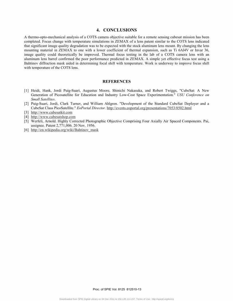
The positive focus position on the y-axis represents best focus moving behind the detector (going cold) while the negative focus position represents best focus in front of the detector (going hot). The diffraction patterns at the two temperature extremes along with ambient focus can be seen in Figure 19. The shift of the central diffraction spike can be seen at the temperature extremes.
Figure 19. Bahtinov diffraction patterns over temperature with stock Al lens mount.
This amount of defocus with temperature was determined to be unacceptable for an Earth observing optical system. Work is underway to improve focus shift with temperature of the COTS lens using an alternate lens housing material. We anticipate presenting the results of the improved lens in the future.
0 5 10 15 20 25 30 35 40 45 50-50
-40
-30
-20
-10
0
10
20
30
40
50
60
Temperature (Celsius)
Foca
l Shi
ft ( μ
m)
COTS Aluminum Lens Barrel Focal Shift vs. Temperature
Al barrel linear
y = -2.078 x + 64.713
Proc. of SPIE Vol. 8125 812510-12
Downloaded from SPIE Digital Library on 04 Dec 2011 to 150.135.113.157. Terms of Use: http://spiedl.org/terms
4. CONCLUSIONS A thermo-opto-mechanical analysis of a COTS camera objective suitable for a remote sensing cubesat mission has been completed. Focus change with temperature simulations in ZEMAX of a lens patent similar to the COTS lens indicated that significant image quality degradation was to be expected with the stock aluminum lens mount. By changing the lens mounting material in ZEMAX to one with a lower coefficient of thermal expansion, such as Ti 6Al4V or Invar 36, image quality could theoretically be improved. Thermal focus testing in the lab of a COTS camera lens with an aluminum lens barrel confirmed the poor performance predicted in ZEMAX. A simple yet effective focus test using a Bahtinov diffraction mask aided in determining focal shift with temperature. Work is underway to improve focus shift with temperature of the COTS lens.
REFERENCES
[1] Heidt, Hank, Jordi Puig-Suari, Augustus Moore, Shinichi Nakasuka, and Robert Twiggs, "CubeSat: A New Generation of Picosatellite for Education and Industry Low-Cost Space Experimentation." USU Conference on Small Satellites.
[2] Puig-Suari, Jordi, Clark Turner, and William Ahlgren. "Development of the Standard CubeSat Deployer and a CubeSat Class PicoSatellite." EoPortal Director. http://events.eoportal.org/presentations/7053/8502.html
[3] http://www.cubesatkit.com [4] http://www.cubesatshop.com [5] Werfeli, Arnold. Highly Corrected Photographic Objective Comprising Four Axially Air Spaced Components. Pai,
assignee. Patent 2,771,006. 20 Nov. 1956. [6] http://en.wikipedia.org/wiki/Bahtinov_mask
Proc. of SPIE Vol. 8125 812510-13
Downloaded from SPIE Digital Library on 04 Dec 2011 to 150.135.113.157. Terms of Use: http://spiedl.org/terms