thermo-mechanical treatment of glass- balloon-dispersed ......4 thermo-mechanical treatment of...
TRANSCRIPT

4
Thermo-Mechanical Treatment of Glass-Balloon-Dispersed Metal Matrix Composite
Osamu Umezawa Yokohama National University
Japan
1. Introduction
Mechanical aspects of recycled composites are demonstrated in this chapter. Aluminium
and its alloys are probably the most widely used matrix materials for metal matrix
composites (MMCs) (Rodriguez-Castro, 2002). Although reinforcements in the form of
continuous and discontinuous fibers have already been investigated in detail (Yu & Lee,
2000), discontinuous reinforcements such as those of dispersoids have also become more
popular. Subsequent working of such dispersoid-reinforced MMCs can enhance their
mechanical properties (Seah & Hemanth, 2007). Aluminium alloy/glass composites cast
with glass particles of sizes in the range of several tens of micrometers have been fabricated
and have exhibited superior mechanical properties with regard to strength and wear
resistance (Nicom & Nomura, 2006; Gibson & Ashby, 1999).
Since magnesium is the lightest metal in the structural materials, magnesium alloys also
have great potential for applications in automotive and aerospace industries. Furthermore,
solid-state recycling processes of magnesium alloy chips and/or fragments such as hot
extrusion, mechanical alloying, equal channel angular extrusion (ECAE) and cyclically
repeated plastic working (RPW) have been developed (Mabuchi et al., 1995; Clark et al.,
1997; Kondoh et al., 2003a, 2003b; Kondoh & Luagnvaranaunt, 2003c). The recycled
materials show superior mechanical properties such as high strength and high strain-rate
super-plasticity. Kondoh et al. (Kondoh & Luagnvaranaunt, 2003c) has established a process
to fabricate high performance magnesium composite, in which Mg2Si and MgO particles
were synthesized due to deoxidization of SiO2 glass by magnesium, and a refinement of
both those dispersoids and magnesium matrix grains was achieved during RPW. Under
only 2 mass% SiO2 addition in AZ31 alloy, the Mg2Si compound was employed as a
reinforcement of the composite, because of its high hardness, high Young’s modulus and
superior corrosion resistance. In order to fabricate the composites of glass balloons and
magnesium alloy chips, however, their mixture should be consolidated with the condition
for synthesis of Mg2Si and MgO phases.
On the other hand, various porous metals have been fabricated and their specific properties such as ultra-lightweight and low strength have been considered with more attention (Gibson & Ashby, 1999). Further, porous ceramics (e.g., Al2O3, ZrO2, TiO2, SiC, TiC, ZrC, etc.) have been used to develop ceramic matrix composites by various processing routes such as the melt stirring process and pressure infiltration technique (Chou et al., 2000;
www.intechopen.com

Metal, Ceramic and Polymeric Composites for Various Uses
80
Wilkes et al., 2006; Cao et al., 2004a, 2004b; Rambo et al., 2004, 2005). Therefore, the dispersion of porous particles in a metal matrix is one of the methods employed to control the size and distribution of the cell structure in the composite. Recently, new recyclable materials composed of recycled aluminium and glass balloons have been developed (Kashiwaya et al., 1999) and fabricated for building panels (Naigai Building Materials Corporation). However, in order to take the maximum advantage of their specific properties such as ultra lightweight and good electromagnetic shielding for mechanical or electronic parts, a workability that can deform them into any form is required. Since the balloon is a brittle second-phase particle, it is necessary to include either a thermomechanical treatment to plasticize the composite or perform near-net-shape casting. Umezawa et al. (Umezawa & Nagai, 1999) developed a repeated thermomechanical treatment (RTMT) to refine the microstructure of Al-Si cast materials; the materials successfully obtained good plasticity by this treatment. The RTMT was adopted to control the microstructure of the glass-balloon-dispersed aluminium alloy (AC3A) matrix composite in order to achieve a satisfactory stress-strain relationship and ductility for the composite (Shiga & Umezawa, 2007). Furthermore, the mixture of glass balloons and AZ31 magnesium alloy chips was thermomechanically treated to form their composite with Mg2Si and MgO phases.
2. Tensile and compressive properties of glass-balloon-dispersed aluminium alloy composite
A repeated thermomechanical treatment (RTMT) was adopted to control the microstructure of a glass-balloon-dispersed aluminium alloy (AC3A) composite. The RTMT, which involves the repetition of a multi-step process and followed by heat treatment, was applied to a cast plate of the composite. The composite was successfully worked into a rod or sheet by either swaging or flat rolling. The porous glass balloons were deformed or cracked so that the composite could be worked easily. The swaged material exhibited higher tensile strength, Young’s modulus, and elongation as compared to the cast material. The composite materials also exhibited excellent energy absorption properties.
2.1 Microstructural modification by repeated thermomechanical treatment 2.1.1 Test material The test material (AC) was a 10-mm-thick cast plate (AlceliteTM (Naigai Building Materials
Corporation)), which consisted of a recycled glass balloon and aluminium alloy AC3A. The
major compositions of the glass balloon were 68 SiO2, 6.3 Al2O3, 0.6 Fe2O3, 0.6 MgO, 9.5 CaO,
11.7 Na2O, and 1.3 K2O in mass%. The major properties of the AC and AC3A are listed in
Table 1. Figure 1 shows the microstructure of the AC material and glass balloon. The porous
Material Tensile strength,B /MPa
Compressive strength, C /MPa
Bending strength,D /MPa
Bending elastic
modulus, G /MPa
Thermal
conductivity,/W・m–1K–1
Thermal expansion coefficient,
/ × 10–6K–1
AC 15.7 49 41.2 144 54.4 16.5
AC3A 170 170 196 686 217.7 23.6
Table 1. Mechanical and thermal properties of the test material (AC) and AC3A.
www.intechopen.com

Thermo-Mechanical Treatment of Glass-Balloon-Dispersed Metal Matrix Composite
81
glass balloon with a diameter of approximately 1 mm is dispersed in the AC3A matrix. The balloon contains numerous closed bubbles. The specific gravities of the glass balloon and AC3A are 1.58 × 10⁻⁴ and 2.7 g/cm3, respectively. The specific gravity of the AC material, which was measured with a rectangular bar of dimensions 9.57 x 9.47 x 32 mm, was obtained as 1.5 g/cm3. The volume fraction of the glass balloon was estimated to be approximately half in the AC. The material annealed at 793 K for 1.8 ks was designated as AN.
(a) (b)
Fig. 1. Microstructure of the (a) AC material dispersed glass balloons in the AC3A matrix and (b) whole view of a glass balloon.
2.1.2 Repeated thermomechanical treatment and modified microstructure In order to avoid fracture, the AN samples were worked in multiple steps with intermediate
annealing at 793 K for 1.8 ks by using the RTMT process (Umezawa & Nagai, 1999). The
samples were machined either as round bars (10 mm in diameter × 150 mm in length) for
swaging or as plates (10 mm in thickness × 20 mm in width × 200 mm in length) for flat-
rolling. After the samples were worked by either swaging or flat-rolling in multiple steps at
room temperature, they were formed into a rod (CS) or sheet (CR). The reduction in section
area per working step was approximately 10%, and the working-annealing cycle was
repeated for a total section area reduction of approximately 90%. For the resulting RTMT
materials in the final state, a multiple-step process involving either swaging or flat-rolling
was performed at a different value of total section area reduction. The working strains were
defined as = ln A0/A, where denotes the working strain; A0, the initial section area of the
sample; and A, the section area of the worked sample. The specific gravities of the worked
CR and the selected CS samples (= 0.46 and 1.38) were measured and their microstructures
were observed. In the final step, the samples with or without annealing were indicated as -H
or -A, respectively.
The specific gravity of the materials increases from 1.5 to 2.3 g/cm3 with the working strain
up to = 2.6 (Fig. 2). This indicates that the relative density of the materials increases. In the
case of rolling, a linear relationship is obtained between the working strain and specific
gravity. However, the CS material exhibits a higher value of specific gravity for a lower
working strain. Although the data plots for the CS material are limited, the glass balloons in
www.intechopen.com

Metal, Ceramic and Polymeric Composites for Various Uses
82
the CS after swaging may be divided and aligned along the working direction with a lower
working strain due to a type of hydrostatic stress effect.
Fig. 2. Variation in the specific gravity of the test material during swaging or rolling. (Shiga & Umezawa, 2007)
Then microstructures of the composites after swaging or rolling was observed and compared, as shown in Figs. 3 and 4. Rod-like voids in the CS (Figs. 3c and 3d) or pancake-like voids in the CR (Figs. 4c and 4d) are observed at higher working strains. The porous balloons may be cracked and dropped from the sample surface. Comparing the microstructure in the transverse section of the CS and CR materials that were worked at lower working strains, it is observed that the radius of the voids in the CS (Fig. 3b) is lower than that in the CR (Fig. 4b). This observation agrees with the higher value of specific gravity at lower working strains.
2.2 Tensile and compressive properties 2.2.1 Tensile properties
A tensile test was performed for the AC, AN, and CS ( = 1.38) materials. Smooth-type specimens with a gauge diameter of 3.5 mm and length of 30 mm were used for the AC and AN materials. For the CS, the specimens were obtained from rods parallel to the longitudinal direction, and the gauge geometry was mechanically polished to obtain a
www.intechopen.com

Thermo-Mechanical Treatment of Glass-Balloon-Dispersed Metal Matrix Composite
83
diameter of 2.4 mm. The elongation was monitored by a clip gauge with the knife-edges set onto the tensile specimen. Its gauge length was 25 mm. A crosshead speed of 0.5 mm/min was selected in a motor-driven testing machine at 293 K (in air) under displacement control.
Fig. 3. Microstructure of the CS materials in the longitudinal section (a) and (c) and
transverse section (b) and (d): (a),(b) = 0.46 and (c),(d) = 1.38. (Shiga & Umezawa, 2007)
Fig. 4. Microstructure of the CR materials with working strain (a),(b) = 0.41 and (c),(d) = 1.38. (Shiga & Umezawa, 2007)
www.intechopen.com

Metal, Ceramic and Polymeric Composites for Various Uses
84
Figure 5 shows the tensile stress-strain curves and Table 2 summarizes the tensile properties. The swaged materials (CS-H and CS-A) exhibit higher values of Young’s modulus as compared to the cast materials (AC and AN). This may be related to the increase in specific gravity due to deformation of the balloons. The tensile strength of the CS materials is approximately thrice that of the cast materials. The RTMT not only increases the specific gravity but also the uniform elongation. The CS materials exhibit necking instability; however, the cast materials are fractured before approaching it. Hence, a microstructural modification by the RTMT could result in the avoidance of early fracture due to tension, which is characteristic of the cast materials. The load drops that appear in the curves of the swaged materials and the early fracture in the cast materials may result from the instantaneous separation between the balloons and the matrix. In fact dimple in the matrix traced the interface with dropped glass-balloon or brittle fractured glass-balloon mostly covers the fracture surface of the AC, as shown in Fig. 6a. The manner in which these fracture occurred was not detected in the CS. The annealing at 793 K for 1.8 ks results in higher uniform elongation in both the AC and CS materials. In particular, the annealed CS material (CS-A) showed an excellent elongation up to a strain of approximately 20%. This manner is typical of materials that undergo the RTMT (Umezawa & Nagai, 1999). Although delamination is detected in the tensile fracture in the CS materials, as shown in Fig. 6b, the RTMT may allow greater flexibility in the working of the composite.
Fig. 5. Stress-strain curves in the tensile test. (Shiga & Umezawa, 2007)
Material 0.2% proof stress, 0.2 /MPa
Tensile strength, B /MPa
Elongation, El /%
Young’s modulus, /GPa
AC 15 15 1.4 2.2
AN 14 17 2.7 1.9
CS-H 35 49 2.7 5.2
CS-A 27 54 19 5.3
Table 2. Tensile properties of the CS materials. (Shiga & Umezawa, 2007)
www.intechopen.com

Thermo-Mechanical Treatment of Glass-Balloon-Dispersed Metal Matrix Composite
85
The area fraction of the matrix in the transverse section of the CS is higher than that of the AC, and the matrix in the CS continuously exists along the tensile direction in the form of a fiber. Therefore, the CS may exhibit the tensile performance of the aluminium matrix rather than the AC; such behaviour results from the reduction in the stress concentration, which induces fracture of the matrix.
(a) (b)
Fig. 6. Fracture surfaces of the (a) AC and (b) CS-A. (Shiga & Umezawa, 2007)
2.2.2 Finite element analysis Interactive algorithms (Yamada, 2006) used for computing the averaged response of non-linear composites have been applied to microscopically analyse the tensile deformation in the elastic regime. For the AC, spherical glass balloons were installed into the aluminium matrix as a closed-cell foam. Pores were distributed in the balloon. For the CS, ellipsoidal (rod-like) pores were installed into the matrix since the balloon was collapsed into pieces and could be plastically deformed within the matrix. A simple stress analysis was applied to the materials in order to discuss the fracture manner and stress-strain relationship mentioned in above. Figure 7 shows an analysis map for the principal stress distribution under a microstrain in the elastic regime where the applied stress is 1 MPa in tension along the y axis. The stress concentration appears around the glass balloons. When a glass balloon represents as a sphere, its diameter along the y-axis is taken for the earth’s axis (NS). Then the equator is perpendicular to NS. The glass balloon at the
lower left in Fig. 7 represents a reference sphere. The compressive stress with the xx component is relatively high at both N and S poles (indicated by arrows in Fig. 7a). The
principal stress, yy, acts near the interface, especially around the equator. These behaviours agree with the stretching of the faces of the closed-cell foam under tension [6]. Thus, the tensile stress around the equator on the sphere occurs due to tension and may lead to
fracture. The stress concentration of the yy is estimated about three times of the applied stress. On the contrary, the compressive stress around the equator on the neighbouring
balloon occurs in Fig. 7b. The maximum magnitude of the yy in compression is almost the same in tension. These stress concentration phenomena agrees with the fracture surface shown in Fig. 6a. The brittle fractured glass-balloon may result from the concentrated tensile
www.intechopen.com

Metal, Ceramic and Polymeric Composites for Various Uses
86
stress, and the glass-balloon concentrated compressive stress may be separated from the matrix. Even though the interface strength between the glass-balloon and the matrix is very low, it reveals that the stress concentration around the equator on the glass-balloon may predominantly affect the tensile fracture behaviour.
(a)
(b)
Fig. 7. Principal stresses in the AC material: (a) xx and (b) yy. Applied tensile stress is 1 MPa and its direction is parallel to the y-axis. The area in white colour shows the pores in the glass balloon. Arrows in (a) indicate a compressive stress concentration part. Arrows in (b) indicate a tensile stress concentration part. (Shiga & Umezawa, 2007)
www.intechopen.com

Thermo-Mechanical Treatment of Glass-Balloon-Dispersed Metal Matrix Composite
87
In the case of the CS material, the stress concentration mostly appears near at both the top and bottom parts of the elongated pore, as shown in Fig. 8. The influence of tensile stress concentration at the ellipsoidal closed-cell foam due to fracture may be lower than that at the spherical foam, although the maximum magnitude of tensile stress concentration in the
CS is higher than that in the AC. The tensile stress of xx between elongated pores occurs. It may give an origin of delamination of the composite.
(a)
(b)
Fig. 8. Principal stresses in the CS-A material: (a) xx and (b) yy. Applied tensile stress is 1 MPa and its direction is parallel to the y-axis. The elongated pores are indicated in white colour. Arrows in both (a) and (b) indicate a tensile stress concentration part. (Shiga & Umezawa, 2007)
www.intechopen.com

Metal, Ceramic and Polymeric Composites for Various Uses
88
2.2.3 Compressive properties and energy absorption
A compressive test was also performed for the AC, AN, and CS ( = 0.46) materials. The cylindrical specimens were machined from rods parallel to the longitudinal direction. For the AC and AN materials, the diameter and height of the specimens were 9 mm. For the CS material, the diameter and height of the specimens were 6 mm. In the compressive test, the diameter at the centre of the specimen was measured by using a micrometer. In both the tests, a crosshead speed of 0.5 mm/min was selected in a motor-driven testing machine at 293 K (in air) under displacement control. Figure 9 schematically illustrates the compressive stress–strain curve of the porous material. The curve generally shows a very low increase in stress (plateau regime); this is followed by an acceleration in the stress (densification). The energy absorbed per unit volume up to a
strain at the transition point from the plateau to the accelerated level, 1, is defined as (Gibson & Ashby, 1999)
1
0W d
(1)
The absorbed energy is schematically shown by the hatched area in Fig. 9. The energy absorption efficiency, E, is also evaluated as
1
0
0 1
dE
(2)
Where, 0 is the stress at strain 1.
Fig. 9. Schematic illustration of compressive stress–strain curve in a porous material.
The plateau regime after linear elasticity appears in all the compressive stress-strain curves, as shown in Fig. 10. The arrows in Fig. 10 show the strain of the transition point from the plateau to the accelerated stress, 1 for the present evaluation. The higher the strain range of the plateau, the larger is the magnitude of energy absorption. When the material is compressed, the glass balloon within the AC3A matrix is compressed. The working during
www.intechopen.com

Thermo-Mechanical Treatment of Glass-Balloon-Dispersed Metal Matrix Composite
89
the plateau range may result in the plastic deformation of the matrix and fracture of the glass balloon. However, the balloon is brittle and collapses easily. It may then be harmonized with plastic deformation of the matrix. In fact, the energy absorption efficiency, E, of the AC and AN is approximately 0.8–0.9, as listed in Table 3; these values are excellent as they are similar to those of an open-cell foam material (nearly E = 1). There is a possibility to use this composite material instead of cell foam materials. The CS materials show lower inclination of linear elasticity and higher yield stress as compared to the AC and AN materials. Since the CS materials exhibited higher Young’s modulus and relative density, the linear elasticity may involve the effect of bending of the closed-cell. The glass-balloons were broken into pieces and could be easily deformed so that the matrix containing elongated pores might result in the lower modulus. The absorbed energy, W, of the CS material is considerably higher than that of the cast material, although the energy absorption efficiency is lower. This may be related to the lower inclination of linear elasticity of the CS.
Fig. 10. Stress-strain curves in the compressive test. The arrows indicate the strain, 1, for each curve. (Shiga & Umezawa, 2007)
Material 1 0
/MPa
W /MPa
E
AC 0.22 52 9.5 0.8
AN 0.20 46 8.0 0.9
CS-H 0.41 109 31 0.7
CS-A 0.38 143 39 0.7
Table 3. Energy absorption properties. Parameters W and E are the energy absorbed per unit volume as shown in Fig. 9 and the energy absorption efficiency, respectively.
3. Fabrication of glass-balloon-dispersed magnesium alloy composite
The mixture of glass-balloon and AZ31 magnesium alloy chips with 1:1 in volume was heated and extruded to form a brick of composites. The bricks were heat-treated in phase region, and their microstructure was characterized. As the heating time increased, oxidation
www.intechopen.com
Metal, Ceramic and Polymeric Composites for Various Uses
90
of magnesium was accelerated. As heat-treatment temperature was higher the oxidation was also promoted. The heat-treatment condition at 873 K - 1h was chosen to form Mg2Si. As press load increased, the volume fraction of Mg2Si was increased.
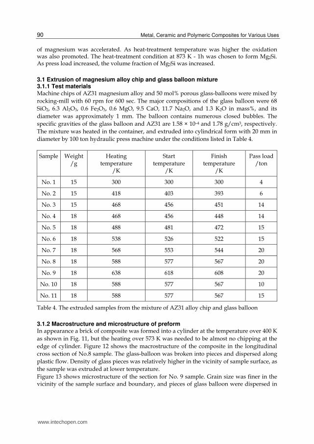
3.1 Extrusion of magnesium alloy chip and glass balloon mixture 3.1.1 Test materials Machine chips of AZ31 magnesium alloy and 50 mol% porous glass-balloons were mixed by
rocking-mill with 60 rpm for 600 sec. The major compositions of the glass balloon were 68
SiO2, 6.3 Al2O3, 0.6 Fe2O3, 0.6 MgO, 9.5 CaO, 11.7 Na2O, and 1.3 K2O in mass%, and its
diameter was approximately 1 mm. The balloon contains numerous closed bubbles. The
specific gravities of the glass balloon and AZ31 are 1.58 × 10⁻⁴ and 1.78 g/cm3, respectively.
The mixture was heated in the container, and extruded into cylindrical form with 20 mm in
diameter by 100 ton hydraulic press machine under the conditions listed in Table 4.
Sample Weight /g
Heating temperature
/K
Start temperature
/K
Finish temperature
/K
Pass load /ton
No. 1 15 300 300 300 4
No. 2 15 418 403 393 6
No. 3 15 468 456 451 14
No. 4 18 468 456 448 14
No. 5 18 488 481 472 15
No. 6 18 538 526 522 15
No. 7 18 568 553 544 20
No. 8 18 588 577 567 20
No. 9 18 638 618 608 20
No. 10 18 588 577 567 10
No. 11 18 588 577 567 15
Table 4. The extruded samples from the mixture of AZ31 alloy chip and glass balloon
3.1.2 Macrostructure and microstructure of preform In appearance a brick of composite was formed into a cylinder at the temperature over 400 K
as shown in Fig. 11, but the heating over 573 K was needed to be almost no chipping at the
edge of cylinder. Figure 12 shows the macrostructure of the composite in the longitudinal
cross section of No.8 sample. The glass-balloon was broken into pieces and dispersed along
plastic flow. Density of glass pieces was relatively higher in the vicinity of sample surface, as
the sample was extruded at lower temperature.
Figure 13 shows microstructure of the section for No. 9 sample. Grain size was finer in the vicinity of the sample surface and boundary, and pieces of glass balloon were dispersed in
www.intechopen.com

Thermo-Mechanical Treatment of Glass-Balloon-Dispersed Metal Matrix Composite
91
the matrix. Elemental analysis by EPMA demonstrated that fragmented glass-balloons were also distributed not only at the particle boundaries but also in the inside of garins as shown in Fig. 14, and that enriched oxygen was detected at the boundaries. Therefore the boundaries resulted from the interface of AZ31 magnesium alloy chips, and fragmented glass-balloons were partially contaminated there.
(a) (b)
Fig. 11. Sample side view (22 mm in height) (a) and bottom view (b) of No. 8
Fig. 12. Macrostructure of No. 8 in the longitudinal section
www.intechopen.com

Metal, Ceramic and Polymeric Composites for Various Uses
92
Fig. 13. Microstructure in the cross section of No. 9.
Fig. 14. Secondary electron image in the cross section of No. 8.
3.2 Solid-state synthesis of Mg2Si and MgO The DSC (differential scanning calorimeter) curves for the compacts in employing the elemental AZ31 and SiO2 glass powder mixture expect the exothermic peaks at 923 K due to the latent heat of magnesium melting and at 844 K (SiO2 glass transition temperature) due to
the phase transformation from to (Reynard et al., 1996). However, they showed the starting temperature of the exothermic at 730 K (Kondoh & Luagnvaranaunt, 2003c). Therefore, the deoxidizing SiO2 by magnesium has a large possibility to form Mg2Si and
www.intechopen.com

Thermo-Mechanical Treatment of Glass-Balloon-Dispersed Metal Matrix Composite
93
MgO by the reaction in eq.(3), although the ignition temperature in DSC curve may depend on the compositions and crystalline in the glass-balloon.
2 24Mg SiO Mg Si 2MgO (3)
3.2.1 Heat treatment of preform The samples were heat-treated in vacuum at the temperature of 773 K, 823 K, 873 K and 898 K for 1 hr. The heat-treated materials were characterized by X-ray diffraction (XRD) with
Cu-K1 radiation operated at 40 kV - 200 mA (range: 20-90 deg, step: 0.02, scan: 2 deg/min) and micro-Vickers hardness (load: 1 kg, holding time: 15 s). In the sample No. 2, a solid-state synthesis was available at the temperature heating over 873 K, and not at lower temperatures due to oxidation of magnesium chips. The isothermal
treatment at higher temperature may cause a partial remelting of magnesium phase. Then the No. 2 samples were heated at the temperatures of 873 K and 898 K for longer time to identify the reacted phases. Figure 15 summarized the estimated volume fractions of crystalline phases formed by isothermal heating, which were calculated from the integrated intensity of peaks in XRD profiles. As the heating time increased, the oxidation of magnesium was accelerated as well as deoxidization of SiO2. As heat-treatment temperature was higher, the oxidation was also promoted. As a result, the heat-treatment condition at 873 K for 1 h was chosen to form Mg2Si with less MgO.
Fig. 15. Effect of heat treatment on estimated volume fractions of crystalline phases for No.2 sample
3.2.2 Effect of press load on preform The samples extruded at about 573 K, i.e. No. 8, 10 and 11, were pressed with different load from 10 to 20 ton, so that the higher press load resulted in finer dispersion of glass balloons
www.intechopen.com

Metal, Ceramic and Polymeric Composites for Various Uses
94
and higher adhesion of matrix. Figure 16 showed the estimated volume fractions of crystalline phases after heating at 873 K for 1 h. The less deoxidization of SiO2 may be due to smaller faction of interface between SiO2 and magnesium, as the lower press load is. The No. 8 sample of pressed with load 20 ton exhibited much higher volume fractions of Mg2Si and MgO and showed 400 HV after the heat treatment.
Fig. 16. Effect of press load on the volume fraction of crystalline phases after heating at 873 K for the extruded samples at about 573 K
Fig. 17. Effect of press load on the hardness after heating at 873 K for the extruded samples at about 573 K
4. Conclusion
Thermomechanical treatments were adopted to control the microstructure of porous glass-balloon-dispersed aluminium alloy and magnesium alloy composites. The mechanical properties and the microstructure of the composite were characterized.
www.intechopen.com
Thermo-Mechanical Treatment of Glass-Balloon-Dispersed Metal Matrix Composite
95
The porous glass-balloon-dispersed AC3A aluminium alloy composite, which was subjected to the repeated thermomechanical treatment along with the working by either swaging or flat rolling, was successfully formed into a rod or sheet. Microstructural modification by the treatment avoided early fracture due to tension and resulted in good ductility. The swaged material exhibited higher tensile strength and Young’s modulus as compared to the cast material. A stress concentration around the glass balloons was confirmed. The stress may lead to fracture. The composite materials also exhibited excellent energy absorption properties. The swaged material showed lower inclination of linear elasticity and higher yielding stress as compared to the cast material. A new process for fabricating magnesium composites with a solid-state reaction by glass balloons has been proposed. The mixture of glass balloons and AZ31 magnesium alloy chips was thermomechanically treated to form their composite and applied to solid-state synthesis of Mg2Si and MgO phases. It demonstrated a possibility to employ SiO2 glass balloons to fabricate a lightweight magnesium alloy composite.
5. Acknowledgment
The author thanks S. Shiga, Y. Kosuge and Dr. S. Morooka for their help on the experimental works.
6. References
Cao, J., Rambo, C.R. & Sieber, H. (2004a), Preparation of porous Al2O3-Ceramics by biotemplating of wood, Journal of Porous Material, Vol. 11, No. 3, (July 2004), pp. 163-172, ISSN 1380-2224
Cao, J., Rusina, O. & Sieber, H. (2004b), Processing of porous TiO2-ceramics from biological preforms, Ceramics International, Vol. 30, No. 7, (2004), pp. 1971-1974, ISSN 0272-8842
Chou, S.-N., Huang, J.-L., Li, D.F. & Lu, H.-H. (2007), The mechanical properties and microstructure of Al2O3/aluminum alloy composites fabricated by squeeze casting, Journal of Alloys and Compounds, Vol. 436, No. 1-2, (June 2007), pp. 124-130, ISSN 0925-8388
Clark, C.R., Wright, C., Suyanarayana, C., Baburaj, E.G. & Froes, F.H., Synthesis of Mg2X (X = Si, Ge, or Sn) intermetallics by mechanical alloying, Materials Letters, Vol. 33, No. 1-2, (November 1997), pp. 71-75, ISSN 0167-577X
Gibson, L.J. & Ashby, M.F. (1999), Cellular Solids: Structure and Properties, 2nd ed., Cambridge University Press, Cambridge, UK, (July 1999), ISBN 9780521499118
Kashiwaya, K., Kasetani, N., Nagao, K. & Mitani, H. (1999), New recyclable material composed of aluminium & glass-balloon: part 1 general properties, Summaries of technical papers of Annual Meeting Architectural Institute of Japan A-1 Materials & construction, (July 1999), pp. 545-546, ISSN 1341-4437
Kondoh, K., Oginuma, H., Tsuzuki, R. & Aizawa, S. (2003a), Magnesium matrix composite with solid-state synthesized Mg2Si dispersoids, Materials Transactions, Vol. 44, No. 4, (April 2003), pp. 611-618, ISSN 1345-9678
Kondoh, K., Oginuma, H., Kimura, A., Matsukawa, S. & Aizawa, S. (2003b), In-situ synthesis of Mg2Si intermetallics via powder metallurgy process, Materials Transactions, Vol. 44, No. 5, (May 2003), pp. 981-985, ISSN 1345-9678
Kondoh, K. & Luagnvaranaunt, T. (2003c), New process to fabricate magnesium composites using SiO2 glass scraps, Materials Transactions, Vol. 44, No. 12, (December 2003), pp. 2468-2474, ISSN 1345-9678
www.intechopen.com

Metal, Ceramic and Polymeric Composites for Various Uses
96
Mabuchi, M., Kubota, K. & Higashi, K. (1995), New recycling process by extrusion for machined chips of AZ91 magnesium and mechanical properties of extruded bars, Materials Transactions JIM, Vol. 36, No. 10, (October 1995), pp. 1249-1254, ISSN 1345-9678
Naigai Building Materials Corporation, Alcelite, Available from http://www.naigai-technos.co.jp/kenzai/english/k_products.html
Nicom, N. & Nomura, H. (2006), Melt infiltration of SiCp reinforced Al matrix composite by newly designed pressure infiltration technique, Materials Science & Engnieering A, Vol. 441, No. 1-2, (December 2006), pp. 97-105, ISSN 0921-5090
Rambo, C.R., Cao, J. & Sieber, H. (2004), Preparation and properties of highly porous, biomorphic YSZ ceramics, Material Chemistry Physics, Vol. 87, No. 2-3, (August 2004), pp. 345-352, ISSN 0254-0584
Rambo, C.R., Cao, J., Rusina, O. & Sieber, H. (2005), Manufacturing of biomorphic (Si, Ti, Zr)-carbide ceramics by sol–gel processing, Carbon, Vol. 43, No. 6, (May 2005), pp. 1174-1183, ISSN 0008-6223
Reynard, B., Takir, F., Guyot, F., Gawanmesia, G.D., Liebermann, R.C. & Gillet, P. (1996), High-temperature Raman spectroscopic and X-ray diffraction study of -Mg2SiO4: Insights into its high-temperature thermodynamic properties and the to phase-transformation mechanism and kinetics, American Mineralogist, Vo. 81, No. 5-6, (June 1996), pp. 585-594, ISSN 0003-004X
Rodriguez-Castro, R. (2002), Microstructure and mechanical behavior of functionally graded Al A359/SiCp composite, Materials Science & Engineering A, Vol. A323, No. 1-2, (January 2002), pp. 445-456, ISSN 0921-5090
Seah, K.H.W. and Hemanth, J. (2007), Cryogenic effects during casting on the wear behavior of aluminum-alloy/glass MMCs, Composites: Part A, Vol. 38, No. 5, (May 2007), pp. 1395-1402, ISSN 1359-835X
Shiga, A. & Umezawa, O. (2007), Effects of thermo-mechanical treatment on the tensile and compressive properties of a glass-balloon-dispersed aluminum alloy composite, Materials Transactions, Vol. 48, No. 12, (December 2007), pp. 3088-3094, ISSN 1345-9678
Shorowordi, K.M., Laoui, T., Haseeb, A.S.M.A., Celis, J.P. & Froyen, L. (2003), Microstructure and interface characteristics of B4C, SiC and Al2O3 reinforced Al matrix composites: a comparative, Journal of Material Process & Technology, Vol. 142, No. 3, (December 2003), pp. 738-743, ISSN 0924-0136
Umezawa, O. & Nagai, K. (1999), Microstructural refinement of as cast Al-12.6wt%Si alloy by repeated thermomechanical treatment to produce a heavily deformable material, Metallurgical Materials Transactions A, Vol. 30A, No. August, (August 1999), pp. 2221-2228
Wilkes, T.E., Young, M.L., Sepulveda, R.E., Dunand, D.C. & Faber, K.T. (2006), Composites by aluminum infiltration of porous silicon carbide derived from wood precursors, Scripta Materialia, Vol. 55, No. 12, (December 2006), pp. 1083-1086, ISSN 1359-6462
Yamada, T. (2006), Iterative algorithms for computing the averaged response of nonlinear composites under stress-controlled loadings, International Journal for Multiscale Computational Engineering, Vol. 4, No. 4, (2006), pp. 475-486, ISSN 1543-1649
Yu, X.X. & Lee, W.B. (2000), The design and fabrication of an alumina reinforced aluminum composite material, Composites: Part A, Vol. 31, No. 3, (March 2000), pp. 245-258, ISSN 1359-835X
www.intechopen.com

Metal, Ceramic and Polymeric Composites for Various UsesEdited by Dr. John Cuppoletti
ISBN 978-953-307-353-8Hard cover, 684 pagesPublisher InTechPublished online 20, July, 2011Published in print edition July, 2011
InTech EuropeUniversity Campus STeP Ri Slavka Krautzeka 83/A 51000 Rijeka, Croatia Phone: +385 (51) 770 447 Fax: +385 (51) 686 166www.intechopen.com
InTech ChinaUnit 405, Office Block, Hotel Equatorial Shanghai No.65, Yan An Road (West), Shanghai, 200040, China
Phone: +86-21-62489820 Fax: +86-21-62489821
Composite materials, often shortened to composites, are engineered or naturally occurring materials madefrom two or more constituent materials with significantly different physical or chemical properties which remainseparate and distinct at the macroscopic or microscopic scale within the finished structure. The aim of thisbook is to provide comprehensive reference and text on composite materials and structures. This book willcover aspects of design, production, manufacturing, exploitation and maintenance of composite materials. Thescope of the book covers scientific, technological and practical concepts concerning research, developmentand realization of composites.
How to referenceIn order to correctly reference this scholarly work, feel free to copy and paste the following:
Osamu Umezawa (2011). Thermo-Mechanical Treatment of Glass-Balloon-Dispersed Metal Matrix Composite,Metal, Ceramic and Polymeric Composites for Various Uses, Dr. John Cuppoletti (Ed.), ISBN: 978-953-307-353-8, InTech, Available from: http://www.intechopen.com/books/metal-ceramic-and-polymeric-composites-for-various-uses/thermo-mechanical-treatment-of-glass-balloon-dispersed-metal-matrix-composite

© 2011 The Author(s). Licensee IntechOpen. This chapter is distributedunder the terms of the Creative Commons Attribution-NonCommercial-ShareAlike-3.0 License, which permits use, distribution and reproduction fornon-commercial purposes, provided the original is properly cited andderivative works building on this content are distributed under the samelicense.