thermally controlled growth of carbon onions within porous...
TRANSCRIPT

RSC Advances
PAPER
Publ
ishe
d on
23
Febr
uary
201
5. D
ownl
oade
d by
Ope
n U
nive
rsity
on
14/0
4/20
15 1
2:03
:53.
View Article OnlineView Journal | View Issue
Thermally contro
aAustralian Centre for Research on Separat
University of Tasmania, Hobart, Tasmania, AbIrish Separation Science Cluster, National
University, Dublin 9, IrelandcDepartment of Engineering and Innovation,
6AA, UKdARC Centre of Excellence for Electromater
University of Tasmania, Hobart, Tasmania,
† Electronic supplementary informa10.1039/c5ra00258c
Cite this: RSC Adv., 2015, 5, 22906
Received 7th January 2015Accepted 19th February 2015
DOI: 10.1039/c5ra00258c
www.rsc.org/advances
22906 | RSC Adv., 2015, 5, 22906–229
lled growth of carbon onionswithin porous graphitic carbon-detonationnanodiamond monolithic composites†
E. Duffy,a X. He,b E. P. Nesterenko,b D. Brabazon,b A. Dey,c S. Krishnamurthy,c
P. N. Nesterenkoa and B. Paull*ad
Unique porous carbon monoliths containing thermally annealed carbon onions, were prepared from a
resorcinol formaldehyde precursor rod, containing silica gel acting as a hard template, detonation
nanodiamond, and Fe3+ as a graphitisation catalyst. Detonation nanodiamond was converted to carbon
onions during controlled pyrolysis under N2, where the temperature cycle reached a maximum of 1250�C. Thermal characterisation and high resolution electron microscopy have confirmed the graphitisation
of nanodiamond, and revealed the resulting quasi-spherical carbon onions with an average particle size
of 5.24 nm. The bimodal porous composite contains both macropores (5 mm) and mesopores (10 nm),
with a BET surface area of 214 m2 g�1 for a nanodiamond prepared monolith (0.012 wt% nanodiamond
in the precursor mixture), approximately twice that of blank monoliths, formed without the addition of
nanodiamond, thus providing a new approach to increase surface area of such porous carbon rods.
Raman spectroscopy and X-ray photoelectron spectroscopy also confirmed an enhanced graphitisation
of the monolithic carbon skeleton resulting from the elevated thermal conductivity of the added
nanodiamond. TEM imaging has confirmed the nanodiamond remains intact following pyrolysis at
temperatures up to 900 �C.
Introduction
New porous materials continue to attract signicant interestwithin the science and technology community due to theirunique and versatile properties, and advanced applications.1 Inparticular, the design of porous carbon materials with tailoredchemical and structural properties has immense signicancewithin the fabrication, coatings and coating and energy storagebased industries, addressing key technological challenges. Forporous carbons, these properties include high specic surfacearea, chemical inertness, thermal stability and electronicconductivity. The use of porous carbons as an electrode mate-rial2 and indeed in electrochemical double layer capacitors, orsuper capacitors3 is therefore currently very topical. In the areaof environmental technology, there are reports demonstrating
ion Science, School of Physical Sciences,
ustralia. E-mail: [email protected]
Centre for Sensor Research, Dublin City
The Open University, Milton Keynes MK7
ials Science, School of Physical Sciences,
Australia
tion (ESI) available. See DOI:
15
utility as catalyst supports, e.g. for gas separation or storage,4,5
and as adsorbents for separation or remediation processes.6
Several excellent reviews on the subject of porous carbonproduction and applications have recently emerged.7–9 One novelroute to the production of porous carbon materials is theformation of so-called carbonmonoliths. These typically exhibit ahierarchical porous structure, and are oen produced throughvarious templatingmethods, for example the use of hard and soremovable templates. Silica particles (including mesoporoussilica or silica nanoparticles) are commonly used in the hard-templating synthesis of porous carbon monoliths, to facilitatecreation of a controlled macroporous structure in the nalmaterial. The inorganic template is embedded in the carbonprecursor, or the carbon precursor is introduced into the pores ofthe template. Aer undergoing carbonisation via pyrolysis, thetemplate is removed, thus generating a porous material withisolated pores or an interconnected pore network. Mesoporesmay also be created by catalytic graphitisation and this iscommonly achieved using a metal ion catalyst, or by the car-bonisation of a polymer blend containing a carbon precursorpolymer and a decomposable polymer that is removed to producethe pores. Reports on the production of such hierarchical porouscarbons with bimodal pore structures have been published,7–10
several of which are based on the polymerisation and carbon-isation of silica particle embedded resorcinol formaldehyde (RF)resin, using Fe3+ as a catalyst to enhance graphitisation.10,11
This journal is © The Royal Society of Chemistry 2015
Paper RSC Advances
Publ
ishe
d on
23
Febr
uary
201
5. D
ownl
oade
d by
Ope
n U
nive
rsity
on
14/0
4/20
15 1
2:03
:53.
View Article Online
Porous carbon monoliths offer inter-connected channelswithin their pore network, with a high ow-through perme-ability, good thermal and electrical conductivity hence theirpotential application in adsorption or separation processes,10–12
and electrochemical energy storage applications.13 Recently, theuse of nanocarbons to form porous carbon monoliths orcarbon–carbon composite materials has produced someexciting results, showing considerably enhanced electro-chemical properties for potential applications in the aboveareas.14,15 Indeed, changes to the physical, chemical and elec-trochemical properties of the nano-composite monoliths havebeen reported, when compared to simple carbon monolithswithout embedded or surface exposed nanocarbons. Physicalenhancements include higher specic surface area, greatermesopore volume and a narrower pore size distribution.16
However, to-date such studies are limited in number, andcontrolled approaches to achieve substantially enhanced prop-erties, e.g. surface area, for such monolithic substrates arerather limited.
It can be expected that with the inclusion of nanocarbonswithin porous carbon monoliths, there will be a transfer ofunique physical–chemical properties to the nal composite,provided the nanocarbon is preserved through any carbon-isation process. These unique nanocarbon properties haveseen them applied in a wide variety of ways in recent times,e.g. in environmental applications as sensors, lters, andsorbents,17 with fullerenes, carbon nanotubes and carbononions having demonstrated high sorption capacities fororganic pollutants and heavy metal contaminants.18 Recently,nanodiamond (ND) has received renewed attention, primarilydue to its biocompatibility and potential applications indrug delivery.19,20 Nanoscale diamond (sp3 carbon) may beproduced by detonation synthesis, where the detonationsoot is puried under oxidative acidic conditions to yielddetonation nanodiamond (DND), which is known to have ahigh thermal conductivity, mechanical stability and surfacechemistry readily amenable to functionalisation. Carbononions may be produced by the thermal annealing of ND21 inan inert atmosphere or under vacuum. They too have avariety of interesting properties (such as high surface area andelectrical conductivity), making them of interest for usein supercapacitors,22 lubrication, and in environmentalremediation.18
Therefore, herein is described a novel route for the prep-aration and characterisation of a new porous carbon mono-lith with signicantly enhanced surface area and graphiticcharacter, via embedded carbon onions produced throughthe controlled thermal annealing of DND during the car-bonisation process. The new carbon on carbon compositematerial was formed by pyrolysis of a precursor rod con-taining a mixture of RF resin, silica particles and DND, with aFe3+ catalyst used to increase localised graphitisation. Thethermal conductivity of the DND was also expected toenhance the graphitisation process, and the precise thermalconversion of diamond particles to carbon onions during thepyrolysis (to a maximum temperature of 1250 �C) wasexplored.
This journal is © The Royal Society of Chemistry 2015
ExperimentalSynthesis of graphitic carbon monoliths with thermallyannealed carbon onions
Fig. 1(A) to 1(C) illustrates the steps taken in preparing the nano-composite porous graphitic carbon monoliths, and a blankcarbon monolithic material (containing no additional DND). Theprecursor solution (A) is composed of a polymeric mixture con-taining a RF resin in 1-butanol. In preparation of this solution, 1 gof 5 mm silica particles, with a surface area of 359 m2 g�1 and apore size of 550 �A, (Nucleosil silica beads from Macherey-Nagel,Duren, Germany) was dispersed in 1.85 mL 1-butanol and soni-cated for 1 hour before adding 0.18 g of ferric chloride (99%Riedel-De Haen, Seelze, Hannover, Germany) and 0.367 g ofresorcinol (99% Sigma-Aldrich, Dublin, Ireland). A 555 mL aliquotof aqueous DND suspension (Single Digit Nanodiamond, 50 mgmL�1 aqueous suspension, PlasmaChem GmbH Germany) wasadded to this RF polymeric resin, as a percentage (30%) of thetotal volume of 1-butanol present. The addition of 0.3 g of ice-cooled formaldehyde (37 wt% solution, Sigma-Aldrich, Dublin,Ireland) to the mixture was made, with constant stirring.Following stirring in an ice-bath for 1 hour, the resin was trans-ferred to a 7 mm i.d. glass tube, which was capped and sealed forpolymerisation at 90 �C in a water bath (GFL water bath fromLaborggerateborse GmbH, Burladingen, Germany) for 15 hours. Asolid rod was formed, which was detached slightly from the wallsof the tube due to shrinkage during polymerisation. A drying step(72 hours in the fume hood) to allow the slow evaporation of anyremaining solvent was carried out, and materials were then driedthoroughly in a vacuum oven to ensure the removal of anyremaining solvents (EHRET vacuum oven from Ehret Labor andPharmatechnik GmbH, KG, Emmendingen, Germany). Pyrolysisof the materials was carried out in a horizontal tube furnace(model GSL1300X from MTI, Richmond, VA, U.S.A), which waspurged with nitrogen. The full temperature program appliedinvolved an initial ramp from room temperature to 800 �C at a rateof 2.5 �C min�1. The temperature was held at 800 �C for 2 hours,and then further increased to either 900 �C or 1250 �C at a rate of10 �Cmin�1. Themaximum temperature was held for 1 hour, andthe furnace was subsequently allowed to cool naturally to roomtemperature. The carbon rods obtained showed an irregularmesoporous structure by SEM imaging (as discussed below), withthe silica particles remaining intact and carbon onions presentresulting from the thermal annealing of the DND (1250 �C). Therods then underwent hydrouoric acid etching in order to removethe silica template and the Fe catalyst. The HF acid (38–40%Sigma-Aldrich, Dublin, Ireland) etching step involved submersionof the carbon rods for 5 hours, followed by washing with copiousamounts of deionised water until a neutral pH was attained.Finally, the rods were dried in the vacuum oven at 80 �C for 16hours and an example of the nal material obtained is shown inFig. 1(D).
Material characterisation
High-resolution images of the porous carbon materials weretaken using Transmission Electron Microscopy (TEM), JEOL
RSC Adv., 2015, 5, 22906–22915 | 22907

Fig. 1 Scheme for fabrication and pyrolysis of carbon monolithic composites.
RSC Advances Paper
Publ
ishe
d on
23
Febr
uary
201
5. D
ownl
oade
d by
Ope
n U
nive
rsity
on
14/0
4/20
15 1
2:03
:53.
View Article Online
model JEM 2100, equipped with an Orius camera in-line (Gatan,Pleasenton, CA, U.S.A). A lanthanum hexaboride lament wasused at an accelerating voltage of 200 mA. TEMCON soware wasused to control the instrument, and Digital Micrograph so-ware (Gatan) was used in controlling the camera. The sampleholder used was the type EM21010 single tilt holder and thepreparation of samples involved the sonication of a smallfragment of porous carbon monolithic material in 1 mL of iso-propanol in an Eppendorf tube, until a dilute suspension of thesolid was formed.23 Then a 1 mL ne-tipped plastic pipette wasused to place one drop of the suspension on to a S-160-3 carbonlm mesh Cu (50) (Agar Scientic) for imaging. Samples werestored in plastic petri-dishes on lter paper to allow evaporationof the solvent prior to imaging. Scanning Electron Microscopy(SEM) imaging was performed on a Hitachi SU70 instrument(Hitachi High Technologies America, USA), and sample prepa-ration involved placing a small cross section of the porouscarbon materials on to carbon tape on an Al SEM stub. Sampleswere sputter coated with a thin (�4 nm) layer of platinum priorto imaging at 1.5 kV. Energy dispersive X-ray electron
22908 | RSC Adv., 2015, 5, 22906–22915
spectroscopy (EDX) was subsequently carried out on the samesamples, where an excitation energy of 4 kV was used. Specicsurface areas and pore volumes were measured using a surfacearea analyser (model TriStar II 3020, Micromeritics Gemini,Georgia, USA) through the nitrogen adsorption–desorptiontechnique. Prior to measurement, crushed samples were driedovernight, at 100 �C, under vacuum. Raman spectra weremeasured on a LabRam800HR instrument (Horiba Jobin Yvon,Northampton, U.K). An argon laser (Innova 70-C-2 fromCoherent, Santa Clara, USA) was used as the excitation source ata power output of 6 mW. The surface chemical states/electronicproperties of the carbonmonoliths annealed at 900 and 1250 �Cwere characterised by X-ray photoelectron spectroscopy (XPS),using a Kratos AXIS-165 electron spectrometer with mono-chromatic Al Ka (1486.6 eV) X-ray source, with a chamberpressure of 10�9 mbar. Thermogravimetric analysis was per-formed on a Labsys Evo (Setaram, Caluire, France) instrumentunder ow of argon at 50 mL min�1. Samples of �8 mg wereplaced in alumina crucibles for analysis. A heating rate of 2 �Cmin�1 from 30 to 900 �Cwas used, followed by a hold period of 2
This journal is © The Royal Society of Chemistry 2015
Paper RSC Advances
Publ
ishe
d on
23
Febr
uary
201
5. D
ownl
oade
d by
Ope
n U
nive
rsity
on
14/0
4/20
15 1
2:03
:53.
View Article Online
hours at 900 �C. The temperature was then ramped from 900 to1100 �C at a rate of 2 �C min�1 in order to closely replicate thepyrolysis temperature ramp conditions. A slower heating ratewas employed to avoid the sudden evolution of gaseous prod-ucts, which could affect the precision balance in theinstrument.
Results and discussionSynthesis of porous graphitic carbon monoliths withthermally annealed carbon onions
It is known that the partial graphitisation of RF resin can beachieved through the addition of a catalyst, which reduces thetemperature needed to achieve graphitisation, and also resultsin the formation of a mesoporous structure.24,25 Here, FeCl3 wasadded as the graphitisation catalyst and to produce the desiredmesoporous network. In this work, it was expected that theaddition of DND should similarly promote localised graphiti-sation, due in part to its high thermal conductivity, and also itsown graphitisation and transformation into carbon onionnano-structures.
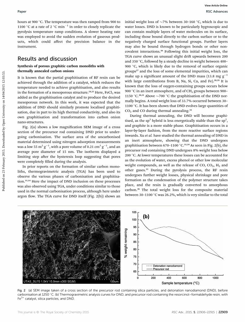
Fig. 2(a) shows a low magnication SEM image of a crosssection of the precursor rod containing DND prior to under-going carbonisation. The surface area of the uncarbonisedmaterial determined using nitrogen adsorption measurementswas a low 55 m2 g�1, with a pore volume of 0.21 cm3 g�1, and anaverage pore diameter of 15 nm. The isotherm displayed alimiting step aer the hysteresis loop suggesting that poreswere completely lled during the analysis.
In prior reports on the formation of similar carbon mono-liths, thermogravimetric analysis (TGA) has been used toobserve the various phases of carbonisation and graphitisa-tion.11,14 Here the impact of DND inclusion on these processeswas also observed using TGA, under conditions similar to thoseused in the normal carbonisation process, although here underargon ow. The TGA curve for DND itself (Fig. 2(b)) shows an
Fig. 2 (a) SEM image taken of a cross section of the precursor rod cocarbonisation at 1250 �C. (b) Thermogravimetric analysis curves for DND,Fe3+ catalyst, silica particles, and DND.
This journal is © The Royal Society of Chemistry 2015
initial weight loss of �7% between 30–160 �C, which is due towater losses. DND is known to be particularly hygroscopic andcan contain multiple layers of water molecules on its surface,including those bound directly to the carbon surface or to thenegatively charged surface functional groups. Further layersmay also be bound through hydrogen bonds or other non-covalent interactions.26 Following this initial weight loss, theTGA curve shows an unusual slight dri upwards between 200and 350 �C, followed by a steady decline in weight between 400–900 �C, which is likely due to the removal of surface organicgroups27 and the loss of some elemental impurities, which canmake up a signicant amount of the DND mass (13.8 mg g�1
with large contributions from B, Na, Si, Ca, and Fe).28,29 It isknown that the loss of oxygen-containing groups occurs below900 �C in an inert atmosphere, and of CHx groups between 900–1150 �C.30,31 Above �700 �C the graphitisation of the DND nor-mally begins. A total weight loss of 33.7% occurred between 30–1100 �C. It has been shown that DND evolves large quantities ofCO2 and CO during thermal annealing.32
During thermal annealing, the DND will become graphi-tised, as the sp3 hybrid is less energetically stable than the sp2,and graphite is a more stable phase. Graphitisation occurs in alayer-by-layer fashion, from the more reactive surface regionsinwards. Xu et al. have studied the thermal annealing of DND inan inert atmosphere, showing that the DND undergoesgraphitisation between 670–1100 �C.33,34 As seen in Fig. 2(b), theprecursor rod containing DND undergoes 8% weight loss below200 �C. At lower temperatures these losses can be accounted foras the evolution of water, excess phenol or other low molecularweight compounds, as well as the release of CO, CO2, H2 andother gases.35 During the pyrolysis process, the RF resinundergoes further weight losses, physical shrinkage and poreformation as the condensation of the polymer structure takesplace, and the resin is gradually converted to amorphouscarbon.36 The total weight loss for the composite materialbetween 30–1100 �C was 26.2%, which is very similar to the total
ntaining silica particles, and detonation nanodiamond (DND), beforeand precursor rod containing the resorcinol–formaldehyde resin, with
RSC Adv., 2015, 5, 22906–22915 | 22909
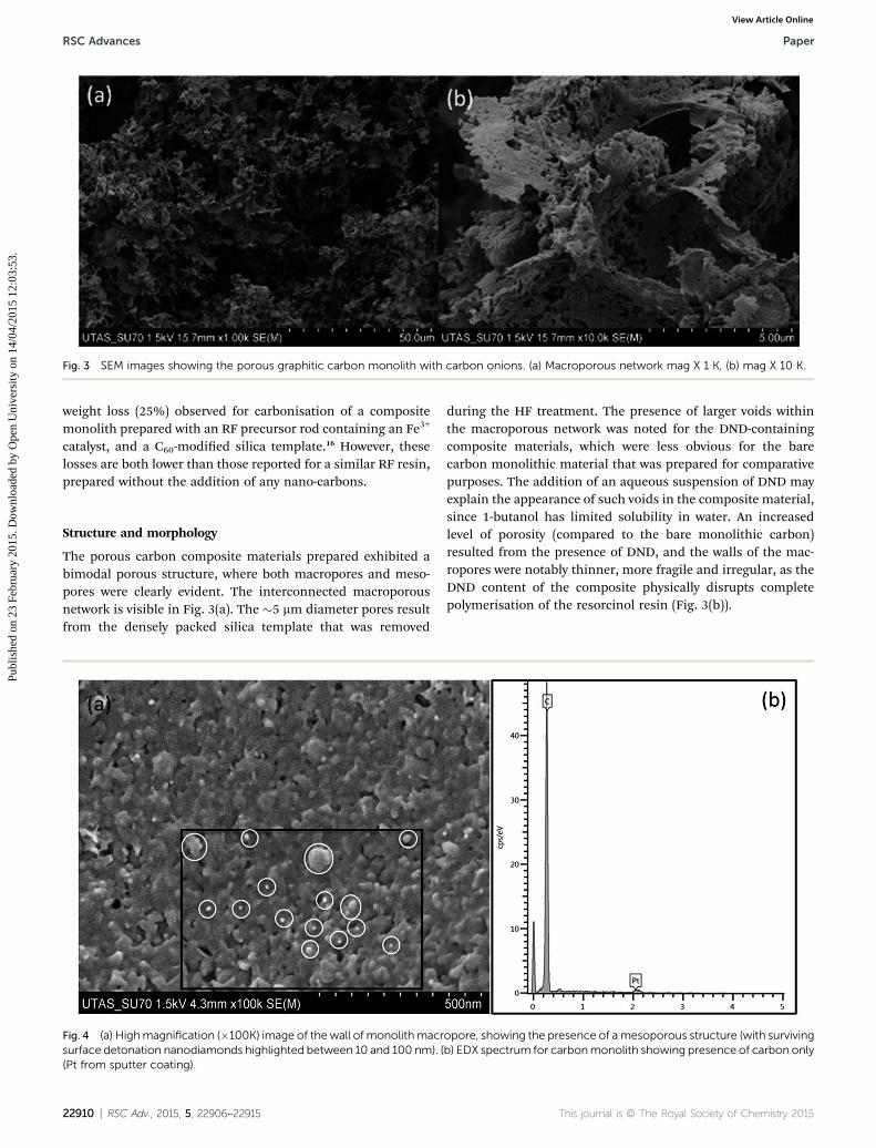
Fig. 3 SEM images showing the porous graphitic carbon monolith with carbon onions. (a) Macroporous network mag X 1 K, (b) mag X 10 K.
RSC Advances Paper
Publ
ishe
d on
23
Febr
uary
201
5. D
ownl
oade
d by
Ope
n U
nive
rsity
on
14/0
4/20
15 1
2:03
:53.
View Article Online
weight loss (25%) observed for carbonisation of a compositemonolith prepared with an RF precursor rod containing an Fe3+
catalyst, and a C60-modied silica template.16 However, theselosses are both lower than those reported for a similar RF resin,prepared without the addition of any nano-carbons.
Structure and morphology
The porous carbon composite materials prepared exhibited abimodal porous structure, where both macropores and meso-pores were clearly evident. The interconnected macroporousnetwork is visible in Fig. 3(a). The �5 mm diameter pores resultfrom the densely packed silica template that was removed
Fig. 4 (a) Highmagnification (�100K) image of the wall of monolithmacrsurface detonation nanodiamonds highlighted between 10 and 100 nm). ((Pt from sputter coating).
22910 | RSC Adv., 2015, 5, 22906–22915
during the HF treatment. The presence of larger voids withinthe macroporous network was noted for the DND-containingcomposite materials, which were less obvious for the barecarbon monolithic material that was prepared for comparativepurposes. The addition of an aqueous suspension of DND mayexplain the appearance of such voids in the composite material,since 1-butanol has limited solubility in water. An increasedlevel of porosity (compared to the bare monolithic carbon)resulted from the presence of DND, and the walls of the mac-ropores were notably thinner, more fragile and irregular, as theDND content of the composite physically disrupts completepolymerisation of the resorcinol resin (Fig. 3(b)).
opore, showing the presence of a mesoporous structure (with survivingb) EDX spectrum for carbonmonolith showing presence of carbon only
This journal is © The Royal Society of Chemistry 2015
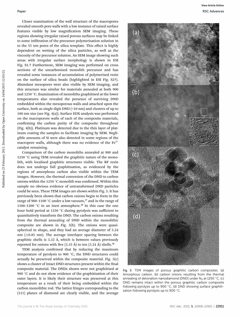
Fig. 5 TEM images of porous graphitic carbon composites. (a)Amorphous carbon, (b) carbon onions resulting from the thermalannealing of detonation nanodiamond (DND) under N2 at 1250 �C, (c)DND remains intact within the porous graphitic carbon compositefollowing pyrolysis up to 900 �C, (d) DND showing surface graphiti-sation following pyrolysis up to 900 �C.
Paper RSC Advances
Publ
ishe
d on
23
Febr
uary
201
5. D
ownl
oade
d by
Ope
n U
nive
rsity
on
14/0
4/20
15 1
2:03
:53.
View Article Online
Closer examination of the wall structure of the macroporesrevealed smooth pore walls with a low instance of raised surfacefeatures visible by low magnication SEM imaging. Theseregions showing irregular raised porous surfaces may be linkedto some inltration of the precursor polymerisation solution into the 55 nm pores of the silica template. This effect is highlydependent on wetting of the silica particles, as well as theviscosity of the precursor solution. An SEM image showing suchareas with irregular surface morphology is shown in ESIFig. S1.† Furthermore, SEM imaging was performed on crosssections of the uncarbonised monolith precursor and hasrevealed some instances of accumulation of polymerised resinon the surface of silica beads (highlighted in ESI Fig. S2†).Abundant mesopores were also visible by SEM imaging, andthis structure was similar for materials annealed at both 900and 1250 �C. Examination of monoliths graphitised at the lowertemperatures also revealed the presence of surviving DNDembedded within the mesoporous walls and attached upon thesurface, both as single digit DND (<10 nm) and clusters of up to100 nm size (see Fig. 4(a)). Surface EDX analysis was performedon the macroporore walls of each of the composite materials,conrming the carbon purity of the composite throughout(Fig. 4(b)). Platinum was detected due to the thin layer of plat-inum coating the samples to facilitate imaging by SEM. Negli-gible amounts of Si were also detected in some regions of themacropore walls, although there was no evidence of the Fe3+
catalyst remaining.Comparison of the carbon monoliths annealed at 900 and
1250 �C using TEM revealed the graphitic nature of the mono-lith, with localised graphitic structures visible. The RF resindoes not undergo full graphitisation, as evidenced by theregions of amorphous carbon also visible within the TEMimages. However, the thermal conversion of the DND to carbononions within the 1250 �Cmonolith was conrmed. Within thissample no obvious evidence of untransformed DND particlescould be seen. These TEM images are shown within Fig. 5. It haspreviously been shown that carbon onions begin to form in therange of 900–1100 �C under a low vacuum,37 and in the range of1100–1200 �C in an inert atmosphere.38 In this case the onehour hold period at 1250 �C during pyrolysis was sufficient toquantitatively transform the DND. The carbon onions resultingfrom the thermal annealing of DND within the monolithiccomposite are shown in Fig. 5(b). The onions were quasi-spherical in shape, and they had an average diameter of 5.24nm (�0.85 nm). The average interlayer spacing between thegraphitic shells is 3.32 �A, which is between values previouslyreported for onions with ve (3.35 �A) to ten (3.24 �A) shells.38
TEM analysis conrmed that by reducing the maximumtemperature of pyrolysis to 900 �C, the DND structures couldactually be preserved within the composite material. Fig. 5(c)shows a cluster of intact DND structures present within the nalcomposite material. The DNDs shown were not graphitised at900 �C and do not show evidence of the graphitisation of theirouter layers. It is likely their structure was preserved at thistemperature as a result of their being embedded within thecarbon monolithic rod. The lattice fringes corresponding to the(111) planes of diamond are clearly visible, and the average
This journal is © The Royal Society of Chemistry 2015 RSC Adv., 2015, 5, 22906–22915 | 22911

RSC Advances Paper
Publ
ishe
d on
23
Febr
uary
201
5. D
ownl
oade
d by
Ope
n U
nive
rsity
on
14/0
4/20
15 1
2:03
:53.
View Article Online
interlayer spacing measured on the DND within the compositewas 2.06 � 0.28�A. The average particle size as observed by TEMwas 11.4 � 0.9 nm, as expected based upon the specication ofthe commercial sample (5–15 nm particle diameter). However,some DND particles did show partial graphitisation at 900 �C,which agrees with work by Cebik et al., which demonstratedthat annealing DND in an inert atmosphere at 900–1000 �C canlead to the conversion of some of the surfaces of ND to layeredsp2 carbon.39 DND present at the surface level of the compositematerial would not experience the same environment as thoseparticles which were embedded in the rod during pyrolysis at900 �C, and so partial layer-by-layer conversion to sp2 carbonhas occurred, as visible in Fig. 5(d). Thus, careful control oftemperature of pyrolysis allows control of the nature of thenano-carbons present in the nal monolithic compositematerials.
Raman spectroscopy was applied to shed further light on thestructure of the monolithic composite materials. The disorderin graphite can give rise to several characteristic Raman peaks.40
The 800–2000 cm�1 region in the Raman spectrum showscommon features for all carbons. The G and D peaks are typi-cally around 1560 and 1360 cm�1 respectively, for visible
Fig. 6 Raman spectra for A – bare carbonmonolith (prepared withoutaddition of carbon nanoparticles for comparative purposes), B –carbon on carbon monolithic composite, and C – commercialgraphite. Both carbon monolithic materials underwent pyrolysis at1250 �C.
22912 | RSC Adv., 2015, 5, 22906–22915
excitation.41 The spectrum for the blank porous carbon mono-lith is also shown in Fig. 6(a). Three peaks were observed in theRaman spectrum for the monolithic composites containingcarbon onions (Fig. 6(b)). These three peaks are usually seen forcarbonaceous materials with both sp2 and sp3 bonds present.The G band appears at �1580 cm�1 and corresponds to the E2goptical mode in a two-dimensional network structure, alwaysseen for sp2 carbon materials. The D band is visible at �1335cm�1 and it is associated with disordered carbon,42 denoting aloss of hexagonal symmetry in the material (for highly orderedpyrolytic graphite, this peak is very small or even negligible, seeFig. 6(c) for comparison). The intensity of the D band to the Gband (R ¼ ID/IG) can be used to illustrate the degree of graphi-tisation in a material. Here, the blank carbon monolithicmaterial showed an R-value of 0.64, and the 1250 �C formedcomposite monolith gave a value of 0.37 (the R-value forcommercial graphite was 0.14), thus conrming the greatergraphitic nature of the carbon on carbon composite material.This supports the proposal that inclusion of the DND promoteslocalised graphitisation, both due to its inherent high thermalconductivity, and self-graphitisation during pyrolysis.
Temperature of pyrolysis is an important factor to considerhere, as the composite resin remains a predominantly disor-dered material following its carbonisation up to 1250 �C. The G0
band is seen to appear at �2680 cm�1 and typically appears forsp2 carbon materials resulting from a second order two phononprocess.43 These results conrm the presence of both graphiticand amorphous carbon in the carbon framework of the mono-lithic composites. Analysis by XPS further demonstrated theeffect of pyrolysis temperature on partial graphitisation of thecomposites (Fig. 7). A downshi in the binding energy wasobserved for the carbon core level (C 1s) spectral comparison ofmonoliths carbonised at 900 �C (285.5 � 0.05 eV) and 1250 �C(284.5 � 0.05 eV) under a nitrogen atmosphere. This observa-tion was similar to that reported by Xie et al. for the annealing ofDND at 900 and 1500 �C,44 and within studies by Krishnamurthyand co-workers.23,45 This shi in binding energy relates to the
Fig. 7 C 1s XPS spectra of carbon monoliths containing detonationnanodiamond which underwent pyrolysis at temperatures of 900 �Cand 1250 �C. Spectra were obtained in normal emission geometry at aphoton energy of 1486.6 eV.
This journal is © The Royal Society of Chemistry 2015

Table 1 Structural characteristics of carbon monolithic composites
MonolithSBET
a
(m2 g�1)Vp
a
(cm3 g�1)Porediameterb (nm)
Bare carbon monolith 115 � 8 0.33 � 0.05 11.7 � 0.8Carbon monolithwith carbon onions
214 � 17 0.35 � 0.04 10.5 � 3.9
a The Brunauer–Emmett–Teller (BET) method was used to calculatespecic surface areas. b The Barrett–Joyner–Halenda (BJH) methodwas used to calculate mesopore diameters from the adsorptionbranch of the isotherm.
Paper RSC Advances
Publ
ishe
d on
23
Febr
uary
201
5. D
ownl
oade
d by
Ope
n U
nive
rsity
on
14/0
4/20
15 1
2:03
:53.
View Article Online
material moving towards graphitisation as a function of thepyrolysis temperature. The binding energy of 284.5 eV for thecomposite that underwent pyrolysis at 1250 �C is slightly higherthan one for graphite (284.4 eV).30 Also evident in the 1250 �Cannealed sample, but not featured within the 900 �C sample,was the shake-up feature related to the p to p* transition ataround 290.8 � 0.05 eV, commonly seen in more graphitisedmaterials.
It is widely known that DND typically has a high concentra-tion of structural defects on its surface, which increases thesurface reactivity. Pyrolysis of the composites at 900 �Cproduced some hybrid nanocarbons combining the core prop-erties of ND, with the surface reactivity of sp2-based nano-carbons, as discussed above in relation to Fig. 5(d).46 Theproduction of hybrid nanocarbons is similar in effect toprevious work reported by Ostrovidova et al. where ND particleswere bonded by a graphite-like matrix in order to produce ahigh surface area porous nanodiamond composite press-moulded tablet for immobilisation of biomolecules.47
High-surface area carbon monoliths
The adsorption of nitrogen on the blank carbon monolithshowed a type IV isotherm, which is typical of mesoporousmaterials (Fig. 8(A)). Similarly, the carbon composite monolith(carbonised up to 1250 �C) also exhibited a type IV isotherm(Fig. 8(B)). The initial region of the isotherm where an increasein adsorption followed by the knee is the point at whichmonolayer adsorption is preceded by multilayer adsorption.The presence of the hysteresis loop is indicative of capillarycondensation within the mesopores. The hysteresis loop is typeH3, which is associated with the presence of slit-like pores, andthe limiting step (at high relative pressure) seen for manymesoporous sorbents of isotherm type IV is not present in a typeH3 hysteresis loop. This suggests that complete pore lling maynot have occurred.48 The material does not show a sharpcondensation/evaporation step, which typically characterises a
Fig. 8 Nitrogen adsorption–desorption isotherms for A – bare carbonmonolith (prepared without the addition of carbon nanoparticles forcomparative purposes) and B – carbon on carbon monolithiccomposite containing carbon onions.
This journal is © The Royal Society of Chemistry 2015
narrow pore size distribution. Therefore, these materials likelyexhibit a wide mesopore size distribution with irregular poreshapes. The steep desorption region in the hysteresis loop isassociated with the (forced) closure of the loop due to the so-called tensile strength effect. Closure of the hysteresis loop atP/P0 � 0.4 indicates that the mesopores were relatively small insize. Estimated mesopore diameters for both materials were inagreement, with the Barrett–Joyner–Halenda (BJH) methodapplied49 to nd mesopore diameters of 11.7 � 0.8 nm and 10.5� 3.9 nm, for the blank carbon monolith and monolithiccomposite, respectively (see Table 1). The carbon monolithiccomposite had a slightly greater mesopore volume of 0.35 �0.04 cm3 g�1 compared to 0.33 � 0.05 cm3 g�1 for the blankmonolith. The addition of DND appears to have increased theprevalence of mesopores with smaller diameters. Signicantlythen it is clear that the addition of DND to the carbon monolithcan be used to affect both the macroporous and mesoporousstructure, as evidenced by both BET, and SEM images discussedpreviously (Fig. 3). The average BET surface area calculated forthe monolithic composite at P/P0 from 0.05 to 0.30 was 214 m2
g�1, nearly twice which obtained for the bare carbon monolith,which was 115 m2 g�1. The higher surface area in the compositematerial is due to the increased macro and meso-porosity, andfrom the surface area contribution from the nano-carbonmaterials embedded in the carbon skeleton, which are knownto display high surface areas.50 This represents a signicantincrease, which if related to the concentration of DND added,could provide a unique method for control of this importantparameter.
Conclusions
New bimodal carbon on carbon monolithic composites weresuccessfully prepared by embedding DND in a resorcinolformaldehyde precursor mixture, containing Fe3+ as a catalystfor localised graphitisation, and silica gel as a hard template.Pyrolysis cycles reached a maximum temperature of 1250 �C,which was sufficiently high enough to result in the fullgraphitisation of the DND precursor, forming quasi-sphericalcarbon onions within the monolith, which had an averagediameter of 5.24 nm. The inclusion of DND increased thegraphitisation of the composite material, which contained bothsp2 and sp3 carbon phases following pyrolysis. Both the
RSC Adv., 2015, 5, 22906–22915 | 22913

RSC Advances Paper
Publ
ishe
d on
23
Febr
uary
201
5. D
ownl
oade
d by
Ope
n U
nive
rsity
on
14/0
4/20
15 1
2:03
:53.
View Article Online
macroporous network and mesopores were affected by theaddition of DND, and the BET surface area and pore volumewere increased in comparison with a blank carbon monolith. Itwas also shown that the DND could be preserved within thecomposite by reducing the temperature of pyrolysis, thusdemonstrating the ability to easily control nano-carbonsynthesis within a monolithic composite. Carbon monolithiccomposites with carbon onions are suitable for application in anumber of areas such as electrode materials, chromatographicapplications and extraction processes for larger moleculesincluding organic pollutants or biomolecules.
To the best of the authors' knowledge, this is the rst report ofthe controlled production of carbon onions from DND withinsuch a carbon monolithic composite. It demonstrates that thetype of nano-carbons present in the nal monolithic compositecan be tuned, simply by controlling the temperature of pyrolysis.
Acknowledgements
The authors thank the Australian Research Council (Discoverygrant DP110102046) for research funding. We would like tothank Mrs Heather Davies, Dr Brendan Twamley, Dr KarstenGoemann and Dr Sandrin Feig for their technical support andassistance with electron microscopy imaging.
Notes and references
1 P. Colombo, Science, 2008, 322, 381–383.2 D.-W. Wang, F. Li, M. Liu, G. Q. Lu and H.-M. Cheng, Angew.Chem., Int. Ed., 2008, 47, 373–376.
3 F. U. Ruo-Wen, L. I. Zheng-Hui, L. Ye-Ru, L. I. Feng, X. U. Feiand W. U. Ding-Cai, New Carbon Mater., 2011, 26, 171–179.
4 M. Sevilla and A. B. Fuertes, Energy Environ. Sci., 2011, 4,1765–1771.
5 G.-P. Hao, W.-C. Li, D. Qian and A.-H. Lu, Adv. Mater., 2010,22, 853–857.
6 V. K. Gupta and T. A. Saleh, Environ. Sci. Pollut. Res., 2013, 20,2828–2843.
7 L. Chuenchom, R. Kraehnert and B. M. Smarsly, So Matter,2012, 8, 10801–10812.
8 A. D. Roberts, X. Li and H. Zhang, Chem. Soc. Rev., 2014, 43,4341–4356.
9 S. Dutta, A. Bhaumik and K. C.-W. Wu, Energy Environ. Sci.,2014, 7, 3574–3592.
10 C. Liang, S. Dai and G. Guiochon, Anal. Chem., 2003, 75,4904–4912.
11 A. H. Eltmimi, L. Barron, A. Rafferty, J. P. Hanrahan,O. Fedyanina, E. Nesterenko, P. N. Nesterenko andB. Paull, J. Sep. Sci., 2010, 33, 1231–1243.
12 V. Ruiz, C. Blanco, R. Santamarıa, J. M. Ramos-Fernandez,M. Martınez-Escandell, A. Sepulveda-Escribano andF. Rodrıguez-Reinoso, Carbon, 2009, 47, 195–200.
13 X. He, K. B. Male, P. N. Nesterenko, D. Brabazon, B. Paulland J. H. T. Luong, ACS Appl. Mater. Interfaces, 2013, 5,8796–8804.
14 Z. Wang, F. Li, N. S. Ergang and A. Stein, Chem. Mater., 2006,18, 5543–5553.
22914 | RSC Adv., 2015, 5, 22906–22915
15 L. Qiu, J. Z. Liu, S. L. Y. Chang, Y. Wu and D. Li, Nat.Commun., 2012, 3, 1241–1247.
16 X. He, E. P. Nesterenko, P. N. Nesterenko, D. Brabazon,L. Zhou, J. D. Glennon, J. H. T. Luong and B. Paull, ACSAppl. Mater. Interfaces, 2013, 5, 8572–8580.
17 M. S. Mauter and M. Elimelech, Environ. Sci. Technol., 2008,42, 5843–5859.
18 M. B. Seymour, C. Su, Y. Gao, Y. Lu and Y. Li, J. Nanopart.Res., 2012, 14, 1087.
19 E. K. Chow, X.-Q. Zhang, M. Chen, R. Lam, E. Robinson,H. Huang, D. Schaffer, E. Osawa, A. Goga and D. Ho, Sci.Transl. Med., 2011, 3, 73ra21.
20 T. J. Merkel and J. M. DeSimone, Sci. Transl. Med., 2011, 3,73ps8.
21 V. L. Kuznetsov, A. L. Chuvilin, Y. V. Butenko, I. Y. Mal'kovand V. M. Titov, Chem. Phys. Lett., 1994, 222, 343–348.
22 D. Pech, M. Brunet, H. Durou, P. Huang, V. Mochalin,Y. Gogotsi, P.-L. Taberna and P. Simon, Nat. Nanotechnol.,2010, 5, 651–654.
23 Y. V. Butenko, S. Krishnamurthy, A. K. Chakraborty,V. L. Kuznetsov, V. R. Dhanak, M. R. C. Hunt and L. Siller,Phys. Rev. B: Condens. Matter Mater. Phys., 2005, 71,075420.
24 A. Oya and H. J. Marsh, J. Mater. Sci., 1982, 17, 309–322.25 M. Sevilla and A. B. Fuertes, Carbon, 2006, 44, 468–474.26 S. S. Batsanov, E. V. Lesnikov, D. A. Dan'kin and
D. M. Balakhanov, Appl. Phys. Lett., 2014, 104, 133105.27 W.-W. Zheng, Y.-H. Hsieh, Y.-C. Chiu, S.-J. Cai, C.-L. Cheng
and C. Chen, J. Mater. Chem., 2009, 19, 8432–8441.28 D. P. Mitev, A. T. Townsend, B. Paull and P. N. Nesterenko, J.
Mater. Sci., 2014, 49, 3573–3591.29 D. P. Mitev, A. T. Townsend, B. Paull and P. N. Nesterenko,
Carbon, 2013, 60, 326–334.30 Y. V. Butenko, V. L. Kuznetsov, E. A. Paukshtis,
A. I. Stadnichenko, I. N. Mazov, S. I. Moseenkov,A. I. Boronin and S. V. Kosheev, Fullerenes, Nanotubes,Carbon Nanostruct., 2006, 14, 557–564.
31 V. Mochalin, A. Osswald and Y. Gogotsi, Chem. Mater., 2009,21, 273–279.
32 K. W. Lin, C. L. Cheng and H. C. Chang, Chem. Mater., 1998,10, 1735–1737.
33 N. S. Xu, J. Chen and S. Z. Deng, Diamond Relat. Mater., 2002,11, 249–256.
34 J. Chen, S. Z. Deng, J. Chen, Z. X. Yu and N. S. Xu, Appl. Phys.Lett., 1999, 74, 3651–3653.
35 T. H. Ko, W. S. Kuo and Y. R. Lu, Polym. Compos., 2000, 21,96–103.
36 T. H. Ko, W. S. Kuo and Y. H. Chang, J. Appl. Polym. Sci.,2001, 81, 1084–1089.
37 Q. Zou, M. Wang, Y. Li, Y. Zhao and L. Zou, Sci. China, Ser. E:Technol. Sci., 2009, 52, 3683–3689.
38 Z. Qiao, J. Li, N. Zhao, C. Shi and P. Nash, Scr. Mater., 2006,54, 225–229.
39 J. Cebik, J. K. McDonough, F. Peerally, R. Medrano, I. Neitzel,Y. Gogotsi and S. Osswald, Nanotechnology, 2013, 24, 205703.
40 F. Tuinstra and J. L. Koenig, J. Chem. Phys., 1970, 53, 1126–1130.
This journal is © The Royal Society of Chemistry 2015

Paper RSC Advances
Publ
ishe
d on
23
Febr
uary
201
5. D
ownl
oade
d by
Ope
n U
nive
rsity
on
14/0
4/20
15 1
2:03
:53.
View Article Online
41 A. C. Ferrari and J. Robertson, Philos. Trans. R. Soc. London,Ser. A, 2004, 362, 2477–2512.
42 A. C. Ferrari and J. Robertson, Phys. Rev. B: Condens. MatterMater. Phys., 2000, 61, 14095–14107.
43 X. He, L. Zhou, E. P. Nesterenko, P. N. Nesterenko, B. Paull,J. O. Omamogho, J. D. Glennon and J. H. Luong, Anal. Chem.,2012, 84, 2351–2357.
44 F. Y. Xie, W. G. Xie, L. Gong, W. H. Zhang, S. H. Chen,Q. Z. Zhang and J. Chen, Surf. Interface Anal., 2010, 42,1514–1518.
45 S. Krishnamurthy, Y. V. Butenko, V. R. Dhanak,M. R. C. Hunt and L. Siller, Carbon, 2013, 52, 145–149.
This journal is © The Royal Society of Chemistry 2015
46 T. Petit, J.-C. Arnault, H. A. Girard, M. Sennour andP. Bergonzo, Phys. Rev. B: Condens. Matter Mater. Phys.,2011, 84, 233407.
47 G. U. Ostrovidova, A. V. Makeev, A. V. Biryukov andS. K. Gordeev, Mater. Sci. Eng., 2003, 23, 377–381.
48 S. Lowell, J. E. Shields, M. A. Thomas and M. Thommes, inCharacterization of Porous Solids and Powders: Surface Area,Pore Size and Density, Kluwer Academic Publishers,London, 2004.
49 E. P. Barrett, L. G. Joyner and P. P. Halenda, J. Am. Chem.Soc., 1951, 73, 373–380.
50 J. K. McDonough and Y. Gogotsi, Electrochem. Soc. Interface,2013, 3, 61–66.
RSC Adv., 2015, 5, 22906–22915 | 22915