thermal treatment - · pdf filepage rotors detail on ctid 700 non-contractual drawings and...
TRANSCRIPT
Thermal treatment
Page �
Non-c
ontr
actu
al d
raw
ings
and p
ictu
res
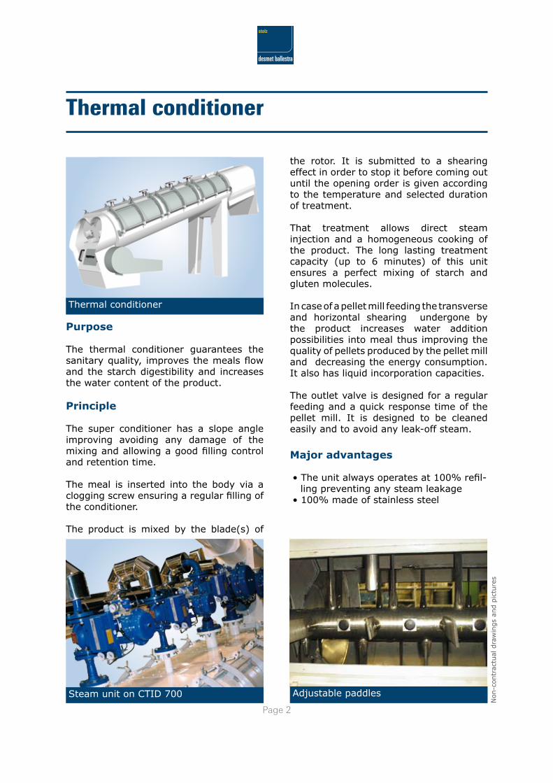
Thermal conditioner
Adjustable paddles
the rotor. It is submitted to a shearing effect in order to stop it before coming out until the opening order is given according to the temperature and selected duration of treatment.
That treatment allows direct steam injection and a homogeneous cooking of the product. The long lasting treatment capacity (up to 6 minutes) of this unit ensures a perfect mixing of starch and gluten molecules.
In case of a pellet mill feeding the transverse and horizontal shearing undergone by the product increases water addition possibilities into meal thus improving the quality of pellets produced by the pellet mill and decreasing the energy consumption. It also has liquid incorporation capacities.
The outlet valve is designed for a regular feeding and a quick response time of the pellet mill. It is designed to be cleaned easily and to avoid any leak-off steam.
Major advantages
• The unit always operates at 100% refil-ling preventing any steam leakage
• 100% made of stainless steel
Purpose
The thermal conditioner guarantees the sanitary quality, improves the meals flow and the starch digestibility and increases the water content of the product.
Principle
The super conditioner has a slope angle improving avoiding any damage of the mixing and allowing a good filling control and retention time.
The meal is inserted into the body via a clogging screw ensuring a regular filling of the conditioner.
The product is mixed by the blade(s) of
Thermal conditioner
Steam unit on CTID 700
Page �
Non-c
ontr
actu
al d
raw
ings
and p
ictu
res
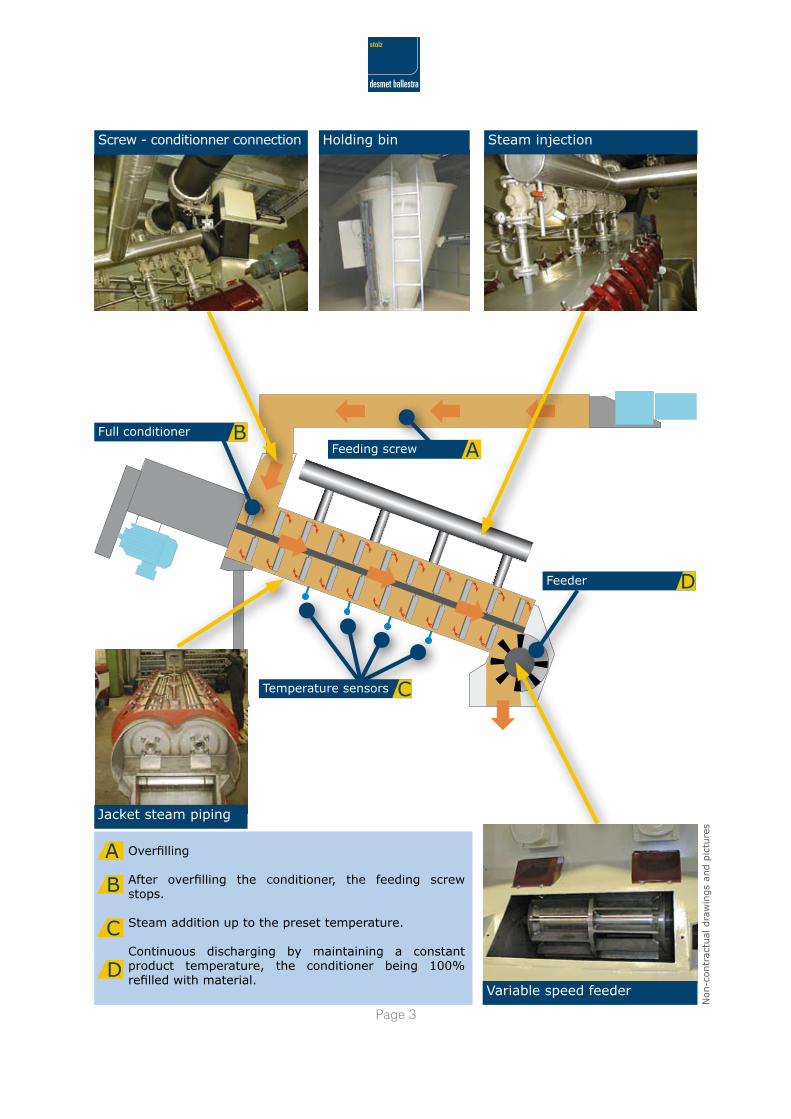
Holding bin Steam injectionScrew - conditionner connection
Jacket steam piping
Variable speed feeder
Feeding screw AFull conditioner B
Temperature sensors C
Feeder D
Overfilling
After overfilling the conditioner, the feeding screw stops.
Steam addition up to the preset temperature.
Continuous discharging by maintaining a constant product temperature, the conditioner being 100% refilled with material.
A
B
C
D
Page �
Non-c
ontr
actu
al d
raw
ings
and p
ictu
res
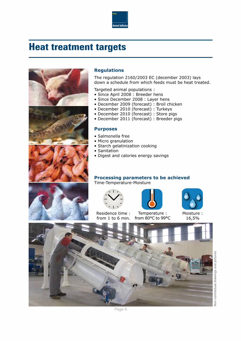
Heat treatment targets
Regulations
The regulation 2160/2003 EC (december 2003) lays down a schedule from which feeds must be heat treated.
Targeted animal populations :• Since April 2008 : Breeder hens• Since December 2008 : Layer hens• December 2009 (forecast) : Broil chicken• December 2010 (forecast) : Turkeys• December 2010 (forecast) : Store pigs• December 2011 (forecast) : Breeder pigs
Purposes
• Salmonella free• Micro granulation• Starch gelatinization cooking• Sanitation• Digest and calories energy savings
Processing parameters to be achievedTime-Temperature-Moisture
Residence time :from 1 to 6 min.
Temperature :from 80°C to 99°C
Moisture :16,5%
Page �
Non-c
ontr
actu
al d
raw
ings
and p
ictu
res
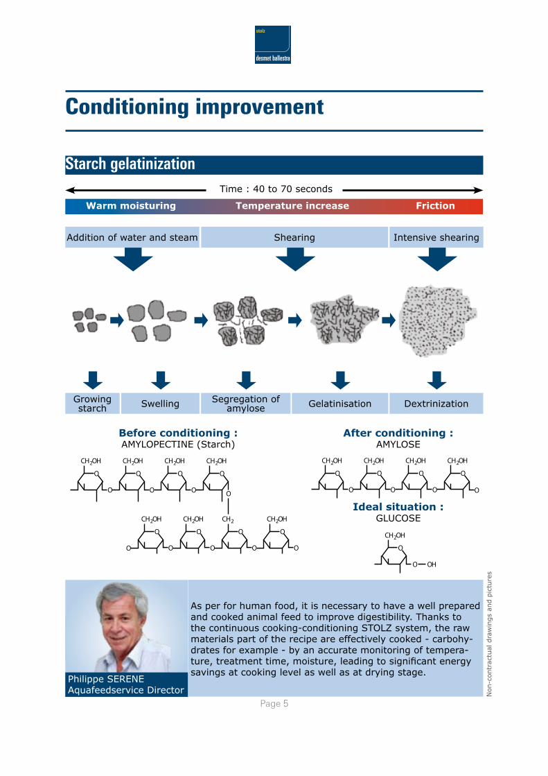
Conditioning improvement
Starch gelatinization
Philippe SERENEAquafeedservice Director
Before conditioning : AMYLOPECTINE (Starch)
After conditioning :AMYLOSE
Ideal situation :GLUCOSE
Time : 40 to 70 seconds
Warm moisturing Temperature increase Friction
Growing starch Swelling Segregation of
amylose Gelatinisation Dextrinization
Addition of water and steam Shearing Intensive shearing
As per for human food, it is necessary to have a well prepared and cooked animal feed to improve digestibility. Thanks to the continuous cooking-conditioning STOLZ system, the raw materials part of the recipe are effectively cooked - carbohy-drates for example - by an accurate monitoring of tempera-ture, treatment time, moisture, leading to significant energy savings at cooking level as well as at drying stage.
CH2OH
O
O
CH2OH
O
O
CH2OH
O
O
CH2OH
O
O
CH2OH
O
O
CH2OH
O
OO
CH2
O
O
CH2OH
O
O
CH2OH
O
O OH
CH2OH
O
O
CH2OH
O
O
CH2OH
O
O O
CH2OH
O
Page �
Non-c
ontr
actu
al d
raw
ings
and p
ictu
res
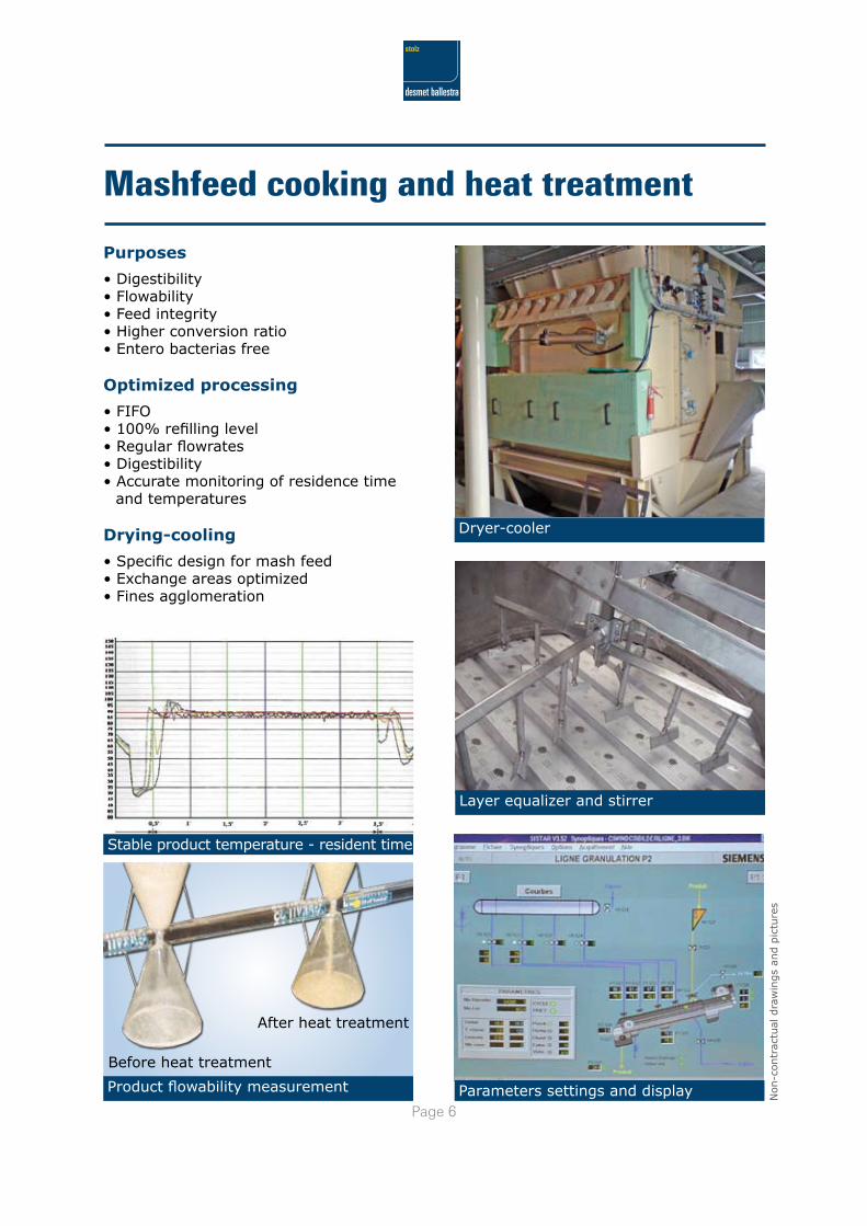
Mashfeed cooking and heat treatment
Parameters settings and display
Stable product temperature - resident time
Purposes
• Digestibility• Flowability• Feed integrity• Higher conversion ratio• Entero bacterias free
Optimized processing
• FIFO• 100% refilling level• Regular flowrates• Digestibility• Accurate monitoring of residence time
and temperatures
Drying-cooling
• Specific design for mash feed• Exchange areas optimized• Fines agglomeration
Product flowability measurement
Before heat treatment
After heat treatment
Layer equalizer and stirrer
Dryer-cooler
Page �
Non-c
ontr
actu
al d
raw
ings
and p
ictu
res
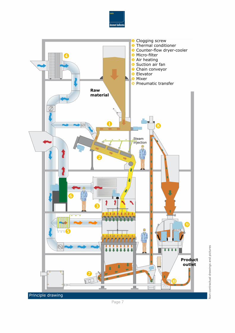
Principle drawing
Raw material
Product outlet
Steaminjection
u Clogging screwv Thermal conditionerw Counter-flow dryer-coolerx Micro-filtery Air heatingz Suction air fan{ Chain conveyor| Elevator} Mixer~ Pneumatic transfer
Page �
Non-c
ontr
actu
al d
raw
ings
and p
ictu
res
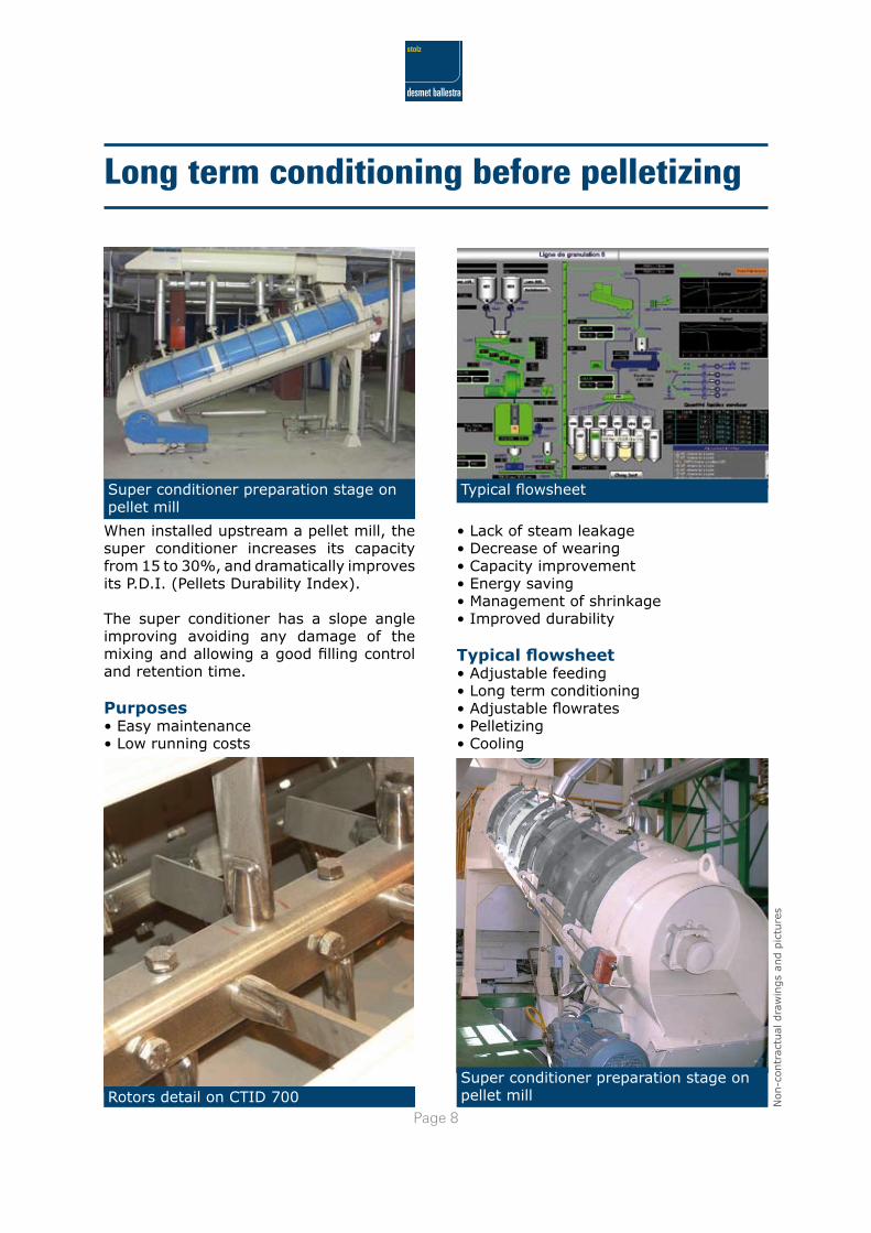
Rotors detail on CTID 700Super conditioner preparation stage on pellet mill
Long term conditioning before pelletizing
When installed upstream a pellet mill, the super conditioner increases its capacity from 15 to 30%, and dramatically improves its P.D.I. (Pellets Durability Index).
The super conditioner has a slope angle improving avoiding any damage of the mixing and allowing a good filling control and retention time.
Purposes• Easy maintenance• Low running costs
Super conditioner preparation stage on pellet mill
Typical flowsheet
• Lack of steam leakage• Decrease of wearing• Capacity improvement• Energy saving• Management of shrinkage• Improved durability
Typical flowsheet• Adjustable feeding• Long term conditioning• Adjustable flowrates• Pelletizing• Cooling
Page �
Non-c
ontr
actu
al d
raw
ings
and p
ictu
res
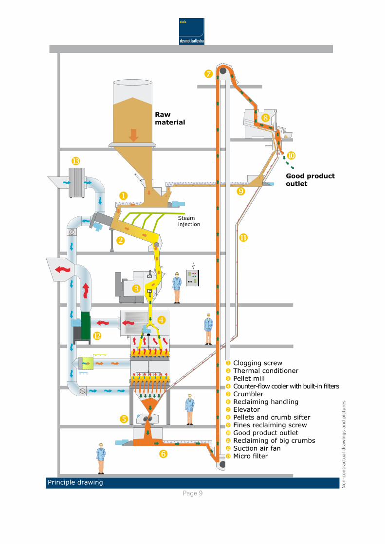
u Clogging screwv Thermal conditionerw Pellet millx Counter-flow cooler with built-in filtersy Crumblerz Reclaiming handling{ Elevator| Pellets and crumb sifter} Fines reclaiming screw~ Good product outlet~ Reclaiming of big crumbs~ Suction air fan~ Micro filter
Good product outlet
Raw material
Steaminjection
Principle drawing
Page 10
Non-c
ontr
actu
al d
raw
ings
and p
ictu
res
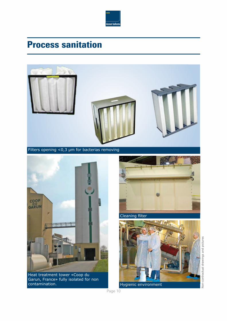
Process sanitation
Filters opening <0,3 µm for bacterias removing
Cleaning filter
Heat treatment tower «Coop du Garun, France» fully isolated for non contamination. Hygienic environment
Page 11
Non-c
ontr
actu
al d
raw
ings
and p
ictu
res
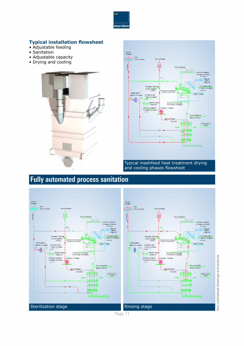
Typical installation flowsheet• Adjustable feeding• Sanitation• Adjustable capacity• Drying and cooling
Fully automated process sanitation
Typical mashfeed heat treatment drying and cooling phases flowsheet
Sterilization stage Rinsing stage
Page 1�
Non-c
ontr
actu
al d
raw
ings
and p
ictu
res
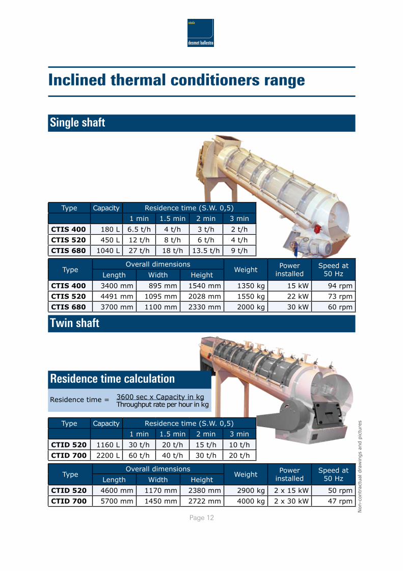
Inclined thermal conditioners range
Single shaft
Twin shaft
Type Capacity Residence time (S.W. 0,5)
1 min 1.5 min 2 min 3 min
CTIS 400 180 L 6.5 t/h 4 t/h 3 t/h 2 t/h
CTIS 520 450 L 12 t/h 8 t/h 6 t/h 4 t/h
CTIS 680 1040 L 27 t/h 18 t/h 13.5 t/h 9 t/h
Residence time calculation
Residence time = 3600 sec x Capacity in kg
Throughput rate per hour in kg
TypeOverall dimensions
Weight Power installed
Speed at 50 HzLength Width Height
CTIS 400 3400 mm 895 mm 1540 mm 1350 kg 15 kW 94 rpm
CTIS 520 4491 mm 1095 mm 2028 mm 1550 kg 22 kW 73 rpm
CTIS 680 3700 mm 1100 mm 2330 mm 2000 kg 30 kW 60 rpm
TypeOverall dimensions
Weight Power installed
Speed at 50 HzLength Width Height
CTID 520 4600 mm 1170 mm 2380 mm 2900 kg 2 x 15 kW 50 rpm
CTID 700 5700 mm 1450 mm 2722 mm 4000 kg 2 x 30 kW 47 rpm
Type Capacity Residence time (S.W. 0,5)
1 min 1.5 min 2 min 3 min
CTID 520 1160 L 30 t/h 20 t/h 15 t/h 10 t/h
CTID 700 2200 L 60 t/h 40 t/h 30 t/h 20 t/h
Page 1�
Non-c
ontr
actu
al d
raw
ings
and p
ictu
res
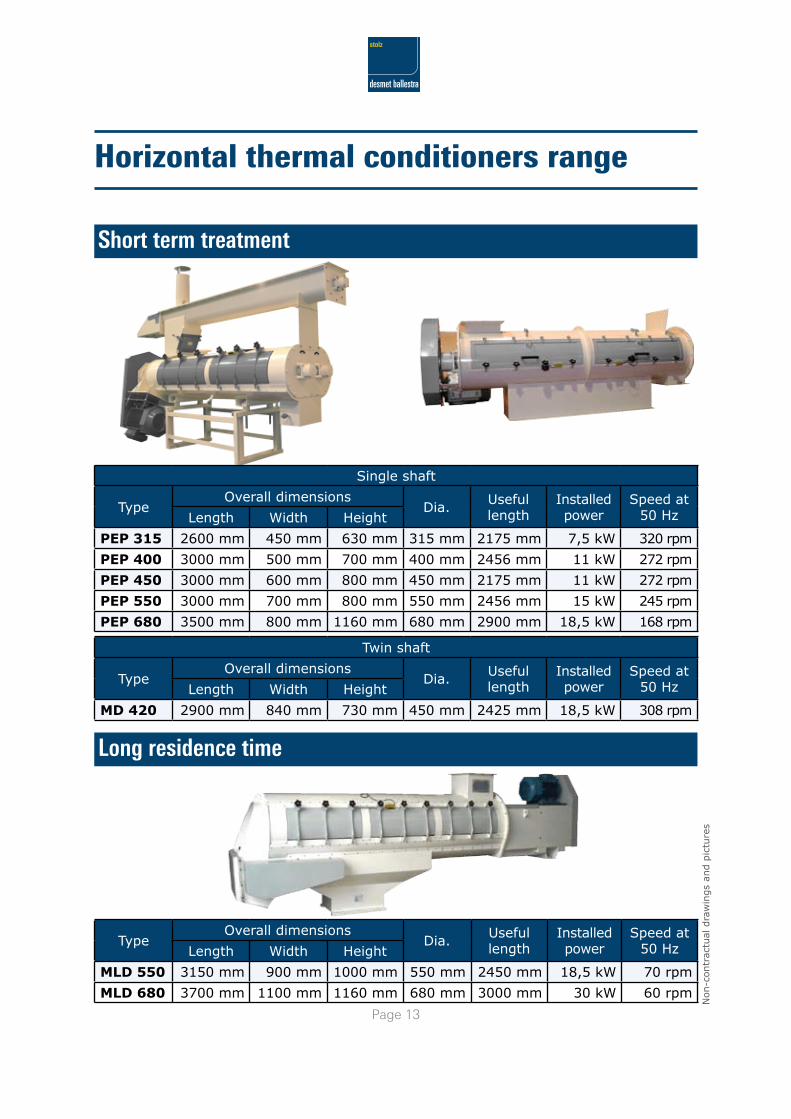
Horizontal thermal conditioners range
Short term treatment
Long residence time
TypeOverall dimensions
Dia. Useful length
Installed power
Speed at 50 HzLength Width Height
MLD 550 3150 mm 900 mm 1000 mm 550 mm 2450 mm 18,5 kW 70 rpm
MLD 680 3700 mm 1100 mm 1160 mm 680 mm 3000 mm 30 kW 60 rpm
Single shaft
TypeOverall dimensions
Dia. Useful length
Installed power
Speed at 50 HzLength Width Height
PEP 315 2600 mm 450 mm 630 mm 315 mm 2175 mm 7,5 kW 320 rpm
PEP 400 3000 mm 500 mm 700 mm 400 mm 2456 mm 11 kW 272 rpm
PEP 450 3000 mm 600 mm 800 mm 450 mm 2175 mm 11 kW 272 rpm
PEP 550 3000 mm 700 mm 800 mm 550 mm 2456 mm 15 kW 245 rpm
PEP 680 3500 mm 800 mm 1160 mm 680 mm 2900 mm 18,5 kW 168 rpm
Twin shaft
TypeOverall dimensions
Dia. Useful length
Installed power
Speed at 50 HzLength Width Height
MD 420 2900 mm 840 mm 730 mm 450 mm 2425 mm 18,5 kW 308 rpm
Page 1�
Non-c
ontr
actu
al d
raw
ings
and p
ictu
res
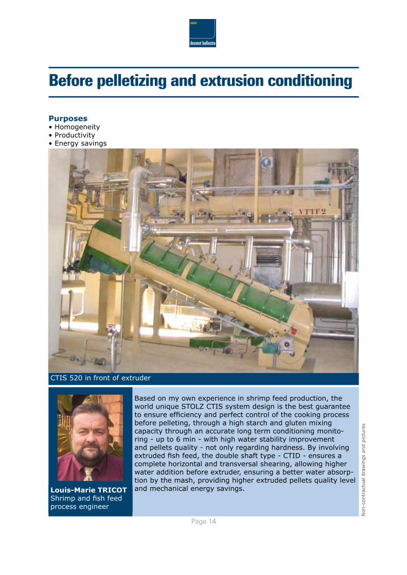
Before pelletizing and extrusion conditioning
Purposes• Homogeneity• Productivity• Energy savings
CTIS 520 in front of extruder
Based on my own experience in shrimp feed production, the world unique STOLZ CTIS system design is the best guarantee to ensure efficiency and perfect control of the cooking process before pelleting, through a high starch and gluten mixing capacity through an accurate long term conditioning monito-ring - up to 6 min - with high water stability improvement and pellets quality - not only regarding hardness. By involving extruded fish feed, the double shaft type - CTID - ensures a complete horizontal and transversal shearing, allowing higher water addition before extruder, ensuring a better water absorp-tion by the mash, providing higher extruded pellets quality level and mechanical energy savings.Louis-Marie TRICOT
Shrimp and fish feed process engineer
Page 1�
Non-c
ontr
actu
al d
raw
ings
and p
ictu
res
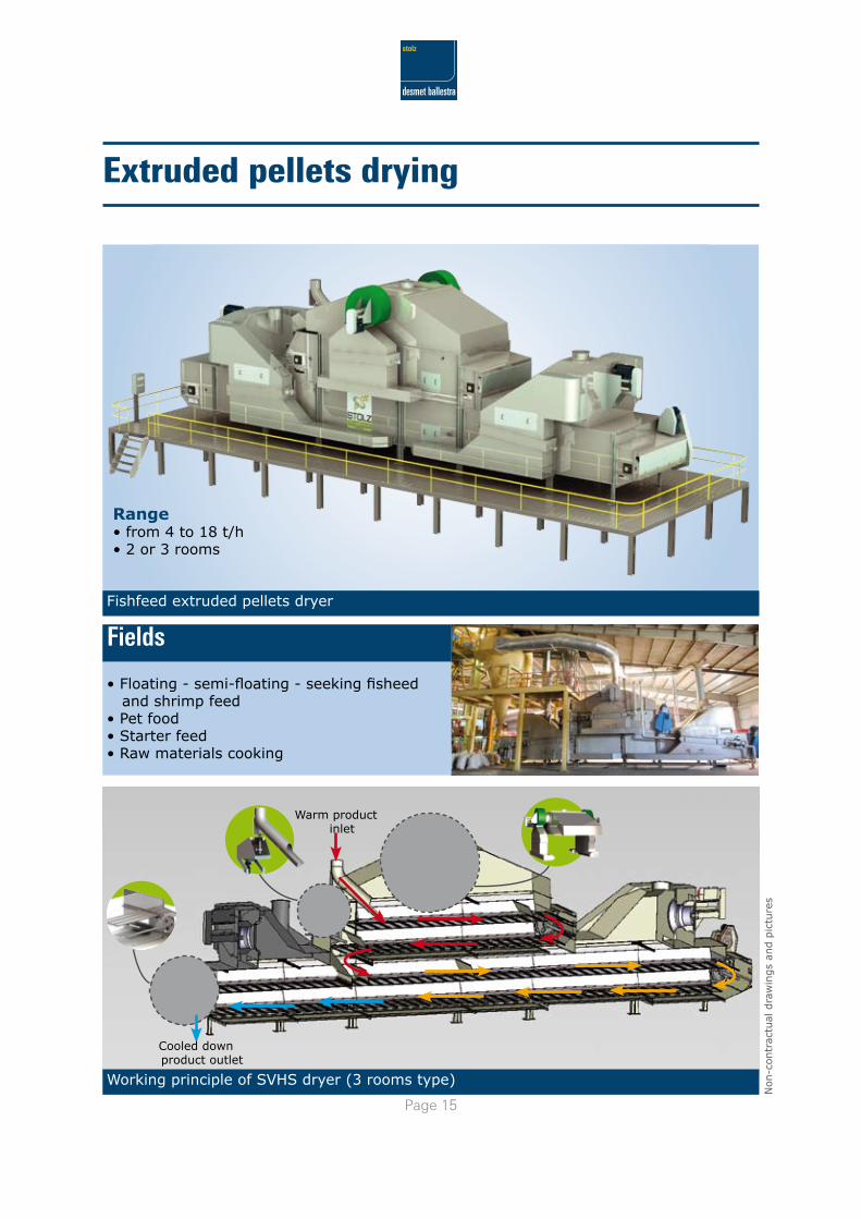
Extruded pellets drying
Fishfeed extruded pellets dryer
Range• from 4 to 18 t/h• 2 or 3 rooms
• Floating - semi-floating - seeking fisheed and shrimp feed• Pet food• Starter feed• Raw materials cooking
Fields
Working principle of SVHS dryer (3 rooms type)
Warm product inlet
Cooled down product outlet
Page 1�
Non-c
ontr
actu
al d
raw
ings
and p
ictu
res
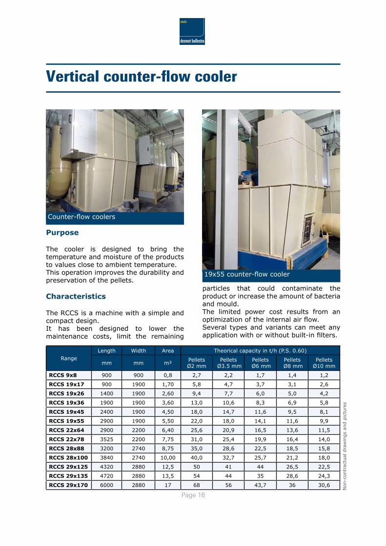
Purpose
The cooler is designed to bring the temperature and moisture of the products to values close to ambient temperature.This operation improves the durability and preservation of the pellets.
Characteristics
The RCCS is a machine with a simple and compact design.It has been designed to lower the maintenance costs, limit the remaining
RangeLength Width Area Theorical capacity in t/h (P.S. 0.60)
mm mm m² PelletsØ2 mm
Pellets Ø3.5 mm
Pellets Ø6 mm
Pellets Ø8 mm
Pellets Ø10 mm
RCCS 9x8 900 900 0,8 2,7 2,2 1,7 1,4 1,2
RCCS 19x17 900 1900 1,70 5,8 4,7 3,7 3,1 2,6
RCCS 19x26 1400 1900 2,60 9,4 7,7 6,0 5,0 4,2
RCCS 19x36 1900 1900 3,60 13,0 10,6 8,3 6,9 5,8
RCCS 19x45 2400 1900 4,50 18,0 14,7 11,6 9,5 8,1
RCCS 19x55 2900 1900 5,50 22,0 18,0 14,1 11,6 9,9
RCCS 22x64 2900 2200 6,40 25,6 20,9 16,5 13,6 11,5
RCCS 22x78 3525 2200 7,75 31,0 25,4 19,9 16,4 14,0
RCCS 28x88 3200 2740 8,75 35,0 28,6 22,5 18,5 15,8
RCCS 28x100 3840 2740 10,00 40,0 32,7 25,7 21,2 18,0
RCCS 29x125 4320 2880 12,5 50 41 44 26,5 22,5
RCCS 29x135 4720 2880 13,5 54 44 35 28,6 24,3
RCCS 29x170 6000 2880 17 68 56 43,7 36 30,6
particles that could contaminate the product or increase the amount of bacteria and mould.The limited power cost results from an optimization of the internal air flow. Several types and variants can meet any application with or without built-in filters.
Vertical counter-flow cooler
Counter-flow coolers
19x55 counter-flow cooler
Page 1�
Non-c
ontr
actu
al d
raw
ings
and p
ictu
res
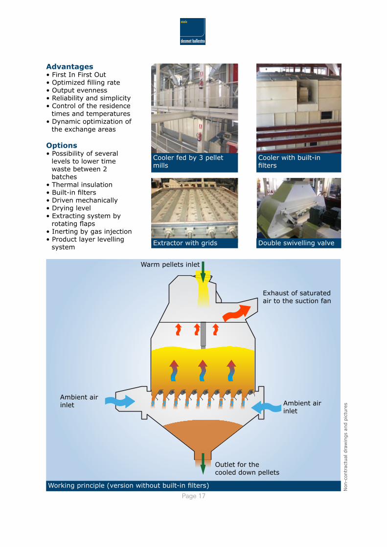
Exhaust of saturated air to the suction fan
Ambient air inlet Ambient air
inlet
Outlet for the cooled down pellets
Cooler with built-in filters
Working principle (version without built-in filters)
Advantages• First In First Out• Optimized filling rate• Output evenness• Reliability and simplicity• Control of the residence
times and temperatures• Dynamic optimization of
the exchange areas
Options• Possibility of several
levels to lower time waste between 2 batches
• Thermal insulation• Built-in filters• Driven mechanically• Drying level• Extracting system by rotating flaps
• Inerting by gas injection• Product layer levelling
system
Cooler fed by 3 pellet mills
Extractor with grids Double swivelling valve
Warm pellets inlet
Page 1�
Non-c
ontr
actu
al d
raw
ings
and p
ictu
res
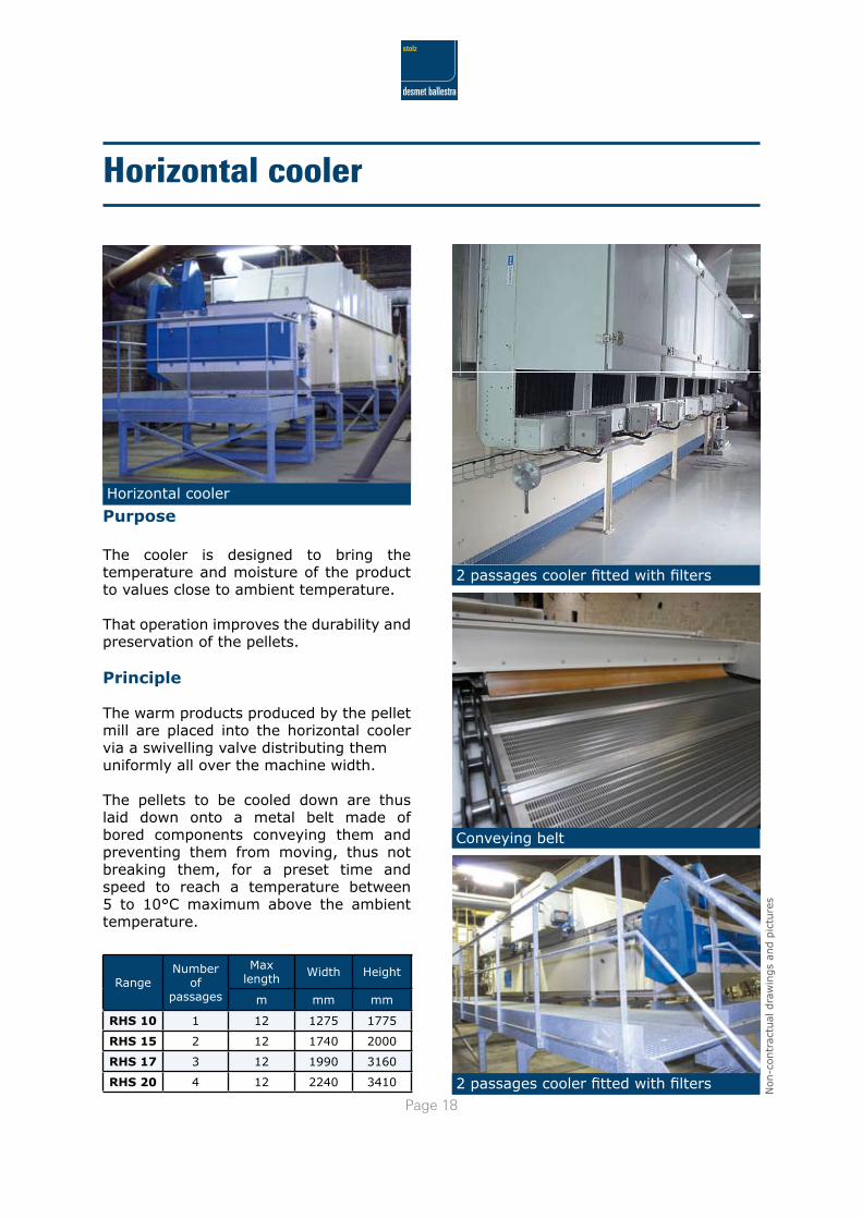
Purpose
The cooler is designed to bring the temperature and moisture of the product to values close to ambient temperature.
That operation improves the durability and preservation of the pellets.
Principle
The warm products produced by the pellet mill are placed into the horizontal cooler via a swivelling valve distributing them uniformly all over the machine width.
The pellets to be cooled down are thus laid down onto a metal belt made of bored components conveying them and preventing them from moving, thus not breaking them, for a preset time and speed to reach a temperature between 5 to 10°C maximum above the ambient temperature.
Horizontal cooler
2 passages cooler fitted with filters
RangeNumber
of passages
Max length Width Height
m mm mm
RHS 10 1 12 1275 1775
RHS 15 2 12 1740 2000
RHS 17 3 12 1990 3160
RHS 20 4 12 2240 3410
Horizontal cooler
2 passages cooler fitted with filters
Conveying belt
Page 1�
Non-c
ontr
actu
al d
raw
ings
and p
ictu
res
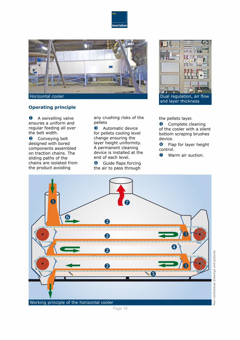
Working principle of the horizontal cooler
u A swivelling valve ensures a uniform and regular feeding all over the belt width.v Conveying belt designed with bored components assembled on traction chains. The sliding paths of the chains are isolated from the product avoiding
any crushing risks of the pelletsw Automatic device for pellets cooling level change ensuring the layer height uniformity. A permanent cleaning device is installed at the end of each level.x Guide flaps forcing the air to pass through
the pellets layer.y Complete cleaning of the cooler with a silent bottom scraping brushes device.z Flap for layer height control.{ Warm air suction.
Operating principle
Dual regulation, air flow and layer thickness
Horizontal cooler
www.stolz.frSTOLZ SEQUIPAG SA, � rue du Colonel DRIANT - ��001 PARIS - FRANCE Tél. +�� (0)1 �� 00 �� �0 - Fax +�� (0)1 �� �� 1� �� - E-mail : [email protected]
Handling equipment & Dedusting
Grinding and milling
Thermal conditionning & Cooling
Pelletizing
Mixing & Coating
Sifting & Cleaning
Services