thermal systems - upm
TRANSCRIPT
Thermal systems 1
THERMAL SYSTEMS
Thermal components, processes and systems ........................................................................................... 1
Thermal systems ................................................................................................................................... 1 Thermal processes ................................................................................................................................. 3 Thermal components ............................................................................................................................. 4
Thermal (system) engineering (projects) .................................................................................................. 4 Thermal engineering tasks .................................................................................................................... 4 Thermal design ...................................................................................................................................... 5 Thermal instrumentation ....................................................................................................................... 7 Thermal data ......................................................................................................................................... 8
Thermal sciences: Thermodynamics, Fluid flow and Heat and mass transfer .......................................... 9 Thermal applications ............................................................................................................................... 11
Thermal conditioning. HVAC&R ....................................................................................................... 11 Ventilation ....................................................................................................................................... 12 Space heating .................................................................................................................................. 13
Heat dissipation ................................................................................................................................... 15 Coolers ............................................................................................................................................ 16
Heat generation ................................................................................................................................... 17 Heat sources (electrical, chemical...) .............................................................................................. 17 Heating systems (heaters, furnaces, boilers...) ................................................................................ 20
Power generation. Heat engines .......................................................................................................... 22 Steam power plants ......................................................................................................................... 23 Reciprocating power plants ............................................................................................................. 23 Gas turbine power plants................................................................................................................. 24
Cold generation. Refrigerators and freezers ....................................................................................... 24 Cold-producing processes ............................................................................................................... 25
Materials thermal processing .............................................................................................................. 26 Biological processing ...................................................................................................................... 26 Chemical processing ....................................................................................................................... 27 Physical processing ......................................................................................................................... 27
Type of problems ................................................................................................................................ 27
THERMAL COMPONENTS, PROCESSES AND SYSTEMS Greek prefix therm means heat (causes and effects, generation and usage), and Latin prefix temper means mixed (originally used for 'temperatura caeli', the sky combination).
THERMAL SYSTEMS In Thermodynamics, a (thermodynamic) system is the part of the physical world that the observer selects to analyse separately from the rest; in between, a frontier is defined through which mass and energy exchanges are precisely identified: an isolated system has no interaction with the rest, a closed system may only exchange heat and work, and an open system may also exchange mass. A thermal system, on the contrary, is a complex assembly of coupled components (some of them thermal), showing a common structured behaviour; e.g. a refrigerator is a combination of pipes, compressor, electric motor, heat exchangers, valves, insulation, casing, doors, lamp, etc., interacting to a
Thermal systems 2
common goal of cold production within. Thus, a refrigerator is a thermal system, whereas the refrigerant fluid or the interior space are thermodynamic systems. Small thermal systems like a refrigerator, usually come fully assembled from the manufacturer (but a simple split-air-conditioning system needs installation), whereas large thermal systems like a refrigerated store, are built on the field. Thermal systems usually demand some services as electrical supply (for power or at least for control), water intake and exit, air intake and exit, fuel supply and flue stack, etc. Thermal system engineering is not usually thought of as a first rank engineering discipline as Mechanical, Civil, Electrical and Chemical Engineering, and it is usually ascribed to the leading one (like Aerospace, Naval, and Automotive Engineering) because the paradigmatic thermal systems has always been the heat engine, but its importance pervades all other branches (e.g. thermal control systems are needed from computer-chip design to communication satellites). A basic grouping of thermal systems may be established according to whether heat exergy, Q, work energy, W, or mass, mi, is transferred through the frontier of the system of interest ('−' if going out, '+ if going in):
• (Q−) Heat dissipation systems: coolers. Heat flows out of the system naturally or accelerated. • (Q+) Heat generation systems: heaters, furnaces, boilers, heat pumps. Heat flows into the system. • (W−) Power generation systems: heat engines, chemical engines, propulsion. Work flows out of
the system. • (W+) Cold generation systems: refrigerators and air conditioners. Work flows into the system to
produce cold (considered above if for heating). • (mi−) Mixture separation and chemical synthesis by thermal processes: dryers, distillers and
reactors. An specific substance must go out of the system. • (mi+) Mixing and dilution: preparation (compounding) or dispersion (waste disposal). An specific
substance must go into of the system. However, other possible grouping may be established according to the type of industry implied, as for thermal systems in (materials) manufacturing (furnaces, casting, extrusion, welding, oxy-cut, refining), or in food processing (cooking, sterilisation, drying, dehydration, the cold chain). In this Chapter 14 we aim at understanding what thermal systems are, and how to analyse them (to be postponed to subsequent chapters), but it is important to broaden for a while our target to see how actual thermal systems are designed, at least to a conceptual stage. Even a sales engineer (and a purchaser) needs to know how thinks work, what are their functionalities, and what performances have been accomplished. In summary, learning is an iterative process like exploring: you first have a rough plan and start walking, dealing with close problems, but from time to time you have to make a stop to integrate what you have learnt and plan further challenges (that you may view as 'conquests' or 'requirements' according to your 'pusher' or 'dragged' mood).
Thermal systems 3
THERMAL PROCESSES Thermal processes are those giving way to thermal effects. Natural thermal effects include, besides the tendency for temperature gradients to die out in an isolated system (strict thermal effects), the tendency for velocity gradients to die out in a suitable reference frame (for an isolated system), and the tendency for concentration gradients (really chemical potential gradients, in absence of external force fields) to die out for an isolated system. Artificial thermal effects aim at forcing the gradients not to die out (at expense of some external exergy consumption). All physico-chemical processes taking place at high or low temperature involve thermal processes, at least to maintain the desired environment and to measure it (high-T thermometry and low-T thermometry are special subjects). A process is a sequence of steps taking place (by natural or artificial forces) between two states of the system, called initial and final states, that may coincide and then the process is said to be cyclic (or steady if no time variation is apparent between the end states). Steady state processes are the most common in thermal systems; cyclic processes are also analysed as a sequence of steady states. Other thermal processes of great interest are iterative process, which are near-cyclic processes where the sequence of steps is repeated always the same, but the working substance do not recover the same initial conditions (e.g. multi-stage refining). The basic thermal processes have already been studied in previous chapters:
• Heat transfer: by pure diffusion, by combined diffusion and advection, or by radiation • Chemical reaction (Chapter 9) • Mixing (Chapter 7, including air drying and humidification in Chapter 8) • Phase change (Chapter 6) • Compression and expansion (Chapter 5),
as well as the general evaluation of thermal energy variations by heat or work exchange (Chapter 1), of entropy variations and entropy sources (Chapter 2), of exergy sources and exergy requirements (Chapter 3), and of data requirements and data sources (Chapter 4). Besides those basic thermal processes, some fluid flow processes must be considered at the same time because most thermal systems are fluid systems. In order of complexity one may quote:
• One-dimensional incompressible flow in pipes connecting thermal subsystems (piping, pumps, restrictions, valves). Pressure losses.
• Empirical thermo-fluiddynamic relations for convective heat transfer. • One-dimensional compressible flow in nozzles. • Real fluid flow processes (boundary layer, wake, turbulence, CFD).
More complex thermal processes, as combustion, materials thermal treatments, and combined processes for power, heat or cold generation, are treated here or in following chapters.
Thermal systems 4
THERMAL COMPONENTS The components of a thermal system (e.g. a power plant, a refrigeration plant, a liquefaction plant) may be other subsystems (e.g. heat exchangers, compressors, valves, mixers, distillers) or basically raw materials (working fluids, solid insulators), and the ancillary elements in thermal installations (e.g. sensors, actuators, controllers, piping and wiring). During operation, the whole thermal system, its components, and particularly the working substances inside, are subjected to natural or artificial thermal processes. Every component, including the working substances and the whole system, has some temperature ranges outside which they do not behave as wanted. Thermal conditioning must then be properly cared about (and there are many components very sensitive to temperature, as electronics components are).
THERMAL (SYSTEM) ENGINEERING (PROJECTS)
THERMAL ENGINEERING TASKS Engineering is the art and science of solving practical problems; thermal engineering addresses the thermal problems, i.e. problems with relevant thermal effects. But problems in real-life are seldom exclusively thermal: even a heat exchanger is a mechanical entity that, besides is thermal goal, posses structural problems (thicknesses, joints, dilatations), chemical problems (corrosions, materials compatibility), handling problems (assembly, inspection, cleaning), logistic problems (availability of materials, machinery, man-power, workshops, warehouses), economic problems (cost of raw materials, manufacturing, marketing, selling), etc. There are many "e" aspects to consider even in genuine energy systems: Energy, Exergy, Economy, Ecology, Ergonomics, Esthetics... (e.g., many air-conditioner buyers take their purchasing decision based on lower noise and not in higher efficiency equipment). Real-life problems must then be solved from all the engineering points-of-view. The approach is to proceed like in sewing, i.e. a combination of parallel interaction and serial iterations, depending on the ratio of man-power to time-allocation, in an interdisciplinary mode called system engineering, to conceptualise, design, built, operate, maintain, or dispose of, the system under consideration. Thermal engineers get from system engineers some general goals and constraints (to which the formers may have contributed a lot, if the problem is focussed on thermal aspects), and start to work to solve the thermal problems, assuming that the other engineering aspects (structural, chemical, electrical, etc.) will be solved "as usual" (thermal engineers need a broad engineering background to know what is "as usual" in the other disciplines, having a common understanding is a prerequisite to collaborative work). The iterative problem-solving process of system engineering may be applied to understand the basic functioning of a thermal system, but where it is really needed is in the design of thermal systems, the most complex of thermal engineering projects.
Thermal systems 5
A project is a case (an instance) in system engineering. The purpose of a thermal project is to deliver to a customer (and maybe to support or operate it, if required) a system comprising one or more elements related to production, consumption or processing of thermal energy. The project activities carried out by the thermal system engineer may be: • Project specification (goal adviser), responsible for creation and maintenance of an envelope of
conditions that satisfy the customers (according to some written requirements and some assumed standards) without too much impact on the rest of the world (other customers and the environment).
• Project management (time and money manager), responsible for achievement of the totality of the project objectives, and specifically for organisation of the project, and its timely and cost-effective execution.
• Project engineering (designer), responsible for definition of the system, verification that the customer's technical requirements are achieved, and compliance with the applicable project constraints. Many models of the system are developed in support of design: mathematical models, mock-ups, engineering models, prototypes and pilot plants.
• Production (builder), responsible for materials procurement, manufacture, assembly and integration of the system, in accordance with the design.
• Marketing (seller), responsible for tailoring the product to satisfy the customers. Except for the case of intricate installations demanding tailored work, this is not properly engineering.
• Operations (operator), responsible for exercising and supporting the system in order to achieve the customer's objectives during the operational phase.
• Product assurance (reviewer), responsible for the implementation of the quality assurance element of the project and also for certain other specialist activities as reliability, availability, maintainability and safety.
THERMAL DESIGN Design is making choices to achieve a goal (i.e. to work out a non-trivial solution). The design task may range from a more or less elaborated sketch to represent an idea (not yet existing or not available at the time and place), with the intention just to be communicated (like in technical descriptive drawing or artistic emotive painting), or may include a prototype realisation of the idea conceived (as in industrial and urban design). Thermal design is just a part of industrial design. To design a physical system (or a component) is to devise (to plan) means to accomplish a stated purpose (user requirements), under explicit and implicit constraints (time, budget, user and social acceptance), from anew or retrofitting. A project is the actual development of the design. Sometimes project and design are used indistinctly to mean the organisation of resources (information, materials, equipment, man-power, financial-power) to accomplish a common objective. The following 'rules of thumb' for system engineering may help to focus the attention also when dealing with thermal system design:
• Everything has a cost (even respiration demands an effort). A trade-off is always implied. Requirements should be weighed against foreseeable cost; rigidity is just a first approximation in

Thermal systems 6
design. Efficiency, the ratio of benefit to cost, must be pursued (the challenge is to accomplish much with little). Most times cost (including environmental costs) can be reduced to economic terms. A project not worth doing, is not worth doing well.
• Everything interacts with everything else. You may (usually you must) decompose the system into subsystems down to basic components, but a shared interface between any two blocks always remains. Best system engineering approach is to decompose the system along the most trivial interfaces.
• Everything goes somewhere. It is a special case of the previous rule when applied to interactions with the surroundings (environment).
• Everything needs to be done, and under the same global budget. The performances of the whole system will normally be lowered to the poorer link in the chain. Everything may look simple to the person who doesn't have to do it. Don't polish work done before finishing the whole. Any postponed task may soar.
• Everything must be verified. One test is worth a thousand expert opinions. A test will be believed by everyone (except perhaps the tester); an analysis may be believed by no-one but the analyst.
• Everything may fail. Minimise risk, plan for contingencies, provide redundancies. Expect the worst and you'll not be disappointed.
A design, even a conceptual design, cannot reduce to a wording description of a solution, not even to a graphical layout of its components and interfaces; a proper design is always based on mathematical quantitative modelling, that establish in more or less detail a set of governing equations (i.e. idealised physical constraints), pinpointing and relating amongst them the most important of the problem variables. And the designer has to verify that the small set of variables selected are really the leading ones, and all the rest have only second order effects. Design is always driven by an extremum goal, that can be:
• Minimisation of effort, cost, risk, input resources, environmental impact, or an appropriate mix. • Maximisation of achievement, profit, benefit, output, appeal, or an appropriate mix.
Experience helps a lot, but sooner or later some experimental trials, with breadboards or prototypes, are needed to elucidate the validity of the model or to find new empirical data to feed the model. Experimental breadboards are set up when difficulties arise in the modelling of the behaviour or interactions of subsystems, with instrumentation for testing, trying to set up a minimum rig, decoupling it from the rest of the system by the most simple and clear interfaces to ensure that partial simulation is representative. The designer has to deal with instrumentation not only for testing during project development, but also for normal operation of the thermal system and for maintenance.
Thermal systems 7
THERMAL INSTRUMENTATION To instrument is to provide the elements and the tools needed for an activity. Instruments may be just measuring devices (with sensors) or actuator devices (usually incorporating sensors). The basic traditional thermal sensor is the mercury-in-glass thermometer, a simple thermal system difficult to design and built (and not so easy to operate, to maintain and to dispose of, if one tries to be precise and respectful, and not coarse and careless). Besides measuring temperature, many other variables are also monitored and controlled in thermal systems: power, pressure, velocities, composition, liquid levels, heat and mass transfer, etc. The type of sensor and instruments available cover a wide range of applications, operating conditions and response time, the most adverse conditions being when working with molten materials at high temperature. Measuring instruments were named ended in -scope (visual and qualitative; e.g. thermoscope), in -metre (visual and quantitative; e.g. thermometre) or in -graph (recorded on paper; e.g. thermograph), although the tendency has been to use -metre exclusively and, instead of a visual reading, to provide an electrical output, to profit from the huge advantages in information management offered by digital electronic computers, summarised in:
• Objectivity: no more need of several human readers to check for different 'points-of-view'. • Redundancy: no more manpower squandering, multiple-time sampling easily affordable. • Simultaneity: no more multiple operators for multiple-location quasi-instantaneous sampling. • Quickness: no more need of massive recording to analyse off-line high-speed phenomena. • Readiness: no more need to postpone the analysis, any elaboration may be implemented within.
The output of a measuring instruments may be just an indicator to inform the user (may be with an alarm to relax continuous monitoring) or a recorder to keep a log, or may be a command to activate an actuator through a controller (more so a command to drive an actuator plus a visual indicator, or a command to drive an actuator plus a ready signal-point to enable a quick connection of an indicator or further information processing if desired). An actuator is an instrument that modifies the state of the system forcing a change in some of its degrees of freedom, requiring a power proportional to the change to be performed. Actuator instruments are named ended in -or or -er (e.g. motor, displacer, heater, mixer). The simplest actuators are on/off switches as in thermostats and pressure switches. Control instruments govern the actuators to enforce a desired behaviour of the system; they verify (by measuring) that the system-output follows the desired trend (by comparison with an objective function), and they send a signal for the actuator to act accordingly. A human operator has always been the paradigm of a controller, and his/her hands the paradigm of actuators, being still today insurmountable controllers in what concerns adaptive behaviour. Control instruments are usually named ended in -or or -er (e.g. regulators, drivers), except for controllers to keep a steady value that are ended in -stat (e.g. thermostat, pressostat)
Thermal systems 8
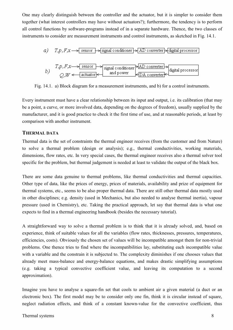
One may clearly distinguish between the controller and the actuator, but it is simpler to consider them together (what interest controllers may have without actuators?); furthermore, the tendency is to perform all control functions by software-programs instead of in a separate hardware. Thence, the two classes of instruments to consider are measurement instruments and control instruments, as sketched in Fig. 14.1.
Fig. 14.1. a) Block diagram for a measurement instruments, and b) for a control instruments.
Every instrument must have a clear relationship between its input and output, i.e. its calibration (that may be a point, a curve, or more involved data, depending on the degrees of freedom), usually supplied by the manufacturer, and it is good practice to check it the first time of use, and at reasonable periods, at least by comparison with another instrument.
THERMAL DATA Thermal data is the set of constraints the thermal engineer receives (from the customer and from Nature) to solve a thermal problem (design or analysis); e.g., thermal conductivities, working materials, dimensions, flow rates, etc. In very special cases, the thermal engineer receives also a thermal solver tool specific for the problem, but thermal judgement is needed at least to validate the output of the black box. There are some data genuine to thermal problems, like thermal conductivities and thermal capacities. Other type of data, like the prices of energy, prices of materials, availability and prize of equipment for thermal systems, etc., seems to be also proper thermal data. There are still other thermal data mostly used in other disciplines; e.g. density (used in Mechanics, but also needed to analyse thermal inertia), vapour pressure (used in Chemistry), etc. Taking the practical approach, let say that thermal data is what one expects to find in a thermal engineering handbook (besides the necessary tutorial). A straightforward way to solve a thermal problem is to think that it is already solved, and, based on experience, think of suitable values for all the variables (flow rates, thicknesses, pressures, temperatures, efficiencies, costs). Obviously the chosen set of values will be incompatible amongst them for non-trivial problems. One thence tries to find where the incompatibilities lay, substituting each incompatible value with a variable and the constrain it is subjected to. The complexity diminishes if one chooses values that already meet mass-balance and energy-balance equations, and makes drastic simplifying assumptions (e.g. taking a typical convective coefficient value, and leaving its computation to a second approximation). Imagine you have to analyse a square-fin set that cools to ambient air a given material (a duct or an electronic box). The first model may be to consider only one fin, think it is circular instead of square, neglect radiation effects, and think of a constant known-value for the convective coefficient, thus
Thermal systems 9
simplifying the real problem to a one-dimensional cylindrical problem that may be already solved in thermal engineering handbooks. Even the further simplification of approximating the cylindrical problem to a planar problem may be worth doing: perhaps the figures change appreciably, but the learning may help a lot (and it can be used to check or validate more complex solutions in some limiting cases). Just considering the thermal data for working fluids, many approximations may be applied; e.g. to consider pure standard substances (pure water instead of tap water, dry air instead of humid air, methane instead of natural gas), to neglect the effect of pressure and temperature in their thermal capacities, to take a typical value of cp=1 kJ/(kg⋅K) for any kind of substance, etc. Traditionally, thermal data are classified in • Thermodynamic data: i.e. state properties for fluids (phase change points, density, thermal capacity,
and equations of state) or state diagrams. Thermodynamic data for solids are usually grouped with their thermophysical data.
• Thermophysical data: focussing on transport data (thermal conductivity, viscosity, emissivity). • Thermochemical data: standard enthalpy, absolute entropy, and maybe combustion data. Although most thermal properties are usually taken as constant, it is just a first approximation, since all thermal properties depend at least on temperature, and to a lesser extent on pressure (without forgetting that there are no such things as a 'pure' substances, e.g. H2O, and all thermal properties depend on the composition). Considering the thermal software data, i.e. the pre-programmed tools to aid thermal analysis and design, one may classify them, from the most straightforward to the most complex, in:
• Thermodynamic function evaluators. They may range from simple calculators (e.g. to evaluate a polynomial expression for the thermal capacity as a function of temperature, or for vapour pressure computations), to simple databases of fundamental physical constants, critical point data, density as a function of substances or variations with temperature and pressure, etc.).
• Thermal analysers. They are just evaluators of well-defined topical problems with explicit formulations (fluids in ducts, compression and expansion, power cycles, heat transfer in typical geometries, etc.).
• Thermal solvers. They are sophisticated packages prepared for iterative analysis as used in the design of thermal systems or complex thermo-fluid-dynamic processes.
• Thermal tutorial soft, might be added to the list, not for initial training, where a human teacher is preferable, but for life-long thermal-science refreshing.
THERMAL SCIENCES: THERMODYNAMICS, FLUID FLOW AND HEAT AND MASS TRANSFER Traditionally, thermal engineering is said to be supported on a three-leg foundation, ordered in the normal chronology of tuition:
1. Engineering Thermodynamics • Functions and variables: energy, entropy, exergy, properties of pure substances. Metrology. • Control volume formulation (open systems).
Thermal systems 10
• Mixtures and humid air. • Chemical reactions and combustion. • Gas and vapour cycles for power and refrigeration machines. • In the general unsteady case, the energy E and exergy Φ balance for a thermodynamic system
are (Chapter 5 and 7):
openingsd
d ee tE W Q m ht= + + ∑
(14.1)
openings
00
d 1d u gen e e
TW Q T S mt TΦ ψ = + − − +
∑
(14.2)
with:
( ) ( )0 0
components
0 0 ,i
it i in T p
i
yh T sM
ψ µ µ≡ − + −∑ (14.3)
ψ being the exergy flow through an opening, yi the mass fractions of chemical species i with chemical potential µi, Mi the molar mass of species i, and m vAρ= .
2. Fluid Mechanics
• Introduction: types of fluids, type of forces, types of flow. Local equilibrium. Metrology. • General equations: mass, momentum and energy balance. Similitude. • Incompressible viscous flow (Couette, Poiseuille, Stokes, Rayleigh, Kármán, lubrication,
porous media). • Incompressible inviscid flow (Euler equations, potential flow, Bernoulli equation, Venturi
flow). Boundary layer, Ekman layer and shear layers. • Instabilities and turbulence. • Free-surface flow. Compressible flow. Multiphase flow. Non-newtonian flows. Machines. • The momentum equation in a general case:
( ) ( ) ( ) 'vDv vv g p gz
Dt t∂ ρ
ρ ρ τ ρ ρ τ∂
= +∇⋅ = ∇ ⋅ + = −∇ + +∇⋅
(14.4)
is usually reduced, in most steady thermal fluid-flow problems, to the simple generalised Bernoulli equation along a streamline s:
2
0
12
s L
mdfs
p gz v w eρ ρ=
=
+ + = − (14.5)
indicating that total pressure pt≡p+ρgz+ρv2/2 is conserved in absence of shaft-work w and mechanical dissipation by friction emdf.
3. Heat and Mass Transfer
• Heat conduction: conductivity and heat-flux measurement. • Heat convection: natural/forced, internal/external, thermal boundary layer. • Heat exchangers: shell-&-tube, compact, contact. • Heat radiation: electromagnetic spectrum, black-body, optical properties, view factors. • Heat transfer with phase change: evaporation, condensation.
Thermal systems 11
• Mass transfer: conduction, convection and phase change. Wet towers. • The heat equation in a general case:
( ) 2
2' :( )
( )i if p i
p p
Dpv Th c T T yT Dta T Tvt c c
φ τ α∂∂ ρ
⊕ ⊕ + ∇ ++ − ∇= ∇ − + −∇ ⋅
∑
(14.6)
is usually reduced in many thermal applications to the simple lump model of heat transfer rate from a system at temperature T to the ambient at temperature T0:
03
for conduction
( ), with for convectiond
4 for radiation (linearised)
kLdTmc Q KA T T K h
tTεσ
=
= = − = ==
(14.7)
Thermal Engineering then applies these foundations to solve thermal problems of heat dissipation (cooling and coolers), heat generation, energy dissipation (mechanical, electrical or chemical), combustion, power generation (heat engines), cold generation (refrigerators and coolers), materials processing: separation, synthesis and thermal treatments, waste removal, etc. A quick review of these possible applications follows.
THERMAL APPLICATIONS
THERMAL CONDITIONING. HVAC&R Thermal conditioning (or thermal control) aims to achieving a desired temperature in a material, component, or system. HVAC (pronounced either "H-V-A-C" or "aitch-vak") is an acronym that stands for "Heating, Ventilating, and Air Conditioning", all related technologies used for indoor environmental comfort (basically air conditioning, AC, but also sanitary water heating, WH). Refrigeration is sometimes added to the field, extending the abbreviation to HVAC&R. Ambient pressure is assumed to be a constant in most HVAC application (residential, office, and terrestrial vehicles), but it has to be regulated in pressurised environments as submarines, aircraft and spacecraft. Air quality is assumed to be guarantied by ensuring some standard ventilation (fresh-air renovation with say 5 litres of outside air per second per person), so that the key variable to control in HVAC&R is temperature (heating, or cooling), and, to second order, relative humidity (humidification, or dehumidification). Besides air quality, pressure, temperature, and humidity, environmental control may demand proper illumination, proper acoustics, and other ergonomic and aesthetic conditioning. HVAC equipment may range from small stand-alone units like stoves and through-the-window air conditioners, with minimum or no installation demands, to central heating and air-conditioning installations, with their own machine room and a complex piping network.
Thermal systems 12
Ventilation
Ventilation is the renewal of ambient air, and may have several objectives: • Sanitary renovation of breathable air in habitable spaces; i.e., removing foul air (contaminated
with CO2, odours, microorganisms, and other particles) and supplying fresh air, at a rate of at least 2 litres of fresh-air per second per person (10 L/s for smokers; ASHRAE-1989 standard was 7 L/s). Airliner standard cabin-air supply is 9.4 L/s per person (20 cfm), half fresh and half recycled (filtered).
• Convective cooling of living and powered systems; i.e., removing heat from any operating item (persons, animals, plants, electrical devices, chemical processes, and so on). The rate of ventilation required depends on dissipated power and maximum allowed temperature. Most electrical appliances come with ventilation grids, which must be left unobstructed for operation.
• Convective entrainment of matter in air-consuming, vapour-generating and dust-generating processes, to keep operating the process; e.g. to keep a fire burning, to get rid of odours, etc.
When ventilation must take in fresh air with a large temperature difference to that of the conditioned space, it may be important to recover heat (to pre-heat fresh air in winter) and cold (to pre-cool fresh air in summer). Ventilation can be achieved by different means:
• Natural ventilation caused by a density gradient in a gravity field (the chimney stack effect). Density gradients can be due to a thermal gradient or a concentration gradient. The driving force is the pressure unbalance between the light and the heavy air columns: ∆p=∆ρgL. Notice the importance of the high of the air columns, L, what explains that the higher the chimney the stronger the draught. That is why windows for ventilation should be higher than wider (already in the ordinances of Charles I of England). This kind of ventilation is the best for health, the others causing too-much draught (in general, if an air current attracts our attention, then it is too much for comfort and may be a hazard to health).
• Natural ventilation caused by natural winds, either directly impinging on the object, or creating secondary air-currents by aerodynamic effects. This is the typical ventilation means used in houses, residential buildings and small commercial and industrial buildings, where the users must open windows and/or doors from time to time (usually when cleaning, or when setting beds). All doors inside buildings are allowed for some air infiltration.
• Forced ventilation by fans, when natural ventilation is not good enough, as in large commercial, office, and industrial buildings (and in confined environments like submarines, aircraft and spacecraft).
Notice that a person processes a minimum of 0.1∙10-3 kg/s of air in respiration, consuming a minimum of 5∙10-6 kg/s de O2 and generating a minimum of 7∙10-6 kg/s de CO2 and a minimum of 3∙10-6 kg/s de H2O. Skin transpiration contributes in an even greater amount of H2O. An adult at rest inhales 0.5 L twelve times per minute; air composition at inhalation is 77% N2 + 21% O2 + 1% H2O + 1% Ar + 0.04% CO2 (asphyxia is produced if xO2>18%, by anoxia), whereas air composition at exhalation is roughly 77% N2 + 16% O2 + 3% H2O + 1% Ar + 3% CO2 (xCO2=40 000 ppm in volume; normal respiration can be sustained
Thermal systems 13
in atmospheres with up to xCO2=1000 ppm; fresh-air is assumed to have xCO2=380 ppm, but in large-city centres it might reach double concentration). The intake varies from 0.5 L to 2 L on deep gasps, and the rate varies from 12 breath/min to 120 breath/min on panting. When fresh air is not available (as in space and underwater vehicles), there is a need of more complex environmental control for life support systems (ECLSS).
Space heating
Space heating is surely the oldest of the thermal technologies (notice that the average temperature in the ecosphere is 15 ºC whereas human comfort is at 20..22 ºC, and ice-age temperatures were some 9 ºC below today’s average level). It is far more reasonable to heat enclosed or sheltered spaces, than doing it in the open air (as in camp fires), but heating by burning a fuel poses the old problems of smoke and safety. Several space-heating solutions have been developed through the ages, namely:
• Fireplace in a ventilated room (initially a cave-shelter), with a zenithal hole to get rid of combustion emissions. Notice the trade-off between heating and ventilation, and the difficulty to ventilate single-opening cave wells and domes (lack of natural draught).
• Protected fireplace and chimney, i.e. a bell-shape mouth built on top of the fire, with a wall behind to refract the heat and a long vertical duct to conduct the foul gases out.
• Stove and chimney, i.e. the fire completely enclosed from the space to heat, except for small openings for air intake. Iron stoves appeared in China I c. a.D. and in Europe in the XV c., with its basic design consolidated by B. Frankling in 1742. The fuel was initially wood, then charcoal, coal from the XVII c., town-gas or kerosene from mid XIX c., and waste-wood pellets recently (electrical stoves started in 1914).
• Air-tight fireplace, i.e. with both the flue and the intake ducted with the external atmosphere. In this case, the room can be better heat-insulated (only air for breathing has to be renewed).
• Combustion taking place outside of the space to heat, the energy being brought by a carrier fluid that can be the hot flue gases (without mixing with room air, as the ancient ‘glorias’, already used in Crete XX c. b.C.), hot air that can directly mix with room air (already used in Crete XX c. b.C.), or better hot water (Romans had space heating and sanitary hot water II c. b.C., with the climax II c. a.D. with Caracalla’s thermae). Space heating based on hot-water ‘radiators’ at the walls (at the coldest side, e.g. below windows) is most used because it is a clean, efficient, and quiet solution, requiring small pipes (but may leak!). Space heating based on ducted hot air demands larger ductwork, are noisier, and may compromise air quality (air ducts are exposed to contaminants difficult to clean), but the air-duct systems can be easily used for both heating and cooling, whereas the radiators in hot-water systems cannot cool enough (water cannot be pumped much below 5 ºC if freezing is to be avoided, and the temperature difference is three or four times smaller than in the heating case). The best heating system might be a low-temperature hot-water-net under the floor (‘radiant floor’, at some 30 ºC to 35 ºC).
• Non-burning heating systems, either electrical heating; which is the simplest and cleanest solution (but less dynamic and much more expensive), or using a heat pump, which is more
Thermal systems 14
expensive in acquisition, running, and maintenance costs, but it can provide both heating and cooling.
Space heating is the major energy consumer at home in developed countries (most of them in the temperate zone between 30ºN and 60ºN). In the residential sector in EU, some 55% of the final energy is devoted to space heating, and 25% for domestic hot water (both fuel-based), the remaining 20% covering all electrical appliances and cooking. Several types of thermal loads can be considered in calculations of required space heating (also applicable to air-conditioning) in buildings (a whole buildings or part of it):
• Opaque envelop loads, due to heat transfer through the impermeable walls, including ceiling and floor, but excluding solar-radiation inputs through the glassing.
• Glassing loads, i.e. due to heat transfer through the part of the envelop permeable to solar radiation: glassing and openings.
• Infiltration loads, i.e. due to heat convection through air-permeable openings: door slits, window leakages, flue, ventilation grills, etc. Nowadays, in properly insulated dwellings, this is the main contributor to heat losses in winter and heat gains in summer.
• Appliances and metabolic loads, i.e. due to heat dissipation processes in the interior due to persons, animals (roughly 1 W/kg), plants (roughly 0.1 W/kg), electrical appliances (e.g. cooking range, lighting, computers).
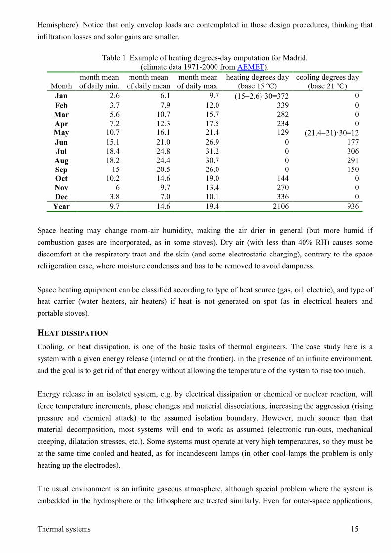
Heat gains through the walls are proportional to the temperature jump and envelop area, Q KA T= ∆ , with an overall heat-transfer coefficient K (sometimes written U; other times, the thermal resistance R=1/K is used instead of thermal conductance) depending on construction details. Envelop area is nearly fixed by the particular application, and the temperature jump also fixed by local climate, thence the trade-off is between low K-values that increase acquisition cost (e.g. double glazing, air gaps, thermal breaks) and decrease running cost, or high K-values that that decrease acquisition cost and increase running cost; with high-energy costs, the former is favoured. For building envelopes in EU, K is nowadays in the range 0.25..0.45 W/(m2∙K), having shown a great improvement in the last decades due to increasing regulations on the building sector for proper thermal insulation (e.g. it was around K=0.55 W/(m2∙K), in 1995; and 0.8 W/(m2∙K) in 1985). The total energy demand for space heating in a period (usually a month, but may be the whole season or a year), with constant values for K and A, is evaluated by an approximation of Q=KA∫∆Tdt, which can be done by several methods. A simple ‘degree-days’ method does it by summing up (over the period) the difference between a standard reference temperature, Tref (usually 15 ºC, but 15.5 ºC and 18 ºC are used in some countries) and the monthly-mean of daily-minimum outside dry-bulb temperature, Tmin,mean, only if this difference is positive (see example in Table 1). Other curve fittings can be used to better approximate outdoor temperature versus time (e.g. a sine fitting to the maximum and minimum daily temperatures). A similar degrees-day method can be applied to calculate cooling loads in summer, changing the reference temperature; 21 ºC is used in Table 1). The maximum heating power needed is calculated by a suitable choice of ∆T in Q KA T= ∆ , e.g. ∆T=Tref−Tmin,mean,win, with Tmin,mean,win being the daily-minimum coldest-month average (January minimum temperature in the Northern
Thermal systems 15
Hemisphere). Notice that only envelop loads are contemplated in those design procedures, thinking that infiltration losses and solar gains are smaller.
Table 1. Example of heating degrees-day omputation for Madrid. (climate data 1971-2000 from AEMET).
Month
month mean of daily min.
month mean of daily mean
month mean of daily max.
heating degrees day (base 15 ºC)
cooling degrees day (base 21 ºC)
Jan 2.6 6.1 9.7 (15−2.6)·30=372 0 Feb 3.7 7.9 12.0 339 0 Mar 5.6 10.7 15.7 282 0 Apr 7.2 12.3 17.5 234 0 May 10.7 16.1 21.4 129 (21.4−21)·30=12 Jun 15.1 21.0 26.9 0 177 Jul 18.4 24.8 31.2 0 306 Aug 18.2 24.4 30.7 0 291 Sep 15 20.5 26.0 0 150 Oct 10.2 14.6 19.0 144 0 Nov 6 9.7 13.4 270 0 Dec 3.8 7.0 10.1 336 0 Year 9.7 14.6 19.4 2106 936
Space heating may change room-air humidity, making the air drier in general (but more humid if combustion gases are incorporated, as in some stoves). Dry air (with less than 40% RH) causes some discomfort at the respiratory tract and the skin (and some electrostatic charging), contrary to the space refrigeration case, where moisture condenses and has to be removed to avoid dampness. Space heating equipment can be classified according to type of heat source (gas, oil, electric), and type of heat carrier (water heaters, air heaters) if heat is not generated on spot (as in electrical heaters and portable stoves).
HEAT DISSIPATION Cooling, or heat dissipation, is one of the basic tasks of thermal engineers. The case study here is a system with a given energy release (internal or at the frontier), in the presence of an infinite environment, and the goal is to get rid of that energy without allowing the temperature of the system to rise too much. Energy release in an isolated system, e.g. by electrical dissipation or chemical or nuclear reaction, will force temperature increments, phase changes and material dissociations, increasing the aggression (rising pressure and chemical attack) to the assumed isolation boundary. However, much sooner than that material decomposition, most systems will end to work as assumed (electronic run-outs, mechanical creeping, dilatation stresses, etc.). Some systems must operate at very high temperatures, so they must be at the same time cooled and heated, as for incandescent lamps (in other cool-lamps the problem is only heating up the electrodes). The usual environment is an infinite gaseous atmosphere, although special problem where the system is embedded in the hydrosphere or the lithosphere are treated similarly. Even for outer-space applications,
Thermal systems 16
the philosophy is the same except that only heat dissipation by radiation to the background universe at 3 K is ultimately available. The basic mechanism for heat dissipation from a system to the atmosphere is by natural convection, i.e. by heat transfer from the surface (wet area A) of a hot system (at T=T0+∆T) to a dilatable atmosphere (at T=T0, with thermal expansion α) in the presence of the gravity force (buoyancy is proportional to these three effects: ∆T, α and g). The overall heat transfer is Q KA T= ∆ , where K is the global thermal transmittance, that depends on the material properties of system and atmosphere, flow properties, and temperatures. Cooling by natural convection is a key role of ventilation, usually combined to heating and refrigeration under the term HVAC-engineering. When the basic natural-convection cooling must be enhanced, the approach may be:
• To decrease unwanted energy inputs: shade from sun rays, avoid nearby hot objects. • To increase the thermal transmittance of the sink (the atmosphere):
• by avoiding restrictions to air motion: leave ample room between the system and nearby walls, floor and ceilings.
• by choosing a location where some natural air draught already exists. • by forcing an artificial air flow (this is an active system that requires a continuous expense of
energy). • by forcing an artificial intermediate fluid flow to be later cooled (an active system). • by enhancing the radiative coupling with the surroundings, increasing the emissivity for
infrared radiation and decreasing the absorptivity for visible radiation. • To increase the system area wetted by the atmosphere (A), either by adding fins to the system, or
by placing the system on a larger heat conducting plate that acts as an intermediate sink. • To increase the thermal transmittance of the source (the system), i.e. to efficiently move the
dissipated energy from the inside to the surface: • by increasing the thermal conductivity of the system, enhancing joint conductance or adding
internal conductors. • by increasing the convection inside a system (e.g. with internal fans that, although contributing
to the heat source, redistribute more evenly thermal energy). • by enhancing the radiative coupling in the insides (e.g. painting internal surfaces black). • by a special thermal bridge, as a heat-pipe, inside which a working fluid boils in one side and
condenses on the other end. • To procure endothermic physicochemical reactions, as the evaporative cooling in animal sweating
and industrial cooling towers.
Coolers
A cooler is an artificial device to enhance natural cooling, preventing excessive temperatures, and may be active (i.e. powered; e.g. a fan, a pumped heat exchanger) or passive (un-powered, as the fins added to

Thermal systems 17
extend a surface, cold plates and radiators, a heat-pipe, a thermo-siphon heat exchanger). Natural cooling is termed ventilation. Sometimes the name cooler is improperly used as synonymous of refrigerator (or even freezer). A cooler just accelerates the natural process of thermal relaxation of a hot system, whereas a refrigerator has to overcome the natural process of thermal relaxation of a cold system, necessarily expending some external exergy. A typical cooling system is the ‘refrigeration’ system for the car engine, a pressurised water loop with a pump forcing water through the outside walls of the combustion cylinders and then through a forced-air ‘radiator’, to provide thermal conditioning to working materials.
HEAT GENERATION The case study here is a system that needs to be heated, i.e. that requires some energy input, most of the times with the intention to rise its temperature, but other times with the aim to force a phase change or just to maintain some temperature against heat losses (as in space heating). Heat generation is indeed the most simple process to realise: all conceivably natural processes (mechanical, hydrodynamic, electrical, optical, chemical, nuclear, etc.) degrade energy that will eventually flow out as heat to the ambient. But one surely realises also that sometimes it is not enough to rub one's hands to get warm, and nobody relies on stirring the coffee to get it hot. There are many applications that require heat generation, as:
• Space heating, for human comfort (leisure) or for convenience (business) of people, animals, plants or materials.
• Sanitary water for human hygiene (faucet, shower, bath) and other domestic uses (dish-washer, cloth-washer).
• Materials processing: food cooking, sterilising, drying, melting, welding, burning, cutting, heat treatment (annealing, curing), plasma generation.
• Exergy input to thermal machines, i.e. to drive heat engines or absorption refrigerators and heat pumps.
A traditional classification of heat generation devices is as follows: generic heaters, furnaces, and boilers, the two last-named being just special systems associated to heaters: a furnace is a well-isolated place with a heater, and a boiler is a pressurised vessel for vapour generation with a heater.
Heat sources (electrical, chemical...)
According to the energy source, one possible classification of heating elements may be: • Mechanical heating. Based on dissipation of mechanical energy by friction, that may range from
the rubbing of one's hands, to welding rods by spinning under pressure, passing by the intense stirring of a fluid.

Thermal systems 18
• Ultrasonic heating. Any propagating wave in a medium suffers some absorption that gives way to an increase in internal energy (heating), proportional to the intensity of the field, that decreases along the path (similar for ultrasonic and microwave propagation). The typical ultrasonic frequency for heating is 1 MHz. Selective elastic-energy dissipation, as by hysteresis in cracks, is used for non-intrusive diagnostics by thermography.
• Electrical heating. May be based on: • Joule dissipation in an electrical conductor, which may be an electrical resistance or an
electrical conducting load. Works with direct or alternate current. The energy balance for a Joule-dissipating solid is 2 2/ /mc dT dt W I R W V R= − = − . At steady state, for a given voltage V, the more resistance the less heat release; but resistivity cannot be too small because then the material cannot withstand the temperature rise (a resistor is intermediate between an open circuit and a short circuit). In practice, resistors are made of bad solid conductors like carbon, Cr-Ni, Fe-Cr-Al or Si-Al-Co alloys, or ceramic-metal compounds (i.e. ‘cermets’, e.g. silicon carbide SiC, or better molybdenum di-sillicide, MoSi2, for >1500 K). Besides resistors (special components), resistance heating is also used for welding (not only in the hot copper-tip tin soldier, but also on point welding and butt welding).
• Electromagnetic induction in an electrical conductor acting as a short-circuit secondary inside a primary coil (requires alternate current, to produce a variable magnetic field, as in transformers). Energy is dissipated by Joule effect in the currents opposing the induction (as in a transformer kernel), known as Foucault or parasite currents, and, to a lesser extent (from 5% to 30%) by hysteresis-cycle effects due to the non-linearity between magnetic flux and induced intensity in ferromagnetics. The depth of penetration of this current depends on the frequency of the inductive current: the higher is the frequency, the more superficial is the heating. Notice there is no contact between the power coil and the load.
• Arc heating. The arc heating is a special case of resistance heating where the resistor is a plasma (at some 10 000 K), generated between two electrodes across a dielectric (the surrounding air or the load itself) during the course of heating. When the arc is fed with hot combustion products, it is then called a plasma beam or plasma arc.
• Heat pump. Although not necessarily electrical (any exergy source may work), most heat pumps are a kind of vapour compression refrigerator with the compressor driven by an electrical motor (see below on Refrigerators or in Chap. 18 for details).
• Radiation heating. Different electromagnetic radiations (emitted by any means) that cause direct heating of the load (the air being nearly transparent). In order of increasing unitary radiant energy (E=hν), non-ionizing radiation heating may be: • Microwave radiation (MW), only applicable to polar molecules, like water (and derivatives
like aqueous solutions, food…), because they only excite rotational levels in polar molecules. Typical frequencies for heating are in the range 0.9..2.5 GHz, produced with a magnetron. MW-heating is very energy-efficient because it is absorbed directly by the load (on transparent containers) and not only at the surface but along a rather thick penetration depth (around 1 cm). The only damage on living matter microwaves can cause is excess heating, like in a conventional oven.
Thermal systems 19
• Infrared radiation (IR), as in low-temperature incandescent lamps and CO2 lasers. IR-heating may help to dry and cure transparent coatings from inside out (better adhesion).
• Visible radiation, as in some green and red lasers used in materials cutting, and halogen and incandescent lamps. Up to 4000 K have been obtained with large solar concentrators (solar ovens).
• Ultraviolet radiation (UV), used as curing agent in polymers. UV-radiation can damage living matter by creating long-lived excited states and radicals in important biomoléculas like DNA and melanin. Beyond UV frequencies (X-ray and γ-ray), electromagnetic radiation cause damage by ionisation, as well as other energetic particle radiations (electron beams, proton beams, and neutron beams, to be considered under nuclear heating, below).
• Nuclear heating: • Nuclear radioactive decay of natural or artificial unstable heavy atoms by sequential emission
of small particles (all of the actinide elements are radioactive, but with very different half-lives: 4.5⋅109 years for U-238 and 0.7⋅109 years for U-235). Only used as heat sources in radioisotope power plants in space probes (e.g. with Pu-238, producing 600 W/kg with a half-life of 88 years).
• Nuclear fission, i.e. directly splitting in two nearly-equal atoms by capture of a neutron, instead of a sequential decay, of heavy atoms (the only fissionable natural atom is U-235, found in 0.72% in most uranium ores, all the others being artificial, as Pu-239 from natural U-238, and U-233 from natural Th-232). Used in nuclear power stations, as prime mover and, in some cases as waste-heat district-heating systems.
• Nuclear fusion, reaction of nuclear aggregation of light nucleus (deuterium, tritium) at extremely high temperatures as in the Sun (more than 106 K; the nuclei had to approach to 10-
15 m to react). Plenty of source material in ordinary water (150 ppm of deuterium), but not yet under human control.
• Chemical heating: • Reaction heat: the combustion reaction is by far the most widely used method of heat
generation, from catalytic combustors below 1000 K, to the oxy-acetylene torch at 3500 K. According to the contact between the heating load and the combustion substances, the heating may be without contact, with direct contact with the exhaust gases, or with direct contact with the fuel. When the hot combustion products are further energised in an electric arc (up to two or three times the heating value of the fuel), it is called a plasma beam or plasma arc.
• Mixing heat. • Phase change heat.
Industrial heating when combustible vapours exist (e.g. because of organic solvents used in painting, adhesives, cleaning, plastics), may be difficult for the risk of electrical sparks or high temperatures (higher than the autoignition temperature of materials involved). Sometimes, the best solution is radiative heating with catalytic burners with maximum temperature (say 800 K) below the autoignition value (an additional advantage when drying or curing is implied is that radiant heat may penetrate a layer and start drying or curing from the inside out, with better adherence to substrate.
Thermal systems 20
Although the energy from commercial fuels is 2 or 3 times cheaper than electricity, most heating devices for cooking ranges, washing machines, dish washers, vapour cleaners, and so on, are electric because of the following advantages:
• Cleaner. No contamination of the system to be heated (but larger contamination at the power station site).
• Cheaper to install, to maintain and to repair (but more expensive to run). • Better control (quick on/off, easy modulation, little inertia, no empty-fuel-reservoir, safer). • Wide range of possibilities (resistance, induction, IR-radiation, MW-radiation, laser).
Heating systems (heaters, furnaces, boilers...)
A heating system may comprise the heat source, the heat appliance (the heater itself), and the heat receiver (the heat load): a stove, a boiler, a furnace... The word cooker may refer to the cooking pot (e.g. pressure cooker) or to the heating appliance (e.g. electrical cooker). Stoves for space heating, and ranges for cooking, are here included. A heater is a device that release energy to an external load (room air, water, or any other material). Most heaters are electrical (i.e. electrically powered) because of convenience of use (cleaner, easier to install, start and control), but the most powerful heaters are based on combustion of natural gas (or a crude-oil distillate); fuel-fired heaters are cheaper to run and quicker to start. At home, for instance, most heaters are electrical (the iron, the toaster, the microwave oven, and maybe the cooking range, the dishwasher heater, the washing-machine and dryer heaters, but very rarely the sanitary water heater or the space heating system, that are usually based on combustion. Concentrated heaters can be more efficient if the surrounding fluid is forced to move, as in fan-coils, where a hot-water stream (or a cold refrigerant for cooling) is blown with room air. A furnace (or oven, or kiln) is a vaulted enclosure where energy is released to an internal load (e.g. to a food or material) to be processed in a batch or continuous sequence, for some specific application: baking, curing, drying, bonding, hardening (tempering), softening (annealing, stress-relieving), melting, incineration. Furnaces may have a box shape, a tubular shape for linear gradients, a crucible shape for melting, and so on, but they are usually classified according to the energy source they used: electric or fuel-fired, the former sub-classified as resistance, induction, microwave and arc furnaces (see below). Sometimes the heating element (the electrical element or the burner) is considered separately from the furnace. All furnaces have insulating lining at the walls, that for high temperature work must be of refractory materials, with a door or moth for feeding the load, and a vent to get rid of materials out-gassing (and combustion products if fuel-fired). One of the main burdens in batch operation is the time and energy waste during heat-up and cool-down of the furnace walls.
Thermal systems 21
Furnace operating temperature goes from the 250 ºC of food baking applications, to 500 ºC of soil drying, glass work and metals annealing applications, to 1000 ºC for heat-treatment of metals and CaCO3 calcination, to 1500 ºC for smelting and common glass making, up to 2000 ºC for the most demanding work, as vitrification and refractory smelting. Most common furnaces use vacuum-formed Al2O3 fibre-boards on the hot face as refractory lining. Furnaces to bake pottery were developed at least 6000 years b.C., and metallurgical applications can be found 3000 b.C. Within a fireplace, it is very difficult to reach 600 ºC; baking pottery requires heating the clay at least to 900 ºC, or up to 1200 ºC in the case of the white clay for porcelain; glass making requires the complete melting of the clay at a minimum of 1300 ºC, in spite of the temperature-reduction due to the natron flux (hydrated sodium carbonate) usually added. A kiln is a large oven for burning, drying, or processing ceramic materials. Furnaces usually operate at room pressure; autoclaves, however, heat the load with steam at high-pressure, and are much used in sterilisation. A home pressure cooker is a strong pot that can be hermetically sealed, in which food is quickly cooked under pressure at a temperature above the normal boiling point of water. A boiler is a closed vessel to produce steam or any other vapour (usually at high temperature, what implies a very high pressure), by heating (vapours can be generated also by vacuum). Boilers may have the heater inside (e.g. a submerged electrical resistance), or outside through a fluid heat source (e.g. burning gasses, and then they are really fluid-to-water heat exchangers). The word boiler is also used (improperly) to design the water heater used for domestic space heating (the water does not boil off!). The first boiler-like description dates back from Hero of Alexandria around 150 a.D., but it was in 1679 with Denis Papin's first pressure-vessel and first safety-valve that real practical developments started, followed by Trevithick's-1804 fire-tube boiler, and Wilcox's-1856 water-tube boiler, the latter inherently safer because the high pressure is confined to the small tubes, not in the large shell (Babcock joined Wilcox in 1866, starting the large boiler manufacturing firm; rudimentary water-tube boilers were built before Wilcox's (a patent by Blakey dates 1766) but were inefficient and not much used). Boiler water must be treated with chemicals and biocides for proper operation. Boiler types may be grouped by pressure-level, type of construction (nowadays most are water-tubes), type of fuel (gas, oil, coal, nuclear, electrical) and size (capacity; typical boilers yield 2..8 kg/s of vapour at some 2 MPa).
• According to its pressure: • High pressure (Dp>0.1 MPa) steam, that may be Power-HP (if D>0.4 m) or Miniauture-HP
(if D<0.4 m). • Low pressure (Dp<0.1 MPa) steam or high pressure water-heater (Dp>1 MPa).
• According to the water and fire arrangement (water must always be pressurised to get high-T vapour): • Pressure-vessel (Watt-1785) with water externally heated by the flue gases.
Thermal systems 22
• Pyro-tubular (or Scotch boiler). The flue gases penetrate or are created inside the pressure vessel with water. Evans-1800. pv<2 MPa. The tubes work at compression, and the shell at expansion.
• Aqua-tubular (or drum boiler, or Parsons-type). A non-pressurised vessel lodges the flame and flue gases, inside which pressurised pipes carry the water and/or its vapour. The tubes work at expansion, and the shell does not work
Gas-pressurised, vapour pressurised and hot-water pressurised vessels, may explode because they have a lot of exergy. There were many boiler explosions in the XIX c. and early XX c. until the first ASME Code for Pressure Vessels of 1915. There are several devices to control boiler operation:
• Relief valve (pressure regulator): opens proportionally to excess pressure. • Safety valve (usually several units, stepped); it opens fully when activated (pops), and may be:
• Reversible (closes after low-pressure recovery; e.g. spring-loaded type). May be tested. • Irreversible (abnormal operation; permanent damage; must be replaced). Statistical test.
POWER GENERATION. HEAT ENGINES The case study here is a system that produces mechanical or electrical work at a certain rate, i.e. power (we use 'power' as synonymous of mechanical or electrical power, and add an appropriate adjective if not, as for thermal power, radiant power, and so on). The power produced may be used to drive a machine or a craft, or to produce heat or cold, or to separate or synthetise substances. At a steady state, power generation requires an exergy input at least equal to the power output, what may be provided by a work source, a heat source or a mass source, thus, any power-generation device is really a power-conversion device. From the beginning, people used their muscles to produce power (to do some work at some rate), but the averaged output is a meagre 10 W (consuming some 100 W of metabolic chemical power), going to a sustainable 100 W of power output for just a few hours a day of exhausting work. The subsequent mastery of fire in the Palaeolithic, at least 500 000 years ago, greatly increased that figure but was only used to produce heat and light, and not work. In the Neolithic, some 10 000 years ago, people learnt to produce mechanical power from animal power and from the power of water streams and wind, to an average of 1000 W per unit. It is only since the Industrial Revolution, some 200 years ago, that we master 'the motive power of fire' (to use the title of Carnot's unique publication), with the largest portable units producing more than 100 MW of power (1000 MW for nuclear power stations units). Power generation may be accomplished by many different systems (leaving aside animal power):
• Electrical systems: e.g. photovoltaic panels (radiation driven), batteries and fuel cells (chemically driven).
• Mechanical systems, e.g. hydraulic (water-driven) and aeolic (wind-driven) power plants. • Thermal systems: e.g. combustion, nuclear, geothermal and solar-thermal plants.
Nowadays, most of the generated power worldwide originates on thermal power plants: more that 80% of the 50 EJ produced in the world in 2000 for motive and electrical work, was by heat engines; the rest by
Thermal systems 23
hydroelectric plants. The heat input comes basically from combustion of fossil fuels (80%; the other 20% by nuclear fission). Two of the great problems to humankind come as a consequence of this present situation in power generation: 1) fossil fuels and fissionable materials are basically non-renewable, with an estimated exhaust time of some 100 years; 2) material residues of present-day combustion and fission reactions are detrimental to our environment (global warming, acid rain, smog, ionising radiations). Besides these problems of energy sources and contamination, other major humankind problems are the access to potable water, food, shelter, sanitation and education. Focussing on the technicalities of power generation, the thermal power system consists of a working substance evolving inside a so called 'heat engine', i.e. the machine that provides mechanical support, containment and interfacing to the working fluid, with an exergy input (usually a mass flow rate of fuel) and a work output (usually a rotating shaft that drives a propeller or an alternator). The working fluid may be an intermediate recycled fluid, like water in steam engines and nuclear power stations), or directly the reactant products of the fuel with air, in a non-recycled-fluid internal combustion engine (reciprocating or rotatory). The type of fuel has changed with time: wood, coal, oil and natural gas (biofuels in the future?). As for nuclear 'fuels', the only natural source is U-235, present in a 0.7% in natural uranium (usually as UO2 mineral) and mainly used enriched up to 3% in U-235. In all of these thermal power plants the energy efficiency, work output divided by heat input, lies today between 20% and 50%, with a typical 35% being the usual value. There are three main types of heat engines; in chronological order of development: steam power plants, reciprocating power plans, and gas-turbine power plants.
Steam power plants
In steam power plants, the working substance, water, gets boiled by the heat source, and the vapour moves a steam turbine. The heat source may be the combustion of any kind of fuel, a nuclear reactor, solar energy, etc. They are the largest of the thermal power plants: up to 400 MW with coal boilers, and up to 1300 MW with nuclear boilers, and are only used to generate electricity or to propel very large ships. The main thermal subsystems are: boiler, turbine, condenser and pumps, and the working fluid follows a so called Rankine cycle (Chap. 17).
Reciprocating power plants
In reciprocating power plants, the working substance is a gaseous mixture able to sustain the internal combustion of a fuel and air; in the past, there were reciprocating power plants using steam generated in an external combustion boiler. They are really chemical engines, but they can be assimilated to heat engines where an inert gas would get the heat released in the chemical process. There are two types of reciprocating power plants: the larger (reaching up to 100 MW) are of so called 'Diesel' type, where ambient air is first compressed and then the fuel added, inflammating because of the height temperatures achieved in the air compression; the other
Thermal systems 24
type is called 'Otto' type, where fuel and air are premixed before being spark-plug ignited, requiring more refined fuels (gasoline, liquefied petroleum gases, natural gas). The thermal subsystems in a reciprocating power plant are not as easily identifiable as for a steam or a gas turbine plant; one may consider the charge renewal and disposal, the combustion process, and the heat transfer through the walls (including the refrigeration), as main thermal aspects. Reciprocating power plants are used for practically the whole fleet of cars, lorries, many trains and most ships, as well as for small and medium stand-alone electric generators.
Gas turbine power plants
In gas turbine power plants, the working substance is a gaseous mixture to procure the internal combustion of a fuel and air, as in reciprocating power plants. The combustion process is similar to the Diesel type but steady, i.e. compression of ambient air alone, fuel addition and inflammation by high temperatures, and expansion of exhaust gasses (in effect, many Diesel engines are 'turbo', i.e. coupled to an exhaust gas turbine that drives an intake air compressor that feeds the reciprocating engine). The main thermal subsystems in a gas turbine power plant are the compressor, the combustion chamber, and the gas turbine itself. Gas turbine power plants are used in all but the smallest airplanes, in military and fast ships, and in cogeneration and combined cycle power plants (see Chap. 17) up to 400 MW per unit. Combined heat and power generation (CHP, also named cogeneration), has been gaining ground in the last decades, with a clear increase in fuel-use efficiency. In fact, combined production of heat, power, cold and chemicals can be envisaged: e.g. using off-shore natural gas to generate power for local use and sale, heat for comfort and water desalination, cold for local use, and hydrogen for selling (from refining the natural gas, or from water electrolysis). The usual problem for combined production is that present systems show a tight ratio of production, and normal circumstances are much more changing (sometimes the heat is not needed, other times more heat than the combined-ratio generation is needed, etc.).
COLD GENERATION. REFRIGERATORS AND FREEZERS The case study here is a system that must be brought to, or maintained at, a lower temperature than the environment, i.e. it is not a system to be cooled because it is hot (forced heat dissipation), but a system to be refrigerated below ambient temperature. A freezer is a refrigerator where the load changes phase from liquid (or an ensemble of small liquid pouches, as for food) to solid. Refrigeration requires exergy expenditure, usually mechanical or electrical, but possibly thermal or chemical. Most of the times, the refrigeration effect on a system (the load) is achieved by means of a special device called the refrigerator, another thermal system inside which a working substance evolves cyclically in a closed loop. The study of cold generation is usually focussed on the understanding of such devices, leaving aside other problems associated to refrigeration and freezing, as the physical effect of phase changes, the interaction of it with the load (heat transfer from the load to the refrigerator), etc. The minimum exergy cost for refrigeration can be computed from thermodynamic principles without the need to know the details of the refrigeration equipment; three different cases are worth mentioning:
Thermal systems 25
• To keep a system at a given temperature, T (below the ambient, i.e. T<T0) against a heat gain Q , the minimum cost per unit time is given by the Carnot efficiency, i.e. min 0( ) /W Q T T T= − (Chap. 3).
• To refrigerate a certain mass, the minimum cost is min 0 0W E p V T S= ∆ + ∆ − ∆ , where the variations in the thermodynamic functions will depend on the substance and the initial and final states (Chap. 3).
• To refrigerate a certain mass flow rate, m , the minimum cost per unit time is min 0( )W m h T s= ∆ − ∆
where the variations in the thermodynamic functions will depend on the substance and the initial and final states (Chap. 5).
The effect of phase changes are included in these equations, and other possible chemical changes, very uncommon when reducing the temperature, might be included as explained in Chap. 9. To better estimate actual exergy needs, and to understand how they work, one has to analyse the insides of the actual refrigeration device.
Cold-producing processes
The principles to generate cold may be varied: • Sudden expansion of a control mass of a gas (e.g. in an isentropic expansion ( )( )1 /
0 0/T T p p γ γ−= . • Sudden expansion of a control mass of a liquid-vapour mixture or nearly saturated liquid. • Sudden expansion of a stream of a liquid-vapour mixture or nearly saturated liquid. • Sudden expansion of a stream of gas, under certain circumstances (below its inversion
temperature, e.g. below 900 K for air; even so, the refrigeration is not great). • Endothermic mixing. Most salt/water mixtures are indeed endothermic, e.g. when salt dissolves in
water, NaCl(s)+H2O(l)=Na+(aq)+Cl−(aq)+H2O(aq)−3.9 kJ/mol, an exceptional one being Ba(OH)2⋅8H2O(s)+2NH4NO3(s)=2NH3(g) +10H2O(l)+Ba(NO3)2(aq)−170 kJ/mol.
• Endothermic chemical reaction. Some salt/salt reactants are endothermic, e.g. when the two solids: hydrated barium hydroxide and ammonium chloride react, a noticeable amount of liquid forms and the temperature may drop about 50°C below room temperature.
• Thermoelectric coupling, i.e. transversal heat flow in a conductor through which both an electric gradient and a thermal gradient exist (Peltier effect and Thomson effect).
However, except for especial applications of Peltier refrigerators (of very low refrigeration power) and of gas cycle refrigeration (in cryogenics, and when compressed air is available), most of refrigerators are based on the sudden expansion of a stream of a liquid-vapour mixture or nearly saturated liquid, i.e. on diminishing the vapour pressure over a liquid, either by means of mechanical pumping-out of the vapours (with a compressor), or by means of chemical absorption and mechanical pumping-out of the liquid (with a pump). Vapour compression devices, by far the most usual refrigerators, work on the principle of a reverse Rankine cycle (Chap. 18), and they have four main thermal subsystems: the compressor, the condenser (a heat exchanger with the ambient where the heat sink is), the expansion device (a valve or just a capillary),
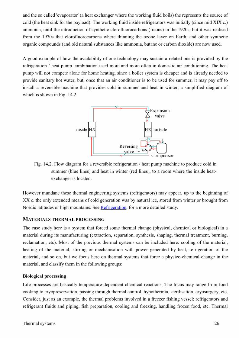
Thermal systems 26
and the so called 'evaporator' (a heat exchanger where the working fluid boils) the represents the source of cold (the heat sink for the payload). The working fluid inside refrigerators was initially (since mid XIX c.) ammonia, until the introduction of synthetic clorofluorocarbons (freons) in the 1920s, but it was realised from the 1970s that clorofluorocarbons where thinning the ozone layer on Earth, and other synthetic organic compounds (and old natural substances like ammonia, butane or carbon dioxide) are now used. A good example of how the availability of one technology may sustain a related one is provided by the refrigeration / heat pump combination used more and more often in domestic air conditioning. The heat pump will not compete alone for home heating, since a boiler system is cheaper and is already needed to provide sanitary hot water, but, once that an air conditioner is to be used for summer, it may pay off to install a reversible machine that provides cold in summer and heat in winter, a simplified diagram of which is shown in Fig. 14.2.
Fig. 14.2. Flow diagram for a reversible refrigeration / heat pump machine to produce cold in
summer (blue lines) and heat in winter (red lines), to a room where the inside heat-exchanger is located.
However mundane these thermal engineering systems (refrigerators) may appear, up to the beginning of XX c. the only extended means of cold generation was by natural ice, stored from winter or brought from Nordic latitudes or high mountains. See Refrigeration, for a more detailed study.
MATERIALS THERMAL PROCESSING The case study here is a system that forced some thermal change (physical, chemical or biological) in a material during its manufacturing (extraction, separation, synthesis, shaping, thermal treatment, burning, reclamation, etc). Most of the previous thermal systems can be included here: cooling of the material, heating of the material, stirring or mechanisation with power generated by heat, refrigeration of the material, and so on, but we focus here on thermal systems that force a physico-chemical change in the material, and classify them in the following groups:
Biological processing
Life processes are basically temperature-dependent chemical reactions. The focus may range from food cooking to cryopreservation, passing through thermal control, hypothermia, sterilisation, cryosurgery, etc. Consider, just as an example, the thermal problems involved in a freezer fishing vessel: refrigerators and refrigerant fluids and piping, fish preparation, cooling and freezing, handling frozen food, etc. Thermal
Thermal systems 27
processes in biological materials are usually dealt as a separate subject from materials processing (that are usually assumed non-living).
Chemical processing
Main processes are: ore reduction (to get the raw elements from the natural compounds), distillation (crude oil, coal, air, seawater), synthesis (ammonia, explosives), reforming (e.g. to get hydrogen or methanol from natural gas and water-vapour), thermal treatments (tempering, annealing), incineration (burning to get rid of the bulk), reclamation (recycling), etc.
Physical processing
One may further split these processes to focus on metals, semiconductors, ceramics, polymers and composites, but most processes are generic to all materials, as melting and casting, crystal growth and purification, machining, shaping, cutting and welding, drying and humidification (including air conditioning), etc. Consider, just as an example, the thermal problems involved in drilling (from boring a piece of wood with a small 500 W hand-drill, to boring underground tunnels with a large 2 MW tunneller): heat dissipation, heat transfer, cutting-edge wear, surface annealing. Materials thermal processing is achieved by somehow heating the system by what may be called a thermal actuator: a flame, an electric resistance, an electric arc, a laser beam, a plasma jet, an electron beam, an ultrasonic vibration, etc. If the heating must be applied to the whole material, a furnace is used. Monitoring is achieved by thermal sensors, either intrusive or at a distance like with radiometric thermometers, with the objective to analyse the thermal fields (temperatures and heat fluxes) or to control the whole process. It is clear that thermal analysis of materials processing is an interdisciplinary field where knowledge is required not only of thermal aspects (thermodynamic laws, heat and mass transfer, thermal properties), but of the chemical, structural or electric processes and properties being modified by temperature.
TYPE OF PROBLEMS This chapter aimed at presenting an overview of the vast area of thermal systems, i.e. it is basically descriptive, and the actual analysis of them is postponed to subsequent chapters, Thus, no problems are here proposed, although some conceptual exercises might be included, of the type: indicate several different means to heat a system, or to generate mechanical power from a fuel, or to generate electricity, or to generate cold, or to separate a mixture of gases or liquids, and so on. Back (Index),