thermal shock capabilities of infrared dome materials€¦ · thermal shock capabilities of...
TRANSCRIPT

JEFFREY S. LIN and LOUIS B. WECKESSER
THERMAL SHOCK CAPABILITIES OF INFRARED DOME MATERIALS
The thermal shock capabilities of infrared-transmitting materials must be known to design the infrared windows incorporated in many advanced air defense missile systems. This article describes a combined experimental and analytical investigation undertaken to provide the knowledge and tools necessary to design infrared windows. The experimental temperature and stress data obtained from a unique test facility at APL match well with the computer models developed.
INTRODUCTION
Many advanced air defense missile systems now being developed use an infrared (IR) seeker to home in on their targets. The high speeds at which these missiles travel create a severe aerothermal environment that must be withstood by the windows that protect the IR seekers. The high heat fluxes experienced during flight induce steep temperature gradients that can cause thermal shock failure. An assessment of the ability of candidate IR window materials to withstand thermal shock is necessary to design JR seeker systems.
In response to this need, the APL Aerothermal/IR Test Facility has conducted a series of [R dome thermal shock tests. Fifty-one tests have been performed on eight different IR window materials to find the approximate thermal shock limits for each. The materials tested were hotpressed (HP) spinel , hot-isostatic-pressed (HIP) spinel, yttria, lanthana-doped yttria, ALON (a proprietary ceramic composed of aluminum, oxygen , and nitrogen) , germania glass, zinc sulfide, and sapphi re.
Hydrogen C:::::~eEE!Th. Air heater
Computer models were also developed to predict the thermostructural response of nose-mounted hemispheric IR seeker windows to supersonic flight. The analytical approach is validated by a comparison of these predictions with the measured temperature and strain data from the tests in the Aerothermal/IR Test Faci l ity. This analytical capabili ty can be used subsequently in the design of production IR seeker systems.
TEST CONFIGURATION AND PROCEDURE
The APL Aerothermal/IR Test Facility I is located in the W. H. Avery Propulsion Research Laboratory. In the facility (Fig. 1), a large a ir supp ly is di scharged into the hydrogen heater, where hydrogen is burned directly in the airstream, heating the air to extremely high temperatures. This heated air is routed through a water-cooled Mach 5 nozzle to a test cabin where models can be injected into the supersonic airstream. Figure 2 shows the test cabin,
Mach 5 nozz le
Laser infrared source and instrumentation
Opt ical bench
Figure 1. The APL Aerothermal/infrared Test Facil ity.
John s Hopkins APL Technical Diges/. Volume /3. Number 3 (1992)
Infrared dome and sensor test unit
Water-cooled diffuser
Exhaust
379
J. S. Lin (fnd L. B. Weckesser
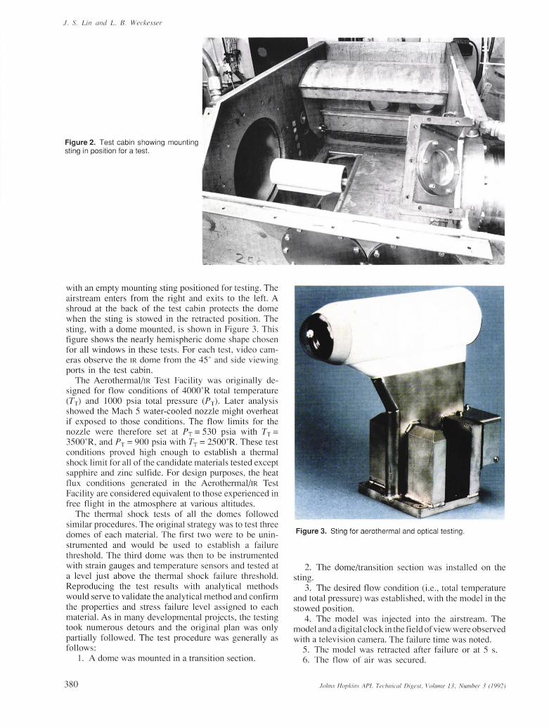
Figure 2. Test cabin showing mounting sting in position for a test.
with an empty mounting sting positioned for testing. The airstream enters from the right and ex its to the left. A shroud at the back of the test cabin protects the dome when the sting is stowed in the retracted position. The sting, with a dome mounted, is shown in Figure 3. This figure shows the nearly hemispheric dome shape chosen for all windows in these tests. For each test, video cameras observe the IR dome from the 45" and side viewing ports in the test cabin.
The Aerothermal/IR Test Facility was originally designed for flow conditions of 40000R total temperature CTT) and 1000 psia total pressure CPT) ' Later analysis showed the Mach 5 water-cooled nozzle might overheat if exposed to those conditions. The flow limits for the nozzle were therefore set at PT = 530 psia with TT = 3500o R, and PT = 900 psia with TT = 2500o R. These test conditions proved hi gh enough to establish a thermal shock limit fo r all of the candidate material s tested except sapphire and zinc sulfide. For design purposes, the heat flux conditions generated in the Aerothermal/IR Test Facility are considered equivalent to those experienced in free flight in the atmosphere at various altitudes.
The thermal shock tests of all the domes followed similar procedures. The original strategy was to test three domes of each material. The first two were to be uninstrumented and would be used to es tabli sh a failure threshold. The third dome was then to be instrumented with strain gauges and temperature sensors and tested at a level just above the them1al shock failure thresho ld. Reproducing the test results with analytical methods would serve to validate the analytical method and confirm the properties and stress failure level ass igned to each materi al. As in many developmental projects, the testing took numerous detours and the Oliginal plan was only parti ally followed. The test procedure was generally as fo llows:
I. A dome was mounted in a transition section.
380
Figure 3. Sting for aerothermal and optical testing.
2. The dome/transition section was installed on the sting.
3. The desired flow condition (i.e ., total temperature and total pressure) was establi shed, with the model in the stowed position.
4. The model was injected into the airstream. The model and a digital clock in the field of view were observed with a television camera. The failure time was noted.
5. The model was retrac ted after failure or at 5 s. 6. The flow of air was secured.
Johlls H opkills APL Techllical Digesl . VO/llme J3. NU/1lber 3 (1992)
Earlier analysis had shown that peak thermal stress would occur within the first 2 s of exposure, so the maximum time in the airstream was set at 5 s. With thi s approach, a relatively low-temperature flexible attachment could be used to support the domes during testing.
INFRARED DOME A TT ACHMENT Early in the program, considerable attention was given
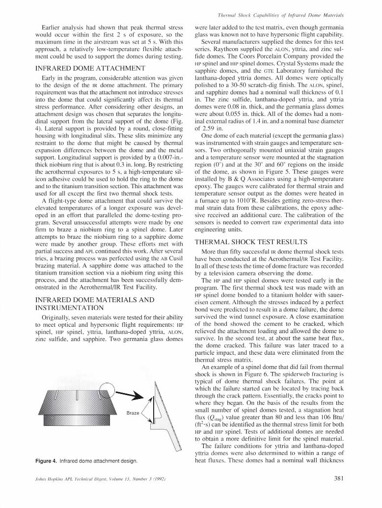
to the design of the IR dome attachment. The primary requirement was that the attachment not introduce stresses into the dome that could significantly affect its thermal stress performance. After considering other designs, an attachment design was chosen that separates the longitudinal support from the lateral support of the dome (Fig. 4). Lateral support is provided by a round, close-fitting housing with longitudinal slits. These slits minimize any restraint to the dome that might be caused by thermal expansion differences between the dome and the metal support. Longitudinal support is provided by a 0.007-in.thick niobium ring that is about 0.3 in. long. By restricting the aerothennal exposures to 5 s, a high-temperature silicon adhesive could be used to hold the ring to the dome and to the titanium transition section. This attachment was used for all except the first two thermal shock tests.
A flight-type dome attachment that could survive the elevated temperatures of a longer exposure was developed in an effort that paralleled the dome-testing program. Several unsuccessful attempts were made by one firm to braze a niobium ring to a spinel dome. Later attempts to braze the niobium ring to a sapphire dome were made by another group. These efforts met with partial success and APL continued th is work. After several tries, a brazing process was perfected using the AB Cusil brazing material. A sapphire dome was attached to the titani um transition section via a niobium ring using this process , and the attachment has been successfully demonstrated in the Aerothermal/IR Test Faci lity.
INFRARED DOME MATERIALS AND INSTRUMENTATION
Originally, seven materials were tested for their abi li ty to meet optical and hypersonic flight requirements: HP
spinel, HIP spinel , yttria, lanthana-doped yttria, ALON,
zinc su lfide, and sapphire. Two germania glass domes
Figure 4. Infrared dome attachment design.
Johns Hopkins A PL Tecllllical Digest. Volume 13 . Number 3 (/992)
Thermal Shock Capahilities of Infrared Dome Materials
were later added to the test matrix , even though germania g lass was known not to have hypersonic flight capab ility.
Several manufacturers supplied the domes for this test series. Raytheon supplied the ALO , yttria, and zinc sulfide domes. The Coors Porcelain Company provided the HP spinel and HIP spinel domes. Crystal Systems made the sapphire domes, and the GTE Laboratory furni shed the lanthana-doped yttria domes. All domes were optically polished to a 30-50 scratch-dig finish. The ALO , spinel , and sapphire domes had a nominal wall thickness of 0.1 in. The zinc sulfide, lanthana-doped yttria, and yttria domes were 0.08 in. thick, and the germania glass domes were about 0.055 in. thick. All of the domes had a nominal external radius of 1.4 in. and a nominal base diameter of 2.59 in.
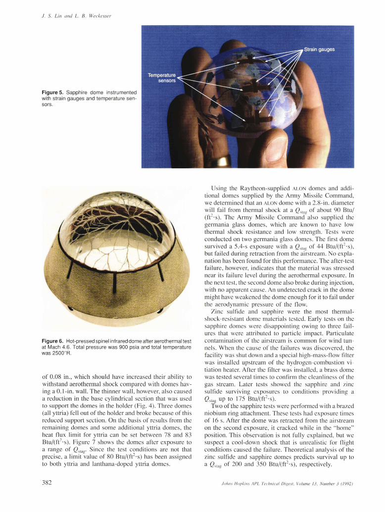
One dome of each material (except the germania glass) was instrumented with strain gauges and temperature sensors. Two orthogonally mounted uniaxial strain gauges and a temperature sensor were mounted at the stagnation region (0°) and at the 30° and 60° regions on the inside of the dome, as shown in Figure 5. These gauges were installed by B & Q Associates using a high-temperature epoxy. The gauges were calibrated for thermal strain and temperature sensor output as the domes were heated in a furnace up to 10 10oR. Besides getting zero-stress thermal strain data from these calibrations, the epoxy adhesive received an additional cure. The calibration of the sensors is needed to convert raw experimental data into engineering units.
THERMAL SHOCK TEST RESULTS lVlore than fifty successful IR dome thermal shock tests
have been conducted at the Aerothermal/IR Test Facility. In all of these tests the time of dome fracture was recorded by a television camera observing the dome.
The HP and HIP spinel domes were tested early in the program. The first thermal shock test was made with an HP spinel dome bonded to a titanium holder with sauereisen cement. Although the stresses induced by a perfect bond were predicted to result in a dome failure, the dome surv ived the wind tunnel exposure. A close examination of the bond showed the cement to be cracked, which relieved the attachment loading and allowed the dome to survive. In the second test, at about the same heat flux, the dome cracked. This failure was later traced to a particle impact, and these data were eliminated from the the rmal stress matrix.
An example of a spinel dome that did fail from thermal shock is shown in Figure 6. The spiderweb fracturing is typical of dome thermal shock failures. The point at which the failure started can be located by trac ing back through the crack pattern. Essentially, the cracks point to where they began. On the basis of the resu lts from the small number of spinel domes tested, a stagnation heat flux (Qslag) value greater than 80 and less than 106 Btu/ (ft2 ·s) can be identified as the thermal stress limit for both HP and HIP spinel. Tests of additional domes are needed to obtain a more definitive limit for the spinel material.
The failure conditions for yttria and lanthana-doped yttria domes were also determined to within a range of heat fluxes. These domes had a nominal wall thickness
381
1. S. Lin and L. B. Weckesser
Figure 5. Sapph ire dome instrumented with strain gauges and temperature sensors.
Figure 6. Hot-pressed spinel infrared dome after aerothermal test at Mach 4.6. Total pressure was 900 psia and total temperature was 2500o R.
of 0.08 in., which should have increased their ability to withstand aerothermal shock compared with domes having a O.I-in. wall. The thinner wall, however, also caused a reduction in the base cylindrical section that was used to support the domes in the holder (Fig. 4) . Three domes (all yttria) fell out of the holder and broke because of this reduced support section. On the basis of results from the remaining domes and some additional yttria domes, the heat flux limit for yttria can be set between 78 and 83 Btu/(ft2 ·s). Figure 7 shows the domes after exposure to a range of Q stao • Since the test conditions are not that precise, a limit ~alue of 80 Btu/(ft2·s) has been assigned to both yttria and lanthana-doped yttria domes.
382
Using the Raytheon-supplied ALON domes and additional domes supplied by the Army Missile Command, we determined that an ALON dome with a 2.8 -in. diameter will fa il from thermal shock at a Q Slag of about 90 Btu/ (ft2 ·s). The Army Missile Command also supplied the germania glass domes, which are known to have low thermal shock resistance and low strength. Tests were conducted on two germania glass domes. The first dome survived a 5.4-s exposure with a Q Slag of 44 Btu/(ft2·s), but failed during retraction from the airstream. No explanation has been found for this performance. The after-test failure, however, indicates that the material was stressed near its fa ilure level during the aero thermal exposure. In the next test, the second dome also broke during injection, with no apparent cause. An undetected crack in the dome might have weakened the dome enough for it to fail under the aerodynamic pressure of the flow.
Zinc sulfide and sapphire were the most thermalshock-resistant dome materials tested. Early tests on the sapphire domes were disappointing owing to three fai lures that were attributed to particle impact. Particulate contamination of the airstream is common for wind tunnels. When the cause of the fa ilures was discovered, the facility was shut down and a special high-mass-flow filter was installed upstream of the hydrogen-combustion vi tiation heater. After the filter was installed, a brass dome was tested several times to confirm the cleanliness of the gas stream. Later tests showed the sapphire and zinc sulfide surviving exposures to conditions providing a Q Sla o up to 175 Btu/(ft2 ·s).
. Two of the sapphire tests were performed with a brazed niobium ring attachment. These tests had exposure times of 16 s. After the dome was retracted from the airstream on the second exposure, it cracked while in the "home" position. This observation is not fully explained, but we suspect a coo l-down shock that is unrealistic for f light conditions caused the failure. Theoretical analysis of the zinc sulfide and sapphire domes predicts survival up to a Q Slag of 200 and 350 Btu/(ft2·s), respectively.
.I 0 hIlS HopkiliS APL Tcchllical Digesi. Voillme J 3. Numher 3 (/992)
Thermal Shock Capabilities of Infrared Dome Materials
B
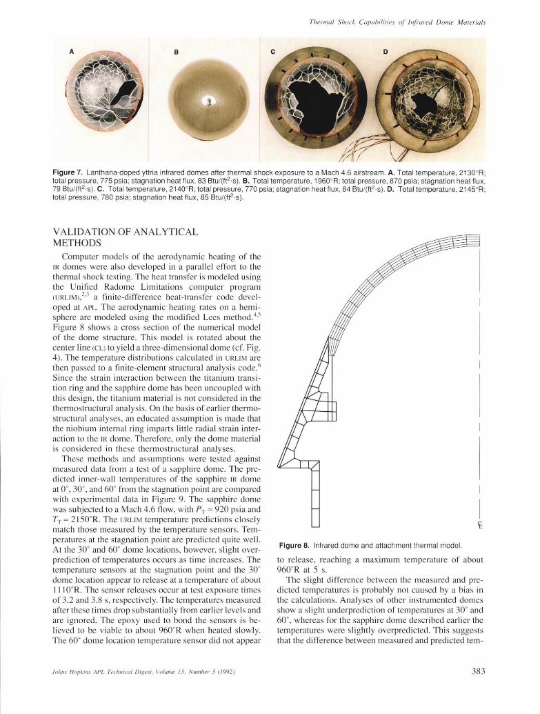
Figure 7. Lanthana-doped yttria infrared domes after thermal shock exposure to a Mach 4.6 airstream. A. Total temperature, 2130oR; total pressure, 775 psia; stagnation heat flux , 83 Btu/(ft2· S}. B. Total temperature , 1960oR; total pressure , 870 psia; stagnation heat flux, 79 Btu/(ft2 ·S}. C. Total temperature , 2140oR; total pressure , 770 psia ; stagnation heat flux , 84 BtU/(ft2· S}. D. Total temperature, 2145°R; total pressure , 780 psia; stagnation heat flux, 85 BtU/(ft2 ·S}.
V ALIDATION OF ANALYTICAL METHODS
Computer models of the aerodynamic heating of the IR domes were also developed in a parallel effort to the thermal shock testing. The heat transfer is modeled using the Unified Radome Limitations computer program (UR LIM ),2J a finite-difference heat-transfer code developed at APL. The aerodynamic heating rates on a hemisphere are modeled using the modified Lees method. 4
,5
Figure 8 shows a cross section of the numerical model of the dome structure. This model is rotated about the center line (CL) to yield a three-dimensional dome (cf. Fig. 4). The temperature distributions calculated in UR LIM are then passed to a finite-element structural analysis code.6
Since the strain interaction between the titanium transition ring and the sapphire dome has been uncoupled with this design , the titanium material is not considered in the thermostructural analysis. On the basis of earlier thermostructural analyses, an educated assumption is made that the niobium internal ring imparts little radial strain interaction to the IR dome. Therefore, only the dome material is considered in these thermostructural analyses.
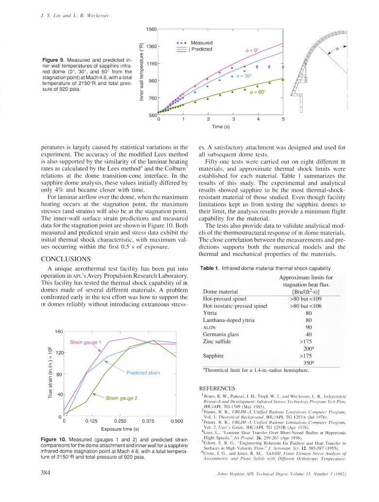
These methods and assumptions were tested against measured data from a test of a sapphire dome. The predicted inner-wall temperatures of the sapphire IR dome at 0°, 30°, and 60° from the stagnation point are compared with experimental data in Figure 9. The sapphire dome was subjected to a Mach 4.6 flow, with PT ;:::: 920 psia and TT ;:::: 2150°R. The URLIM temperature predictions closely match those measured by the temperature sensors. Temperatures at the stagnation point are predicted quite well. At the 30° and 60° dome locations, however, slight overprediction of temperatures occurs as time increases . The temperature sensors at the stagnation point and the 30° dome location appear to release at a temperature of about ] 11 OOR. The sensor releases occur at test exposure times of 3.2 and 3.8 s, respectively. The temperatures measured after these times drop substantially from earlier levels and are ignored. The epoxy used to bond the sensors is believed to be viable to about 9600 R when heated slowly. The 60° dome location temperature sensor did not appear
.Iolil/s Hopkil/s A PL Teclillical Digest . Volume /3 . Nllmber 3 (1992)
Figure 8. Infrared dome and attachment thermal model.
to release, reaching a maximum temperature of about 960 0 R at 5 s.
The slight difference between the measured and predicted temperatures is probably not caused by a bias in the calculations. Analyses of other instrumented domes show a slight underprediction of temperatures at 30° and 60°, whereas for the sapphire dome described earlier the temperatures were slightly overpredicted. This suggests that the difference between measured and predicted tem-
383
1. S. Lin and L. B. Weckesser
1560 ~----~------~------~------~------.
[ 1360 • • • Measured
} Predicted
Figure 9. Measured and predicted inner-wai l temperatures of sapphire infrared dome (0°, 30°, and 60° from the stagnation point) at Mach 4.6, with a total temperature of 2150 0 R and total pressure of 920 psia.
CD :J co Q) 0.. E 2
peratures is largely caused by statistical variations in the experiment. The accuracy of the modified Lees method is also supported by the similarity of the laminar heating rates as calculated by the Lees method4 and the Colburn 7
relations at the dome transition-cone interface. In the sapphire dome analysis, these values initially differed by on ly 4% and became closer with time.
For laminar airflow over the dome, when the maximum heating occurs at the stagnation point, the maximum stresses (and strains) will also be at the stagnation point. The inner-wall surface stra in predictions and measured data for the stagnation point are shown in Figure 10. Both measured and predicted strain and stress data ex hibit the initial thermal shock characteristic, with maximum values occurring within the first O.S s of exposure.
CONCLUSIONS A unique aerothermal test faci lity has been put into
operation in APL'S Avery Propulsion Research Laboratory. This fac ility has tested the thermal shock capability of IR
domes made of several different materials. A problem confronted early in the test effort was how to support the IR domes reliably without introducing extraneous stress-
160
<D 0 120 x
--:-c
0.::::
. ~ 80 c
.~
Ui CD ::>
f-'=
0 0 0.125
Predicted strain
Strain gauge 2
0.250
Exposure time (s)
0.375 0.500
Figure 10. Measured (gauges 1 and 2) and predicted strain comparisons for the dome attachment and inner wal l for a sapphire infrared dome stagnation point at Mach 4.6, with a total temperature of 2150 0 R and total pressure of 920 ps ia.
384
2 3 4 5
Time (s)
es . A atisfactory attachment was designed and used for a ll subseq uent dome tests.
Fifty-one tests were carried out on eight different IR
materials, and approximate thermal shock limits were estab li shed for each material. Table 1 summarizes the results of this study. The experimental and analytical results showed sapphire to be the most thennal-shockresistant material of those studied. Even though facility limitations kept us from testi ng the sapphire domes to thei r limit, the analysis results provide a minimum fl ight capability for the material.
The tests also provide data to validate analytical models of the thermostructural response of JR dome material s. The close correlation between the measurements and predictions supports both the numerical model s and the thermal and mechanical properties of the material s.
Table 1. Infrared dome material thermal shock capabil ity.
Dome material Hot-pressed spinel Hot-isostatic-pre ed pinel Yttria Lanthana-doped yttria ALO
Germania glass Zinc sulfide
Sapphire
Approximate limits for stagnation heat flux
[Btu/(ft2·s)] >SO but <109 >SO but <106
SO SO 90 40
> 175 200a
>175 350a
aTheoretical limit fo r a l.4-in .-radius hemi phere .
REFERENCES I Brun s, R. W., Panesci , J. H., Tropf, W. J. , and Weckesser, L. B., Independent Research and Development: Infrared Sensor Technology Program Tesl Plal/, JH U/A PL TG- 1349 (May 1985).
2 Frazer, R. K. , UR LlM- A Unified Radome Limilaliol/s Complller Program. Vol. I. Theoretical Background. JH /A PL TG 1293A (Jul 1976).
} Frazer, R. K. , URLlM-A Unified Radome Limitaliol1s Computer Program, Vol. 2, User's Gllide, JHUjA PL TG 1293B (A pr 1978)
4Lees, L. , " Laminar Heat Transfer Over Blunt- losed Bodies at Hypersonic Fli ght Speeds." .let ProPlIl. 26 , 259-267 (Apr 1956).
SEcken , E. R. G. , " Engineering Re lations for Friction and Heat Transfe r to Surfaces in Hi gh Veloc it y Flow," .I . Aeronauf. Sci. 12, 585- 587 ( 1955).
6Crose, J. G .. and Jones, R. M. , SAASIII. Finite Elemert! SIt'ess Analysis of' Axisymmelric and Plane Solids willi Differert! Orrhotropic Temperature-
Jolins Hopkins APL Technical Digesl. Vo lllme 13 , Numher 3 (1992)
Dependelll Material Properties ill Tellsioll alld Compressioll." TR-0059 (S68 16-53 )- I , Aerospace Corporati on, Los Angeles , Calif. (22 lu n 197 1).
7Co lburn , A. P .. " A Method o f Corre latin g Fo rced Convec ti on Heat T ransfer Dat a and a Comparison with Fluid Fri cti on," Trans. Am . Inst . Cherll . Eng. 29 , 174-2 10 ( 1933) .
THE AUTHORS
JEFFREY S. LIN received a B.S.E. degree in mechanical/ae rospace engineering from Princeton University in 1986 and an M.S. in computer science in 1989 from The Johns Hopkins University, where he is currently pursuing a Ph.D. in materials science and engineering. Mr. Lin has been in the Engineering Group of the Aeronautics Department since joining APL in 1986. While with the Thermal Analys is Section , he analyzed the ae rothermal heating and rain erosion of missile structures. He is currently in the Appli ed Inte lligent Systems Section , where he is appl ying neu
ral networks and expert system technologies to the fi e lds of di agnosti cs and nondestructive evaluation . He is a member of Tau Beta Pi and the American Institute of Aeronautics and Astronauti cs.
.fohns Hopkins APL Tecllllical Digest. Volume 13 . Number 3 (/ 992)
Thermal Shock Capahilities of inji'ared Dome Materials
AC K O WL EDG M E T: This work was sponsored by Barry Lubin , NAVSEA (PM S 422- 16). Spec ia l recognition is g iven to John Ecker, l ames Panesc i, and Charl es Walton for the ir technical contributi ons to thi s program.
Lo u rs B. WECKESSER received B.S. and M.S. degrees in mechanical engineering from the Uni versity of Maryland. He has been empl oyed at APL since June 1952 in the Engineering Group of the Aeronautics Department. As Supervi sor of the Thermal Analys is and Test Section of that group , he has di rec ted work on the Talos, Terrier, ALBIS, Standard Mi ss ile, SCRAM, AWADM, and , most recently, EN K
mi ss ile programs. During the past 20 years Mr. Weckesser has been a leader in the mechanical design aspects of supersonic and hypersonic homing miss ile radome tech
nology. He was the author of a chapter on 'Thelmal-Mechanica l Des ign Principles" in the Radome Engineering Handbook. Since 1979, he has conducted an intensive short course on radomes with Edward Joy of the Georgia Institute of Technology, which has been presented at several loca ti ons in this country and in Zurich, Switzerland.
385