thermal gas mass flowmeter · 2017-11-01 · thermal gas mass flow meter is designed on the basis...
TRANSCRIPT
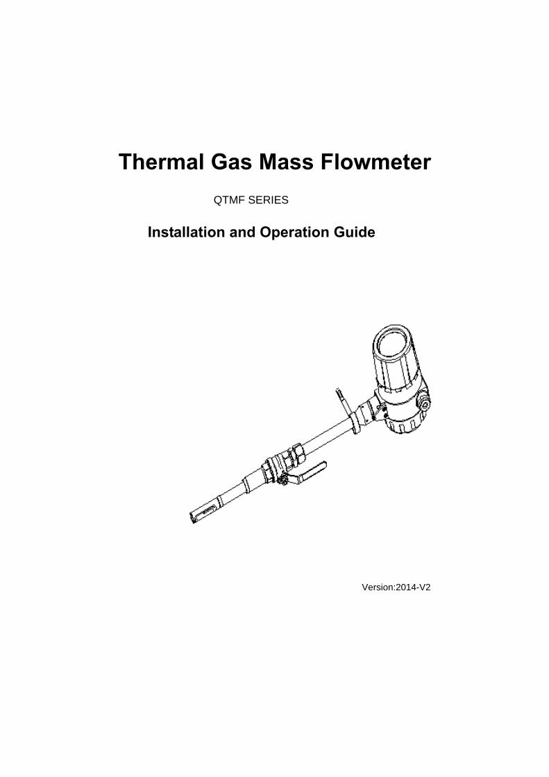
Thermal Gas Mass Flowmeter
Installation and Operation Guide
Installation and Operation Guide
Version:2014-V2
QTMF SERIES

CONTENTS
Safety Information ............................................................................................................. 1
Part 1 Introduction ............................................................................................................. 4
Part 2 Specifications .......................................................................................................... 6
Part 3 Mechanical Construction ........................................................................................ 8
3.1 Appearance .......................................................................................................... 8
3.2 Dimensions .......................................................................................................... 9
Part 4 Wirings ................................................................................................................... 11
4.1 Instruction of Sensor Wirings .............................................................................. 11
4.2 Instruction of Transmitter Wirings ....................................................................... 11
4.3 The Wirings of Power Supply ............................................................................. 12
Part 5 Installation ............................................................................................................ 14
5.1 Installation Position ............................................................................................ 14
5.2 Pipework requirements ...................................................................................... 16
5.3 Installation Steps ................................................................................................ 17
Part 6 Operation and Programming ................................................................................ 19
6.1 Display ............................................................................................................... 19
6.2 Parameters Setup .............................................................................................. 20
6.2.1 Main Menu ............................................................................................... 20
6.2.2 Setup Menu ............................................................................................. 20
6.2.3 Unit Display ............................................................................................. 21
6.2.4 Self-Checking .......................................................................................... 21
6.2.5 Total Reset ............................................................................................... 21
6.2.6 Parameter Setup ...................................................................................... 22
6.2.7 Calibration ............................................................................................... 24
6.2.8 Password ................................................................................................. 26
6.2.9 Query ....................................................................................................... 27
Appendix 1 Troubleshooting and Repair ......................................................................... 28
Appendix 2 The Density and Conversion Coefficient of Common Gas ........................... 30
Appendix 3 Upper Range Value of Common Gas ........................................................... 33

Page 1 of 34
Safety Information
Please have a safekeeping of this manual and together with the instrument after reading.
Please pass this manual to technical department of end user to keep.
This manual classifies important grade of safety attentions by Caution and Warning.
This manual contents the following icons:
Indicates safety attentions which are dangerous.
Indicates safety attentions which are.needed to pay attention to.
Indicates safety attentions which are.forbidden.
Select explosion-proof instrument for explosive environment application
Confirm whether the nameplate of instrument has the identifiers of explosion-proof
certification and temperature class, the instrument can’t be used in explosive environment
without those identifiers.
The explosion-proof temperature class of instrument must meet the
explosion-proof and temperature of environmental requirements on site
When the instrument is in used explosion-proof environment, make sure that the
explosion-proof certification and temperature class of instrument meet to the requirements
Caution
Error operation in case of ignoring the tips might cause the personal injury,
or damage to the instrument and property.
Thank you for purchasing our quality Thermal Gas Mass Flowmeter with independent research and
development.
We have written this guide to provide the persons responsible for the installation, operation and
maintenance of your flow meter with the product specific information they will need.
In order to prevent damage to instrument and make the instrument in the best performance and stable
operation, please read this manual thoroughly before installation.
Warning Error operation in case of ignoring the tips might cause the personal injury
or major accident.

Page 2 of 34
on site.
No opening while working in explosive environment
Before wirings, please power instrument off.
The protection class of instrument must meet the working condition
requirements on site
The requirement of protection class on site should be under, or the same as the protection
class of instrument to ensure that the instrument is working fine.
Confirm the power type
Customers can select the power type: 220VAC or 24VDC (Please state it when ordering).
Please confirm the power type before installation.
Confirm the working environment of instrument and medium temperature
The environment on site and the maximum medium temperature should be under the
nominal value of instrument. (The details of nominal value are shown in Part 2
Specifications.)
No hot-tapped installation and maintenance while the medium temperature is
too high
When temperature of measuring medium is higher than the temperature that human can
bear, or higher than the temperature of possible danger, should shut down or do cooling
process to reach a safety temperature, and then do hot-tapped operation. If there are no
conditions to do hot-tapped operation, should shut down to avoid dangers.
Confirm the ambient pressure of instrument and medium pressure
The ambient pressure on site and the maximum medium pressure should be under the
nominal value of instrument. (The details of nominal value are shown in Part 2
Specifications.)
No hot-tapped installation and maintenance while the medium pressure is too
high
When absolute pressure of measuring medium is higher than 5 times standard
atmospheric pressure, or higher than the pressure of possible danger, should shut down

Page 3 of 34
or do reducing pressure to reach a safety pressure, and then do hot-tapped operation. If
there are no conditions to do hot-tapped operation, should shut down to avoid dangers.
Extra requirements of special medium
The properties of some gas are special, it is needed to order special product, please
check the manual of special product thoroughly to make sure whether it meets the
requirements on site before installation.
No hot-tapped installation and maintenance while the medium is dangerous
gas
When the medium may cause injury to humans, no hot-tapped installation and
maintenance, should shut down or do security processing to reach a safety condition, and
then do hot-tapped operation. If there are no conditions to do hot-tapped operation, should
shut down to avoid dangers. The dangerous gases are such gas and chlorine, etc.
If doubting that the instrument in the event of failure, please do not operate it
If there are something wrong with the instrument or it had been damaged, please contact
us.
Page 4 of 34
Part 1 Introduction
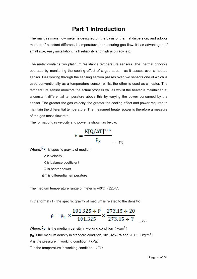
Thermal gas mass flow meter is designed on the basis of thermal dispersion, and adopts
method of constant differential temperature to measuring gas flow. It has advantages of
small size, easy installation, high reliability and high accuracy, etc.
The meter contains two platinum resistance temperature sensors. The thermal principle
operates by monitoring the cooling effect of a gas stream as it passes over a heated
sensor. Gas flowing through the sensing section passes over two sensors one of which is
used conventionally as a temperature sensor, whilst the other is used as a heater. The
temperature sensor monitors the actual process values whilst the heater is maintained at
a constant differential temperature above this by varying the power consumed by the
sensor. The greater the gas velocity, the greater the cooling effect and power required to
maintain the differential temperature. The measured heater power is therefore a measure
of the gas mass flow rate.
The format of gas velocity and power is shown as below:
……(1)
Where: is specific gravity of medium
V is velocity
K is balance coefficient
Q is heater power
Δ T is differential temperature
The medium temperature range of meter is -40~220.
In the format (1), the specific gravity of medium is related to the density:
……(2)
Where: is the medium density in working condition(kg/m3)
ρn is the medium density in standard condition, 101.325kPa and 20 (kg/m3)
P is the pressure in working condition(kPa)
T is the temperature in working condition ()

Page 5 of 34
In the formats (1) and (2), there is a certain functional relationship between the velocity
and pressure in working condition, medium density, the temperature in working condition.
Due to the sensor temperature is always 30 higher than the medium temperature
(environment temperature), and the meter adopts method of constant differential
temperature, therefore the meter do not need to do temperature and pressure
compensation in principle.
Page 6 of 34
Part 2 Specifications
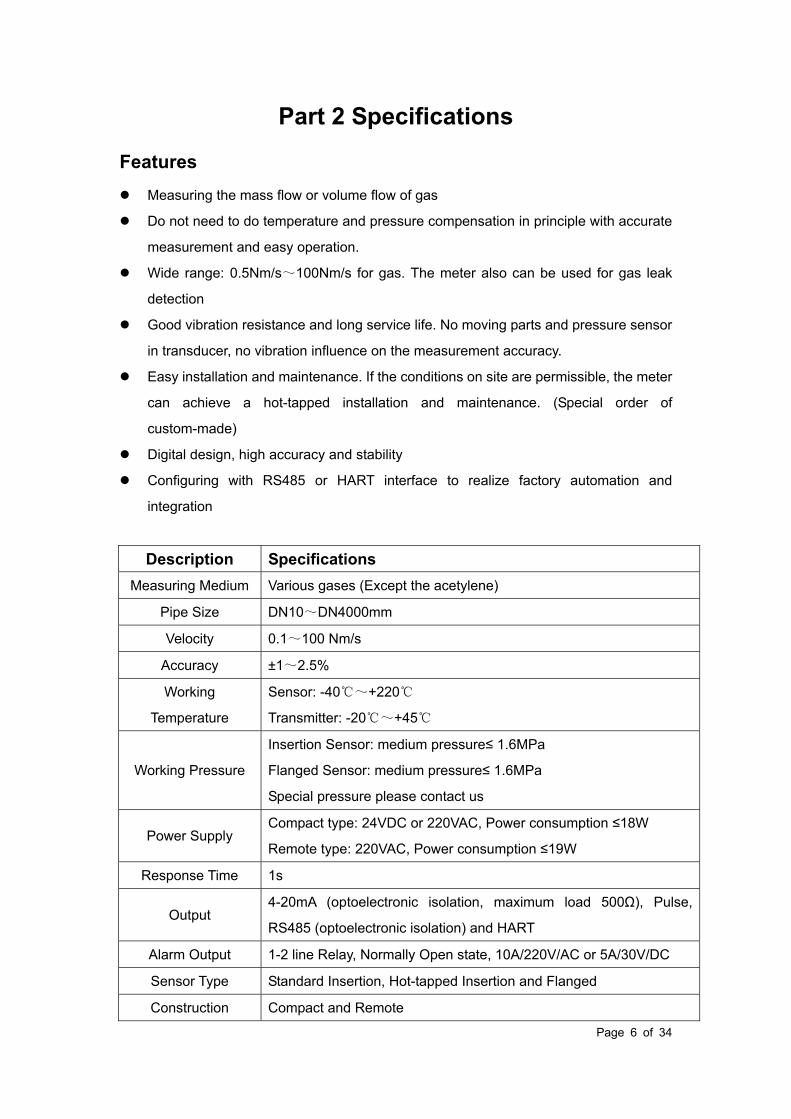
Features
Measuring the mass flow or volume flow of gas
Do not need to do temperature and pressure compensation in principle with accurate
measurement and easy operation.
Wide range: 0.5Nm/s~100Nm/s for gas. The meter also can be used for gas leak
detection
Good vibration resistance and long service life. No moving parts and pressure sensor
in transducer, no vibration influence on the measurement accuracy.
Easy installation and maintenance. If the conditions on site are permissible, the meter
can achieve a hot-tapped installation and maintenance. (Special order of
custom-made)
Digital design, high accuracy and stability
Configuring with RS485 or HART interface to realize factory automation and
integration
Description Specifications
Measuring Medium Various gases (Except the acetylene)
Pipe Size DN10~DN4000mm
Velocity 0.1~100 Nm/s
Accuracy ±1~2.5%
Working
Temperature
Sensor: -40~+220
Transmitter: -20~+45
Working Pressure
Insertion Sensor: medium pressure≤ 1.6MPa
Flanged Sensor: medium pressure≤ 1.6MPa
Special pressure please contact us
Power Supply Compact type: 24VDC or 220VAC, Power consumption ≤18W
Remote type: 220VAC, Power consumption ≤19W
Response Time 1s
Output 4-20mA (optoelectronic isolation, maximum load 500Ω), Pulse,
RS485 (optoelectronic isolation) and HART
Alarm Output 1-2 line Relay, Normally Open state, 10A/220V/AC or 5A/30V/DC
Sensor Type Standard Insertion, Hot-tapped Insertion and Flanged
Construction Compact and Remote

Page 7 of 34
Pipe Material Carbon steel, stainless steel, plastic, etc
Display
4 lines LCD
Mass flow, Volume flow in standard condition, Flow totalizer, Date
and Time, Working time, and Velocity, etc.
Protection Class IP65
Sensor Housing
Material
SS304 or SS316

Page 8 of 34
Part 3 Mechanical Construction
3.1 Appearance
Fig. 1 Standard Insertion Flow Meter Fig. 2 Flanged Flow Meter
(Pipe size DN100-DN500) (Pipe size DN10-DN80)
Fig. 3 Hot-tapped Insertion Flow Meter
(Pipe size DN100-DN4000. Special requirements please contact us)

Page 9 of 34
The insertion sensor of compact insertion flow meter should be inserted to axis of pipe,
and the length of the insertion sensor is decided by pipe size, please confirm the pipe size
when ordering. If the insertion sensor can’t be inserted to axis of pipe, the manufacturer
will provide a calibration factor to achieve an accurate measurement.
3.2 Dimensions
Dimensions of standard insertion sensor Dimensions of hot-tapped insertion sensor
The dimensions of flanged sensor
Page 10 of 34
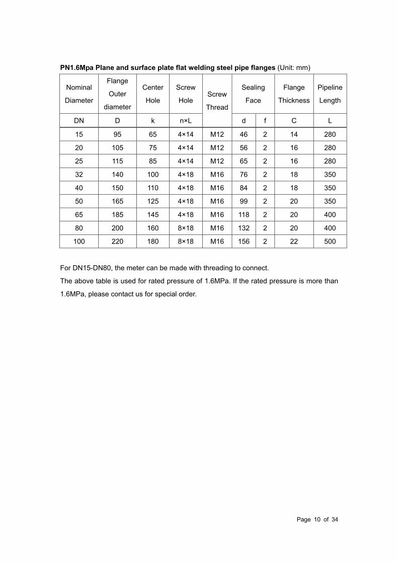
PN1.6Mpa Plane and surface plate flat welding steel pipe flanges (Unit: mm)
Nominal
Diameter
Flange
Outer
diameter
Center
Hole
Screw
Hole Screw
Thread
Sealing
Face
Flange
Thickness
Pipeline
Length
DN D k n×L d f C L
15 95 65 4×14 M12 46 2 14 280
20 105 75 4×14 M12 56 2 16 280
25 115 85 4×14 M12 65 2 16 280
32 140 100 4×18 M16 76 2 18 350
40 150 110 4×18 M16 84 2 18 350
50 165 125 4×18 M16 99 2 20 350
65 185 145 4×18 M16 118 2 20 400
80 200 160 8×18 M16 132 2 20 400
100 220 180 8×18 M16 156 2 22 500
For DN15-DN80, the meter can be made with threading to connect.
The above table is used for rated pressure of 1.6MPa. If the rated pressure is more than
1.6MPa, please contact us for special order.

Page 11 of 34
Part 4 Wirings
No operation when the meter is working
Confirm the power supply type
4.1 Instruction of Sensor Wirings
1 2 3 4
RT1 RT2 RH1 RH2
Temperature sensor (Pt1000) Heater (Pt20)
4.2 Instruction of Transmitter Wirings
Page 12 of 34
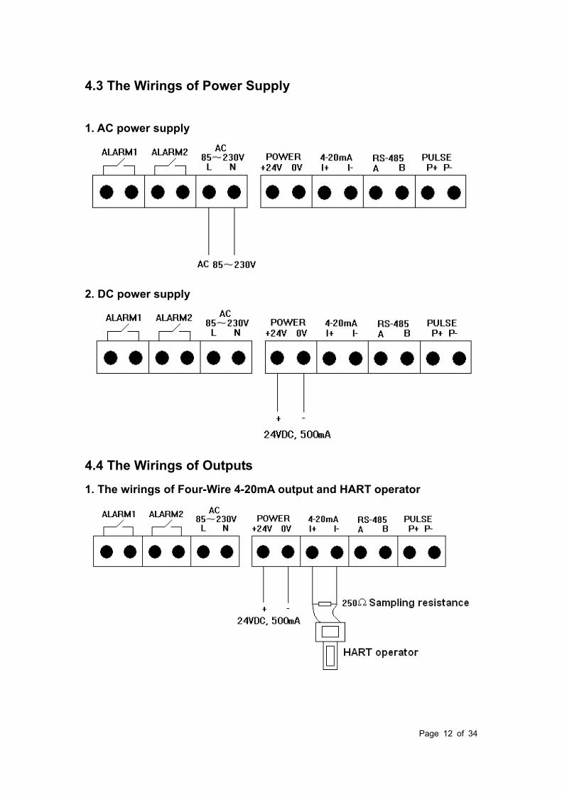
4.3 The Wirings of Power Supply
1. AC power supply
2. DC power supply
4.4 The Wirings of Outputs
1. The wirings of Four-Wire 4-20mA output and HART operator
Page 13 of 34
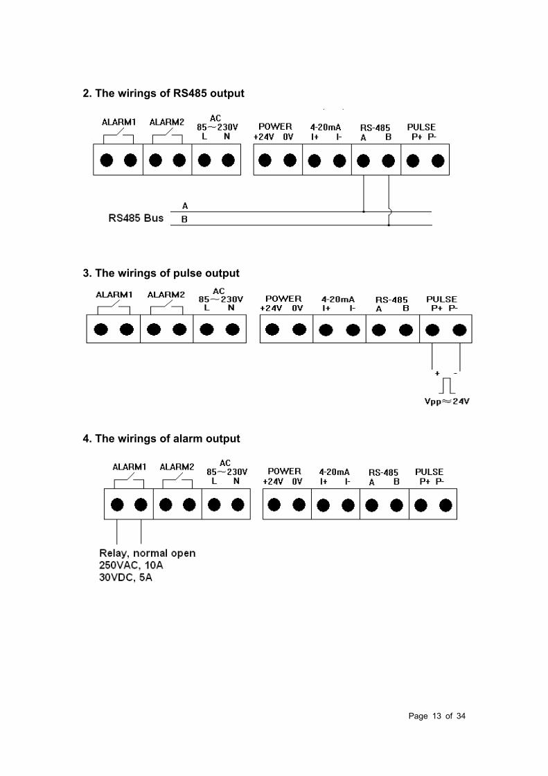
2. The wirings of RS485 output
3. The wirings of pulse output
4. The wirings of alarm output
Page 14 of 34
Part 5 Installation
5.1 Installation Position
Thermal meters require a fully developed flow profile as a prerequisite for correct flow
measurement. For this reason, please note the following points when installing the device.
Observe the recommended inlet and outlet requirements.
Good engineering practice is necessary for the associated pipe work and installation.
Ensure correct alignment and orientation of the sensor.
Take measures to reduce or avoid condensation (e.g. install a condensation trap,
thermal insulation, etc.).
The maximum permitted ambient temperatures and the medium temperature range
must be observed.
Install the transmitter in a shaded location or use a protective sun shield.
For mechanical reasons, and in order to protect the pipe, it is advisable to support
heavy sensors.
No installation in where large vibration exists
No exposure in the environment containing a lot of corrosive gas
No sharing power supply with frequency converter, electric welding machine and
other machines which can make power-line interference. If necessary, please add
power conditioner for transmitter power supply.
Thermal insulation
When the gas is very humid or saturated with water (e. g. Bio Gas), the piping and
flowmeter body should be insulated to prevent water droplets condensing on the
measuring sensor.

Page 15 of 34
a Maximum insulation height for the flanged sensor
b Maximum insulation height for the insertion sensor
The thermal dispersion principle is sensitive to disturbed flow conditions.
As a general rule, the thermal flowmeter should always be installed as far away as
possible from any flow disturbances. For further information please refer to ISO
14511.
Where two or more flow disturbances are located upstream of the meter, the
recommended inlet length for the flow disturbance causing strongest disturbance
must be used. E.g. where a valve is mounted before a bend, upstream of the
flowmeter, 50 × DN of pipe work is required from the valve to the flowmeter.
For very light gases such as Helium and Hydrogen all upstream distances should be
doubled.
The minimum recommendations for inlet and outlet runs (without flow conditioner)
are:
Flanged sensor

Page 16 of 34
1 = Reduction, 2 = Expansion, 3 = 90° elbow or T-piece, 4 = 2 × 90° elbow, 5 = 2 × 90°
elbow (3-dimensional), 6 = Control valve.
Insertion sensor
1 = Reduction, 2 = Expansion, 3 = 90° elbow or T-piece, 4 = 2 × 90° elbow, 5 = 2 × 90°
elbow (3-dimensional), 6 = Control valve or pressure regulator.
A specially designed perforated plate flow conditioner can be installed if it is not possible
to observe the inlet runs required.
5.2 Pipework requirements
Good engineering practice should be followed at all times:
Correct preparation, welding and finishing techniques
Correctly sized gaskets
Correctly aligned flanges and gaskets
Connecting pipe work should match the internal diameter of the flowmeter.
Maximum pipe diameter mismatch should not exceed:
-1 mm (0.04 inch) for diameters < DN 200 (8")
-3 mm (0.12 inch) for diameters ≥ DN 200 (8")
New installations should be free of metallic and abrasive particles to prevent damage
to the sensing elements on start-up
For further information please refer to ISO 14511.

Page 17 of 34
5.3 Installation Steps
The base of thermal flowmeter
The base of Hot-tapped insertion type The base of standard insertion type
No welding in explosive environment
Carry out the welding operation in accordance with the requirements of special
environment.
When installing, place the base on the top of pipe, and make the through-hole of base be
perpendicular to axis of pipe. The good welding location of base and welding process is as
below.
Good welding location of base
The installation of standard insertion type
Identify an appropriate location for the flow meter.
Confirm the inner diameter and wall thickness of pipe
Place the other part of meter into ball valve, and calculate the insertion depth
according to the inner diameter and wall thickness of pipe. This step doesn’t need to
screw the nut by hand.
Turn the connecting rod of sensor to make the mark direction of sensor as the same
flow direction.
According the calculated data on site, ensure the insertion depth by corresponding
Before Welding, the base should be
processed as the same as the circular arc
of pipe to ensure sealing
Page 18 of 34
calibration on the connecting rod, and then screw the nut tightly.
If the meter is horizontal installation, the display of the meter can be installed in the
direction of 90°, 180° or 270° to meet various requirements.
The installation of hot-tapped insertion type
Before installation, please conform the connection type and install fittings.
Before installation, the site must be shut down, and strictly follow the rules of factory.
Identify an appropriate location for the flow meter.
According to length requirement of meter, cut the pipe, and install the flanges and
bolts on the pipe.
Ensure the mark direction of meter is as the same flow direction, the display is
perpendicular to horizontal plane, the axis of pipeline is paralleled to horizontal plane,
the error can’t be more than ±2.5, and then fix the meter by bolts.

Page 19 of 34
Part 6 Operation and Programming
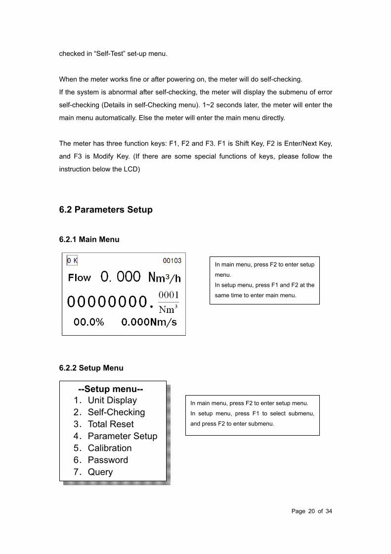
6.1 Display
The display of meter in working status is shown as below.
The prompt line:
OK: The meter can do self-checking. If the system is normal after self-checking, it will
display OK, else it will display ERR. The error information can be checked in “Self-Test”
set-up menu.
AL1: Alarm information. AL1 means path 1 alarming, and AL2 means path 2 alarming.
mA: If the current output is more than 20mA, it display mA, else it will be blank.
OV: If the operation parameters overflow, it display OV, else it will be blank.
1K: For convenience of display and read, when the total flow is more than 10 000 000, it
display 1K, and the is the display total flow multiplied by 1000.
00103: Information of communication status. The first three digits indicate meter address;
the forth digit indicates parity check (0: none; 1: odd; 2: even); and the fifty digit indicate
baud rate (0: 1200; 1: 2400; 2: 4800; 3: 9600). If the meter address is 1, no parity check,
and the baud rate is 9600, it will display “00103”.
After powering on, the meter will do self-checking. If the system is normal after
self-checking, it will display OK, else it will display ERR. The error information can be
Decimal and unit
of total flow
Medium velocity
Prompt line
Flow Rate
Total flow
Flow percentage
Function keys:
F1, f2 and f3,
Page 20 of 34
checked in “Self-Test” set-up menu.
When the meter works fine or after powering on, the meter will do self-checking.
If the system is abnormal after self-checking, the meter will display the submenu of error
self-checking (Details in self-Checking menu). 1~2 seconds later, the meter will enter the
main menu automatically. Else the meter will enter the main menu directly.
The meter has three function keys: F1, F2 and F3. F1 is Shift Key, F2 is Enter/Next Key,
and F3 is Modify Key. (If there are some special functions of keys, please follow the
instruction below the LCD)
6.2 Parameters Setup
6.2.1 Main Menu
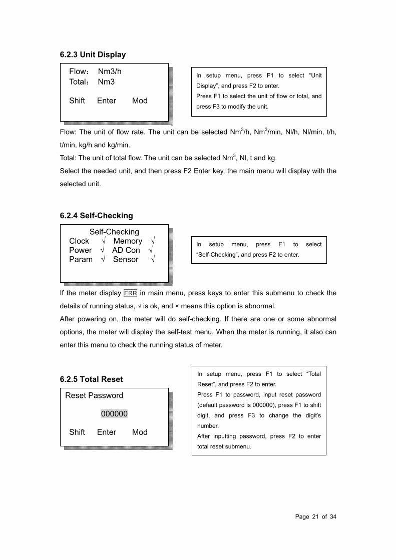
6.2.2 Setup Menu
--Setup menu-- 1.Unit Display 2.Self-Checking 3.Total Reset 4.Parameter Setup 5.Calibration 6.Password 7.Query
In main menu, press F2 to enter setup
menu.
In setup menu, press F1 and F2 at the
same time to enter main menu.
In main menu, press F2 to enter setup menu.
In setup menu, press F1 to select submenu,
and press F2 to enter submenu.
Page 21 of 34
6.2.3 Unit Display
Flow: The unit of flow rate. The unit can be selected Nm3/h, Nm3/min, Nl/h, Nl/min, t/h,
t/min, kg/h and kg/min.
Total: The unit of total flow. The unit can be selected Nm3, Nl, t and kg.
Select the needed unit, and then press F2 Enter key, the main menu will display with the
selected unit.
6.2.4 Self-Checking
If the meter display ERR in main menu, press keys to enter this submenu to check the
details of running status, √ is ok, and × means this option is abnormal.
After powering on, the meter will do self-checking. If there are one or some abnormal
options, the meter will display the self-test menu. When the meter is running, it also can
enter this menu to check the running status of meter.
6.2.5 Total Reset
Reset Password
000000 Shift Enter Mod
Self-Checking Clock √ Memory √ Power √ AD Con √ Param √ Sensor √
Flow: Nm3/h Total: Nm3
Shift Enter Mod
In setup menu, press F1 to select “Unit
Display”, and press F2 to enter.
Press F1 to select the unit of flow or total, and
press F3 to modify the unit.
In setup menu, press F1 to select
“Self-Checking”, and press F2 to enter.
In setup menu, press F1 to select “Total
Reset”, and press F2 to enter.
Press F1 to password, input reset password
(default password is 000000), press F1 to shift
digit, and press F3 to change the digit’s
number.
After inputting password, press F2 to enter
total reset submenu.

Page 22 of 34
6.2.6 Parameter Setup
Filter Coe 00 Shift Enter Mod
Equivalent ID
0100.000 mm Shift Enter Mod
Language/语言
English Shift Enter Mod
Password Setup
000000 Shift Enter Mod
Running Time Reset
00000000 min Reset Enter Reset
Total Reset
0000000.0000 Reset Enter Reset
In order to prevent error operation, press F1
and F3 keys at the same time to do total reset.
After finishing total reset, the display shows
0000000.0000.
In this submenu, press F2 key to enter running
time reset.
The unit of running time is minute.
The largest time is with 8 digits, and the reset
operation is as the same as total reset.
After resetting, press F2 key to return main
menu.
In setup menu, press F1 to select “Parameter
Setup”, and press F2 to enter.
Input reset password (default password is
000000), press F1 to shift digit, and press F3
to change the digit’s number.
After inputting password, press F2 to finish
password setup and enter language setup.
Press F3 to select the display language, and
then press F2 to finish selection and enter
Equivalent ID.
Equivalent ID is used to input the inner
diameter of pipe. For rectangular tube, it needs
to input a equivalent inner diameter. The unit is
mm.
The range is 0000.000~9999.999.
Press F2 to enter filter coefficient.
Filter coefficient. If the flow has a big
fluctuation, increase this value to get a stable
reading.
The range is 0~32, 0 means no filter.
Press F2 to enter low flow cutoff.

Page 23 of 34
Density SC
1.0000 Kg/m3 Shift Enter Mod
HART Address: 00 Protect: Close Shift Enter Mod
Address: 001 Baud: 9600 Parity: None Shift Enter Mod
Full Scale Flow 0000000.000 Shift Enter Mod
Medium: 00 Air Conversion Coe: 01.0000 Shift Enter Mod
Low Flow Cutoff
000000.000 Shift Enter Mod
Low flow cutoff. Cut off the low flow according
to the actual situation, and the unit is the same
as flow rate.
The range is 0000.0000~9999.9999.
Press F2 to enter Density in Standard
Condition.
The conversion coefficient in meter is
reference value, if necessary, modify this
value.
The meter contain the conversion coefficient of
59 gases, if the medium is mixed gas, it needs
to calculate the coefficient.
The density and conversion coefficient of
common gas are shown in appendix 3.
Press F2 to enter Full scale flow.
Full scale flow. Corresponding to 4-20mA
output, and the unit is the same as flow rate.
The range is 0000.0000~9999.9999.
Press F2 to enter RS485 communication.
RS485 communication setup.
The meter’s address range: 0~255. Baud rate
can be selected 1200, 2400, 4800 and 9600.
Parity check can be selected none, odd and
even.
Press F2 to enter HART setup.
HART communication setup.
The HART address range: 00~15. Protect is
“Close”, the HART operator can write data;
Protect is “Open”, the HART operator can’t
write data.
Press F2 to enter frequency output.
Density in Standard Condition.
(20,101.325KPa).
That is used for flow rate display.
Page 24 of 34
6.2.7 Calibration
The parameters in this submenu are very important. In order to prevent unauthorized
operation or wrong operation, it needs to input password before entering this submenu.
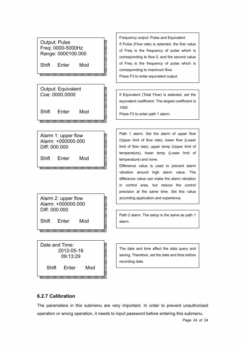
Date and Time: 2012-05-16
09:13:29
Shift Enter Mod
Alarm 2: upper flow Alarm: +000000.000 Diff: 000.000 Shift Enter Mod
Alarm 1: upper flow Alarm: +000000.000 Diff: 000.000 Shift Enter Mod
Output: Equivalent Coe: 0000.0000 Shift Enter Mod
Output: Pulse Freq: 0000-5000Hz Range: 0000100.000 Shift Enter Mod
Frequency output: Pulse and Equivalent.
If Pulse (Flow rate) is selected, the first value
of Freq is the frequency of pulse which is
corresponding to flow 0, and the second value
of Freq is the frequency of pulse which is
corresponding to maximum flow.
Press F3 to enter equivalent output.
If Equivalent (Total Flow) is selected, set the
equivalent coefficient. The largest coefficient is
1000.
Press F2 to enter path 1 alarm.
Path 1 alarm. Set the alarm of upper flow
(Upper limit of flow rate), lower flow (Lower
limit of flow rate), upper temp (Upper limit of
temperature), lower temp (Lower limit of
temperature) and none.
Difference value is used to prevent alarm
vibration around high alarm value. The
difference value can make the alarm vibration
in control area, but reduce the control
precision at the same time. Set this value
according application and experience.
Path 2 alarm. The setup is the same as path 1
alarm.
The date and time affect the data query and
saving. Therefore, set the date and time before
recording data.

Page 25 of 34
Flow correct: section 0 Flow: 0000000.000 Coe: 000000.0000 Shift Enter Mod
Velocity table: 01 Volt: 00/0000 V Vel: 000.000 Nm/s Shift Enter Mod
R Value (0): 1000.000Ω Shift Enter Mod
Zero Volt: Input 0.6500V Please confirm the flow is 0 Shift Enter Mod
Zero Volt: Measure 0.6500V Please confirm the flow is 0 Shift Enter Mod
Password
000000 Shift Enter Mod
In setup menu, press F1 to select “Calibration”,
and press F2 to enter.
Input the right password to enter calibration
submenu.
Press F2 to enter zero voltage value.
Zero voltage value is used to set the voltage
value while the flow rate is 0.
Before calibration, confirm the flow in pipe is
zero, and waiting for more than 30s to steady
the flow. Press F1 and F3 keys at the same
time until the meter displays success.
This value is can be input manually. Press F3
to select “Input”, input this value manually, and
then press F2 to enter R value.
Note: Don’t input zero voltage value when the
meter is running.
The resistance value is used to input the
resistance value of temperature sensor.
Press F2 to enter velocity table.
Velocity table. Set the voltage and velocity in
more than 40 sections.
After calibration, Input the voltage and velocity
from small section to large section. (The
velocity is zero in section 00).
Press F2 to enter flow correction.
Note: The meter calculates the flow by velocity
table. Please don’t modify the data in the table.
Flow correction. It can correct the flow in 5
sections.
Page 26 of 34
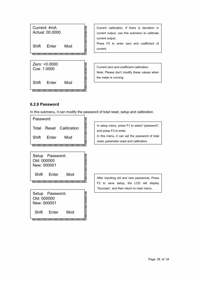
6.2.8 Password
In this submenu, it can modify the password of total reset, setup and calibration.
Setup Password: Old: 000000 New: 000001 Shift Enter Mod
Setup Password: Old: 000000 New: 000001 Shift Enter Mod
Password Total Reset Calibration Shift Enter Mod
Zero: +0.0000 Coe: 1.0000 Shift Enter Mod
Current: 4mA Actual: 00.0000 Shift Enter Mod
Current calibration. If there is deviation in
current output, use this submenu to calibrate
current output.
Press F2 to enter zero and coefficient of
current.
Current zero and coefficient calibration.
Note: Please don’t modify these values when
the meter is running.
In setup menu, press F1 to select “password”,
and press F2 to enter.
In this menu, it can set the password of total
reset, parameter reset and calibration.
After inputting old and new passwords, Press
F2 to save setup, the LCD will display
“Success”, and then return to main menu.
Page 27 of 34
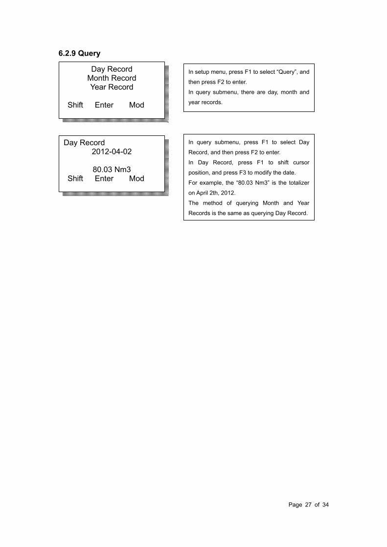
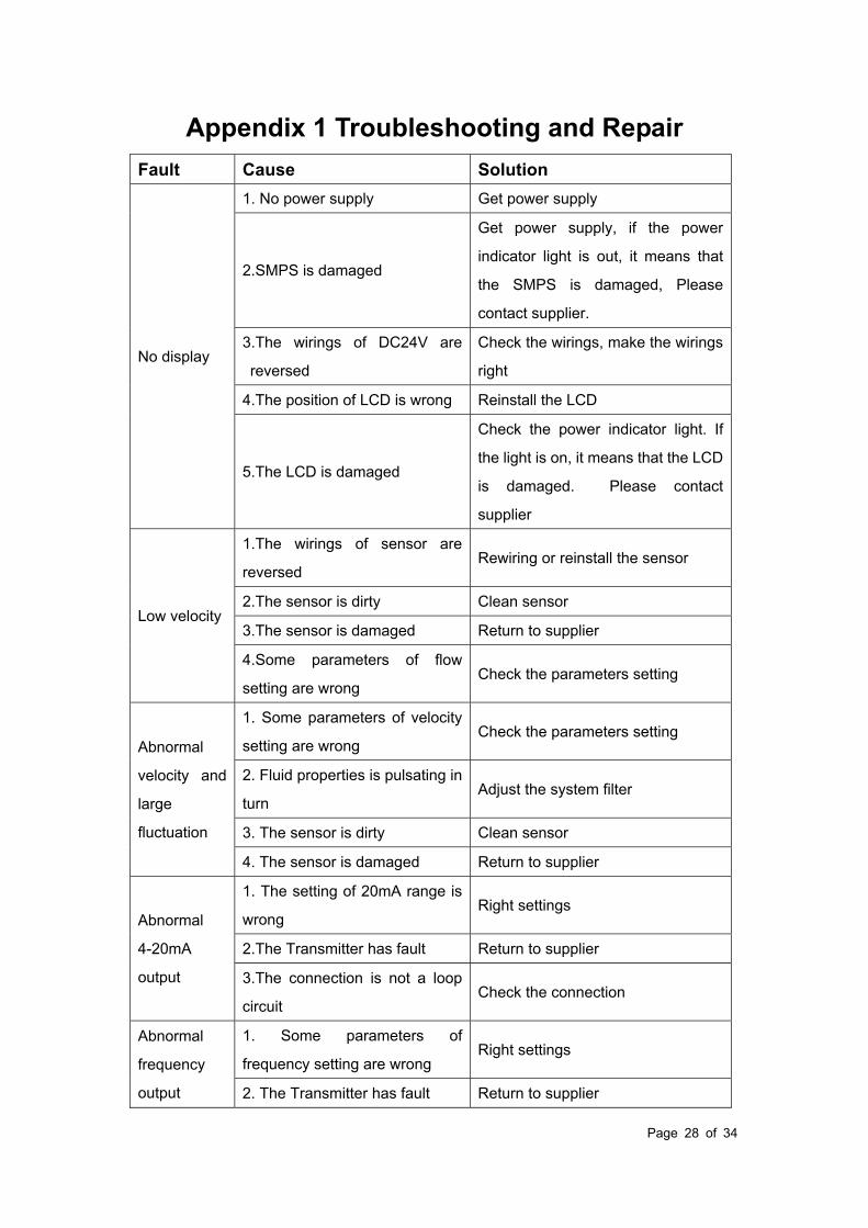
6.2.9 Query
Day Record 2012-04-02
80.03 Nm3
Shift Enter Mod
Day Record Month Record Year Record
Shift Enter Mod
In setup menu, press F1 to select “Query”, and
then press F2 to enter.
In query submenu, there are day, month and
year records.
In query submenu, press F1 to select Day
Record, and then press F2 to enter.
In Day Record, press F1 to shift cursor
position, and press F3 to modify the date.
For example, the “80.03 Nm3” is the totalizer
on April 2th, 2012.
The method of querying Month and Year
Records is the same as querying Day Record.
Page 28 of 34
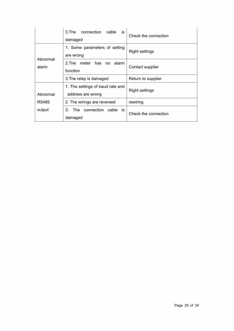
Appendix 1 Troubleshooting and Repair
Fault Cause Solution
No display
1. No power supply Get power supply
2.SMPS is damaged
Get power supply, if the power
indicator light is out, it means that
the SMPS is damaged, Please
contact supplier.
3.The wirings of DC24V are
reversed
Check the wirings, make the wirings
right
4.The position of LCD is wrong Reinstall the LCD
5.The LCD is damaged
Check the power indicator light. If
the light is on, it means that the LCD
is damaged. Please contact
supplier
Low velocity
1.The wirings of sensor are
reversed Rewiring or reinstall the sensor
2.The sensor is dirty Clean sensor
3.The sensor is damaged Return to supplier
4.Some parameters of flow
setting are wrong Check the parameters setting
Abnormal
velocity and
large
fluctuation
1. Some parameters of velocity
setting are wrong Check the parameters setting
2. Fluid properties is pulsating in
turn Adjust the system filter
3. The sensor is dirty Clean sensor
4. The sensor is damaged Return to supplier
Abnormal
4-20mA
output
1. The setting of 20mA range is
wrong Right settings
2.The Transmitter has fault Return to supplier
3.The connection is not a loop
circuit Check the connection
Abnormal
frequency
output
1. Some parameters of
frequency setting are wrong Right settings
2. The Transmitter has fault Return to supplier
Page 29 of 34
3.The connection cable is
damaged Check the connection
Abnormal
alarm
1. Some parameters of setting
are wrong Right settings
2.The meter has no alarm
function Contact supplier
3.The relay is damaged Return to supplier
Abnormal
RS485
output
1. The settings of baud rate and
address are wrong Right settings
2. The wirings are reversed rewiring
3. The connection cable is
damaged Check the connection

Page 30 of 34
Appendix 2 The Density and Conversion
Coefficient of Common Gas
According to different gas on site, the calibration in lab translates the flow rate of actual
gas on site into flow rate of air, and then begins to calibrate the flow rate at present.
Therefore, when using the meter on site, the meter displays mass flow or volume flow of
actual gas.
When translating the flow rate of gas into flow rate of air, there is a conversion coefficient
table of different gas.
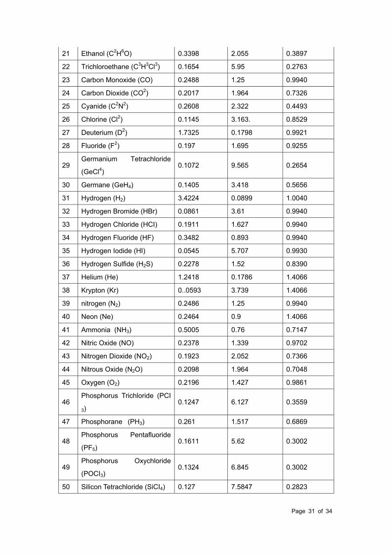
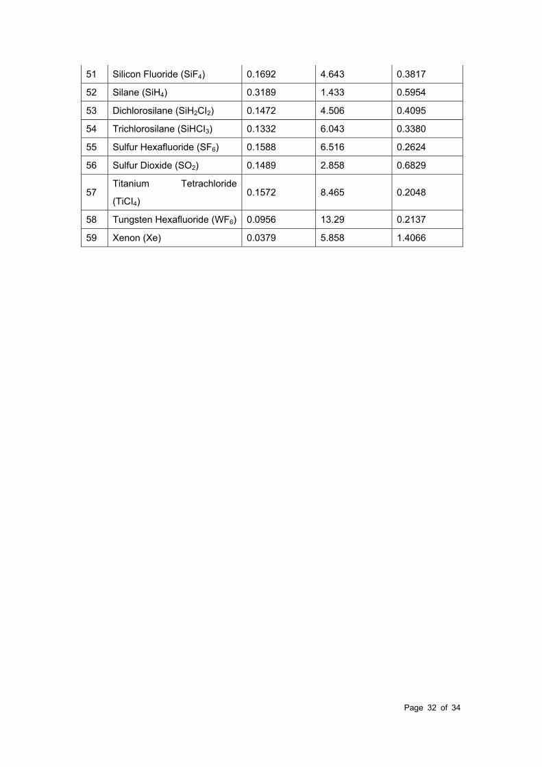
Table 1 The Density and Conversion Coefficient of Common Gas
Gas
Specific heat
(Kal/g*)
Density
(g/l, 0)
Conversion
Coefficient
0 Air 0.24 1.2048 1.0000
1 Argon (Ar) 0.125 1.6605 1.4066
2 Arsine (AsH3) 0.1168 3.478 0.6690
3 Boron Tribromide (BBr3) 0.0647 11.18 0.3758
4 Boron Trichloride (BCl3) 0.1217 5.227 0.4274
5 Boron Trifluoride ( BF3) 0.1779 3.025 0.5050
6 Borane (B2H6) 0.502 1.235 0.4384
7 Carbon Tetrachloride (CCl4) 0.1297 6.86 0.3052
8 Carbon Tetrafluoride (CF4) 0.1659 3.9636 0.4255
9 Methane (CH4) 0.5318 0.715 0.7147
10 Acetylene (C2H2) 0.4049 1.162 0.5775
11 Ethylene (C2H4) 0.3658 1.251 0.5944
12 Ethane (C2H6) 0.4241 1.342 0.4781
13 Allylene (C3H4) 0.3633 1.787 0.4185
14 Propylene (C3H6) 0.3659 1.877 0.3956
15 Propane (C3H8) 0.399 1.967 0.3459
16 Butyne (C4H6) 0.3515 2.413 0.3201
17 Butene (C4H8) 0.3723 2.503 0.2923
18 Butane (C4H10) 0.413 2.593 0.2535
19 Pentane (C5H12) 0.3916 3.219 0.2157
20 Carbinol (CH3OH) 0.3277 1.43 0.5805
Page 31 of 34
21 Ethanol (C2H6O) 0.3398 2.055 0.3897
22 Trichloroethane (C3H3Cl3) 0.1654 5.95 0.2763
23 Carbon Monoxide (CO) 0.2488 1.25 0.9940
24 Carbon Dioxide (CO2) 0.2017 1.964 0.7326
25 Cyanide (C2N2) 0.2608 2.322 0.4493
26 Chlorine (Cl2) 0.1145 3.163. 0.8529
27 Deuterium (D2) 1.7325 0.1798 0.9921
28 Fluoride (F2) 0.197 1.695 0.9255
29 Germanium Tetrachloride
(GeCl4) 0.1072 9.565 0.2654
30 Germane (GeH4) 0.1405 3.418 0.5656
31 Hydrogen (H2) 3.4224 0.0899 1.0040
32 Hydrogen Bromide (HBr) 0.0861 3.61 0.9940
33 Hydrogen Chloride (HCI) 0.1911 1.627 0.9940
34 Hydrogen Fluoride (HF) 0.3482 0.893 0.9940
35 Hydrogen Iodide (HI) 0.0545 5.707 0.9930
36 Hydrogen Sulfide (H2S) 0.2278 1.52 0.8390
37 Helium (He) 1.2418 0.1786 1.4066
38 Krypton (Kr) 0..0593 3.739 1.4066
39 nitrogen (N2) 0.2486 1.25 0.9940
40 Neon (Ne) 0.2464 0.9 1.4066
41 Ammonia (NH3) 0.5005 0.76 0.7147
42 Nitric Oxide (NO) 0.2378 1.339 0.9702
43 Nitrogen Dioxide (NO2) 0.1923 2.052 0.7366
44 Nitrous Oxide (N2O) 0.2098 1.964 0.7048
45 Oxygen (O2) 0.2196 1.427 0.9861
46 Phosphorus Trichloride (PCI
3) 0.1247 6.127 0.3559
47 Phosphorane (PH3) 0.261 1.517 0.6869
48 Phosphorus Pentafluoride
(PF5) 0.1611 5.62 0.3002
49 Phosphorus Oxychloride
(POCI3) 0.1324 6.845 0.3002
50 Silicon Tetrachloride (SiCI4) 0.127 7.5847 0.2823
Page 32 of 34
51 Silicon Fluoride (SiF4) 0.1692 4.643 0.3817
52 Silane (SiH4) 0.3189 1.433 0.5954
53 Dichlorosilane (SiH2CI2) 0.1472 4.506 0.4095
54 Trichlorosilane (SiHCI3) 0.1332 6.043 0.3380
55 Sulfur Hexafluoride (SF6) 0.1588 6.516 0.2624
56 Sulfur Dioxide (SO2) 0.1489 2.858 0.6829
57 Titanium Tetrachloride
(TiCI4) 0.1572 8.465 0.2048
58 Tungsten Hexafluoride (WF6) 0.0956 13.29 0.2137
59 Xenon (Xe) 0.0379 5.858 1.4066

Page 33 of 34
Appendix 3 Upper Range Value of Common Gas
(Unit: Nm3/h. The follow table can be extended)
Nominal
Diameter
(mm)
Air Nitrogen(N2) Oxygen(O2) Hydrogen(H2)
15 65 65 32 10
25 175 175 89 28
32 290 290 144 45
40 450 450 226 70
50 700 700 352 110
65 1200 1200 600 185
80 1800 1800 900 280
100 2800 2800 1420 470
125 4400 4400 2210 700
150 6300 6300 3200 940
200 10000 10000 5650 1880
250 17000 17000 8830 2820
300 25000 25000 12720 4060
400 45000 45000 22608 7200
500 70000 70000 35325 11280
600 100000 100000 50638 16300
700 135000 135000 69240 22100
800 180000 180000 90432 29000
900 220000 220000 114500 77807
1000 280000 280000 141300 81120
1200 400000 400000 203480 91972
1500 600000 600000 318000 101520
2000 700000 700000 565200 180480
The flow rate in standard condition: The flow rate is in the condition of 20 temperature
and 101.325kPa pressure.
The unit of flow rate is optional: Nm3/h, Nm3/min, L/h, L/min, t/h, t/min, kg/h or kg/min.
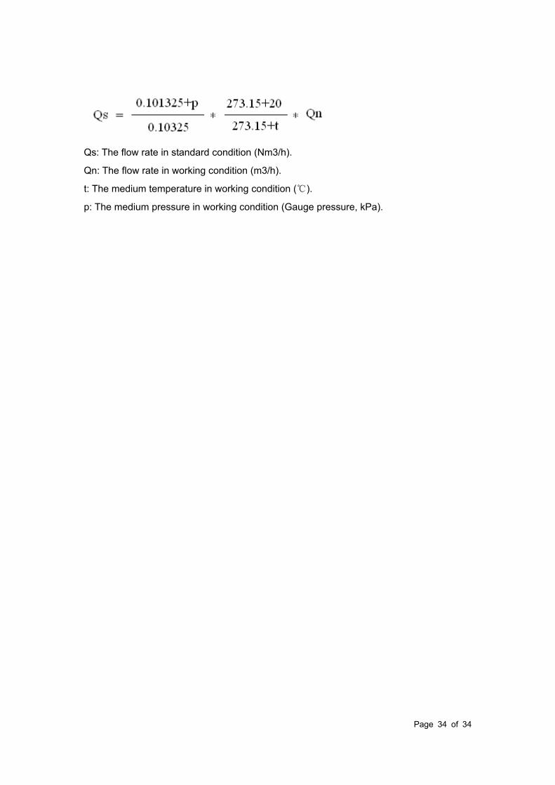
The reduction formula of flow rate in working condition and flow rate in standard condition:
Page 34 of 34
Qs: The flow rate in standard condition (Nm3/h).
Qn: The flow rate in working condition (m3/h).
t: The medium temperature in working condition ().
p: The medium pressure in working condition (Gauge pressure, kPa).