thermal deformations and stresses...lecture title: thermal deformations and stresses lecture notes...
TRANSCRIPT
Lecture Title: Thermal Deformations and stresses Lecture Notes on Strength of Materials (2014-2015)
University Of Technology Mechanical Engineering Department
Page 1 of 8 Dr. Hassan Mohammed, Asst. Prof. Dr. Mohsin Noori
Asst. Lecturer Rasha Mohammed
THERMAL DEFORMATIONS AND STRESSES
Introduction
It is well known that changes in temperature cause dimensional changes in a
body: An increase in temperature results in expansion, whereas a temperature
decrease produces contraction. This deformation is isotropic (the same in every
direction) and proportional to the temperature change. The strain caused by
temperature change (°C) is denoted by 𝛼 and is called the coefficient of thermal
expansion. Thermal strain caused by a uniform increase in temperature ΔT is
휀𝑡ℎ = 𝛼∆𝑇
and
𝛿𝑡ℎ = 𝛼(∆𝑇)𝐿
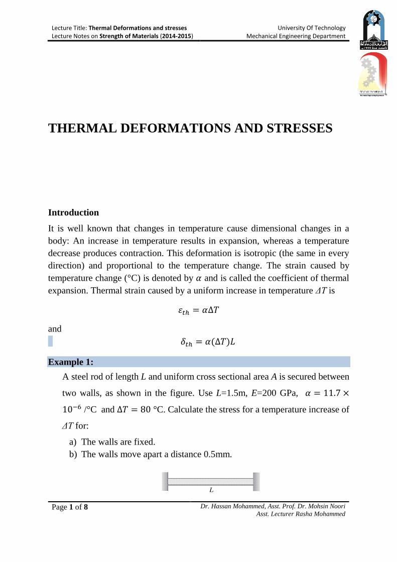
Example 1:
A steel rod of length L and uniform cross sectional area A is secured between
two walls, as shown in the figure. Use L=1.5m, E=200 GPa, 𝛼 = 11.7 ×
10−6 /°C and ∆𝑇 = 80 °C. Calculate the stress for a temperature increase of
ΔT for:
a) The walls are fixed.
b) The walls move apart a distance 0.5mm.
Lecture Title: Thermal Deformations and stresses Lecture Notes on Strength of Materials (2014-2015)
University Of Technology Mechanical Engineering Department
Page 2 of 8 Dr. Hassan Mohammed, Asst. Prof. Dr. Mohsin Noori
Asst. Lecturer Rasha Mohammed
Solution:
a) 𝛿𝑡ℎ − 𝛿𝑅 = 0
𝛼(∆𝑇)𝐿 −𝑅𝐿
𝐴𝐸= 0
R=A E α (ΔT)
𝜎 =𝑅
𝐴= 𝐸𝛼(∆𝑇)
= 200 × 109 × 11.7 × 10−6 × 80 = 187.2 MPa (Answer)
b) 𝛿𝑡ℎ − 𝛿𝑅 = 𝛿𝑤
𝛼(∆𝑇)𝐿 −𝑅𝐿
𝐴𝐸= 𝛿𝑤
R=AE (α ΔT - 𝛿𝑤
𝐿)
The compressive stress is then,
𝜎 =𝑅
𝐴= 𝐸 (𝛼∆𝑇 −
𝛿𝑤
𝐿)
= 200 × 109 (11.7 × 10−6 × 80 −0.5×10⁻³
1.5) = 120.52 MPa (Answer)
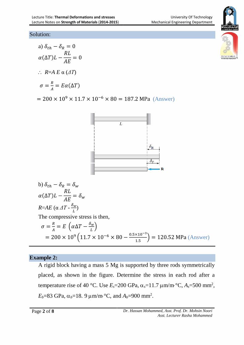
Example 2:
A rigid block having a mass 5 Mg is supported by three rods symmetrically
placed, as shown in the figure. Determine the stress in each rod after a
temperature rise of 40 °C. Use Es=200 GPa, s=11.7 m/m°C, As=500 mm2,
Eb=83 GPa, b=18. 9 m/m°C, and Ab=900 mm2.
Lecture Title: Thermal Deformations and stresses Lecture Notes on Strength of Materials (2014-2015)
University Of Technology Mechanical Engineering Department
Page 3 of 8 Dr. Hassan Mohammed, Asst. Prof. Dr. Mohsin Noori
Asst. Lecturer Rasha Mohammed
Solution:
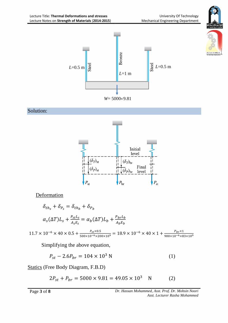
Deformation
𝛿𝑡ℎ𝑠+ 𝛿𝑃𝑠
= 𝛿𝑡ℎ𝑏+ 𝛿𝑃𝑏
𝛼𝑠(∆𝑇)𝐿𝑠 +𝑃𝑠𝑡𝐿𝑠
𝐴𝑠𝐸𝑠= 𝛼𝑏(∆𝑇)𝐿𝑏 +
𝑃𝑏𝑟𝐿𝑏
𝐴𝑏𝐸𝑏
11.7 × 10−6 × 40 × 0.5 +𝑃𝑠𝑡×0.5
500×10−6×200×109 = 18.9 × 10−6 × 40 × 1 +𝑃𝑏𝑟×1
900×10−6×83×109
Simplifying the above equation,
𝑃𝑠𝑡 − 2.6𝑃𝑏𝑟 = 104 × 103 N (1)
Statics (Free Body Diagram, F.B.D)
2𝑃𝑠𝑡 + 𝑃𝑏𝑟 = 5000 × 9.81 = 49.05 × 10³ N (2)
L=0.5 m L=0.5 m
L=1 m
W= 50009.81
Lecture Title: Thermal Deformations and stresses Lecture Notes on Strength of Materials (2014-2015)
University Of Technology Mechanical Engineering Department
Page 4 of 8 Dr. Hassan Mohammed, Asst. Prof. Dr. Mohsin Noori
Asst. Lecturer Rasha Mohammed
Solving equation (1) and (2),
𝑃𝑠𝑡 = 37.0 kN and 𝑃𝑏𝑟 = −25 kN (compression)
Stresses
𝜎 =𝐹
𝐴, hence 𝜎𝑠 =
𝑃𝑠𝑡
𝐴𝑠=
37×103
500×10−6= 74 MPa (Answer)
𝜎𝑏 =𝑃𝑠𝑡
𝐴𝑏=
25∗103
900∗10−6= 27.8 MPa (Answer)
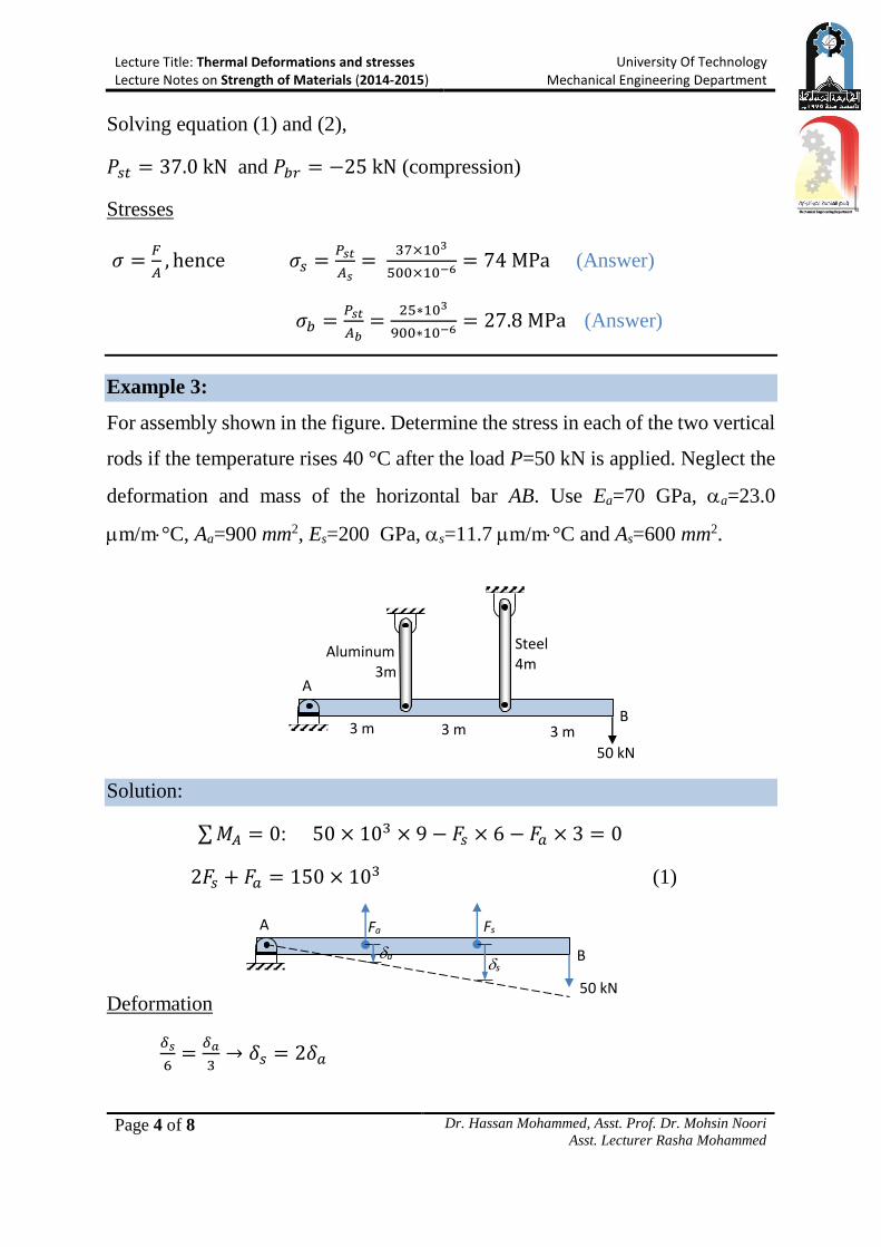
Example 3:
For assembly shown in the figure. Determine the stress in each of the two vertical
rods if the temperature rises 40 °C after the load P=50 kN is applied. Neglect the
deformation and mass of the horizontal bar AB. Use Ea=70 GPa, a=23.0
m/m°C, Aa=900 mm2, Es=200 GPa, s=11.7 m/m°C and As=600 mm2.
Solution:
∑ 𝑀𝐴 = 0: 50 × 103 × 9 − 𝐹𝑠 × 6 − 𝐹𝑎 × 3 = 0
2𝐹𝑠 + 𝐹𝑎 = 150 × 103 (1)
Deformation
𝛿𝑠
6=
𝛿𝑎
3→ 𝛿𝑠 = 2𝛿𝑎
Aluminum 3m
A
B 3 m 3 m 3 m
50 kN
Steel 4m
A
B
50 kN
Fs Fa
a s
Lecture Title: Thermal Deformations and stresses Lecture Notes on Strength of Materials (2014-2015)
University Of Technology Mechanical Engineering Department
Page 5 of 8 Dr. Hassan Mohammed, Asst. Prof. Dr. Mohsin Noori
Asst. Lecturer Rasha Mohammed
𝛼𝑠(∆𝑇)𝐿𝑠 +𝐹𝑠𝐿𝑠
𝐴𝑠𝐸𝑠= 2 (𝛼𝑎(∆𝑇)𝐿𝑎 +
𝐹𝑎𝐿𝑎
𝐴𝑎𝐸𝑎)
11.7 × 10−6 × 40 × 4 +𝐹𝑠×4
600×10−6×200×109=
2 (23 × 10−6 × 40 × 3 +𝐹𝑎×3
900×10−6×70×109)
𝐹𝑠 − 2.857𝐹𝑎 = 109.44 kN (2)
Solve (1) and (2) for 𝐹𝑠 and 𝐹𝑎,
𝐹𝑠 = 80.4 kN and 𝐹𝑎 = −10.17 kN
Stresses
𝜎𝑠 =𝐹𝑠
𝐴𝑠 =
80.4×10³
600×10−6= 11.3 𝑀𝑃𝑎 (Answer)
𝜎𝑎 =𝐹𝑎
𝐴𝑎 =
10.17×10³
900×10−6= 134 MPa (Answer)
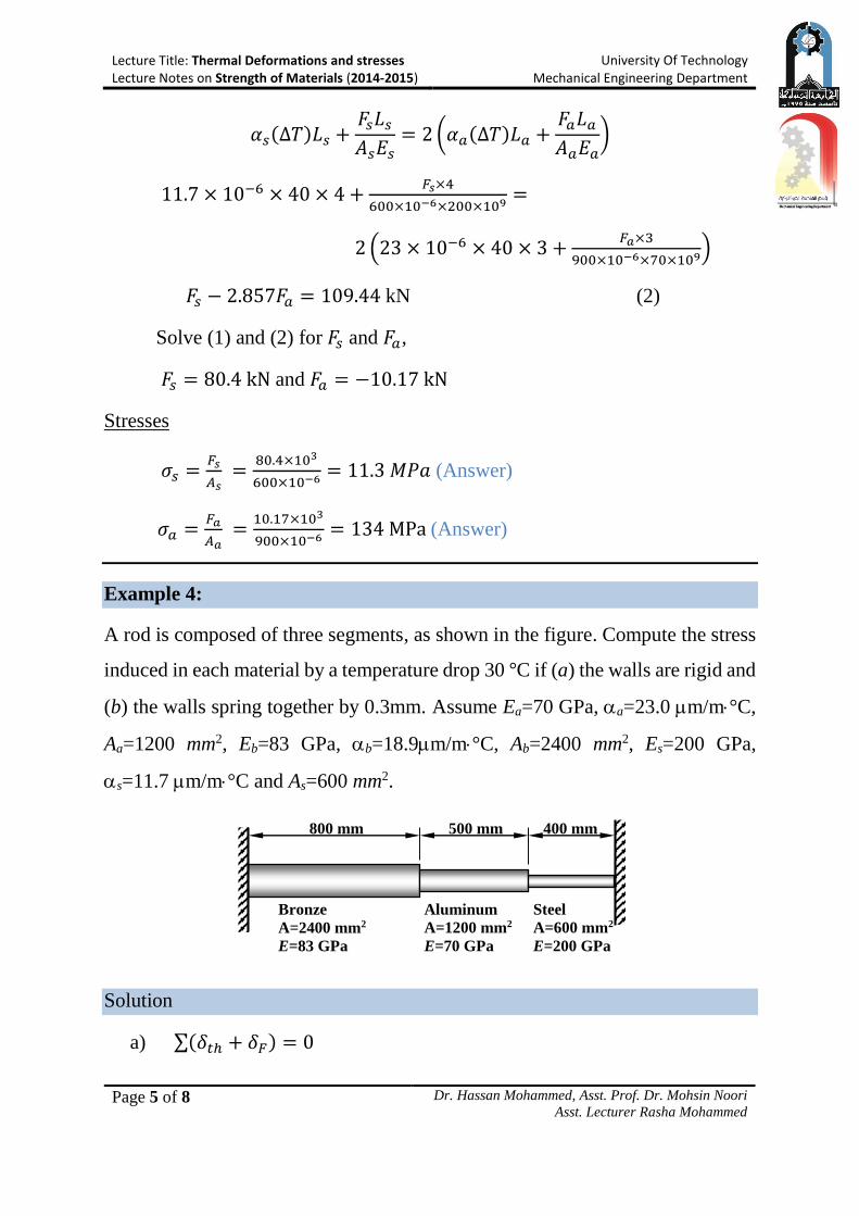
Example 4:
A rod is composed of three segments, as shown in the figure. Compute the stress
induced in each material by a temperature drop 30 °C if (a) the walls are rigid and
(b) the walls spring together by 0.3mm. Assume Ea=70 GPa, a=23.0 m/m°C,
Aa=1200 mm2, Eb=83 GPa, b=18.9m/m°C, Ab=2400 mm2, Es=200 GPa,
s=11.7 m/m°C and As=600 mm2.
Solution
a) ∑(𝛿𝑡ℎ + 𝛿𝐹) = 0
800 mm 500 mm 400 mm
Bronze
A=2400 mm2
E=83 GPa
Aluminum
A=1200 mm2
E=70 GPa
Steel
A=600 mm2
E=200 GPa
Lecture Title: Thermal Deformations and stresses Lecture Notes on Strength of Materials (2014-2015)
University Of Technology Mechanical Engineering Department
Page 6 of 8 Dr. Hassan Mohammed, Asst. Prof. Dr. Mohsin Noori
Asst. Lecturer Rasha Mohammed
18.9 × 10−6 × 30 × 0.8 −𝐹 ∗ 0.8
2400 × 10−6 × 83 × 109+ 23 × 10−6 × 30 × 0.5
−𝐹 × 0.5
1200 × 10−6 × 70 × 109+ 11.7 × 10−6 × 30 × 0.4
−𝐹 × 0.4
600 × 10−6 × 200 × 109= 0
F=70.592 kN
Stresses
𝜎𝑠 =𝐹𝑠
𝐴𝑠 =
70.592×10³
600×10−6= 117.65 MPa (Answer)
𝜎𝑎 =𝐹𝑎
𝐴𝑎=
70.592×10³
1200×10−6= 58.82 MPa (Answer)
𝜎𝑏 =𝐹𝑏
𝐴𝑏=
70.592×10³
2400×10−6= 29.41 MPa (Answer)
b) ∑(𝛿𝑡ℎ + 𝛿𝐹) = 0.3 × 10⁻³
18.9 × 10−6 × 30 × 0.8 −𝐹 ∗ 0.8
2400 × 10−6 × 83 × 109+ 23 × 10−6 × 30 × 0.5
−𝐹 × 0.5
1200 × 10−6 × 70 × 109+ 11.7 × 10−6 × 30 × 0.4
−𝐹 × 0.4
600 × 10−6 × 200 × 109= 0.3 ∗ 10−3
F=49.15KN
Stresses
𝜎𝑠 =𝐹𝑠
𝐴𝑠 =
49.15×10³
600×10−6= 81.91 MPa (Answer)
𝜎𝑎 =𝐹𝑎
𝐴𝑎=
49.15×10³
1200×10−6= 40.95 MPa (Answer)
𝜎𝑏 =𝐹𝑏
𝐴𝑏=
49.15×10³
2400×10−6= 20.47 MPa (Answer)
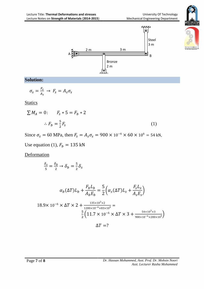
Example 5:
A rigid horizontal bar of negligible mass is connected to two rods as shown in the
figure. If the system is initially stress-free; determine the temperature change that
will cause a tensile stress of 60 MPa in the steel rod. Assume Es=200 GPa,
s=11.7 m/m°C and As=900 mm2, Eb=83 GPa, b=18.9m/m°C, Ab=1200 mm2.
Lecture Title: Thermal Deformations and stresses Lecture Notes on Strength of Materials (2014-2015)
University Of Technology Mechanical Engineering Department
Page 7 of 8 Dr. Hassan Mohammed, Asst. Prof. Dr. Mohsin Noori
Asst. Lecturer Rasha Mohammed
Solution:
𝜎𝑠 =𝐹𝑠
𝐴𝑠 → 𝐹𝑠 = 𝐴𝑠𝜎𝑠
Statics
∑ 𝑀𝐴 = 0: 𝐹𝑠 ∗ 5 = 𝐹𝑏 ∗ 2
∴ 𝐹𝑏 =5
2𝐹𝑠 (1)
Since 𝜎𝑠 = 60 MPa, then 𝐹𝑠 = 𝐴𝑠𝜎𝑠 = 900 × 10−6 × 60 × 106 = 54 kN,
Use equation (1), 𝐹𝑏 = 135 kN
Deformation
𝛿𝑠
5=
𝛿𝑏
2→ 𝛿𝑏 =
5
2𝛿𝑠
𝛼𝑏(∆𝑇)𝐿𝑏 +𝐹𝑏𝐿𝑏
𝐴𝑏𝐸𝑏=
5
2(𝛼𝑠(∆𝑇)𝐿𝑠 +
𝐹𝑠𝐿𝑠
𝐴𝑠𝐸𝑠)
18.9× 10⁻⁶ × ∆𝑇 × 2 +135×103×2
1200×10−6×83×109=
5
2(11.7 × 10⁻⁶ × ∆𝑇 × 3 +
54×103×3
900×10−6×200×109)
∆𝑇 =?
2 m 3 m
B
Bronze 2 m
Steel 3 m
A
Lecture Title: Thermal Deformations and stresses Lecture Notes on Strength of Materials (2014-2015)
University Of Technology Mechanical Engineering Department
Page 8 of 8 Dr. Hassan Mohammed, Asst. Prof. Dr. Mohsin Noori
Asst. Lecturer Rasha Mohammed
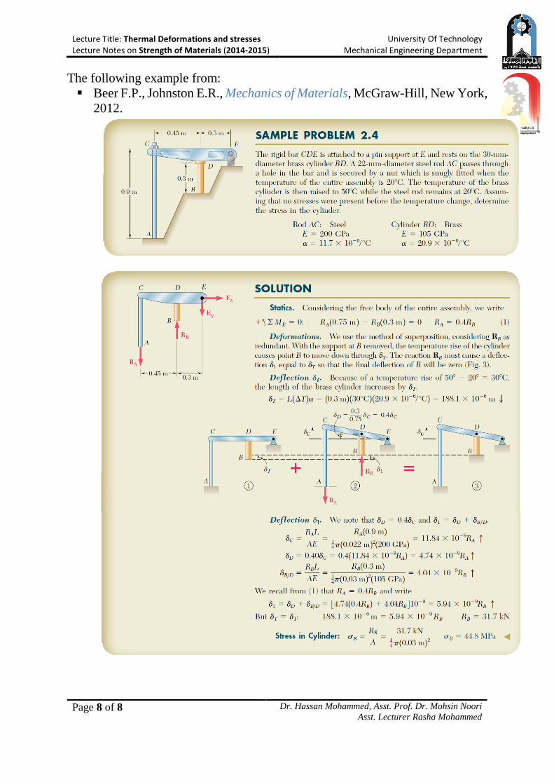
The following example from:
Beer F.P., Johnston E.R., Mechanics of Materials, McGraw-Hill, New York,
2012.
Lecture Title: Torsion of Thin-Walled Tubes Lecture Notes on Strength of Materials (2014-2015)
University Of Technology Mechanical Engineering Department
Page 1 of 8 Dr. Hassan Mohammed, Asst. Prof. Dr. Mohsin Noori
Asst. Lecturer Rasha Mohammed
TORSION OF THIN-WALLED TUBES
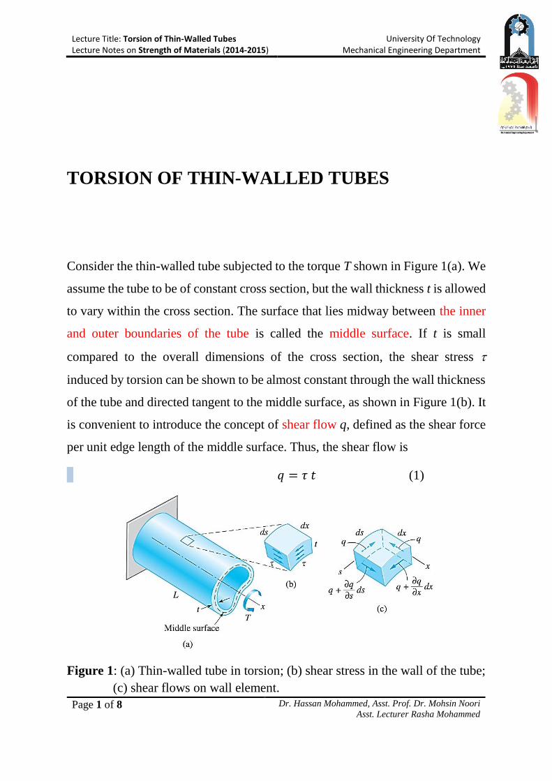
Consider the thin-walled tube subjected to the torque T shown in Figure 1(a). We
assume the tube to be of constant cross section, but the wall thickness t is allowed
to vary within the cross section. The surface that lies midway between the inner
and outer boundaries of the tube is called the middle surface. If t is small
compared to the overall dimensions of the cross section, the shear stress
induced by torsion can be shown to be almost constant through the wall thickness
of the tube and directed tangent to the middle surface, as shown in Figure 1(b). It
is convenient to introduce the concept of shear flow q, defined as the shear force
per unit edge length of the middle surface. Thus, the shear flow is
𝑞 = 𝜏 𝑡 (1)
Figure 1: (a) Thin-walled tube in torsion; (b) shear stress in the wall of the tube;
(c) shear flows on wall element.
Lecture Title: Torsion of Thin-Walled Tubes Lecture Notes on Strength of Materials (2014-2015)
University Of Technology Mechanical Engineering Department
Page 2 of 8 Dr. Hassan Mohammed, Asst. Prof. Dr. Mohsin Noori
Asst. Lecturer Rasha Mohammed
The shear flow is constant throughout the tube, as explained in what follows.
Considering the equilibrium of the element shown in Figure 1(c). In labeling the
shear flows, we assume that q varies in the longitudinal (x) as well as the
circumferential (s) directions. Thus, the terms (𝜕𝑞 𝜕𝑥⁄ ) 𝑑𝑥 and (𝜕𝑞 𝜕𝑠⁄ ) 𝑑𝑠
represent the changes in the shear flow over the distances dx and ds, respectively.
The force acting on each side of the element is equal to the shear flow multiplied
by the edge length, resulting in the equilibrium equations
∑ 𝐹𝑥 = 0: (𝑞 +𝜕𝑞
𝜕𝑠𝑑𝑠) 𝑑𝑥 − 𝑞 𝑑𝑥 = 0
∑ 𝐹𝑠 = 0: (𝑞 +𝜕𝑞
𝜕𝑥𝑑𝑥) 𝑑𝑠 − 𝑞 𝑑𝑠 = 0
which yield 𝜕𝑞
𝜕𝑠=
𝜕𝑞
𝜕𝑥= 0, thus proving that the shear flow is constant throughout
the tube.
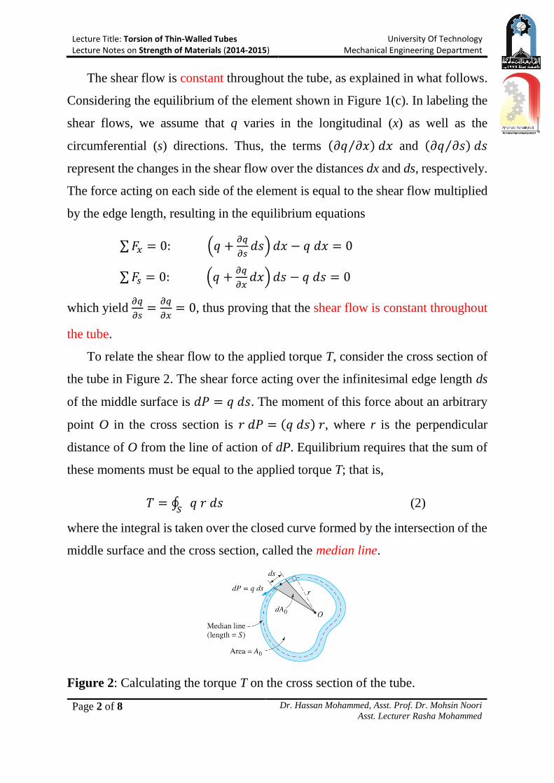
To relate the shear flow to the applied torque T, consider the cross section of
the tube in Figure 2. The shear force acting over the infinitesimal edge length ds
of the middle surface is 𝑑𝑃 = 𝑞 𝑑𝑠. The moment of this force about an arbitrary
point O in the cross section is 𝑟 𝑑𝑃 = (𝑞 𝑑𝑠) 𝑟, where r is the perpendicular
distance of O from the line of action of dP. Equilibrium requires that the sum of
these moments must be equal to the applied torque T; that is,
𝑇 = ∮ 𝑞 𝑟 𝑑𝑠𝑆
(2)
where the integral is taken over the closed curve formed by the intersection of the
middle surface and the cross section, called the median line.
Figure 2: Calculating the torque T on the cross section of the tube.
Lecture Title: Torsion of Thin-Walled Tubes Lecture Notes on Strength of Materials (2014-2015)
University Of Technology Mechanical Engineering Department
Page 3 of 8 Dr. Hassan Mohammed, Asst. Prof. Dr. Mohsin Noori
Asst. Lecturer Rasha Mohammed
Since q is constant, equation (2) can be written as 𝑇 = 𝑞 ∮ 𝑟 𝑑𝑠𝑆
. From
Figure 2 it can be seen that 𝑑𝐴0 =1
2𝑟 𝑑𝑠, where dA0 is the area of the shaded
triangle. Therefore, ∮ 𝑟 𝑑𝑠𝑆
= 2𝐴0, where A0 is the area of the cross section that
is enclosed by the median line. Consequently, equation (2) becomes
𝑇 = 2𝐴0 𝑞
from the shear flow is
𝑞 =𝑇
2𝐴0 (3)
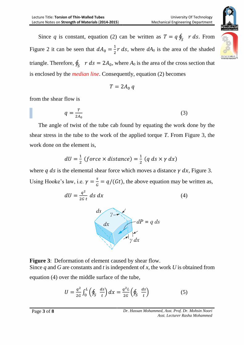
The angle of twist of the tube cab found by equating the work done by the
shear stress in the tube to the work of the applied torque T. From Figure 3, the
work done on the element is,
𝑑𝑈 =1
2 (𝑓𝑜𝑟𝑐𝑒 × 𝑑𝑖𝑠𝑡𝑎𝑛𝑐𝑒) =
1
2 (𝑞 𝑑𝑠 × 𝛾 𝑑𝑥)
where 𝑞 𝑑𝑠 is the elemental shear force which moves a distance 𝛾 𝑑𝑥, Figure 3.
Using Hooke’s law, i.e. 𝛾 =𝜏
𝐺= 𝑞/(𝐺𝑡), the above equation may be written as,
𝑑𝑈 =𝑞2
2𝐺 𝑡 𝑑𝑠 𝑑𝑥 (4)
Figure 3: Deformation of element caused by shear flow.
Since q and G are constants and t is independent of x, the work U is obtained from
equation (4) over the middle surface of the tube,
𝑈 =𝑞2
2𝐺∫ (∮
𝑑𝑠
𝑡𝑆) 𝑑𝑥
𝐿
0=
𝑞2𝐿
2𝐺(∮
𝑑𝑠
𝑡𝑆) (5)
Lecture Title: Torsion of Thin-Walled Tubes Lecture Notes on Strength of Materials (2014-2015)
University Of Technology Mechanical Engineering Department
Page 4 of 8 Dr. Hassan Mohammed, Asst. Prof. Dr. Mohsin Noori
Asst. Lecturer Rasha Mohammed
1 2
3 A2 A1
t1 t3 t2
E B A
C F D
Conservation of energy requires U to be equal to the work of the applied torque;
that is, 𝑈 = 𝑇 𝜃/2. Then, using equation (3), equation (5) will be,
(𝑇
2𝐴0)
2 𝐿
2𝐺(∮
𝑑𝑠
𝑡𝑆) =
1
2𝑇 𝜃
from which the angle of twist of the tube is
𝜃 =𝑇 𝐿
4 𝐺 𝐴02 (∮
𝑑𝑠
𝑡𝑆) (6)
If t is constant, we have ∮ (𝑑𝑠 𝑡⁄ )𝑆
= 𝑆 𝑡⁄ , where S is the length of the median
line. Therefore, equation (6) becomes
𝜃 =𝑇 𝐿 𝑆
4 𝐺 𝐴02 𝑡
= 𝜏 𝐿 𝑆
2 𝐴0 𝐺 (7)
For closed sections which have constant thickness over specified lengths but
varying from one part of the perimeter to another:
𝜃 =𝑇 𝐿
4 𝐺 𝐴02 (
𝑆1
𝑡1+
𝑆2
𝑡2+
𝑆3
𝑡3+ ⋯ etc. ) (8)
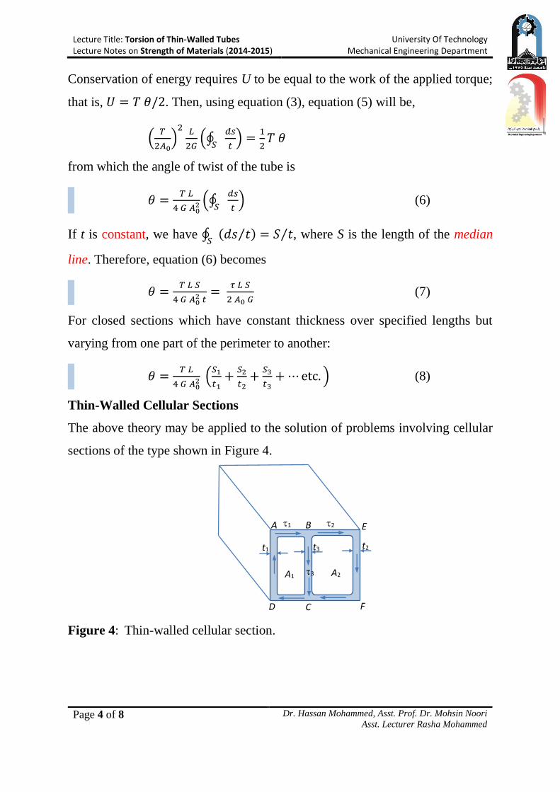
Thin-Walled Cellular Sections
The above theory may be applied to the solution of problems involving cellular
sections of the type shown in Figure 4.
Figure 4: Thin-walled cellular section.
Lecture Title: Torsion of Thin-Walled Tubes Lecture Notes on Strength of Materials (2014-2015)
University Of Technology Mechanical Engineering Department
Page 5 of 8 Dr. Hassan Mohammed, Asst. Prof. Dr. Mohsin Noori
Asst. Lecturer Rasha Mohammed
Assume the length CDAB is of constant thickness tl and subjected therefore
to a constant shear stress 1. Similarly, BEFC is of thickness t2 and stress 2 with
BC of thickness t3 and stress 3.
Considering the equilibrium of complementary shear stresses on a
longitudinal section at B, it follows that
𝑞1 = 𝑞2 + 𝑞3
or
𝜏1𝑡1 = 𝜏2𝑡2 + 𝜏3𝑡3 (9)
The total torque for the section is then found as the sum of the torques on the
two cells by application of equation (3) to the two cells and adding the result,
𝑇 = 2𝑞1𝐴1 + 2𝑞2𝐴2 = 2(𝜏1𝑡1𝐴1 + 𝜏2𝑡2𝐴2) (10)
The angle of twist will be common to both cells, i.e.,
𝜃 =𝐿
2𝐺(
𝜏1𝑆1+𝜏3𝑆3
𝐴1) =
𝐿
2𝐺(
𝜏2𝑆2−𝜏3𝑆3
𝐴2) (11)
where 𝑆1, 𝑆2 and 𝑆3 are the median line perimeters CDAB, BEFC and BC
respectively.
Note: The negative sign appears in the final term because the shear flow along
BC for this cell opposes that in the remainder of the perimeter.
Lecture Title: Torsion of Thin-Walled Tubes Lecture Notes on Strength of Materials (2014-2015)
University Of Technology Mechanical Engineering Department
Page 6 of 8 Dr. Hassan Mohammed, Asst. Prof. Dr. Mohsin Noori
Asst. Lecturer Rasha Mohammed
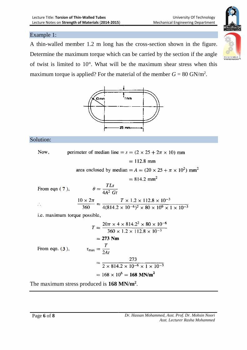
Example 1:
A thin-walled member 1.2 m long has the cross-section shown in the figure.
Determine the maximum torque which can be carried by the section if the angle
of twist is limited to 10°. What will be the maximum shear stress when this
maximum torque is applied? For the material of the member G = 80 GN/m2.
Solution:
The maximum stress produced is 168 MN/m2.
Lecture Title: Torsion of Thin-Walled Tubes Lecture Notes on Strength of Materials (2014-2015)
University Of Technology Mechanical Engineering Department
Page 7 of 8 Dr. Hassan Mohammed, Asst. Prof. Dr. Mohsin Noori
Asst. Lecturer Rasha Mohammed
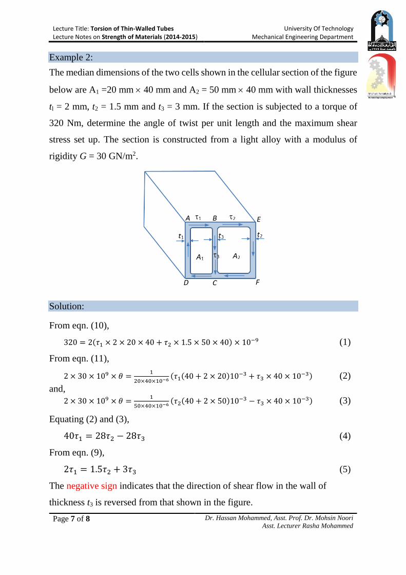
Example 2:
The median dimensions of the two cells shown in the cellular section of the figure
below are A1 =20 mm 40 mm and A2 = 50 mm 40 mm with wall thicknesses
tl = 2 mm, t2 = 1.5 mm and t3 = 3 mm. If the section is subjected to a torque of
320 Nm, determine the angle of twist per unit length and the maximum shear
stress set up. The section is constructed from a light alloy with a modulus of
rigidity G = 30 GN/m2.
Solution:
From eqn. (10),
320 = 2(𝜏1 × 2 × 20 × 40 + 𝜏2 × 1.5 × 50 × 40) × 10−9 (1)
From eqn. (11),
2 × 30 × 109 × 𝜃 =1
20×40×10−6(𝜏1(40 + 2 × 20)10−3 + 𝜏3 × 40 × 10−3) (2)
and,
2 × 30 × 109 × 𝜃 =1
50×40×10−6(𝜏2(40 + 2 × 50)10−3 − 𝜏3 × 40 × 10−3) (3)
Equating (2) and (3),
40𝜏1 = 28𝜏2 − 28𝜏3 (4)
From eqn. (9),
2𝜏1 = 1.5𝜏2 + 3𝜏3 (5)
The negative sign indicates that the direction of shear flow in the wall of
thickness t3 is reversed from that shown in the figure.
Lecture Title: Torsion of Thin-Walled Tubes Lecture Notes on Strength of Materials (2014-2015)
University Of Technology Mechanical Engineering Department
Page 8 of 8 Dr. Hassan Mohammed, Asst. Prof. Dr. Mohsin Noori
Asst. Lecturer Rasha Mohammed
Solving equations (1), (4) and (5) for 1, 2 and 3,
𝜏1 = 27.6 MPa, 𝜏2 = 38.6 MPa and 𝜏3 = −0.9 MPa
The maximum shear stress present in the section is thus 38.6 MN/m2 in the 1.5
mm wall thickness.
From eqn. (3),
2 × 30 × 109 × 𝜃 =1×10³
20×40×10−6(27.6 × (40 + 2 × 20) − 0.9 × 40)
∴ 𝜃 = 0.04525 𝑟𝑎𝑑. = 2.592° (Answer)
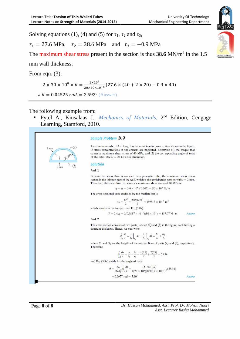
The following example from:
Pytel A., Kiusalaas J., Mechanics of Materials, 2nd Edition, Cengage
Learning, Stamford, 2010.
Lecture Title: Torsion of Circular Shafts Lecture Notes on Strength of Materials (2014-2015)
University Of Technology Mechanical Engineering Department
Page 1 of 14 Dr. Hassan Mohammed, Asst. Prof. Dr. Mohsin Noori
Asst. Lecturer Rasha Mohammed
TORSION OF CIRCULAR SHAFT
Introduction
In many engineering applications, members are required to carry torsional loads.
In this lecture, we consider the torsion of circular shafts. Because a circular cross
section is an efficient shape for resisting torsional loads, circular shafts are
commonly used to transmit power in rotating machinery. Derivation of the
equations used in the analysis follows these steps:
Make simplifying assumptions about the deformation based on
experimental evidence.
Determine the strains that are geometrically compatible with the assumed
deformations.
Use Hooke’s law to express the equations of compatibility in terms of
stresses.
Derive the equations of equilibrium. (These equations provide the
relationships between the stresses and the applied loads.)
Torsion of Circular Shafts
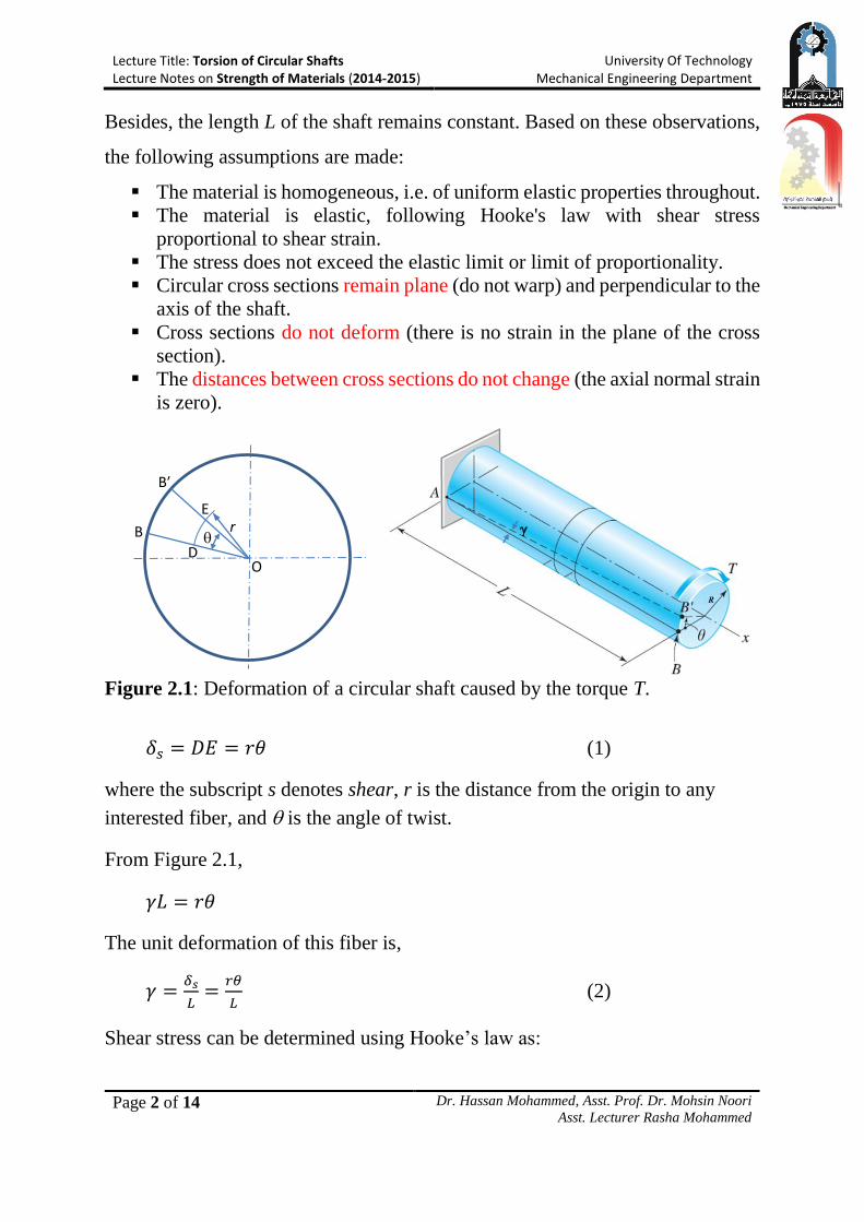
Consider the solid circular shaft, shown in the Figure 2.1, and subjected to a
torque T at the end of the shaft. The fiber AB on the outside surface, which is
originally straight, will be twisted into a helix AB′ as the shaft is twist through the
angle θ. During the deformation, the cross sections remain circular (NOT
distorted in any manner) - they remain plane, and the radius r does not change.
Lecture Title: Torsion of Circular Shafts Lecture Notes on Strength of Materials (2014-2015)
University Of Technology Mechanical Engineering Department
Page 2 of 14 Dr. Hassan Mohammed, Asst. Prof. Dr. Mohsin Noori
Asst. Lecturer Rasha Mohammed
Besides, the length L of the shaft remains constant. Based on these observations,
the following assumptions are made:
The material is homogeneous, i.e. of uniform elastic properties throughout.
The material is elastic, following Hooke's law with shear stress
proportional to shear strain.
The stress does not exceed the elastic limit or limit of proportionality.
Circular cross sections remain plane (do not warp) and perpendicular to the
axis of the shaft.
Cross sections do not deform (there is no strain in the plane of the cross
section).
The distances between cross sections do not change (the axial normal strain
is zero).
Figure 2.1: Deformation of a circular shaft caused by the torque T.
𝛿𝑠 = 𝐷𝐸 = 𝑟𝜃 (1)
where the subscript s denotes shear, r is the distance from the origin to any
interested fiber, and is the angle of twist.
From Figure 2.1,
𝛾𝐿 = 𝑟𝜃
The unit deformation of this fiber is,
𝛾 =𝛿𝑠
𝐿=
𝑟𝜃
𝐿 (2)
Shear stress can be determined using Hooke’s law as:
O
B
E
D
B′
r
Lecture Title: Torsion of Circular Shafts Lecture Notes on Strength of Materials (2014-2015)
University Of Technology Mechanical Engineering Department
Page 3 of 14 Dr. Hassan Mohammed, Asst. Prof. Dr. Mohsin Noori
Asst. Lecturer Rasha Mohammed
𝜏 = 𝐺𝛾 = 𝐺 (𝑟𝜃
𝐿) (3)
Note: since 𝜏 = (𝐺𝜃
𝐿) 𝑟 = 𝑐𝑜𝑛𝑠𝑡. 𝑟, therefore, the
conclusion is that the shearing stress at any
internal fiber varies linearly with the radial
distance from the axis of the shaft.
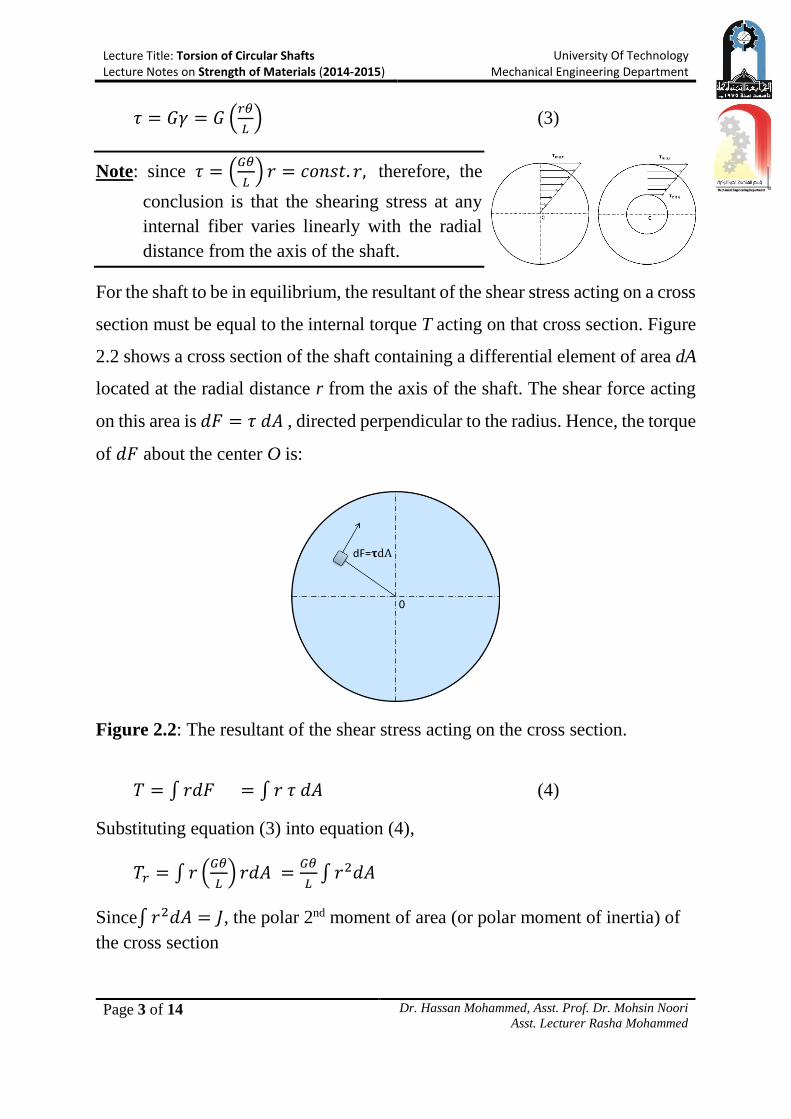
For the shaft to be in equilibrium, the resultant of the shear stress acting on a cross
section must be equal to the internal torque T acting on that cross section. Figure
2.2 shows a cross section of the shaft containing a differential element of area dA
located at the radial distance r from the axis of the shaft. The shear force acting
on this area is 𝑑𝐹 = 𝜏 𝑑𝐴 , directed perpendicular to the radius. Hence, the torque
of 𝑑𝐹 about the center O is:
Figure 2.2: The resultant of the shear stress acting on the cross section.
𝑇 = ∫ 𝑟𝑑𝐹 = ∫ 𝑟 𝜏 𝑑𝐴 (4)
Substituting equation (3) into equation (4),
𝑇𝑟 = ∫ 𝑟 (𝐺𝜃
𝐿) 𝑟𝑑𝐴 =
𝐺𝜃
𝐿∫ 𝑟2𝑑𝐴
Since∫ 𝑟2𝑑𝐴 = 𝐽, the polar 2nd moment of area (or polar moment of inertia) of
the cross section
Lecture Title: Torsion of Circular Shafts Lecture Notes on Strength of Materials (2014-2015)
University Of Technology Mechanical Engineering Department
Page 4 of 14 Dr. Hassan Mohammed, Asst. Prof. Dr. Mohsin Noori
Asst. Lecturer Rasha Mohammed
𝑇 =𝐺𝜃
𝐿𝐽
Rearranging the above equation,
𝜃 =𝑇𝐿
𝐽𝐺 (5)
where T is the applied torque (N.m), L is length of the shaft (m), G is the shear
modulus (N/𝑚2), J is the polar moment of inertia (𝑚4), and is the angle of twist
in radians.
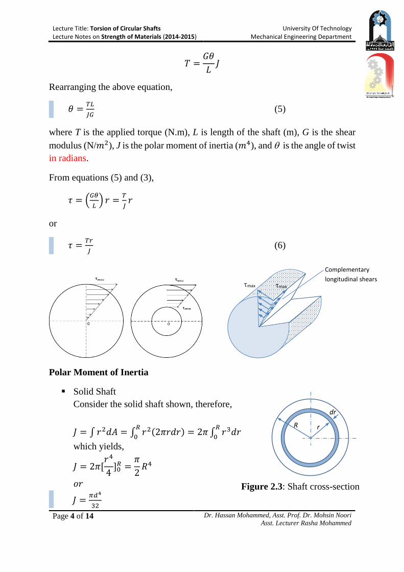
From equations (5) and (3),
𝜏 = (𝐺𝜃
𝐿) 𝑟 =
𝑇
𝐽𝑟
or
𝜏 =𝑇𝑟
𝐽 (6)
Polar Moment of Inertia
Solid Shaft
Consider the solid shaft shown, therefore,
𝐽 = ∫ 𝑟2𝑑𝐴 = ∫ 𝑟2(2𝜋𝑟𝑑𝑟)𝑅
0= 2𝜋 ∫ 𝑟3𝑑𝑟
𝑅
0
which yields,
𝐽 = 2𝜋[𝑟4
4]0
𝑅 =𝜋
2𝑅4
𝑜𝑟
𝐽 =𝜋𝑑4
32
max max
Complementary
longitudinal shears
R r
dr
Figure 2.3: Shaft cross-section
Lecture Title: Torsion of Circular Shafts Lecture Notes on Strength of Materials (2014-2015)
University Of Technology Mechanical Engineering Department
Page 5 of 14 Dr. Hassan Mohammed, Asst. Prof. Dr. Mohsin Noori
Asst. Lecturer Rasha Mohammed
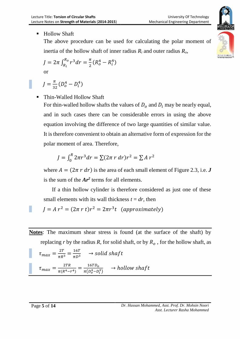
Hollow Shaft
The above procedure can be used for calculating the polar moment of
inertia of the hollow shaft of inner radius Ri and outer radius Ro,
𝐽 = 2𝜋 ∫ 𝑟3𝑑𝑟𝑅𝑜
𝑅𝑖=
𝜋
2(𝑅𝑜
4 − 𝑅𝑖4)
or
𝐽 =𝜋
32(𝐷𝑜
4 − 𝐷𝑖4)
Thin-Walled Hollow Shaft
For thin-walled hollow shafts the values of 𝐷𝑜 and 𝐷𝑖 may be nearly equal,
and in such cases there can be considerable errors in using the above
equation involving the difference of two large quantities of similar value.
It is therefore convenient to obtain an alternative form of expression for the
polar moment of area. Therefore,
𝐽 = ∫ 2𝜋𝑟3𝑑𝑟𝑅
0= ∑(2𝜋 𝑟 𝑑𝑟)𝑟2 = ∑ 𝐴 𝑟2
where 𝐴 = (2𝜋 𝑟 𝑑𝑟) is the area of each small element of Figure 2.3, i.e. J
is the sum of the Ar2 terms for all elements.
If a thin hollow cylinder is therefore considered as just one of these
small elements with its wall thickness t = dr, then
𝐽 = 𝐴 𝑟2 = (2𝜋 𝑟 𝑡)𝑟2 = 2𝜋𝑟3𝑡 (𝑎𝑝𝑝𝑟𝑜𝑥𝑖𝑚𝑎𝑡𝑒𝑙𝑦)
Notes: The maximum shear stress is found (at the surface of the shaft) by
replacing r by the radius R, for solid shaft, or by 𝑅𝑜 , for the hollow shaft, as
𝜏𝑚𝑎𝑥 =2𝑇
𝜋𝑅3=
16𝑇
𝜋𝐷3 → 𝑠𝑜𝑙𝑖𝑑 𝑠ℎ𝑎𝑓𝑡
𝜏𝑚𝑎𝑥 =2𝑇𝑅
𝜋(𝑅4−𝑟4)=
16𝑇𝐷𝑜
𝜋(𝐷𝑜4−𝐷𝑖
4) → ℎ𝑜𝑙𝑙𝑜𝑤 𝑠ℎ𝑎𝑓𝑡
Lecture Title: Torsion of Circular Shafts Lecture Notes on Strength of Materials (2014-2015)
University Of Technology Mechanical Engineering Department
Page 6 of 14 Dr. Hassan Mohammed, Asst. Prof. Dr. Mohsin Noori
Asst. Lecturer Rasha Mohammed
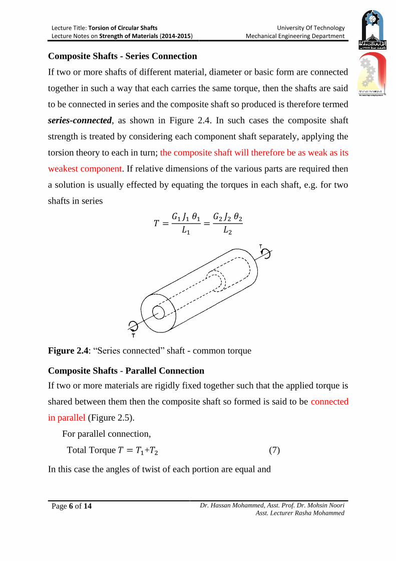
Composite Shafts - Series Connection
If two or more shafts of different material, diameter or basic form are connected
together in such a way that each carries the same torque, then the shafts are said
to be connected in series and the composite shaft so produced is therefore termed
series-connected, as shown in Figure 2.4. In such cases the composite shaft
strength is treated by considering each component shaft separately, applying the
torsion theory to each in turn; the composite shaft will therefore be as weak as its
weakest component. If relative dimensions of the various parts are required then
a solution is usually effected by equating the torques in each shaft, e.g. for two
shafts in series
𝑇 =𝐺1 𝐽1 𝜃1
𝐿1=
𝐺2 𝐽2 𝜃2
𝐿2
Figure 2.4: “Series connected” shaft - common torque
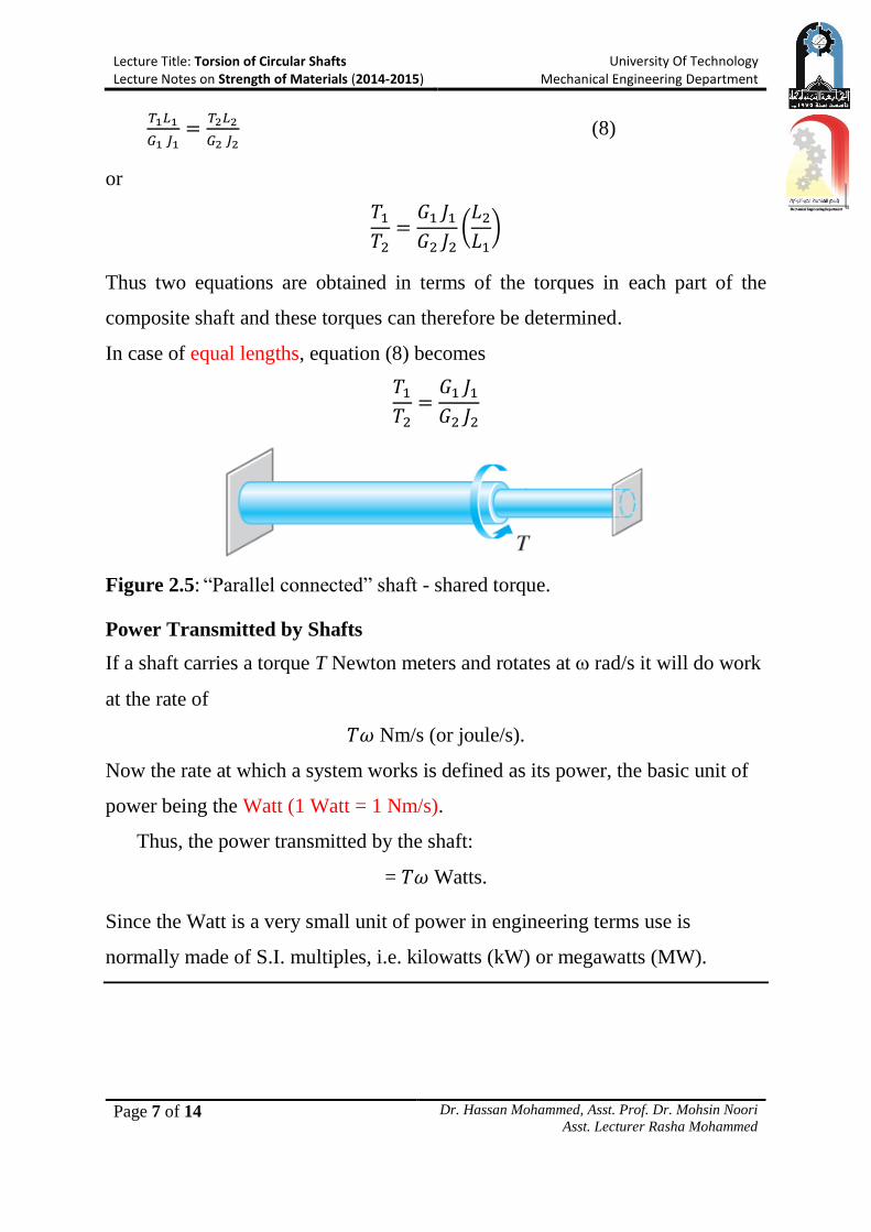
Composite Shafts - Parallel Connection
If two or more materials are rigidly fixed together such that the applied torque is
shared between them then the composite shaft so formed is said to be connected
in parallel (Figure 2.5).
For parallel connection,
Total Torque 𝑇 = 𝑇1+𝑇2 (7)
In this case the angles of twist of each portion are equal and
Lecture Title: Torsion of Circular Shafts Lecture Notes on Strength of Materials (2014-2015)
University Of Technology Mechanical Engineering Department
Page 7 of 14 Dr. Hassan Mohammed, Asst. Prof. Dr. Mohsin Noori
Asst. Lecturer Rasha Mohammed
𝑇1𝐿1
𝐺1 𝐽1=
𝑇2𝐿2
𝐺2 𝐽2 (8)
or
𝑇1
𝑇2=
𝐺1 𝐽1
𝐺2 𝐽2(
𝐿2
𝐿1)
Thus two equations are obtained in terms of the torques in each part of the
composite shaft and these torques can therefore be determined.
In case of equal lengths, equation (8) becomes
𝑇1
𝑇2=
𝐺1 𝐽1
𝐺2 𝐽2
Figure 2.5: “Parallel connected” shaft - shared torque.
Power Transmitted by Shafts
If a shaft carries a torque T Newton meters and rotates at rad/s it will do work
at the rate of
𝑇𝜔 Nm/s (or joule/s).
Now the rate at which a system works is defined as its power, the basic unit of
power being the Watt (1 Watt = 1 Nm/s).
Thus, the power transmitted by the shaft:
= 𝑇𝜔 Watts.
Since the Watt is a very small unit of power in engineering terms use is
normally made of S.I. multiples, i.e. kilowatts (kW) or megawatts (MW).
Lecture Title: Torsion of Circular Shafts Lecture Notes on Strength of Materials (2014-2015)
University Of Technology Mechanical Engineering Department
Page 8 of 14 Dr. Hassan Mohammed, Asst. Prof. Dr. Mohsin Noori
Asst. Lecturer Rasha Mohammed
Example1:
A solid shaft in a rolling mill transmits 20 kW at 120 r.p.m. Determine the
diameter of the shaft if the shearing stress is not to exceed 40MPa and the
angle of twist is limited to 6° in a length of 3m. Use G=83GPa.
Solution
Power = T ω
20103 = 𝑇1202𝜋
60
∴ 𝑇 =20103
4𝜋= 1590 𝑁. 𝑚
Since two design conditions have to be satisfied, i.e. strength (stress)
consideration, and rigidity (angle of twist) consideration. The calculations
will be as:
Based on strength consideration (𝜏𝑚𝑎𝑥 =16𝑇
𝜋𝐷3)
40106 =161590
𝜋𝐷3
∴ 𝐷 = 0.0587 = 58.7𝑚𝑚
Based on rigidity consideration (𝜃 =𝑇𝐿
𝐽𝐺)
𝜃 =𝑇𝐿
𝜋𝑑4
32 𝐺
6°𝜋
180=
3215903
𝜋𝑑483109
∴ D=0.0465 m= 46.5 mm
Therefore, the minimum diameter that satisfy both the strength and rigidity
considerations is D=58.7mm. (Answer)
Lecture Title: Torsion of Circular Shafts Lecture Notes on Strength of Materials (2014-2015)
University Of Technology Mechanical Engineering Department
Page 9 of 14 Dr. Hassan Mohammed, Asst. Prof. Dr. Mohsin Noori
Asst. Lecturer Rasha Mohammed
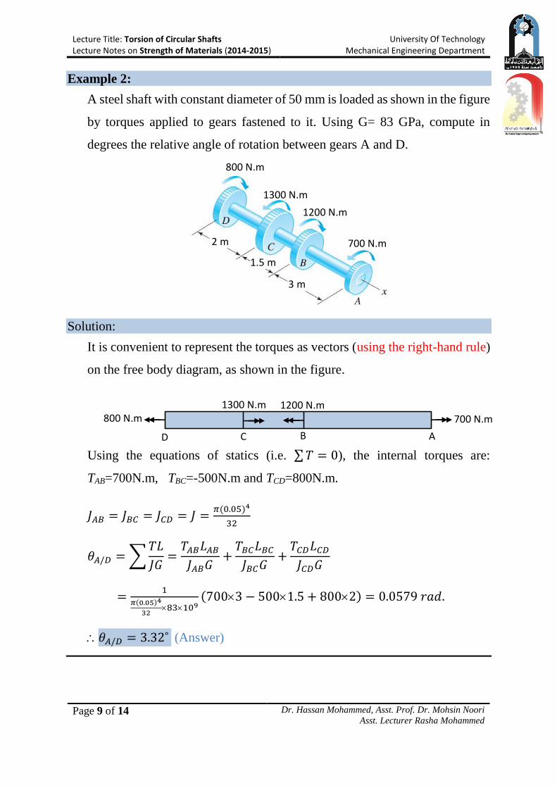
Example 2:
A steel shaft with constant diameter of 50 mm is loaded as shown in the figure
by torques applied to gears fastened to it. Using G= 83 GPa, compute in
degrees the relative angle of rotation between gears A and D.
Solution:
It is convenient to represent the torques as vectors (using the right-hand rule)
on the free body diagram, as shown in the figure.
Using the equations of statics (i.e. ∑ 𝑇 = 0), the internal torques are:
TAB=700N.m, TBC=-500N.m and TCD=800N.m.
𝐽𝐴𝐵 = 𝐽𝐵𝐶 = 𝐽𝐶𝐷 = 𝐽 =𝜋(0.05)4
32
𝜃𝐴/𝐷 = ∑𝑇𝐿
𝐽𝐺=
𝑇𝐴𝐵𝐿𝐴𝐵
𝐽𝐴𝐵𝐺+
𝑇𝐵𝐶𝐿𝐵𝐶
𝐽𝐵𝐶𝐺+
𝑇𝐶𝐷𝐿𝐶𝐷
𝐽𝐶𝐷𝐺
=1
𝜋(0.05)4
3283109
(7003 − 5001.5 + 8002) = 0.0579 𝑟𝑎𝑑.
𝜃𝐴/𝐷 = 3.32˚ (Answer)
700 N.m
1200 N.m
1300 N.m
800 N.m
3 m
1.5 m
2 m
800 N.m 1300 N.m 1200 N.m
700 N.m
D C B A
Lecture Title: Torsion of Circular Shafts Lecture Notes on Strength of Materials (2014-2015)
University Of Technology Mechanical Engineering Department
Page 10 of 14 Dr. Hassan Mohammed, Asst. Prof. Dr. Mohsin Noori
Asst. Lecturer Rasha Mohammed
T=1 kN.m
A
B
50 mm
1.5 m
B 75 mm
3 m
Steel Aluminum
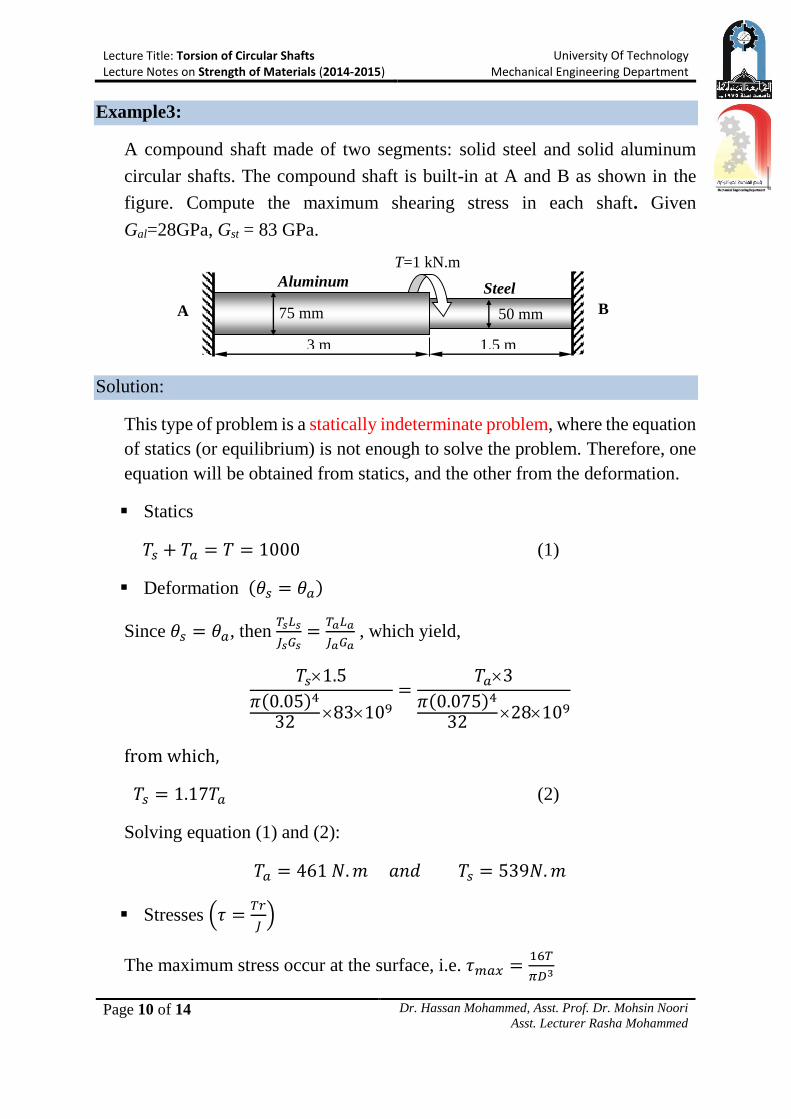
Example3:
A compound shaft made of two segments: solid steel and solid aluminum
circular shafts. The compound shaft is built-in at A and B as shown in the
figure. Compute the maximum shearing stress in each shaft. Given
Gal=28GPa, Gst = 83 GPa.
Solution:
This type of problem is a statically indeterminate problem, where the equation
of statics (or equilibrium) is not enough to solve the problem. Therefore, one
equation will be obtained from statics, and the other from the deformation.
Statics
𝑇𝑠 + 𝑇𝑎 = 𝑇 = 1000 (1)
Deformation (𝜃𝑠 = 𝜃𝑎)
Since 𝜃𝑠 = 𝜃𝑎, then 𝑇𝑠𝐿𝑠
𝐽𝑠𝐺𝑠=
𝑇𝑎𝐿𝑎
𝐽𝑎𝐺𝑎 , which yield,
𝑇𝑠1.5
𝜋(0.05)4
3283109
=𝑇𝑎3
𝜋(0.075)4
3228109
from which,
𝑇𝑠 = 1.17𝑇𝑎 (2)
Solving equation (1) and (2):
𝑇𝑎 = 461 𝑁. 𝑚 𝑎𝑛𝑑 𝑇𝑠 = 539𝑁. 𝑚
Stresses (𝜏 =𝑇𝑟
𝐽)
The maximum stress occur at the surface, i.e. 𝜏𝑚𝑎𝑥 =16𝑇
𝜋𝐷3
Lecture Title: Torsion of Circular Shafts Lecture Notes on Strength of Materials (2014-2015)
University Of Technology Mechanical Engineering Department
Page 11 of 14 Dr. Hassan Mohammed, Asst. Prof. Dr. Mohsin Noori
Asst. Lecturer Rasha Mohammed
T
A
B b
C
a
Steel Bronze
𝜏𝑎 =16∗461
𝜋(0.075)3= 5.57 MPa (Answer)
𝜏𝑠 =16∗539
𝜋(0.05)3= 22.0 MPa (Answer)
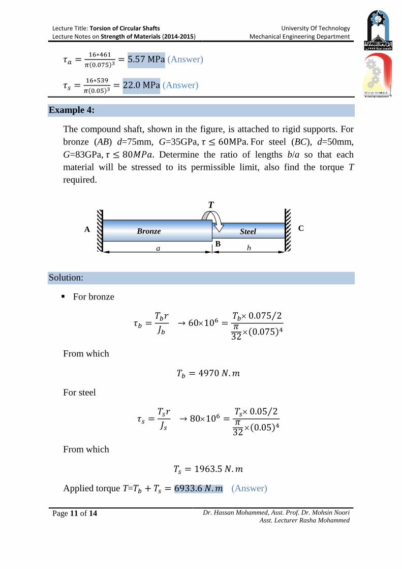
Example 4:
The compound shaft, shown in the figure, is attached to rigid supports. For
bronze (AB) d=75mm, G=35GPa, 𝜏 ≤ 60MPa. For steel (BC), d=50mm,
G=83GPa, 𝜏 ≤ 80𝑀𝑃𝑎. Determine the ratio of lengths b/a so that each
material will be stressed to its permissible limit, also find the torque T
required.
Solution:
For bronze
𝜏𝑏 =𝑇𝑏𝑟
𝐽𝑏 → 60106 =
𝑇𝑏0.075 2⁄𝜋
32(0.075)4
From which
𝑇𝑏 = 4970 𝑁. 𝑚
For steel
𝜏𝑠 =𝑇𝑠𝑟
𝐽𝑠 → 80106 =
𝑇𝑠0.05 2⁄𝜋
32(0.05)4
From which
𝑇𝑠 = 1963.5 𝑁. 𝑚
Applied torque T=𝑇𝑏 + 𝑇𝑠 = 6933.6 𝑁. 𝑚 (Answer)
B
Lecture Title: Torsion of Circular Shafts Lecture Notes on Strength of Materials (2014-2015)
University Of Technology Mechanical Engineering Department
Page 12 of 14 Dr. Hassan Mohammed, Asst. Prof. Dr. Mohsin Noori
Asst. Lecturer Rasha Mohammed
2T T
From the deformation 𝜃𝑠 = 𝜃𝑏,
𝑇𝑠𝐿𝑠
𝐽𝑠𝐺𝑠=
𝑇𝑏𝐿𝑏
𝐽𝑏𝐺𝑏→
1963.5𝑏𝜋
32(0.05)483109
=4970𝑎
𝜋
32(0.075)435109
From which
(b/a)=1.1856 (Answer)
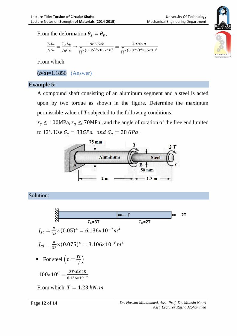
Example 5:
A compound shaft consisting of an aluminum segment and a steel is acted
upon by two torque as shown in the figure. Determine the maximum
permissible value of T subjected to the following conditions:
𝜏𝑠 ≤ 100MPa, 𝜏𝑎 ≤ 70MPa , and the angle of rotation of the free end limited
to 12°. Use 𝐺𝑠 = 83𝐺𝑃𝑎 𝑎𝑛𝑑 𝐺𝑎 = 28 𝐺𝑃𝑎.
Solution:
𝐽𝑠𝑡 =𝜋
32(0.05)4 = 6.13610−7𝑚4
𝐽𝑎𝑙 =𝜋
32(0.075)4 = 3.10610−6𝑚4
For steel (𝜏 =𝑇𝑟
𝐽)
100106 =2𝑇0.025
6.13610−7
From which, 𝑇 = 1.23 𝑘𝑁. 𝑚
Tal=3T Tst=2T
Lecture Title: Torsion of Circular Shafts Lecture Notes on Strength of Materials (2014-2015)
University Of Technology Mechanical Engineering Department
Page 13 of 14 Dr. Hassan Mohammed, Asst. Prof. Dr. Mohsin Noori
Asst. Lecturer Rasha Mohammed
For aluminum
70106 =3𝑇0.075 2⁄
3.10610−6
From which, 𝑇 = 1.93 𝑘𝑁𝑚
Deformation
𝜃 = ∑𝑇𝐿
𝐽𝐺=
𝑇𝑎𝐿𝑎
𝐽𝑎𝐺𝑎+
𝑇𝑠𝐿𝑠
𝐽𝑠𝐺𝑠
2𝑖=1
12𝜋
180=
3𝑇2
3.10610−628109+
2𝑇1.5
6.13610−783109
From which, T=1.64 kN.m
Therefore, the maximum safe value of torque (T) is T=1.23 kN.m (Answer)
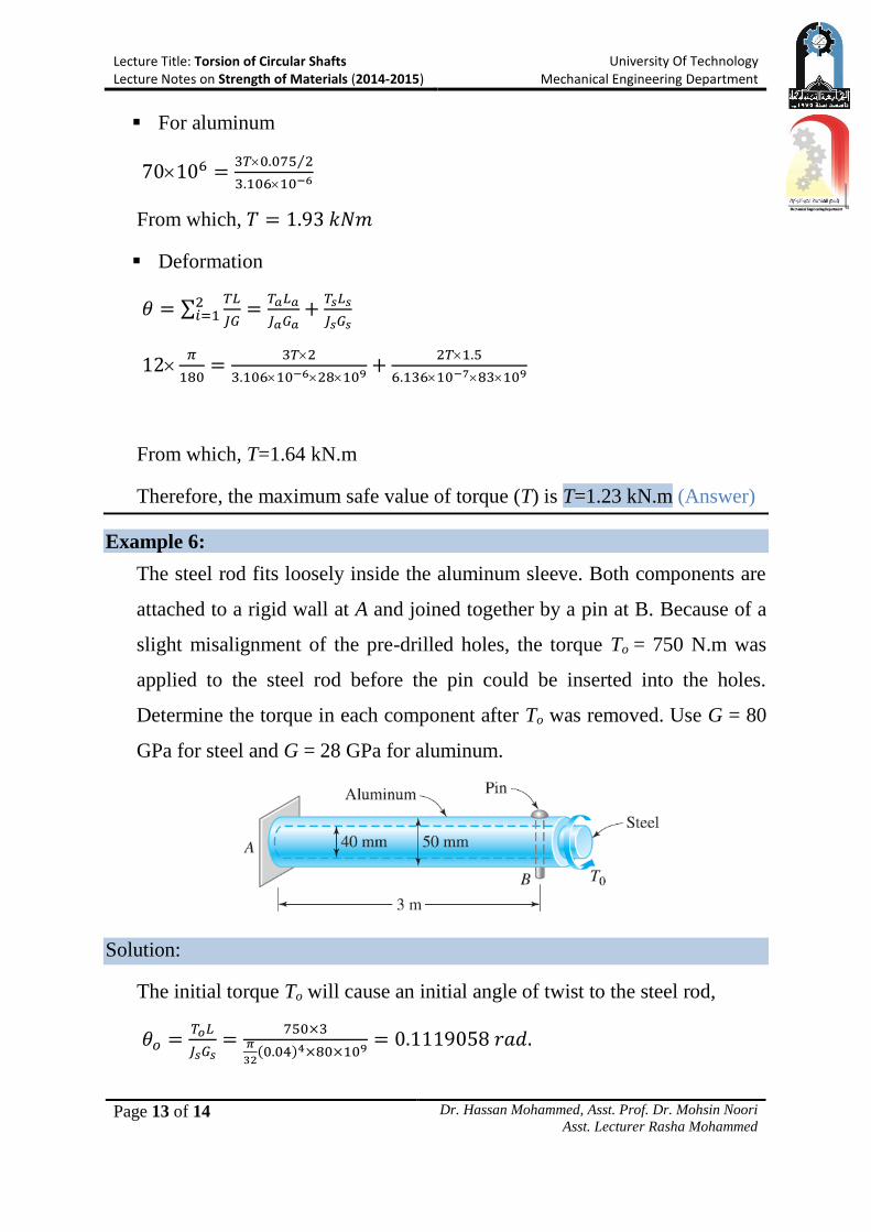
Example 6:
The steel rod fits loosely inside the aluminum sleeve. Both components are
attached to a rigid wall at A and joined together by a pin at B. Because of a
slight misalignment of the pre-drilled holes, the torque To = 750 N.m was
applied to the steel rod before the pin could be inserted into the holes.
Determine the torque in each component after To was removed. Use G = 80
GPa for steel and G = 28 GPa for aluminum.
Solution:
The initial torque To will cause an initial angle of twist to the steel rod,
𝜃𝑜 =𝑇𝑜𝐿
𝐽𝑠𝐺𝑠=
750×3𝜋
32(0.04)4×80×109
= 0.1119058 𝑟𝑎𝑑.
Lecture Title: Torsion of Circular Shafts Lecture Notes on Strength of Materials (2014-2015)
University Of Technology Mechanical Engineering Department
Page 14 of 14 Dr. Hassan Mohammed, Asst. Prof. Dr. Mohsin Noori
Asst. Lecturer Rasha Mohammed
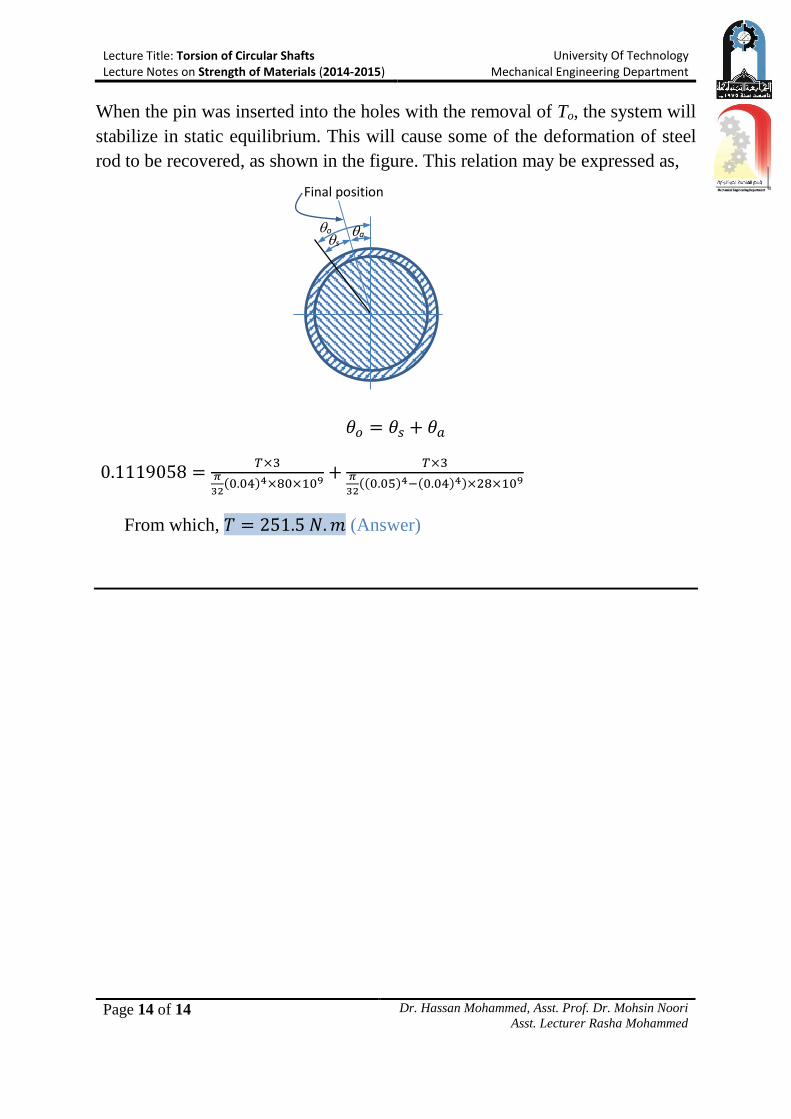
When the pin was inserted into the holes with the removal of To, the system will
stabilize in static equilibrium. This will cause some of the deformation of steel
rod to be recovered, as shown in the figure. This relation may be expressed as,
𝜃𝑜 = 𝜃𝑠 + 𝜃𝑎
0.1119058 =𝑇×3
𝜋
32(0.04)4×80×109
+𝑇×3
𝜋
32((0.05)4−(0.04)4)×28×109
From which, 𝑇 = 251.5 𝑁. 𝑚 (Answer)
Final position
a o s